Jason H. Steffen for the Holometer collaboration...
24
Jason H. Steffen for the Holometer collaboration (Fermilab E-990) Patras Workshop July 2012
Transcript of Jason H. Steffen for the Holometer collaboration...
Jason H. Steffen for the Holometer collaboration
(Fermilab E-990)
Patras Workshop
July 2012

Fermilab: Aaron Chou, Craig Hogan, Hank Glass, Gaston Gutierrez, Craig Hogan, Chris Stoughton, Ray Tomlin, James T. Volk, William Wester University of Chicago: Stephan Meyer, Ben Brubaker (now at Yale), Brittany Kamai, Bobby Lanza, Lee McCuller MIT: Rainier Weiss, Sam Waldman (now at SpaceX) University of Michigan: Dick Gustafson Northwestern: Jason Steffen (formerly Fermilab)
� �
�������������%������.�����) ��������
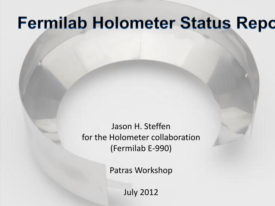
A single interferometer probes the spacetime that is enclosed within a cone-shaped spacetime volume.
With two, nested interferometers we can compare two simultaneous measurements of the same volume.
� �
�������������%������.�����) ��������
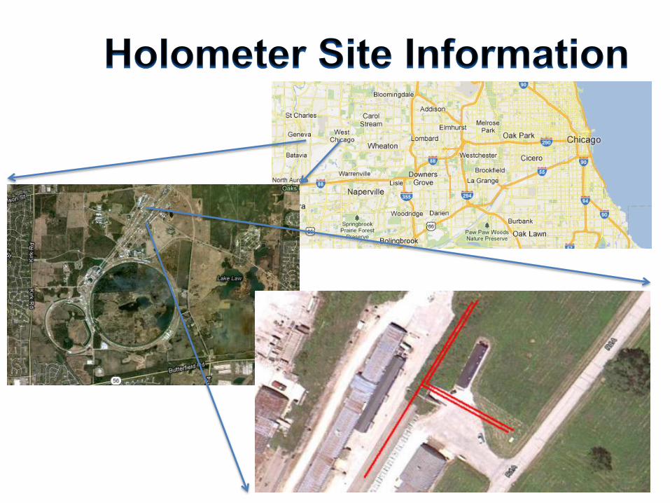
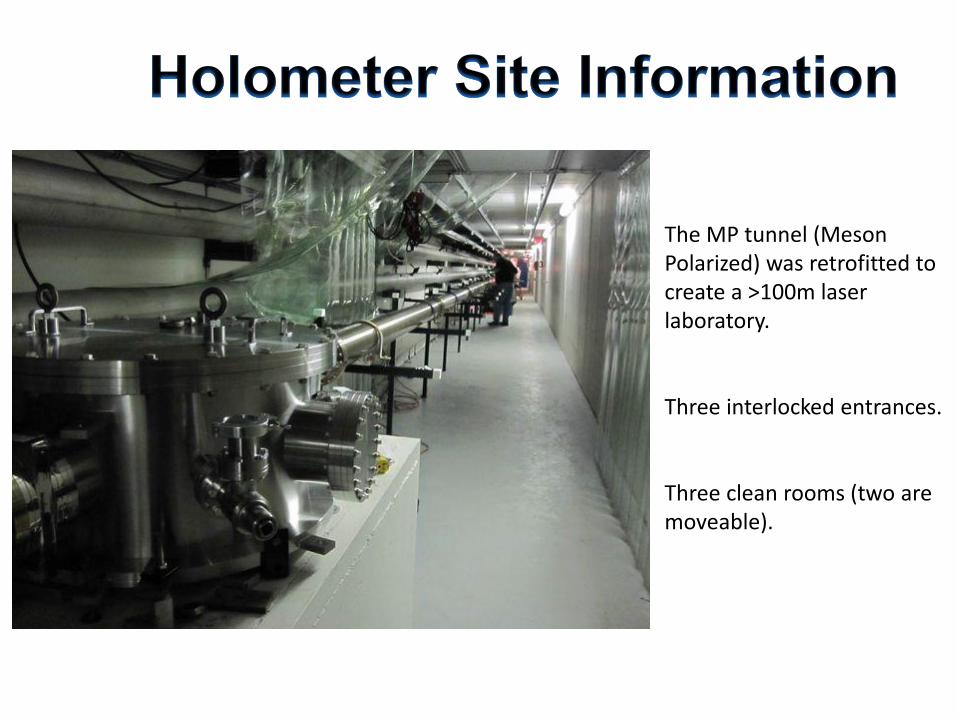
The MP tunnel (Meson Polarized) was retrofitted to create a >100m laser laboratory. Three interlocked entrances. Three clean rooms (two are moveable).

The east arms terminate in the newest Fermilab building. Interlocked with the tunnel lab. Climate controlled and lighted. Clean room. Concrete slab floor rests on 3 pillars driven ~2m deep.
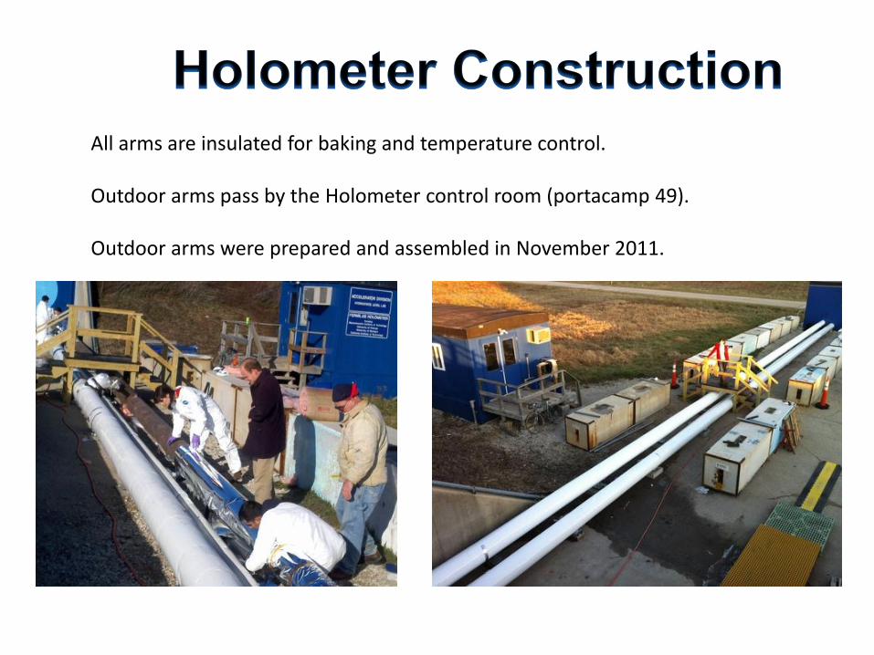
All arms are insulated for baking and temperature control. Outdoor arms pass by the Holometer control room (portacamp 49). Outdoor arms were prepared and assembled in November 2011.

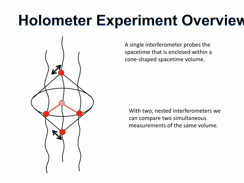
Corner stations located inside the tunnel, within a clean room. “T” interferometer is outside the “L” interferometer.
Two optical tables are near the corner stations. Electronics racks and work spaces are opposite the optical tables.
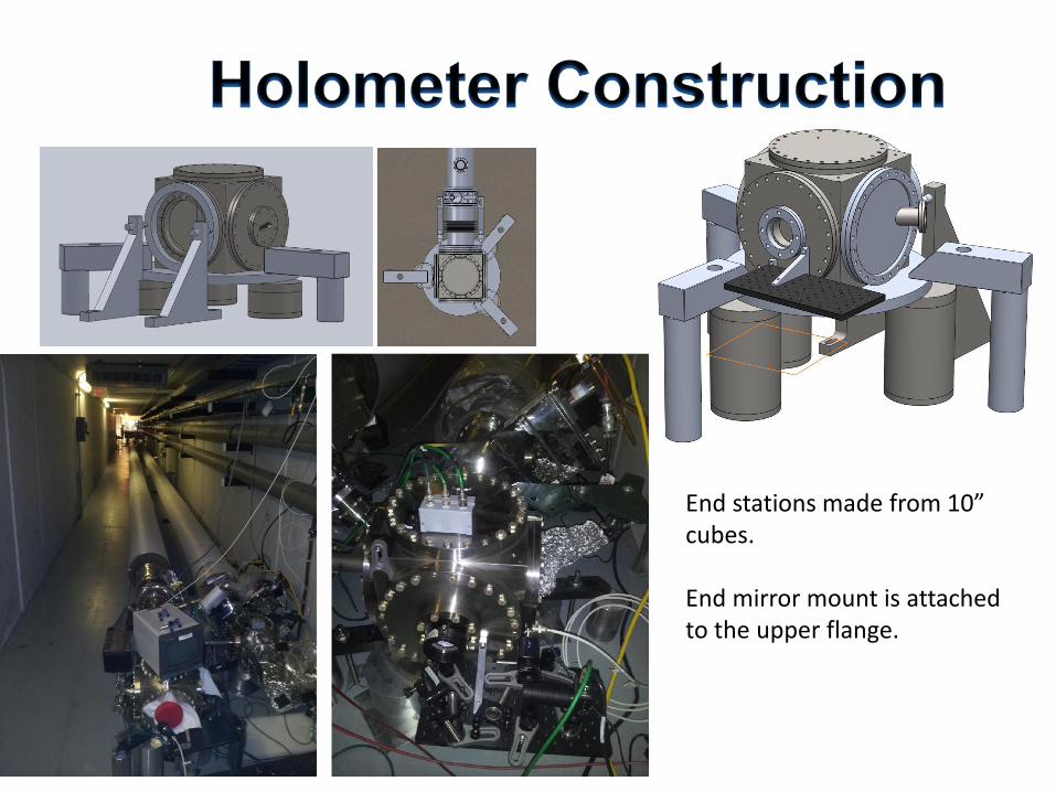
10 Inch Cube Endstation Design
S. Meyer
10 May 2011
1 Endstat ion
This is a study of the external support for a holometer endstation made of a Lesker 10"
cube. The cube has 6 10" conflat fi ttings, one on each side. The cube is supported by the
bottom flange which is dogged down to the concrete. The bottom flange also supports
the optics in the vacuum and provides the electrical feedthrough for the electronics
inside.
Figure 1: View of the endstation with clamp dogs and horizontal positioners. On the left is a view
showing the front of the cube without the bellows and 40m tube. On the right is a top view that
includes the bellows and 40 m tube going off to the top of the picture. The horizontal positioners
apply a horizontal force that balances the ∼ 400 lbs of the vacuum and permits adjustment along
the laser beam and provides horizontal steering of the beam.
One face has the connection to the 40 m tube through the bellows, the “front." The
back has a window for the transmitted light photodiode and camera. One side port
has a window for viewing the front side of the optic. The other two ports have conflat
blanks.
The bottom flange, which supports the optics, has a center made of a standard 10"
rotatable flange with two 15 pin D electrical connectors and blind holes for mounting
the optic. The outside ring is a modification of the standard conflat arrangement and
has the usual conflat bolt circle and clamping arrangement on the inside and an 18" OD.
The rotatable part can be setup with the optics stand and electrical wiring constructed
in the clean room with easy access while the cube is not mounted on the bottom flange.
When assembly is complete, the clamp ring and bottom flange are mounted onto the
10" cube. A reference mirror will be mounted to the outside of the 10" cube. The
1
Tuesday, May 17, 2011
End stations made from 10” cubes. End mirror mount is attached to the upper flange.

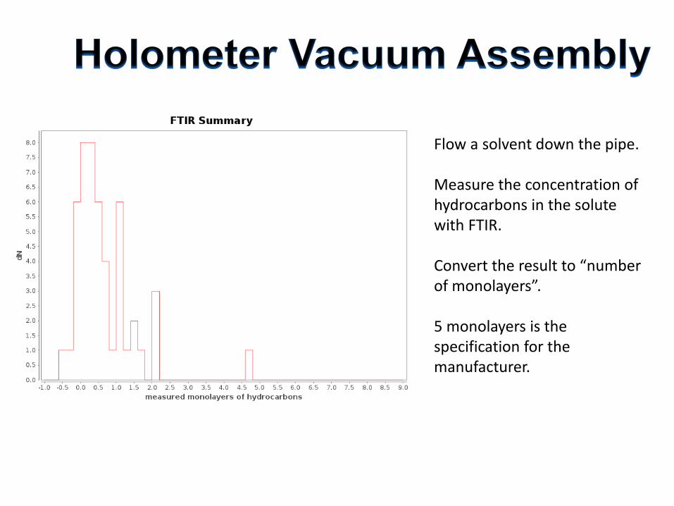
Hydrocarbons is the primary concern with the vacuum system. For prototype assembly we re-cleaned all of the arriving parts (trust but verify). Deemed too costly for the balance of the holometer. Now employ Fourier Transform Infrared Spectroscopy (FTIR) method used for LIGO.
2012/ 02/ 22
Figure5: Histogram of monolayersmeasured in tubes fabricated by Thermionicsand cleaned
by TMPI.
(including Acetone, which was used by the vendor for some cleaning operat ions) was reduced
to below 10− 12 torr.
page 8
Flow a solvent down the pipe. Measure the concentration of hydrocarbons in the solute with FTIR. Convert the result to “number of monolayers”. 5 monolayers is the specification for the manufacturer.

2012/ 02/ 22
Figure 7: RGA spectrum before and after bake
page 10
Bake each arm to > 150C independently by flowing current down the pipe itself. 300 A at 10-12 V, 3-7 days with turbopumps running. Combination of baking and FTIR specification yield acceptable hydrocarbon partial pressure (1e-12 Torr).

Continuous 2 W Mephisto Nd:YAG input laser. Mode cleaning ring cavity “pre mode cleaner”. Sidebands added for mode cleaning and for power recycling.
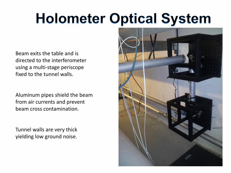
Beam exits the table and is directed to the interferometer using a multi-stage periscope fixed to the tunnel walls. Aluminum pipes shield the beam from air currents and prevent beam cross contamination. Tunnel walls are very thick yielding low ground noise.
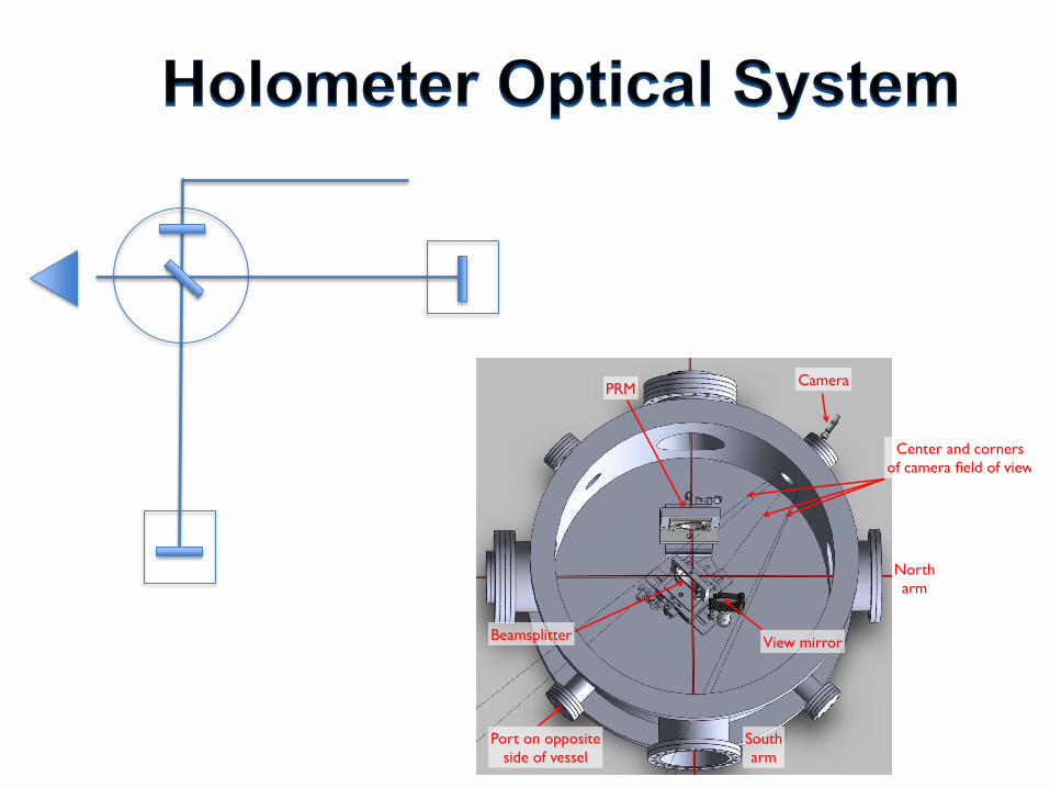
View mirror
PRM
Beamsplitter
Port on opposite
side of vessel
Camera
North
arm
South
arm
Center and corners
of camera field of view
Wednesday, October 5, 2011

Optical mounts in the interferometer are quite stable---no need for suspended optics.
Monday, December 12, 2011
! "# $%&' ( )$; 9<: => ?@$• AB$.12C"$DEF$+2' 6# &. , )G$-( .2+2C$1$)61H$I 1)"/ $&2$-6"$
/ +J "."2' "$I "-# ""2$/K21, +' $12/$)-1L ' $M.+' L&24$$> )")$*( N)")$# +-6$M1)-$.+)"=L , "$-&$."# +2/$-6"$DEF$M&NN&# "/$I K$
)N&# $M1NN=L , "$-&$-( .2$-6"$)61H4$$5&2-.&NN"/$I K$/ .+O".$( 2+-$# +-6$612/6"N/$-&CCN"$)# +-' 64$
• 5( . ."2-NK$*N12$-&$( )"$M&.$P"1, )*N+Q".G$DRS G$*&))+I NK$M&.$"2/ )-1L&2)4$
• D+' &, &-&.)$1."$N+, +-"/ $I K$, 1T+, ( , $U$NI $*( )6+2C$M&.' "4$
• > )"$&2$, &/+V"/$3+)W+K&( $DX=Y=@5$*+-' 68K1# $)-1C"$12/$, &/+V"/$Z[ S 47<<57=@5$7B$, +. .&.$, &( 2-G$# +-6$N&&)".$)*.+2C)4$$Z2$-6"$' 1)"$&M$DX=Y=@5G$-6"$O".L ' 1N$.")-&.+2C$M&.' "$+)$C.1O+-K4$
• \ : W$"1' 6$' 6122"N$
• @1' ( ( , =] ( 1N+V"/$M&.$( )"$+2$̂ 2612' "/ $_Z̀ a $
• F")-$( )+2C$b6&*"M( NNK$"] ( +O1N"2-c$2&2=O1' ( ( , $O".)+&2$# +-6$N"1/ )$' &22"' -"/ $-&$R` =U; $' &1T$' 1I N"4$$
! "# $%&' ( )$; 9<: => ?@$• AB$.12C"$DEF$+2' 6# &., )G$-( .2+2C$1$)61H$I 1)"/ $&2$-6"$
/ +J "."2' "$I "-# ""2$/K21, +' $12/$)-1L ' $M.+' L&24$$> )")$*( N)")$# +-6$M1)-$.+)"=L , "$-&$."# +2/ $-6"$DEF$M&NN&# "/$I K$
)N&# $M1NN=L , "$-&$-( .2$-6"$)61H4$$5&2-.&NN"/$I K$/ .+O".$( 2+-$# +-6$612/6"N/$-&CCN"$)# +-' 64$
• 5( . ."2-NK$*N12$-&$( )"$M&.$P"1, )*N+Q".G$DRS G$*&))+I NK$M&.$"2/ )-1L&2)4$
• D+' &, &-&.)$1."$N+, +-"/ $I K$, 1T+, ( , $U$NI $*( )6+2C$M&.' "4$
• > )"$&2$, &/+V"/$3+)W+K&( $DX=Y=@5$*+-' 68K1# $)-1C"$12/$, &/+V"/$Z[ S 47<<57=@5$7B$, +. .&.$, &( 2-G$# +-6$N&&)".$)*.+2C)4$$Z2$-6"$' 1)"$&M$DX=Y=@5G$-6"$O".L ' 1N$.")-&.+2C$M&.' "$+)$C.1O+-K4$
• \ : W$"1' 6$' 6122"N$
• @1' ( ( , =] ( 1N+V"/$M&.$( )"$+2$̂ 2612' "/ $_Z̀ a $
• F")-$( )+2C$b6&*"M( NNK$"] ( +O1N"2-c$2&2=O1' ( ( , $O".)+&2$# +-6$N"1/ )$' &22"' -"/ $-&$R` =U; $' &1T$' 1I N"4$$
Power recycling mirror and beamsplitter are steered by picomotors. Custom 3” beamsplitter mount.
End mirrors driven by piezo stacks. Custom mounts supported from above.
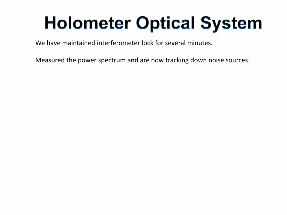
We have maintained interferometer lock for several minutes. Measured the power spectrum and are now tracking down noise sources.
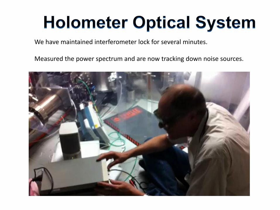
We have maintained interferometer lock for several minutes. Measured the power spectrum and are now tracking down noise sources.

EPICS: Experimental Physics and Industrial Control System MEDM: Motif EPICS Display Manager


Current: • The first interferometer is operating reliably, now exploring the
mechanical and electrical transfer functions and system noise sources. • Implementing a servo system with all computers far from the ADCs and
electronics. • We are installing the injection optics and interferometer optics in the
second system.
Remaining major milestones: • Finish assembly and commissioning of L interferometer. • Finish assembly and commissioning of T-south interferometer. • Begin science operations
1. We have a stable and very good, clean vacuum in both interferometers. We were able to bake the vacuum system in place. Optics surfaces will remain good.
2. We have optics, mirrors and beamsplitters, and optics actuators that are working as expected so far - we have not really pushed them but so far so good.
3. We have interferometer injection and transfer optics that work well launching from a table 5 meters from the beamsplitter
4. We have extremely stable optics mounting. Mount drifts are low - we did not know if non-suspended mounts would work at all before we started.
5. We have developed a flexible FPGA digital servo system that we expect will be able to run all the systems we need to lock.
6. We have been able to lock differential arm length loop and common arm length loop simultaneously for periods of minutes with the digital servo in the first of our interferometers.