January 2015 – v 2 - New Hampshire · 2016-06-22 · Contents NHDOT Bridge Design Manual v2.0...
108
January 2015 – v 2.0 (Revised March 2016)
Transcript of January 2015 – v 2 - New Hampshire · 2016-06-22 · Contents NHDOT Bridge Design Manual v2.0...
January 2015 – v 2.0
(Revised March 2016)

Page intentionally left blank.

Contents
NHDOT Bridge Design Manual v2.0 Page i
January 2015
Chapter 1 General Information 1.1 Manual Description 1.1-1 1.1.1 Purpose 1.1-1 1.1.2 Design Specifications 1.1-2 1.1.3 Design Methods 1.1-2 1.1.4 Revisions 1.1-2
1.2 Bridge Office Organization 1.2-1 1.2.1 Bridge Design Mission Statement 1.2-1 1.2.2 Organizational Elements and Design Responsibilities 1.2-1 1.2.3 Training/Mentor Program 1.2-4 1.2.4 Procedure for Project and Public Meetings 1.2-4 1.2.5 Contract Procedures 1.2-5
1.3 Quality Control/Quality Assurance (QC/QA) Procedure 1.3-1 1.3.1 General 1.3-1 1.3.2 In-House and Consultant Section Responsibilities 1.3-2 1.3.3 Project File 1.3-8 1.3.4 Contract Plans 1.3-9 1.3.5 Contract Plan Changes (Revisions After Proposal & As-Builts) 1.3-9 1.3.6 Addenda 1.3-10 1.3.7 Shop Plans and Permanent Structure Construction Procedures 1.3-11 1.3.8 Archiving Design Files & Permanent Structure Shop Plans 1.3-15 1.3.9 Public Disclosure Policy Regarding Bridge Plans & Files 1.3-18 1.3.10 Use of Computer Software 1.3-18
1.4 Project Development 1.4-1 1.4.1 General 1.4-1 1.4.2 Project Initiation and Authorization 1.4-1 1.4.3 Project Development Task List 1.4-1 1.4.4 Explanation of Project Development Task List 1.4-5
1.5 Bridge Design Scheduling 1.5-1 1.5.1 General 1.5-1 1.5.2 Preliminary Design Schedule 1.5-1 1.5.3 Final Design Schedule 1.5-1
References 1.R-1
Appendix A Appendix 1.1-A1 FHWA Memorandum 1.1-A1-1 Appendix 1.1-A2 Sample Design Memorandum 1.1-A2-1 Appendix 1.2-A1 Bridge Design Organization Chart 1.2-A1-1 Appendix 1.2-A2 Project Presentation Outline 1.2-A2-1 Appendix 1.3-A1 Project Turn-in QC/QA Worksheet 1.3-A1-1 Appendix 1.3-A2 Monthly Project Progress Report 1.3-A2-1 Appendix 1.3-A3 Plan File and Tub Location 1.3-A3-1 Appendix 1.3-A4 Incomplete Submittal for Documentation 1.3-A4-1 Appendix 1.3-A5 Bridge Design Software Applications 1.3-A5-1 Appendix 1.3-A6 Bridge Design Software Applications Cover Sheet 1.3-A6-1

Contents
NHDOT Bridge Design Manual v2.0 Page ii
January 2015
Appendix 1.3-A7 Examples of Contract Plan Revisions 1.3-A7-1 Appendix 1.4-A1 Project Development Schedule 1.4-A1-1 Appendix 1.4-A2 Procedure for Project Salvage Credits 1.4-A2-1 Appendix 1.4-A3 Guidelines for Use of 1000 Items 1.4-A3-1 Appendix 1.4-A4 Director Data Sheet Project Explanation Guidelines 1.4-A4-1 Appendix 1.5-A1 Person Hours Project Log 1.5-A1-1
Appendix C Appendix 1.1-C1 Record of Manual Revisions 1.1-C1-1

Chapter 1 General Information
NHDOT Bridge Design Manual v2.0 Page 1.1-1 January 2015
Chapter 1 General Information
1.1 Manual Description
1.1.1 Purpose
The Bridge Design Manual and Drawings have been prepared by the State of New Hampshire Department of Transportation, Bureau of Bridge Design.
Bridge Design Manual
The Bridge Design Manual (BDM) is a working document for use as a guide in the design of bridges, non-bridge structures, and in the preparation of contract plans. The BDM includes design guidelines, appendices, and quality control/quality assurance procedures intended to promote consistency and continuity of design work practices. The BDM does not constitute a specification or contract document.
The Bridge Design Manual promotes uniformity of practice and represents the current best thinking of the Bureau, yet at the same time permits the Engineer to exercise discretionary judgment in its implementation and provides for the incorporation of new ideas. Each Bureau member is encouraged to participate in keeping this document current as design practices change and improve. A departure from the guidelines shall be recorded and approved in writing in the permanent project records. The BDM shall be reviewed and revised periodically as necessary as noted in Section 1.1.4.
"Design guidelines" are herein defined as written procedures, instructions, practices, and "rules-of-thumb" used by the Bureau in the design of bridges and transportation related structures during the preparation of contract plans.
Appendices at the end of the chapters contain details, drawings, sketches, tables, charts, and notes, which reflect Bridge Design typical practice. Appendices are used in the design process, contribute to the preparation of plans, and may be incorporated directly or in part into contract plans.
The Bridge Design Manual is located on NHDOT’s website: http://www.nh.gov/dot/org/projectdevelopment/bridgedesign/manual.htm
Drawings: Bridge Detail Sheets, Details, and Sample Plans
Drawings are a compilation of detail sheets, details, and sample plans.
Bridge Detail Sheets are plan sheets prepared by the New Hampshire DOT for use on NHDOT projects. Others who use the Bridge Detail Sheets do so at their own risk. Bridge Detail Sheets are backed by engineering analysis, calculations, crash testing, and are approved by NHDOT Administrators and the Federal Highway Administration (FHWA). Only certain details can be modified by designers. As noted on each bridge sheet, if any modifications are made to details other than those noted, the engineer responsible for the modification becomes the Engineer of Record (EOR) for those details and for all effects the modifications may have on other components within the sheet. The sheets are located on NHDOT’s website: http://www.nh.gov/dot/org/projectdevelopment/bridgedesign/detailsheets/index.htm.
Bridge Details are considered nothing more than examples of items that are often used with very similar application from job to job. The details are intended to be copied to a project and modified to fit the particular aspects of the project. They are not intended to be included in a contract

Chapter 1 General Information
NHDOT Bridge Design Manual v2.0 Page 1.1-2 January 2015
plan set without close scrutiny for application to the job. The bridge details are located at: http://www.nh.gov/dot/org/projectdevelopment/bridgedesign/bridgedetails/index.htm
The Bureau of Bridge Design has assembled sample plans and bridge plan checklists that can be used as an aide in the preparation of construction plans for bridges. The sample plans and checklists are intended to be used only as a general guide, or reminder, to the designer, checker, and reviewer, and are not intended to be a replacement for the user’s own professional judgment based on sound engineering principles. It is the responsibility of the designer to provide the details that will allow the Contractor to construct the project as intended. The Bureau of Bridge Design makes these documents available on an "as is" basis. Details and items of the sample plans may have changed. It is the responsibility of the designer to provide the most current details and items on the contract plans. The sample plans are located at: http://www.nh.gov/dot/org/projectdevelopment/bridgedesign/sampleplans/index.htm
1.1.2 Design Specifications Bridges and transportation related structures shall be designed in accordance with the latest edition of the following specifications:
1. AASHTO LRFD Bridge Design Specifications 2. AASHTO Standard Specifications for Highway Bridges 3. NHDOT Standard Specifications for Road and Bridge Construction.
1.1.3 Design Methods
1. All new designs of superstructures and substructures shall be designed in accordance with the Load and Resistance Factor Design Method (LRFD) of the AASHTO Specifications, and rated in accordance with Load and Resistance Factor Rating (LRFR) of AASHTO Specifications, unless noted otherwise.
2. All rehabilitation designs of superstructure and substructure elements shall be designed in accordance with the Load and Resistance Factor Design Method (LRFD) of the AASHTO Specifications and rated in accordance with Load and Resistance Factor Rating (LRFR). This includes new bridge decks, and substructure elements for bridge widenings. Existing beams shall be analyzed for an HL-93 loading. If the existing beams do not have the capacity for an HL-93 loading, the Design Chief shall determine the design loading for the new beams. Any design method other than LRFD requires approval of the Design Chief. When widening an existing bridge, the designer should give consideration to matching the stiffness of the existing structure.
This policy went into effect October 1, 2007 per FHWA USDOT Memorandum dated January 22, 2007 (See Appendix 1.1-A1) and in accordance with New Hampshire Revised Statutes Annotated (RSA) 21-L:12-b, Bridge and Highway Construction Requirements for State Bridge Aid and State Highway Aid Projects.
1.1.4 Revisions
A. Manual Updates:

Chapter 1 General Information
NHDOT Bridge Design Manual v2.0 Page 1.1-3 January 2015
The Bridge Design Manual will change as new material is added and as criteria and specifications change, as follows:
1) Design Memorandums: Design changes to the Bridge Design Manual will be issued through Design Memorandums, by the Bureau of Bridge Design and will be posted on the NHDOT’s website: http://www.nh.gov/dot/org/projectdevelopment/bridgedesign/manual.htm .
Design memorandums state the design change, date, information and background on the design change. The Design Memorandums will remain in effect until superseded by a revision to the Bridge Manual. See Appendix 1.1-A2 for a sample Design Memorandum. Paper copies of the Design Memorandums can be placed with the Record of Revision Sheet (Appendix 1.1-C1).
2) Non-Design Revisions: Revisions to the Bridge Design Manual that do not involve any design change will be posted on the Bridge Design Manual Revision Document located on NHDOT’s website: http://www.nh.gov/dot/org/projectdevelopment/bridgedesign/manual.htm .
The revision history document will note the date, description, and location. No memorandum will be issued. These revisions will be made yearly by incorporating them into a new version of the Bridge Manual.
B. Record of Manual Updates:
New versions of the Bridge Design Manual will be issued yearly with a Publications Transmittal Form. The new version will incorporate all Active Design Memorandums and all Non-Design Revisions. The form will have a manual revision number and remarks regarding the revised sheets. The revision number shall be entered on the Record of Revision Sheet (Appendix 1.1-C1). Each manual holder shall keep a record of Design Memorandums or Bridge Manual Revisions on the Record of Revision sheet to verify that the manual is up to date.
C. Drawing Revisions:
Revisions made to the Bridge Detail Sheets, Bridge Details, and Sample Plans will be posted on the applicable drawing website. The date of the revision will be noted on the website page next to the drawing description. A revision history document located on each drawing website will note the revision date, description, location and background. No memorandum will be issued. Therefore, it is the designer’s responsibility to periodically check the website. The drawings are located at: http://www.nh.gov/dot/org/projectdevelopment/bridgedesign/documents.htm.

Chapter 1 General Information
NHDOT Bridge Design Manual v2.0 Page 1.1-4 January 2015
Page intentionally left blank.

Chapter 1 General Information
NHDOT Bridge Design Manual v2.0 Page 1.2-1 January 2015
1.2 Bridge Office Organization
1.2.1 Bridge Design Mission Statement
1) To design, draft, develop, and review plans and contract documents for bridge rehabilitation, replacement, maintenance, and/or new construction projects for state and municipal bridges by:
• Applying current design methods, details, and criteria. • Using both conventional and innovative construction materials and methods.
2) To develop economical, efficient, and durable bridges that are: • Environmentally and aesthetically sensitive to the context of each site and location. • Provide safe and dependable service to the traveling public. • Require minimal maintenance and preservation efforts. • Provide an anticipated service life of 75 years or greater.
3) To inspect, evaluate, and rate all state and municipal bridges to ensure the safe use of the state’s bridges by the traveling public.
1.2.2 Organizational Elements and Design Responsibilities
Bureau of Bridge Design consists of the following elements: (See Appendix 1.2-A1 for Organizational Chart):
1) Consultant Section
The Consultant Section is responsible for all projects that are contracted to Consultant Engineering firms for design.
• Prepares bridge Consultant agreements. • Negotiates bridge design contracts with Consultants. • Reviews Consultant plans. • Coordinates with the Consultant and other departments and agencies. • Prepares PS&E package for bid. • Gives presentations of the projects. • Develops design criteria, checks shop plans, and performs field inspections. • Assists Project Development Consultant Committee as required. • Provides construction services.
2) In-House Section:
The In-House Section is responsible for the structural engineering services within the NHDOT.
• Produces contract plans for bridges and structures, from initial design type, size and location (TS&L) to contract plans, within scope, schedule and budget. This involves designing, checking, reviewing, detailing, drafting, and developing specifications and cost estimates in an efficient and timely manner.

Chapter 1 General Information
NHDOT Bridge Design Manual v2.0 Page 1.2-2 January 2015
• Performs special design studies, develops design criteria, checks shop plans, and performs field inspections.
• Updates the Bridge Design Manual, NHDOT Standard Specifications, and Bridge Office Design Standards.
• Provides structural analysis and design for other departments. • Designs and drafts sign structure footings. • Provides preliminary cost estimates for municipal bridges. • Gives project presentations. • Writes articles of design projects for publications. • Provides construction services.
3) Existing Bridge Section:
The Existing Bridge Section directs activities and develops programs to assure the structural and functional integrity of all state bridges in service and directs emergency response activities when bridges are damaged.
The responsibilities of the Existing Bridge Section include the following: • Responsible for planning and implementing an inspection program for all the bridges
in the state. • Provides inspection services on state and town owned bridges.
All public highway bridges are inspected at least once every two years by Bridge Inspectors.
State bridges on the "Red List" are inspected twice every year. Town-owned Red List bridges are inspected once every year. All inventoried pedestrian bridges and railroad bridges are inspected under
these same guidelines. A "Red List" bridge is a bridge requiring interim inspections due to known
deficiencies, poor condition, weight restriction, or type of construction. All state-owned sign structures are inspected periodically by Bureau of Traffic.
Condition reports are prepared and kept on file for all inspected sign structures. • Inspections are conducted in accordance with the National Bridge Inspection
Standards (NBIS) and FHWA regulations. • Maintains the NH Bridge Inventory, a database containing current information on
state and town bridges in accordance with the NBIS. This includes load ratings for all bridges.
• Prepares a Bridge List of the state’s bridges, which is published every year, and prepares the annual Bridge Priority List, based on the latest inspection reports.
• Responsible for the bridge load rating and risk reduction (SCOUR) programs. (See Chapter 13, Bridge Rating and Chapter 3, Preliminary Design Requirements.)
• Provides damage assessments and emergency response services when bridges sustain damage due to vehicle collision, ship collision or natural phenomenon such as floods, wind, or earthquakes.

Chapter 1 General Information
NHDOT Bridge Design Manual v2.0 Page 1.2-3 January 2015
• Provides bridge condition data, which is used in prioritizing the repair or replacement of bridges.
• Reviews and approves Overload Permits for state bridges. • Prepares contract documents for bridge painting contracts. • Prepares contracts and coordinates activities for structural steel and painting
inspections. • Prepares contracts for bridge inspections, bridge ratings, and underwater inspections. • Develops and maintains manual for Scour Evaluation and Plan of Action of NH
Bridges, and Bridge Inspection manual.
4) Administrative Assistant:
The Administrative Assistant is responsible for the following: • Coordinates personnel actions. • Orders technical materials and office supplies and equipment. • Coordinates staff development and training. • Oversees and assigns work of clerical staff. • Processes contracts and agreements. • Schedules meetings. • Records staff timekeeping and payroll. • Completes typing, mailing, and filing responsibilities. • Manages inventories. • Requests and returns archived documents. • Handles customer requests for existing bridge plans or other documents.
5) Administrator:
The Administrator is responsible for overseeing all aspects of the bridge program, including: • Oversees development of bridge projects involving In-House or Consultant staff. • Represents the Department and Bureau at various technical and professional
meetings, such as Consultant Selection Committee, MSE Retaining Wall Committee, AASHTO Sub-Committee on Bridges and Structures, and others.
• Initiates and processes personnel actions for hiring, promotions, and discipline. • Prepares financial information on expenses and needs for Bridge Design Bureau
budget. • Oversees efforts for bridge inspection, rating, overweight permits, etc. • Testifies as needed at various hearings, including public, legislative, and
departmental. • Prepares and presents bridge-related information at various technical meetings,
conferences, and seminars. • Coordinates with Federal Highway Administration on bridge-related items for
compliance with federal regulations and requirements to ensure continued eligibility for federal programs.

Chapter 1 General Information
NHDOT Bridge Design Manual v2.0 Page 1.2-4 January 2015
• Responds to requests from the public, elected officials, state and federal agencies, and Department staff.
• Coordinates with other Bureaus and Districts to accomplish Department goals. • Additional administrative tasks and assignments, as needed, as directed.
1.2.3 Training/Mentor Program
The Bureau of Bridge Design has an established Trainee program for newly hired engineers and technicians that rotate through the Bureau of Bridge Design. The three (3) month program is developed for the new engineer to learn the processes required to bring a bridge project from TS&L to contract plans. The new engineer will follow the Trainee Manual located in the Bridge Design Library. The Trainee Manual guides the trainee and mentor through the following assignments:
• Site Visit • Bridge Geometry • Bridge Type • Hydraulic Study • Scope of Work • New Deck Design • Steel Beam Analysis • Abutment/Wingwall Design
The trainee will learn the design methods by hand calculations and check the hand calculations using computer programs. If the trainee has finished the assignments in the trainee manual, the Design Chief will assign project related work for their remaining time in Bridge Design.
Prior to the trainee leaving the Bureau, the mentor shall fill out the first part of the trainee evaluation form (S:\Bridge-Design\Forms\Trainee Evaluation Forms.doc) and the trainee fills out the second part of the form.
1.2.4 Procedure for Project and Public Meetings
The Project Engineer is responsible for setting up project meetings. If the meeting is located inside the NHDOT building and will include non-DOT employees, a Visitor Meeting List Form needs to be completed (S:\Bridge-Design\FORMS\PROJECT\Vistor Meeting Form.doc) and sent to the Front Reception Desk by email or a hard copy in person. This allows the Front Desk receptionist to direct visitors to the appropriate location.
The visitor policy states that the individual hosting visitors (i.e. all those who do not work in the JOMB) is responsible for those visitors with regard to emergency response actions. That is, the host shall explain the evacuation procedures to any/all visitors at the beginning of any meeting. Upon evacuation, those visitors would then proceed outside with their host and remain with the host at the host's Bureau assembly area. The meeting host is responsible for the headcount by ensuring that training/meeting attendance sheets are utilized for a quick and accurate count of any visitors once outside.
As noted in Chapter 1, Section 1.4, public meetings are part of the project development process. Each project will have either a Public Officials or a Public Informational Meeting. If

Chapter 1 General Information
NHDOT Bridge Design Manual v2.0 Page 1.2-5 January 2015
easements or land acquisitions are needed for the project to be built, a Public Hearing may be required. For more information regarding a Public Hearing, see Highway Design Manual, Chapter 10, Right-of-Way and refer to the following link: (http://www.nh.gov/dot/org/projectdevelopment/highwaydesign/designmanual/index.htm). A sample outline for a project presentation is shown on Appendix 1.2-A2 (S:\Bridge-Design\FORMS\PROJECT\Project Presentation Outline.doc).
1.2.5 Contract Procedures
Contract or Interstate Agreements are initiated by the Design Chief but the operational aspects are handled by the Administrative Assistant.
A. Consultant Agreements
Bureau of Bridge Design normally uses two types of Consultant contracts: 1) project specific and 2) statewide, to provide the following services:
• Bridge design and rating • Bridge painting consulting and inspection • Structural steel inspection • Underwater bridge inspection • Complex bridge inspection and rating
To secure the Consultant services for bridge design, complex bridge inspection, and bridge painting consulting and inspection, the procedures outlined in the manual “Consultant Selection and Service Agreement Procedures”, shall be followed.
To secure the Consultant services for structural steel and underwater diving inspection, the procedures outlined in the manual “Consultant Selection and Service Agreement Procedures for Prequalified Low Bid Technical Service Statewide Contracts, 2/26/1998”, shall be followed.
B. Interstate Agreements
The Department shall enter into an Interstate Agreement on projects involving New Hampshire and a neighboring state, whether Maine, Massachusetts, or Vermont. The Interstate Agreement must obtain Commissioner's Office approval and signature by officials of both states before obtaining approval by the NH Governor and Executive Council. Such an Agreement shall be obtained for the design and construction phases (one agreement to cover both phases) of a project before preliminary engineering money can be spent and before the project can be advertised for bids.
The Interstate Agreement establishes the percentage that each state will pay in the cost of the project. For bridges over water between NH and ME, the cost is split 50%-50%. The NH-VT state line runs along the Vermont shoreline established by the 1934 United State Supreme Court and Vermont New Hampshire Boundary Commission and the percentage for PE is based on its location. The percentage for construction is based on the actual amount of construction in each State. The project engineering is based on the existing bridge location, while the construction engineering is based on the proposed bridge location. For overhead costs of the project, the wording in the agreement shall state, “The indirect costs billed to VT shall be the current authorized rate from FHWA.” Agreements are located at S:\Bridge-Design\Admin\Agreement.

Chapter 1 General Information
NHDOT Bridge Design Manual v2.0 Page 1.2-6 January 2015
Page intentionally left blank.

Chapter 1 General Information
NHDOT Bridge Design Manual v2.0 Page 1.3-1 January 2015
Revised March 2016
1.3 Quality Control/Quality Assurance (QC/QA) Procedure
1.3.1 General
The purpose of the QC/QA procedure is to improve the quality of the structural designs and plans. The key element to the success of this process is effective communication between all parties. The goals of the QC/QA procedure are to:
1) Design structures that improve public safety and meet state regulations.2) Design structures that meet the requirements of the NHDOT Bridge Design Manual,
Bridge Detail Sheets, Bridge Details, Bridge Design Memorandums, AASHTO LRFDBridge Design Specifications, and current structural engineering practices.
3) Design structures that are aesthetically pleasing, constructable, durable, economical,inspectable, and require little maintenance.
4) Compile contract documents that meet the customer’s needs, schedule, budget, andconstruction requirements.
5) Minimize structural design costs.6) Produce an organized and indexed set of design calculations. Design criteria and
assumptions are included in the front after the index.7) Maximize plan quality.
The goals are listed in order of importance (high to low). If there is a conflict between goals, the more important goal takes precedence. The QC/QA procedure allows for change, innovation, and continuous improvement.
The Design Chief and the Senior Project Engineer determine project assignments and the QC/QA process to be used in preparation of the structural design. The intent of the QC/QA process is to facilitate plan production efficiency and cost-effectiveness while assuring the structural integrity of the design and maximizing the quality of the structural contract documents.
The Bridge Design QC/QA procedure is a project management process, which includes project reviews at specific milestones (TS&L, Preliminary Plans, PPS&E Plans, PS&E Plans and Contract Plans) along the Project Development timeline.
At the completion of each milestone (plan submission), the designer and checker shall perform a QC/QA review of the plans and sign-off on the QC/QA Worksheet (Appendix 1.3-A1, S:\Bridge-Design\Forms\Project\qcqa worksheet.doc). The QC/QA Worksheet shall be included with the plan submission to the Senior Project Engineer for a final review and sign-off. As noted on the QC/QA Worksheet, the QC/QA check of the plan submission shall include a review of the following:
Elevations and Dimensions Quantities and Rebar Lists Sheet Detailing Consistent with NHDOT Bridge Design Practices Contract Plan Detailing Consistent with NHDOT Bridge Design Practices Drafting Consistent with NHDOT Bridge Design Practices Item List Consistent with NHDOT Bridge Design Practices Notes Consistent with NHDOT Bridge Design Practices Incorporation of Comments by NHDOT Bureaus and Outside Agencies Load Rating

Chapter 1 General Information
NHDOT Bridge Design Manual v2.0 Page 1.3-2 January 2015
Revised March 2016
3-Way Check of Quantities (estimate quantities vs. plan vs. bid document)
1.3.2 In-House and Consultant Section Responsibilities
A. Design Team:
The design team usually consists of the Designer(s), Checker(s), Technician(s), Senior Project Engineer, and Project Manager who are responsible for preparing a set of contract documents on or before the scheduled due date(s) and within the budget allocated for the project.
The QC/QA procedures may vary depending on the type and complexity of the structure being designed, and the experience level of the design team members. More supervision, review, and checking may be required when the design team members are less experienced. In general, it is a good practice to have some experienced designers on every design team. All design team members shall have the opportunity to provide input to maximize the quality of the design plans.
B. In-House Design Section:
1) Designer Responsibility:
The designer is responsible for the content of the contract plan sheets, including structural analysis, completeness, and correctness. A good set of sample plans, which is representative of the bridge type and project scope, is indispensable as an aid to less experienced designers and detailers.
During the design phase of a project, the designer will need to communicate frequently with the Senior Project Engineer, Design Chief, and other Bureaus. The designer may have to organize face-to-face meetings to resolve constructability issues early in the design phase. If the Bureau of Highway Design is the lead Bureau for the project, the designer must coordinate the bridge plans with the highway plans.
The designer shall advise the Senior Project Engineer as soon as possible of any scope and cost increases and the reasons for the increases.
The designer is responsible for the following: a. Prepare design criteria that are included in the front of the design calculations. Compare
tasks with Bridge Design Manual (BDM) office practice and AASHTO bridge design specifications. • Sufficiency of design guidelines. • Justification for deviation from BDM/AASHTO. • Justification for design approach. • Justification for deviation from office practices regarding design and details. • Other differences.
b. Design and detail every aspect of the bridge, compute quantities and cost estimates. c. Develop the project from TS&L stage to contract bridge plans by applying engineering
principles and practices in accordance with NHDOT specifications; office practices and AASHTO design specifications.
d. Meet with the Senior Project Engineer and other Bureaus early in the design process to resolve as many issues as possible before proceeding with final design.
e. Identify coordination needs with other designers and Bureaus.
Chapter 1 General Information
NHDOT Bridge Design Manual v2.0 Page 1.3-3 January 2015
Revised March 2016
f. At least monthly or as directed by the design Senior Project Engineer, update the Monthly Project Progress Report Form (Appendix 1.3-A2, S:\Bridge-Design\Forms\Project\Monthly Progress Report.doc): • Estimate percent complete. • Estimate time to completion • Update project schedule
g. Develop quantities. h. Coordinate all final changes. i. Revise plans per checkers comments. j. Prepare the QC/QA Checklist, and obtain signatures/initials as required. This applies to
all projects regardless of type or importance (bridges, walls, sign structures, overlay, traffic barrier, etc.).
k. Load rate the bridge and complete the Form 4. l. Assist in resolving construction problems referred to the Bridge Design Office during the
life of the contract. These issues will generally be referred through the Bureau of Construction.
m. Check shop drawings to ensure conformity with plans, design, and office specifications.
The designer shall inform the Senior Project Engineer of any areas of the design which shall receive special attention during checking and review.
The design calculations are prepared by the designer and become a very important record document. Design calculations will be a reference document during the construction of the structure and throughout the life of the structure. It is critical that the design calculations be user friendly. The design calculations shall be well organized, clear, properly referenced, and include numbered pages along with a table of contents. Design and check calculations shall be bound and submitted to the Senior Project Engineer concurrently with the Bridge PS&E submittal. Calculations shall be stored in the Bureau of Bridge Design until completion of Final Audit. After the Final Audit, they shall be archived according to Section 1.3.8.
2) Checker Responsibility:
The checker is responsible for “quality control” of the structural design, which includes checking the design, plans, and specifications to assure accuracy and constructability. The Senior Project Engineer works with the checker to establish the level of checking required. The checking procedure for assuring the quality of the design will vary from project to project.
Some general checking guidelines are as follows: a. Design Calculations
• Design calculations shall be checked with independent calculations using independent software applications for the design. Iterative design methods may require a check by review of the designer’s calculations.
• All of the designer and checker calculations shall be placed in the project folder. • Revision of design calculations, if required, is the responsibility of the designer. • Check the load rating of the bridge and Form 4.
b. Plans • A complete check of the geometry using CADD or hand calculations.

Chapter 1 General Information
NHDOT Bridge Design Manual v2.0 Page 1.3-4 January 2015
Revised March 2016
• The checker’s plan review comments are recorded on a copy of the bridge plans, including details and rebar lists, and returned to the designer for consideration. These check prints are a vital part of the checking process, and shall be preserved. If the checker’s comments are not incorporated, the designer shall provide justification for not doing so. If there is a difference of opinion that cannot be resolved between the designer and checker, the Senior Project Engineer shall resolve any issues. Check prints shall be submitted to the Senior Project Engineer at the time of 100% PS&E turn-in.
• Revision of plans, if required, is the responsibility of the designer.
c. Quantities and Rebar List • The checker shall provide an independent set of quantity calculations. These
together with the designer’s quantity calculations shall be placed in the project folder.
• The checker shall also check the rebar list. • The checker shall cross-check items on plans with quantity list.
d. Quality Control/Quality Assurance • The checker shall perform a QC/QA review of the plans and sign-off on the
QC/QA Signature Sheet as noted in Section 1.3.1 and below: o Design improves public safety and meets state regulations. o Design meets the requirements of the NHDOT Bridge Design Manual,
Bridge Detail Sheets, Bridge Design Memorandums, AASHTO LRFD Bridge Design Specifications, and current structural engineering practices.
o Design is aesthetically pleasing, constructible, durable, economical, and inspectable.
o Contract documents meet the customer’s needs, schedule, budget, and construction requirements.
o Design costs are minimized. o An organized and indexed set of design calculations are produced. Design
criteria and assumptions are included in the front after the index. o Plan quality is maximized.
• If an independent design by the checker is different than that of the designer, but the designer’s design meets the design specifications and QC/QA criteria, then the designer has the final decision on the design and detailing. If the design does not meet all of the QC/QA criteria or specifications, then the Senior Project Engineer will decide on how to proceed with the design.
• If a new detail is shown on the bridge plans, the designer has the final decision on how to show the detail on the plans.
3) Technician Responsibility:
The technician/drafter is responsible for the quality and consistency of the contract plan sheets. The technician/drafter shall ensure that the Bridge Design drafting standards are upheld according to Chapter 11, Preparation of Plans.
The technician may be given rehabilitation projects to prepare for contract bids, such as bridge railing, deck, and/or expansion joint rehabilitation.

Chapter 1 General Information
NHDOT Bridge Design Manual v2.0 Page 1.3-5 January 2015
Revised March 2016
Some technician/drafter responsibilities are as follows: a. Detail plan sheets in a consistent manner and follow accepted detailing practices. b. Provide necessary and adequate information to ensure the contract plans are accurate,
complete, and readable. c. Check plans for geometry, reinforcing steel congestion, consistency, and accuracy of
control dimensions. d. Check for proper grammar and spelling. e. On multiple bridge contracts, work with the Designer/Senior Project Engineer to
ensure that the structural detailing of all bridges within the contract shall be coordinated to maximize consistency of detailing from bridge to bridge. Extra effort will be required to ensure uniformity of details, particularly if multiple design teams and/or Consultants are involved in preparing bridge plans.
4) Senior Project Engineer Responsibility:
The Senior Project engineer provides day-to-day leadership, project workforce planning, mentoring, and supervision for the design team. The Senior Project Engineer directs the project from TS&L phase to the PS&E package.
Some Senior Project Engineer responsibilities are as follows: a. Prepare the TS&L and scope of work. b. Perform the Project Development tasks needed from TS&L to the PS&E package
(Section 1.4.3 and 1.4.4). This includes coordinating meetings, giving presentations, and preparing permits, specifications, and cost estimates.
c. Coordinate scheduling of the design project. d. Solicit, receive, compile, and turn over to the designer all review comments received
from other Bureaus and outside agencies. It is imperative that all review comments are channeled through the Senior Project Engineer to ensure consistency between the final bridge plans, specifications, and estimate.
e. Work closely with the design team during the plan review phase and coordinate the needs of the design team. Review efforts shall concentrate on reviewing the completed plan details and design for completeness, and for agreement with office criteria and office practices. Review the following periodically and at the end of each submission: • Deviations from AASHTO and BDM, and proper consideration of any
applicable Design Memorandums • Design time and budget
f. Meet with the design team, Design Chief, and other Bureaus early in the design process to resolve as many issues as possible before proceeding with final design.
g. Identify coordination needs with other designers and Bureaus. h. Review the Monthly Project Progress Report Form updated by the designer
(Appendix 1.3-A2, S:\Bridge-Design\Forms\Project\Monthly Progress Report.doc), at least monthly or as directed by the Design Chief.
i. Resolve construction problems referred to the Bureau of Bridge Design during the life of the contract. These issues will generally be referred through the Bureau of Construction.
j. Provide preliminary cost estimates for municipal bridges.

Chapter 1 General Information
NHDOT Bridge Design Manual v2.0 Page 1.3-6 January 2015
Revised March 2016
k. Perform a final review and sign-off of the QC/QA Signature Sheet included with each plan submission as noted in Section 1.3.
5) Design Chief Responsibility:
The Design Chief reports to the Administrator, and is responsible for the timely completion and quality of the bridge plans.
The Design Chief works closely with the Senior Project Engineer and the design team (designer, checker, and technician) during the design and plan preparation phases to avoid major changes late in the design process.
Activities during the course of design include: a. Evaluate the complexity of the project and the designer’s skill to deliver the project
in a timely manner. Determine both the degree of supervision necessary for the designer and the amount of checking required by the checker.
b. Assist the design team in defining the scope of work, identifying the tasks to be accomplished, and developing a project work plan.
c. Make suitable staffing assignments and develop a design team time work hour estimate to ensure that the project can be completed within the schedule and budget.
d. Review and approve design criteria before the start of design. e. Assist the Senior Project Engineer conducting face-to-face project meetings with
other Bureaus and Consultants to resolve outstanding issues. f. Participate in coordinating, scheduling, and communicating with other Bureaus, the
public, and outside agencies relating to major structural design and construction issues.
g. Facilitate resolution of major project design issues. h. Assist the design team with planning, anticipating possible problems, collectively
identifying solutions, and facilitating timely delivery of needed information, such as geometrics, hydraulics, foundation information, etc.
i. Interact with the design team regularly to discuss progress, problems, schedule, budget, analysis techniques, constructability, and design issues. Always encourage forward thinking, innovative ideas, and suggestions for improving quality.
j. Arrange for and provide the necessary resources for the design team to do the job right the first time. Offer assistance to help resolve questions or problems.
k. Help document and disseminate information on special features and lessons learned for the benefit of others and future projects.
l. Mentor and train designers and technicians through the assignment of a variety of structure types.
m. Estimate time to complete the project. Plan resource allocation for completing the project to meet the scheduled Advetising Date and budget. Monitor monthly time spent on the project. • At the end of each month, estimate time remaining to complete project, percent
completed, and whether project is on or behind schedule. • Plan and assign workforce to ensure a timely delivery of the project within the
estimated time and budget. At monthly supervisors’ scheduling meetings, notify the Administrator and Project Manager if a project is behind schedule.

Chapter 1 General Information
NHDOT Bridge Design Manual v2.0 Page 1.3-7 January 2015
Revised March 2016
• Attend Project Development Project’s Review meetings held on last Wednesday of every month.
n. Advise the Administrator and Project Manager of any project scope change and construction cost increases.
o. Use appropriate computer scheduling software or other means to monitor time usage.
B. Consultant Section:
1) Design Chief Responsibility:
The Design Chief of the Consultant Section has similar responsibilities to the In-House Design Chief except the Consultant develops the bridge plans and estimates from TS&L stage to contract plans.
Additional responsibilities include: a. Review scope of work and fee proposal. b. Negotiate contract and Consultant’s task assignments. c. Coordinate/negotiate changes to scope of work and fee proposal. d. Prepare bridge Consultant agreements. e. Initiate a project start-up meeting with the Consultant to discuss design criteria,
submittal schedule and expectations, and also to familiarize himself/herself with the Consultant’s designers.
f. Coordinate with Consultant and other departments. g. Review municipal managed designs, estimates, specifications, scopes of work, and
fee proposals. h. Attend Project Development Project’s Review meetings held on last Wednesday of
every month.
2) Senior Project Engineer and Project Engineer Responsibility:
The Senior Project Engineer and Project Engineer of the Consultant Section have similar responsibilities to the In-House Senior Project Engineer except the Consultant develops the bridge plans and estimates from TS&L stage to contract plans. Upon completion of a project, the Senior Project Engineer or the Project Engineer shall evaluate the work of the Consulting Engineers with a “Past Performance Report”. The evaluation report is located at S:\Bridge-Design\Forms\Project\consult eval.doc. This report is processed through the Bureau Administrator to the Commissioner’s Office and then on to the Consultant Firm. The report is confidential and the original is kept on file in the Consultant master file in Highway Design. No other copies are to be made of this report.
Additional responsibilities include: a. Review Consultant plans for completeness and consistency with NHDOT practices.
The plans shall be checked for constructability, consistency, clarity, and compliance. b. Coordinate with Consultant and other Bureaus and departments. c. Prepare PS&E package for bid. d. Give presentations of the projects. e. Develop design criteria, check shop plans, and perform field inspections. f. Identify and assign responsibilities for what and when the review of all bridge plan
and construction submittals is to be completed.

Chapter 1 General Information
NHDOT Bridge Design Manual v2.0 Page 1.3-8 January 2015
Revised March 2016
g. Monitor progress of project. h. Facilitate communication, including face-to-face meetings. i. Provide construction services.
1.3.3 Project File
The Bridge Design Office maintains a project file of all pertinent design/check calculations and correspondence for documentation and future reference. Once the project is designed and advertised, the designer shall turn in the design and check calculations, and any relevant correspondence, to the Senior Project Engineer.
The front cover of the project folder shall have a label stating the following: Project Name Project Number Location Bridge Number Advertising Date Completion Date Designer, Checker, and Senior Project Engineer Names Pigeon Hole Numbers Plan File Number
The design/check calculation file shall include the following: Index of information included in folder Design criteria, calculations, quantity calculations, special design features, and
assumptions. Pertinent computer input and output data. Load rating calculations and copy of Form 4. Calculations for revisions made during construction shall be included in the file when
construction is completed. Two (2) extra copies of the quantity calculations to be given to the Construction Bureau
upon award of the project. CD that includes a copy of the contract plans (.dgn format) for the Contractor to use upon
award of the project. Geotechnical Report Hydraulic/Scour Report
The design/check calculations file exclusions: Irrelevant computer information Irrelevant sketches Voided sheets TS&L and Preliminary design calculations and drawings unless used in the final design
Chapter 1 General Information
NHDOT Bridge Design Manual v2.0 Page 1.3-9 January 2015
Revised March 2016
The project file shall be placed in the Active File Cabinet for the In-House section and the Consultant File Cabinet for the Consultant Section, until the project is archived (see Section 1.3.8). The Senior Project Engineer shall include any pertinent correspondence to the project file, along with any construction submittals received during construction of the project.
1.3.4 Contract Plans
The Contract Plans shall be developed according to Chapter 11, Preparation of Plans. Once the PS&E stage is complete, the contract plans shall be brought to the Print Shop for printing prior to advertising. If the Bureau of Highway Design is the lead Bureau for the project, then the Senior Project Engineer shall coordinate with Highway Design for when the bridge plans need to be given to Highway Design to include with their plans. The lead Bureau is responsible for bringing the plans to the Print Shop and distributing the printed sets (Section 1.4.4, Contract Plans, for print shop request form and distribution form). The contract plans shall be brought to the print shop a minimum of two (2) weeks prior to the advertising date, if the project is FHWA exempt. If the project requires FHWA review, the plans need to be brought to the print shop a minimum of six (6) weeks prior to the advertising date (this allows 2 weeks for printing and the sending PS&E package to FHWA for review 4 weeks prior to the advertising date (see Appendix 1.4-A1 for timeline of project development).
After the contract plans have been printed, they are stored in file tubs located in the Bureau of Bridge Design (See Appendix 1.3-A3 for tub and file locations, and Section 1.4.4, Preliminary Plans 40-50% for assigning a plan file number.). If Highway Design is the lead Bureau for the project, then the Senior Project Engineer needs to request the bridge plans from Highway Design, once they have been printed, and place them in the Bridge Design file tubs. If the project is a bridge replacement, the old bridge plans shall be pulled out of file tubs and given to the Chief of Existing Bridge Section for archiving. Any Preliminary Plans stored in the tub can be discarded once the bridge has been constructed and upon audit close-out of the project.
If the project is a bridge rehabilitation that was advertised through a proposal (no plans), the designer/drafter shall enter CAD/D and place the proposal bridge sheets into a full-size bridge border sheet. The file number to be placed in the bridge title box is the same file number as the rehabilitated bridge. Print out the bridge sheets and place them in the Bridge Design file tubs with the existing plans.
See Section 1.3.8, C, for information on filing contract plans electronically.
1.3.5 Contract Plan Changes (Revisions After Proposal & As-Builts)
Changes to the contract plans or proposal subsequent to advertising (i.e., contract plans printed) the project may require a contract plan revision. See Appendix 1.3-A7 for examples. When a revision or an additional plan sheet is necessary, the following shall be performed:
1) Changes to the contract paper/mylar plans stored in the file tubs shall be made with a pen by crossing out what is changing and adding to the sheet the revised portion.
2) No erasures are permitted. 3) Every revision will be assigned a number, which shall be enclosed inside a triangle. The
assigned number shall be placed both at the location of the change on the sheet and in the revision title block on the bottom of the plan sheet along with an explanation of the change.

Chapter 1 General Information
NHDOT Bridge Design Manual v2.0 Page 1.3-10 January 2015
Revised March 2016
4) Changes to the electronic copy of the contract plans shall be made by drawing lines over the graphics (crossing out the graphics), which require revision and note the revision with a triangle revision number, along with the revision title block and an explanation of the change. No graphics are to be deleted.
5) If a new or completely revised plan sheet is required as part of the revision, the information in the plan sheet title blocks must be identical to the contract plan title block. The new sheet shall be assigned the same number as the one in the original contract plan that it most closely resembles and shall be given a letter after the number (e.g., if the new sheet applies to the original sheet 25 of 53, then it will have a number 25A of 53).
6) If the project has Federal oversight, the revised plan sheet shall be sent to FHWA for review prior to forwarding copies to Construction Bureau and the Specifications Office.
7) Ask the District Construction Engineer and other plan recipients if they would like paper copies of the revised plan sheets (typically 6 full-size and 6 half-size) or electronic copies for distribution.
8) If the contract plans were developed by a Consultant, one (1) full-size and one (1) half-size copy of the revised sheet shall be transmitted to them.
The Bureau of Construction, Audit Section, records any field changes on As-Built plans (if needed). The “As-Built” plans are a plan set received from the Contract Administrator and stamped “As-Built” after the audit is complete. The As-Built plans are scanned and placed on the NHDOT intranet located at: http://dotweb/engineering/index.asp.
• If the project is a bridge-only project without any highway involvement, the Audit Section will give the As-Built plan to the Senior Project Engineer. The Senior Project Engineer shall review the As-Built plans.
• If there are significant changes and the plan set is in good condition, the contract plan stored in the tub should be replaced with the As-Built plan set. If the As-Built plan is in bad condition, any significant changes shall be transferred to the contract plan set and the front sheet noted “As-Built”.
• If there are no significant changes to the plan, the As-Built set can be recycled since a scanned copy is available. Only one set of plans (As-Built or Contract) shall be stored in the tub.
• If the project has highway involvement, the As-Built plan is given to Records Section to be archived. Bridge Design will not receive a paper copy.
1.3.6 Addenda
If errors or omissions are found with the contract plans or proposal, revisions maybe necessary. Also, questions from bidders may arise during the bid period that requires clarification. For that reason, it may be necessary to issue an addendum. The addendum form (S:\Bridge-Design\FORMS\PROJECT\AddendumTemplate.doc) shall be completed by the Senior Project Engineer to note the change/revision or clarification, reviewed by the Design Chief, signed by the Director of Project Development, and given to the Bureau of Finance and Contracts no later than three (3) days prior to the advertising date. For Federal oversight projects, a copy of the addendum needs to be sent to FHWA for approval after receiving the Project Director’s signature.
If the addendum changes item numbers, adds or deletes items, or revises quantities, it will require the Bid Schedule and Information Report to be revised and included as part of the addendum for those who obtained bid documents. The PS&E Estimate must also be revised to reflect these
Chapter 1 General Information
NHDOT Bridge Design Manual v2.0 Page 1.3-11 January 2015
Revised March 2016
changes for the bid opening and the Project Agreement estimate that will be generated as a result of the bids.
An example of an addendum can be found in the Highway Design Manual: http://www.nh.gov/dot/org/projectdevelopment/highwaydesign/designmanual/documents/CH13-Appendix11.pdf and S:\Bridge-Design\FORMS\PROJECT\Addendum Samples.
If there is a change to the contract plans, then the change/revision shall be described by wording in the addendum. The plans shall be marked with the change as noted in Section 1.3.5, Contract Plan Changes (Revision After Proposal & As-Builts). The potential bidders do not need a revised contract plan.
1.3.7 Shop Plans and Permanent Structure Construction Procedures
Shop plans shall be reviewed for conformance with the provisions of Section 105 of the NHDOT Standard Specifications for Road and Bridge Construction and general conformity with the contract plans and proposal.
Shop plans for fabrication of permanent structures/elements, or any other working drawings as noted in the contract proposal, shall be submitted to the Engineer for approval in accordance with Section 105. The Engineer will be allowed up to fifteen (15) working days for review of each submission. This fifteen (15) day period is defined from when the Contractor first submits the drawings to the Bureau of Construction and ends when the final “approved” submission is returned to the Contractor through the Bureau of Construction.
Shop plans showing temporary construction procedures/elements of the project, or any other working drawings as noted in the contract proposal, shall be submitted to the Engineer for documentation in accordance with Section 105. See Section 105 for a list of working drawings to be submitted for documentation.
If the shop plans are submitted electronically, the designer/checker may review and comment on the electronic version, or print out the shop plan and comment on the paper copy. If revisions are required, transmitting the electronic version takes less time to process. Once Construction receives the final “Approved” shop plan, the District Construction Engineer can request final paper copies per provisions of Section 105. See paragraph A.10 below for reviewing and transmitting electronic shop plans.
A. The following is a guide for checking shop plans of permanent structures/elements:
1) Items shall be checked for general conformity with the contract plans, proposal, addenda, special provisions, and standard specifications.
Material specifications Size of members and fasteners Dimensions shown on contract plans Finish (surface finish, galvanizing, anodizing, painting, etc.) Weld size, type, and procedures Strand or rebar placement (if changes are made, a new Load Rating may be required) Adequacy of details Fabrication (reaming, drilling, and assembly procedures) Layout
Chapter 1 General Information
NHDOT Bridge Design Manual v2.0 Page 1.3-12 January 2015
Revised March 2016
2) All submittals shall be transmitted through the Bureau of Construction. The checker of the shop plans shall make sure the District Construction Engineer is kept in communication (cc’d) with all transactions of the shop plans.
3) When submitting shop drawings for review, the transmittal letter shall include a description of the product and the name of the Fabricator, instead of just indicating “shop drawing” in the description box.
4) A copy of the structural steel, bridge railing, steel expansion joints, sign structures, or any other steel fabrication shop plans shall be given to the Steel Fabrication Engineer, Bureau of Bridge Design, for concurrent review.
5) A copy of geotechnical submittals, which may include special design proprietary retaining walls, drilled shafts, ground anchors, steel and soldier piles, shall be given to the Geotechnical Engineer, Bureau of Materials and Research, for concurrent review.
6) The Bridge Office copy shall show all comments/corrections with red pen and the checked items shall be highlighted with a yellow pencil. All comments/corrections shall be transferred onto the remaining copies with a red pen and shall be clear and neat. Comments shall be “bubbled” so they stand out. If the submittal is stamped “Approved Except as Noted. Resubmission Required” or “Disapproved”, then only two (2) copies need to be marked up and sent back to the Bureau of Construction.
7) After the comments/corrections are noted, the submittal shall be stamped, initialed, dated and checked off with one of the four (4) categories:
a. “Approved” Approved, no corrections required.
b. “Approved Except as Noted. Resubmission Not Required.” Approved except as noted - minor corrections only. Do not place written
questions on an approved except as noted sheet. c. “Approved Except as Noted. Resubmission Required.”
Approved except as noted - major corrections are required which requires a complete resubmittal.
d. “Disapproved. See Accompanying Letter.” Disapproved – structurally unacceptable, deviation from contract; does not
conform to the contract requirements or specifications. A letter or transmittal from the Senior Project Engineer shall include the reason(s) for the disapproval.
8) If a detail(s) in the submittal is a deviation from the contract plans or specifications, but is structurally acceptable, the Senior Project Engineer and/or Chief Engineer shall approve any change.
9) All shop plan copies submitted shall be stamped, initialed, dated, and checked off with one of the categories and transmitted as follows, unless a resubmittal is required:
A checked paper copy (Bridge Office copy) shall be placed in the project folder or pigeon hole. A paper copy needs to be archived with the project regardless of whether review was done on paper or electronically. An electronic copy shall be filed as noted in Section 1.3.8 C.
If it is a steel shop plan (e.g.; structural steel, bridge railing, bridge shoes, steel expansion joints, sign structures), one (1) stamped copy is transmitted to the Steel Fabrication Engineer to be forwarded to the Steel Fabrication Inspector.

Chapter 1 General Information
NHDOT Bridge Design Manual v2.0 Page 1.3-13 January 2015
Revised March 2016
If it is a concrete member shop plan, two (2) stamped copies shall be transmitted to the Concrete Inspection Engineer, Bureau of Materials and Research (for concrete barrier, only forward the permanent concrete barrier shop plans).
The remaining copies are to be stamped and transmitted to the Bureau of Construction.
If a resubmittal is required, the reviewer only needs to mark up three (3) copies; one (1) copy is the Bridge Office copy and two (2) copies go back to the Bureau of Construction.
10) If the shop plans are sent electronically, the designer/checker may review and comment on the shop plans electronically through Adobe® Reader software (version 11 or higher). The reviewed copy shall show all comments/corrections placed electronically on the document with the color red. All comments/corrections shall be clear and neat. Comments shall be “bubbled” so they stand out (which can be done electronically). The NHDOT Bridge Design Approval Stamp (S:\Bridge-Design\Forms\Project\PDF Stamps\ApprovalStamp.pdf) shall be copied onto each page and stamped, initialed, dated, and checked off as noted above in A.7. If the electronic submittal is too large for email, the Bureau of Construction .FTP website can be used to place and retrieve the file. The final “Approved” shop plan shall be sent electronically to Construction and an 11x17 paper copy placed in the project folder and the electronic copy filed as noted in Section 1.3.8 C. The District Construction Engineer shall be cc’d on all electronic transmittals forwarded to the inspector. If the electronic submittal is a precast bridge (span greater than 10-ft.) designed by the fabricator, the transmittal to the District Construction Engineer shall note that the Contractor shall submit final full-size mylars of the “Approved” precast shop plans as stated in the special provision. These mylar shop plans are the “Plans of Record” for that bridge.
11) For additional information on prestressed girder and post-tensioning shop plan review, see Chapter 8, Section 8.3.
B. The following is a guide for checking shop plans of permanent precast culverts with a span greater than 10-ft. (3-m), measured along the center line of the roadway, from a Bridge, Highway, or District project: 1) Items shall be checked for general conformity with the contract plans, proposal, addenda,
special provisions, and standard specifications, as noted above in item A.1. 2) Check items A.6 through A.8 noted above. 3) Obtain a bridge number from the Chief of the Existing Bridge Section. 4) Assign a plan number. (See Section 1.4.4, PPS&E Plans, 7. Assign a Plan File Number.) 5) Print full-size sheets of the shop plans and note the following on each sheet:
Project Number Location Bridge Number Plan File Number
6) All shop plan copies submitted shall be stamped, initialed, dated, and checked off with one of the categories, and transmitted as follows:
A half-size checked paper copy (Bridge Office copy) shall be placed in the project folder or pigeon hole. A paper copy needs to be archived with the project regardless of whether review was done on paper or electronically. An electronic copy shall be filed as noted in Section 1.3.8 C. A full-size checked copy (Bridge Office copy) shall be placed in the Bridge Design file tubs.

Chapter 1 General Information
NHDOT Bridge Design Manual v2.0 Page 1.3-14 January 2015
Revised March 2016
Two (2) stamped, half-size copies shall be transmitted to the Concrete Inspection Engineer, Bureau of Materials and Research.
A half-size checked copy (Bridge Office copy) shall be transmitted to the Bridge Inspection Engineer with the Rating Form 4 and noted if this culvert is a new bridge that needs to be recorded into the Pontis Bridge Database System.
The remaining half-size copies are to be stamped and transmitted to the Bureau of Construction. The transmittal shall note to the District Construction Engineer that the Contractor shall submit final full-size mylars of the “Approved” precast shop plans as stated in the special provision.
If a resubmittal is required, the reviewer only needs to mark up three (3) copies; one (1) copy is the Bridge Office copy and two (2) copies go back to the Bureau of Construction.
7) See paragraph A.10 noted above regarding electronic submissions.
C. The following is a guide for checking shop plans of permanent precast culverts with a span 5-ft. (1.5-m) to 10-ft. (3-m), measured along the center line of the roadway, from a Bridge, Highway, or District project: 1) Items shall be checked for general conformity with the contract plans, proposal, addenda,
special provisions, and standard specifications as noted above in item A.1. 2) Check items A.6 through A.8 noted above. 3) Obtain a culvert number (e.g., C110/123) from the Chief of the Existing Bridge Section or
Bridge Inspection Engineer. 4) All shop plan copies submitted shall be stamped, initialed, dated, and checked off with one of
the categories and transmitted as follows: A half-size checked paper copy (Bridge Office copy) shall be placed in the project
folder or pigeon hole. A paper copy needs to be archived with the project regardless of whether review was done on paper or electronically. An electronic copy shall be filed as noted in Section 1.3.8 C. Two (2) stamped, half-size copies shall be transmitted to the Concrete Inspection Engineer, Bureau of Materials and Research.
A half-size checked copy (Bridge Office copy) shall be transmitted to the Bridge Inspection Engineer noting the project number, location, and culvert number so that this information can be recorded into the Pontis Bridge Database System.
The remaining half-size copies are to be stamped and transmitted to the Bureau of Construction.
If a resubmittal is required, the reviewer only needs to mark up three (3) copies; one (1) copy is the Bridge Office copy and two (2) copies go back to the Bureau of Construction.
5) See paragraph A.10 noted above regarding electronic submissions.
D. The following is a guide for checking shop plans of temporary construction procedures/elements: 1) Shop plans submitted for documentation shall be reviewed for general conformity with
contract documents and specifications, and shall include a PE stamp and calculations. One (1) copy shall be filed in the project folder and the remaining copies returned to the Bureau of Construction with a transmittal letter noting “Received for Documentation”.
2) If a detail/procedure is structurally unsafe, the District Construction Engineer shall be informed of any concerns/issues found with the submittal.

Chapter 1 General Information
NHDOT Bridge Design Manual v2.0 Page 1.3-15 January 2015
Revised March 2016
3) If the submittal is incomplete, then an inter-department memo shall be sent to the District Construction Engineer stating what shall be submitted. See Appendix 1.3-A4 (S:\Bridge-Design\Forms\Project\Incomplete Submittal for Documentation.doc) for a sample memo.
1.3.8 Archiving Design Files & Permanent Structure Shop Plans
A. Upon Award of Contract
The Bridge Design Office maintains a project file of all pertinent design/check calculations and correspondence for documentation and future reference. Once the project is designed and advertised, the designer shall turn in the design and check calculations and any relevant correspondence, to the Senior Project Engineer as noted in Section 1.3.3, Project File. The project file shall be placed in the Active File Cabinet for the In-House section and the Consultant File Cabinet for the Consultant Section. During the construction of the project, the Senior Project Engineer shall include any pertinent correspondence to the project file along with any construction submittals.
All project related information (project folder, plans in pigeon hole, correspondence, and estimate file) shall remain in the Bridge Design office until the project is completed, and the Final Audit documentation is sent to Bridge Design from Bureau of Construction, Audit Section, stating the project has been closed out.
B. Upon Audit Close Out of Project
A letter from Audit that the project has been closed out is sent to the Project Manager. The Senior Project Engineer and Project Engineer/Designer shall go through the project folder, plan pigeon holes, correspondence and estimate files, and electronic emails, correspondence, and submittals.
Only the following project information shall be kept for archive: Design and Check calculation files
(A paper copy shall be placed in the folder and an electronic copy [.pdf] of all calculations and computer programs shall be placed on the S:\Bridge-Design\Projects folder. Do not put a copy of the calculations on a CD or a flash drive.)
Geotechnical Report Hydraulic/Scour Report Load Rating calculations Correspondence (print out electronic email) which notes any special design
requirements, major design decisions, complications, commitments to outside agencies, officials, or the public, revisions after proposal, or pertinent shop plan correspondence.
Public Hearing Report (transcript) and Report of the Commission/Commisioner Hearing Plan and any other items presented at the Hearing Contract Proposal and Addendums Revisions after proposal Prestress or precast shop plans (These plans are the “Plan of Record”.) Bearing shop plans Structural steel shop plans Expansion joint shop plans

Chapter 1 General Information
NHDOT Bridge Design Manual v2.0 Page 1.3-16 January 2015
Revised March 2016
Estimate based on bid results Interstate Agreements
Only final “approved” shop plans need to be archived. No superseded shop plans need to be retained. Any shop plans that have a PE stamp and are the “Plan of Record” (e.g. box culvert plans) shall be placed in the bridge tub files with the contract plans. The file number will need to be written on the shop plans. The “approved” shop plan shall be submitted as mylar plans with a PE stamp in conformance with the provisions of Section 105 of the NHDOT Standard Specifications for Road and Bridge Construction.
All project information that is to be archived shall be placed in file folders, tied together, and given to the Support Staff for archiving. Each folder shall have a label on the outside stating the following:
Project Name Project Number Location Bridge Number Advertising Date Construction Final Completion Date Audit Close Out Date Designer, Checker and Senior Project Engineer Name Plan File Number
Information on any revisions after proposal or addendums shall be transferred to the contract plans, as noted in Section 1.3.5, and given to the print shop to be scanned for archiving. The paper plans shall be put back in the plan tubs and the scanned plans electronically stored as noted below in paragraph C.
The project file folders are archived in the Bridge Design storage files, located in the basement of the NHDOT building, for five years (5) after the project is closed out. After five (5) years, the project files are moved to storage outside the building. The Bridge Design Support Staff records the archive boxes and keeps a record for future access.
C. Electronic Filing of Bridge Plans
The Microstation drawings (.dgn) of the contract plans shall be stored in the N:\ drive N:\CADD\PBT\Project Name\Project Number\Cadd\BrD\.
The Microstation drawings received from a Consultant shall be copied into the N:\CADD\PBT\ProjectName\Project\Number\Cadd\Prj\Transfers\Final Contract Plans from Consultant. This electronic copy shall include any revisions made after proposal.
The electronic copy of the final contract and shop plans shall be stored as follows: 1) Vehicular Bridge (contract and shop plans) shall be scanned and placed at the following
location:
V:\Towns\town name\BridgeInspMaint\bridge number\
• This location is sorted by bridge number. Any future reference needed for work done to a specific bridge would be in the bridge number folder and the project numbers would not be needed for finding information of the bridge. Sub-folders with the names “Shop Drawings”, “Existing Bridge Plans”, and “Contract Plans”

Chapter 1 General Information
NHDOT Bridge Design Manual v2.0 Page 1.3-17 January 2015
Revised March 2016
shall be created under the bridge number. The scanned documents shall have the date, description and project number (e.g., 2012 Contract Plans 12958.pdf or .tif).
• If the final contract plans have been scanned in as a project (.tif) stored on the intranet, the bridge plans should be copied and placed in the V:\drive as noted above.
• Stamped “Approved” shop plans such as prestressed or precast members, bearings, expansion joints, and structural steel shall be scanned and placed in the shop drawings sub-folder (e.g., V:\Towns\Merrimack\BridgeInspMaint\116_137\Shop Drawings\2012 Expansion Joints 12958.pdf).
2) Pedestrian Bridge (contract and shop plans) shall be scanned and placed at the following location:
V:\Towns\town name\BridgeInspMaint\bridge number\
• All pedestrian bridges shall be given a bridge number by the Existing Bridge Section.
• Sub-folders with the names “Shop Drawings”, “Existing Bridge Plans” and “Contract Plans” shall be created under the bridge number. The scanned documents shall have the date, description and project number (e.g., 2012 Contract Plans 12958.pdf or .tif).
• Stamped “Approved” shop plans such as prestressed or precast members, bearings, expansion joints, structural steel and prefabricated bridge plans shall be scanned and placed in the shop drawings sub-folder (e.g., V:\Towns\Merrimack\BridgeInspMaint\116_137\Shop Drawings\2012 Prefabricated Bridge 12958.pdf).
D. Non-Bridge Structures to be Archived
Non-bridge structures such as overhead sign structures, bridge-mounted sign supports, and traffic signal structures are archived in the Bureau of Bridge Design or storage located in the basement of the NHDOT building. The project folder shall include the approved shop plans, calculations, and any pertinent information. See Chapter 10, Non-Bridge Structures, for information on archiving overhead sign structures and bridge-mounted sign supports.
1) For non-bridge structures such as soundwalls or proprietary wall systems (e.g., MSE, T-wall, precast block) included in a project, the approved shop plans and calculations shall be stored as follows:
• Approved calculations shall be placed in the project paper folder. • Full size approved shop plans shall be placed in the plan tubs with the project
contract plans. Each sheet shall be marked with the project number and a sheet number that follows the structure’s sheet number on the contract plans (e.g., sheet 24A, sheet 24B, etc.).
• Approved shop plans shall be scanned and placed in the shop drawings sub-folder of the project (e.g., V:\Towns\Merrimack\12345\BridgeDesign\Shop Drawings\2012 MSE wall 12345.pdf).
2) For non-bridge structures such as permanent precast culverts with a span 5-ft. (1.5-m) to 10-ft. (3-m), measured along the center line of the roadway, included in a project, the approved shop plans and calculations shall be stored as follows:

Chapter 1 General Information
NHDOT Bridge Design Manual v2.0 Page 1.3-18 January 2015
Revised March 2016
• Approved calculations shall be placed in the project paper folder. • Stamped “Approved” shop plans shall be scanned and placed in the shop drawings
sub-folder under the box culvert number that was obtained as noted in Section 1.3.7 C. (e.g., V:\Towns\Merrimack\BridgeInspMaint\C116_137\Shop Drawings\2012 Box Culvert 12958.pdf).
3) For non-bridge structures that are stand-alone projects, the contract plans, approved shop plans, and calculations shall be stored as follows:
• Approved calculations shall be placed in the project paper folder. • Full size approved shop plans shall be placed in the plan tubs. Each sheet shall be
marked with the project number and a sheet number. • Sub-folders with the names “Shop Drawings” and “Contract Plans” shall be created.
The scanned documents shall have the date, description and project number (e.g., V:\Towns\Merrimack\12345\BridgeDesign\Contract Plans\2012 Contract Plans 12345.pdf).
• Approved shop plans shall be scanned and placed in the shop drawings sub-folder of the project (e.g., V:\Towns\Merrimack\12345\BridgeDesign\Shop Drawings\2012 MSE wall 12345.pdf).
1.3.9 Public Disclosure Policy Regarding Bridge Plans and Files
The Administrator is the Bridge Design Office’s official Public Disclosure contact and shall be contacted for clarification and/or direction. If a call comes into the office from the public asking specific questions about a project, the call shall be forwarded to the Project Manager. If the question is non-project specific, the Design Chief or Senior Project Engineer can answer the question if the Administrator is not available.
During the advertising period of a project, the Project Manager is the official contact for any questions a Contractor may have on the project. The Project Manager may contact the Senior Project Engineer or Designer for an answer to the Contractor’s question, but only the Project Manager can respond back to the Contractor.
New Hampshire Department of Transportation Policy 103, Title: “Processing Right-To-Know-Law Requests,” provides a specific procedure to follow when there is a request for public records (see http://dotweb/organization/commissioner/hearings/policies/documents/103.pdf).
All requests by members of the public for access to public records shall be directed to the Bureau Administrator, Administrative Assistant, or the Bridge Design Support Staff. A request may be made via telephone, fax, letter, e-mail, or any other means of communication, as well as in person.
1.3.10 Use of Computer Software
A. Protection of Application Property:
Many of the software applications used by the Bridge Design Office are licensed from commercial software vendors. NHDOT is committed to using these applications only as allowed by law and as permitted by software license. NHDOT employees shall comply with the terms and conditions of all licensing agreements and provisions of the Copyright Act and other applicable laws.

Chapter 1 General Information
NHDOT Bridge Design Manual v2.0 Page 1.3-19 January 2015
Revised March 2016
Before using any software applications, NHDOT employees shall read and sign NHDOT “Computer Use Agreement” located at: http://dotweb/organization/administration/humanresources/documents/DOTComputerUseStatement.doc which enforces NHDOT policy 401.08 and 103, and RSA Chapter 21-I.
B. Software Applications:
A list of software applications available for use by NHDOT bridge designers is noted on Appendix 1.3-A5 and the Bridge Design Database.
• Note that the software applications located on the S:\Bridge-Design\Design\Programs are for the use of NHDOT Bridge Design Office only. The application will either be located in the “Approved” folder or the “Unchecked” folder. If the application is located in the “Unchecked” folder, the designer may use the program as noted below.
• NHDOT bridge design staff shall use the program version from the network drive and not create duplicate copies on individual computers. This will ensure that the program includes all updates to the original version.
• NHDOT does not require consulting engineers to use any specific software applications, as long as the use of the applications is in accordance with sound engineering practice, and does not violate software licensing agreements and Copyright law.
C. Unchecked Software Applications:
• These applications, such as a spreadsheet or MathCAD worksheet, were created by other designers in the NHDOT Bridge Design Office and are located in the S:\Bridge-Design\Design\Programs “Unchecked” folder of the application.
• If a designer of the NHDOT Bridge Design Office would like to use one of these unchecked applications, the designer is responsible for thoroughly checking the application with hand calculations, to ensure the integrity of the structural analysis and design.
• After an application is checked, a copy of the hand calculations and output shall be given to the NHDOT Bridge Design Applications Engineer to be filed as documentation.
• Once three (3) independent checks have been made to the application and it is approved by the Design Chief, the application can be moved into the “Approved” folder by the Applications Engineer.
D. Documentation:
When a software application is developed, the designer shall fill out an Applications Cover Sheet (see Appendix 1.3-A6 and S:\Bridge-Design\Forms\Project\Software Application Cover Sht.doc) that lists the program's author, date, version number, directions for its use and location on the network disk drive. The Applications Engineer shall be given a copy of the Application Cover Sheet along with the hand calculations, organized in a manner that will allow a user to verify the version of the application and learn the method that the application employs.
Each application shall contain a “read me” file document that indicates directions for its use. An application may also contain an “issues of use” file document, which will be used as a reference for users and may include information such as errors found, information not documented elsewhere, concerns, shortcuts, etc. Each entry into the “issues of use” document shall include the date and person noting the documentation.

Chapter 1 General Information
NHDOT Bridge Design Manual v2.0 Page 1.3-20 January 2015
Revised March 2016
E. Revisions:
Users who want to revise an existing application shall, if possible, confirm the need for revision with the author of the application. Revised applications shall include a comment line which includes the date of the revision, the purpose of the revision, and the person responsible for the revision. (It may be necessary to insert this information at the bottom of a file rather than at the top of the file, to maintain page formatting of the application or the integrity of a macro.) Also, supporting calculations shall be included in the Application Notebook to verify the accuracy of the revisions. Alterations to a program that would render previous data sets useless, (or worse, would cause previous data sets to produce incorrect results) shall be avoided. Instead, a new program shall be created and placed in the “approved” folder.
The old program shall be placed in the application’s \ARCHIVE subdirectory and renamed to include the date the file was archived (e.g., Deck2010_07.xls).

Chapter 1 General Information
NHDOT Bridge Design Manual v2.0 Page 1.4-1 January 2015
Revised March 2016
1.4 Project Development
1.4.1 General
This section serves as an overview of the tasks involved in advancing a project from conception through construction.
1.4.2 Project Initiation and Authorization
The Department, in accordance with State statutes, maintains a Ten Year Transportation Improvement Program for highway projects. Projects are added to this 10-Year Plan through input from the Bureau of Bridge Design, the Bureau of Bridge Maintenance, and a review process which includes the Executive Office, the public [through MPOs (Metropolitan Planning Organizations) and RPCs (Regional Planning Commissions)], GACIT (Governor’s Advisory Commission on Intermodal Transportation), and the Governor and State Legislature. Projects contained in the first three years of each funding category constitute NH’s State Transportation Improvement Program (STIP). The RPC/MPOs and FHWA (Federal Highway Administration)/FTA (Federal Transit Administration) approve the three year STIP (TIPs at the local level). The process of developing each 10-Year Plan takes two years to complete, at which time the process repeats. This process is described in the publication “Public Involvement Procedures for New Hampshire Transportation Improvement Projects” available from the Bureau of Transportation Planning. Three to five years before a project’s scheduled advertising date, the Design Chief will request Project Authorization (for Bridge projects with Bridge Design as lead Bureau) so that work necessary to develop contract plans may commence.
For Federally funded projects, a Project Agreement Estimate authorizing PE & ROW funds and programming Construction funds must be run prior to starting preliminary engineering. The requested funds need to have been included in the STIP for the estimate to be processed. If funds have not been provided in the STIP, the Design Chief shall notify Project Programming in Transportation Planning so that an amendment to the STIP can be requested.
1.4.3 Project Development Task List
There are many tasks required to prepare contract documents for bid. The tasks are listed in detail below and on the Project Development Schedule as an approximate timeline (Appendix 1.4 – A1). Not all tasks will apply to each project. The tasks shall be tracked using the checklists located on the Bridge Access database located at S:\Bridge-Design\ACCESS\bridge.mdb.
If the project has minimal involvement with other Bureaus/Agencies, the project development and submittal process can be streamlined as directed by the Design Chief. The streamlined process shall be documented in the scope of work for Consultant Projects.
See Section 1.4.4, for a more detailed explanation of the tasks.
Project Development Task List:
Project Start-Up
1) Project Authorization Slip and Information 2) Create and Route Project Agreement Estimate for PE and ROW in ProMIS 3) Set up a Project Design File 4) Submit Environmental Green Sheet & Request for Stream Crossing Assessment

Chapter 1 General Information
NHDOT Bridge Design Manual v2.0 Page 1.4-2 January 2015
Revised March 2016
S:\Bridge-Design\FORMS\PROJECT\ENVIRON 5) Conduct Site Visit 6) Set up CAD/D User, Bridge Database Account, and V:\ drive. 7) Assign Bridge Number
Type, Size, & Location (TS&L)
1) Collaborate Context Sensitive Solutions 2) Develop Scope of Work 3) Conduct Team Meeting 4) Request Information from Other Bureaus
A. Survey Request: S:\Bridge-Design\FORMS\PROJECT\survey-request-slip.doc
B. Traffic Forecast Request: S:\Bridge-Design\Forms\Project\TrafficForecastRequest-Rev.doc
C. Paint Condition Evaluation Request: S:\Bridge-Design\Forms\Project\ABC Paint Survey.doc
D. ROW Plan Request: S:\Bridge-Design\FORMS\PROJECT\ROW\ROW Plan Request.dot
E. Bridge Deck Evaluation Request: S:\Bridge-Design\Forms\Project\Deck Eval Request.doc
F. Utility Verification, Relocation Request/Railroad Coordination/Lighting Design: S:\Bridge-Design\Forms\Project\Utility Request Form
G. Accident Study Request: S:\Bridge-Design\Forms\Project\accidentstudy.doc
H. Pavement Recommendation Request: S:\Bridge-Design\Forms\Project\Pavement Recom Request.doc
I. Boring Request: (See Chapter 2, Section 2.10, Boring Request)
J. ITS Initial Review Request: S:\Bridge-Design\Forms\Project\ITS Initial Request Form.doc
5) Submit Environmental Green Sheet S:\Bridge-Design\Forms\Project\Environ\Greensh.doc
6) Prepare Hydraulic Study 7) Grade Control Request to Highway (road crossings) 8) Grade Control Elevation to Highway (water crossings) 9) Develop TS&L Plans 10) Present TS&L to Bridge Design Administrator 11) Present TS&L to Natural and Cultural Resource Agencies 12) Present TS&L to Commissioner’s Office 13) Review TS&L with FHWA 14) Conduct Public Officials/Public Informational Meeting 15) Request MWZA (Municipal Work Zone Agreement) from Muncipality
S:\Bridge-Design\Forms\Project\Municpal Work Zone Agreement (MWAZ).doc,
Chapter 1 General Information
NHDOT Bridge Design Manual v2.0 Page 1.4-3 January 2015
Revised March 2016
S:\Bridge-Design\Forms\Project\MWZA Letter.doc, and S:\Bridge-Design\Forms\Project\Shortcut to Flagger & Police Policy
16) Obtain Sidewalk Agreement from Muncipality 17) Develop Hearing Plan 18) Conduct Public Hearing
Preliminary Plans (40-50%)
1) Meet with Cultural Resource and Natural Resource Agencies (if required) 2) Receive Final Line and Grade 3) Finalize Hydraulic Study 4) Develop Preliminary Plans 5) Check Preliminary Plans 6) Develop ROW Purchase Plans 7) Check ROW Purchase Plans 8) Present Preliminary Plans to Bridge Design Administrator and Commissioner’s Office 9) Distribute Plans for Review and Comment 10) Develop Wetland and Shoreland Plans and Applications 11) Draft Prosecution of Work (POW) and Traffic Control Plan (TCP)
S:\Bridge-Design\Forms\Project\Base POW.doc or \Base TCP.doc 12) Create and Route Preliminary Estimate in ProMIS 13) Request Information from Other Bureaus:
A. Construction Sign Package and/or Temp. Traffic Signal Layout and/or Detour Layout S:\Bridge-Design\Forms\Project\Constr Sign Package Request.doc
B. Utility Coordination/Railroad Coordination/Utility Relocation (Bureau of Highway Design/Design Services)
S:\Bridge-Design\Forms\Project\Utility Request Form
Preliminary Plans, Specifications & Estimate (PPS&E) (80%)
1) Develop PPS&E Plans 2) Check PPS&E Plans 3) Review of PPS&E plans by Senior Project Engineer 4) Create and Route PPS&E Estimate 5) Update POW and TCP 6) Distribute Plans and Draft POW, TCP and PPS&E Estimate for Review and Comment 7) Organize Issues Meeting (Pre-Advertisement Meeting) 8) Assign a Plan File Number

Chapter 1 General Information
NHDOT Bridge Design Manual v2.0 Page 1.4-4 January 2015
Revised March 2016
Plans, Specifications & Estimate (PS&E) (90%)
1) Develop PS&E Plans 2) Check PS&E Plans 3) Review of PS&E plans by Senior Project Engineer 4) Distribute Plans for Review and Comment 5) Review of PS&E plans by Traffic Control Committee 6) Create and Route PS&E Estimate 7) Develop Final ROW Plans for Record 8) Prepare Proposal Folder 9) Prepare Director’s Data Sheet
S:\Bridge-Design\Forms\Project\Director Data Sheet.doc 10) Conduct Final Director’s Meeting 11) Request Documents from Other Bureaus:
A. Utilities Certificate B. ROW Certificate C. EPA ID Number (if any bridge painting included in project) D. NH Wetlands, Shoreland, or US Army Corps of Engineers Permits
12) Submit request for printing of Contract Plans to Print Shop S:\Bridge-Design\Forms\Project\Request for Printing Contract Plans.pdf
Contract Plans (100%)
1) Submit Proposal Folder to Specifications Office 2) Check Quantities against Final PS&E Estimate 3) Obtain Front Sheet Signatures and Stamp 4) Send Plans to Print Shop
S:\Bridge-Design\Forms\Project\distribution of plans.doc 5) Prepare PS&E Checklist
S:\Bridge-Design\Forms\Project\PS&E Checklist 6) Submit PS&E Package to FHWA for review 7) Submit Addendums
S:\Bridge-Design\FORMS\PROJECT\AddendumTemplate.doc, and S:\Bridge-Design\FORMS\PROJECT\Addendum Samples
8) Complete Bridge Rating (Form 4) 9) Fill out Bridge Flat Card 10) Complete Bridge Particulars on Bridge Database 11) Distribute Printed Contract Plans and Contract Proposal per Distribution Sheet
S:\Bridge-Design\Forms\Project\Distribution Letters.doc 12) Organize Team Meeting

Chapter 1 General Information
NHDOT Bridge Design Manual v2.0 Page 1.4-5 January 2015
Revised March 2016
After Bid Opening
1) Run Project Agreement Estimate (Based on Bids) and Distribute 2) Enter the Slope Intercept Cost in the Bridge Database 3) Make Any Revisions After Proposal as Needed 4) Attend Pre-Construction Meeting 5) Review Shop Plans 6) Attend Construction Final Project Inspection 7) Prepare Project for Archives
1.4.4 Explanation of Project Development Task List
Project Start-Up
1) Project Authorization Slip: If Bridge Design is the lead Bureau, the Design Chief will request that the project be entered into ProMIS, three to five years before a project’s scheduled advertising date, so that funds can be authorized and work necessary to develop contract plans may commence. After the project is entered into ProMIS, a copy of the Project Slip Information shall be given to one of the Bridge Design Support Staff so they can set up the electronic project folder in S:\Bridge-Design\, create a correspondence file located by the copy machine, and create the MATS account. (S:\Bridge-Design\Forms\Project\Project Parameter Form)
2) Project Agreement Estimate for PE and ROW: The Project Agreement Estimate is the first estimate processed to authorize funds for Preliminary Engineering and Right-of-Way incidentals/purchases and to program funds for Construction. The estimate is created and routed in ProMIS.
3) Set up Project Design File: The project design paper file shall contain:
Bridge Location Map Latest Inspection Report Bridge Report (Appendix 2.3-A3) Copy of Flat Card Existing Plans (Scan existing plans and place as noted in Section 1.3.8, C.)
For Consultant projects, an additional copy of each item shall be made and forwarded to the design Consultant.
4) Environmental Green Sheet and Stream Crossing Assessment Form: The Request for Initial Environmental Review (“Green Sheet”) and the Request for Stream Crossing Assessment form shall be completed and sent to the Bureau of Environment so an Environmental Manager can be assigned to the project and a stream crossing assessment can begin (S:\Bridge-Design\FORMS\PROJECT\ENVIRON\). A stream crossing assessment provides the designer with the required span based on field conditions, and summary of which
Chapter 1 General Information
NHDOT Bridge Design Manual v2.0 Page 1.4-6 January 2015
Revised March 2016
stream crossing rules apply to the project. The top of the form shall be filled out by the designer even if the river crossing may not be a Tier 3 (watershed area > 1-sq. mi.).
5) Site Visit: See Chapter 2, Section 2.3, Guidelines for Bridge Site Visits. The Environmental Manager for the project needs to be contacted prior to any site visit to see if a Stream Crossing Assessment (or any other environmental assessment) is required for the project or any other environmental assessment. To see which Environmental Manager assigned to the project is, go to N:\Databases\B16-Environment\EProject.mdb.
6) Set up CAD/D User, Bridge Database, and V:\Drive Accounts: The Bridge Design Application Engineer will set up the project in CAD/D and the V:\ drive. The Senior Project Engineer will set up the project file in the Bridge Database. The naming convention for the project file shall be the same naming convention that is used on the Bridge Inspection Report.
7) Assign Bridge Number: If the project is a bridge replacement, a new bridge number needs to be assigned even if it is at the same location as the original bridge. The number is typically at least one digit different than the existing. The Chief of Existing Bridge Section will assign the bridge number.
Type, Size, & Location (TS&L)
1) Context Sensitive Solutions: Context Sensitive Solutions (CSS) is a public involvement approach to planning and designing transportation projects based on active and early partnerships with communities and project stakeholders.
CSS involves a commitment to a process that encourages transportation officials to collaborate with stakeholders from the community and Paenvironmental resource groups, so the design of the project reflects the goals of the people who live, work, and travel in the area. Such collaboration results in creative and safe transportation solutions.
The Design Chief, along with the Senior Project Engineer, will be involved with the CSS process.
For more information regarding the CSS process go to: http://www.nh.gov/dot/org/projectdevelopment/highwaydesign/contextsensitivesolutions/index.htm
2) Develop Scope of Work: The scope of work will be the collaboration of the Bridge Design Administrator, Design Chief, and Senior Project Engineer.
3) Team Meeting: Once the scope of work is determined, a “Turn Over” meeting with the Design Chief, Senior Project Engineer, Designer, Design Checker, and Technician shall be held to turn over information to all the members of the team who will be working on the project, noting any issues that will need to be addressed and discussing the project schedule.
4) Request Information:
A. Survey Request:

Chapter 1 General Information
NHDOT Bridge Design Manual v2.0 Page 1.4-7 January 2015
Revised March 2016
A request for survey of the project will be submitted by the lead Bureau (Highway Design or Bridge Design) to the Survey Office of the Design Services Section of the Bureau of Highway Design. The Environmental Manager shall be contacted for input regarding the survey limits. To see which Environmental Manager assigned to the project is, go to N:\Databases\B16-Environment\EProject.mdb. (See Chapter 2, Section 2.11, Survey Request.)
B. Traffic Forecast Request: The lead Bureau (Highway Design or Bridge Design) will request the traffic forecast.
The request form is located at: S:\Bridge-Design\Forms\Project\TrafficForecastRequest-Rev.doc
The “Mean Year ADL” check box needs to be checked to provide information for a Pavement Recommendation Request.
The form shall be routed through other Bureaus before it is sent to: Chief of Engineering and Research, Bureau of Traffic; Traffic Analysis Section.
Put one (1) copy of request in the Project Folder.
C. Paint Condition Evaluation Request: This request provides a copy of the bridge coating (ABC) survey, which is an evaluation of the paint condition on existing steel.
The request form is located at: S:\Bridge-Design\Forms\Project\ABC Paint Survey.doc.
The form shall be sent to: Steel Fabrication & Bridge Painting Engineer, Bureau of Bridge Design.
Put one (1) copy of the request in the Project Folder.
D. ROW Plan Request: The lead Bureau (Highway Design or Bridge Design) will request the Right-of-Way (ROW) Abstract. As soon as a scope of work is set, a meeting shall be held with the Bureau of ROW to provide an understanding of the right-of-way limitations within the project, and determine if a ROW plan needs to be created. If a ROW plan needs to be created, then Survey will need to locate the existing bounds and any other ROW information. The ROW plan is created from public records: the property ownership of real estate, metes and bounds description, or any other right to the property that may be affected by the project. If a Public Hearing is anticipated, Level 3 needs to be requested.
The request form and information sheet is located at: S:\Bridge-Design\FORMS\PROJECT\ROW and http://www.nh.gov/dot/org/projectdevelopment/highwaydesign/designmanual/index.htm
The request shall be sent to: Land Titles, Bureau of Right-of-Way Put one (1) copy of the request in the Project Folder.
E. Bridge Deck Evaluation Request: The bridge deck evaluation provides an assessment of the existing bridge deck when deck rehabilitation or replacement is being considered. The process for evaluating the deck greatly damages the barrier membrane over the bridge deck, and the deck shall be rehabilitated within 3-5 yrs from the time the evaluation is done. The Bridge Design Administrator and Design Chief will decide if a bridge deck evaluation is appropriate.

Chapter 1 General Information
NHDOT Bridge Design Manual v2.0 Page 1.4-8 January 2015
Revised March 2016
The request form is located at: S:\Bridge-Design\Forms\Project\Deck Eval Request.doc
The request shall include the form, a location map, two (2) paper copies of the existing bridge plans (1 half-size, 1 full-size) and an electronic copy of the existing bridge plans (.tif or .pdf).
The request shall be sent to: Administrator, Bureau of Materials and Research Put one (1) copy of the request form in the Project Folder
F. Utility Verification Request/Railroad Coordination: The lead Bureau (Highway Design or Bridge Design) will request the utility verification. As soon as existing detail plans are available, the request shall be made to provide a list of all utilities that are within the project limits.
The request form is located at S:\Bridge-Design\Forms\Project\Utility Request Form The request shall include the form, a location map, and copies of the existing detail
plans (the Utilities Coordinator will indicate the number of plan copies). The request shall be sent to: Chief of Design Services, Bureau of Highway Design Put one (1) copy of the request in the Project Folder.
If the bridge is located at a railroad crossing, coordination with Design Services Railroad Coordinator shall occur as soon as the scope of work is set.
G. Accident Study Request: The lead Bureau (Highway Design or Bridge Design) will request the accident study.
The request form is located at S:\Bridge-Design\Forms\Project\accidentstudy.doc The request shall be sent to: GIS Project Manager, Bureau of Planning and
Community Assistance Put one (1) copy of the request in the Project Folder
H. Pavement Recommendation Request: The lead Bureau (Highway Design or Bridge Design) will request the pavement recommendation. The request provides an evaluation of the approach pavement to help determine the scope of approach work.
The request form is located at S:\Bridge-Design\Forms\Project\Pavement Recom Request.doc
Request shall include location map, traffic counts (including Mean Year ADL), preliminary roadway plan, profile and sections.
The request shall be sent to: Administrator, Bureau of Materials and Research Put one (1) copy of the request in the Project Folder
I. Boring Request: See Chapter 2, Section 2.10, Boring Request.
J. ITS Initial Review Request: The lead Bureau (Highway Design or Bridge Design) will request ITS initial review. ITS will review the project location and determine if any ITS should be included in the project.

Chapter 1 General Information
NHDOT Bridge Design Manual v2.0 Page 1.4-9 January 2015
Revised March 2016
The lead Bureau should note if there is a safety or mobility issue where an ITS device may improve the situation. Email the request with existing detail plans and a location map.
5) Environmental Green Sheet: The environmental Green Sheet is a request to start the Environmental Document. A Draft Environmental Document needs to be completed prior to any Public Hearing.
The form is located at S:\Bridge-Design\Forms\Project\Environ\Greensh.doc The form shall be sent to: Administrator, Bureau of Environment
6) Prepare Hydraulic Study: See Chapter 2, Section 2.7, Hydraulic Study.
7) Grade Control Elevation to Highway (road crossings): For a Highway Design initiated project, Bridge Design provides Highway Design the roadway profile control elevation under/over the bridge. Bridge Design determines the low beam elevation over a roadway plus the minimum roadway clearance for the control elevation.
8) Grade Control Elevation to Highway (water crossings): For a Highway Design initiated project, Bridge Design provides Highway Design the roadway profile control elevation over the waterway. Bridge Design determines a minimum elevation for the desired clearance over the design flood, based on a preliminary hydraulic study and selected preliminary structure depth.
9) Develop TS&L Plans: See Chapter 2, Section 2.8, Type, Size and Location (TS&L). Provide copies of TS&L Plans to other Bureaus as requested.
10) Present TS&L Plans to Bridge Design Administrator: The Senior Project Engineer will schedule a meeting for presenting the TS&L plans to the Administrator.
11) Present TS&L to Natural and Cultural Resource Agencies: The lead Bureau (Highway Design or Bridge Design) will schedule meetings with the Cultural and Natural Resource Agencies through the Environmental Manager of the project. If the project is initiated by Bridge Design, the Senior Project Engineer will schedule the meetings.
• The meeting with the Cultural Resource Agencies typically includes the State Historic Preservation Office (SHPO), FHWA, and Army Corps of Engineers (ACOE). At this meeting, the project shall be presented, noting any historic impacts. All Cultural Resource Agencies must approve and “sign-off” on the project, prior to meeting with the Natural Resource Agencies.
• The meeting with the Natural Resource Agencies typically includes FHWA, ACOE, Environmental Protection Agency (EPA), NH Department of Environmental Services (NHDES), US Fish and Wildlife Service (USFWS), and NH Fish and Game (NHFG). At this meeting, the project shall be presented, noting all environmental impacts (permanent and temporary).
12) Present TS&L to Commissioner’s Office:

Chapter 1 General Information
NHDOT Bridge Design Manual v2.0 Page 1.4-10 January 2015
Revised March 2016
The lead Bureau (Highway Design or Bridge Design) will schedule a meeting for presenting the TS&L plans to the Front Office. If Bridge Design is the lead Bureau, the Senior Project Engineer will schedule the meeting. At this meeting, the significant details of the project are explained to the Commissioner and Commissioner’s staff. Direction is given for any modifications to the concept, for development of additional alternatives, or to proceed to FHWA review, for federal oversight projects. The Front Office meeting request form shall be given to the Highway Design Administrative Assistant to schedule the meeting. The following shall be invited to the meeting:
Front Office Highway Design Construction Utilities Bridge Maintenance Materials and Research District Engineer ROW Traffic Turnpikes (if located on/over Turnpike) Environment
13) Review TS&L Plans with FHWA: The requirement for FHWA review is determined before a federal number is assigned to federally funded projects. If there is an “X” in the federal number, then the project is exempt and no federal review is required. If the project requires FHWA review, the Senior Project Engineer will forward the TS&L Plans and Project Agreement Estimate to FHWA for review and comment, and for concurrence of the proposed design.
14) Public Officials/Public Informational Meeting: The Public Officials meeting is held with the Public Officials to present the project and solicit their input. The Public Informational meeting is held to inform the general public of the project and to solicit input.
The Public Officials and Public Informational meetings are part of the Public Participation process. Occasionally these meetings are combined into a single meeting if the project is small in scope or has relatively minor or no impacts to abutting properties. The lead Bureau (Highway Design or Bridge Design) will schedule these meetings. If the project is initiated by Bridge Design, the Senior Project Engineer will schedule the informational meetings. Project information shall be given to the Support Staff six (6) weeks prior to the date the letters are sent out. The design may be adjusted and new studies performed as a result of the information gathered during the public participation process.
14) Request MWZA (Municipal Work Zone Agreement): Each project shall obtain a Municipal Work Zone Agreement (MWZA) from the municipality. The MWZA is an agreement signed by the municipal Officials and the DOT Commissioner, stating that the NHDOT will be responsible for the management and operation of the highway throughout the duration of the construction of the project. This includes the authority to determine the most appropriate way to control traffic within the construction work zone limits of the project. The agreement can be brought to the Public Officials meeting and signed by

Chapter 1 General Information
NHDOT Bridge Design Manual v2.0 Page 1.4-11 January 2015
Revised March 2016
attending officials. If no officials are at the meeting, then the form shall be mailed to the officials for signatures. A copy of the signed MWZA shall be placed in the project correspondence file. For additional information and the MWZA form, go to S:\Bridge-Design\Forms\Project\Municpal Work Zone Agreement (MWAZ).doc, S:\Bridge-Design\Forms\Project\MWZA Letter.doc, and S:\Bridge-Design\Forms\Project\Shortcut to Flagger & Police Policy.
16) Request Sidewalk Agreement: If the project contains a sidewalk, a Sidewalk Agreement shall be signed by the municipal Officials and the DOT Commissioner. A portion of the agreement states the following: “The CITY/TOWN shall provide or cause to provide for the future maintenance of the sidewalks indicated above, including winter maintenance and snow removal, in accordance with the CITY’s/TOWN’s policy and practices, once the work under the construction project is completed. Should operational adjustments be necessary, the CITY/TOWN agrees that no changes will be made without prior approval of the DEPARTMENT.” A copy of the signed Sidewalk Agreement shall be placed in the project correspondence file. A sample letter is located at S:\Bridge-Design\Forms\Project\Sidewalk Agreement Sample.doc.
17) Develop Hearing Plan: If a Public Hearing is required, Public Hearing Plans need to be prepared for the meeting. A typical Hearing package includes an aerial photograph of the area, the Hearing base plan and profiles(s), and the Hearing “hand-outs”. The lead Bureau (Highway Design or Bridge Design) will prepare the Hearing package.
18) Public Hearing: The lead Bureau (Highway Design or Bridge Design) will schedule for the Public Hearing. If the project is initiated by Bridge Design, the Senior Project Engineer will schedule the meeting. The Bureaus of ROW and Environment shall be contacted prior to setting the Public Hearing date.
The Public Hearing is a formal meeting where the Department presents the project to a presiding panel (commission, special committee, or town officials). This panel also takes testimony from the public and then makes a decision concerning the necessity of the project.
A Public Hearing is usually held for all projects determined to have a substantial social, economic, or environmental affect; require the acquisition of property; have adverse effects on abutting properties; or change the layout or function of connecting roads or streets.
A Public Hearing is usually not required if all work can be done within the existing Right-of-Way (including construction operations) or settlement can be reached in advance with any impacted abutters for the acquisition of any or all property rights needed for the project.
See Highway Design manual, Chapter 10, Right-of-Way, for additional information regarding Public Hearing Procedures.
Preliminary Plans (40-50%)
1) Meet with Cultural Resource and Natural Resource Agencies: The lead Bureau (Highway Design or Bridge Design) may have additional meetings with the Cultural and Natural Resource Agencies through the Environmental Manager of the project, if required. If the project is initiated by Bridge Design, the Senior Project Engineer will schedule the meetings.

Chapter 1 General Information
NHDOT Bridge Design Manual v2.0 Page 1.4-12 January 2015
Revised March 2016
2) Receive Line and Grade: For projects with Highway Design involvement, the design of the bridge shall not continue beyond Preliminary Plans until Line and Grade are received from Highway Design.
3) Finalize Hydraulic Study See Chapter 2, Section 2.7.6, Final Hydraulic Report and Contract Drawings
4) Develop Preliminary Plans: See Chapter 3, Section 3.2, Preliminary Plans.
5) Check Preliminary Plans: See Chapter 3, Section 3.2, Preliminary Plans.
6) Develop ROW Purchase Plans: See Chapter 3, Section 3.5, Right-of-Way Purchase Plans.
7) Check ROW Purchase Plans: Prior to sending the ROW purchase plans to the Bureau of ROW, the plans shall be checked against the Right-of-Way Plans Checklist, Highway Design Manual Chapter 10.
8) Present Preliminary Plans to Administrator: The Senior Project Engineer will schedule a meeting to present the Preliminary Plans to the Administrator of Bridge Design.
9) Distribute Plans for Review and Comments: Copies of the Preliminary Plans shall be sent to the other Bureaus for review and comment. Note on the transmittal letter the date by which you would like to receive comments (approximately 2 weeks) and the proposed advertising date.
The Preliminary Plans shall be sent to the following agencies and Bureaus as appropriate: FHWA (Include preliminary estimate, hydraulic report and geotechnical report. If an
exempt project, only send plans for Interstate highways/bridges.) Highway Design Utilities Construction Bridge Maintenance Materials and Research Neighboring State (if in a border town) District Engineer Turnpikes (if located on/over Turnpike) Traffic
10) Develop Wetland and Shoreland Plans and Permit Applications: The Bureau of Bridge Design or the Design Consultant will develop separate plans for the Wetland and Shoreland applications. The Environmental Manager shall be contacted when developing the plans and applications. Depending on the project location, the project may also

Chapter 1 General Information
NHDOT Bridge Design Manual v2.0 Page 1.4-13 January 2015
Revised March 2016
require US Army Corps of Engineers and/or US Coast Guard permits. For additional information, see Chapter 3, Section 3.3, Permits.
11) Draft Prosecution of Work (POW) and Traffic Control Plan (TCP): The lead Bureau (Highway Design or Bridge Design) develops the POW and TCP.
The Prosecution of Work (POW) is a document included in the Contract that gives the Contract Administrator and Contractor specific requirements and information unique to the project, allowing for the satisfactory performance of the work. It also includes the final and any intermediate completion dates. The POW is prepared by the Senior Project Engineer with assistance from other Bureaus involved. There are several headings included in the POW which describe various aspects of the proposed work. Some of the information contained in the POW is standard wording and applies to all projects. See the base POW on the G:\ drive, noted below, for standard wording to ensure the latest updates are being used. Information included in the POW shall never duplicate that which is in the Standard Specification for Road and Bridge Construction, or in a Special Provision.
The Traffic Control Plan (TCP) is a document included in the Contract that gives the Contract Administrator and Contractor specific requirements and procedures for controlling traffic during the course of construction. It also allows the Contractor to submit, for approval, changes to the TCP. Some of the information contained in the TCP is standard wording and applies to all projects. See the base TCP on the G:\ drive, noted below, for standard wording to ensure the latest updates are being used.
• The draft POW and TCP shall be started by going to the base form located at: S:\Bridge-Design\Forms\Project\Base POW.doc or \Base TCP.doc.
• Information can also be taken from similar project’s TCP and POW. • For a guide on the POW go to:
http://www.nh.gov/dot/org/projectdevelopment/highwaydesign/designmanual/index.htm • For a guide on the TCP go to:
http://www.nh.gov/dot/org/projectdevelopment/highwaydesign/designmanual/index.htm • If a temporary bridge (Acrow) will be used in the project, the Senior Project Engineer
shall contact Bridge Maintenance to determine if there are enough pieces in their inventory for the Contractor to use as the temporary bridge. Bridge Maintenance will then reserve the pieces and wording shall be placed in the POW stating that the Acrow bridge pieces for the temporary bridge, Item 501, will be provided by the Bureau of Bridge Maintenance, but delivered and installed by the Contractor. Bridge Maintenance has pieces to make ten 100-ft. Baileys and ten 100-ft. Acrows, (Baileys are 1 lane wide; Acrows are 2 lanes wide) but only the Acrow pieces are 100% stocked in the Bridge Maintenance yard.
• If there are existing materials on the project (e.g., granite curb, bridge railing and posts, catch basin frames, etc.) that can be salvaged, the Senior Project Engineer shall contact Bridge Maintenance and the District Office to see if they would like any of these items salvaged. Wording shall be placed in the POW regarding any materials to be salvaged. See the intra-department letter regarding the procedure for project salvage credits (Appendix 1.4-A2).
12) Create and Route the Preliminary Estimate: The Preliminary Estimate is the second estimate processed to update the funds authorized for Preliminary Engineering and Right-of-Way, and the funds programmed for Construction.

Chapter 1 General Information
NHDOT Bridge Design Manual v2.0 Page 1.4-14 January 2015
Revised March 2016
The estimate is created and routed in ProMIS.
13) Request Information:
A. Construction Sign Package and/or Temporary Traffic Signal Layout and/or Detour Layout: (a) The request form is located at S:\Bridge-Design\Forms\Project\Constr Sign Package
Request.doc (b) The request shall include the form, location map, traffic control plan, proposed
roadway/bridge plan, draft POW and TCP, traffic counts, posted speed, detour posted speed, information of the proposed project and detour, and any other information that affects the traffic control.
(c) The request shall be sent to: Chief of Engineering and Research, Bureau of Traffic; Traffic Analysis Section. Put one (1) copy of the plan and request in the Project Folder.
B. Utility Coordination and/or Railroad Coordination and/or Utility Relocation: The request form is located at S:\Bridge-Design\Forms\Project\Utility Request Form The request shall include the form, a location map, and the proposed roadway/bridge
Gen Plan and Site Plan. The request shall be sent to: Chief of Design Services, Bureau of Highway Design Put one (1) copy of the plan and request in the Project Folder.
Preliminary Plans, Specifications & Estimate (PPS&E) (80%)
1) Develop PPS&E Plans: The PPS&E plans shall be developed from preliminary plans showing details of the bridge with masonry outlines and reinforcing shown on sections (include both size and spacing). The plans shall be developed in accordance with Chapter 11, Preparation of Plans.
2) Check PPS&E Plans: The PPS&E plans shall be checked as noted in Section 1.3 and in accordance with Chapter 11, Preparation of Plans.
3) PPS&E Plans to be Reviewed by Senior Project Engineer: The PPS&E plans shall be reviewed as noted in Section 1.3.
4) Create and Route PPS&E Estimate: The PPS&E Estimate is the third estimate processed to update and authorize the costs for Preliminary Engineering, Right-of-Way, and Construction. The project expenditures shall be reviewed to see if the funds need to be increased, by going to the “Project Cost Detail” or “Project Snapshot” located at: http://hzndotdba1prd.dot.state.nh.us/reports/ProjectRptCriteria.jsp. The estimate is created and routed in ProMIS. The items and quantities should be input into the estimate database iPD (integrated Project Development) system. This new system is a web-based integrated software application that will manage all aspects of the Project Development lifecycle (project estimates, electronic bidding, construction management, civil rights and materials management). The estimate database is located https://ipd.exevision.com/nhdot/ipd/Index.aspx.

Chapter 1 General Information
NHDOT Bridge Design Manual v2.0 Page 1.4-15 January 2015
Revised March 2016
The unit weighted prices of item numbers can be viewed by right-clicking on the item description or opening from a menu. The database contains A, B and C bid prices for each item from all projects except, metric projects. No metric items were converted into the database. If an item is not listed in the database, then Designer will need to speak with the Specifications Office to have it included. Once the items are inputted into iPD, create a .pdf and attach it to the estimate in ProMIS before routing.
5) Update POW and TCP: The POW and TCP shall be updated and ready to distribute in draft form for review.
6) Distribute PPS&E Plans, Draft POW, TCP, and PPS&E Estimate Copies of the PPS&E Plans, draft POW, TCP, and PPS&E Estimate with item list and quantities, shall be sent to the other Bureaus for review and comment before the Issues Meeting. Note on the transmittal letter the date of the Issues Meeting, the proposed advertising date, and the date comments are to be returned.
The PPS&E Plans, draft POW, TCP, and PPS&E Estimate with item list and quantities shall be sent to the following agencies and Bureaus as appropriate:
FHWA (if an exempt project, send plans only if on Interstate highways and bridges) Highway Design Construction Utilities Bridge Maintenance Materials and Research Neighboring State (if in a border town) District Engineer Turnpikes (if located on/over Turnpike) Traffic
7) Issues Meeting (80% Coordination Meeting): The lead Bureau (Highway Design or Bridge Design) will schedule the Issues Meeting. If the project is initiated by Bridge Design, the Senior Project Engineer will schedule the Issues Meeting. The meeting can be scheduled through Outlook. The following should be invited to the meeting as appropriate:
FHWA (if an oversight project) Highway Design Construction Utilities Bridge Maintenance Materials and Research District Engineer ROW Traffic

Chapter 1 General Information
NHDOT Bridge Design Manual v2.0 Page 1.4-16 January 2015
Revised March 2016
Turnpikes (if located on/over Turnpike) Specifications Office Environment
This meeting presents all the project details, estimated costs, and special issues to all the Bureaus and Districts involved, and allows for discussion of any outstanding issues or questions.
A colored plan and elevation shall be used for the presentation Copies of the draft POW and TCP shall be distributed and reviewed at the meeting. Copies of the PPS&E Estimate with item lists and quantities shall be distributed and
reviewed at the meeting.
8) Assign a Plan File Number: At preliminary plan stage, a plan file number shall be assigned per the following sequence:
Maximum of 50 plan sheets per folder (e.g. folder 111-1, max 50 sheets; folder 111-2, max 50 sheets; 111-3, 111-4; up to 4 folders per pocket, then need to start sequence over in a new pocket: 112-1). Continue to sequence project numbers until the folder has 50 sheets (e.g. file 111-1-1, 15 sheets; 111-1-2, 20 sheets; 111-1-3, 15 sheets).
(a) Replacing a bridge: Remove the old plan files and give to the Chief of Existing Bridge Section for archiving. Assign the new bridge a new plan file number provided by the File Number Database. (S:\Bridge-Design\ACCESS\Bridge.mdb).
(b) Rehabing a bridge: Check the old plan file and see if new sheets can be added to the file (50 sheets +/- max). If not, obtain a new file number from the File Number Database. If there are multiple bridges, check out each of the files for room and assign the new plans to one of the old file numbers provided by the File Number Database.
(c) New Bridge: Assign file number provided by the File Number Database.
For plan tub file numbers and locations, see Appendix 1.3-A3
Plans, Specifications & Estimate (PS&E) (90%)
1) Develop PS&E Plans: The PS&E plans shall be developed from the PPS&E plans, showing all the details of the bridge, including the reinforcing.
2) Check PS&E Plans: The PS&E plans shall be checked as noted in Section 1.3 and in accordance with Chapter 11, Preparation of Plans.
3) PS&E Plans Reviewed by Senior Project Engineer: The PS&E plans shall be reviewed for QC/QA as noted in Section 1.3.
4) Distribute Plans for Review and Comment: Copies of the PS&E Plans, draft POW, TCP, and PS&E Estimate with item list and quantities shall be sent to the other Bureaus for review and comment before the Final Director’s Meeting. Note on the transmittal letter the date by which you would like to receive comments (approximately 2 weeks) and the project’s advertising date.

Chapter 1 General Information
NHDOT Bridge Design Manual v2.0 Page 1.4-17 January 2015
Revised March 2016
The PS&E Plans, draft POW, TCP, and PS&E Estimate with item list and quantities shall be sent to the following agencies and Bureaus as appropriate:
FHWA (if an exempt project, send plans only if on Interstate highways/bridges) Highway Design Construction Utilities Bridge Maintenance Materials and Research Neighboring State (if in a border town) District Engineer Turnpikes (if located on/over Turnpike) Traffic
5) PS&E Plans to be Reviewed by Traffic Control Committee: The Project Manager for the project will present the project’s traffic control plan to the Traffic Control Committee for their determination of how the TCP will globally affect other projects in the area and whether they are considered significant from a Work Zone Safety and Mobility Policy perspective. Some project features that may require a Traffic Management Plan include:
• Project costs greater than $15 million • Project location within or affecting communities with populations over 35,000 • Project located on the Interstate or NHS system • Project anticipated creating sustained Work Zone Impacts, separately or in combination
with other activities.
6) Create and Route PS&E Estimate: The PS&E Estimate is the last estimate processed before advertising the project. This estimate authorizes the Construction funds and updates the costs for Preliminary Engineering and Right-of-Way. This estimate includes final quantities for all contract items; force account work; construction engineering; steel, concrete or paint inspections; and any other project costs.
If there is a large increase in the construction costs, the Program Specialist, Bureau of Planning and Community Assistance, needs to be contacted to determine if the STIP (State Transportation Improvement Program) has sufficient funds for the increase in costs. Large increases in construction costs at this time may require a STIP amendment, which could delay the project and should be avoided.
Enter ProMIS to create and route the PS&E estimate. Any items that need updated are done in iPD estimate database then made into a .pdf to attach to the estimate body created in ProMIS and routed. The estimate may include the following items:
• Item 618, Uniformed Officers and Flaggers. For guidelines to estimate costs for uniformed officers and flaggers go to: http://www.nh.gov/dot/org/projectdevelopment/highwaydesign/designmanual/index.htm , Chapter 8 Quantity Computation, Item 618 Calculation Sheet. The spreadsheet includes a checklist, sample and calculation sheet. Check with District Construction Engineer.

Chapter 1 General Information
NHDOT Bridge Design Manual v2.0 Page 1.4-18 January 2015
Revised March 2016
• Item 1010.15, Fuel Adjustment, and Item 1010.2, Asphalt Cement Adjustment. For guidelines to determine the adjustment costs go to “Fuel and Asphalt Cement Adjustment Guidelines” at: http://www.nh.gov/dot/org/projectdevelopment/highwaydesign/specifications/special_attentions.htm.
• Item 1010.3, Quality Control Quality Assurance (QC/QA) Asphalt. Guidelines for cost estimate: (1) Tier 1: use 5% of pavement cost, (2) Tier 2 and 3: use 2% of pavement cost.
• Item 1010.41, Quality Control Quality Assurance (QC/QA) for Concrete. For estimating the cost, the maximum percentage pay factors payable under the specification is 7% of the total costs of all the QC/QA concrete items for Class AA and 2% for Class A.
• Precast/Prestressed Concrete Inspection. Estimated costs are around $5,000 per precast item. Contact Concrete/Soils Supervisor with the Bureau of Materials and Research for a cost estimate for the concrete inspection.
• See Appendix 1.4-A3 for guidance in using 1000 items. • Structural Steel Inspection, Field Paint Inspection, Field Weld Inspection. Contact the
Steel Fabrication Engineer, Bureau of Bridge Design, for an estimated cost for each inspection.
• Construction Engineering Bid Items (e.g., Concrete Inspection, Steel Inspection, Field Office, and Physical Testing Lab) shall be shown separately below the item subtotal on the estimate.
• Construction Engineering shall be 10% of the item total on projects with an item total equal to or greater than $500,000. Use 15% of the item total on projects item total less than $500,000. On large projects or special projects, such as Interstate 4-R, less than 10% of the item total may be used for Construction Engineering. Check with the Design Chief and District Construction Engineer before reducing the Construction Engineering below 10%. For additional information, see Highway Design Manual, Appendix 13-1 Estimate Guidelines located at: http://www.nh.gov/dot/org/projectdevelopment/highwaydesign/designmanual/index.htm
7) Final ROW Plans for Record: When ROW acquisitions have been secured, the ROW Agent will request the lead Bureau (Highway Design or Bridge Design) to have the final ROW Record Plans printed on mylars for recording. The Land Titles Section of the Bureau of ROW will obtain stamps and appropriate signatures for the Front Sheet of the plans (Administrator or Consultant responsible for design, ROW Administrator, Director of Project Development, and Assistant Commissioner).
See Chapter 3 Section 3.5 for the updated memo regarding the requirements to be followed for the development of the ROW Record Plans.
Once all property rights have been acquired for a project, Right-of-Way Record Plans and documents are filed in the County Registry of Deeds where the project is located. One (1) half-scale paper copy of the record plans is also filed in the Bureau of Right-of-Way.
8) Prepare Proposal Folder: The proposal folder shall be started with the documents that are prepared by the lead Bureau and then given to the Specifications Office to assemble the full proposal document. If the Bureau of Bridge Design is not the lead Bureau, then the special provisions applying to the bridge shall be

Chapter 1 General Information
NHDOT Bridge Design Manual v2.0 Page 1.4-19 January 2015
Revised March 2016
provided to the Bureau of Highway Design to include in the proposal. The lead Bureau shall prepare the documents listed below for the proposal:
POW and TCP Supplemental Project Information Sheet
This is the first sheet of the contract proposal and is given to Governor and Council. (S:\Bridge-Design\FORMS\PROJECT\SPIS Sample 3-20-12.doc)
For a sample of the supplemental project information sheet and for guidance on describing the “Project Explanation”, go to: http://www.nh.gov/dot/org/projectdevelopment/highwaydesign/designmanual/index.htm .
Permits EPA-NPDES requirements
(S:\Bridge-Design\FORMS\PROJECT\NPDES form.doc) MWZA (Municipal Work Zone Agreement) (Project Manager shall obtain this)
(S:\Bridge-Design\FORMS\PROJECT\Shortcut to Flagger & Police Policy) Sidewalk Agreement (Project Manager shall obtain this)
(S:\Bridge-Design\FORMS\PROJECT\NPDES form.doc) Special Provisions
Documents required for items not covered in the NHDOT Standard Specifications for Road and Bridge Construction.
(S:\Global\Specifications\special provisions) Special Provision Amendment to Section 401, Plant Mix Pavements
The Bituminous Pavement Engineer of the Bureau of Materials and Research needs to be contacted for the grade of bituminous material that is to be used and the 20-year ESAL number for the superpave mix design, if applicable. (S:\Global\Specifications\Proposal\project information\ESAL-SP.doc) (G:\Specifications\special provisions\400\401)
Supplemental Specification Section 105, Control of the Work The form shall contain a paragraph describing the limits of work and a map on the back showing project name, number, and project limits. http://www.nh.gov/dot/org/projectdevelopment/highwaydesign/designmanual/index.htm
The Senior Project Engineer shall work with the Specifications Office when assembling the proposal documents. For further information and guidelines on preparing the documents, go to: S:\Global\Specifications\Proposal\project information\Readthisfirst.doc and S:\Global\Specifications\proposal check list.doc.
9) Director’s Data Sheet: The Director’s Data Sheet needs to be completed for the Final Director’s Meeting. The document is located at S:\Bridge-Design\Forms\Project\Director Data Sheet.doc. See Appendix 1.4-A4 for guidance on describing the “Project Explanation”.
The bid opening date is typically 2-weeks and 2-days from the advertising date. Allow 3-weeks and 2-days for more involved contracts. The date shall be confirmed with the Specifications Office.

Chapter 1 General Information
NHDOT Bridge Design Manual v2.0 Page 1.4-20 January 2015
Revised March 2016
10) Final Director’s Meeting: If Bridge Design is the lead Bureau, the Senior Project Engineer will schedule the Final Director’s Meeting a minimum of one (1) week prior to sending the plans and proposal to the print shop. The purpose of the meeting is to brief the Commissioner’s Staff about the scope of the project and items of major significance, such as design constraints, commitments, construction schedule, traffic control, and status of permits and ROW purchases. The request for Front Office meeting form, used to schedule the meeting, shall be given to the Highway Design Administrative Assistant to schedule the meeting.
The following shall be brought to the Final Director’s meeting: Director’s Data Sheet with a map on the back. (One for each invitee) Plans showing plan and elevation of bridge and project.
(POW, TCP, and Estimate shall be available.)
11) Request Documents: The Senior Project Engineer must coordinate with other Bureaus to obtain the following documents (if applicable) for the PS&E Checklist and the proposal folder:
Utilities Certificate ROW Certificate EPA ID Number (needed when painting is part of the project) NH Wetlands, Shoreland, or US Army Corps of Engineers Permits
12) Submit Request for Printing of Contract Plans to Print Shop: If Bridge Design is the lead Bureau, the Request for Printing Form (S:\Bridge-Design\Forms\Project\Request for Printing.pdf) shall be given to the Print Shop four (4) weeks prior to advertising the project, if the project is exempt from FHWA review, and six (6) weeks prior if the project has FHWA oversight. The form lets the Print Shop schedule the time required to print the contract sheets prior to the advertising date. The project name and number, number of contract plan sheets, contact person, and advertising date need to be entered on the form.
Contract Plans (100%)
1) Check Quantities Against Final PS&E Estimate: The quantity box on the bridge plan needs to be checked against the final PS&E estimate prior to sending the contract plans to the print shop. The plan and estimate shall have the same item numbers, description, unit, and quantity. If any errors are found, the change needs to be made on either the plan sheet or estimate.
2) PS&E Checklist: The PS&E Checklist (S:\Bridge-Design\Forms\Project\PS&E Checklist) shall be completed and the final PS&E estimate cross checked against the contract plans before bringing the PS&E checklist to the Specifications Office. If there is no FHWA review, the PS&E checklist, along with the proposal folder, needs to be brought to the Specifications Office four (4) weeks prior to the advertising date. The following needs to be included with the PS&E Checklist, if applicable:
Permits Environmental Commitments

Chapter 1 General Information
NHDOT Bridge Design Manual v2.0 Page 1.4-21 January 2015
Revised March 2016
ROW Certificate (if FHWA exempt and no ROW/easements acquired, no ROW certificate is required. Just indicate N/A on the PS&E checklist under ROW Certificate.)
Utilities Certificate Front Sheet (if FHWA exempt) or half-size contract plans (if not FHWA exempt)
3) Proposal Folder to Specifications Office: If the project is exempt from FHWA oversight, the documents for the proposal (listed previously under #8 of PS&E) shall be brought to the Specifications Office four (4) weeks prior to the project advertising date, so the total proposal can be routed to other Bureaus for review. If the project has FHWA oversight, the proposal documents need to be given to the Specifications Office five (5) weeks prior to the project’s advertising date.
Place an electronic copy (.pdf format) of the Final Pay Items quantity calculations on the S:\drive. A folder will need to be created called “Final Pay Quantities” (e.g., S:\Bridge-Design\PROJECTS\Active\BARTLETT\13043\Final Pay Quantities). The Specifications Office will retrieve this file and place it with the electronic proposal package for the bidders.
PS&E Estimate signed
4) Front Sheet Signatures and Stamp: Prior to bringing the contract plans to the Print Shop, the Front Sheet of the plans needs to be brought to the Front Office for the signatures of the Director of Project Development and the Assistant Commissioner (Chief Engineer). Signature of the lead Bureau Administrator is also required. If the plans were developed by a Consultant, the Consultant must also stamp and sign the Front Sheet.
5) Plans to Print Shop: If the project is exempt from FHWA oversight, the contract plans are brought to the Print Shop a minimum of two (2) weeks prior to the advertising date. The distribution sheet (S:\Bridge-Design\Forms\Project\distribution of plans form.doc) needs to be completed and submitted with the plans. If Highway Design is the project lead, Highway Design will notify the Senior Project Engineer the date the bridge plans shall be brought to Highway Design. Bridge Design will need to let Highway Design know how many reproduction plan sets are requested, since Highway Design will complete the distribution sheet.
If the project has FHWA oversight, the contract plans are brought to the Print Shop a minimum of five (5) weeks prior to the advertising date. Only a few copies need to be made to send to FHWA for review, three (3) weeks prior to the advertising date.
6) PS&E Package to FHWA for Review: If there is FHWA oversight, the PS&E checklist, contract plans, and proposal folder needs to be brought to the Specifications Office five (5) weeks prior to the advertising date.
7) Addendums: If an addendum needs to be issued, it shall be prepared according to Section 1.3.5, Addenda.
8) Complete the Bridge Rating (Form 4): The bridge rating form (Form 4) shall be completed for each project, once the Designer finishes the design. If a Consultant designs the project, the Form 4 shall be completed according to

Chapter 1 General Information
NHDOT Bridge Design Manual v2.0 Page 1.4-22 January 2015
Revised March 2016
Chapter 13, Section 13.1, and included with the calculations submitted. See Chapter 13 for more information.
9) Complete the Bridge Flat Card: Upon completion of the project, the Project Engineer/Designer shall create a new flat card if it is a new bridge. Update the existing flat card if it is a rehabilitation project. Since flat cards are a quick reference of information on the bridge that is used by other Bureaus and the public, the cards shall be filled out completely and accurately. Non-bridge structures that are stand-alone projects, such as soundwalls, proprietary and non-proprietary retaining walls, shall be archived as noted in Section 1.3.8. A flat card will need to be completed so the non-bridge structure plans and information can be located.
10) Complete the Bridge Particulars on Bridge Design Database: The Project Engineer/Designer shall enter the bridge particulars in the bridge database after completion of the project. The information shall be filled out completely and accurately since the information is used for future referencing.
11) Distribute Printed Contract Plans and Contract Proposal: When the contract plans are printed, the Print Shop will contact the Senior Project Engineer or Project Engineer/Designer to pick up the plans for distribution according to the distribution list that was given to the Print Shop. Sample copies of the proposal can be obtained from the Bureau of Finance and Contracts. If a Consultant developed the project, then copies of the contract plan set and the sample proposal shall be forwarded to the Consultant. Some plans require a transmittal letter with the plans. Sample letters are located at S:\Bridge-Design\Forms\Project\Distribution Letters.doc.
12) Team Meeting: Once the project is ready to advertise, a “wrap up” meeting with the Design Chief, Senior Project Engineer, Designer, Design Checker, and Technician (design team) shall be held to discuss the design process. The Senior Project Engineer shall schedule the meeting. The meeting shall discuss the project schedule, design problems, drafting problems, communication, what worked, and what shall be done differently, to bring future projects to the PS&E package in an efficient and timely matter.
After Bid Opening
1) Create and Route the Project Agreement Estimate (Based on Bids): The Project Agreement Estimate (Based on Bids) is processed after the bid opening. After the bid opening, the bid prices will be shown in the iPD estimate database. The item list will need to be made into a .pdf to be attached to the ProMIS estimate body. Enter the total construction costs of the item bid prices in ProMIS, attach Based on Bids item list and route the “Based on Bids” estimate.
2) Enter the Slope-Intercept Cost in the Bridge Database: The bridge database (S:\Bridge-Design\Access\Bridge.mdb) calculates bridge costs based on the slope-intercept method. The following items need to be excluded from the estimate for the slope-intercept cost to be consistent:
Item 502, Bridge Removal

Chapter 1 General Information
NHDOT Bridge Design Manual v2.0 Page 1.4-23 January 2015
Revised March 2016
Item 503, Cofferdams Roadway Items Items unique to the project Item 556, Painting Items Temporary Bridge
Once the items have been excluded, the calculated slope-intercept costs will show in the box at the bottom of the table. The Final Slope-Intercept cost needs to be manually entered in the next box. This number can be a rounded cost/sq ft. from the calculated cost/sq. ft. See Appendix 2.9-A1 and Chapter 2, Section 2.9 for guidelines. If the project is a bridge rehabilitation (deck replacement, deck patch, expansion joint or rail replacement), the slope-intercept height, H, shall be entered as zero (0). If the bridge rehabilitation is a widening, then enter H as noted in Appendix 2.9-A1.
3) Revisions After Proposal: Changes to the contract plans subsequent to advertising the project may require a contract plan revision. When a revision or an additional plan sheet is necessary, the revision shall be performed according to Section 1.3.5.
4) Pre-Construction Meeting: Prior to the construction of the project, the Bureau of Construction will send a notice to the Senior Project Engineer with the date, time, and location of the Pre-Construction Meeting. The Senior Project Engineer and/or the Project Engineer shall attend the meeting to answer any questions from the Contractor or Subcontractor, and to point out any agency commitments, possible complications, or unique features of the project.
5) Review Shop Plans: Shop plans shall be reviewed for conformance with the provisions of Section 105 of the NHDOT Standard Specifications for Road and Bridge Construction and for general conformity with the contract plans and proposal. See Section 1.3.7 for the method of reviewing shop plans.
6) Construction Final Project Inspection: The Bureau of Construction will send a notice to the Senior Project Engineer with the date, time of the Final Project Inspection. The Senior Project Engineer and/or the Project Engineer shall attend the inspection for a final approval of the project construction.
7) Prepare Project for Archives: Upon receipt of the Final Audit document, the project shall be prepared for archives according to Section 1.3.8.

Chapter 1 General Information
NHDOT Bridge Design Manual v2.0 Page 1.4-24 January 2015
Revised March 2016
Page intentionally left blank.

Chapter 1 General Information
NHDOT Bridge Design Manual v2.0 Page 1.5-1 January 2015
1.5 Bridge Design Scheduling
1.5.1 General
The Design Chief is responsible for workforce projections, scheduling, and monitoring the progress of projects. The Bridge Design Schedule is used to track the progress of a project and is updated monthly by the Project Engineer/Designer and Senior Project Engineer. The Senior Project Engineer is responsible for maintaining a workforce projection, monitoring monthly progress for assigned projects, and reporting progress or any changes to the scope of work or schedule to the Design Chief and Administrator.
1.5.2 Preliminary Design Schedule
The preliminary design schedule estimate prepared by the Senior Project Engineer, is based on historical records from past projects taking into consideration the unique features of each project, the efficiencies of designing similar and multiple bridges on the same project, the designer’s experience, and other appropriate factors.
1.5.3 Final Design Schedule
A. Breakdown of Project Person-Hours Required
Using a spreadsheet, list each item of work required to complete the project and the person-hours required to accomplish them. Certain items of work may have been partially completed during the preliminary design, and this partial completion shall be reflected in the columns “% Completed” and “Date Completed.” See Appendix 1.5-A1, S:\Bridge-Design\Forms\Project\ProjLog.xls.
B. Estimate the Design Time Required
The Senior Project Engineer and Project/Design Engineer shall determine an estimate of design time required to complete the project. The use of a spreadsheet, or similar means, is encouraged to ensure accuracy, timely completion, and adherence to the schedule. Use 160 hours for one-person-month.
The following percentages shall be used for the following activities:
Activity No. Percentage
1 40
2 20
3 20
4 5
5 5
6 10
Total 100%

Chapter 1 General Information
NHDOT Bridge Design Manual v2.0 Page 1.5-2 January 2015
The individual activities include the specific items as follows under each major activity.
• Activity No. 1 Design (See Sec. 1.3.2.B.1): 1. Geometric computations. 2. Design calculations. 3. Project coordination, presentations, and maintenance of the Design File. 4. Complete check of all plan sheets by the designer. 5. Documentation of any unusual design features in the Design File.
• Activity No. 2 Drawings (Draft) (See 1.3.2.B.3): 1. Preparation of all drawings.
• Activity No. 3 Design Check (See Sec. 1.3.2.B.2): 1. Check design. 2. Check drawings. 3. Quality Control/Quality Assurance.
• Activity No. 4 Revisions: 1. Revisions resulting from the checker’s work. 2. Revisions resulting from the Senior Project Engineer’s review. 3. Revisions from FHWA and other Agencies and Department’s review.
• Activity No. 5 Quantities: 1. Compute quantities, including rebar list. 2. Check quantities and rebar list.
• Activity No. 6 Senior Project Engineer (See 1.3.2.B.4): 1. Prepare special provisions, proposal, and estimates. 2. Prepare working-day schedule. 3. Quality Control/Quality Assurance. 4. Project coordination and presentations.
C. Monthly Project Progress Report
The Project Engineer/Designer is responsible for determining monthly project progress and reporting the results to the Senior Project Engineer. Any discrepancies between actual progress and the project schedule must be addressed. The Monthly Project Progress Report Form is located at S:\Bridge-Design\Forms\Project\Monthly Project Progress Report.doc (Appendix 1.3-A2).
The designer may use the “Project Log of Person Hours Req’d” computer spreadsheet to track the progress of the project and as an aid in evaluating the percent complete. The excel spreadsheet is located at S:\Bridge-Design\Forms\Project\ProjLog.xls (Appendix 1.5-A1). The excel spreadsheet shall list the bridge sheet plans by title, bridge sheet number, and shall note the percent of the design completed, percent design checked, percent plan details completed, and percent plan details checked. This data allows the designer or design team leader to rapidly determine the percent of project completion and where resources need to be allocated to complete the project on schedule.

Chapter 1 General Information
NHDOT Bridge Design Manual v2.0 Page 1.R-1 January 2015
References
1. American Association of State Highway and Transportation Officials (AASHTO), AASHTO LRFD Bridge Design Specifications, 7th Ed., 2014, Washington, D.C.
2. American Association of State Highway and Transportation Officials (AASHTO), Standard Specifications for Highway Bridges, 17th Ed., 2002, Washington, D.C.
3. Federal Highway Administration (FHWA), USDOT, Memorandum, dated January 22, 2007, Clarification of LRFD Policy, Washington, D.C.
4. New Hampshire Department of Transportation Bureau of Bridge Design, Bridge Design Manual, October1, 2000, Concord, NH
5. New Hampshire Department of Transportation Bureau of Bridge Design, Bridge Design Trainee Manual, Concord, NH
6. New Hampshire Department of Transportation Bureau of Highway Design, Highway Design Manual, 2007, Vol. 1, Concord, NH Retrieved from http://www.nh.gov/dot/org/projectdevelopment/highwaydesign/designmanual/index.htm
7. New Hampshire Department of Transportation, NHDOT Standard Specifications for Road and Bridge Construction 2010, Concord, NH Retrieved from http://www.nh.gov/dot/org/projectdevelopment/highwaydesign/specifications/index.htm
8. New Hampshire Department of Transportation, Policy 103, Title: Processing Right-To-Know Law Requests, September 28, 1999
9. Washington State Department of Transportation, Bridge Design Manual (BFM) M 23-50. Retrieved from http://www.wsdot.wa.gov/Publications/Manuals/M23-50.htm

Chapter 1 General Information
NHDOT Bridge Design Manual v2.0 Page 1.R-2 January 2015
Page intentionally left blank.

January 2015 – v 2.0

Page intentionally left blank.

Appendix 1.1 - A1 FHWA Memorandum
NHDOT Bridge Design Manual v2.0 Page 1.1-A1-1 January 2015
Appendix 1.1 - A1 FHWA Memorandum
NHDOT Bridge Design Manual v2.0 Page 1.1-A1-2 January 2015

Appendix 1.1 – A2 Sample Design Memorandum
SAMPLE
NHDOT Bridge Design Manual v2.0 Page 1.1-A2-1 January 2015

Appendix 1.1 – A2 Sample Design Memorandum
SAMPLE
NHDOT Bridge Design Manual v2.0 Page 1.1-A2-2 January 2015

Appendix 1.2 - A1 Bridge Design Organization Chart
NHDOT Bridge Design Manual v2.0 Page 1.2-A1-1 January 2015

Appendix 1.2 - A1 Bridge Design Organization Chart
Page intentionally left blank.
NHDOT Bridge Design Manual v2.0 Page 1.2-A1-2 January 2015

Appendix 1.2 – A2 Project Presentation Outline
Project Presentation Outline Project Name: (town name, project number) Location: (road name, relationship to landmark, intersection or town line) Program: (State’s 10-Year Transportation Improvement Program, Bridge Betterment
Program, in STYP, Federal Highway approval) Existing Bridge: (type, length, width, need, condition, Red listed, structurally deficient, year
built) Existing Approaches: (horizontal and vertical alignment, guardrail treatment) Proposed Bridge: (type, length, width, need, typical section, options considered,
constraints, deficiencies improved, phased construction, sidewalk)
Proposed Approaches: (typical section, horizontal and vertical alignment, guardrail treatment, design speed)
R.O.W.: (easements, takings, issues) Environment: (hydraulics, permits required, endangered species, stream crossing
assessment, hazardous materials, soundwall, archaeology, historic) Utilities: (relocation: temporary and permanent, new, temporary lighting, issues) Traffic Control: (detour: length, alternating traffic, number of phases, number of lanes in
each direction, min. width of lanes, OS/OW permit corridor, temporary speed limit, pedestrian traffic, bike route, Smart Work Zone )
Misc: (town requests, adjacent businesses, property owners) Schedule: (Public Informational meeting date, advertise date, bid opening date, phase
construction dates, final construction completion date) Cost: (Bridge, Roadway, ROW, Construction, Total)
NHDOT Bridge Design Manual v2.0 Page 1.2-A2-1 January 2015

Appendix 1.2 – A2 Project Presentation Outline
Page intentionally left blank.
NHDOT Bridge Design Manual v2.0 Page 1.2-A2-2 January 2015
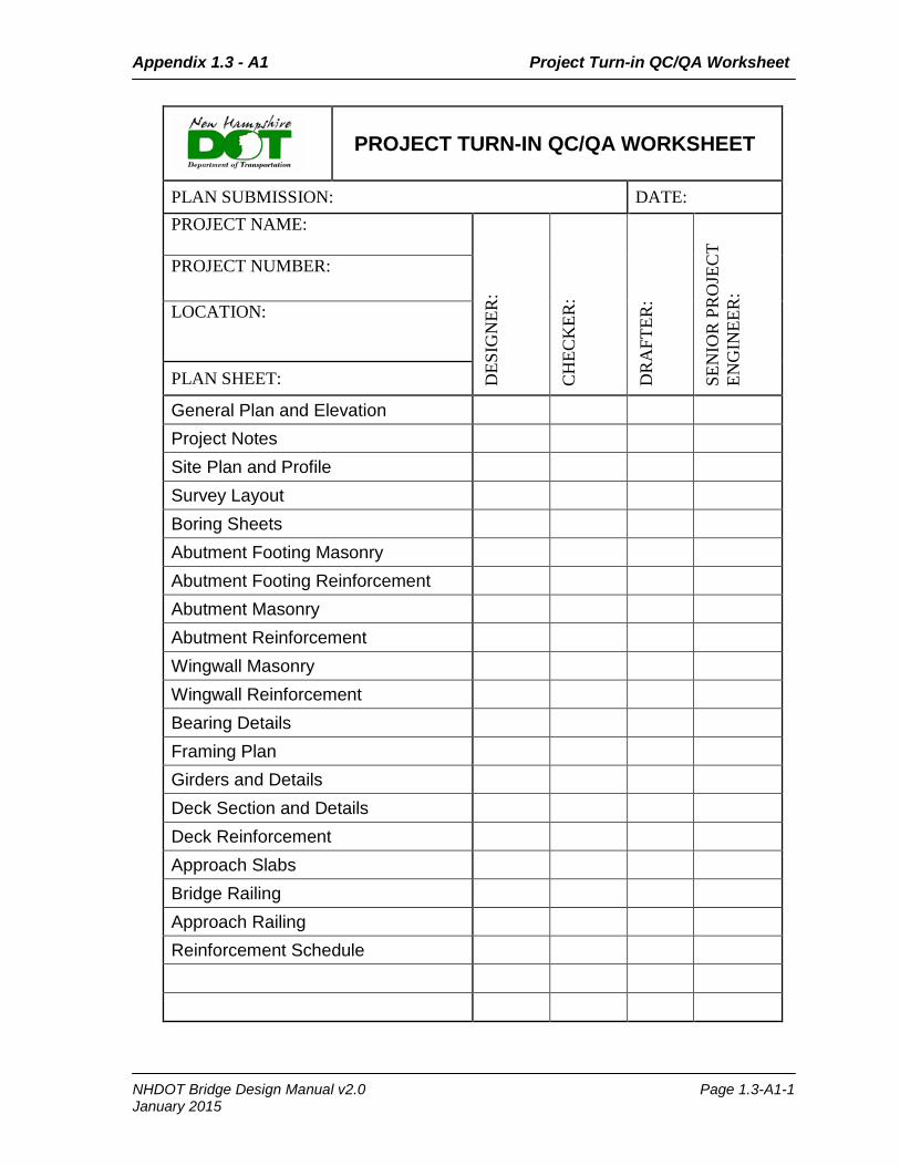
Appendix 1.3 - A1 Project Turn-in QC/QA Worksheet
PROJECT TURN-IN QC/QA WORKSHEET
PLAN SUBMISSION: DATE: PROJECT NAME:
DES
IGN
ER:
CH
ECK
ER:
DR
AFT
ER:
SEN
IOR
PR
OJE
CT
ENG
INEE
R:
PROJECT NUMBER:
LOCATION:
PLAN SHEET:
General Plan and Elevation Project Notes Site Plan and Profile Survey Layout Boring Sheets Abutment Footing Masonry Abutment Footing Reinforcement Abutment Masonry Abutment Reinforcement Wingwall Masonry Wingwall Reinforcement Bearing Details Framing Plan Girders and Details Deck Section and Details Deck Reinforcement Approach Slabs Bridge Railing Approach Railing Reinforcement Schedule
NHDOT Bridge Design Manual v2.0 Page 1.3-A1-1 January 2015

Appendix 1.3 - A1 Project Turn-in QC/QA Worksheet
Page intentionally left blank.
NHDOT Bridge Design Manual v2.0 Page 1.3-A1-2 January 2015
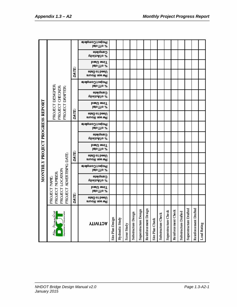
Appendix 1.3 – A2 Monthly Project Progress Report
NHDOT Bridge Design Manual v2.0 Page 1.3-A2-1 January 2015

Appendix 1.3 – A2 Monthly Project Progress Report
Page intentionally left blank.
NHDOT Bridge Design Manual v2.0 Page 1.3-A2-2 January 2015

Appendix 1.3 – A3 Plan File and Tub Location
Bridge Design
Plan File and Tub Location Tub Number Plan File Numbers in Tub: Tub Location (DOT):
1 1 thru 18 (i.e. 1-1-1-1) Basement Storage Room
2 1 thru 15 (i.e. 2-1-1-1) Basement Storage Room
3 1 thru 15 (i.e. 3-1-1-1) Pocket No. 12: D1 thru D16 Pocket No. 13: E1 thru E11
Bridge Design Office
4 1 thru 15 (i.e. 4-1-1-1) Basement Storage Room
5 1 thru 13, and old rail standards Basement Storage Room
6 Discontinued
7
Pocket No. 1 thru 15 Pocket No. 1: A1 thru A20 Pocket No. 2: B1 thru B17 Pocket No. 3: B18 thru B20 and C1 thru C12 Pocket No. 4: (i.e. 4-1-1) Pocket No. 5: (i.e. 5-1-1), etc.
Bridge Design Office
8 16 thru 30 Bridge Design Office
9 31 thru 45 Basement Storage Room
10 46 thru 60 Basement Storage Room 11 61 thru 71 Bridge Design Office
12 72 thru 85 Bridge Design Office
13 86 thru 95 Basement Storage Room 14 96 thru 103 Basement Storage Room
15 104 thru 115 Basement Storage Room
16 116 thru current Bridge Design Office
A - TT (Municipal Bridges -
“Old Town Tub”)
See next page: “Old Town Tub” Plan File Number Chart Basement Storage Room
M1 (Municipal Bridges - “New Town Tub”)
M1-1-1-1 thru current Basement Storage Room
NHDOT Bridge Design Manual v2.0 Page 1.3-A3-1 January 2015

Appendix 1.3 – A3 Plan File and Tub Location
Municipal Plan File Numbers
(“Old Town Tub”)
Tub Number Plan File Numbers in Tub:
A - TT
A1 thru A40 O1 thru O25
A41 thru A80 P1 thru P30
B1 thru B47 P31 thru P37
B49 thru B102 Q1 thru Q27
C0 thru C50 R1
C51 thru C106 S1-1
D1 thru D40 S1-2
E1 thru E49 T1 thru T19
F1 thru F20 U1 thru U10
F21 thru F34 U11 thru U35
G1 thru G17 V1 thru V5
G18 thru G36 W1-1
H1 thru H42 W1-2
I1 thru I34 X-1-1 thru X-1-12
J1 thru J30 TT1 1-27
K1 thru K25 TT1 1-17
K26 thru K56 TT1 1-16
L1 thru L30 TT1 1- 8
L31 thru L62 TT2 1- 8
M1 thru M20 TT2 1
M21 thru M44 Private 1-1-1
N1 thru N17 Standard Plans
N18 thru N34
NHDOT Bridge Design Manual v2.0 Page 1.3-A3-2 January 2015
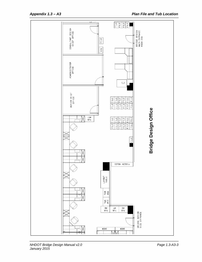
Appendix 1.3 – A3 Plan File and Tub Location
Brid
ge D
esig
n O
ffice
TUB
#16
NHDOT Bridge Design Manual v2.0 Page 1.3-A3-3 January 2015

Appendix 1.3 – A3 Plan File and Tub Location
NHDOT Basement Storage
5
NHDOT Bridge Design Manual v2.0 Page 1.3-A3-4 January 2015

Appendix 1.3 – A4 Incomplete Submittal for Documentation
NHDOT Bridge Design Manual v2.0 Page 1.3-A4-1 January 2015

Appendix 1.3 – A4 Incomplete Submittal for Documentation
Page intentionally left blank.
NHDOT Bridge Design Manual v2.0 Page 1.3-A4-2 January 2015

Appendix 1. 3 – A5 Bridge Design Software Applications
Bureau of Bridge Design
Software Applications from Other Sources Program Description Author Location AISC Search Utility Dimensions and properties of steel
shapes from 1873 to 2003. AISC S:\Bridge-Design\DESIGN\
PROGRAMS
BOXCAR Box culvert analysis and reinforcement design.
ACPA S:\Bridge-Design\DESIGN\ PROGRAMS
BRASS Girder (LRFD)
Bridge rating and analysis of structural systems for steel and concrete.
WYDOT S:\Bridge-Design\DESIGN\ PROGRAMS
COM624P, Group, Lpile
Analizes lateral load capacity of piled foundations.
Ensoft, Inc. Local C Drive
CONSPAN (LRFD & LFD)
Fully integrated analysis and design software for simple span and multiple span precast, prestressed concrete beams.
LEAP Software, Bentley
C:\Program Files\Bentley\ CONSPAN Rating\cnla.exe
CSI Bridge (SAP2000)
Defines complex bridge geometries, boundary conditons and load cases for steel or concrete bridges
Computers & Structures, Inc.
Local C Drive
GAGeom Georgia Geometry - (aka Georgia Skew) - determines elevations and coordinates (based on a local coordinate system) for bridges of any geometry (including curves).
Georgia S:\Bridge-Design\DESIGN\ PROGRAMS
GTStrudl Finite element analysis. CASE Center Georgia Institute of Technology
Local C drive
HEC-RAS Open channel flow analysis including bridge backwater analysis.
US ACOE Local C drive
MathCAD "Electronic scratchpad" (similar to a spreadsheet)
PTC Local C drive
LRFD LL Distribution Factors
Excel program calculates the LRFD LL Distribution Factors
TXDOT S:\Bridge-Design\DESIGN\ PROGRAMS
Merlin-Dash Steel girder analysis & design University of Maryland
S:\Bridge-Design\DESIGN\ PROGRAMS
MicroStation CADD package Bentley Local C Drive
MSD Draws moment, shear, and deflection diagrams.
S:\Bridge-Design\DESIGN\ PROGRAMS
MX Roadway Design Bentley Local C drive
Pontis Network level Bridge Inventory Management System
AASHTO Local C drive
NHDOT Bridge Design Manual v2.0 Page 1.3-A5-1 January 2015

Appendix 1. 3 – A5 Bridge Design Software Applications
Bureau of Bridge Design In-House Software Applications
Program Description Author Location Bridge Shoes Excel spreadsheet designs
elastomeric bearing pad. S:\Bridge-Design\DESIGN\
PROGRAMS\Elastomeric-Bearings
Excel and Mathcad programs for steel bearing design.
S:\Bridge-Design\DESIGN\ PROGRAMS\Steel Bearings\
Bridge Exp Joints Matchcad programs for compression and strip seal design.
S:\Bridge-Design\DESIGN\ PROGRAMS\BRIDGE EXP JOINTS\
Cofferdam Excel spreadsheet analyzes cantilevered and anchored sheetpile walls. These spreadsheets analyze various configurations of sheeted cofferdams.
Bob Juliano, P.E.
S:\Bridge-Design\DESIGN\ PROGRAMS\Cofferdam\ Unchecked\Sheetpile.xls
Excel spreadsheet analyzes cantilevered and anchored sheetpile walls.
Bill Saffian, P.E.
S:\Bridge-Design\DESIGN\ PROGRAMS\Cofferdam\ Unchecked\Sht Pile 2006_v1.1.xls
Concrete Slab Excel spreadsheet designs a concrete slab.
Bill Saffian, P.E.
S:\Bridge-Design\DESIGN\ PROGRAMS\Concrete Slab\
Deck Mathcad programs for deck design. S:\Bridge-Design\DESIGN\ PROGRAMS\Deck\
Excel spreadsheet designs a LFRD deck.
Bill Saffian, P.E.
S:\Bridge-Design\DESIGN\ PROGRAMS\Deck\Unchecked\LRFD-DECK v1_8.xls
Mathcad programs for LFD & LRFD full depth deck panel design.
S:\Bridge-Design\DESIGN\ PROGRAMS\Deck\Unchecked\Full Depth Deck Panels
Deck Falsework Excel spreadsheet for deck overhang falsework design.
Bob Juliano, P.E.
S:\Bridge-Design\DESIGN\ PROGRAMS\Deck Falsework\DeckFalse.xls
Excel spreadsheet for deck overhang falsework design.
Bill Saffian, P.E.
S:\Bridge-Design\DESIGN\ PROGRAMS\Deck Falsework\DeckFalsework Design.xls
Frame Excel spreadsheet for frame design Bill Saffian, P.E.
S:\Bridge-Design\DESIGN\ PROGRAMS\FRAME\ Unchecked\FEM_V1_5.xls
DOS and Excel spreadsheets for frame design
David Scott, P.E.
S:\Bridge-Design\DESIGN\ PROGRAMS\FRAME\ Approved\
Geometry Georgia DOS program analyzes geometry
S:\Bridge-Design\DESIGN\ PROGRAMS\Geometry\ Approved\GAGEOM\
Excel spreadsheet analyzes bridge geometry
Bill Saffian, P.E.
S:\Bridge-Design\DESIGN\ PROGRAMS\Geometry\ Unchecked\BridgeGeometry V7_9.xls
NHDOT Bridge Design Manual v2.0 Page 1.3-A5-2 January 2015

Appendix 1. 3 – A5 Bridge Design Software Applications
Bureau of Bridge Design In-House Software Applications
Program Description Author Location Hydraulics Excel spreadsheet determines the
bridge hydraulic opening Bill Saffian, P.E.
S:\Bridge-Design\DESIGN\ PROGRAMS\Hydraulics\ Unchecked\Bridge Hydraulic Opening v1_0.xls
LL & DL Shear-Moment
Excel spreadsheet determines shear and moment for up to 4 spans.
Bill Saffian, P.E.
S:\Bridge-Design\DESIGN\ PROGRAMS\LL & DL Shear-Moment\ Unchecked\LL-4span deck with cantilever v1_6.xls
LRFD LL Distribution Factor
Excel spread sheet determines LRFD Distribution Factors
Bill Saffian, P.E.
S:\Bridge-Design\DESIGN\ PROGRAMS\LRFD LL Distribution Factor\ Unchecked\LRFD Distribution Factor I Girder v1_0.xls
NEBT Mathcad program for designing New England Bulb Tee Prestress/Precast Girder
David Scott, P.E.
S:\Bridge-Design\DESIGN\ PROGRAMS\NEBT\Unchecked\NEBT design.mcd
Pier Loads Excel spread sheet that combines LRFD loads on a pier
Bill Saffian, P.E.
S:\Bridge-Design\DESIGN\ PROGRAMS\Pier Loads\ Unchecked\Pier_Load v1_7.LRFD.xls
Rebar
Spreadsheet calculates rebar weights. Also creates a rebar sheet for plans.
Steven Ireland
S:\ Bridge-Design\DESIGN\ PROGRAMS\REBAR\ Approved\Engsum2k.xls
Excel spreadsheet determines total J-bar length
Kevin Diagle S:\ Bridge-Design\DESIGN\ PROGRAMS\REBAR\Unchecked\rebar-J(N3) length.xls
Rect. Concrete Beam Design (WSD)
Spread sheet for designing a concrete rectangular beam using Working Stress Design
Angela Hubbard
S:\Bridge-Design\DESIGN\ PROGRAMS\Unchecked\ WSD rect. concrete beam.xls
Ret_Wall WSD Program analyzes retaining walls and abutments.
Bob Juliano, P.E.
S:\ Bridge-Design\DESIGN\ PROGRAMS\ Ret_Wall\\Approved\ RW2\Rw2.bat
Mathcad program analyzes retaining wall for LRFD
Bill Saffian, P.E.
S:\ Bridge-Design\DESIGN\ PROGRAMS\ Ret_Wall\\Unchecked\ Wing_Spread_Ftg.v4_0.xmcd
Ret_Wall_LRFD-MathCAD
Mathcad program for analyzing retaining walls
Samantha Fifield, P.E.
S:\Bridge-Design\DESIGN\ PROGRAMS\Ret_Wall_LRFD-MathCAD \Unchecked\
Scour Mathcad worksheet to calculate scour caused by a contraction (narrowing at bridge opening or pier placed in the channel or both).
David L. Scott, P.E.
S:\BridgeDesign\DESIGN\ PROGRAMS\Scour\Unchecked\SCOUR.MCD
NHDOT Bridge Design Manual v2.0 Page 1.3-A5-3 January 2015

Appendix 1. 3 – A5 Bridge Design Software Applications
Bureau of Bridge Design In-House Software Applications
Program Description Author Location Shear Connectors Excel spreadsheet that designs shear
connector layout for LRFD Bill Saffian, P.E.
S:\BridgeDesign\DESIGN\ PROGRAMS\Shear Connector\Unchecked\ V-ConnectorLRFD v1_2.xls
Excel spreadsheet that designs shear connector layout for LRFD
Dan Taylor, P.E.
S:\BridgeDesign\DESIGN\ PROGRAMS\Shear Connector\Unchecked\ Shear Connectors.xls
Sign DOS program analyzes loads on sign structure and calculates maximum moments for bottom of footing.
Bob Juliano, P.E.
S:\Bridge-Design\DESIGN\ PROGRAMS\SIGN\ Approved\SIGN.EXE
Excel program analyzes load on sign structure and designs footing
Bill Saffian, P.E. & ABH & JAS
S:\Bridge-Design\DESIGN\ PROGRAMS\SIGN\Unchecked\ OHSS_2009v1_7 and SignFoot-2009_v1
Spanwire Calculates the tension of a spanwire. ACJ & JAT S:\Bridge-Design\DESIGN\ PROGRAMS\SPANWIRE.xls
Steel_Beam Mathcad and Excel programs to design steel splice
S:\Bridge-Design\DESIGN\ PROGRAMS\SIGN\ Unchecked\Splice.mcd and SPLICE.xls
Excel program calculates section properties and stresses
LMS & Bill Saffian, P.E
S:\Bridge-Design\DESIGN\PROGRAMS\SIGN\Unchecked\2BEAM.xls & Sectn Prop Comp_Gdr v1_2.xls
VERTCURV Excel program calculates vertical curves
Angela Hubbard
S:\Bridge-Design\DESIGN\ PROGRAMS\VERTCURV\ Unchecked\
NHDOT Bridge Design Manual v2.0 Page 1.3-A5-4 January 2015

Appendix 1.3 – A6 Bridge Design Software Applications Cover Sheet
Bureau of Bridge Design
Software Applications Cover Sheet Program Name, Date, Version No.:
Location:
Description:
Directions for Use:
NHDOT Bridge Design Manual v2.0 Page 1.3-A6-1 January 2015

Appendix 1.3 – A6 Bridge Design Software Applications Cover Sheet
Page intentionally left blank.
NHDOT Bridge Design Manual v2.0 Page 1.3-A6-2 January 2015

Appendix 1.3 – A7 Examples of Contract Plan Revisions
NHDOT Bridge Design Manual v2.0 Page 1.3-A7-1 January 2015

Appendix 1.3 – A7 Examples of Contract Plan Revisions
NHDOT Bridge Design Manual v2.0 Page 1.3-A7-2 January 2015

Appendix 1.4 - A1 Project Development Schedule
NHDOT Bridge Design Manual v2.0 Page 1.4-A1-1 January 2015
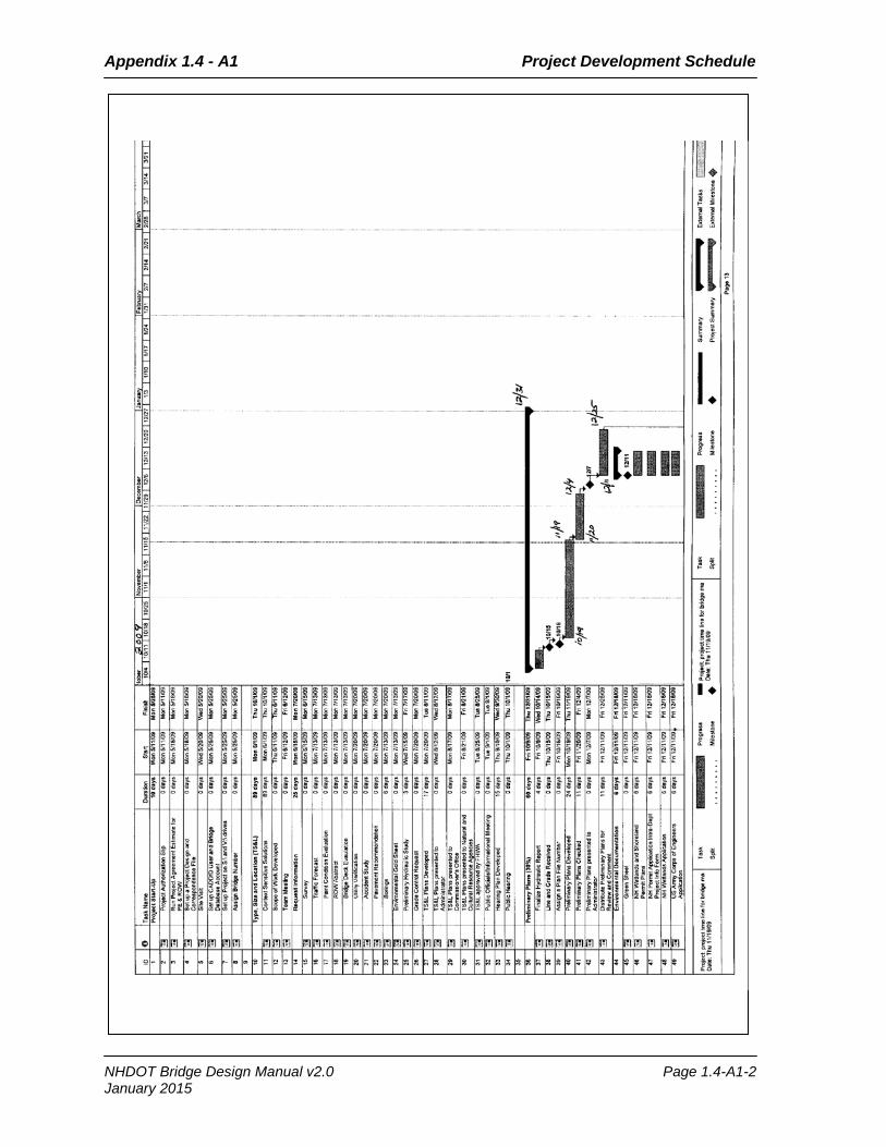
Appendix 1.4 - A1 Project Development Schedule
NHDOT Bridge Design Manual v2.0 Page 1.4-A1-2 January 2015

Appendix 1.4 - A1 Project Development Schedule
NHDOT Bridge Design Manual v2.0 Page 1.4-A1-3 January 2015

Appendix 1.4 - A1 Project Development Schedule
NHDOT Bridge Design Manual v2.0 Page 1.4-A1-4 January 2015

Appendix 1.4 - A1 Project Development Schedule
NHDOT Bridge Design Manual v2.0 Page 1.4-A1-5 January 2015

Appendix 1.4 - A1 Project Development Schedule
NHDOT Bridge Design Manual v2.0 Page 1.4-A1-6 January 2015

Appendix 1.4 – A2 Procedure for Project Salvage Credits
NHDOT Bridge Design Manual v2.0 Page 1.4-A2-1 January 2015

Appendix 1.4 – A2 Procedure for Project Salvage Credits
NHDOT Bridge Design Manual v2.0 Page 1.4-A2-2 January 2015

Appendix 1.4 – A3 Guidelines for Use of 1000 Items
NHDOT Bridge Design Manual v2.0 Page 1.4-A3-1 January 2015
Appendix 1.4 – A3 Guidelines for Use of 1000 Items
NHDOT Bridge Design Manual v2.0 Page 1.4-A3-2 January 2015

Appendix 1.4 – A4 Director Data Sheet Project Explanation Guidelines
NHDOT Bridge Design Manual v2.0 Page 1.4-A4-1 January 2015

Appendix 1.4 – A4 Director Data Sheet Project Explanation Guidelines
NHDOT Bridge Design Manual v2.0 Page 1.4-A4-2 January 2015

Appendix 1.5 – A1 Person Hours Project Log
NHDOT Bridge Design Manual v2.0 Page 1.5-A1-1 January 2015

Appendix 1.5 – A1 Person Hours Project Log
NHDOT Bridge Design Manual v2.0 Page 1.5-A1-2 January 2015
January 2015 – v 2.0

Page intentionally left blank.

Appendix 1.1 – C1 Record of Manual Revisions
Record of Manual Revisions
Revision Number
Memorandum Number
Date of Revision/ Memorandum
Entry Date
Entered By (Initials)
NHDOT Bridge Design Manual v2.0 Page 1.1-C1-1 January 2015

Appendix 1.1 – C1 Record of Manual Revisions
Page intentionally left blank.
NHDOT Bridge Design Manual v2.0 Page 1.1-C1-2 January 2015


![FILTRO OLIO/OIL FILTER[10-] 10-00-003 10-00-010 - Lirostalirosta.lt/wp-content/uploads/2016/04/A7.pdf · chery a1 1.3 chery chance m11 1.5 i sed chery qq6 1.3 chrysler grand voyager](https://static.fdocuments.us/doc/165x107/5b5b80f37f8b9a24038ebf6b/filtro-oliooil-filter10-10-00-003-10-00-010-chery-a1-13-chery-chance.jpg)