James D. Rotunno
60
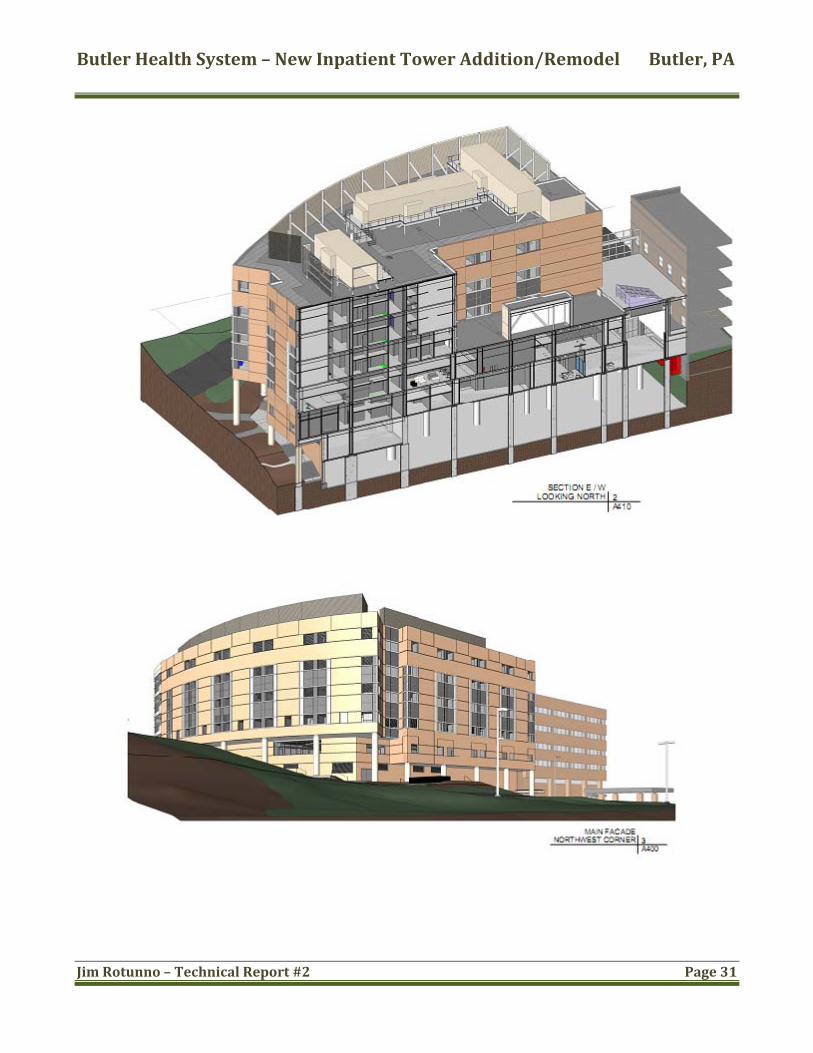
Butler Memorial Hospital Butler, PA Architects Rendering James D. Rotunno Technical Report #2 Floor System Alternatives Structural Option Advisor: Dr. Ali Memari Due October 28 th , 2009
Transcript of James D. Rotunno

Butler Memorial Hospital
Butler, PA
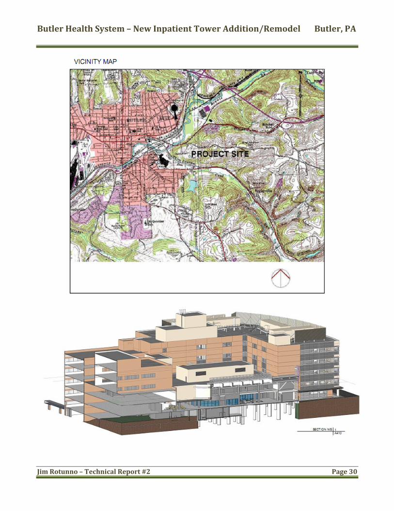
Architects Rendering
James D. Rotunno
Technical Report #2
Floor System Alternatives
Structural Option
Advisor: Dr. Ali Memari
Due October 28th, 2009
Butler Health System – New Inpatient Tower Addition/Remodel Butler, PA
Jim Rotunno – Technical Report #2 Page 2
Table of Contents
Executive Summary: .............................................................................................................................. 4
Introduction: ............................................................................................................................................. 5
Structural System: .................................................................................................................................. 6
Existing System: ................................................................................................................................... 6
Design Standards & Codes: For all four design cases .......................................................... 9
Fire Protection & Ratings: ............................................................................................................... 9
Design Load Summary: .................................................................................................................. 10
Non‐composite steel beam construction: .................................................................................. 13
Gravity Loads: .................................................................................................................................... 16
Conclusions: ....................................................................................................................................... 16
Concrete two‐way flat slab with drop panels: ......................................................................... 17
System description: ......................................................................................................................... 18
System Components: ...................................................................................................................... 18
System Loading & Deflection Criteria: .................................................................................... 20
Advantages: ........................................................................................................................................ 21
Disadvantages: .................................................................................................................................. 21
System Conclusions: ....................................................................................................................... 22
Precast hollow plank concrete slabs on steel beams: .......................................................... 22
System Description: ........................................................................................................................ 22

Butler Health System – New Inpatient Tower Addition/Remodel Butler, PA
Jim Rotunno – Technical Report #2 Page 3
Advantages: ........................................................................................................................................ 24
Disadvantages: .................................................................................................................................. 24
System Conclusions: ....................................................................................................................... 24
Summary: ................................................................................................................................................ 25
Conclusions: ........................................................................................................................................... 26
Appendix: A ............................................................................................................................................ 28
Appendix B .............................................................................................................................................. 32
Appendix C .............................................................................................................................................. 37
Appendix D ............................................................................................................................................. 42
Appendix E .............................................................................................................................................. 56
Butler Health System – New Inpatient Tower Addition/Remodel Butler, PA
Jim Rotunno – Technical Report #2 Page 4
Executive Summary:
In this second technical report for The Butler Health System – New Inpatient Tower Addition and Remodel the existing floor system and three alternative system designs are investigated and analyzed. These four systems are then compared side‐by‐side with multiple general conditions and criteria to determine which systems would be a good fit for the structure and which ones deserve
is. further consideration and analys
The floor systems proposed are: 1. Existing‐ composite steel beam with lightweight concrete 2. Non‐composite steel beam construction with one additional beam per bay 3. Concrete two‐way flat‐slab with drop panels 4. Precast hollow plank concrete slabs on steel beams
A final criteria summary chart is depicted in Figure 2.25 which lists fourteen different aspects. Final conclusions show that the non‐composite steel system has no merit to be considered as an alternative design for this type of structure. The final conclusions also show that the two way flat‐slab with drop panels is a good and viable alternative solution on a general basis. Floor system four is a fair alternative for the existing one.
Systems 3& 4 as listed above both deserve a further analysis with the flat slab eing the better choice. b
Butler Health System – New Inpatient Tower Addition/Remodel Butler, PA
Jim Rotunno – Technical Report #2 Page 5
Introduction: Butler Health System’s new addition consists of two sub grade levels which have limited facade and entrances at ground level on the plan west end of the structure. There are five other at or above grade levels that comprise the bulk of the hospitals general facilities. One more final level, the penthouse level, encompasses the mechanical equipment on the roof top.
The structure is approximately 206,000 square feet with floor to floor heights of 14'‐8” each. It stands at just a little over 100' tall above the highest grade level and is situated on the middle of a hillside. With the exception of the slightly arcing plan north facade the floor plan is quite regular with typical bay sizes being 28' x30'.
Drilled caissons were used for the foundation system which range from 30” – 78” in diameter and reach depths of up to 79'. Grade beams between the caissons on the below grade level areas transfer wall loads to the foundation system and provide interior perimeter walls for the lower levels as well as provide support for the slab on grade at the second level. The superstructure is composed of steel W‐shape members with a steel HSS lateral bracing system. Almost all member connections are shear connections with the exception of a few moment connections at cantilevering beams. These moment connections however do not contribute to the lateral force resisting system.
This report examines the existing floor construction system and three alternative design methods to determine each systems viability and possible implementation into the structure. Factors for this analytical review are system weight, depths, costs, fire ratings, foundation impacts, constructability, changes to the lateral force resisting system, vibration concerns and if each system warrants future consideration for a thesis proposal.
All calculations and designs are purely schematic and are only taking into account a typical bay and therefore are not an exhaustive analysis for each type of floor system.

Butler Health System – New Inpatient Tower Addition/Remodel Butler, PA
Jim Rotunno – Technical Report #2 Page 6
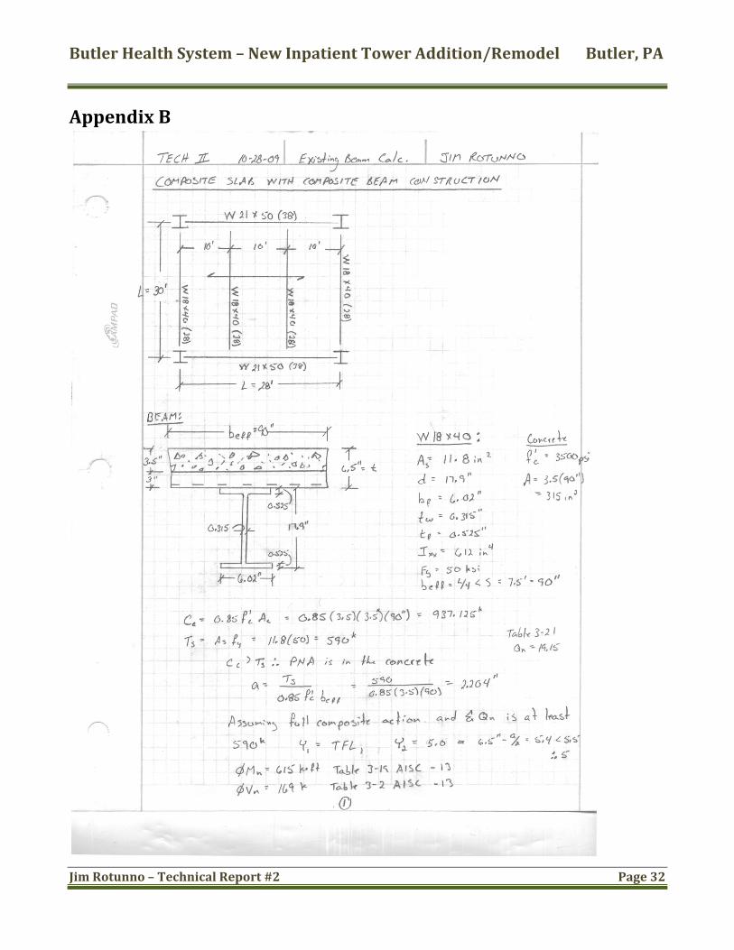
Structural System: Existing System: Existing conditions for the originally designed floor system consists of composite steel decking with lightweight concrete (f'c = 3500psi @28 days). It has 20 gauge steel decking with 3” deep flutes, ¾” diameter 5” long shear studs and an additional 3.5” of concrete. The girders supporting the beams and floor system are typically W21x50, 28' long with 38 shear studs. There are typically four beams per bay including the ones at each column line. The beams are W18x40 evenly spaced at ten foot intervals and are 30 feet long with 28 shear studs each.
Figure 2.1: Third floor framing plan with typical bay shown

Butler Health System – New Inpatient Tower Addition/Remodel Butler, PA
Jim Rotunno – Technical Report #2 Page 7
Figure 2.2: Typical bay to be considered enlarged view

Butler Health System – New Inpatient Tower Addition/Remodel Butler, PA
Jim Rotunno – Technical Report #2 Page 8
Figure 2.3: existing slab & beam/girder conditions
Figure 2.4: Lateral Bracing Elevation
Figure 2.5: Existing slab/deck schedule

Butler Health System – New Inpatient Tower Addition/Remodel Butler, PA
Jim Rotunno – Technical Report #2 Page 9
Design St
2006 IBC 2000 NFPA 101 2006 Guidelines for Design & Construction of Health Care Facilities 1998 Pennsylvania Department of Health Rules and Regulations for Hospitals ASCE 7‐05: for wind, seismic, snow and gravity loads ACI 318‐08: for concrete construction AISC Thirteenth Edition: for steel members United Steel Deck Catalog #303‐16 Copyright 2002 RS Means Square Foot Costs Guide 2008 CRSI Design Handbook 2002 Nitterhouse Concrete Products Inc. design guide Floor deflections limited to: L/360 for construction load L/360 for live load, L/240 total
andards & Codes: For all four design cases
Fire Protection & Ratings:
Figure 2.6: Table from construction documents

Butler Health System – New Inpatient Tower Addition/Remodel Butler, PA
Jim Rotunno – Technical Report #2 Page 10
Design Load Summary: Gravity Loads
Description/location DL/ LL
ASCE 7‐05/ IBC 1607.9 values
HGA’s values
Reduction ava ed ilable/us
Design value
Concrete floors DL 90‐115pcf 115pcf NO/NO 115pcf MEP/partitions/finishes SDL 20‐25psf NO/NO 35psf 1st floor mechanical LL 125psf YES/NO 125psf 2nd floor/ lobby LL 100psf 100psf YES/NO 100psf H spital flooro s LL 40‐80psf 80psf Y ES/YES 80psf Stairs & exits LL 100psf 100psf NO/NO 100psf 5th floor roof LL 115psf NO/NO 115psf Mech. Penthouse floor LL 125psf NO/NO 125psf Elevator Machine roofloor
m LL 125psf YES/NO
Roof top eareas
quipment LL 125psf (or actual
equipment wt.)
NO/NO 125psf
Balconies LL 100psf 100psf Y ES/YES psf Snow LL 24‐30psf 24‐30psf NO/NO 2430psf Figure 2.7
Gravity Loads:
Dead loads for the floor area were determined in technical report 1 and were calculated at 48psf for the lightweight concrete, 7psf for the wide flanges, 3psf for the steel decking, and 35psf for MEP/partitions/finishes. Live loads are 40‐80psf for hospital floors, therefore 80 will be used for calculation purposes and no live load reduction will be taken since there are other areas with larger load criteria
re not permitted. and reductions a
Total DL= 93psf Total LL= 80psf 1.2DL + 1.6 LL = 239.6psf

Butler Health System – New Inpatient Tower Addition/Remodel Butler, PA
Jim Rotunno – Technical Report #2 Page 11
Figure 2.8: Composite steel decking used for existing floor design & non composite beam floor design. Note: f'c= 3000psi for table values, f'c of 3500psi is used in design, therefore these alues will be slightly conservative v
Figure 2.9: Shows the ΦMn (in*k) & the maximum unshored span for a 3span system
The ΦMn value of 79.92 equates to 959ft*k, which is well above the design of Mu=270 ft*k. The design span is equal to 10’ which is below the 11.21' specified.

Butler Health System – New Inpatient Tower Addition/Remodel Butler, PA
Jim Rotunno – Technical Report #2 Page 12
Figure 2.10: Shows the uniform live service loads (NO factors) of combined DL & LL for a 10' span as 195psf which is above the 173psf design value.
Figure 2.11: Shows that the flooring system meets the U.L. designation code as specified in the construction documents with 3.5” LW Concrete. Therefore spray‐on fireproofing is not needed on the underside of the deck as designated by the N.

Butler Health System – New Inpatient Tower Addition/Remodel Butler, PA
Jim Rotunno – Technical Report #2 Page 13
Note: Design calculations for the girder and beam can be found in Appendix B. The calculations vary from those of technical report 1 in the fact that the typical bay was chosen from a different area which used W18x40 non‐cambered unshored beams instead of the W16x26 ¾” cambered beams. Both typical bays are predominating and found on all levels and this is a good check to see how each one performs given the same loading.
Conclusions from the floor analysis show that construction load deflection controlled the beam size for the W16x26 analyzed for technical report #1as well as the size of the W18x50. The reason for using the smaller beams with camber could be that there are depth limitations in that area, which could be a limiting factor for design #2, non‐composite beams with one additional beam per bay.
Noncomposite steel beam construction: The first alternate floor design has the same bay size as that of the existing design. In this configuration I chose to resize the girders and beams to try and get a more even distribution of strength and serviceability requirements. Members will try to be selected so as to minimize depth and still keep costs down. The beams and girders will still have the same lengths and direction. A lighter gage deck will be sed for the shorter span and there will be no composite beam action. u
Figure 2.12: Bay beam layout

Butler Health System – New Inpatient Tower Addition/Remodel Butler, PA
Jim Rotunno – Technical Report #2 Page 14
A 2” LOK‐FLOOR using 22 gage steel and a 3.5” LW concrete topping for a total depth of 5.5” is used in this design. Table values listed below can be found in figures 2.14 – 2.15 ΦMno = 38.29in*k, the factored resisting moment of the composite slab with no shear studs W=43, the weight of the concrete in psf ΦVnt=4970lbs, the factored vertical shear resistance of the composite system Maximum unshored span=7.86 ft, for 3 spans this is the maximum unshored distance
Figure 2.13: Composite steel decking Note: f'c= 3000psi for table values, f'c of 3500psi is used in design, therefore these values will be slightly conservative
Figure 2.14: Composite properties

Butler Health System – New Inpatient Tower Addition/Remodel Butler, PA
Jim Rotunno – Technical Report #2 Page 15
Figure 2.15: Shows the uniform live service loads (NO factors) of combined DL & LL for a 7.5' span as 250psf which is above the 173psf design value.
Figure 2.16: Shows that the flooring system meets the U.L. designation code as specified in the construction documents with 3.5” LW Concrete. Therefore spray‐on fireproofing is not needed on the underside of the deck as designated by the N.

Butler Health System – New Inpatient Tower Addition/Remodel Butler, PA
Jim Rotunno – Technical Report #2 Page 16
Gravity Loads: Dead loads for the floor area are determined from figure 2.14 at 43psf for the lightweight concrete, 1.5psf for the steel decking, and 35psf for MEP/partitions/finishes. Live loads are 40‐80psf for hospital floors, therefore 80 will be used for calculation purposes and no live load reduction will be taken since
as with larger load criteria and reductions are not permitted. there are other are
Total DL= 79.5psf Total LL= 80psf 1.2DL + 1.6 LL = 223.4psf
Floor deflections limited to: L/360 for construction load L/360 for live load, L/240 total
Note: Design calculations for the girder and beam can be found in Appendix C.
Conclusions: The first alternate floor analysis shows that it is not possible to achieve an even use of the member through its strength and serviceability (deflection criteria). Without the use of the composite beam/girder system the members will either have to be deeper or their weight per lineal foot will increase by at least a factor of two. Addressing the depth issue is not a problem for strictly height as there are no code restrictions on floor to floor heights. This does however lead to other issues with an increased ceiling cavity that would require more energy to control, and increase in the amount of fire protection that would be required to protect the structural members. There are also structural concerns to deal with which include increased load on the columns and footings and well as an increase in unbraced lengths both of which would contribute to larger columns. If smaller depths were used there would still be the concern for the above mentioned structural issues. Either way the costs would be the most prohibitive fact. Costs associated with steel tonnage, increased footing sizes, increased connection sizes and number of fasteners, and labor associated with these would all be factors. The composite system is a better overall system.

Butler Health System – New Inpatient Tower Addition/Remodel Butler, PA
Jim Rotunno – Technical Report #2 Page 17
Concrete twoway flat slab with drop panels: Alternate floor design number two will utilize the same bay size and configuration as the existing structure. The column layout will remain the same (see figure 2.17 for details), but column sizes will be increased due to the additional loading and type of material used, which will be reinforced concrete. In this design all strength and serviceability requirements will be met while trying to achieve a smaller floor to floor height with the least depth slab and drop panels. A design aid from CRSI 2002 (Figure 2.21) was used to compare hand calculations against tabulated values after an initial floor thickness had been determined using ACI Table 9.5(c).
Figure 2.17: Existing and proposed column layout Note: Footing & column sizes may need to be increased
Column Analyzed
Butler Health System – New Inpatient Tower Addition/Remodel Butler, PA
Jim Rotunno – Technical Report #2 Page 18
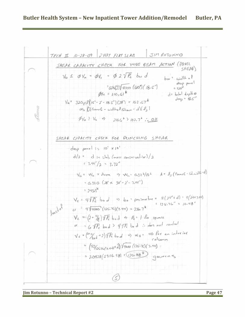
System description: This system is an all concrete flat slab with standard size reinforcing, generally #5. Each floor level will need to be formed and shored and then reshored after stripping forms until the concrete reaches its 28day field strength. The system can have edge beams to help carry façade loads and transfer them to the columns; this report however will only consider the inside bays. The system is based on the criteria that the columns carry the entire load from the slab and punching shear will most likely control the thickness and design.
An assumption for the design of this type of system is that the Direct Design Method is going to be used. The actual layout of the current building does not meet all of the requirements for this assumption; therefore, the Equivalent Frame Method should be used. As stated in the start of this report this is not an exhaustive analysis and only one interior bay is being compared so the Direct Design Method will be utilized for simplicity.
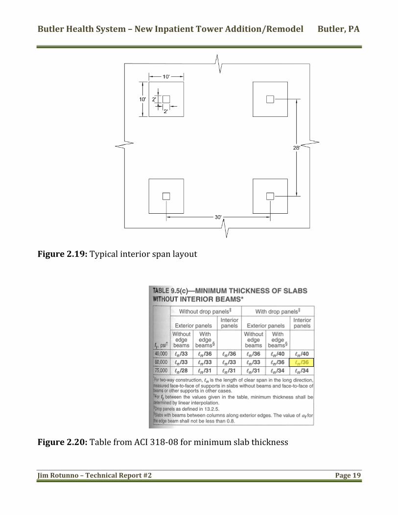
To achieve preliminary slab and drop panel thicknesses the 2002 CRSI Design Handbook was used. A minimum slab thickness was first determined using ACI 318‐08 §9.5 Table 9.5(c). See figure 2.19 for layout. Calculations are presented in Appendix D.
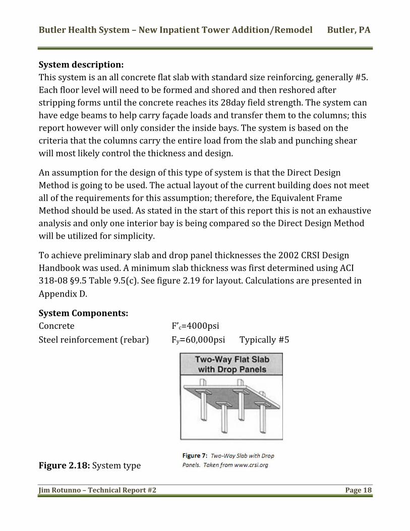
System Components: Concrete F’c=4000psi Steel reinforcement (rebar) Fy=60,000psi Typically #5
Figure 2.18: System type
Butler Health System – New Inpatient Tower Addition/Remodel Butler, PA
Jim Rotunno – Technical Report #2 Page 19
igure 2.19: Typical interior span layout F
Figure 2.20: Table from ACI 318‐08 for minimum slab thickness

Butler Health System – New Inpatient Tower Addition/Remodel Butler, PA
Jim Rotunno – Technical Report #2 Page 20
Figure 2.21: Table from CRSI 2002, to obtain preliminary sizes along with figure 2.20. These figures are for 30' square bays (designed is 30'x28'), therefore numerical values should be conservative.
System Loading & Deflection Criteria: Gravity Loads: Dead loads for the floor area are 125psf for normal weight reinforced concrete @ 10”, and 35psf for MEP/partitions/finishes. Live loads are 40‐80psf for hospital floors, therefore 80 will be used for calculation purposes and no live load reduction will be taken since there are other areas with larger load
tions are not permitted. criteria and reduc
Total DL= 160psf Total LL= 80psf 1.2DL + 1.6 LL = 320psf
Floor deflection calculations are not required since ACI 9.5.3 Table 9.5c was used.
Butler Health System – New Inpatient Tower Addition/Remodel Butler, PA
Jim Rotunno – Technical Report #2 Page 21
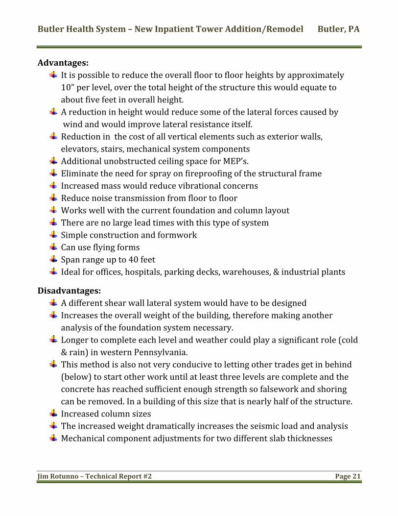
Advantages: It is possible to reduce the overall floor to floor heights by approximately 10” per level, over the total height of the structure this would equate to about five feet in overall height.
by A reduction in height would reduce some of the lateral forces caused wind and would improve lateral resistance itself.
r walls, Reduction in the cost of all vertical elements such as exterioelevators, stairs, mechanical system components
Additional unobstructed ceiling space for MEP’s. tructural frame Eliminate the need for spray on fireproofing of the s Increased mass would reduce vibrational concerns Reduce noise transmission from floor to floor yout Works well with the current foundation and column la his type of system There are no large lead times with t formwork Simple construction and Can use flying forms Span range up to 40 feet Ideal for offices, hospitals, parking decks, warehouses, & industrial plants
Disadvantages: A different shear wall lateral system would have to be designed Increases the overall weight of the building, therefore making another analysis of the foundation system necessary.
Longer to complete each level and weather could play a significant role (cold& rain) in western Pennsylvania.
This method is also not very conducive to letting other trades get in behind (below) to start other work until at least three levels are complete and the
fficient enough strength so falsework and shoring .
concrete has reached sucan be removed. In a building of this size that is nearly half of the structure
Increased column sizes sis The increased weight dramatically increases the seismic load and analy Mechanical component adjustments for two different slab thicknesses

Butler Health System – New Inpatient Tower Addition/Remodel Butler, PA
Jim Rotunno – Technical Report #2 Page 22
System Conclusions: Costs and associated construction time frames would be the two biggest factors affecting whether or not this system should be used. From the list of advantages on the previous page it can be seen that this system is a good viable solution. A cost analysis of savings due to the advantages such as no spray on fireproofing, lower material and labor costs, and less MEP clashes due to more open space would have to be compared to the additional costs of increased foundation bearing and construction schedule timelines as discussed earlier. Another seismic analysis would have to be done and determined if this might control. Note: Values obtained for this system taken from CRSI Found in Figure 2.21 do not match the calculated numerical values found in Appendix D. Possible reasons for the differences could be 1) Bay sizes in the table are 30' x 30', calculated is 28' x 30' 2) Calculated moments do not include the moment due to the increased size of the drop panels, and 3) The table values may be upsizing the rebar to account for the need for additional shear reinforcement instead of adding additional bars.
Precast hollow plank concrete slabs on steel beams:
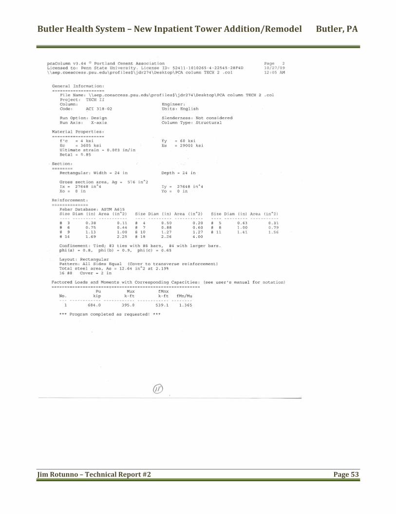
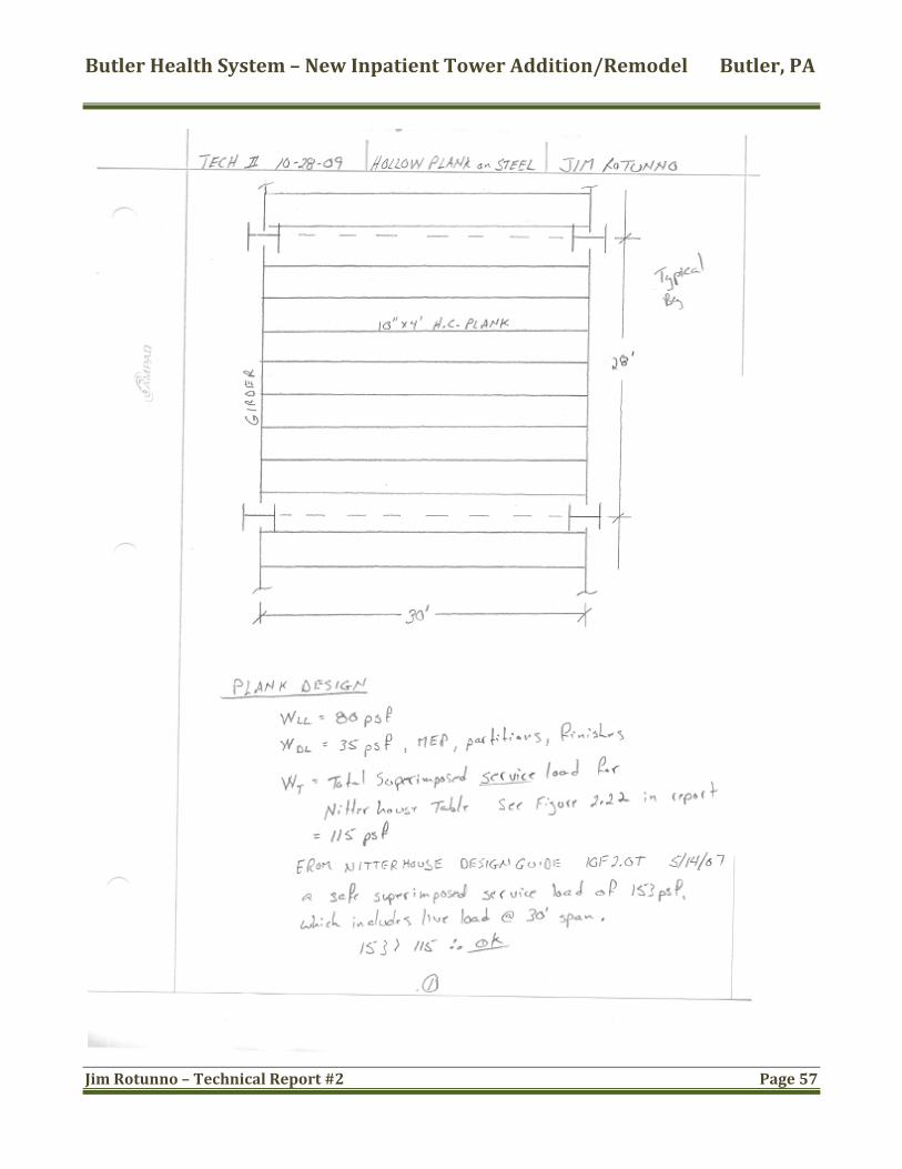
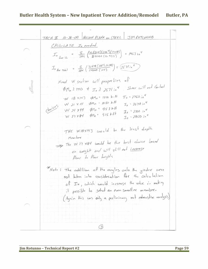
System Description: The idea behind the use of this system is to reduce the overall floor depth, while trying to develop a quicker to install and less expensive system. For the purpose of this design Nitterhouse Concrete Products Inc. published load tables with the 10”x4’ hollow core plank with 2” topping with .5”Ø 270K Lo‐relaxation strand will be used for the floor decking. Typically the planks are placed on top of the steel members and the joints are grouted along with the topping keeping the floor system as a rigid diaphragm and the ability to use the existing lateral system. However, to cut down on total system height a wide flange will be designed to carry the moment and more importantly control the deflection. To achieve this, a section will be selected and an angle with the long leg placed out will be secured to the girder to carry the planks. (See figure 2.22 for details). The angle leg will have to be longer than ½ of the top flange of the supporting member to be able to place and support the plank.

Butler Health System – New Inpatient Tower Addition/Remodel Butler, PA
Jim Rotunno – Technical Report #2 Page 23
Figure 2.22: Modified wide flange to reduce depth
A better way to achieve this would be to use a modified castellated section with a shorter top flange that can resist the applied moments and control the deflections o within acceptable limits. (See figure 2.23 & 2.24 for details) t
Figures 2.23 & 2.24: Modified castellated sections
The infill beams used in the existing design are eliminated except for the beams between the columns. These beams are not used in the gravity load system and therefore will not be analyzed here.

Butler Health System – New Inpatient Tower Addition/Remodel Butler, PA
Jim Rotunno – Technical Report #2 Page 24
Advantages: Easy & fast to install The lateral system can still be utilized ady at usable capacity No formwork required and concrete slabs are alrewhen they arrive
No intermediate beams in interior of bays needed Can be installed in any type of weather mediately Other trades can start work underneath almost im Additional unobstructed ceiling space for MEP’s. Meets or exceeds floor fireproofing requirements led cavities Reduce noise transmission from floor to floor through baff d column layout Can work with the current foundation an No increase in floor to floor heights Reduces overall weight of the structure
Disadvantages: Large lead times with this type of system Girders and columns would need fireproofing Much more efficient and cost effective at shorter spans requirements Column spacing may have to be reduced, increasing footing Floor penetrations must be well coordinated with the slab designer/manufacture
System Conclusions: The advantages outweigh the disadvantages for this system if the girders that support the loading can be designed and manufactured at a cost that could be offset in time and labor savings as well as the need for no intermediate beams.

Butler Health System – New Inpatient Tower Addition/Remodel Butler, PA
Jim Rotunno – Technical Report #2 Page 25
Summary: Floor Comparison Summary Table
igure 2.25: Comparison summary
F
d
Existing Steel Concrete Precast hollowcoreComposite Steel NonComposite Twoway concrete planks
Flatslab on steel beams
System weight (psf) 58 63 125 75Slab depth (in) 6.5 5.5 10 10Total depth (in) 28 32.5 18.5 27Column size W14 W14 24x24 W14Fire rating (hr) 2 2 3 2Additional Fire Proofing required Yes Yes No YesColumn (cost/V.L.Ft) 161.20 1 5
9.15
No
Yes
Yes
Goo
85.6 105.00 161.20Material (cost/sq.ft) 13.95 19.05 8.20 8.45Labor (cost/sq.ft) 6.10 8.70 2.05Total (cost/sq.ft) 181.25 213.40 122.35 171.70Foundation impact None Minimal Moderate NoneConstructability Easy Easy Moderate EasyVibration concerns Some Some SomeLateral force resisting system changesAlternative YesAdditional study Yes Yes
Floor systemsFloor System Comparison of a Typical Bay
Criteria
N/A No No
N/A NoN/A No
Fair
Poor

Butler Health System – New Inpatient Tower Addition/Remodel Butler, PA
Jim Rotunno – Technical Report #2 Page 26
Conclusions: By comparing the three alternate floor systems to the existing composite slab and composite beam system a determination can be made if each system is a viable option to replace the existing system or at least a good candidate for further analysis.
Alternate system one, the non‐composite steel beam and steel column system, has no apparent advantages over the existing design in respect to any of the criteria listed in Figure 2.25 and is therefore not a candidate for future analysis.
Figure 2.25 shows that while the two way flat‐slab with drop panels may have a significant impact on the foundation system with respect to bearing capacity, the potential cost savings as discussed earlier in the system conclusions could very well out weigh this impact. As discussed with the architect this was the initial design intent for the structure before the geotechnical report came in. The increased time in the foundation completion due to the deep socketed piers did not allow for the increased time for superstructure completion; therefore, a quicker to install steel frame with composite action was decided on. This would still be a good choice for an alternate system if it were not for this fact.
The third alternate design of the precast hollow core planks recessed down into the girders appears to also be a fair to somewhat reasonable design if a cost analysis as mentioned in the system conclusions shows that it would have minimal impact. All other aspects of the design criteria shown in Figure 2.25 are relatively comparable in numerical values. If a girder can be manufactured to carry the required moment at the larger span economically this would be a fair candidate for further study.

Butler Health System – New Inpatient Tower Addition/Remodel Butler, PA
Jim Rotunno – Technical Report #2 Page 27
This Page Left Blank Intentionally

Butler Health System – New Inpatient Tower Addition/Remodel Butler, PA
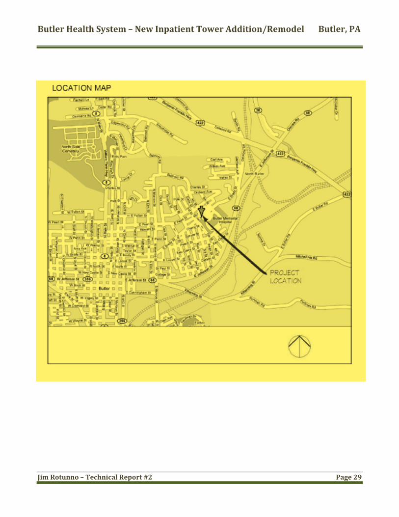
A ppendix: A
View looking from magnetic north
Jim Rotunno – Technical Report #2 Page 28
Butler Health System – New Inpatient Tower Addition/Remodel Butler, PA
Jim Rotunno – Technical Report #2 Page 29
Butler Health System – New Inpatient Tower Addition/Remodel Butler, PA
Jim Rotunno – Technical Report #2 Page 30
Butler Health System – New Inpatient Tower Addition/Remodel Butler, PA
Jim Rotunno – Technical Report #2 Page 31
Butler Health System – New Inpatient Tower Addition/Remodel Butler, PA
Jim Rotunno – Technical Report #2 Page 32
Appendix B

Butler Health System – New Inpatient Tower Addition/Remodel Butler, PA
Jim Rotunno – Technical Report #2 Page 33

Butler Health System – New Inpatient Tower Addition/Remodel Butler, PA
Jim Rotunno – Technical Report #2 age 34 P

Butler Health System – New Inpatient Tower Addition/Remodel Butler, PA
Page 35 Jim Rotunno – Technical Report #2

Butler Health System – New Inpatient Tower Addition/Remodel Butler, PA
Jim Rotunno – Technical Report #2 Page 36
This Page Left Blank Intentionally

Butler Health System – New Inpatient Tower Addition/Remodel Butler, PA
Jim Rotunno – Technical Report #2 Page 37
Appendix C

Butler Health System – New Inpatient Tower Addition/Remodel Butler, PA
Jim Rotunno – Technical Report #2 Page 38

Butler Health System – New Inpatient Tower Addition/Remodel Butler, PA
Jim Rotunno – Technical Report #2 Page 39

Butler Health System – New Inpatient Tower Addition/Remodel Butler, PA
Jim Rotunno – Technical Report #2 Page 40

Butler Health System – New Inpatient Tower Addition/Remodel Butler, PA
Jim Rotunno – Technical Report #2 Page 41
This Page Left Blank Intentionally

Butler Health System – New Inpatient Tower Addition/Remodel Butler, PA
Jim Rotunno – Technical Report #2 Page 42
Appendix D
able taken from ACI 216.1 ‐ 07
T

Butler Health System – New Inpatient Tower Addition/Remodel Butler, PA
Jim Rotunno – Technical Report #2 Page 43

Butler Health System – New Inpatient Tower Addition/Remodel Butler, PA
Jim Rotunno – Technical Report #2 Page 44

Butler Health System – New Inpatient Tower Addition/Remodel Butler, PA
Jim Rotunno – Technical Report #2 Page 45

Butler Health System – New Inpatient Tower Addition/Remodel Butler, PA
Jim Rotunno – Technical Report #2 Page 46
Butler Health System – New Inpatient Tower Addition/Remodel Butler, PA
Jim Rotunno – Technical Report #2 Page 47

Butler Health System – New Inpatient Tower Addition/Remodel Butler, PA
Jim Rotunno – Technical Report #2 Page 48

Butler Health System – New Inpatient Tower Addition/Remodel Butler, PA
Jim Rotunno – Technical Report #2 Page 49

Butler Health System – New Inpatient Tower Addition/Remodel Butler, PA
Jim Rotunno – Technical Report #2 Page 50

Butler Health System – New Inpatient Tower Addition/Remodel Butler, PA
Jim Rotunno – Technical Report #2 Page 51
Butler Health System – New Inpatient Tower Addition/Remodel Butler, PA
Jim Rotunno – Technical Report #2 Page 52
Butler Health System – New Inpatient Tower Addition/Remodel Butler, PA
Jim Rotunno – Technical Report #2 Page 53

Butler Health System – New Inpatient Tower Addition/Remodel Butler, PA
Jim Rotunno – Technical Report #2 Page 54

Butler Health System – New Inpatient Tower Addition/Remodel Butler, PA
Jim Rotunno – Technical Report #2 Page 55
This Page Left Blank Intentionally

Butler Health System – New Inpatient Tower Addition/Remodel Butler, PA
Jim Rotunno – Technical Report #2 Page 56
A ppendix E
Butler Health System – New Inpatient Tower Addition/Remodel Butler, PA
Jim Rotunno – Technical Report #2 age 57 P

Butler Health System – New Inpatient Tower Addition/Remodel Butler, PA
Jim Rotunno – Technical Report #2 58 Page
Butler Health System – New Inpatient Tower Addition/Remodel Butler, PA
Page 59
Jim Rotunno – Technical Report #2

Butler Health System – New Inpatient Tower Addition/Remodel Butler, PA
Jim Rotunno – Technical Report #2 Page 60
This Page Left Blank Intentionally