Jalan Sri Perkasa 2 AMINE GAS DEHYDRATION SYSTEM …...Guidelines for Processing Plant Solutions...
24
KLM Technology Group Practical Engineering Guidelines for Processing Plant Solutions www.klmtechgroup.com Solutions, Standards, Software Page : 1 of 99 Rev: 02 Rev 01 May 2012 Rev 02 April 2015 KLM Technology Group #03-12 Block Aronia, Jalan Sri Perkasa 2 Taman Tampoi Utama 81200 Johor Bahru Malaysia Kolmetz Handbook Of Process Equipment Design AMINE GAS DEHYDRATION SYSTEM SIZING AND SELECTION (ENGINEERING DESIGN GUIDELINE) Co Author Rev 01 Aprilia Jaya Rev 02 Ayu Zaki Lestari Author / Editor Karl Kolmetz TABLE OF CONTENT INTRODUCTION 5 Scope 5 General Design Consideration 6 DEFINITION 32 NOMENCLATURE 36 KLM Technology Group has developed; 1) Process Engineering Equipment Design Guidelines, 2) Equipment Design Software, 3) Project Engineering Standards and Specifications, and 4) Unit Operations Manuals. Each has many hours of engineering development. KLM is providing the introduction to this guideline for free on the internet. Please go to our website to order the complete document. www.klmtechgroup.com
Transcript of Jalan Sri Perkasa 2 AMINE GAS DEHYDRATION SYSTEM …...Guidelines for Processing Plant Solutions...
KLM Technology
Group
Practical Engineering Guidelines for Processing
Plant Solutions
www.klmtechgroup.com
Solutions, Standards, Software
Page : 1 of 99
Rev: 02
Rev 01 May 2012 Rev 02 April 2015
KLM Technology Group #03-12 Block Aronia, Jalan Sri Perkasa 2 Taman Tampoi Utama 81200 Johor Bahru Malaysia
Kolmetz Handbook Of Process Equipment Design
AMINE GAS DEHYDRATION SYSTEM
SIZING AND SELECTION
(ENGINEERING DESIGN GUIDELINE)
Co Author Rev 01 Aprilia Jaya Rev 02 Ayu Zaki Lestari
Author / Editor Karl Kolmetz
TABLE OF CONTENT
INTRODUCTION 5 Scope 5 General Design Consideration 6 DEFINITION 32 NOMENCLATURE 36
KLM Technology Group has developed; 1) Process Engineering Equipment Design Guidelines, 2) Equipment Design Software, 3) Project Engineering Standards and Specifications, and 4) Unit Operations Manuals. Each has many hours of engineering development. KLM is providing the introduction to this guideline for free on the internet. Please go to our website to order the complete document.
www.klmtechgroup.com
KLM Technology Group
Practical Engineering
Guidelines for Processing Plant
Solutions
Kolmetz Handbook Of Process Equipment Design
Amine Gas Dehydration
System Sizing and Selection
(ENGINEERING DESIGN GUIDELINES)
Page 2 of 99
Rev: 02
April 2015
These design guideline are believed to be as accurate as possible, but are very general and not for specific design cases. They were designed for engineers to do preliminary designs and process specification sheets. The final design must always be guaranteed for the service selected by the manufacturing vendor, but these guidelines will greatly reduce the amount of up front engineering hours that are required to develop the final design. The guidelines are a training tool for young engineers or a resource for engineers with experience. This document is entrusted to the recipient personally, but the copyright remains with us. It must not be copied, reproduced or in any way communicated or made accessible to third parties without our written consent.
THEORY OF THE DESIGN 38
Inlet Scrubber 38 Contactor 41 Glycol Regeneration 57
A. Gas condensate glycol separator 57
B. Reboiler 58
C. Still column 60
D. Reflux 62 Heat Exchanger 65 Surge Drum 69 Glycol Flash Vessel 70 Filters 72 Glycol Considered 74
Gas Sweetening Process 75 Amine Solution Selection 76 Amine Unit Operating Problems 82 Corrosion Control 84
Factors Affecting Corrosion 85
KLM Technology Group
Practical Engineering
Guidelines for Processing Plant
Solutions
Kolmetz Handbook Of Process Equipment Design
Amine Gas Dehydration
System Sizing and Selection
(ENGINEERING DESIGN GUIDELINES)
Page 3 of 99
Rev: 02
April 2015
These design guideline are believed to be as accurate as possible, but are very general and not for specific design cases. They were designed for engineers to do preliminary designs and process specification sheets. The final design must always be guaranteed for the service selected by the manufacturing vendor, but these guidelines will greatly reduce the amount of up front engineering hours that are required to develop the final design. The guidelines are a training tool for young engineers or a resource for engineers with experience. This document is entrusted to the recipient personally, but the copyright remains with us. It must not be copied, reproduced or in any way communicated or made accessible to third parties without our written consent.
APPLICATION Application 1: Calculated Size a Glycol Dehydrator with Tray Contactor 89 Application 2: Calculated Size a Glycol Dehydrator with Packing Contactor 92
Application 3: Calculated H2S and CO2 Molar Flow Rates in Absorber Overhead
Product Gas (Gas Sweetening System) 94
REFERENCE 96 LIST OF TABLE Table 1: Typical desiccant properties 9 Table 2: Physical Properties of MEG, DEG, TEG and TREG 14 Table 3: Design Parameters of Generic Amines 27 Table 4: Scrubber recommended maximum gas flow rates (MMSCFD/ft2) 40 Table 5: Contacting internals sizing parameters 42 Table 6: Contactor recommended maximum gas flow rates (MMSCFD/ft2) 45 Table 7: Recommended pall ring sizes 62 Table 8: Typical values for heat exchangers in TEG services 66 Table 9: Typical 6 m long double – pipe and hairpin glycol/glycol exchanger 67
Table 10: Limit Maximum Rich Solution Acid Gas Loadings 86 Table 11: Limit Solution Velocities in Amine Treating Piping and Equipment 88
KLM Technology Group
Practical Engineering
Guidelines for Processing Plant
Solutions
Kolmetz Handbook Of Process Equipment Design
Amine Gas Dehydration
System Sizing and Selection
(ENGINEERING DESIGN GUIDELINES)
Page 4 of 99
Rev: 02
April 2015
These design guideline are believed to be as accurate as possible, but are very general and not for specific design cases. They were designed for engineers to do preliminary designs and process specification sheets. The final design must always be guaranteed for the service selected by the manufacturing vendor, but these guidelines will greatly reduce the amount of up front engineering hours that are required to develop the final design. The guidelines are a training tool for young engineers or a resource for engineers with experience. This document is entrusted to the recipient personally, but the copyright remains with us. It must not be copied, reproduced or in any way communicated or made accessible to third parties without our written consent.
LIST OF FIGURE Figure 1: Example Solid Desiccant Dehydrator Twin Tower System 11 Figure 2: Process flow diagram of glycol dehydration unit 17 Figure 3: Typical Flow Schematic of an Amine Treating Unit 21 Figure 4: Flow Schematic of Double Amine Absorption Process 30 Figure 5: Glycol contactor with bubble cap trays and inlet separator 46 Figure 6: Glycol contactor with structured packing 51 Figure 7: Glycol contactor with cyclone tube trays 52 Figure 8: Condensate skimming from contactor (external skimming separate scrubber) 56 Figure 9: Typical liquid distributor for glycol absorbers with structured packing: (a) for
column diameters less than 1.5 m and (b) for column diameter greater than 1.5 m 57
Figure 10: Cross-flow condensate/glycol separator 58 Figure 11: Typical regenerator heat balance 64 Figure 12: Glycol flash vessel 71 Figure 13: Vapor Pressure of Water Over Aqueous MEA Solutions 80 Figure 14: Vapor Pressure of Water Over Aqueous DEA Solutions 81 Figure 15: Vapor Pressure of Water Over Aqueous DGA Solutions 82
KLM Technology Group
Practical Engineering
Guidelines for Processing Plant
Solutions
Kolmetz Handbook Of Process Equipment Design
Amine Gas Dehydration
System Sizing and Selection
(ENGINEERING DESIGN GUIDELINES)
Page 5 of 99
Rev: 02
April 2015
These design guideline are believed to be as accurate as possible, but are very general and not for specific design cases. They were designed for engineers to do preliminary designs and process specification sheets. The final design must always be guaranteed for the service selected by the manufacturing vendor, but these guidelines will greatly reduce the amount of up front engineering hours that are required to develop the final design. The guidelines are a training tool for young engineers or a resource for engineers with experience. This document is entrusted to the recipient personally, but the copyright remains with us. It must not be copied, reproduced or in any way communicated or made accessible to third parties without our written consent.
KLM Technology Group is providing the introduction to this guideline for free on the internet. Please go to our website to order the complete document.
www.klmtechgroup.com INTRODUCTION Scope This guideline provides knowledge to design a gas dehydration system; especially using absorption treating. This design guideline gives methods to understand the basic design of gas dehydration systems and assistance with the suitable sizing of each piece of equipment, material and suitable amine. The design of gas dehydration system may be influenced by many factors, including process requirements, economics and safety. All the important parameters used in this guideline are explained in the definition section, which help the reader understand the meaning of the parameters. The choice of equipment is crucial to give the best performance of a gas dehydration system, such as the absorber (contactor), regenerator, reboiler, etc. The performance of a gas dehydration system is also influenced by the choice of glycol / amine which is used to treat the acid gas. The theory section details the selection of the equipment which used in gas dehydration system and how to calculate sizing. Additionally details of selecting the glycol solution will be presented. The application of the gas dehydration system theory with examples will make the design easier to understand for a gas dehydration system, and will prepare the user to perform the actual design of a gas dehydration system. This design guideline also provides knowledge about gas sweetening using amine solution.
KLM Technology Group
Practical Engineering
Guidelines for Processing Plant
Solutions
Kolmetz Handbook Of Process Equipment Design
Amine Gas Dehydration
System Sizing and Selection
(ENGINEERING DESIGN GUIDELINES)
Page 6 of 99
Rev: 02
April 2015
These design guideline are believed to be as accurate as possible, but are very general and not for specific design cases. They were designed for engineers to do preliminary designs and process specification sheets. The final design must always be guaranteed for the service selected by the manufacturing vendor, but these guidelines will greatly reduce the amount of up front engineering hours that are required to develop the final design. The guidelines are a training tool for young engineers or a resource for engineers with experience. This document is entrusted to the recipient personally, but the copyright remains with us. It must not be copied, reproduced or in any way communicated or made accessible to third parties without our written consent.
General Design Considerations Natural Gas either from natural production or storage reservoirs contain water, which may condense and may also form solid gas hydrates to block pipeline flow and control systems. Natural Gas in transit to market should be dehydrated to a controlled water content to avoid hydrates, as well to minimize the corrosion problems. Dehydration of Natural Gas is the removal of the water that is associated with natural gases in vapor form. The natural gas industry has recognized that dehydration is necessary to ensure smooth operation of gas transmission lines. Dehydration prevents the formation of gas hydrates and reduces corrosion. Unless gases are dehydrated, liquid water may condense in pipelines and accumulate at low points along the line, reducing its flow capacity. Water is also removed to meet a water dew point requirement of a sales gas contract specification range from 32.8 to 117 kg/106 std m3 Several methods have been developed to dehydrate gases on an industrial scale. Below is discussed the three major methods of dehydration Direct Cooling
The saturated water vapor content of natural gas decreases with increased pressure or decreased temperature. Thus, hot gases saturated with water may be partially dehydrated by direct cooling. Gases subjected to compression are normally "after cooled", and this cooling may well remove water from the gas. The cooling process must reduce the temperature to the lowest value that the gas will encounter at the prevailing pressure to prevent further condensation of water.
Adsorption
Adsorption (or solid bed) dehydration is the process where a solid desiccant is used for the removal of water vapor from a gas stream. The solid desiccants commonly used for gas dehydration are those that can be regenerated and, consequently, used over several adsorption-desorption cycles. The mechanisms of adsorption on a surface are of two types; physical and chemical. The latter process, involving a chemical reaction, is termed "chemisorption". Chemical adsorbents find very limited application in gas processing. Adsorbents that allow physical adsorption hold the adsorbate on their surface by surface forces. For physical adsorbents used in gas dehydration, the following properties are desirable.
KLM Technology Group
Practical Engineering
Guidelines for Processing Plant
Solutions
Kolmetz Handbook Of Process Equipment Design
Amine Gas Dehydration
System Sizing and Selection
(ENGINEERING DESIGN GUIDELINES)
Page 7 of 99
Rev: 02
April 2015
These design guideline are believed to be as accurate as possible, but are very general and not for specific design cases. They were designed for engineers to do preliminary designs and process specification sheets. The final design must always be guaranteed for the service selected by the manufacturing vendor, but these guidelines will greatly reduce the amount of up front engineering hours that are required to develop the final design. The guidelines are a training tool for young engineers or a resource for engineers with experience. This document is entrusted to the recipient personally, but the copyright remains with us. It must not be copied, reproduced or in any way communicated or made accessible to third parties without our written consent.
1. Large surface area for high capacity. Commercial adsorbents have a surface area of 500-800 m2/g.
2. Good "activity" for the components to be removed and good activity retention with time/use.
3. High mass transfer rate, i.e., a high rate of removal.
4. Easy, economic regeneration.
5. Small resistance to gas flow, so that the pressure drop through the dehydration system is small.
6. High mechanical strength to resist crushing and dust formation. The adsorbent also must retain strength when "wet".
7. Cheap, non-corrosive, non-toxic, chemically inert, high bulk density and small volume changes upon adsorption and desorption of water.
Adsorbents used for removing water from a fluid stream are known as "solid desiccant". The characteristics of solid desiccants vary significantly depending on their physical and chemical properties. Many known solids have some ability to adsorb, but relatively few are commercially important. Some of the qualities that make a solid adsorbent commercially important are:
1. Available in large quantity;
2. High capacity for the gases and liquids to be adsorbed;
3. High selectivity;
4. Ability to reduce the materials to be adsorbed to a low concentration;
5. Ability to be regenerated and used again;
6. Physical strength in the designed service;
7. Chemical inertness.
KLM Technology Group
Practical Engineering
Guidelines for Processing Plant
Solutions
Kolmetz Handbook Of Process Equipment Design
Amine Gas Dehydration
System Sizing and Selection
(ENGINEERING DESIGN GUIDELINES)
Page 8 of 99
Rev: 02
April 2015
These design guideline are believed to be as accurate as possible, but are very general and not for specific design cases. They were designed for engineers to do preliminary designs and process specification sheets. The final design must always be guaranteed for the service selected by the manufacturing vendor, but these guidelines will greatly reduce the amount of up front engineering hours that are required to develop the final design. The guidelines are a training tool for young engineers or a resource for engineers with experience. This document is entrusted to the recipient personally, but the copyright remains with us. It must not be copied, reproduced or in any way communicated or made accessible to third parties without our written consent.
Some materials that satisfy these criteria, in the order of increasing cost are; bauxite ore, consisting primarily of alumina ((Al2O3. x H2O); alumina; silica gels and silica-alumina gels; and molecular sieves.
• Gels – alumina or silica gels manufactured and conditioned to have an affinity for water. Silica Gel is a generic name for a gel manufactured from sulfuric acid and sodium silicate. It is essentially pure silicon dioxide, SiO2. When used for dehydration, silica gel will give outlet dewpoints of approximately –60°F.
• Alumina – a manufactured or natural occurring form of aluminum oxide that is activated by heating. Alumina is a hydrated form of alumina oxide (Al2O3). It is used for gas and liquid dehydration and will give outlet dewpoints of about –90°F. Less heat is required to regenerate alumina and silica gel than for molecular sieve, and the regeneration temperature is lower.
• Molecular Sieves – manufactured or naturally occurring aluminosilicates exhibiting a degree of selectivity based on crystalline structure in their adsorption of natural gas constituents. Molecular sieves are a class of aluminosilicates. They produce the lowest water dewpoints, and can be used to simultaneously sweeten and dry gases and liquids. Their equilibrium water capacity is much less dependent on adsorption temperature and relative humidity. Dehydration to a –150°F dewpoint is possible with molecular sieves.
KLM Technology Group
Practical Engineering
Guidelines for Processing Plant
Solutions
Kolmetz Handbook Of Process Equipment Design
Amine Gas Dehydration
System Sizing and Selection
(ENGINEERING DESIGN GUIDELINES)
Page 9 of 99
Rev: 02
April 2015
These design guideline are believed to be as accurate as possible, but are very general and not for specific design cases. They were designed for engineers to do preliminary designs and process specification sheets. The final design must always be guaranteed for the service selected by the manufacturing vendor, but these guidelines will greatly reduce the amount of up front engineering hours that are required to develop the final design. The guidelines are a training tool for young engineers or a resource for engineers with experience. This document is entrusted to the recipient personally, but the copyright remains with us. It must not be copied, reproduced or in any way communicated or made accessible to third parties without our written consent.
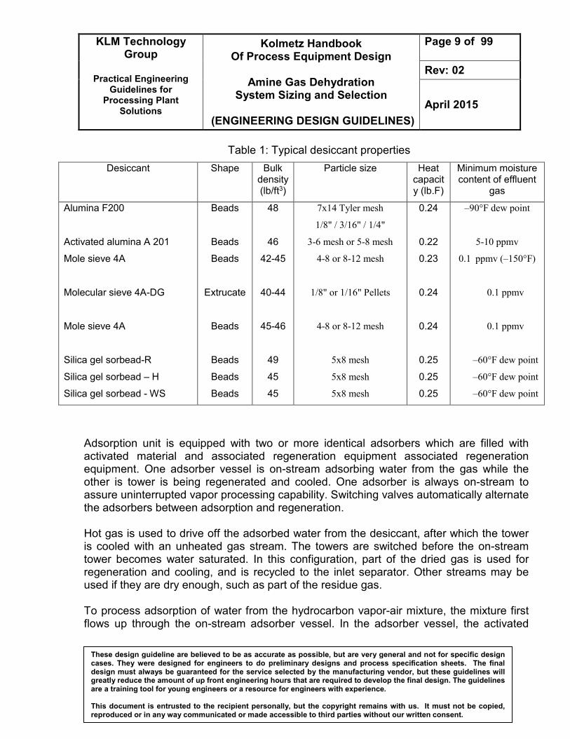
Table 1: Typical desiccant properties
Desiccant Shape Bulk density (lb/ft3)
Particle size Heat capacity (lb.F)
Minimum moisture content of effluent
gas
Alumina F200
Activated alumina A 201
Mole sieve 4A
Molecular sieve 4A-DG
Mole sieve 4A
Silica gel sorbead-R
Silica gel sorbead – H
Silica gel sorbead - WS
Beads
Beads
Beads
Extrucate
Beads
Beads
Beads
Beads
48
46
42-45
40-44
45-46
49
45
45
7x14 Tyler mesh
1/8" / 3/16" / 1/4"
3-6 mesh or 5-8 mesh
4-8 or 8-12 mesh
1/8" or 1/16" Pellets
4-8 or 8-12 mesh
5x8 mesh
5x8 mesh
5x8 mesh
0.24
0.22
0.23
0.24
0.24
0.25
0.25
0.25
–90°F dew point
5-10 ppmv
0.1 ppmv (–150°F)
0.1 ppmv
0.1 ppmv
–60°F dew point
–60°F dew point
–60°F dew point
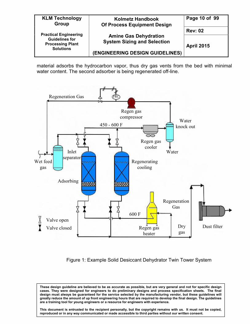
Adsorption unit is equipped with two or more identical adsorbers which are filled with activated material and associated regeneration equipment associated regeneration equipment. One adsorber vessel is on-stream adsorbing water from the gas while the other is tower is being regenerated and cooled. One adsorber is always on-stream to assure uninterrupted vapor processing capability. Switching valves automatically alternate the adsorbers between adsorption and regeneration. Hot gas is used to drive off the adsorbed water from the desiccant, after which the tower is cooled with an unheated gas stream. The towers are switched before the on-stream tower becomes water saturated. In this configuration, part of the dried gas is used for regeneration and cooling, and is recycled to the inlet separator. Other streams may be used if they are dry enough, such as part of the residue gas. To process adsorption of water from the hydrocarbon vapor-air mixture, the mixture first flows up through the on-stream adsorber vessel. In the adsorber vessel, the activated
KLM Technology Group
Practical Engineering
Guidelines for Processing Plant
Solutions
Kolmetz Handbook Of Process Equipment Design
Amine Gas Dehydration
System Sizing and Selection
(ENGINEERING DESIGN GUIDELINES)
Page 10 of 99
Rev: 02
April 2015
These design guideline are believed to be as accurate as possible, but are very general and not for specific design cases. They were designed for engineers to do preliminary designs and process specification sheets. The final design must always be guaranteed for the service selected by the manufacturing vendor, but these guidelines will greatly reduce the amount of up front engineering hours that are required to develop the final design. The guidelines are a training tool for young engineers or a resource for engineers with experience. This document is entrusted to the recipient personally, but the copyright remains with us. It must not be copied, reproduced or in any way communicated or made accessible to third parties without our written consent.
material adsorbs the hydrocarbon vapor, thus dry gas vents from the bed with minimal water content. The second adsorber is being regenerated off-line.
Figure 1: Example Solid Desiccant Dehydrator Twin Tower System
Regeneration Gas
Wet feed
gas
Inlet
separator
Adsorbing
Regenerating
cooling
Regen gas
cooler Water
Water
knock out
Regen gas
compressor
Regen gas
heater
Dust filter Dry
gas
Regeneration
Gas
Valve open
Valve closed
FRC
600 F
450 - 600 F
KLM Technology Group
Practical Engineering
Guidelines for Processing Plant
Solutions
Kolmetz Handbook Of Process Equipment Design
Amine Gas Dehydration
System Sizing and Selection
(ENGINEERING DESIGN GUIDELINES)
Page 11 of 99
Rev: 02
April 2015
These design guideline are believed to be as accurate as possible, but are very general and not for specific design cases. They were designed for engineers to do preliminary designs and process specification sheets. The final design must always be guaranteed for the service selected by the manufacturing vendor, but these guidelines will greatly reduce the amount of up front engineering hours that are required to develop the final design. The guidelines are a training tool for young engineers or a resource for engineers with experience. This document is entrusted to the recipient personally, but the copyright remains with us. It must not be copied, reproduced or in any way communicated or made accessible to third parties without our written consent.
During the adsorption period, the bed can be thought of as operating with three zones. The top zone is called the saturation or equilibrium zone. The desiccant in this zone is in equilibrium with the wet inlet gas. The middle or mass transfer zone (MTZ) is where the water content of the gas is reduced from its inlet concentration to < 1 ppm. The bottom zone is unused desiccant and is often called the active zone. If the bed operates too long in adsorption, the mass transfer zone begins to move out the bottom of the bed causing a “breakthrough.” At breakthrough, the water content of the outlet gas begins to increase and will eventually reach feed gas water content when the MTZ is completely displaced. Some matters should be considered while using adsorption method.
1. The continuous process requires two (or more) vessels with one on-line removing water while the other is being regenerated.
2. Generally a bed is designed to be on-line in adsorption for 8 to 24 hours. When the bed is taken off-line, the water is removed by heating to 375°F-600°F
3. The regeneration gas used to heat the bed is usually a slipstream of dry process gas.
4. Any heat source can be used including waste heat from engines and turbines.
5. Gas flow during adsorption is typically downflow. This allows higher gas velocities (thus smaller diameter towers) since bed fluidization is avoided.
6. Regeneration gas flow is upflow during the heating period. In this way, any residual water left on the desiccant will be at the top of the bed and will not affect the effluent dewpoint when adsorption is resumed. Upflow heating helps to strip any contaminants from the top of the bed extending desiccant life.
7. Regeneration gas flow during the cooling period may be upflow if the gas is completely free of water, which saves two switching valves per tower.
8. If the cooling gas contains water, cooling flow should be downflow to avoid preloading of the desiccant at the bottom of the bed with water.
9. The design pressure drop through the bed should be about 5 – 8 psi. A design pressure drop higher than 8 psi is not recommended as the desiccant is fragile and can be crushed by the total bed weight and pressure drop forces.
10. In the saturation zone, molecular sieve is expected to hold approximately 13 pounds of water per 100 pounds of sieve.
KLM Technology Group
Practical Engineering
Guidelines for Processing Plant
Solutions
Kolmetz Handbook Of Process Equipment Design
Amine Gas Dehydration
System Sizing and Selection
(ENGINEERING DESIGN GUIDELINES)
Page 12 of 99
Rev: 02
April 2015
These design guideline are believed to be as accurate as possible, but are very general and not for specific design cases. They were designed for engineers to do preliminary designs and process specification sheets. The final design must always be guaranteed for the service selected by the manufacturing vendor, but these guidelines will greatly reduce the amount of up front engineering hours that are required to develop the final design. The guidelines are a training tool for young engineers or a resource for engineers with experience. This document is entrusted to the recipient personally, but the copyright remains with us. It must not be copied, reproduced or in any way communicated or made accessible to third parties without our written consent.
11. The total bed height is the summation of the saturation zone and the mass transfer zone heights. It should be no less than the vessel inside diameter, or 6 feet whichever is greater.
Solid desiccant towers are insulated externally or possibly internally. Internal refractory requires careful installation and curing, usually before the desiccant is installed. It saves energy but the greatest benefit is it can dramatically reduce the required heating and cooling times. This is often an important benefit for systems where regeneration times are limited. The primary disadvantage is the potential for wet gas bypassing the desiccant through cracks and defects in the insulation during the adsorption cycle.
Absorption
Absorption dehydration involves the use of a liquid desiccant to remove water vapor from the gas. The most frequently used desiccants in absorption processes are di-ethylene and tri-ethylene glycols. Usually, the absorption/stripping cycle is used for removing large amounts of water, and adsorption is used for cryogenic systems to reach low moisture contents. Although many liquids possess the ability to absorb water from gas, the liquid that is most desirable to use for commercial dehydration purposes should possess the following properties:
1. High absorption efficiency.
2. Easy and economic regeneration.
3. Non-corrosive and non-toxic.
4. No operational problems when used in high concentrations.
5. No interaction with the hydrocarbon portion of the gas, and no contamination by acid gases.
The glycols, particularly ethylene glycol (EG), di-ethylene glycol (DEG), tri-ethylene glycol (TEG), and tetra-ethylene glycol (TREG) come to closest to satisfying these criteria to varying degrees. Water and the glycols show complete mutual solubility in the liquid phase due to hydrogen-oxygen bonds, and their water vapor pressures are very low. 1. Tri-ethylene glycol (TEG) is the most commonly used dehydration liquid and is the
assumed glycol type in this process description.
KLM Technology Group
Practical Engineering
Guidelines for Processing Plant
Solutions
Kolmetz Handbook Of Process Equipment Design
Amine Gas Dehydration
System Sizing and Selection
(ENGINEERING DESIGN GUIDELINES)
Page 13 of 99
Rev: 02
April 2015
These design guideline are believed to be as accurate as possible, but are very general and not for specific design cases. They were designed for engineers to do preliminary designs and process specification sheets. The final design must always be guaranteed for the service selected by the manufacturing vendor, but these guidelines will greatly reduce the amount of up front engineering hours that are required to develop the final design. The guidelines are a training tool for young engineers or a resource for engineers with experience. This document is entrusted to the recipient personally, but the copyright remains with us. It must not be copied, reproduced or in any way communicated or made accessible to third parties without our written consent.
2. Di-ethylene glycol (DEG) is sometimes used for dehydration for uniformity when hydrate inhibition is required upstream of dehydration.
3. Tetra-ethylene glycol (TREG) is more viscous and more expensive than the other glycols. The only real advantage is its lower vapor pressure which reduces absorber vapor loss. It should only be considered for rare cases where glycol dehydration will be employed on a gas whose temperature exceeds about 50 °C, such as when extreme ambient conditions prevent cooling to a lower temperature.
Care should be taken in using TEG downstream of production facilities that use MEG or DEG as a hydrate inhibitor, as any DEG or MEG carried over into the TEG system will degrade at the high temperatures encountered in the TEG regenerator.
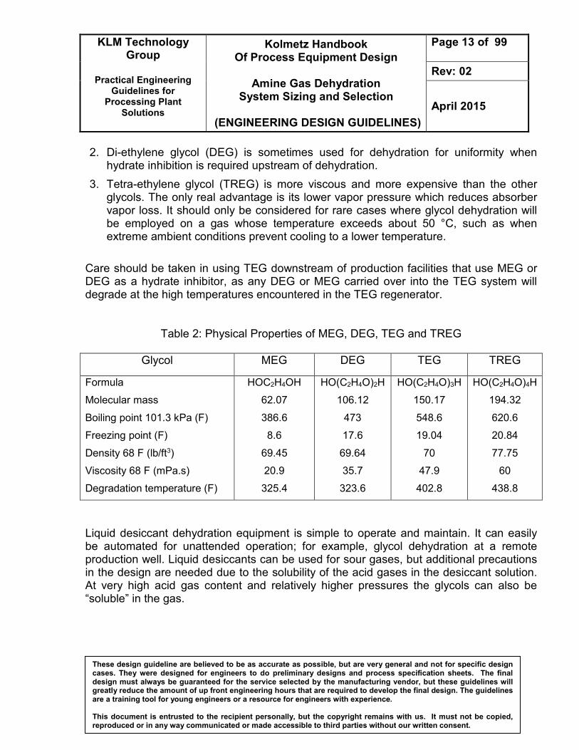
Table 2: Physical Properties of MEG, DEG, TEG and TREG
Glycol MEG DEG TEG TREG
Formula
Molecular mass
Boiling point 101.3 kPa (F)
Freezing point (F)
Density 68 F (lb/ft3)
Viscosity 68 F (mPa.s)
Degradation temperature (F)
HOC2H4OH
62.07
386.6
8.6
69.45
20.9
325.4
HO(C2H4O)2H
106.12
473
17.6
69.64
35.7
323.6
HO(C2H4O)3H
150.17
548.6
19.04
70
47.9
402.8
HO(C2H4O)4H
194.32
620.6
20.84
77.75
60
438.8
Liquid desiccant dehydration equipment is simple to operate and maintain. It can easily be automated for unattended operation; for example, glycol dehydration at a remote production well. Liquid desiccants can be used for sour gases, but additional precautions in the design are needed due to the solubility of the acid gases in the desiccant solution. At very high acid gas content and relatively higher pressures the glycols can also be “soluble” in the gas.
KLM Technology Group
Practical Engineering
Guidelines for Processing Plant
Solutions
Kolmetz Handbook Of Process Equipment Design
Amine Gas Dehydration
System Sizing and Selection
(ENGINEERING DESIGN GUIDELINES)
Page 14 of 99
Rev: 02
April 2015
These design guideline are believed to be as accurate as possible, but are very general and not for specific design cases. They were designed for engineers to do preliminary designs and process specification sheets. The final design must always be guaranteed for the service selected by the manufacturing vendor, but these guidelines will greatly reduce the amount of up front engineering hours that are required to develop the final design. The guidelines are a training tool for young engineers or a resource for engineers with experience. This document is entrusted to the recipient personally, but the copyright remains with us. It must not be copied, reproduced or in any way communicated or made accessible to third parties without our written consent.
For the process, the regenerated glycol is fed to the top of an absorber (contactor) where it is contacted with the wet natural gas stream The glycol absorbs water from the natural gas as it flows down through the contactor countercurrent by physical absorption to the gas flow. Water-rich glycol is removed from the bottom of the contactor while the dry natural gas leaves the top of the absorption column and is fed either to a pipeline system or to a gas plant. After leaving the absorber, the water-rich glycol is passes through the reflux condenser coil, flashes off most of the soluble gas in the flash tank (vessel) where hydrocarbon vapors are removed and any liquid hydrocarbons are skimmed from the glycol. This step is necessary as the absorber is typically operated at high pressure and the pressure must be reduced before the regeneration step. Due to the composition of the rich glycol, a vapor phase will form when the pressure is lowered having a high hydrocarbon content. After leaving the flash vessel, the rich glycol is heated in a cross-exchanger and fed to the regenerator. The glycol regenerator consists of a column, an overhead condenser, and a reboiler. In the regenerator, absorbed water is distilled from the glycol at near atmospheric pressure by application of heat. The glycol is thermally regenerated to remove excess water and regain the high glycol purity. The hot lean glycol is cooled by cross-exchange with rich glycol entering the regenerator. It is then fed to a lean pump where its pressure is elevated to that of the glycol absorber. After raising the pressure, the lean solvent is cooled again with a trim cooler before being recirculated into the absorber. This trim cooler can either be a cross-exchanger with the dry gas leaving the absorber. However, there are several operating problems with glycol dehydrators. Suspended foreign matter, such as dirt, scale and iron oxide, may contaminate glycol solutions. Also, overheating of the solutions may produce both low and high boiling decomposition products. The resultant sludge may collect on heating surfaces, causing some loss in efficiency or, in severe cases, complete flow stoppage. Liquids in inlet gas may require installation of an efficient separator ahead of the absorber. Foaming of solution may occur with resultant carry-over of liquid
KLM Technology Group
Practical Engineering
Guidelines for Processing Plant
Solutions
Kolmetz Handbook Of Process Equipment Design
Amine Gas Dehydration
System Sizing and Selection
(ENGINEERING DESIGN GUIDELINES)
Page 15 of 99
Rev: 02
April 2015
These design guideline are believed to be as accurate as possible, but are very general and not for specific design cases. They were designed for engineers to do preliminary designs and process specification sheets. The final design must always be guaranteed for the service selected by the manufacturing vendor, but these guidelines will greatly reduce the amount of up front engineering hours that are required to develop the final design. The guidelines are a training tool for young engineers or a resource for engineers with experience. This document is entrusted to the recipient personally, but the copyright remains with us. It must not be copied, reproduced or in any way communicated or made accessible to third parties without our written consent.
The design of glycol dehydration systems is developed as the project progresses from concept selection, through project specification and detailed design. It is important not to leave decisions to too late a point in the design development. The design shall be consistent with the rest of the plant’s design, for instance: 1. It shall encompass all the anticipated operating conditions and operating scenarios,
including start up from cold. 2. Its sparing, availability, start-up times etc shall be as per the requirements of the
project’s operating and maintenance philosophy and the project’s reliability, availability, maintainability study.
3. Its materials of construction shall be determined by the project’s material selection study.
4. The controls and shutdown functions shall be consistent with those of the rest of the project and subject to the same process controllability reviews, Hazops, IPFs.
5. Its environmental impact shall be assessed, justified and included in the project’s overall environmental impact.
KLM Technology Group
Practical Engineering
Guidelines for Processing Plant
Solutions
Kolmetz Handbook Of Process Equipment Design
Amine Gas Dehydration
System Sizing and Selection
(ENGINEERING DESIGN GUIDELINES)
Page 16 of 99
Rev: 02
April 2015
These design guideline are believed to be as accurate as possible, but are very general and not for specific design cases. They were designed for engineers to do preliminary designs and process specification sheets. The final design must always be guaranteed for the service selected by the manufacturing vendor, but these guidelines will greatly reduce the amount of up front engineering hours that are required to develop the final design. The guidelines are a training tool for young engineers or a resource for engineers with experience. This document is entrusted to the recipient personally, but the copyright remains with us. It must not be copied, reproduced or in any way communicated or made accessible to third parties without our written consent.
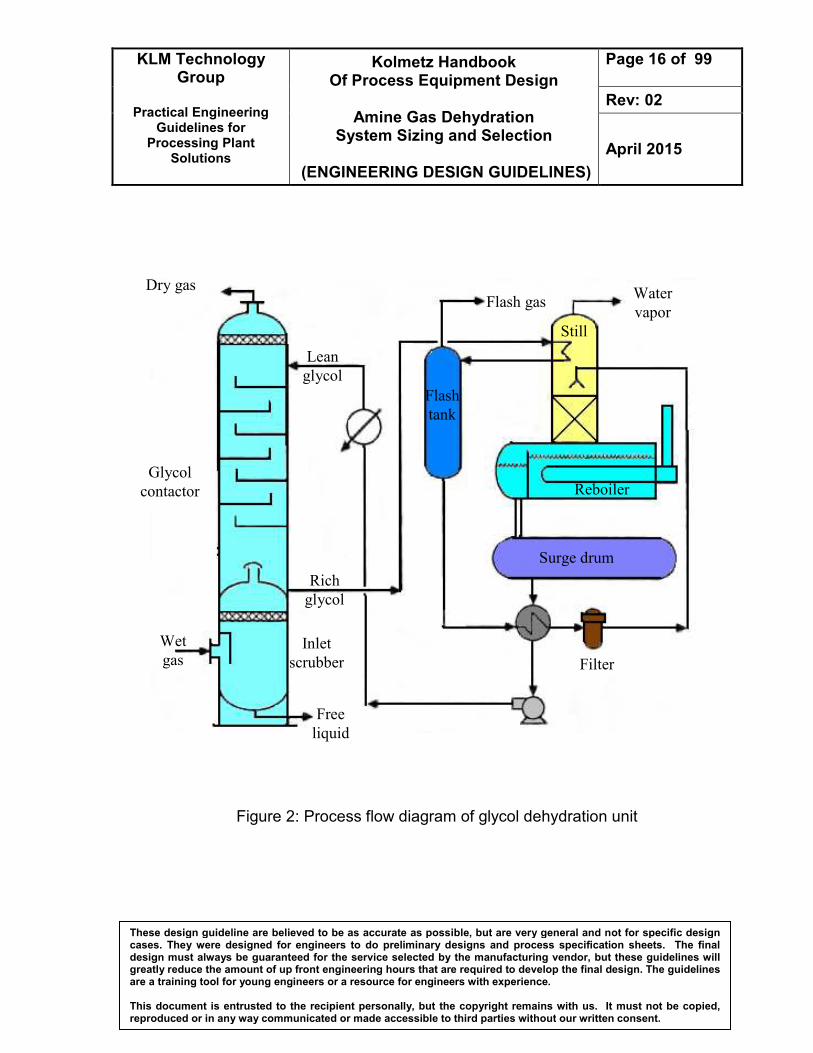
Figure 2: Process flow diagram of glycol dehydration unit
Dry gas
Glycol
contactor
Wet
gas
Free
liquid
Inlet
scrubber
Rich
glycol
Lean
glycol
Surge drum
Filter
Reboiler
Water
vapor Flash gas
Still
Flash
tank
KLM Technology Group
Practical Engineering
Guidelines for Processing Plant
Solutions
Kolmetz Handbook Of Process Equipment Design
Amine Gas Dehydration
System Sizing and Selection
(ENGINEERING DESIGN GUIDELINES)
Page 17 of 99
Rev: 02
April 2015
These design guideline are believed to be as accurate as possible, but are very general and not for specific design cases. They were designed for engineers to do preliminary designs and process specification sheets. The final design must always be guaranteed for the service selected by the manufacturing vendor, but these guidelines will greatly reduce the amount of up front engineering hours that are required to develop the final design. The guidelines are a training tool for young engineers or a resource for engineers with experience. This document is entrusted to the recipient personally, but the copyright remains with us. It must not be copied, reproduced or in any way communicated or made accessible to third parties without our written consent.
The overall design of a glycol system requires components optimization that interacts with each other and also allow for anticipated variations in operating conditions over the life of the plant. The optimization include of glycol circulation rate, dewpoint, temperature pressure, etc. In general, the total circulation rate is determined by the amount of water removal required. The water dewpoint depression, expressed as inlet dewpoint minus outlet dewpoint, is dependent on glycol circulation rate (in gall TEG/lb of water removed), the lean glycol concentration, the number of trays or depth of packing in the contactor and the contact temperature. Glycol dehydration system design is governed by the total glycol circulation capacity and the process variables discussed below Lean glycol concentration
The factors affecting concentration are the reboiler operating temperature and the quantity of stripping gas used. Increasing the lean glycol concentration alleviates the equilibrium limitation. The lean glycol concentration has the greatest effect on the dewpoint depression
Inlet gas temperature
Inlet gas temperature is a significant variable. Higher gas temperatures require more glycol circulation and also reduce the gas density leading to a higher volumetric gas flow and load factor. 15 °C is considered to be the minimum operating temperature for bubble cap trays due to the high viscosity of glycol at lower temperatures. For structured packing is desirable to have the inlet gas temperature at least 5 °C above the hydrate formation temperature. Gas cooling upstream of the inlet scrubber is generally recommended, especially for temperatures above 50 °C, About 60 °C is the upper practical temperature limit for glycol dehydration because of high glycol vaporization losses.
Pressure
Operation is theoretically possible up to pressures of 15 to 20 MPa. However, in practice operations at pressures above 13.5 MPa, would be unlikely. At pressures below about 3.5 MPa, the gas contains significantly more water vapor
KLM Technology Group
Practical Engineering
Guidelines for Processing Plant
Solutions
Kolmetz Handbook Of Process Equipment Design
Amine Gas Dehydration
System Sizing and Selection
(ENGINEERING DESIGN GUIDELINES)
Page 18 of 99
Rev: 02
April 2015
These design guideline are believed to be as accurate as possible, but are very general and not for specific design cases. They were designed for engineers to do preliminary designs and process specification sheets. The final design must always be guaranteed for the service selected by the manufacturing vendor, but these guidelines will greatly reduce the amount of up front engineering hours that are required to develop the final design. The guidelines are a training tool for young engineers or a resource for engineers with experience. This document is entrusted to the recipient personally, but the copyright remains with us. It must not be copied, reproduced or in any way communicated or made accessible to third parties without our written consent.
Circulation rate
The design circulation rate should be selected for a gas inlet temperature that will not be exceeded for more than 5 % of the time under any ambient or process conditions. Increasing the circulation rate will increase the dewpoint depression by providing a higher mean difference between the operating and equilibrium lines. A lower circulation rate will also reduce the sensible heat requirement of the system
Methods of increasing dewpoint depression
For a given number of trays, e.g. on an existing unit, a higher dewpoint depression can be achieved by increasing the circulation rate and/or increasing the lean glycol concentration.
KLM Technology Group
Practical Engineering
Guidelines for Processing Plant
Solutions
Kolmetz Handbook Of Process Equipment Design
Amine Gas Dehydration
System Sizing and Selection
(ENGINEERING DESIGN GUIDELINES)
Page 19 of 99
Rev: 02
April 2015
These design guideline are believed to be as accurate as possible, but are very general and not for specific design cases. They were designed for engineers to do preliminary designs and process specification sheets. The final design must always be guaranteed for the service selected by the manufacturing vendor, but these guidelines will greatly reduce the amount of up front engineering hours that are required to develop the final design. The guidelines are a training tool for young engineers or a resource for engineers with experience. This document is entrusted to the recipient personally, but the copyright remains with us. It must not be copied, reproduced or in any way communicated or made accessible to third parties without our written consent.
DEFINITIONS Absorption - A separation process involving the transfer of a substance from a gaseous phase to liquid phase through the phase boundary. Absorber (Contactor) - A vertical pressure vessel where gas and glycol are intermingled counter-currently to remove water vapor from the gas. The contactor usually contains bubble cap trays, valve trays or structured packing. Absorption process - The attraction and retention of vapors (water) by liquids (glycol) from a gas stream. Actual trays - The number of trays installed in a column or the equivalent number of actual trays for a packed column. Bubble cap tray - Horizontal plate holding bubble caps and downcomers in the contactor. Bubble caps - Slotted metal caps attached over elevated nozzles (risers) on the bubble cap trays. The slots cause the gas to break up into small bubbles for intimate contact with the glycol. Claus Process – Catalytic chemical process that is used for converting gaseous hydrogen sulfide (H2S) into elemental sulfur (S). Commonly referred to as sulfur recovery unit (SRU) and is very widely used to produce sulfur from the hydrogen sulfide found in raw natural gas and from the by-product sour gases containing hydrogen sulfide derived from refining petroleum crude oil and other industrial facilities. Condensate - Light hydrocarbon liquids. Dehydration - Removal of water vapor from a gas. Desiccant - An adsorbent that shows primary selectivity for the removal of water Desiccant Fouling Material adsorbed from the carrier stream may not be desorbed satisfactorily on regeneration. Some reaction may also occur on the adsorbent leading to products that are not desorbed. These reaction products may inhibit efficient adsorption and obstruct or "foul" capacity of the active surface.
KLM Technology Group
Practical Engineering
Guidelines for Processing Plant
Solutions
Kolmetz Handbook Of Process Equipment Design
Amine Gas Dehydration
System Sizing and Selection
(ENGINEERING DESIGN GUIDELINES)
Page 20 of 99
Rev: 02
April 2015
These design guideline are believed to be as accurate as possible, but are very general and not for specific design cases. They were designed for engineers to do preliminary designs and process specification sheets. The final design must always be guaranteed for the service selected by the manufacturing vendor, but these guidelines will greatly reduce the amount of up front engineering hours that are required to develop the final design. The guidelines are a training tool for young engineers or a resource for engineers with experience. This document is entrusted to the recipient personally, but the copyright remains with us. It must not be copied, reproduced or in any way communicated or made accessible to third parties without our written consent.
Design pressure - The pressure used in the design of a vessel for the purpose of determining the minimum permissible wall thickness or physical characteristics of the different parts of the vessel. Dewpoint - The temperature at which vapor begins to condense into a liquid at a particular system pressure. A natural gas stream exhibits both hydrocarbon and water dewpoints. Sometimes the dewpoint is only a meta-stable condition – in the stable condition the condensed material is a solid (ice/hydrate) occurring at a higher temperature. Dewpoint depression - The difference in water dewpoint temperature between the gas entering and leaving the contactor. Downcomer - The vertical conduit between trays which allows liquid to pass from tray to tray. Flooding - The condition wherein excess liquid hold-up occurs and normal counter flow action is prevented in the glycol contactor, regeneration still or stripping column. It is a design limit which when reached in operation causes an excessive loss of liquid from the top of the column. Foaming - the continuous formation of bubbles which have sufficiently high surface tension to remain as bubbles beyond the disengaging surface. Fouling - the accumulation of unwanted material on solid surfaces to the detriment of function Free water - Liquid water which is not dissolved in any other substance. Gas/glycol heat exchanger - A heat exchanger employed to cool the lean glycol by the gas leaving the contactor before the glycol enters the contactor Glycol - A hygroscopic liquid. Mono-ethylene Glycol (MEG) and Di-ethylene Glycol (DEG) are commonly used in hydrate inhibition service and Tri-ethylene Glycol (TEG) is most common in gas dehydration service.
KLM Technology Group
Practical Engineering
Guidelines for Processing Plant
Solutions
Kolmetz Handbook Of Process Equipment Design
Amine Gas Dehydration
System Sizing and Selection
(ENGINEERING DESIGN GUIDELINES)
Page 21 of 99
Rev: 02
April 2015
These design guideline are believed to be as accurate as possible, but are very general and not for specific design cases. They were designed for engineers to do preliminary designs and process specification sheets. The final design must always be guaranteed for the service selected by the manufacturing vendor, but these guidelines will greatly reduce the amount of up front engineering hours that are required to develop the final design. The guidelines are a training tool for young engineers or a resource for engineers with experience. This document is entrusted to the recipient personally, but the copyright remains with us. It must not be copied, reproduced or in any way communicated or made accessible to third parties without our written consent.
Lean glycol (or Dry glycol) - Glycol which has been regenerated and has a low water content. Rich glycol (or Wet glycol) - Glycol which has absorbed water and thus has a high water content. Glycol flash separator - A two or three phase separator which is used in the rich glycol stream to remove entrained gas and hydrocarbon liquids. Glycol/glycol exchanger - A heat exchanger employed to recover heat from the outgoing hot lean glycol from the reboiler and for preheating the incoming cool rich glycol from the contactor. Heat duty - The rate of heat absorption by the process. Heat flux - The average heat transfer rate through the heat exchanger tube, to the fluid. Height of a transfer unit (HTU) - The height of packing required to give one mass transfer unit. Hydrate - A clathrate compound formed by a combination of methane, ethane, propane, iso-butane, H2S or CO2 and water at elevated pressure and low temperature. Inlet gas separator (Scrubber) - A separator which removes free liquids from the inlet gas stream. The separator may be separate from or integral with the contactor. Liquid seal - A liquid column in the downcomer that forces the gas to pass up through the trays rather than up the downcomer. Packing - Material installed in the contactor, still column or stripping column that provides a large surface area for intermingling liquid and vapor to facilitate mass transfer during absorption, distillation or stripping. Random packing consists of shaped pieces (e.g. rings, saddles) that have been dumped, not stacked, in the column. Structured packing is essentially a series of parallel formed metal sheets. pH - Measure of the acidity of a liquid on a scale of 0 to 14 with 7 being neutral. 0 to 7 is acidic and 7 to 14 is alkaline.
KLM Technology Group
Practical Engineering
Guidelines for Processing Plant
Solutions
Kolmetz Handbook Of Process Equipment Design
Amine Gas Dehydration
System Sizing and Selection
(ENGINEERING DESIGN GUIDELINES)
Page 22 of 99
Rev: 02
April 2015
These design guideline are believed to be as accurate as possible, but are very general and not for specific design cases. They were designed for engineers to do preliminary designs and process specification sheets. The final design must always be guaranteed for the service selected by the manufacturing vendor, but these guidelines will greatly reduce the amount of up front engineering hours that are required to develop the final design. The guidelines are a training tool for young engineers or a resource for engineers with experience. This document is entrusted to the recipient personally, but the copyright remains with us. It must not be copied, reproduced or in any way communicated or made accessible to third parties without our written consent.
Reboiler - A vessel for boiling water out of the glycol. Regenerator - A unit including reboiler, still column and other related facilities to regenerate (or re-concentrate) rich glycol to lean glycol. Reflux - Condensed liquid which flows back down a column to maximize separation efficiency. Saturated gas (with respect to water) - A gas stream which contains the maximum amount of water vapor at a given temperature and pressure without condensing the water. Sparging tube - Internal pipe in the reboiler used to distribute stripping gas. Standard (pressure and temperature) - Unit of ideal gas volume at reference conditions of 101.325 kPa and 15 °C. Abbreviated: m3(st). Still reflux column - Vertically mounted distillation (fractionation) column on top of the reboiler. Stripping column - A packed column where glycol from the reboiler flows downward to the surge drum while gas flows upward stripping the glycol of water. Stripping gas - Gas that is contacted with glycol to help remove water from the glycol. Surge drum - Reservoir for regenerated glycol which may be integral with, or separate from, the reboiler. Sweet service - Where the partial pressure of H2S is less than 0.34 kPa. Cyclone tube - A high capacity cyclone type contacting device. A number of tubes may be assembled on a deck or tray for gas/liquid separation (de-misting) or glycol contacting. Theoretical tray - One in which the vapor and liquid leaving the stage are in equilibrium. The number of actual trays is equal to the number of theoretical trays divided by the overall tray efficiency.
KLM Technology Group
Practical Engineering
Guidelines for Processing Plant
Solutions
Kolmetz Handbook Of Process Equipment Design
Amine Gas Dehydration
System Sizing and Selection
(ENGINEERING DESIGN GUIDELINES)
Page 23 of 99
Rev: 02
April 2015
These design guideline are believed to be as accurate as possible, but are very general and not for specific design cases. They were designed for engineers to do preliminary designs and process specification sheets. The final design must always be guaranteed for the service selected by the manufacturing vendor, but these guidelines will greatly reduce the amount of up front engineering hours that are required to develop the final design. The guidelines are a training tool for young engineers or a resource for engineers with experience. This document is entrusted to the recipient personally, but the copyright remains with us. It must not be copied, reproduced or in any way communicated or made accessible to third parties without our written consent.
Transfer unit - The dimensionless distance within which every solute molecule has "unit opportunity" to transfer to the gas phase. A transfer unit can be calculated for a theoretical stage. Tray efficiency - The ratio between the number of theoretical and actual trays. Unit circulation rate (UCR) - Volumetric or mass flowrate of lean glycol per mass flowrate of water removed Valve tray - Horizontal plate holding valves and downcomers in the contactor. A valve consists of a liftable metal plate which covers a hole in the tray, providing a variable area for gas flow. NOMENCLATURE AC Cross sectional area of scrubber, ft2 ACP Cross sectional area of packing, ft2 AS Specific area of packing, ft²/ft³ ASC Cross sectional area of scrubber. ft2 DC Column diameter, ft DG The required diameter of packing generator, ft DSC The diameter of scrubber, ft Gac Contactor allowable gas flow rate, MMSCFD/ft2 GAC Allowable gas flow rate in contactor, MMSCFD/ft2 Gas Scrubber allowable gas flow rate, MMSCFD/ft2 GASC Allowable gas flow rate in scrubber, MMSCFD/ft2 GG Allowable flow rate per unit area, lb/s ft2
GS Gas flow rate, MMSCFD GH2S Feed H2S, MMSCFD GCO2 Feed CO2, MMSCFD GH2O Feed H2O, MMSCFD gspc Gas specific grafity Η Packing height, ft HTU Height of transfer unit of packing, ft L Glycol circulation rate, gal/hr
LW Glycol to water circulation rate, gall/lb water mg Gas mass flow rate, lb/s
KLM Technology Group
Practical Engineering
Guidelines for Processing Plant
Solutions
Kolmetz Handbook Of Process Equipment Design
Amine Gas Dehydration
System Sizing and Selection
(ENGINEERING DESIGN GUIDELINES)
Page 24 of 99
Rev: 02
April 2015
These design guideline are believed to be as accurate as possible, but are very general and not for specific design cases. They were designed for engineers to do preliminary designs and process specification sheets. The final design must always be guaranteed for the service selected by the manufacturing vendor, but these guidelines will greatly reduce the amount of up front engineering hours that are required to develop the final design. The guidelines are a training tool for young engineers or a resource for engineers with experience. This document is entrusted to the recipient personally, but the copyright remains with us. It must not be copied, reproduced or in any way communicated or made accessible to third parties without our written consent.
NTU Number transfer unit Pop Operating pressure, MMSCFD PT Total Pressure, Psia PH2S Pressure H2S, Psia PCO2 Pressure CO2, Psia PH2O Pressure H2O, Psia PDsprod Pressure dry sweet product Qmax Volumetric flow rate, MMSCFD QR Reboiler duty, btu/hr t Liquid retention time, min TDP Dew point temperature, F Tin Gas inlet temperature, F V Flash separator, gallon Vst Minimum liquid rates, ft/s Win Water content in inlet gas, lb/MMSCF Wout Water content in outlet gas, lb/MMSCF Wr Water removal, lb/hr %glyc Lean glycol concentration, %wt Greek Letters λmax Load factor, ft/s ρg Density of gas, lb/ft3 ρglyc Density of glycol, lb/ft3
Superscript A Area, ft2 G Flow rate, MMSCFD/ft2 Η Packing height, ft HTU Height of transfer unit of packing, ft NTU Number transfer unit T Temperature, F