
Jackson Heart Study Protocol · 18/02/2001 · Major differences in blood pressure measurement...
77
Jackson Heart Study Protocol Manual 4 Blood Pressure Visit 1 Version 1.0 February 18, 2001 For Copies, Please Contact: Jackson Heart Study Coordinating Center Jackson Medical Mall 350 W. Woodrow Wilson Dr. Jackson, MS 39213 M4-Version1.0_02-18-2001(1)
Transcript of Jackson Heart Study Protocol · 18/02/2001 · Major differences in blood pressure measurement...

Jackson Heart Study Protocol
Manual 4
Blood Pressure
Visit 1
Version 1.0
February 18, 2001
For Copies, Please Contact:
Jackson Heart Study Coordinating Center Jackson Medical Mall
350 W. Woodrow Wilson Dr. Jackson, MS 39213
M4-Version1.0_02-18-2001(1)


i
FOREWORD This manual is one of a series of protocols and manuals of operation for the Jackson Heart Study (JHS). The complexity of the JHS requires that a sizeable number of procedures be described, thus this rather extensive list of materials has been organized into the set of manuals listed below. Manual 1 provides the background, organization, and general objectives of the JHS Study. Manuals 2 and 10 describe the operation of the Cohort and Surveillance Components of the study. Detailed Manuals of Operation for specific procedures, including those of reading centers and central laboratories, make up Manuals 3 through 9 and 11.
JHS Study Protocols and Manuals of Operation
MANUAL TITLE
1 General Description and Study Management
2 Cohort Component Procedures
3 Family Study
4 Blood Pressure
5 Electrocardiography
6 Echocardiography
7 Ultrasound Assessment
8 Pulmonary Function Assessment
9 Specimen Collection and Processing
10 Morbidity and Mortality Classification Manual
11 Data Management System
M4-Version1.0_02-18-2001(1)


iii
Manual 4. Blood Pressure
Table of Contents
1.0 SITTING BLOOD PRESSURE PROTOCOL ..............................................................................1
1.1 Introduction ..............................................................................................................................1
1.2 Standardized Clinic Procedures...............................................................................................1
1.3 Description of the Equipment...................................................................................................1
1.4 Blood Pressure Measurement Instructions ..............................................................................3
1.5 Staff Preparation for Participant Visit .......................................................................................3
1.6 Measurement Procedures........................................................................................................3
1.7 Procedure for Changing the Peak Inflation Level ....................................................................5
1.8 Reporting the Blood Pressure Results to the Participant.........................................................5
1.9 Stopping Rules for Elevated Blood Pressure...........................................................................5
1.10 Sitting Blood Pressure Training and Certification ....................................................................6
1.11 Quality Control .........................................................................................................................8
1.12 Technician Training and Quality Control..................................................................................8
1.13 Equipment Maintenance ..........................................................................................................9
1.14 Referral of Hypertensives.........................................................................................................9
2.0 ANKLE/BRACHIAL SYSTOLIC BLOOD PRESSURE PROTOCOL.......................................10
2.1 Purpose..................................................................................................................................10
2.2 Equipment ..............................................................................................................................10
2.3 Exclusions ..............................................................................................................................10
2.4 Set-Up Procedure ..................................................................................................................11
2.5 Procedure...............................................................................................................................11
2.6 Tips for Ankle-Arm Measurements ........................................................................................14
2.7 Quality Assurance ..................................................................................................................17
3.0 AMBULATORY BLOOD PRESSURE MONITORING..............................................................18
3.1 Introduction and Equipment ...................................................................................................18
3.2 Operations Overview for Jackson Heart Study......................................................................28
3.3 Introduction to the Medicom ABPM Software ........................................................................32
3.4 Programming and Downloading the Monitor..........................................................................37
3.5 Participant Instructions...........................................................................................................49
3.6 Quality Control Grey Areas ....................................................................................................53
3.7 ABPM Step-by-Step Procedures ...........................................................................................54
M4-Version1.0_02-18-2001(1)

iv
APPENDICES
Appendix 1 Check Procedures and Maintenance Instructions Random-Zero Sphygmomanometer.................................................................................................A-1
Appendix 2 Maintenance for Standard Sphygmomanometer ......................................................A-3
Appendix 3 Checklist for Biannual Observation of BP Technicians.............................................A-4
Appendix 4 Monthly Log for Sitting BP Station ............................................................................A-6
Appendix 5 Accuracy Check on the Random-Zero Sphygmomanometer ...................................A-9
Appendix 6 Form for Recording Simultaneous BP Observation on a Volunteer by Two Technicians .............................................................................................................A-10
M4-Version1.0_02-18-2001(1)

v
Manual 4. Blood Pressure
Tables
Table 1. Determination Of Cuff Size Based On Arm Circumference .................................................3
Table 2. Classification Of Blood Pressure For Adults ........................................................................6
Table 3. Medical Care Referral Guidelines For Blood Pressure Based On Initial Measurements.....6
Table 4. Determination Of Cuff Size Based On Arm And Ankle Circumference..............................11
Table 5. Error Code Solution Table..................................................................................................51
Table 6. Grey Area Decision Table ..................................................................................................53
Figures
Figure 1. Changing The Peak Inflation Level On Paper Forms...........................................................5
Figure 2. Right And Left Ankle Cuff Placement .................................................................................13
Figure 3. Doppler Probe Position.......................................................................................................14
Figure 4. Calibration Setup ................................................................................................................19
Figure 5. Monitor Vs. Mercury Column Calibration Table .................................................................20
Figure 6. Dell Computer Data Key.....................................................................................................22
Figure 7. Dell Computer Diagram......................................................................................................22
Figure 8. IBM Data Key .....................................................................................................................23
Figure 9. Compaq Computer Diagram ..............................................................................................24
Figure 10. Compaq Data Key...........................................................................................................24
Figure 11. Spacelabs ABP Monitor ..................................................................................................25
Figure 12. Spacelabs ABP Monitor Front Panel ..............................................................................25
Figure 13. Spacelabs ABP Monitor Rear Panel...............................................................................26
M4-Version1.0_02-18-2001(1)

vi
Figure 14. ABPM Battery Positions ................................................................................................. 26
Figure 15. Bladder Insertion (1)....................................................................................................... 27
Figure 16. Bladder Insertion (2)....................................................................................................... 27
Figure 17. Medicom Main Menu ...................................................................................................... 33
Figure 18. Medicom Equipment Setup Menu .................................................................................. 33
Figure 19. Medicom Edit Data Menu ............................................................................................... 34
Figure 20. Medicom Display Data Menu ......................................................................................... 35
Figure 21. Medicom Exit Editor Menu ............................................................................................. 36
Figure 22. Medicom Program Monitor Screen................................................................................. 38
Figure 23. Edit Correlation Readings Prompt Box .......................................................................... 43
Figure 24. Edit Correlation Readings (Beginning Of Test) Prompt Box .......................................... 43
Figure 25. Edit Correlation Readings (Beginning Of Test) Prompt Box #2 ..................................... 43
Figure 26. Edit Correlation Readings Prompt Box .......................................................................... 44
Figure 27. Edit Correlation Readings (Conclusion Of Test) Prompt Box ........................................ 44
Figure 28. Edit Correlation Readings (Conclusion Of Test) Prompt Box #2 ................................... 44
Figure 29. Documentation Example For Jackson Heart.................................................................. 47
M4-Version1.0_02-18-2001(1)

1
1.0 SITTING BLOOD PRESSURE PROTOCOL 1.1 Introduction As blood pressure rises, so does risk of ischemic heart disease and its complications. The range of normal blood pressures is wide. Even within the "normal" range, risk increases as the upper limits are approached. Usually, blood pressures are expressed as systolic pressure/diastolic pressure; values exceeding 140/90 mmHg are considered to be hypertensive for adults. Classification and staging of hypertension are more precise where systolic rather than diastolic is the principle criterion. Both systolic and diastolic measuring blood pressure are associated with increasing risk for cardiovascular disease. Middle-aged persons with a diastolic blood pressure of 90-104 mmHg (so-called "mild" hypertension) have a risk of heart attack that is about 70 percent higher than that of persons with a diastolic pressure under 80 mmHg (optimal value). Persons with a diastolic blood pressure exceeding 104 mmHg (moderately severe to severe hypertension) have a risk more than twice that of those with a normal value. Hypertension is an especially strong risk factor for stroke and, to a lesser extent, for peripheral vascular disease. Most of the knowledge of the consequences of high blood pressure arises from studies of sitting arm blood pressure, as described in this section. Sitting blood pressure in the first exam (Visit 1) is measured in a resting state, using 2 measurements with a random zero sphygmomanometer. The random zero machine has two advantages over the fixed zero manometer. Digit preference does not appear in the data. It may still exist in the reading itself, but it is "removed" from the data by the use of the randomly chosen zero point. More importantly, it prevents the blood pressure technician from knowing the actual value, and therefore removes judgements about blood pressure levels for readings close to critical values such as 90 diastolic. It should be noted, however, that the random zero machines tend to yield blood pressures which are about 1.5 mmHg less than those obtained when using a fixed zero machine. Within person variation in blood pressure is substantial, even within a few minutes and particularly under conditions perceived as stressful. Use of two replicate readings tends to reduce this short-term variation. 1.2 Standardized Clinic Procedures Correct measurement of blood pressure is of the utmost importance to the success of this study. It is essential that the procedure described below for measuring blood pressure be followed exactly. Major differences in blood pressure measurement methodology among health professionals from several countries have been observed despite the fact that a joint committee of the American Heart Association and the Cardiac Society of Great Britain and Ireland established international recommendations on blood pressure measurement in 1939. Precision is essential for valid comparisons of blood pressure between groups of people and in individuals on different occasions. 1.3 Description of the Equipment 1.3.1 Stethoscope A standard Littman stethoscope with a bell is used. Korotkoff sounds, described as Phase 1 through Phase 5, are best heard with the bell because of their low pitch. Stethoscope tubing should be about 10-12 inches from the bell piece to "Y" branching. This length provides optimal acoustical properties and allows the observer to read the sphygmomanometer at eye level and in a comfortable position. Earpieces should fit comfortably and snugly in the ears. Four points should be observed in using the stethoscope.
1. The earpieces should be directed downwards and forwards into the external ear canal.
M4-Version1.0_02-18-2001(1)

2
2. The earpieces should be tight enough to exclude outside sound but not so tight that they cause discomfort.
3. The valve between the bell and the diaphragm should be turned in the correct direction.
4. The bell of the stethoscope should be placed lightly on the skin overlying the brachial artery -
immediately below the cuff and medial to the cubital fossa above the medial epicondyle of the radius and posterior to the biceps muscle. Light pressure accentuates low-pitched sound and avoids compression murmurs. Pressing too heavily with the stethoscope over the brachial artery causes turbulent flow in the artery and a murmur can be heard which may prolong the apparent duration of phase 4.
1.3.2 Sphygmomanometers Standardized Hawksley random-zero instruments are used for all clinic visits. Standard Baum manometers are used for determining peak inflation level. The mercury manometer consists of a screw cap, a face with numbers, a lined glass column, a reservoir containing mercury, rubber tubing, and a metal case. The rubber tubing from the mercury manometer connects to the rubber tubing from the inflatable rubber bladder of the cuff. As the inflatable rubber bladder is filled with air, the air pressure in the bladder travels through the connecting rubber tubing. The pressure pushes the mercury out of the reservoir and into the lined glass column. The number for each line is read when the rounded top of the mercury, the meniscus, is level with it. If the meniscus is exactly between the lines, the reading is made from the line immediately above, i.e., rounded up to the nearest even number. 1.3.3 Random-Zero Mercury Manometer The random-zero (R-Z) manometer has all the parts of the standard mercury manometer. In addition, it has a device built into the box-shaped back that changes the level of mercury in the calibrated glass tube. The device includes a second mercury reservoir the size of which can be changed to hold a larger or smaller amount of the mercury and therefore allow different amounts of mercury to remain in the calibrated glass tube and the outside reservoir. Turning a wheel on the side of the wooden box changes the size of the second reservoir. The second reservoir is opened and closed with a bellows control valve on the face of the manometer. 1.3.4 Cuffs and Bulbs Proper size of the cuff is essential for accurate blood pressure measurement. The Examination Center has four standardized cuffs available - small adult, adult, large adult, and thigh cuff. The standardized cuffs (provided are by the Baum Company) are used for the measurement of sitting blood pressure. The range markings on commercial cuffs overlap from size to size and do not offer a precise guideline. In the JHS Study arm size is measured, and the cuff size is selected as illustrated in Table 1, below.
M4-Version1.0_02-18-2001(1)
3
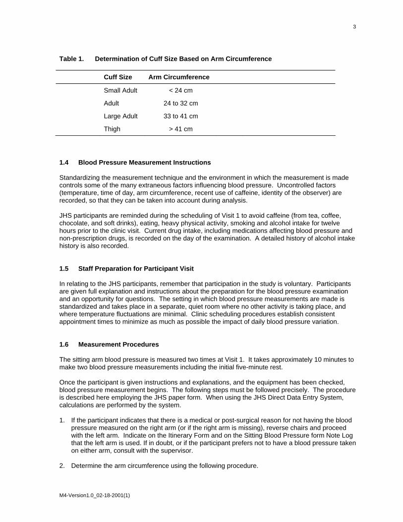
Table 1. Determination of Cuff Size Based on Arm Circumference Cuff Size Arm Circumference
Small Adult < 24 cm
Adult 24 to 32 cm
Large Adult 33 to 41 cm
Thigh > 41 cm 1.4 Blood Pressure Measurement Instructions Standardizing the measurement technique and the environment in which the measurement is made controls some of the many extraneous factors influencing blood pressure. Uncontrolled factors (temperature, time of day, arm circumference, recent use of caffeine, identity of the observer) are recorded, so that they can be taken into account during analysis. JHS participants are reminded during the scheduling of Visit 1 to avoid caffeine (from tea, coffee, chocolate, and soft drinks), eating, heavy physical activity, smoking and alcohol intake for twelve hours prior to the clinic visit. Current drug intake, including medications affecting blood pressure and non-prescription drugs, is recorded on the day of the examination. A detailed history of alcohol intake history is also recorded. 1.5 Staff Preparation for Participant Visit In relating to the JHS participants, remember that participation in the study is voluntary. Participants are given full explanation and instructions about the preparation for the blood pressure examination and an opportunity for questions. The setting in which blood pressure measurements are made is standardized and takes place in a separate, quiet room where no other activity is taking place, and where temperature fluctuations are minimal. Clinic scheduling procedures establish consistent appointment times to minimize as much as possible the impact of daily blood pressure variation. 1.6 Measurement Procedures The sitting arm blood pressure is measured two times at Visit 1. It takes approximately 10 minutes to make two blood pressure measurements including the initial five-minute rest. Once the participant is given instructions and explanations, and the equipment has been checked, blood pressure measurement begins. The following steps must be followed precisely. The procedure is described here employing the JHS paper form. When using the JHS Direct Data Entry System, calculations are performed by the system. 1. If the participant indicates that there is a medical or post-surgical reason for not having the blood
pressure measured on the right arm (or if the right arm is missing), reverse chairs and proceed with the left arm. Indicate on the Itinerary Form and on the Sitting Blood Pressure form Note Log that the left arm is used. If in doubt, or if the participant prefers not to have a blood pressure taken on either arm, consult with the supervisor.
2. Determine the arm circumference using the following procedure.
M4-Version1.0_02-18-2001(1)

4
The participant stands facing away from the observer with the right arm flexed at 90 degrees at the elbow, hand across midsection. The observer determines and marks the tip of the olecranon (elbow). The participant straightens the arm, allowing it to hang loosely at the side. The observer then determines and marks the posterior tip of the acromion process (shoulder bone). Using a centimeter tape, the observer measures the length of the upper arm between the two marks and marks the midpoint (+). The observer wraps the tape around the arm over the midpoint mark, making sure that the tape is level. The arm circumference is measured to the nearest centimeter, and is recorded.
3. Seat the participant with right arm on table. The bend at the elbow (cubital fossa) should be at
heart level. Legs should be uncrossed and feet comfortably flat on the floor, not dangling. Be sure that the chair head support is comfortable and the participant is able to relax the neck and shoulder muscles as much as possible.
4. Palpate the brachial artery (just medial to and above the cubital fossa), and mark this location for
stethoscope placement. Choose the correct cuff size and wrap the cuff on the arm with the center of the bladder over the artery. If the participant seems particularly apprehensive, delay wrapping the cuff until after the five-minute wait.
5. Record the time. Start five-minute timer. Allow a five-minute wait before taking the blood
pressure. Conversation should be limited. However, a brief explanation of the procedure can be repeated at this time if necessary. The smoking and fasting questions may be asked after timing is begun.
6. After the 5-minute rest, check and record the 30-second heart rate. Then, connect the cuff to a
standard manometer and establish the pulse obliteration pressure by slowly inflating while palpating the radial artery until pulse is no longer felt. Deflate and disconnect the cuff. Record the pulse obliteration pressure. Record the R-Z maximum zero number (found next to mercury column). Calculate and record the peak inflation level (i.e., pulse obliteration pressure + R-Z maximum zero number + 30).
7. Measurement 1: Connect the cuff to the random-zero manometer. Open the bellows control
valve and wait until the mercury settles. Using downstrokes only turn the thumbwheel two or three times. Note: Do not spin the thumbwheel. Place the bell of the stethoscope on the brachial artery. Inflate rapidly to the R-Z peak inflation level. Holding the pressure constant with the bulb, wait 5 seconds. Close the bellows control valve. Slowly deflate the cuff (2 mm per second) while listening. Record the 1st and 5th phases, reading the pressure in mmHg to the nearest even number. The first sound heard in a series of at least two sounds is recorded for systolic blood pressure (phase 1). The first silence in a series of at least two silences is recorded for diastolic blood pressure (phase 5), not the last sound heard. Disconnect the cuff and record the zero reading.
8. Measurement 2: Have the participant raise measurement arm for five seconds. After waiting
another 25 seconds with the participant's arm on the table, repeat the measurement as in step 7 above and disconnect cuff.
Blood pressure calculations are made for the first and second readings. When using paper forms, subtract the zero value from the readings to get the actual (corrected) systolic and diastolic blood pressure measurement. This is done on the worksheet at the end of the form. Because of the importance of the blood pressure averages, to inform the participant and for the purpose of referral, all arithmetic is done with a calculator.
M4-Version1.0_02-18-2001(1)

5
If for any reason the observer is unable to complete, or has forgotten to complete any portion of the exam (and the participant is gone), draw two horizontal lines through the space(s) on the form, if using paper forms. This is the correct way to indicate missed information. If an entire reading is missed and the participant is still sitting at the blood pressure workstation, completely deflate the cuff and start over with a replacement reading. However, under no other circumstances may a replacement reading be obtained. Always wait at least 30 seconds between readings. 1.7 Procedure for Changing the Peak Inflation Level Occasionally the Korotkoff sounds may be heard as soon as one places the stethoscope over the brachial pulse. If this happens, the peak inflation level used was too low. The observer immediately deflates the cuff by releasing the thumbscrew and disconnecting the cuff tube. Then have the participant hold the cuff-wrapped arm vertically for five seconds. As shown below in Table 2, draw a line through the previously recorded Pulse Obliteration Pressure and Peak Inflation Level. Increase each number by ten and write the new number above the original one, as shown below. When using the Direct Data Entry system, the Peak Inflation Level values change automatically when the Pulse Obliteration Pressure is changed. Proceed with blood pressure measurement, starting at the new Peak Inflation Level. Figure 1. Changing the Peak Inflation Level on paper forms. 130 Pulse obliteration pressure 120 R-Z maximum Zero + 22 + 30 =182 Peak Inflation Level 172 (Random-Zero) 1.8 Reporting the Blood Pressure Results to the Participant Using a calculator, average the first and second corrected R-Z readings and record the average on the form if using paper forms. Record this average on the transmittal slip or itinerary form in the participant's folder, and mention the results to the participant. State clearly the systolic and diastolic pressure, and indicate that the participant will receive a written report with these valves at the end of the visit. 1.9 Stopping Rules for Elevated Blood Pressure The classification of blood pressure for adults is summarized in Table 3. The medical care referral guidelines for elevated blood pressure are summarized in Table 4. When a person has one or more sitting blood pressure measurements where the systolic reading exceeds 260 mm Hg or the diastolic reading exceeds 130 mm Hg (emergency referral), the JHS physician is consulted and the arrangements are made to transport the person to an emergency care facility. The JHS physician is also consulted and the participant is advised to seek immediate medical care (same day) when one or more systolic blood pressure measurements are between 210 and 259 mm Hg or the diastolic
M4-Version1.0_02-18-2001(1)
6
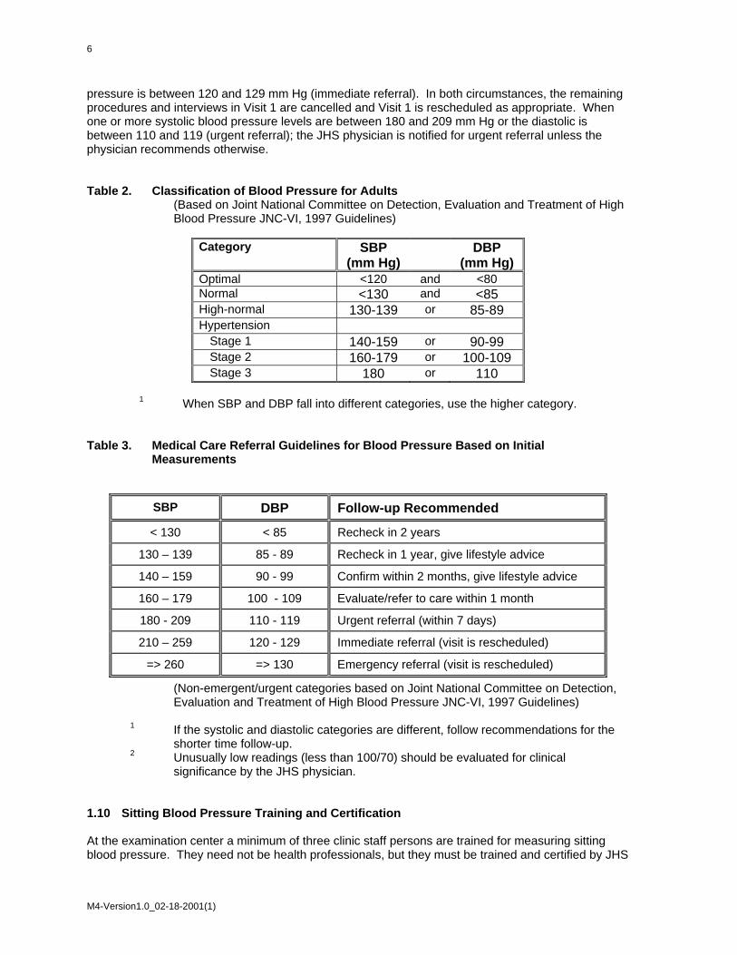
pressure is between 120 and 129 mm Hg (immediate referral). In both circumstances, the remaining procedures and interviews in Visit 1 are cancelled and Visit 1 is rescheduled as appropriate. When one or more systolic blood pressure levels are between 180 and 209 mm Hg or the diastolic is between 110 and 119 (urgent referral); the JHS physician is notified for urgent referral unless the physician recommends otherwise. Table 2. Classification of Blood Pressure for Adults
(Based on Joint National Committee on Detection, Evaluation and Treatment of High Blood Pressure JNC-VI, 1997 Guidelines)
Category SBP
(mm Hg) DBP
(mm Hg) Optimal <120 and <80 Normal <130 and <85 High-normal 130-139 or 85-89 Hypertension
Stage 1 140-159 or 90-99 Stage 2 160-179 or 100-109 Stage 3 180 or 110
1 When SBP and DBP fall into different categories, use the higher category. Table 3. Medical Care Referral Guidelines for Blood Pressure Based on Initial
Measurements
SBP DBP Follow-up Recommended
< 130 < 85 Recheck in 2 years
130 – 139 85 - 89 Recheck in 1 year, give lifestyle advice
140 – 159 90 - 99 Confirm within 2 months, give lifestyle advice
160 – 179 100 - 109 Evaluate/refer to care within 1 month
180 - 209 110 - 119 Urgent referral (within 7 days)
210 – 259 120 - 129 Immediate referral (visit is rescheduled)
=> 260 => 130 Emergency referral (visit is rescheduled)
(Non-emergent/urgent categories based on Joint National Committee on Detection, Evaluation and Treatment of High Blood Pressure JNC-VI, 1997 Guidelines)
1 If the systolic and diastolic categories are different, follow recommendations for the
shorter time follow-up. 2 Unusually low readings (less than 100/70) should be evaluated for clinical
significance by the JHS physician. 1.10 Sitting Blood Pressure Training and Certification At the examination center a minimum of three clinic staff persons are trained for measuring sitting blood pressure. They need not be health professionals, but they must be trained and certified by JHS
M4-Version1.0_02-18-2001(1)
7
in the blood pressure measurement technique. Observers should also have experience in relating to people. The first training session begins with a description and demonstration of the correct blood pressure measurement procedure. Trainees listen to the 1st (training) audiocassette tape, taking the test sequences until they are confident they can identify 1st and 5th phase Korotkoff sounds. Then, they use the 2nd tape until they have passed the test. After passing the second test, they are given the 3rd tape test. Alternated with the tapes are actual practice sessions with live subjects under the instruction and observation of the training supervisor. Some live practices may be done with a standard stethoscope, but most employ the Y-tube stethoscope. After the first day of training, each trainee is given a cuff and manometer (no stethoscope) to take home and practice control of the valve. This is done by wrapping the cuff on a jar or bottle and alternately pumping up and dropping the mercury at a steady rate of 2 mm per second. After two or three sessions, trainees are also given a stethoscope to practice on family or friends. Out-of-class practice is very important to build confidence. Practice time allowed in class is not enough without outside practice time. Once each trainee has passed the third tape test, he or she does at least two live readings with the training supervisor on the Y-tube stethoscope. The readings must agree within 4 mm and the average must agree within 3 mm. If they do not, the trainee needs additional practice with tapes and live subjects. The training supervisor also verifies that the trainee understands and follows proper procedures. Additional time is allowed for instruction and mastering the use of the Random-Zero device. Trainees are certified after passing tape tests 2 and 3 (tape 4 is held in reserve for recertification) and at least 2 live readings. Observers are recertified every six months by taking and passing tape 3 or 4 and two readings with the blood pressure supervisor on an Y-tube stethoscope. It is the responsibility of the Examination Center to conduct recertification procedures and report to the Coordinating Center when the procedures are complete. 1.10.1 Tapes The JHS Study uses four tapes of Korotkoff sounds. Tape 1 is a training tape. Tape 2 is a practice tape. Tapes 3 and 4 are test tapes. A new trainee listens to tape 1, goes to tape 2 and repeats it as often as necessary. Tape 3 is taken as a test. It, too, may be repeated if necessary. Tape 4 is held in reserve for the six-month recertification. Tapes 3 and 4 are alternated thereafter for recertification. 1.10.2 Using the Cronus Stop Watch with the Prineas Blood Pressure Tapes The Cronus stopwatch, model 3-S, is an interval timer and is the preferred timing device to be used with the training tapes. Of the various options, it seems to be the simplest and easiest to read. It is generally available at a local sporting goods store. The address of the manufacturer is: Cronus Precision Products, Inc. 2895 Northwestern Parkway Santa Clara, CA 95051 USA If only Phase 1 and Phase 5 are learned, two ordinary stopwatches may be used. Using one in each hand, both are started at the beep; one is stopped when the first Korotkoff sounds are heard and the other stopped at Phase 5. The interval watch is preferred even if Phase 4 is not being recorded because it is much easier to change one's mind if sounds change, and it is easier to read. 1. Turn on the stopwatch and press the reset button. 2. Start the tape, wearing headphones. At the beginning of each tape is a timing sequence, with no
Korotkoff sounds. When the beep is heard, start the watch by pressing the button at the top.
M4-Version1.0_02-18-2001(1)

8
Stop the watch with the button at the top when the second beep is heard. Record the time elapsed to the nearest 10th of a second on the top of the student form.
3. Press reset button. When the tape announces sequence 1, start the watch at the beep. 4. When the first Korotkoff sound is heard, stop the watch with the button at the top. Record the
time elapsed to the nearest 10th of a second. The watch continues to run internally. 5. When the Phase 5 (disappearance) is heard, stop the watch. Record the time elapsed to the
nearest 10th of a second. Press reset. Repeat steps 3 through 5 for each sequence. Remember that the tapes were designed for a special timing device. The answers given are double the stop watch values. At the end be sure to turn off the stopwatch in order to save batteries. To score the tests, add all the sequences, and divide by the number of sequences. The average should be within plus or minus one second.
1.10.3 Y Tube Stethoscope Observations Y Tube stethoscope observations are made in conjunction with the blood pressure tapes during initial training and for biannual quality control. The trainer has the observer-trainee go through the entire blood pressure measurement procedure using a quality control checklist. The observer and trainer listen with the Y Tube and record the values on separate sheets. Two measurements on one subject are obtained. Measurements by the trainer and the trainee should agree within 4 mmHg on any one reading (systolic or diastolic) and averages should agree within 3 mmHg. 1.11 Quality Control To ensure the accuracy of the blood pressure measurements throughout the study, quality control measures are developed at the Coordinating Center and applied at the Examination Center. These measures include: 1. recruitment of the most qualified personnel
2. standardized training and certification
3. retraining and recertification
4. biannual observation of data collection by supervisors, using the checklist given in Appendix 3. One checklist is used for each technician and sent to the Coordinating Center each quarter.
5. frequent staff meetings to provide feedback
6. editing of data, both manual and by computer
7. a quality assurance program administered by the Coordinating Center
8. biannual simultaneous Y Tube observation of each technician by the blood pressure supervisor
9. equipment maintenance program 1.12 Technician Training and Quality Control Blood pressure technicians are trained by the clinic coordinator or their designee prior to participant recruitment. New technicians hired after the start of the study are trained locally by the Study Coordinator or a designated "Blood Pressure Supervisor". Recertification occurs every six months. Prior to certification, each technician is required to have a clinical hearing test. The Coordinating Center directs a blood pressure quality assurance program to review six-monthly data. This includes quality analysis and review of blood pressure data, comparing means for each
M4-Version1.0_02-18-2001(1)

9
technician with the values for all technicians. These statistics are adjusted for weight, age and sex of the participants. Digit preference is also monitored for each technician. 1.13 Equipment Maintenance The Examination Center is responsible for the proper operation and maintenance of its equipment. Maintenance responsibility is assumed by the blood pressure supervisor and all staff are instructed to report any real or suspected equipment problems to that person promptly. All checks, inspections, cleanings and problems indicated are documented and recorded by date in a permanent log. Problems and solutions are also recorded. A copy of this log is given in Appendix 4. 1.13.1 Random Zero and Standard Sphygmomanometers The Random Zero manometer is inspected once a week and the standard manometer once a month. These inspections include a check of:
1. the zero level of the standard manometer
2. mercury leakage
3. manometer column for dirt or mercury oxide deposit
4. condition of all tubing and fittings.
The equipment is cleaned if inspection indicates it is needed, or at least once a year. Specific instructions for the random zero device are provided in Appendix 1, and for the standard manometer in Appendix 2. In addition, every two months the accuracy of the random zero instrument is checked using a standard manometer and an Y connection, as described in Appendix 4. 1.14 Referral of Hypertensives As shown in Table 4, blood pressure referral levels are made based on the findings of the JHS examination which are consistent with the recommendations given in the sixth report of the Joint National Committee on Detection, Evaluation, and Treatment of High Blood Pressure (1997). The average of the first and second resting blood pressure readings is used.
M4-Version1.0_02-18-2001(1)

10
2.0 ANKLE/BRACHIAL SYSTOLIC BLOOD PRESSURE PROTOCOL 2.1 Purpose The ratio of the ankle blood pressure to the arm blood pressure provides a measure of lower extremity arterial disease (circulation problems). The ankle-arm index (AAI) is reduced to less than 1.0 when there is obstruction to blood flow in the legs. The AAI is a non-invasive measure of atherosclerosis. The AAI is associated with atherosclerotic disease in other vascular beds and predicts cardiovascular mortality. 2.2 Equipment 1. 8 megahertz Doppler pen probe with built-in speakers
2. 9 volt alkaline batteries
3. Doppler conducting jelly
4. Standard mercury column sphygmomanometer: Wall-mounted Baumanometer
5. Calibrated V-Lok BP cuffs in four sizes:
• 2 large adult cuff
• 2 small adult cuffs
• 4 regular adult cuffs
• 3 thigh cuffs
6. Tissues to remove conducting jelly
7. Black eyeliner pencil 2.3 Exclusions
1. Persons with venous stasis ulceration or other pathology that precludes placing a BP cuff around the ankle (e.g. open wounds).
2. Persons with rigid arteries such that an occlusion pressure cannot be reached. If the artery cannot be occluded before the mercury column reaches 300 mmHg, the participant is excluded.
3. Persons with bilateral amputations of legs.
4. Subjects who fit any of the above categories are recorded as missing data.
5. If a subject has undergone a mastectomy of the right breast or has other reasons to omit right arm pressures, the left arm will be used for measures.
M4-Version1.0_02-18-2001(1)

11
2.4 Set-Up Procedure
1. Ask participant to remove shoes and stockings so that the ankles are bare to mid-calf.
2. Participant is positioned on examination in a flat to semi flat position with trunk no more than 45 degrees from surface.
3. Keep participant supine for at least five minutes before measuring BP.
4. Place three BP cuffs on the participant (be sure to check for appropriate cuff size)
a) Right arm
b) Right ankle
c) Left ankle If the right arm cannot be used, the left may be used. This change must be noted on form. Table 4. Determination of Cuff Size Based on Arm and Ankle Circumference
Cuff Size Arm and Ankle Circumference
Small Adult < 24 cm
Adult 24 to 32 cm
Large Adult 33 to 41 cm
Thigh > 41 cm
5. Apply ankle cuffs with midpoint of bladder over posterior tibial artery, with lower end of
bladder approximately 3 cm above medial malleolus (prominence on medial side of ankle). See Figure 1.
2.5 Procedure 2.5.1 General Guide to Blood Pressure Readings
1. Following any previous inflation, wait at least 30 seconds after cuff has completely deflated.
2. By closing the thumb valve and squeezing the bulb, inflate the cuff at a rapid but smooth continuous rate to the maximal inflation level (30 mmHg above systolic pressure). This measure is described in greater detail below.
3. The examiner’s eyes should be level with the mid-range of the manometer scale and focused at the level to which the pressure will be raised.
4. By opening the thumb valve slightly, and maintaining a constant rate of deflation at approximately 2 mmHg per second, allow the cuff to deflate.
5. Listen throughout the entire range of deflation, past the systolic reading (the pressure where the first regular sound is heard) for 10 mmHg. Two subsequent beats should be heard for any valid systolic blood pressure reading.
6. Deflate the cuff fully by opening the thumb valve.
7. Neatly enter systolic readings in the spaces provided on the form.
M4-Version1.0_02-18-2001(1)

12
2.5.2 Right Arm Systolic Blood Pressure Measurement
1. Attach right arm cuff tubing to manometer.
2. Apply ultrasound jelly over brachial artery. The brachial artery is located just medial to the center of the cubital fossa.
3. Locate brachial artery using Doppler pen probe.
4. Hold the Doppler Probe absolutely still. It can easily slip off the artery.
5. Measure the systolic blood pressure:
a. Inflate cuff quickly to maximal inflation level (30 mmHg above systolic pressure).
b. Deflate at 2 mmHg/second, to appearance of systolic pressure.
c. Follow down for 10 mmHg. Two subsequent beats should be heard for any valid systolic blood pressure reading.
d. Remove Doppler pen probe.
e. Deflate cuff quickly and completely.
f. Disconnect the right arm cuff from the manometer and connect to the right ankle cuff.
6. Neatly record systolic blood pressure.
7. Disconnect the right arm cuff from manometer. 2.5.3 Right and Left Ankle Systolic Blood Pressure Measurement
1. Connect right ankle cuff to the manometer.
2. Apply ultrasound jelly over posterior tibial artery. This artery is located on the calf and is most easily located at the medial malleolus of the ankle
3. Locate posterior tibial artery using Doppler pen probe.
4. Hold the Doppler probe absolutely still. It can easily slip off the artery.
5. Measure the systolic blood pressure:
a. Inflate cuff quickly to maximal inflation level (30 mmHg above systolic pressure).
b. Deflate at 2 mmHg/second to appearance of systolic pressure.
c. Follow down for 10 mmHg. Two subsequent beats should be heard for any valid systolic blood pressure reading.
d. Remove Doppler pen probe.
e. Deflate cuff quickly and completely.
6. Neatly record ankle systolic blood pressure.
7. Disconnect right ankle cuff from manometer. Connect left ankle cuff to manometer and repeat procedure.
NOTE: If the posterior tibial pulse cannot be found with palpation or Doppler pen probe, use the dorsalis pedis artery for the measurement. Have another examiner verify the absent posterior tibial pulse.
M4-Version1.0_02-18-2001(1)

13
Figure 2. Right and Left Ankle Cuff Placement
M4-Version1.0_02-18-2001(1)

14
2.5.4 Repeating the Ankle-Arm Repeat the sequence in reverse order
a. left ankle
b. right ankle
c. right arm 2.6 Tips for Ankle-Arm Measurements 2.6.1 Using the Doppler Push button in to turn on and gradually turn the volume up. Now place the probe over the artery (brachial or posterior tibial). The frequency used is 8 Megahertz (vibrations of 8 million times per second). In order to hear the signal above background noise, the instrument must be pushed in toward the artery. Angling the beam upstream improves the signal. For deeper vessels, the unit will have to be tilted back toward perpendicular, but NOTE: the instrument works poorly or not at all if held fully perpendicular to the flow. It must always be angled into and IN LINE with the flow. Please see figure below. Figure 3. Doppler Probe Position
In some places along the posterior tibial artery, there is anatomical hiding of the vessel by muscle or tendons. Move up or down the vessel a little to find the best signal above background noise. The purpose of the Doppler is to determine that blood is or is not flowing under the cuff. For correct interpretation, the probe MUST be centered directly over the artery and must not be moved while inflating the cuff. Please note that the Doppler unit turns itself off after 5 minutes automatically. This may occur in the middle of a measurement.
• Mark the location of maximal pulse or Doppler signal on the brachial artery and both posterior and tibial arteries with eyeliner pencil to improve the speed and accuracy of localizing them the second time and to help maintain position.
M4-Version1.0_02-18-2001(1)

15
• Hold the Doppler pen absolutely still while inflating and deflating the cuff; moving a few
millimeters will lose the pulse.
• Always use enough jelly to ensure good contact. 2.6.2 Maintenance of Doppler
• KEY POINT: Use only ultrasound gel
• The probe: The probe consists of two crystals; one for transmitting the ultrasound waves and the other for receiving the reflected waves. If either crystal is damaged, the probe will not work properly or will not work at all. The crystals are covered by epoxy resin. This resin is attacked by any gel or liquid containing the chloride ion. Therefore, NEVER use ECG paste or cream as the contact medium between the skin and the crystals. Use AQUASONIC or any gel made for ultrasonic physical therapy equipment. In an emergency use any surgical jelly or lubricant, even Vaseline or mineral oil. Remove the gel after use with a soft tissue. If the probe has dried gel on it, wash it off under running water. Do NOT scrape off the gel because this may damage the epoxy coating. Do NOT autoclave the probe. Gas sterilization is OK.
• KEY POINT: To preserve the battery, turn off the unit immediately after measurements.
• The battery: As the battery runs down, the signal will get weaker to the point where the instrument just doesn’t work. Most batteries run down because the instrument has been left turned on. It takes less than a minute to make a blood pressure measurement. Turn the unit off immediately after removing it from the skin. Use an alkaline-type replacement 9-volt transistor radio battery.
• Abnormal Doppler Noise: On occasion there are unusual noises from the Doppler that do not indicate a problem with the Doppler. The normal sound will become obvious with experience in performing this test. Following are some common complaints and their causes.
• Popping noises when the probe is first placed on the skin. Scratchy sound at first. Cause: bubbles in the gel that are moving and/or popping. Also hair movement can cause noise. Remedy: Use a new glob of gel that looks clear, push down enough so hair is immobilized, and just wait a few seconds for things to settle down. If the noise isn’t there when the probe is clean (no gel) and suspended in the air, the Doppler and/or probe are probably not at fault.
• Bad static when the dry probe is moved in the air. Cause: a loose connector where the probe connects to the instrument, a broken shield wire in the cable either at the connector or as it comes out of the probe. This can be diagnosed by wiggling the wire or connectors gently. There is NORMALLY some static generated when the cable is flexed, but it isn’t severe. Remedy: QC Officer will arrange to replace probe or get connectors fixed.
• High-pitched tone. Cause: radio interference from a mobile service, police station nearby, even another Doppler working nearby. Usually occurs near large open windows, rarely in the center of the building. Remedy: Move to another room.
• Howling noise when the probe with gel on it is held or laid on a table. Cause: acoustic feedback through the probe acting as a microphone. If it doesn’t occur without gel on the probe, everything is OK.
M4-Version1.0_02-18-2001(1)

16
2.6.3 Guidelines for Blood Pressure
a. Determining the Maximal Inflation Level (MIL)
Determine the pressure to which to inflate the cuff for the measurement of the systolic blood pressure. This assures that the cuff pressure at the start of the reading exceeds the systolic blood pressure and allows you to hear the first Korotkoff sound. The maximal inflation level (MIL) should be measured specifically for the ankle-arm index measurement, using the Doppler, independently from its measurement for the regular blood pressure measurement. The procedures for determining MIL are as follows:
• Attach the cuff tubing on the arm to the conventional mercury
sphygmomanometer.
• Locate the brachial pulse with the Doppler.
• Inflate the cuff until the brachial pulse is no longer heard.
• Deflate the cuff quickly and completely.
• Inflate the cuff to 30 mmHg above the Doppler systolic pressure for all subsequent readings.
• Repeat the MIL if the first attempt was unsatisfactory or you have had to readjust the cuff after measuring the MIL. Wait 30 seconds before making a second attempt if the first is unsatisfactory.
• If the brachial pulse is still heard at a level of 270 mmHg or higher (which means that the MIL is 30 mmHg or higher) repeat the MIL. If the MIL is still 300 mmHg, terminate the blood pressure measurements and write in “300/MIL” on the form. On the Report of Findings, indicate the blood pressure at the level heard. Refer the participant to see their doctor based on the blood pressure taken with a stethoscope. The Doppler will always be higher.
b. The systolic value is the pressure level at which you hear the first of two or more swishing
sounds in the appropriate rhythm. (Note: A single sound heard in isolation [i.e., not in rhythmic sequence] before the first of the rhythmic sounds [systolic] does not alter the interpretation of blood pressure).
c. Record all readings to the nearest even digit, rounding up (i.e., read any value that
appears to fall exactly between the markings on the mercury column to the next higher even marking).
d. Make readings at the top of the meniscus, or rounded surface of the mercury columns.
e. When the pressure is released too quickly from a high level, a vacuum is formed above
the mercury and the meniscus is distorted. Allow a few moments for it to reappear before reading the manometer or doing a repeat measurement.
M4-Version1.0_02-18-2001(1)

17
2.7 Quality Assurance 2.7.1 Training Requirements Staff performing the ankle-arm index measurements should be research technicians or clinicians previously trained in taking research blood pressure measurements. In addition, training should include:
• Read and study manual
• Attend Jackson Heart Study training session on techniques (or observe administration by experienced examiner)
• Practice on volunteers
• Compare measurements with those made by experienced colleagues (Goal: obtain measurements within ± 2 mm Hg of that observed by a trainer)
• Discuss problems and questions with QC officer 2.7.2 Certification Requirements
• Complete training requirements
• Recite exclusion criteria
• Conduct exam on two volunteers while being observed by QC officer listening with Doppler
M4-Version1.0_02-18-2001(1)

18
3.0 AMBULATORY BLOOD PRESSURE MONITORING 3.1 Introduction and Equipment Medifacts, Ltd. is a clinical research company dedicated to the evaluation of pharmaceutical and biological products using Ambulatory Blood Pressure Monitoring (ABPM) technology. The technical operations and procedures discussed in this manual have been custom designed for use only in the conduct of the Jackson Heart Study (JHS). 3.1.1 Support Personnel: U.S. Support Staff:
• Michael Hackworth • Jeff Heilbraun • Keith Klischer • Ron Murray • Karen Nesmith • Meryl Poland
3.1.2 Address and Phone Number: If you have any questions or problems related to conducting ABPM for this protocol, please do not hesitate to call (24 hours a day, 7 days a week) at one of the following numbers: Medifacts, Ltd. 1401 Rockville Pike Suite 300 Rockville, MD 20852 301-279-0500 Phone 1-800-333-6460 Toll Free 301-424-0675 Fax [email protected] 3.1.3 Monitor Vs. Mercury Column Calibration Step by Step Instructions Each ABPM unit must be calibrated prior to its use within the study. The calibration of an ABPM unit need only be done once. Each unit must be calibrated against each Mercury column to be used in correlation readings during the study. To check the calibration of the monitor, use the following procedures:
1. Obtain a full-size mercury sphygmomanometer (mercury column).
2. Disconnect the cuff hose from the mercury column tube.
3. Connect the T-Tube to the monitor Luer-Lok™ connector and the mercury column, and one of the cuffs provided by Medifacts.
4. Wrap the cuff around a rigid cylinder (see below).
M4-Version1.0_02-18-2001(1)

19
Figure 4. Calibration Setup
5. Turn the monitor ON. Press the START/STOP button on the monitor. The monitor display
should read approximately 165-170mmHg when the cuff is inflated completely. Note and compare the readings on the monitor and the mercury column as the pressure bleeds down. Overall, the monitor readings should be within three (3) millimeters or 2% of the mercury column. At the end of the procedure, the monitor displays an error code.
6. When completed, turn the monitor off and disconnect the T-tube from the monitor. Disconnect
the cuff hose and mercury column from the T-tube. 7. Repeat these steps for each monitor provided and switching the associated cuff. Each monitor
must be calibrated against each mercury column to be used during the study. This procedure will be done once with each ABPM and does not need to be repeated with each participant.
8. To complete the table located in Section 3.0, you will record the mean difference between the
observed mercury column and monitor values during the calibration procedure in the corresponding row/column. In the first row of the table, you will record the serial number of each mercury column that your site may be using in this study. In the first column, you will record the serial number of each monitor provided to your site.
9. If the mean difference observed is > 4, please contact Medifacts for return of the ABPM unit. EXAMPLE: In this example, we are calibrating monitor 207-00256 and Mercury Column (MC1) serial number (SN) 1527954. After the monitor was manually prompted once, the following readings were observed: ABPM MC1 Observed Reading Reading Difference 160 162 2 135 136 1 100 102 2 74 76 2 The mean difference is approximately: 2
M4-Version1.0_02-18-2001(1)

20
Using the example above the table would appear as follows: MC1 MC2 MC3 MC4
ABPM SN: 1527954 SN: SN: SN:
SN: 207-00256 2 SN: SN:
Note: Your observations and comparisons will vary during this procedure. Figure 5. Monitor Vs. Mercury Column Calibration Table MC1 MC2 MC3 MC4
ABPM SN: SN: SN: SN:
SN: SN: SN: SN: SN: SN: SN: SN: SN: SN: SN: SN: SN: SN: SN: SN: SN: SN: SN: SN: SN: SN: SN: SN: SN: SN: SN: SN: SN: SN: SN: SN: SN: SN: SN: SN: SN: SN: SN:
M4-Version1.0_02-18-2001(1)

21
SN: MC1 MC2 MC3 MC4
ABPM SN: SN: SN: SN:
SN: SN: SN: SN: SN: SN: SN: SN: SN: SN: SN: SN: SN: SN: SN: SN: SN: SN: SN: SN: SN: SN: SN: SN: SN: SN: SN: SN: SN: SN: SN: SN: SN: SN: SN: SN: SN: SN: SN: SN:
3.1.4 Assembly of the Dell Computers Follow the instructions below to assemble the computer system for your scheduled training. Please call Medifacts if you have any questions or concerns regarding the assembly of the computer system. 1. Turn your computer so that the backside is facing you.
2. Attach the DATA KEY to the 25 pin parallel port, located on the back of your computer. The data key is a small (2" x 2") black plastic device with a 25 pin serial port on one end and a 25 pin parallel
M4-Version1.0_02-18-2001(1)

22
port on the other. On one side of the data key, there is a white arrow covered by a number. This arrow should be face up and point toward the computer. Tighten the screws finger tight.
Figure 6. Dell Computer Data Key
3. Attach the gray ABPM Spacelabs MONITOR CABLE to the 9 pin serial port, located just to the right
of the data key port. Tighten the screws finger tight.
4. Insert the TELEPHONE CORD into the computer. On the right side of the computer with the back still facing you there is a small rectangular “modem”. Press the small square on the left side of the modem to pop the telephone plug out. Insert one end of the telephone cord into this jack and plug the other end into the dedicated telephone jack on your wall.
Figure 7. Dell Computer Diagram
Modem
Telephone Cord On/Off
5. Connect the male end of the AC Adapter into the back of the computer at the far right end. Then insert the female end of the POWER CORD into the AC adapter and the male end of the power cord into a surge protector or the wall outlet.
6. Turn your computer so that the front faces you. Open the top lid of your computer by sliding the tab located in front center to the right (→).
7. You are now ready to turn your computer ON. The ON/OFF or POWER button is located on the left side of the computer. Slide the button towards you. Listen for a double BEEP tone, which indicates that the internal modem is connected.
8. The MEDICOM programming software will load itself automatically. 3.1.5 Dell Computers: To adjust the display screen BRIGHTNESS/CONTRAST, do the following: Adjustment Key Combination • Decrease brightness Fn ↓ • Increase brightness Fn ↑ • Decrease contrast Fn → • Increase contrast Fn ←
M4-Version1.0_02-18-2001(1)

23
3.1.6 Assembly of the IBM Computers The following are instructions for assembling the IBM computer system. Please call Medifacts if you have any questions or concerns regarding the assembly of the computer system.
1. Turn your computer so that the back side is facing you
2. Lower the panel covering the back right side. Connect the male end of the AC Adapter into the back of the computer at the far right end. Insert the end of the POWER CORD into the AC adapter and the male end of the POWER CORD into a surge protector or the wall outlet.
3. Attach the MONITOR CABLE to the 9 pin serial port, located just to the left of the POWER CORD attachment.
4. Attach the DATA KEY to the 25 pin parallel port, located on the back of your computer to the left of the MONITOR CABLE. The data key is a small (2" x 2") black plastic device with a 25 pin serial port on one end and a 25 pin parallel port on the other. On one side of the data key, there is a white arrow covered by a number. This arrow should be face up and point toward the computer. Tighten the screws, finger tight.
Figure 8. IBM Data Key
5. Turn your computer around so that the front is now facing towards you.
6. The ON/OFF or POWER switch is located on the back left side of the computer. Slide the button backward (away from you).
7. Inserting the TELEPHONE CORD. The modem outlet will be located on the back left side below the ON/OFF switch. Insert one end of the TELEPHONE CORD into this space. Plug the other end of the telephone cord into the dedicated telephone line port on your wall.
8. Open the top of your computer by sliding the tabs located on either side of the computer. You are now ready to turn your computer ON. The MEDICOM software will load itself automatically.
9. To adjust the display screen BRIGHTNESS/CONTRAST, use the slide switch located on the lower right hand side of the display screen.
10. The computer mouse is a red ball located in the center of the keypad. The mouse buttons are located below the spacebar.
11. The disk drive to be used during computer “backup” is located on the left front side of your computer.
M4-Version1.0_02-18-2001(1)
24
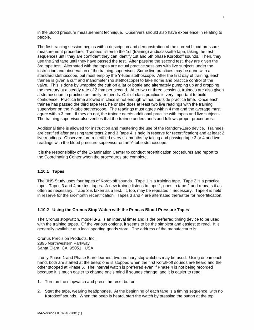
3.1.7 Assembly of the Compaq Computers The following are instructions for assembling the Compaq computer system. Please call Medifacts if you have any questions or concerns regarding the assembly of the computer system. 1. Turn your computer so that the back is facing towards you. Figure 9. Compaq Computer Diagram
2. Connect the male end of the AC Adapter into the back of the computer into the round port farthest to
the left. Insert the female end of the POWER CORD into the AC adapter and the male end of the POWER CORD into a surge protector or the wall outlet.
3. Lower the panel covering the back left side. Attach the gray, MONITOR CABLE to the 9 pin serial port, located farthest to the left on the back of the computer.
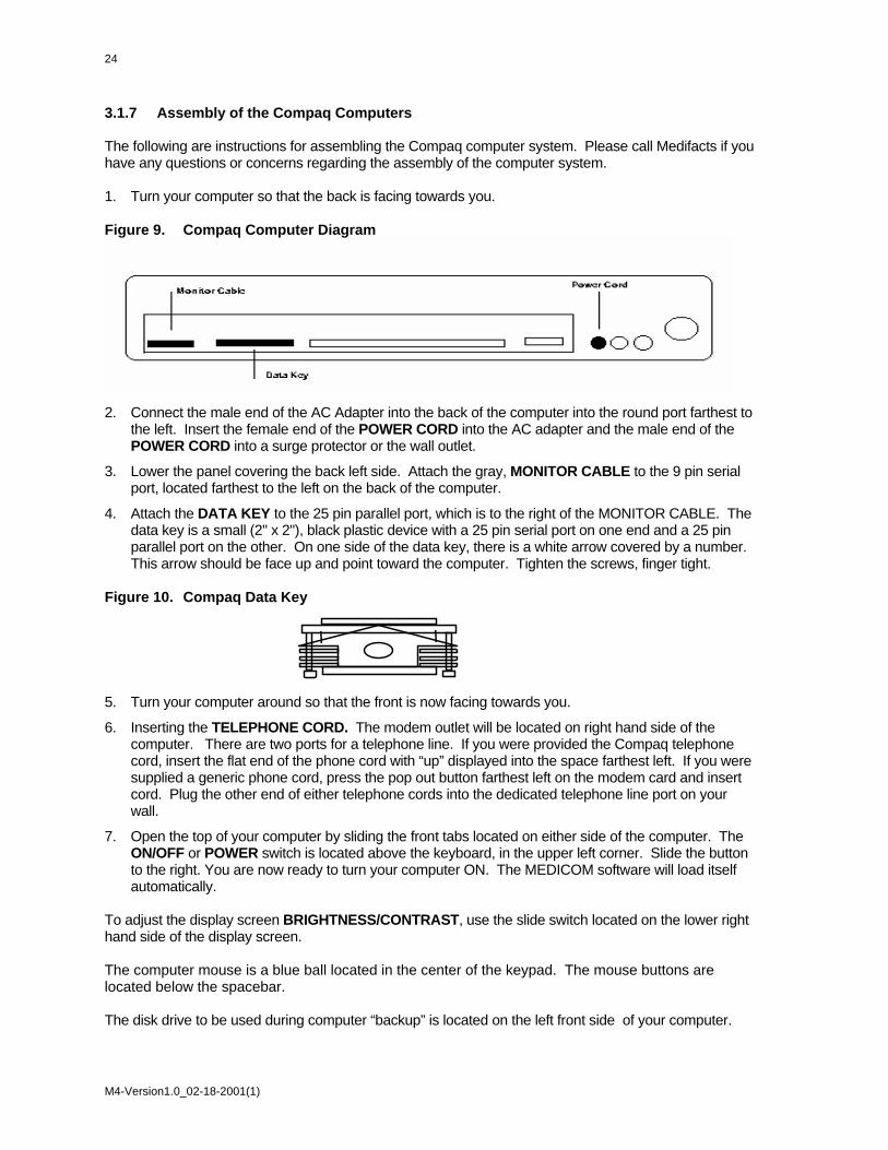
4. Attach the DATA KEY to the 25 pin parallel port, which is to the right of the MONITOR CABLE. The data key is a small (2" x 2"), black plastic device with a 25 pin serial port on one end and a 25 pin parallel port on the other. On one side of the data key, there is a white arrow covered by a number. This arrow should be face up and point toward the computer. Tighten the screws, finger tight.
Figure 10. Compaq Data Key
5. Turn your computer around so that the front is now facing towards you.
6. Inserting the TELEPHONE CORD. The modem outlet will be located on right hand side of the computer. There are two ports for a telephone line. If you were provided the Compaq telephone cord, insert the flat end of the phone cord with “up” displayed into the space farthest left. If you were supplied a generic phone cord, press the pop out button farthest left on the modem card and insert cord. Plug the other end of either telephone cords into the dedicated telephone line port on your wall.
7. Open the top of your computer by sliding the front tabs located on either side of the computer. The ON/OFF or POWER switch is located above the keyboard, in the upper left corner. Slide the button to the right. You are now ready to turn your computer ON. The MEDICOM software will load itself automatically.
To adjust the display screen BRIGHTNESS/CONTRAST, use the slide switch located on the lower right hand side of the display screen. The computer mouse is a blue ball located in the center of the keypad. The mouse buttons are located below the spacebar. The disk drive to be used during computer “backup” is located on the left front side of your computer.
M4-Version1.0_02-18-2001(1)
25
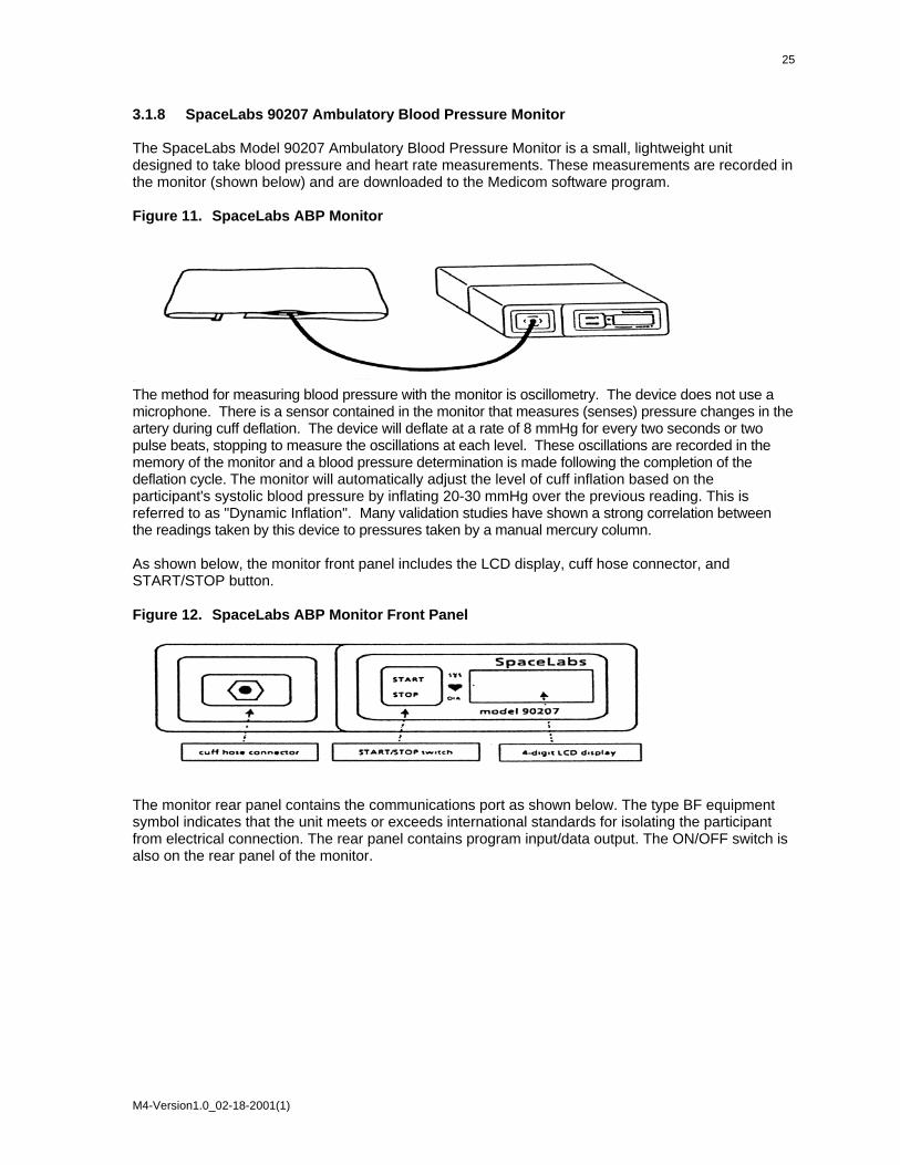
3.1.8 SpaceLabs 90207 Ambulatory Blood Pressure Monitor The SpaceLabs Model 90207 Ambulatory Blood Pressure Monitor is a small, lightweight unit designed to take blood pressure and heart rate measurements. These measurements are recorded in the monitor (shown below) and are downloaded to the Medicom software program. Figure 11. SpaceLabs ABP Monitor
The method for measuring blood pressure with the monitor is oscillometry. The device does not use a microphone. There is a sensor contained in the monitor that measures (senses) pressure changes in the artery during cuff deflation. The device will deflate at a rate of 8 mmHg for every two seconds or two pulse beats, stopping to measure the oscillations at each level. These oscillations are recorded in the memory of the monitor and a blood pressure determination is made following the completion of the deflation cycle. The monitor will automatically adjust the level of cuff inflation based on the participant's systolic blood pressure by inflating 20-30 mmHg over the previous reading. This is referred to as "Dynamic Inflation". Many validation studies have shown a strong correlation between the readings taken by this device to pressures taken by a manual mercury column. As shown below, the monitor front panel includes the LCD display, cuff hose connector, and START/STOP button. Figure 12. SpaceLabs ABP Monitor Front Panel
The monitor rear panel contains the communications port as shown below. The type BF equipment symbol indicates that the unit meets or exceeds international standards for isolating the participant from electrical connection. The rear panel contains program input/data output. The ON/OFF switch is also on the rear panel of the monitor.
M4-Version1.0_02-18-2001(1)

26
Figure 13. SpaceLabs ABP Monitor Rear Panel
The serial and the model numbers are provided above the battery panel. On the reverse side of the battery panel there are abbreviated operating instructions for the monitor. The monitor runs with 4 alkaline AA (1.5V) batteries. You will be provided with an adequate supply before the study starts. Please make sure that fresh batteries are put into the monitor before each attempted monitoring period. Figure 14. ABPM Battery positions
If the monitor becomes soiled, use a soft, damp cloth and mild detergent mixed with water to wipe the exterior of the monitor. Clean the air hose connector with isopropyl alcohol. 3.1.9 BPM Cuff and Pouch The cuff wrap (with the air bladder removed) and the pouch are machine washable on “delicate” cycle only. Do not wash with bed linens, gowns, or in a large, commercial-type washers. Small soiled or stained areas may be cleaned by gentle scrubbing with a sponge or cloth soaked in a mild soap and water solution. Although not necessary, the cuff wrap and carrying pouch may also be sterilized
M4-Version1.0_02-18-2001(1)

27
by ethylene oxide (EtO) sterilization methods using standard hospital procedures. Use standard aeration techniques after sterilization. 3.1.9.1 Bladder Insertion When inserting the bladder back into the cuff use only your fingers, do not use pencils, pens, or other hard objects as damage to the bladder may occur. Fold or roll up the bladder inside the cuff as shown below. Manipulate the cuff as necessary to unroll the bladder so that all the folds have been removed. The bladder should lie flat within the cuff. Figure 15. Bladder Insertion (1) The bladder may be installed with the hose exiting the second cuff opening. However, the bladder must be positioned with its long side toward the center of the cuff. Figure 16. Bladder Insertion (2)
Right Arm Left Arm Opening Opening
BLADDER (Shown inserted into cuff wrap for left arm application)
ARTERY
3.1.9.2 Bladder Removal: To remove the bladder, pull the bladder through the hose exit opening. Once the bladder has been removed, mate the hook and loop surfaces before washing.
M4-Version1.0_02-18-2001(1)

28
3.2 Operations Overview for Jackson Heart Study 3.2.1 Technology Ambulatory Blood Pressure Monitoring (ABPM) will be completed using the Medifacts research software, Spacelabs 90207 Oscillometric Device, and a laptop with modem. 3.2.2 ABPM Service / Support Medifacts, Ltd., Rockville, MD (1-800-333-6460) will supply a laptop and a proprietary centralized software program to the clinical research center. Medifacts will also supply ABP monitors, a full range of cuffs, carrying pouches, shoulder strap belts, batteries, and any other disposable supplies or equipment necessary to perform ambulatory blood pressure monitoring (ABPM) on study participants. A Medifacts representative will provide, an on site training program on the use of ABPM and will review the ABPM instruction manual prior to the first scheduled ABPM. 3.2.3 ABP Monitoring Schedule The 24-hour ABP monitoring will occur one time during the protocol. Participants should report to the study center during the study-specified time frame. The Medicom software will evaluate the quality control criteria when the device is returned and the data is downloaded to the laptop. If the ABPM does not meet the quality control criteria, it may be repeated within the next 6 months. If a report fails quality control, the clinical center should call Medifacts immediately after transmitting the file to discuss the reasons for report QC failure. • ABPM Application Day Participants will be instructed in the proper use, application, and removal of the ABPM device during the clinic visit. • ABPM Removal Day Participants return to the clinic 24 hours after the previous morning’s application, for the removal of the ABPM unit. If the participant is unable to return to the clinic to have the unit removed, a representative from the Jackson Heart Study will arrange for device retrieval. 3.2.4 Office Visit Participants will have the ABPM applied at the end of their visit procedures for the visit day. There is no required time window for ABPM application. The ABPM will be applied to the participant and correlation readings performed. After successful completion of the correlation procedure, the study investigator or coordinator will prompt a valid “Beginning of Test” reading. 3.2.5 ABPM Cuff / Arm Circumference The ABP monitor will be applied to the participant’s NON-DOMINANT arm. This will be the arm opposite of that being used for office “cuff” BP measurements. A centimeter measuring tape will be provided to determine the participant’s arm circumference measurement, which is obtained on an extended arm at the midpoint of the upper arm. Medifacts will provide a range of ABPM cuffs to each site:
M4-Version1.0_02-18-2001(1)

• Youth cuff range: 17- 26 cm
• Adult regular cuff range: 24 - 32 cm
• Adult large cuff range: 32 - 42 cm
• Adult extra large range: 38 - 50 cm The non-dominant arm used for ABPM cuff placement will be recorded on the Pre-ABPM form that will be retained as a source document. 3.2.6 Correlation Readings Each ABPM will be preceded by the correlation of simultaneous blood pressure (BP) readings between the ABP monitor and the office mercury sphygmomanometer via a "T" tube connector. With the participant in a SEATED position, three to five valid readings will be taken to compare the office BP with the readings taken by the ABP monitor. These readings will be recorded on the Pre-ABPM form. The mean of the three selected office diastolic blood pressures and the mean of the three corresponding valid ABPM diastolic blood pressures may not differ by more than + 7mmHg. The ABPM device is automatically programmed for “5 live” readings in order to accomplish this validation process. If the correlation procedure is unsuccessful, the ABPM must be reprogrammed to obtain an additional “5 live” readings and the process must be repeated. When recording the observed readings use the time as displayed on the ABP monitor. After successful completion of the correlation procedure, a mark identifying proper placement of the cuff will be drawn on the participants’ arm. See Section 3.4 for a detailed instruction. 3.2.7 Beginning of the Test The beginning of the 24-hour monitoring period is identified after the successful completion of the correlation procedure. The quality control criteria for ABPM readings are based on the 24-hour Beginning of Test to Conclusion of Test period. Following the successful completion of the correlation procedure, the study coordinator will manually initiate the ABP monitor to take a reading. For the purposes of quality control, this initiated reading will designate the “Beginning of Test” (Time Monitoring Begun). Using the clock display on the ABP monitor, the date and time of this initiated reading will be recorded in the Pre-ABPM form. All readings obtained prior to the valid “Beginning of Test” reading will be designated with an edit code of CR. The Medicom software program is designed to disregard any reading with an edit code of CR when calculating quality control. 3.2.8 ABPM Device - Data Display Blinding The ABP monitor will be automatically programmed to blind the data. Five "live" (un-blinded) readings will be displayed at the beginning of the monitoring for the correlation readings. 3.2.9 Monitor Inflation Frequency The monitor will be automatically programmed to inflate at the following frequency: • Every 20 minutes for 24 hours 3.2.10 Monitor Deflation The ABPM device will be automatically programmed to deflate at a rate of 8mmHg per 2 heartbeats.
M4-Version1.0_02-18-2001(1)

30
3.2.11 ABPM Duration The total duration of each ABPM will be 24-hours from the “Beginning of Test” initiated reading. The participant must be instructed on the following items:
• Maintain his/her usual activity level during the monitoring period.
• Do not engage in strenuous exercise or activities during the monitoring period.
• Hold arm still and extended at his/her side during an automated or, if required, manually prompted reading.
• Avoid removing the ABPM monitor during the monitoring period.
• Review information regarding the general care of the ABP monitor.
• The individual is instructed not to shower or take a bath during the ABP monitoring period
• The individual will be instructed on proper re-application of the ABPM unit if removal is necessary during the 24-hour period.
3.2.12 Conclusion of the Test The conclusion of the monitoring is considered to be the last valid blood pressure reading obtained. Prior to removal of the ABP monitor, a manual reading must be initiated to conclude the test. The "Conclusion of Test" (Time Monitoring Ended) reading should not be initiated until at least 24-hours following the “Beginning of Test” reading. After assuring that the reading is valid (i.e., no error codes) the monitor is then removed. The “Conclusion of Test” time and date is recorded in the Post-ABPM Form using the display clock on the ABP monitor. If it becomes necessary for a participant to remove the ABPM device, a manual reading should still be initiated to conclude the test. The “Conclusion of Test” time and date should be recorded by the participant. This information is required for the Post-ABPM Form. 3.2.13 Data Editing Criteria Data is edited based on the following criteria:
• Minimum Valid Systolic = 060 mmHg
• Maximum Valid Systolic = 261 mmHg
• Minimum Valid Diastolic = 030 mmHg
• Maximum Valid Diastolic = 151 mmHg
• Minimum Valid Sys – Dia = 015 mmHg
• Maximum Valid Sys - Dia = 140 mmHg
• Minimum Valid Heart Rate = 030 bpm
• Maximum Valid Heart Rate = 150 bpm
If a reading falls outside of these limits, it will be considered as not valid and is thereby eliminated from the quality control process. Data will be further edited using a process termed by Medifacts as “Suspect Data”. This process identifies readings, which fall within the editing criteria described above, but are two standard deviations greater than or less than either the 24-hour mean or the hourly mean for that reading.
M4-Version1.0_02-18-2001(1)

3.2.14 ABPM Quality Control Criteria The Medicom research software automatically evaluates the quality control criteria. One of the following messages will be displayed on the computer screen to indicate the results of a monitoring: QUALITY CONTROL = PASSED or QUALITY CONTROL = FAILED The software will automatically place a “QC” code (1 = PASS or 3 = FAIL) on the first page of the ABPM report to indicate the quality control results. The following are the minimum quality control criteria:
• There must be a minimum of 24-hours of data following the “Beginning of Test” time
• Each hour must have a minimum of 1 valid reading
• There must be a minimum of 54 valid readings (75% of the 72 programmed readings) If a participant monitoring FAILED to meet the minimum quality control criteria, please contact Medifacts to discuss criteria for failure prior to the participant’s departure from the Exam Center. There may be allowance for acceptance of this monitoring or the participant may be asked to repeat the ABPM procedure. 3.2.15 Repeat ABPM After discussion with Medifacts, a monitoring failing to meet acceptable quality control criteria may be repeated. All repeat monitorings must be scheduled to occur within 1 month of the failed attempt. 3.2.16 Night Shift Participants Participants who work third shift (i.e. sleep during the day and work over night) can participate in the ABPM. 3.2.17 Participant Documentation Each participant will be supplied with a Participant Instruction Handout. An activity diary card will not be used during this study 3.2.18 Participant Report Two hard copies of the participant’s ABPM report will be sent to the clinical center on a weekly basis. A copy of the ABPM report should be kept in the participants’ source documents. 3.2.19 Monthly Activity Report An ABPM activity report will be sent to the clinical center at the end of each month. The report should be reviewed carefully and any discrepancies should be reported to Medifacts. These updates can be communicated via phone, fax or e-mail.
M4-Version1.0_02-18-2001(1)

32
3.3 Introduction to the Medicom ABPM Software 3.3.1 Introduction The Medifacts Ambulatory Blood Pressure Monitoring (ABPM) communications software is a proprietary software program written exclusively for use when conducting ABPM research. Your version of the software has been programmed specifically for this protocol. Do not make any adjustments to the programming or setup of the software without first speaking to your Medifacts data manager. The software will allow you to program a monitor, download the ABPM data, check quality control, run data statistics (if applicable), enter required demographic and activity information (if applicable) and transfer data to Medifacts via modem. Actual software applications may vary depending on protocol requirements. 3.3.2 Turning the Computer On Be sure that the data key and monitor cable are attached to their appropriate ports on the computer (see Section 3.1). Turn your computer ON using the computer ON/OFF switch. The computer will automatically load the MEDICOM program software. The computer will then display the Windows screen. The desired study protocol must then be selected by double clicking on the appropriate icon. The following logo will then appear on the screen: M E D I F A C T S MEDICOM - Version 3.41 Copyright 1999 Medifacts Ltd.
01-01-2000 09:00:00 The date and time that appear are based on a real time clock/calendar inside of your computer. Please verify that the TIME and DATE are correct. If so, press the <ENTER> key and the "MEDICOM MAIN MENU" will appear. If not, you can update this information the first time you program a monitor. 3.3.3 Software Menus and Their Functions The MEDICOM software contains two principal menus and two secondary menus. The two principal menus are:
• The MAIN MENU
• The EDIT DATA MENU The two secondary menus are:
• The SETUP MENU
• The DISPLAY DATA MENU
M4-Version1.0_02-18-2001(1)

All of the programming functions that you require will begin with a selected option from one of these four menus. The following pages provide a visual representation of each menu and a description of each of the menu options. Figure 17. Medicom Main Menu
MEDICOM - MAIN MENU 1. Program Monitor 2. Read Monitor Data 3. Edit Data 4. Setup 5. DOS Exit Select an Option: 0
The menu options are: 1. Program Monitor:
This option allows you to program participant information into the monitor prior to attaching it to the participant.
2. Read Monitor Data: This option allows you to read or download data from the monitor to the computer after the participant monitoring is completed. The data is then stored on the computer hard drive.
3. Edit Data: When a data file IS ALREADY in the current computer memory, this option allows you to view the EDIT DATA menu. When a data file is not already in the computer’s current memory this option allows you to select a data file from the hard drive and then view the EDIT DATA menu.
4. Setup: This option, although rarely used, allows you to revise the program setup. A Medifacts representative will call you with instructions if this option becomes necessary. There is a secondary menu behind the setup option. The EQUIPMENT SETUP menu is explained in further detail on the following page.
5. DOS Exit: This option allows you to exit the Medicom program to the Windows main screen. This option will be used once a week for a weekly backup of data (see elsewhere in this section).
To select an option, type the number of your choice and press the <ENTER> key.
Figure 18. Medicom Equipment Setup Menu
EQUIPMENT SETUP 1. Communications 2. Printer 3. Test Mode 4. Select Paths & Data 5. Exit & Save Select an Option: 0
M4-Version1.0_02-18-2001(1)

34
Except to change from TEST MODE to PATIENT MODE this menu is rarely used. If it becomes necessary to make other setup changes, a Medifacts representative will instruct you in its use. To access this secondary menu, type “4” for SETUP from the Medicom MAIN MENU and press the <ENTER> key. You will see the following menu options:
1. Communications:
This option allows you to setup the modem to transmit ABPM data to Medifacts.
2. Printer: This option allows you to setup the serial port for the monitor cable. Your version of the Medicom software does not contain the print function.
3. Test Mode: This option is used only ONCE during the protocol and allows you to change the automatic file ID generator from the TEST MODE to the PATIENT MODE. This will be done only once during the protocol (see section 8.0 of this tab). The setup screen will usually be to change programming modes from TEST MODE to PATIENT MODE.
4. Select Paths and Data: This option allows you to change the data path.
5. Exit and Save: This option allows you save any changes that have been made to the program setup.
To select an option, type the number of your choice and press the <ENTER> key. Figure 19. Medicom Edit Data Menu
EDIT DATA MENU 1. Read Disk Data File 2. Edit Patient Data 3. Edit Activities 4. Display Data 5. Quality Control 6. Send Data 7. Main Menu Select an Option: 0
Edit Data Menu Options: 1. Read Disk Data File:
This option allows you to retrieve a participant data file from the computer’s memory (hard drive) where it is stored after "Reading Monitor Data" (downloading).
2. Edit Patient Data: This option allows you to add or change participant information on the participant ABPM data file.
3. Edit Activities: This option allows you to enter or change participant activity information in a participant data file, if required in the protocol. This option allows you to view each reading taken by the ABPM monitor.
4. Display Data: This option allows you to graphically view a data file. There is a secondary menu behind the display data option. The DISPLAY DATA menu is explained on the following page (section 3.4).
5. Quality Control: This option allows you to re-run the Quality Control analysis.
M4-Version1.0_02-18-2001(1)

6. Send Data: This option allows you to send a copy of the data file to Medifacts via modem.
7. Main Menu: This option allows you to return to the Medicom Main Menu.
To select an option, type the number of your choice and press the <ENTER> key. Figure 20. Medicom Display Data Menu DISPLAY DATA MENU 1. Display raw data 2. Display hourly average Select an Option: 0 Display Data Menu Options: 1. Display raw data:
This option allows you to graphically display each blood pressure and heart rate reading taken during the required monitoring period.
2. Display hourly average:
This option allows you to graphically display the hourly average of each blood pressure and heart rate reading taken during the required monitoring period. The display will also indicate the number of readings used to calculate the average.
To select an option, type the number of your choice and press the <ENTER> key. 3.3.4 ABPM File in Current Memory In order to work with an ABPM file that has been downloaded from the monitor and stored on the computer hard drive, the file must be in the “Current Memory” of the computer. An ABPM file is in “Current Memory” if the “ID” and “NAME” appear across the bottom of the computer screen. If the ID and NAME do not appear across the bottom of the screen or if the information that appears on the screen is not the file that you are interested in, you can do one of the following to load the requested file into “Current Memory.” 3.3.5 Loading an ABPM File into Current Memory 3.3.5.1 To Load an ABPM File from the Main Menu If there is not a file in “Current Memory” and you are looking at the MAIN MENU, type “3” for “EDIT DATA” and press the <ENTER> key. ABPM files are stored by the FILE-ID. To select the desired FILE-ID, use the appropriate arrow keys to move the "highlight" until the FILE-ID# becomes shaded and press the <ENTER> key, or at the "Enter file name" prompt, type the correct FILE-ID# in the space provided and press the <ENTER> key. Once a file is selected, the EDIT DATA Menu appears on the screen. The “NAME and ID #” of the selected ABPM file will appear in the lower left corner of the screen. 3.3.5.2 To Load an ABPM File from the Edit Data Menu If there is a file in “Current Memory” and you are looking at the EDIT DATA MENU, type “1” for READ DISK DATA FILE and press the <ENTER> key. After completing this, follow the instructions listed in section 5.1.
M4-Version1.0_02-18-2001(1)
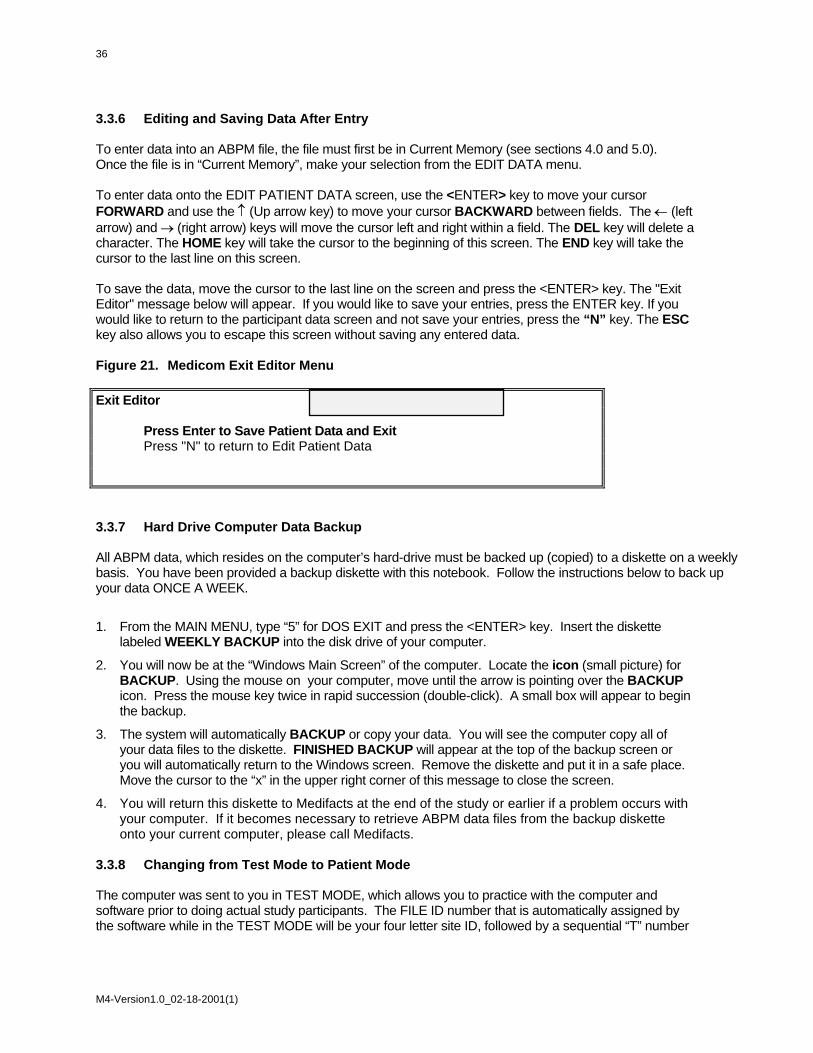
36
3.3.6 Editing and Saving Data After Entry To enter data into an ABPM file, the file must first be in Current Memory (see sections 4.0 and 5.0). Once the file is in “Current Memory”, make your selection from the EDIT DATA menu. To enter data onto the EDIT PATIENT DATA screen, use the <ENTER> key to move your cursor FORWARD and use the ↑ (Up arrow key) to move your cursor BACKWARD between fields. The ← (left arrow) and → (right arrow) keys will move the cursor left and right within a field. The DEL key will delete a character. The HOME key will take the cursor to the beginning of this screen. The END key will take the cursor to the last line on this screen. To save the data, move the cursor to the last line on the screen and press the <ENTER> key. The "Exit Editor" message below will appear. If you would like to save your entries, press the ENTER key. If you would like to return to the participant data screen and not save your entries, press the “N” key. The ESC key also allows you to escape this screen without saving any entered data. Figure 21. Medicom Exit Editor Menu Exit Editor Press Enter to Save Patient Data and Exit Press "N" to return to Edit Patient Data 3.3.7 Hard Drive Computer Data Backup All ABPM data, which resides on the computer’s hard-drive must be backed up (copied) to a diskette on a weekly basis. You have been provided a backup diskette with this notebook. Follow the instructions below to back up your data ONCE A WEEK.
1. From the MAIN MENU, type “5” for DOS EXIT and press the <ENTER> key. Insert the diskette labeled WEEKLY BACKUP into the disk drive of your computer.
2. You will now be at the “Windows Main Screen” of the computer. Locate the icon (small picture) for BACKUP. Using the mouse on your computer, move until the arrow is pointing over the BACKUP icon. Press the mouse key twice in rapid succession (double-click). A small box will appear to begin the backup.
3. The system will automatically BACKUP or copy your data. You will see the computer copy all of your data files to the diskette. FINISHED BACKUP will appear at the top of the backup screen or you will automatically return to the Windows screen. Remove the diskette and put it in a safe place. Move the cursor to the “x” in the upper right corner of this message to close the screen.
4. You will return this diskette to Medifacts at the end of the study or earlier if a problem occurs with your computer. If it becomes necessary to retrieve ABPM data files from the backup diskette onto your current computer, please call Medifacts.
3.3.8 Changing from Test Mode to Patient Mode The computer was sent to you in TEST MODE, which allows you to practice with the computer and software prior to doing actual study participants. The FILE ID number that is automatically assigned by the software while in the TEST MODE will be your four letter site ID, followed by a sequential “T” number
M4-Version1.0_02-18-2001(1)

to indicate a test file (Example: KNEX-T01). When programming a monitor in the TEST MODE, you will see a second flashing message box displaying "WARNING TEST MODE ACTIVE". You MUST change into the PATIENT MODE prior to beginning the study. Once you have changed to PATIENT MODE you may no longer perform monitorings on practice participants. When you change to PATIENT MODE, the FILE ID that is automatically assigned will be the 4 letter, site-specific code followed by a three-digit sequential number. To complete the change from the "EQUIPMENT SETUP" menu, type “3” for TEST MODE and press the <ENTER> key. You will see the message “CHANGE TO PATIENT MODE?”. Type “Y” for yes in the blank box and press the <ENTER> key to return to the "EQUIPMENT SETUP" menu. Type “5” to EXIT & SAVE and press the <ENTER> key. The computer is now in PATIENT MODE. 3.4 Programming and Downloading the Monitor 3.4.1 Programming the Monitor To program the monitor, you will do the following: 1. Put fresh batteries in the monitor:
The battery compartment is located on the back of the monitor. To open the battery door, pull back and up on the battery compartment latch. The lid will pop open. Follow the schematic diagram on the inside of the lid to insert the batteries. After inserting the batteries, replace the cover and secure the latch.
NOTE: It is very important to insert new batteries in the ABPM for each subject monitoring. DO NOT attempt to do two monitorings without changing batteries.
2. Attach the monitor to the monitor cable:
With the monitor turned OFF (see the black ON/OFF switch on the bottom of the monitor), attach the "Monitor Programming Cable" to the data INPUT/OUTPUT area on the bottom of the monitor. Make sure that the ARROWS on the monitor and on the cable point toward each other. Attach the monitor cable to the computer (See Section 3.1).
3. Turn the monitor ON:
Turn the monitor ON using the black ON/OFF switch. If the batteries are inserted correctly and the connection is satisfactory, "9999" or “1999” will appear on the monitor display screen. The first digit may switch between a nine and a one.
4. Program monitor:
Each monitor MUST be programmed on the day that it is going to be applied to the participant because the ABPM start time and date are programmed by the computer. If the participant cancels their appointment, the monitor MUST be re-programmed on the day of the participant’s rescheduled ABPM monitoring visit.
From the "MEDICOM MAIN MENU", type “1” for PROGRAM MONITOR and press the <ENTER> key. You will see the "PROGRAM SpaceLabs 90207" screen with the message "Checking SpaceLabs Monitor" on the bottom. You will hear a soft "beep" tone from the monitor and you will see a dark bar with a blinking cursor next to the "NAME" FIELD. The message at the bottom of the screen will tell you to "Enter Patient Data".
M4-Version1.0_02-18-2001(1)

38
Figure 22. Medicom Program Monitor Screen Program SpaceLabs 90207 V3.41
NHLBI-Jackson Heart Study
Name: __ __ __ - __ __ -__ __ __- __ __ __ __- __ __ ID #: JSA1-001 Note: Date: 04/07/2000 Time: 09:10
Press Enter to Continue 5. Enter the participant name field:
When programming a monitor, you will be asked for the NAME. With the blinking cursor next to "NAME", type in the PARTICIPANT NAME FIELD. The NAME will be created using the following components to maintain the participant’s confidentiality rights.
The participant's three initials: [MAX] If there is no middle initial use a hyphen: [M-X] The participant's Date of Birth: [31-MAY-1985] dd-mmm-yyyy The event code: [11] (ABPM #1) [21] (ABPM #2)
The first digit of the event code represents the ABPM visit and the second digit represents the attempt.
EX: PARTICIPANT NAME FIELD: MAX-31-MAY-1956-11
If the ABPM for the first visit fails Quality Control, then the repeat attempt will have an event code of “12”.
EX: REPEAT PARTICIPANT NAME FIELD: MAX-31-MAY-1956-12 6. When you finish the “NAME” field, press the <ENTER> key and record this information on the
correlation worksheet and FILE ID log which are located in the back of this notebook. Your cursor will move to the “NOTE” field. Typically, this field is left blank (See section 1.7).
7. Record the File ID:
The FILE ID is entered automatically by the software and is used to store the ABPM data on the computer hard drive. Record the FILE ID on the correlation worksheet. Please be sure that the FILE ID displayed on the computer corresponds to the correct protocol.
8. Entering “Note” section information:
There is only one line for notes during programming. In this study, there is no required information for the NOTE lines. Please leave this line BLANK. Press the <ENTER> key to move to the “DATE” field.
9. Verify the date:
The “DATE” is usually in the MM-DD-YYYY format for U.S. protocols or DD-MM-YYYY for European protocols and is automatically entered for you by the internal clock/calendar in the computer. Please verify that the DATE is correct. If so, press the <ENTER> key and your cursor will move to the
M4-Version1.0_02-18-2001(1)

“TIME” field. If the date is incorrect, type in the correct “DATE” in the correct format for your protocol (i.e., U.S. versus European).
10. Verify the time:
The “TIME” is in 24-hour format and is automatically entered for you by the internal clock/calendar in the computer. Please verify that the TIME is correct. If so, press the <ENTER> key and the software will program the monitor. If the time is incorrect, type in the correct “TIME” in the HH: MM format.
11. Verify that DONE appears - you have completed programming:
After pressing the <ENTER> key to program the monitor, you will see the message “WAIT”, followed in a few seconds by the message “DONE PRESS ENTER TO CONTINUE”. When you see this message, the programming is complete and you may press the <ENTER> key to return to the MAIN MENU. Turn your monitor OFF, disconnect it and it is ready to apply to the participant.
12. Monitor Labels:
If this is the only monitor that you are programming for that day, you can turn your computer OFF. At the end of this notebook, you will find monitor labels. After programming a monitor, record the Name field, File ID, and monitoring date on a label. Affix the label to the programmed monitor so that it can be selected and applied to the intended participant. If you have other monitors to program, repeat the above steps.
3.4.2 Using the File ID Logs At the end of this notebook, you will find sets of FILE ID LOGS containing the FILE IDs that have been pre-assigned to your site. The logs are used to record the NAME FIELD for each ABPM FILE ID done during the protocol. The FILE ID will be automatically assigned to the participant's ABPM file by the MEDICOM software each time you program a monitor. The following are detailed instructions to complete the FILE ID logs. The File ID log MUST be filled in each time a monitoring is done so you can readily identify an ABPM file to a particular participant in each of these studies. • The FILE ID is a numbering sequence made up of a four-letter code and a sequential, three-digit
number. The FILE ID is used to label the ABPM file and store it in the computer. • The PARTICIPANT NAME FIELD is used to identify the participant data recorded during the
monitoring period. • The PATIENT ID is also used to identify the participant data recorded during the monitoring period. • The DATE MONITORED column will indicate the date that the monitor was applied to the participant. • The FILE SENT column will indicate that the participant monitoring is complete, you have
downloaded the file from the monitor and stored it in the computer, entered all required participant documentation information, and have SENT (transmitted) the file to Medifacts via computer modem.
• The REPORT RECEIVED column will be used to indicate that you have received a hard copy of the
participant report from Medifacts. When you program your monitor, turn to your FILE ID LOGS and find the FILE ID that the computer has assigned in the FILE ID column. 1. Record the "PARTICIPANT NAME FIELD" created when programming the monitor (See section
1.5). 2. Record the PATIENT ID assigned for the participant.
M4-Version1.0_02-18-2001(1)
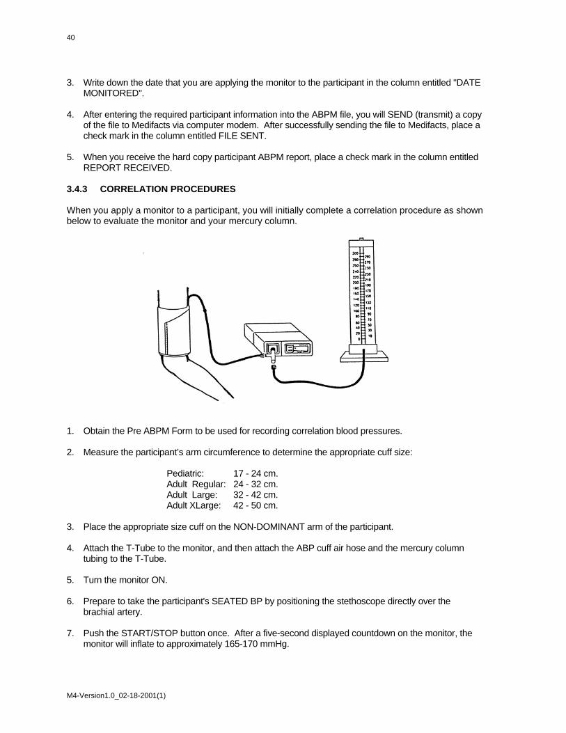
40
3. Write down the date that you are applying the monitor to the participant in the column entitled "DATE
MONITORED". 4. After entering the required participant information into the ABPM file, you will SEND (transmit) a copy
of the file to Medifacts via computer modem. After successfully sending the file to Medifacts, place a check mark in the column entitled FILE SENT.
5. When you receive the hard copy participant ABPM report, place a check mark in the column entitled
REPORT RECEIVED. 3.4.3 CORRELATION PROCEDURES When you apply a monitor to a participant, you will initially complete a correlation procedure as shown below to evaluate the monitor and your mercury column.
1. Obtain the Pre ABPM Form to be used for recording correlation blood pressures. 2. Measure the participant’s arm circumference to determine the appropriate cuff size: Pediatric: 17 - 24 cm. Adult Regular: 24 - 32 cm. Adult Large: 32 - 42 cm. Adult XLarge: 42 - 50 cm. 3. Place the appropriate size cuff on the NON-DOMINANT arm of the participant. 4. Attach the T-Tube to the monitor, and then attach the ABP cuff air hose and the mercury column
tubing to the T-Tube. 5. Turn the monitor ON. 6. Prepare to take the participant's SEATED BP by positioning the stethoscope directly over the
brachial artery. 7. Push the START/STOP button once. After a five-second displayed countdown on the monitor, the
monitor will inflate to approximately 165-170 mmHg.
M4-Version1.0_02-18-2001(1)

8. As the monitor measures the SEATED BP electronically, observe the mercury column. Record the SEATED systolic and diastolic BP you measured and the SEATED systolic and diastolic BP displayed by the monitor on the correlation worksheet. The monitor displays the systolic BP, diastolic BP and heart rate data, respectively, three successive times within 15 seconds of completion of the BP measurements.
9. If it is necessary to readjust the cuff and if the difference between the Diastolic BP readings is > 5
mmHg and/or the difference between the Systolic BP readings is > 10 mmHg then do the following: 10. Reprogram the monitor. Enter the original “NAME.” A new File ID will be assigned. 11. Check position of the cuff. 12. Check tightness around the arm 13. Arm should be motionless 14. Complete a new Pre ABPM Form for the repeat correlation readings.
NOTE: If the cuff requires adjustment, the correlation readings taken prior to the cuff adjustment must be REJECTED.
15. Repeat the prompted correlation readings up to four more times (a total of 5 live readings are
available for correlation). Record the BP measurements you measured as well as those displayed by the monitor each time. Wait at least 60 seconds between each BP measurement.
Use three successful readings to calculate the average diastolic BP. If at any time there are problems correlating the monitor with the mercury column, please call MEDIFACTS for assistance.
16. The mean (average) difference between three acceptable simultaneous monitor and office mercury
column diastolic BP readings should be calculated to determine if you meet your protocol’s correlation criteria (See Section 3.2.6).
17. When the correlation criteria are met, disconnect the T-Tube (you do not need to turn the monitor
off). Connect the air hose directly to the monitor and place it in the pouch. Attach the pouch to the participant, using either the shoulder strap or belt.
18. After completing the correlation readings prompt for the “Beginning of Test”. The “Beginning of Test”
reading must be valid (i.e., no error codes displayed). 3.4.4 READ MONITOR DATA Prior to removing the monitor (upon completion of the 24-hour monitoring period), the study coordinator will manually initiate a reading to "Conclude the Test". After verifying that a final valid reading was obtained (no error codes observed), the monitor is then removed from the participant, downloaded, and the data reviewed immediately by the coordinator for quality control compliance using the MEDICOM software. The "Conclusion of Test" reading MAY NOT be initiated until it has been at least 24-hours post “Beginning of Test”. To read monitor data (download) from the monitor, turn ON your computer and complete the following steps: 1. Attach the monitor to the monitor cable:
With the monitor turned OFF, attach the "Monitor Programming Cable" to the data INPUT/OUTPUT area on the rear of the monitor. Make sure that the ARROWS on the monitor and cable point toward each other.
M4-Version1.0_02-18-2001(1)
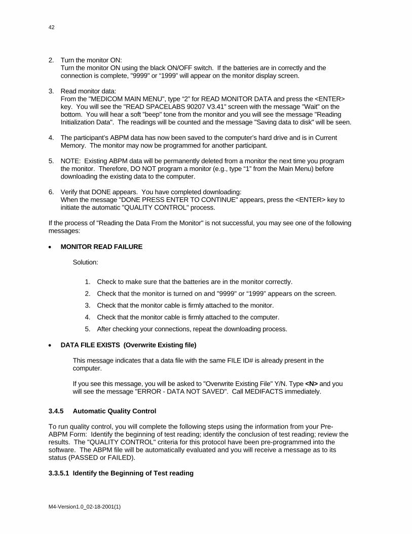
42
2. Turn the monitor ON:
Turn the monitor ON using the black ON/OFF switch. If the batteries are in correctly and the connection is complete, "9999" or “1999” will appear on the monitor display screen.
3. Read monitor data:
From the "MEDICOM MAIN MENU", type “2” for READ MONITOR DATA and press the <ENTER> key. You will see the "READ SPACELABS 90207 V3.41" screen with the message "Wait" on the bottom. You will hear a soft "beep" tone from the monitor and you will see the message "Reading Initialization Data". The readings will be counted and the message "Saving data to disk" will be seen.
4. The participant’s ABPM data has now been saved to the computer’s hard drive and is in Current
Memory. The monitor may now be programmed for another participant. 5. NOTE: Existing ABPM data will be permanently deleted from a monitor the next time you program
the monitor. Therefore, DO NOT program a monitor (e.g., type “1” from the Main Menu) before downloading the existing data to the computer.
6. Verify that DONE appears. You have completed downloading:
When the message "DONE PRESS ENTER TO CONTINUE" appears, press the <ENTER> key to initiate the automatic "QUALITY CONTROL" process.
If the process of "Reading the Data From the Monitor" is not successful, you may see one of the following messages: • MONITOR READ FAILURE Solution:
1. Check to make sure that the batteries are in the monitor correctly.
2. Check that the monitor is turned on and "9999" or “1999” appears on the screen.
3. Check that the monitor cable is firmly attached to the monitor.
4. Check that the monitor cable is firmly attached to the computer.
5. After checking your connections, repeat the downloading process. • DATA FILE EXISTS (Overwrite Existing file) This message indicates that a data file with the same FILE ID# is already present in the
computer. If you see this message, you will be asked to "Overwrite Existing File" Y/N. Type <N> and you
will see the message "ERROR - DATA NOT SAVED". Call MEDIFACTS immediately.
3.4.5 Automatic Quality Control To run quality control, you will complete the following steps using the information from your Pre-ABPM Form: Identify the beginning of test reading; identify the conclusion of test reading; review the results. The "QUALITY CONTROL" criteria for this protocol have been pre-programmed into the software. The ABPM file will be automatically evaluated and you will receive a message as to its status (PASSED or FAILED). 3.3.5.1 Identify the Beginning of Test reading
M4-Version1.0_02-18-2001(1)

The first step in the "QUALITY CONTROL" process is to choose the "Beginning of Test" reading. You will see two prompt boxes. The "EDIT CORRELATION READINGS" prompt box with the first eight readings of the monitoring period on the screen may look like this: Figure 23. Edit Correlation Readings Prompt Box
Edit Correlation Readings # TIME SYS DIA PP HR CODE EDIT ACTIVITIES 1 8:48 152 97 55 71 0 2 8:50 145 89 56 66 0 3 8:52 152 94 58 60 0 4 8:54 155 92 63 53 0 5 9:02 157 92 65 60 0 6 9:17 170 109 61 50 0 7 9:32 169 115 54 63 0 8 9:47 152 102 50 65 0 Below this prompt box, you will see the following “EDIT CORRELATION READINGS” (Beginning of test) prompt box. Figure 24. Edit Correlation Readings (Beginning of Test) Prompt Box
Edit Correlation Readings (Beginning of Test)
Use the arrow keys to move the highlight bar to highlight the reading which represents the
BEGINNING OF TEST
Press "B" to select the highlighted reading
Using the ↑ and ↓ ARROW keys, move the cursor to highlight the appropriate "BEGINNING OF TEST" reading (usually the first reading following the correlation readings) and press "B". At the next prompt box (see below ) you are asked to verify your selection. If you have chosen the correct "BEGINNING OF TEST" reading, press the <ENTER> key. If you selected the incorrect BEGINNING OF TEST reading, press the <N> key to select another reading. Figure 25. Edit Correlation Readings (Beginning of Test) Prompt Box #2
Edit Correlation Readings (Beginning of Test) Does this reading represent the "BEGINNING OF TEST" 4 8:54 155 92 63 53 BEGINNING OF TEST
If Yes press Enter to continue If No press "N" to select another reading
M4-Version1.0_02-18-2001(1)
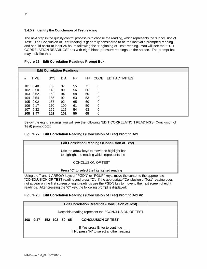
44
3.4.5.2 Identify the Conclusion of Test reading The next step in the quality control process is to choose the reading, which represents the "Conclusion of Test". The Conclusion of Test reading is generally considered to be the last valid prompted reading and should occur at least 24-hours following the "Beginning of Test" reading. You will see the "EDIT CORRELATION READINGS" box with eight blood pressure readings on the screen. The prompt box may look like this: Figure 26. Edit Correlation Readings Prompt Box Edit Correlation Readings # TIME SYS DIA PP HR CODE EDIT ACTIVITIES 101 8:48 152 97 55 71 0 102 8:50 145 89 56 66 0 103 8:52 152 94 58 60 0 104 8:54 155 92 63 53 0 105 9:02 157 92 65 60 0 106 9:17 170 109 61 50 0 107 9:32 169 115 54 63 0 108 9:47 152 102 50 65 0 Below the eight readings you will see the following "EDIT CORRELATION READINGS (Conclusion of Test) prompt box: Figure 27. Edit Correlation Readings (Conclusion of Test) Prompt Box Edit Correlation Readings (Conclusion of Test) Use the arrow keys to move the highlight bar to highlight the reading which represents the CONCLUSION OF TEST Press "C" to select the highlighted reading Using the ↑ and ↓ ARROW keys or "PGDN" or "PGUP" keys, move the cursor to the appropriate "CONCLUSION OF TEST reading and press "C". If the appropriate "Conclusion of Test" reading does not appear on the first screen of eight readings use the PGDN key to move to the next screen of eight readings. After pressing the "C" key, the following prompt is displayed: Figure 28. Edit Correlation Readings (Conclusion of Test) Prompt Box #2
Edit Correlation Readings (Conclusion of Test)
Does this reading represent the "CONCLUSION OF TEST
108 9:47 152 102 50 65 CONCLUSION OF TEST
If Yes press Enter to continue If No press "N" to select another reading
M4-Version1.0_02-18-2001(1)

At this prompt, you are asked to verify your selection. If you have chosen the correct "CONCLUSION OF TEST" reading, press the <ENTER> key to complete the Quality Control evaluation. If you selected the incorrect CONCLUSION OF TEST reading, press the <N> key to select another reading. 3.4.5.3 Review the Results After pressing the <ENTER> key, the software will perform the quality control analysis and will display results in the "QUALITY CONTROL ANALYSIS" prompt box. If the report PASSED Quality Control, you will see: Quality Control: PASSED. Press your <ENTER> key to continue. If the report FAILED Quality Control, you will see: Quality Control: FAILED. The reasons for failure are listed on the screen. Press the <ENTER> key to continue. NOTE: If the report FAILS, call Medifacts immediately after transmitting the file. 3.4.5.4 Failure Analysis Messages: The following messages may be seen when reviewing the "Quality Control Failure Analysis": 3.4.5.4.1 Test duration - HH:MM - Too Short: This message indicates that the total time of the test (from the first valid reading to the last valid reading) is less than the minimum required by the protocol. 3.4.5.4.2 Incorrect Start time: This message indicates that the "Beginning of Test" reading was taken outside of the allowable Beginning of Test time window. 3.4.5.4.3 Consecutive Invalid Hours: This message indicates that there were consecutive hours with less than the minimum required number of valid readings for a valid hour. 3.4.5.4.4 Too Few Valid Hours: This message indicates that the report has less than the minimum number of valid hours. 3.4.5.4.5 Too Few Valid Readings: This message indicates that the report had less than the required minimum number of valid readings. 3.4.5.4.6 Too Few Valid Hours in Period (X): This message indicates that during a specific time period there was less than the required minimum number of valid hours. 3.4.5.4.7 Too Few Valid Readings in Period (X): This message indicates that during a specific quality control period there was less than the required minimum number of valid readings. To better understand why the report failed quality control, you can view the actual blood pressure data (See "Edit Activities" or "Display Data", hourly averages). These options are not available with blinded protocols.
M4-Version1.0_02-18-2001(1)

46
3.4.6 EDIT PATIENT DATA The MEDICOM software is programmed to move you directly to the EDIT PATIENT DATA screen following the completion of the automatic statistics evaluation. This protocol requires the following demographic data to be entered onto the EDIT PATIENT DATA SCREEN of each ABPM file during the download process. This information must be entered prior to modem transmitting the report to Medifacts. When you enter this screen, your cursor will be positioned next to "NAME". Verify that the name field entered during programming is correct and press <ENTER> to continue. To move the cursor between the fields described below, use the <ENTER> or <ARROW DOWN> key (see Section 3.3). After completing the required entries, you will save the data as also described in Section 3.3. An example of the Edit Patient Data Screen is provided at the end of this section. The information that you recorded on the correlation worksheet should be entered onto this screen. Please refer carefully to the correlation worksheet when transferring the information. • NAME:
This information will be entered when programming the monitor. There is no need to re-enter it again unless it is incorrect.
EXAMPLE: MAX-31-MAY-1956-11
• PATIENT ID:
This field will indicate the participants’ identification number. Please enter the seven-digit number.
EXAMPLE: J000003 • QC CODE:
This field will be entered automatically by the MEDICOM software. The field will indicate whether or not the report passes quality control. NO ENTRY NECESSARY.
EXAMPLE: QC CODE 1 (PASS) QC CODE 3 (FAIL) • QC STATUS:
This field, which is used by Medifacts, will contain a quality control status code if the report does not pass quality control. NO ENTRY IS NECESSARY
• SPONSOR:
This field will be pre-coded with the sponsor information. NO ENTRY IS NECESSARY. • CONTACT OCCASION:
This field will be pre-coded with the contact occasion number. NO ENTRY IS NECESSARY. • FORM CODE:
This field will be pre-coded with the form code. NO ENTRY IS NECESSARY. • VERSION NUMBER
This is an internal code used by Medifacts. NO ENTRY IS NECESSARY. • ID NUMBER:
This is the File ID. NO ENTRY IS NECESSARY.
M4-Version1.0_02-18-2001(1)
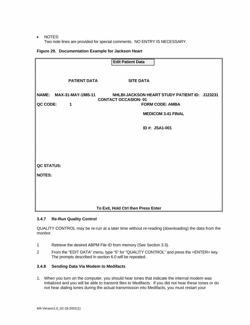
• NOTES:
Two note lines are provided for special comments. NO ENTRY IS NECESSARY. Figure 29. Documentation Example for Jackson Heart
Edit Patient Data PATIENT DATA SITE DATA NAME: MAX-31-MAY-1985-11 NHLBI-JACKSON HEART STUDY PATIENT ID: J123231 CONTACT OCCASION: 01 QC CODE: 1 FORM CODE: AMBA MEDICOM 3.41 FINAL ID #: JSA1-001 QC STATUS: NOTES:
To Exit, Hold Ctrl then Press Enter 3.4.7 Re-Run Quality Control QUALITY CONTROL may be re-run at a later time without re-reading (downloading) the data from the monitor.
1 Retrieve the desired ABPM File ID from memory (See Section 3.3).
2 From the "EDIT DATA" menu, type “5” for "QUALITY CONTROL" and press the <ENTER> key. The prompts described in section 6.0 will be repeated.
3.4.8 Sending Data Via Modem to Medifacts
1. When you turn on the computer, you should hear tones that indicate the internal modem was initialized and you will be able to transmit files to Medifacts. If you did not hear these tones or do not hear dialing tones during the actual transmission into Medifacts, you must restart your
M4-Version1.0_02-18-2001(1)

48
computer (Section 3.1). Prior to sending data, please verify that all required protocol information has been added to the participant data file by reviewing the "Edit Patient Data" screen.
2. Verify that your computer is turned ON and that the telephone cord is connected to the computer modem jack and the telephone jack.
3. Verify that the file that you want to send to Medifacts is in the Current Memory by checking that the “Name and File ID” are present in the lower left corner of the screen.
4. From the "EDIT DATA MENU", type “6” to "SEND DATA" and press the <ENTER> key. You will hear dialing tones and a modem (fax-like) connection.
5. When the data has been sent, "DONE" will appear on the “SEND DATA" screen. Press the <ENTER> key to return to the "EDIT DATA" menu.
M4-Version1.0_02-18-2001(1)

3.5 Participant Instructions 3.5.1 Participant Scheduling (Reminder Call, Attire) The day prior to the ABPM visit, call to remind the participant of his/her visit time. Schedule enough time to do the correlation readings and all other required protocol procedures prior to "Beginning of Test". The participant should wear loose fitting clothing, especially around the arms, as the cuff will be applied directly against the skin. 3.5.2 Wearing The Monitor (Dressing & Sleeping) 1. Review the ON/OFF switch. The participant SHOULD NOT turn the monitor OFF or prompt for any
blood pressure readings during the monitoring period unless it is an emergency or he/she is told to do so by the Study Coordinator. If the monitor is not taking scheduled readings, the participant should look at the monitor screen to see if the time is displayed. If the time is absent, the participant should check the ON/OFF switch. If the time is present, then a technical problem may have occurred and the participant should call the contact person. If the participant calls and indicates that the monitor is not taking scheduled readings, do the following: have the participant flip the ON/OFF switch several times, and then leave it on. Tell the participant to initiate a reading using the STOP/START button. If the monitor takes the reading, have the participant wait at least one-half hour to see if the monitor takes a regularly scheduled reading. If the monitor does not take the reading, have the participant stop the test and return to the office.
2. Show the participant how the monitor is attached to the belt or strap. Make sure the participant
understands how to unhook the belt without dropping the monitor. The monitor SHOULD NOT be worn on the participant's own belt. Use the belt provided.
3. Review dressing procedures. The cuff must be worn against the participant's skin. The cuff hose
must run up the participant's arm over the shoulder and down the other side. Clothing should go on over the top of the cuff and cuff hose. The end of the hose that attaches to the monitor will be visible under the clothing.
4. Demonstrate how the Velcro fastener works with a stress loop to take up excess hose. 5. Inform the participant not to shower or to bathe during the monitoring process. 6. The participant SHOULD NOT remove the cuff during the monitoring unless it is an emergency or
unless instructed to do so by the Study Coordinator. 7. Review undressing procedures. If the cuff was applied correctly, the clothing should be easy to
remove. Remind the participant to be careful not to slide the cuff down the arm when removing a shirt or jacket.
8. Review sleeping procedures. The monitor must be placed in the bed beside the participant. DO
NOT put the monitor on a night stand or any other piece of furniture outside the bed. To muffle the sound, the monitor may be placed inside a pillow case.
9. Mark a “T” on the participant's arm with an ink pen to indicate proper cuff placement in case of cuff
shifting. 3.5.3 Monitoring Instructions 1. Write down the name of a contact person and the telephone number on the Participant Instructions
Handout so the participant can call the office in the event of a monitor problem. 2. Review the Instructions to Participants and Participant handout.
M4-Version1.0_02-18-2001(1)

50
3. The monitor will inflate at 20 minutes for 24 hours. The tones will shut off at night in order to
accommodate sleeping. 4. Demonstrate a monitor error code for the participant (i.e., the hose kink). Explain the five "beep"
tones heard when an error code occurs and review the error code text on the monitor screen. The error code text will remain on the monitor screen for approximately 10 seconds, then it will return to display the time. By demonstrating the error code, you can test the monitor error code system and make sure it is working properly before the participant leaves the office. If one of these error codes occurs, the monitor will then re-try in two minutes to capture the reading.
5. Participants should be instructed that if error codes are continuously observed, that they
should call the contact person immediately. 6. If the monitor screen returns to the clock before the participant was able to look at it, remind the
participant that if an error code occurred, the monitor will repeat the reading in two minutes. If the monitor is attempting a reading twice for every scheduled reading, the participant should call the contact.
7. If the participant continues to get error codes, instruct him/her to call the contact person indicated on
the handout. When speaking to the participant, have him/her relax in a seated position. Then have him/her initiate a reading by pressing the monitor stop/start button. Instruct the participant to read the monitor screen and tell you the error code that appears. Take the appropriate action.
8. Review the double beep tone heard prior to the monitor taking a reading. Following the tone, there is
a five second countdown prior to inflation. If the participant is in a noisy environment, the tone may not be heard.
9. Review the single beep tone heard when the monitor is successful in getting a reading. When the
participant is in a noisy environment, the tone may not be heard. 10. Beeping tones prior to a reading, following a reading, and following an error code are programmed to
be heard during the day. The tone is turned off during the night. 11. Review participant positioning during a reading. If the participant is moving when the monitor begins
to inflate, the participant MUST stop all movement. If standing, instruct the participant to hang his/her arm down to the side and relax all muscle tension. If seated, the participant should rest the cuff arm at approximately heart level in the lap and relax all muscle tension.
12. The participant should attempt to perform a normal day of activity during the monitoring period.
Remind the participant to remain still during a reading. 13. Inform the participant of the ABPM removal /or return to clinic time on the following day. This time
MUST be at least 24 hours after the prompted "Beginning of Test". 3.5.4 Error Codes The monitor is designed to be easily maintained. If any problems develop, use the following information as a guide to solve them. The monitor will display a two-digit event code whenever an event prevents the unit from successfully completing a blood pressure measurement. The two-digit code is preceded by the letters EC, for example EC01. The following list contains a brief description of the event codes which appear on the monitor display. • EC00 A) Too much participant movement
B) Heart rate arrhythmia
M4-Version1.0_02-18-2001(1)

• EC01 Cuff not inflated above systole. The monitor will automatically
inflate the cuff to a higher pressure on the next attempt. • EC02 A) Cuff not properly applied
B) Kinked air hose C) Air leak
• EC03 Participant canceled reading by pressing STOP key. No retry attempt is made
following an “EC03” code. • EC04 Blood pressure measurement not completed in the maximum time allowed. An
occasional “EC04” is generally the result of excessive participant movement. Numerous “EC04” messages indicate an improperly applied cuff.
• EC05 An occasional “EC05” message indicates the monitor’s internal safety mechanisms
aborted the measurement. If these messages appear frequently, the monitor requires service by a qualified service person.
• EC08 Usually, no data. The cuff may have been taken off. • EC09 Blood pressure result unreasonable. Table 5. Error Code Solution Table
ERROR CODE DEFINITION SOLUTION
EC00 Blood pressure could not be detected. Motion artifact (movement or vibrations such as walking or driving)
Remain still when reading is being taken. While driving, rest arm on lap.
EC01 Insufficient inflation of cuff Increase in systolic BP by 20mmHg from the previous reading
Monitor will automatically inflate within 2 minutes to a higher pressure.
EC02
Insufficient pressure in the cuff, <50mmHg. Cuff wrapped loosely (occurs more frequently with the extra large cuff) Cuff slid down arm Hose became kinked during inflation Air leak in cuff bladder or hose
Inspect hose for air leaks or kinks. Wrap cuff on the arm more securely
EC04
Measurement could not be completed within 110 seconds. High systolic BP, consistently > 180mmHg. Excessive participant movement Cuff wrapped loosely.
Remain still when reading is taken. While driving, rest arm on lap. Wrap cuff on the arm more securely
EC08
Too few data entries to accurately determine blood pressure.
Monitor will automatically inflate within 2 minutes
OTHER CODES Usually denote a monitor type malfunction. Contact Medifacts for further instructions
M4-Version1.0_02-18-2001(1)

52
3.5.5 Instructions to Participants 1. The ABP monitor will be worn continually for minimum of 24 hours from the “Beginning of
Test”. 2. Follow guidelines of medication administration until ABP monitor is removed. 3. Remove the ABP monitor ONLY if instructed to do so by the Study Coordinator or in case of
emergency. 4. The “STOP/START” button may be used to stop a reading in an emergency. 5. The ABP monitor will take readings automatically at 20minute intervals for 24 hours. 6. The tones will be heard during the day and turned off at night. Two tones will be heard prior to a
reading. A single beep will be heard if the reading is successful. And five short beep tones will be heard if a reading is unsuccessful.
7. If a reading is NOT successful, an “ERROR CODE” (ex: EC00) will be displayed on the ABPM
LCD. Refer to the other side of this handout for a list of the error code definitions and solutions. 8. If an error code occurs, the monitor will take a repeat reading in two or three minutes. Verify that
the repeat reading is successful by listening for the single beep. 9. If the monitor continually gets error codes (two readings are being attempted for every
automatically scheduled reading) call the study coordinator. 10. When a reading is being taken, avoid movement: Lie, Stand or Sit still and relax. 11. Follow a normal daily schedule of activities during the monitoring period. 12. Do not take a shower or get the monitor wet and avoid use around microwave ovens. 13. Periodically check the cuff placement. Verify that the “Artery Arrow” remains over the “T” placed
on your arm by the study coordinator during the cuff application. If the cuff slips you may adjust it.
14. When sleeping, insert the monitor between a pillow and its pillowcase and place it in bed with
you. Do not place the monitor on a nightstand.
M4-Version1.0_02-18-2001(1)

3.6 Quality Control Grey Areas The minimum quality control criteria for the Jackson Heart Study are as follows:
1. The earliest “Beginning of Test” time = 09:00
2. The latest “Beginning of Test” time = 15:00
3. There must be a minimum duration of 24 hours of data from the “Beginning of Test” time
4. Each hour must have a minimum of 1 valid readings.
5. There must be a minimum of 54 valid readings (75% of the 72 programmed readings). Below is a list of each of the minimum quality control criteria. Following each criterion is a possible reason for failure and a suggested action. Table 6. Grey Area Decision Table
# Quality Control Reason for Failure Decision
Beginning of Test time 08:30-08:59
Over-Ride
1 The earliest “Beginning of Test” time: 09:00. Beginning of Test time
08:29 or earlier Failure, if at all possible repeat ABPM
Beginning of Test time 15:01-15:30
Over-Ride
2 The latest “Beginning of Test” time: 15:00. Beginning of Test time
later than 15:31 Failure, if at all possible repeat ABPM
Total time 23:00 - 23:59 Override * 3
There must be a minimum duration of 24 hours of data from the “Beginning of Test” time.
Total time less than 23:00 Failure, if at all possible repeat ABPM
There is 1 hour with less than 1 valid reading.
Over-Ride
4 Each hour must have a minimum of 1 valid readings. There are consecutive hours with
less than1 valid reading. Failure, if at all possible repeat ABPM
There is total of 50 to 53 valid readings (70% of the 72 programmed readings.
Over-Ride
5 There must be a minimum of 54 valid readings (75% of the 72 programmed readings). There is a total of less than 50
valid readings (less than 70% of the 72 programmed readings.
Failure, if at all possible repeat ABPM
* Note: ONLY if there is a minimum of one valid reading in the last hour. If the last hour is invalid (has no valid readings) and the total time is 23:00 -23:59, then the ABPM should remain a failure and if at all possible repeat ABPM.
M4-Version1.0_02-18-2001(1)
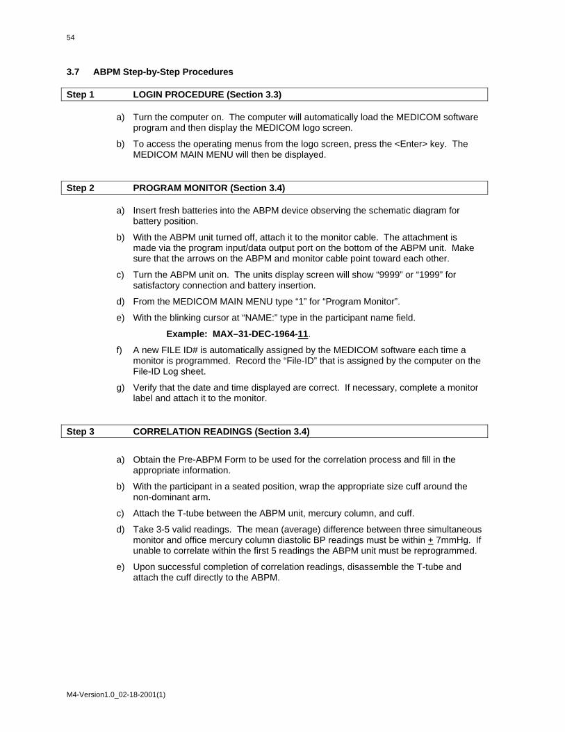
54
3.7 ABPM Step-by-Step Procedures Step 1 LOGIN PROCEDURE (Section 3.3)
a) Turn the computer on. The computer will automatically load the MEDICOM software
program and then display the MEDICOM logo screen.
b) To access the operating menus from the logo screen, press the <Enter> key. The MEDICOM MAIN MENU will then be displayed.
Step 2 PROGRAM MONITOR (Section 3.4)
a) Insert fresh batteries into the ABPM device observing the schematic diagram for battery position.
b) With the ABPM unit turned off, attach it to the monitor cable. The attachment is made via the program input/data output port on the bottom of the ABPM unit. Make sure that the arrows on the ABPM and monitor cable point toward each other.
c) Turn the ABPM unit on. The units display screen will show “9999” or “1999” for satisfactory connection and battery insertion.
d) From the MEDICOM MAIN MENU type “1” for “Program Monitor”.
e) With the blinking cursor at “NAME:” type in the participant name field.
Example: MAX–31-DEC-1964-11.
f) A new FILE ID# is automatically assigned by the MEDICOM software each time a monitor is programmed. Record the “File-ID” that is assigned by the computer on the File-ID Log sheet.
g) Verify that the date and time displayed are correct. If necessary, complete a monitor label and attach it to the monitor.
Step 3 CORRELATION READINGS (Section 3.4)
a) Obtain the Pre-ABPM Form to be used for the correlation process and fill in the appropriate information.
b) With the participant in a seated position, wrap the appropriate size cuff around the non-dominant arm.
c) Attach the T-tube between the ABPM unit, mercury column, and cuff.
d) Take 3-5 valid readings. The mean (average) difference between three simultaneous monitor and office mercury column diastolic BP readings must be within + 7mmHg. If unable to correlate within the first 5 readings the ABPM unit must be reprogrammed.
e) Upon successful completion of correlation readings, disassemble the T-tube and attach the cuff directly to the ABPM.
M4-Version1.0_02-18-2001(1)

Step 4 BEGINNING OF TEST (Section 3.2) a) Prompt the ABPM to take a valid reading to Begin the Test (BOT). Record the BOT
time and date on the Pre-ABPM Form.
b) The BOT time will be transcribed into the participant report when downloading the ABPM data to your computer.
Step 5 REVIEW PARTICIPANT INSTRUCTIONS/PARTICIPANT HANDOUT (Section 3.5)
a) Review the Participant Instructions/Participant Handout to prepare the participant for the 24-hour monitoring period.
b) You may want to demonstrate to your participant an error code by kinking the ABPM cuff tubing.
c) The participant is now ready to leave the office.
Step 6 CONCLUSION OF TEST (Section 3.2)
a) Verify a minimum duration of 24 hours post “BEGINNING OF TEST”. Prompt the ABPM to take a valid reading for the Conclusion of Test. Record the “CONCLUSION OF TEST” time and date on the Post-ABPM Form.
b) Turn the unit OFF. And remove the unit from the participant.
c) Collect the Participant Handout containing GO TO BED and GET UP time information. The handout should be maintained as a source document
Step 7 READ (Download) MONITOR DATA (Section 3.4) a) Attach the ABPM unit to the monitor cable on the computer.
b) Turn the ABPM unit on. Verify “9999” or “1999” on the display screen.
c) At the MEDICOM MAIN MENU, type “2” for “Read Monitor Data”.
Step 8 CHECK QUALITY CONTROL (Section 3.4) a) When “Read Monitor Data” screen says “Done” press the <Enter> key to begin the
automatic quality control program.
b) Follow the prompt box directions on the computer screen. Designate the “BEGINNING OF TEST” reading as noted from the Pre-ABPM Form. Then designate the “CONCLUSION OF TEST” reading as noted from the Post ABPM Form.
c) Review the PASS or FAILED message. If a test fails Quality Control, complete the remaining Step-by-step procedures and call Medifacts at 1-800-333-6460.
Step 9 EDIT PATIENT DATA (Section 3.4)
a) Verify the participant “NAME” information entered during programming is correct.
b) Enter the seven digit patient identification number (PATIENT ID). Exit and save.
M4-Version1.0_02-18-2001(1)

56
Step 10 SEND DATA -Transmit to Medifacts (Section 3.4)
a) From the EDIT DATA MENU, type “6” for “SEND DATA” and press ENTER.
d) If unsuccessful, wait a few minutes and try again. Our Bulletin Board may be busy receiving files from other sites. If still unsuccessful, call Medifacts at 1-800-333-6460.
M4-Version1.0_02-18-2001(1)

APPENDICES
M4-Version1.0_02-18-2001(1)


A-1
Appendix 1 Check Procedures and Maintenance Instructions Random Zero Sphygmomanometer
1. Check cap of manometer column to be sure it fits properly and is tight. The 0 ring or seal must be
seated correctly. Clean cap of any mercury (Hg) beads or dust. The cap should be firmly finger tight. Any time the mercury seems to 'bounce' in the column of either a standard manometer or random zero (R-Z) manometer, it may be due to a loose cap. Check the opening. If it becomes blocked, the mercury column falls too slowly due to a vacuum effect. This may result in false high readings and an erratically oscillating column. This procedure should be carried out for both standard manometers and R-Z's.
2. Remove back of case (two screws at top of face and two at bottom rear of case). Swing back
from the left around the thumbscrew on the right side. Check for spring placement - it should be in line. Tighten all screws except the one holding the bellows plate in place.
3. Wrap an arm cuff around a bottle or can. 4. With reservoir valve open (newer models do not have a reservoir valve) and bellows valve closed,
pump mercury to top of column (270-290 mmHg). If the mercury holds at a steady level for 15 seconds or drops 2-4 mm, that system is airtight.
5. With the high pressure still in the system, close the reservoir and disconnect cuff to see if that
valve holds steady pressure. If a leak is discovered in the reservoir valve, remove hose and valve (with Allen wrench). Valve handle unscrews or lifts off. There are two 0 rings on the valve stem. Clean stem and replace 0 rings. Use stopcock grease in 0 rings and valve.
6. If the closed reservoir valve is tight, but there was a leak with it open, check the inflation
assembly. There may be a leak in the bulb, valve, or cuff. To test the inflation assembly, immerse each section, especially valves and tubing connections in water while the pressure is high and watch for air bubbles. To test the tubing of the Hg reservoir, put soapy water on it. Most leaks occur at or near tubing connections or from valves. If a valve leaks sometimes a shot of silicone lubricant on the thumbscrew and worked in will solve the problem. Otherwise it may need to be replaced. Tubing leaks near a connector can be repaired by removing the connector, cutting off 1/2 to 3/4 inches and replacing the connector. Lubricate a sharp knife with soapy water to make the cut, and lubricate the cut tube to make it easier to reattach.
7. Turn R-Z with back toward you. With bellows valve open, retract mercury to just below the
plexiglass valve chamber. Close the bellows valve, pump mercury to top and visually check that leakage does not occur at that valve point. If Hg rises into the chamber, the valve needs repair. Replacing 0 rings on that valve can be done locally if someone is qualified to do it. It is a more difficult job than on the reservoir valve. Otherwise it should be sent to Baum. A serious leak in this valve can affect blood pressure readings. Whenever the manometer tube seems dirty in the area of the 'zeros' or if the Hg seems to hang up there, the tube should be cleaned. A dirty tube can affect 'zero' readings. To clean tube, set cam at lowest zero. Pump up, close bellows valve, and release pressure. This leaves little mercury in the column. Tilt manometer, getting rest of mercury out of glass and into reservoir. Close reservoir valve. Lean manometer at angle so that no mercury is in glass. Remove the tube and clean tube and seats. Check to be sure that the rubber gaskets are seated properly. Replace tube. Only a qualified person in a controlled setting should do this procedure. The manometer is set in a catch basin so that no mercury can escape. There should be a rap-type vacuum pump available to pick up any small spills.
M4-Version1.0_02-18-2001(1)

A-2
8. Check "maximum" and "minimum" zeros and of bellows and cam function. (This must be done
only if there are doubts about the values of those zeros or functions; or if Hg has been added or lost.)
a. Release all pressure and open the bellows valve. The large thumb wheel with the black
rubber "tire" and the cam against which it is pressed should turn freely without binding. If they do bind, bring in the R-Z.
b. Inflate the system while watching the large (about 2-1/4" diameter) disc above and to the
left of the bellows valve chamber. (Bellows valve is still open.) As pressure rises one can see the disc, a piston, pushed toward the back plate until a ring around the center of the disc touches the forward rim of the cam. That rim is tapered, and thus determines how far the piston can move, depending on the position of the taper in relation to the ring at the center of the piston - a matter of change in normal operation of the R-Z. The distance that the piston can move before being stopped by the cam determines the volume of Hg in the bellows chamber; hence the volume of Hg left in the rest of the manometer.
c. To read "maximum" zero, release pressure with bellows valve still open. Turn the cam so
that the point of its taper nearest the piston will be hit by the ring of the piston. (It may take an inflation and deflation or two before you find the correct cam position, which allows the minimum volume of Hg in the bellows chamber, hence maximum Hg in the rest of the system.) Inflate to about 200 mmHg, close the bellows valve, release pressure and read the zero as usual; this is the "maximum". Repeat the procedure once or twice, checking the cam position to make sure you get the same reading. Note that this is not a fixed value for if you were to inflate to 300 before closing the bellows valve, the reading would be lower; and inflation to 120-130 would give a higher value. For this reason, always record the maximum zero reading when taking blood pressures.
d. "Minimum" zero is measured as in c above, except that the cam is turned so that the
piston can travel its maximum. It is usually nearly 20 mm lower than the "maximum" and should not be closer than about 4 mm to the 0 on the manometer tube scale.
e. Replace the rear case, putting it over the thumb wheel first. Start all four screws before
tightening any. Take care not to cross thread.
f. After a series of blood pressure readings or before transport, open the bellows valve to drain Hg from that chamber, then close it and the reservoir valve. Between readings, the bellows valve should be left on "open" so that pressure on the bellows is not left in the device.
M4-Version1.0_02-18-2001(1)

A-3
Appendix 2 Maintenance Procedures for Standard Sphygmomanometer The following checks should be conducted at least every month, and a log kept of the dates and the people carrying out the troubleshooting (see Appendix 4). 1. With the instrument placed flat on the table, and the inflation system disconnected, the level of
mercury should read zero in the standard instrument. If the reading is either above or below the zero mark, mercury should be added or withdrawn until it does read zero. The top of the meniscus is on the zero line when the eyes are level with this line and the mercury is correctly adjusted.
2. The inflation system should then be reconnected, and the cuff rolled around a bottle and secured.
The valve should be closed on the Air Flo system, and the instrument inflated until the mercury rises to 240 mmHg. The Air Flo valve should then be slowly opened and the mercury allowed to fall to 200 mmHg. The valve should then be closed; at which time the mercury column should remain stable. If the column continues to fall, there is an air leak, and the following step should be taken:
3. The system should be reinflated until the column rises to 200 mmHg. The tubing should be
pinched at various locations to localize the area of the leak. Appropriate replacement of the tubing, cuff, or valve should be performed.
4. With the instrument inflated above full calibration, the screw cap should be examined for mercury
leaks. If this happens, the screw cap should be tightened. If the leak persists or the mercury is seen at the bottom of the tube, the silicone rubber, which provides a seat for both ends of the glass tube, should be replaced.
5. With time, the mercury will become dirty and an oxide layer will be deposited on the inside of the
glass tube. The instrument should be laid nearly on its side (on a tray) so that the mercury will return to the reservoir and none can be seen in the glass tube. The tube should be removed carefully and cleaned out using the long pipe cleaner supplied with the instrument. The tube should then be replaced and the zero level rechecked.
Since mercury is a toxic substance all maintenance procedures must be performed carefully and with attention to safety. Mercury should not be allowed to get in contact with rings and other jewelry. (Maintenance instructions for the standard sphygmomanometer are adapted from those given for the MRFIT study in Controlled Clinical Trials, Vol. 7, No. 3 (Supplement), Sept. 1986.
M4-Version1.0_02-18-2001(1)

A-4
Appendix 3 Checklist for Biannual Observation of BP Technicians by BP Supervisor BP Technician Code #_______ Observer Code #_______ Date Observed ____/____/_____ _______________________________________________________________________ Instructions: For each item, check "yes" or "no" in the space provided to indicate if the procedure is carried out correctly. Record any comments in the blank line between that item and the next. For certain items specific parts of the procedure which are important are listed separately. Supervisor should recheck all measurements and procedures. Yes No Measures arm for correct cuff size ( ) ( ) Palpates brachial artery ( ) ( ) Marks pulse point ( ) ( ) Wraps cuff center of bladder over brachial pulse ( ) ( ) Leaves subject for five minutes rest ( ) ( ) Instructs on Posture ( ) ( ) Full five minutes for rest allowed ( ) ( ) Work station free of excessive noise ( ) ( ) Explanation ( ) ( ) Count radial pulse 30 seconds, record reading ( ) ( ) Finds Pulse obliteration point using standard manometer
( ) ( )
Calculates peak inflation, standard manometer ( ) ( ) Calculates peak inflation, R-Z ( ) ( ) If computer is down use the formula (pulse obliteration pressure + R-Z maximum zero number + 30
Explanation ( ) ( ) Connects R-Z tube to cuff ( ) ( ) Sure reservoir lever open (newer devices have no lever)
( ) ( )
Opens bellows valve and waits full 3 seconds for mercury to settle
( ) ( )
Turns thumb wheel (down strokes only) ( ) ( )
M4-Version1.0_02-18-2001(1)
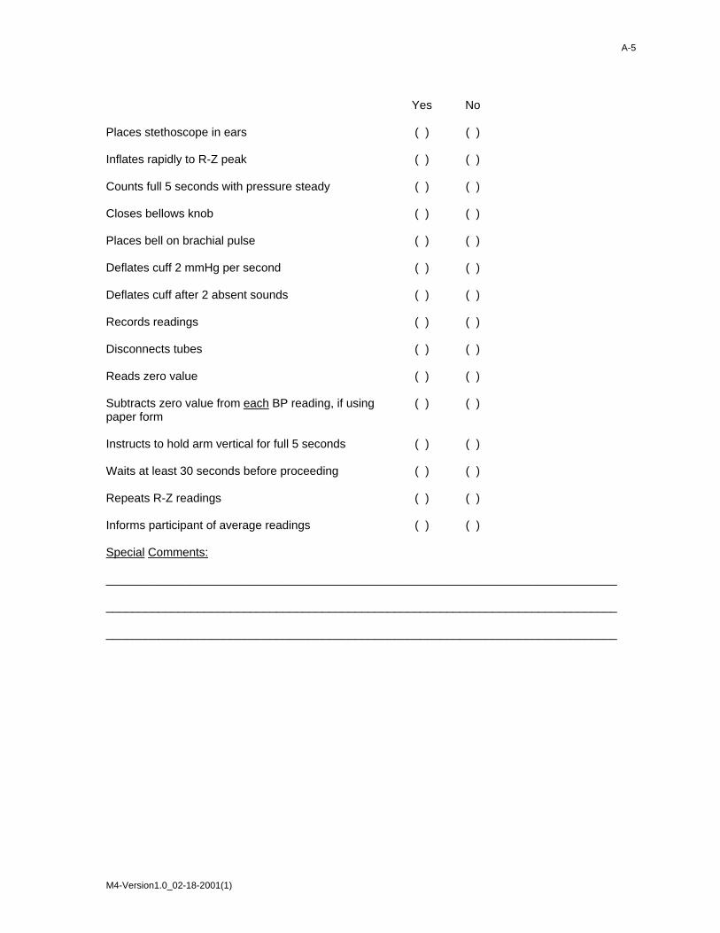
A-5
Yes No Places stethoscope in ears ( ) ( ) Inflates rapidly to R-Z peak ( ) ( ) Counts full 5 seconds with pressure steady ( ) ( ) Closes bellows knob ( ) ( ) Places bell on brachial pulse ( ) ( ) Deflates cuff 2 mmHg per second ( ) ( ) Deflates cuff after 2 absent sounds ( ) ( ) Records readings ( ) ( ) Disconnects tubes ( ) ( ) Reads zero value ( ) ( ) Subtracts zero value from each BP reading, if using paper form
( ) ( )
Instructs to hold arm vertical for full 5 seconds ( ) ( ) Waits at least 30 seconds before proceeding ( ) ( ) Repeats R-Z readings ( ) ( ) Informs participant of average readings ( ) ( ) Special Comments: ______________________________________________________________________________ ______________________________________________________________________________ ______________________________________________________________________________
M4-Version1.0_02-18-2001(1)

A-6
Appendix 4 JHS Monthly Log for Sitting Blood Pressure Station Month________Year________ Weekly Check Procedures: Week 1 2 3 4 5 1. Random-Zero
Sphygmomanometer:
Date of Check _____ _____ _____ _____ _____ A. Check Tube for Oxide Dust _____ _____ _____ _____ _____ B. Check Cap for Tightness _____ _____ _____ _____ _____ Procedures performed only if there appear to be problems: C. If mercury bounces even though the cap appears tight, remove cap, clean of any mercury beads, and check opening at top of tube for dust Check Needed and Performed during weeks 1 2 3 4 5 (Circle number of weeks applicable) D. If tube appears "dirty" (oxidized mercury) remove cap, tip manometer to retract mercury, run pipe cleaner down, replace cap Needed and Performed during weeks 1 2 3 4 5 (Circle number of weeks applicable) E. List the problem encountered, the date, and the actions taken below:
_________________________________________________________________________ _________________________________________________________________________ _________________________________________________________________________
M4-Version1.0_02-18-2001(1)

A-7
Monthly Check Procedures: A. Accuracy Check on Random-Zero Sphygmomanometer (to be performed every 2 months):
Date last accuracy check performed: _____________ Is an accuracy check due this month? ( ) Yes ( ) No Date accuracy check performed, if due: _____________ Problems found on accuracy check? ( ) Yes ( ) No If yes, list problems found and corrective action taken: _________________________________________________________________________ _________________________________________________________________________ _________________________________________________________________________ Random Zero Sphygmomanometer Check Standard 200 170 140 100 60 Random Zero ____ ____ ____ ____ ____ Zero ____ Corrected R-Z Measure* ____ ____ ____ ____ ____ Corrected R-Z measure = [(Random-Zero) - Zero] Note that this corrected R-Z measure must be within 2 mmHg of the standard.
B. Standard sphygmomanometer check:
Date of check: ______________ A. Check cap for tightness ______ B. Check tube for oxide dust ______ C. Check that mercury is at
zero with no pressure ______ List any problems found and corrective action taken: _________________________________________________________________________ _________________________________________________________________________ _________________________________________________________________________
M4-Version1.0_02-18-2001(1)

A-8
C. Measuring tape for arm circumference worn or stretched
Tape measure has been tested as part of Anthropometry station procedures. ( ) Yes ( ) No If no, perform tape measure calibration check: Check by holding the zero mark of the tape against the ruler used to measure standing height at the 150 cm. mark. If the 30 cm. mark on the tape used for arm circumference falls outside the range 119.5 to 120.5 on the standing height ruler it should be replaced. Date of check: _____ Point on height ruler where 30 cm. on tape falls _____
M4-Version1.0_02-18-2001(1)

A-9
Appendix 5 Accuracy Check on the Random-Zero Sphygmomanometer This check should be performed every two months, using a standard manometer and an Y connector. Check that the mercury level of the standard device reads zero with no pressure in the system. If it does, it should be treated as accurate and having an adequate supply of mercury. To perform the accuracy check on the R-Z instrument, attach the two arms of the Y connector directly to the reservoirs of the R-Z and standard devices, using Latex tubing. Attach the base of the Y connector to a cuff with an Air Flo control valve and bulb. To attach the Latex tubing to the reservoirs or to a valve, it may be helpful to moisten the openings of the tubing to allow the tubing to slip onto the desired parts. Wrap the cuff around a bottle or can. First open the Air Flo valve to insure that all pressure is out of the system. Check the zero level of the standard device. Next, turn the R-Z valve to the OPEN position. Close the Air Flo valve and inflate both machines until the mercury level in the standard device is at the 250 mmHg level. After 5 seconds, close the R-Z valve. Allow the mercury in the standard manometer to drop to 200 mmHg. Record the exact levels of mercury in the RZ and standard device. Repeat the procedure at 170 mmHg, 110 mmHg, 80 mmHg and 60 mmHg. Release the air from the Air Flo valve. When the mercury in the R-Z instrument has stabilized and the standard is at zero, record the zero reading from the R-Z. Subtract this value from the R-Z readings. The results should agree with the comparable readings on the standard instrument within + 2 mmHg. If this agreement is not found at all levels, repeat the procedure. If the disagreement is constant, stop using the instrument and contact the manufacturer. Worn parts should only be changed as necessary (when there is disagreement between the R-Z and standard devices). Only those parts in the parts kit should be changed. No attempt should be made to change the rubber diaphragm or bellows. Note: These instructions are adapted from the procedures employed by the MRFIT study, described in Controlled Clinical Trials, Vol. 7, No. 3 (Supplement), September 1986.
M4-Version1.0_02-18-2001(1)

A-10
Appendix 6 Form for Recording Simultaneous Blood Pressure Observations on a Volunteer by Two Technicians
Instructions: Biannually, each technician should be part of a pair of technicians who simultaneously measure blood pressure using an Y-tube on a volunteer (not a JHS participant). Each technician should separately record his/her measurements on a standard paper JHS SBP form. The blood pressure supervisor should then transfer the results to this form and calculate the differences between the two sets of measurements. If the difference on any individual measurement is greater than 4 mmHg, or if the averages of the two readings for each technician differ by more than 3 mmHg, the supervisor should indicate the corrective action taken on this form. Any further sets of simultaneous measurements for a given pair should appear on a new form. Technician IDs: 1st ID: __________ 2nd ID:__________ Date: _______ 1st Technician 2nd Technician Difference a. Initial arm circumference (cm) ___________ ___________ ___________ b. Initial cuff size selected ___________ ___________ ___________ c. Pulse Obliteration Pressure ___________ ___________ ___________ d. First SBP ___________ ___________ ___________ e. First DBP ___________ ___________ ___________ f. First Zero Reading ___________ ___________ ___________ g. First Net SBP
Corrected for Zero
___________
___________
___________ h. First Net DBP
Corrected for Zero
___________
___________
___________ i. Second SBP ___________ ___________ ___________ j. Second DBP ___________ ___________ ___________ k. Second Zero Reading ___________ ___________ ___________ l. Second Net SBP
Corrected for Zero
___________
___________
___________ m. Second Net DBP
Corrected for Zero
___________
___________
___________ n. Average Net SBP ___________ ___________ ___________ o. Average Net DBP ___________ ___________ ___________
M4-Version1.0_02-18-2001(1)

A-11
ACTION TAKEN IF DIFFERENCES BETWEEN TECHNICIANS EXCEED LIMITS SPECIFIED: ______________________________________________________________________________ ______________________________________________________________________________ ______________________________________________________________________________ ______________________________________________________________________________ ______________________________________________________________________________
M4-Version1.0_02-18-2001(1)