J1 line - Ascon Tecnologic€¦ · J1 line c User Manual • M.I.U.J1 - 3/09.02 • Cod....
37
Two alarms indicator 1 / 8 DIN - 96 x 48 J1 line c User Manual • M.I.U.J1 - 3/09.02 • Cod. J30-478-1AJ1 IE ISO 9001 Certified Ascon Tecnologic srl viale Indipendenza 56, 27029 Vigevano (PV) Tel.: +39-0381 69 871 - Fax: +39-0381 69 8730 Sito internet: www.ascontecnologic.com Indirizzo E-Mail: [email protected]
Transcript of J1 line - Ascon Tecnologic€¦ · J1 line c User Manual • M.I.U.J1 - 3/09.02 • Cod....

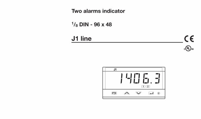
Two alarms indicator
1/8 DIN - 96 x 48
J1 line ccU s e r M a n u a l • M . I . U . J 1 - 3 / 0 9 . 0 2 • C o d . J 3 0 - 4 7 8 - 1 A J 1 I E
J1 EN-ed3 17-02-2009 15:05 Pagina 1
ISO 9001C e r t i f i e d
Ascon Tecnologic srlviale Indipendenza 56, 27029 Vigevano (PV)Tel.: +39-0381 69 871 - Fax: +39-0381 69 8730Sito internet: www.ascontecnologic.comIndirizzo E-Mail: [email protected]
Two alarms indicator
1/8 DIN - 96 x 48
J1 line cc
J1
1 2
1406 .3
J1 EN-ed3 17-02-2009 15:05 Pagina 1

2
Information
ccNOTES
ON ELECTRIC
SAFETY AND
ELECTROMAGNETIC
COMPATIBILITY
Please, read these instructions carefully before proceeding with the installation of thecontroller.Class II instrument, rearl panel mounting.
This indicator has been designed in compliance with:Regulations on electrical apparatus (appliance, systems and installations) according tothe European Community directive 73/23/EEC amended by the European Community direc-tive 93/68/EEC and the Regulations on the essential protection requirements in electricalapparatus EN61010-1: 93 + A2:95.
Regulations on Electromagnetic Compatibility according to the European Communitydirective #89/336/EEC, amended by the European Community directive #92/31/EEC,93/68/EEC, 98/13/EEC and the following regulations:Regulations on RF emissions
EN61000-6-3: 2001 residential environmentsEN61000-6-4: 2001 industrial environments
Regulation on RF immunity EN61000-6-2: 2001 industrial equipment and system
It is important to understand that it’s the responsibility of the installer to ensure compliancewith the regulations on safety requirements and EMC.The device has no user serviceable parts and requires special equipment and specialisedengineers. Therefore, a repair cannot be carried out directly by the user. For service or repair,contact the manufacturer or your sales represenattive.
All the information and warnings about safety and electromagnetic compatibility aremarked with the B sign, at the side of the note.
J1 EN-ed3 17-02-2009 15:05 Pagina 2

3
Main universal input
Resources
IN
Modbus RS485ParameterisationSupervision (option)
J11212
NO/NCNO/NC
Special functions
OP1
OP2
Alarms
Operating mode
OP1 OP2
Table of contents
TABLE OF CONTENTS
1 INSTALLATION ...................................................Page 42 ELECTRICAL CONNECTIONS .............Page 83 PRODUCT CODING ......................................Page 144 OPERATIONS ......................................................Page 185 DISPLAYS ...............................................................Page 286 COMMANDS ........................................................Page 297 TECHNICAL SPECIFICATIONS ...........Page 31
option
J1 EN-ed3 17-02-2009 15:05 Pagina 3

4
1- Installation
1 INSTALLATION
Installation must only be carried out byqualified personnel.
Before proceeding with the installation of thisindicator follow the instructions illustrated inthis manual with particular attention to theinstallation precautions marked with theB symbol, related to the EuropeanCommunity directive on electrical protectionand electromagnetic compatibility.
BTo prevent hands or metal touching partsthat may be electrically live, the indicatorsmust be installed in an enclosure.
IP 20 Terminal blockEN61010 - 1(IEC1010 - 1)
Product code label
Sealing front panel gasket
Mounting clamps
Front panelIP65 protectionEN 650529 (IEC 529)
Panelsurface
1.1 GENERAL DESCRIPTION
J1 EN-ed3 17-02-2009 15:05 Pagina 4

5
1- Installation
1.2 DIMENSIONAL DETAILS 1.3 PANEL CUT-OUT
48 mm1.89 in
110 mm4.33 in
10 mm max.0.39 in max.
96 mm3.78 in
10 mm max.0.39 in max.
45+0.6mm1.78+0.023in
65mm min.2.56 in min.
92+0.8 mm3.62+0.031 in
113 mm min.4.45 in min.
J1 EN-ed3 17-02-2009 15:05 Pagina 5

6
1 - Installation
Operating conditions
M Altitude up to 2000 m
T Temperature 0…50°C [1]
%Rh Relative humidity 5…95 % non-condensing
1.4 ENVIRONMENTAL CONDITIONS B
Special conditions
M Altitude > 2000 m
T Temperature >50°C
%Rh Humidity > 95 %
PConducting atmosphere
Use filter
Warm up
Use forced air ventilation
Use 24Vac supply version
Suggestions
Forbidden Conditions D
C Corrosive atmosphere
E Explosive atmosphereUL note[1] Operating surrounding temperature
0…50°C
J1 EN-ed3 17-02-2009 15:05 Pagina 6

7
1
3
2
2
1
2
1
12
1.5.1 INSERTTHE INSTRUMENT
1 Prepare panel cut-out2 Check-front panel gasket
position3 Insert the instrument through
the cut-out
1.5.2 INSTALLATION SECURING
1 Fit the mounting clamps asshown
2 Push the mounting clampstowards the panel surface tosecure the instrument
1.5.3 CLAMPS REMOVING
1 Insert the screwdriver in theclips of the clamps
2 Rotate the screwdriver
1.5.4 INSTRUMENTUNPLUGGING B
1 Push and 2 Pull forward to remove the
instrument
1.5 PANEL MOUNTING [1]
UL note[1] For Use on a Flat Surface of a Type 2 and Type 3 ‘raintight’ Enclosure.
Electrostatic discharges candamage the instrumentBefore removingthe instrument the operator mustdischarge himselfto ground
1MΩ
1
1
2
1- Installation
J1 EN-ed3 17-02-2009 15:05 Pagina 7

2 ELECTRICAL CONNECTIONS
2827 30292625 31 32
10 11 12
36
1 2 3
0,5Nm
Rearterminal
cover
Wire size1 mm2 (18 AWGSolid/Stranded) [2]
5.7 mm0.22 in
8
Ø
L
15 screw terminals M3
Option terminals
Tightening torque 0.5 Nm
Phillips screw-driver PH1
Flat blade screw-driver 0.8 x 4 mm
Terminals
Pin connectorq 1.4 mm 0.055 in max.
Fork-shape AMP 165004Ø 5.5 mm - 0.21 in
Stripped wireL 5.5 mm - 0.21 in
2.1 TERMINAL BLOCK [1] B
2 - Electrical connections
N
L
RS48
5
1
2
3
4
5
6
7
8
9
10
11
12
19
20
23
24
25
26
27
28
29
30
31
32
33
34
35
36TCmV
NC
C
NO
OP1
NO
COP2
C
24V—OUT
A
b
B
RTD
13
14
15
16
17
18
21
22
N/C
N/C
N/C
N/C
N/C
N/C
N/C
N/C
N/C
N/C
N/C
N/C
N/C
N/C
N/C
N/C
N/C
N/C
N/C
N/C
N/C
UL notes[1] Use 60/70 °C copper (Cu) conductor only.[2] Wire size 1 mm2 (18 AWG Solid/Stranded)
J1 EN-ed3 17-02-2009 15:05 Pagina 8

2827 30292625 31 32 33
10 11 121 2 3
0,5Nm
2827 30292625 31 32 33
10 11 12
36
1 2 3
0,5Nm
36
A B
D C
A B
D C
9
2 - Electrical connections
PRECAUTIONS BDespite the fact that the instru-ment has been designed to workin a harsh and noisy environment(level IV of the industrial standardIEC 801-4), it is recommendedthese following suggestions.
AAll the wiring must comply withthe local regulations. The supply wiring should be rout-ed away from the power cables.Avoid using electromagnetic con-tactors, power Relays and highpower motors nearby.Avoid power units nearby, espe-cially if controlled in phase anglemode.
Keep the low level sensor inputwires away from the power linesand the output wires.If this is not feasible, use shield-ed cables on the sensor input,with the shield connected toground.
2.2 SUGGESTED WIRE ROUTING B
Conduit for low level sensor cables
A = SupplyB = OutputsC = Analogue inputsD = Serial Communications
Conduit for supply and output cables
J1 EN-ed3 17-02-2009 15:05 Pagina 9

10
Powersupplyswitch
RS485
C
V ~
[3]
[6]
[6]
[5]
[5]
[5]
OP1
OP2
PTC
Alarm
Supervision
12
11
10
3
2
1
32
31
30
29
28
27
26
25
A
b
B
IN1PT100
2 - Electrical connections
2.3 EXAMPLE OF WIRING DIAGRAM B
Notes:1] Make sure that the power supply voltage is
the same as indicated on the instrument.2] Switch on the power supply only after all
the electrical connections have been com-pleted.
3] In accordance with safety regulations, installa circuit breaker on the instrument powersupply line that is clearly identified with thatinstrument (or group of instruments). Thebreaker shall be easily accessible by theoperator.
4] The instrument is PTC protected. In caseof failure it is suggested to return the instru-ment to the manufacturer for repair.
5] To protect the instrument internal circuitsuse:- 2 AT fuse for Relay outputs (220 Vac);- 4 AT fuse for Relay outputs (110 Vac).
6] Relay contacts are already protected withvaristors.Only in case of 24 Vac inductive loads,use model A51-065-30D7 varistors (onrequest)
J1 EN-ed3 17-02-2009 15:05 Pagina 10

11
2 - Electrical connections
Wire resistance 150Ω max.
For 3 wires only.Maximum line resistance: 20Ω/line
Use wires of the samelength and 1.5 mm2
size.Maximum line resistance: 20Ω/line
10
11
12
A
B
A
R2
R1
10
11
12
A
b
B
11
12
2.3.1 POWER SUPPLY B
Switching power supply with mul-tiple isolation and internal PTC • Standard version:
nominal voltage:100...240Vac (-15...+10%)Frequency 50/60Hz
• Low Voltage version:Nominal voltage: 24Vac (-25...+12%)Frequency 50/60Hz or 24Vdc (-15...+25%)
For better protection againstelectrical interference, it is rec-ommended not to connect theground clamp provided for civil-ian installations.
2.3.2 MAIN UNIVERSAL INPUT B
A L-J-K-S-R-T-B-N-E-W thermocouple type• Connect the wires with the polarity as shown;• Always use compensation cable of the correct type
for the thermocouple used;• The shield, if present, must be connected to a prop-
er ground.
B For Pt100 resistance thermometer• If a 3 wire system is used, always use cables of the
same diameter (1mm2 min.) (line 20 Ω/lead maximumresistance);
• When using a 2 wires system, always use cables of thesame size (1,5mm2 min.) and put a jumper between ter-minals 11 and 12.
C For ∆T (2x RTD Pt100) SpecialAWhen the distance between the indicator and the
sensor is 15 m using a cable of 1.5 mm2 size pro-duces an error on the measure of 1°C (1°F).
R1 + R2 must be <320Ω
L
N
25
26
Included PTC
Supply
27
J1 EN-ed3 17-02-2009 15:05 Pagina 11

12
2 - Electrical connections
Note:[1] Auxiliary power supply for external tran-
smitter 24Vdc ±20% /30mA max. withno short circuit protection
D2 With 3 wire transmitter
Rj >10MΩ.D1 With 2 wire transmitter
D For mA, mV 2.3.3 OP1 - OP2 B
OP1 SPDT relay output
OP2 SPST-NO relay output
Externalshunt 2.5Ω
Transducer24Vdc
4…20mA36
11
12
[1]mA
24Vdc
Externalshunt 2.5Ω
Transmitter
4…20mA
PV 36
11
12
[1]mA
2.3.4 ALARM OUTPUTS B
OP1 output
OP2 outputFuse
Load31
32[1]
Fuse
Load28
29[1]
30[1] Load
Vac
Fuse
NC
C
NO
Vac
Notes:[1] Varistor for inductive load 24Vac only.
Externalshunt 2.5Ω
mV mA11
12
OP1 relay output:• SPDT relay,
2A/250Vac for resistive load, fuse 2AT at250Vac, (4A/120Vac, fuse 4AT at 120Vac).
OP2 relay output:• SPST N.O. relay,
2A/250Vac for resistive load, fuse 2AT at250Vac, (4A/120Vac, fuse 4AT at 120Vac).
J1 EN-ed3 17-02-2009 15:05 Pagina 12

13
2 - Electrical connections
2.3.5 SERIAL COMMUNICATIONS (OPTION) B
C
1
2
3
1 2 3 4ON
• Galvanic isolation 500Vac/1 min.• Compliance to the EIA RS485 standard
for Modbus/Jbus• Setting dip switches
A Please, read:“gammadue® and deltadue® indica-tor series serial communication and con-figuration software” technical manual
J1 EN-ed3 17-02-2009 15:05 Pagina 13
14
3 - Product coding
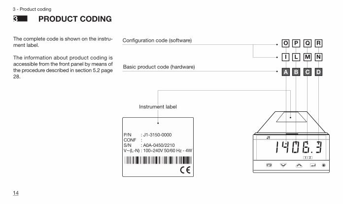
3 PRODUCT CODING
The complete code is shown on the instru-ment label.
The information about product coding isaccessible from the front panel by means ofthe procedure described in section 5.2 page28.
P/N : J1-3150-0000CONF :S/N : A0A-0450/2210V~(L-N) : 100÷240V 50/60 Hz - 4W
B C D
J1
1 2
1406 .3
L M NI
P Q RO
Basic product code (hardware)
Configuration code (software)
Instrument label
J1 EN-ed3 17-02-2009 15:05 Pagina 14
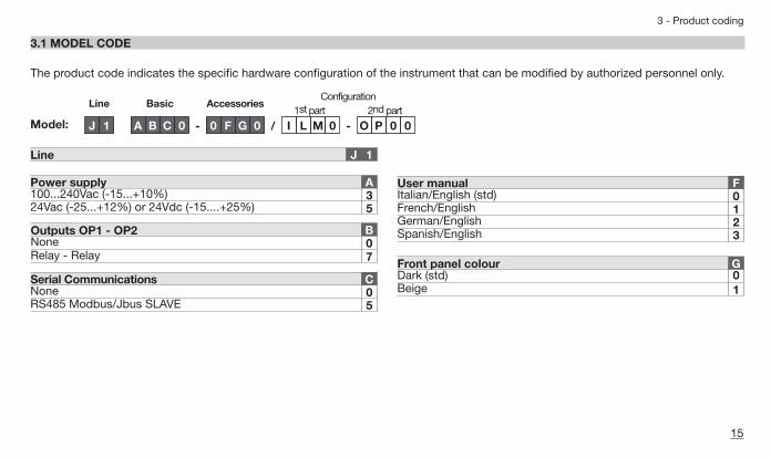
Relay - Relay 70
15
3 - Product coding
3.1 MODEL CODE
Line Basic AccessoriesConfiguration
1st part 2nd part
J 1 A B C 0 - 0 F G 0 / I L M 0Model:
Line 1J
Power supply A100...240Vac (-15...+10%) 324Vac (-25...+12%) or 24Vdc (-15....+25%) 5
The product code indicates the specific hardware configuration of the instrument that can be modified by authorized personnel only.
User manual FItalian/English (std) 0French/English 1German/English 2Spanish/English 3
Front panel colour GDark (std) 0Beige 1
O P 0 0-
RS485 Modbus/Jbus SLAVE 5
Serial Communications CNone 0
Outputs OP1 - OP2 BNone
J1 EN-ed3 17-02-2009 15:05 Pagina 15

16
3 - Product coding
A
If, when the indicator is pow-ered up for the first time, thedisplay shows the followingmessage
it means that the indicator hasnot yet been configured.
The indicator remains in stand-by until the configuration code isset correctly (pag. 24).
ConfJ1
1 2
3.2 CONFIGURATION CODING
A 4+4 index code follows themodel of the indicator.The code has to be set to con-figure the indicator(see chapter 3.1 page 15)
E.g. Enter the code 0320 to choose:- T/C type J input with range
0...600°C;- Change the display color to red
when an alarm is active.
E.g. Enter the code 2300 to choose:- AL1 absolute, active high;- AL2 absolute, active low.
Index
1st part of configuration
code
I L M N
0320
Index
2nd partof configuration
code
O P Q R
2300
TC T Cu-CuNi 0TC K Chromel-Alumel IEC584 0TC S Pt10%Rh-Pt IEC584 0
Input type and range I
Dc input 0…50mV linear
TR Pt100 IEC751 0
1Dc input 10…50mV linear 1Custom input and range [1]
TR Pt100 IEC751 0
1
TC L Fe-Const DIN43710 0
-328…752 °FTC J Fe-Cu45% Ni IEC584 0
32…2192 °F32…2912 °F
-99.9…572.0 °F-328…1112 °F32…1112 °F32…1112 °F
-200 …400 °C0…1200 °C0…1600 °C
Engineering and units
-99.9…300.0 °C
Engineering and units
-200…600 °C0…600 °C0…600 °C
654
6543210L
TC R Pt13%Rh-Pt IEC584 032…2912 °F0…1600 °C 7TC B Pt30%RhPt6%Rh IEC584 032…3272 °F0…1800 °C 8
TC N Nicrhosil-Nisil IEC584 032…2192 °F0…1200 °C 9TC E Ni10%Cr-CuNi IEC584 132…1112 °F0…600 °C 0
TC W3%Re-W25%Re 132…3632 °F0…2000 °C 2TC W5%Re-W26%Re 132…3632 °F0…2000 °C 3
TC NI-NiMo18% 132…2012 °F0…1100 °C 1
[1] For instance, other thermocouples types, ∆T (with 2 PT 100),custom linearisation etc.
J1 EN-ed3 17-02-2009 15:05 Pagina 16
17
3 - Product coding
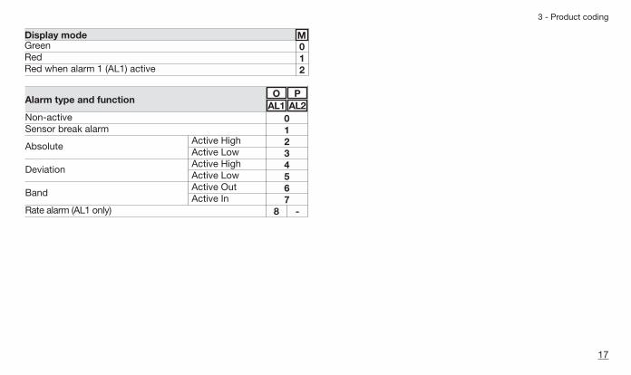
Display modeGreen 0Red 1Red when alarm 1 (AL1) active 2
M
Deviation
Band
Alarm type and function
Non-activeSensor break alarm
Absolute
6543210
7Rate alarm (AL1 only)
Active HighActive LowActive Out
Active HighActive Low
Active In8 -
OAL1
PAL2
J1 EN-ed3 17-02-2009 15:05 Pagina 17

18
4 - Operation
J1
1 2
8.8.8.8.81.4.0.6.3Over range Under range
Alarm acknowledge
Entry key for selection and value setting confirmation
Menu access
Min and Max. values display
Alarm status LEDs (reds)
Å AL1 ONÇ AL2 ON
88888_____ 88888
Input value [1] In engineering uits
-----
Note:[1] The colour of the dislplay is set through field m of the
Configuration Code (page 17).
4.1.1 KEY FUNCTIONS AND DISPLAY IN OPERATOR MODE4 OPERATIONS
J1 EN-ed3 17-02-2009 15:05 Pagina 18

19
4 - Operations
4.1.2 KEY FUNCTIONS AND DISPLAY IN PROGRAMMING MODE
A
The parameter setting procedurehas a timeout. If no keys arepressed for, at least 30 seconds,the indicator switches back, auto-matically, to the operator mode.
After having selected the para-meter or the code, press $and % to display or modifythe value (see page 20).
The value is entered when thenext parameter is selected, bypressing the R key.
Until the $ or % arepressed or if you wait for 30 sec-onds, the parameter value is notinserted.
Pressing the í key, the nextgroup of parameters is presentedon the display.
8.8.8.8 .8J1
1 2
Parameter Code/Value
Back to previous parameter
Entry key for selection and value setting confirmationValue modification
Access to the menu for:Parameter settingConfiguration
J1 EN-ed3 17-02-2009 15:05 Pagina 19

20
4 - Operations
4.2.1 NUMERIC ENTRY(i.e. how to the modify a thresh-old value from 275.0 to 240.0 )
Pressing $ or %momen-tarily changes the value by 1 unitevery push.Continued pressing of $ or% changes the value, at arate that doubles every second.Releasing the button decreasesthe rate of change.In any case value stops chang-ing the max./min. value hasreached limit set for the para-meter.
4.2.2 MNEMONIC CODES SETTING(e.g. configuration see page 30)
4.2 PARAMETER SETTING
274.8
AL. sp
AL.1sp
277.0
276.0
277.0
none
ph
Unit
°C
°f
°C
°fEngineering Units
Degree Centigrade
Degree Fahrenheit
Degree Centigrade
Degree Fahrenheit
No unit defined
Ph
Access the alarmthreshold menu
Select the AL 1threshold
Threshold valueof AL1 alarm
Threshold entryPress the è keyto store the newvalue in the instru-ment
Operator mode Displays the valueof the selected input
————Decrease
————Increase
Press the $ or % to display the next or previous mnemonicfor the selected parameter. Continued pressing of $ or % will display further mnemonics ata rate of one mnemonic every 0.5 s. The mnemonic displayed at the timethe next parameter is selected is the one stored in the parameter.
J1 EN-ed3 17-02-2009 15:05 Pagina 20

21
4 - Operations
4.3 PARAMETERISATION - MAIN MENU
1274.8
pASS
5000
Al. SP
OK
Al.par
Conf
Alarm set [1](page 21)
Alarm parametersetting [1](pag. 22)
Instrument configuration(page 22)
Operator mode
Back to theoperatormode
NO YES
4.3.1 ALARM SET
AL sp
AL.1sp
AL.1hy
AL.2sp
AL.2hy
AL.ref
é 0
é 0.5
é 0
é 0.5
é 0
Alarm threshold menu
AL1 alarm threshold
AL1 hysteresis
AL2 alarmthreshold
AL2 hysteresis
Alarm internal reference value (engineering unit)
Back to AL.1SP
Back to theoperator mode
Must be equal tothe value of the
parameterCode
Password Entry
Only if Codevalue ≥5000
Direct access tothe parameter
(only if Code<5000)
Note:[1] The menu apears only if at least one of the alarms has been con-
figured (except for the sensor break alarm).
J1 EN-ed3 17-02-2009 15:05 Pagina 21

22
4 - Operations
4.3.3 ALARMS PARAMETERISATION MENU
é OP1
é OP2
é dir
é 0
é 0
Al.Par
AL.1OP
AL.2OP
OP.1a
AL.1lb
AL.2lb
é dir
OP.2a
Alarms parameterisation menu
AL1 alarm outputnone/OpI/Op2/Op3/Op4
AL2 alarm outputnone/OpI/Op2/Op3/Op4
AL1 alarm actiondir/reU
AL2 alarm actiondir/reUAL1 alarmLatching/Blockingnone/ltch/bloc/ltbl
AL2 alarmLatching/Blocking[1]none/ltch/bloc/ltbl
Back to AL.1Sr
Note:[1] Only those alarms that are configured different than zero are shown
during the parameterisation phase (fields op page 17).
PASS
Unit
Conf
énone
OK
Con1
Con2
4.3.5 CONFIGURATION MENU
No
Yes
Entering digitsI - L - M - N of the configuration code(chapter 3.2 pages 15,16)
Entering digitsO - P of the configuration code(chapter 3.2 pages 15,16)
Engineering units(see table 2)
Back to theoperatormenu
Configurationmenu
When an unconfigured indicator is powered up for the first time, thedisplay shows:
See chapters 3, 3.1 and 3.2 starting from page 14.
Conf
Must be equal to the value of the
parameterCode
Password Entry
J1 EN-ed3 17-02-2009 15:05 Pagina 22

23
4 - Operations
in.1sh
é 0
é10000
é 0
é 0
é 0
é 0
é 0 éj:bus
é9600
é 33
é 1
in.1dd
in.1lo
in.1Hi
in.1Cn
Cut1
t.fil1 Prot
baud
Addr
Code
Filter time constantOFF/1...30s
Input shiftOFF/-60...60 digit
N° of decimals0…3
IN1 Low range=9999…32000(min. 100 digit)
IN1 High range =9999…32000(min. 100 digit)
Square rootinput IN1none/ sqrt
Cut off IN1 squareroot value [1]0…9.999(engineering units)
CommunicationsprotocolM.buS / jbuS
Baud rate1200/24004800/9600
Serial comms address1...247
Password 0…9999
factory default 33
Back to the Con.1 parameter
Value Description°C Centigrade degrees°f Fahrenheit degrees
none nonemU mVU VoltmA mA
Note:[1] Cut off the sqare root of the
input value enables the userto round to zero a result thatis too low to be meaningful.
LINEAR SCALEONLY
SERIAL COM.OPTION
(if installed)
A Amperebar BarpsIrh Rhph pH
PSI
Table 1 - Engineering unitséunit
J1 EN-ed3 17-02-2009 15:05 Pagina 23

4.4.1 ALARM THRESHOLD MENU
24
4 - Operations
For ease of operation of the indi-cator parameters have beenorganised in groups (menu),according to their functionalityarea.
OP1 and OP2 outputs can beused as alarmsit is possible to configure up to2 alarms: AL1 and AL2 (page 22)selecting for each of them:
- the type and the operating con-dition of the alarm (page 26);
- the functionality of the alarmacknowledgement (latching)#ltch (page 25);
- the blocking function is activa-ted on start up #bloc (page 25);
- Sensor break function (page 26);- Rate alarm (AL1 only)
(page 26).
AL1 alarm thresholdAL2 alarm threshold
Parameters to set the thresholdof AL1 and AL2 alarms.
The range of the alarm thresholdcorresponds to the whole span.
When the alarm occurs, the dis-play will show the red LEDsÅand Ç respectively ON and,when configured, with a changeof the display colour (AL1 only).
#Al.2sP#Al.1sP
4.4 PARAMETERS DESCRIPTION
AL1 alarm hysteresisAL1 alarm hysteresis
Hysteresis of the threshold of AL1and AL2 alarms. It is specified asa % of the full scale.
#Al.2hy#Al.Ihy
J1 EN-ed3 17-02-2009 15:05 Pagina 24
25
4 - Operations
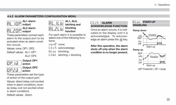
4.4.2 ALARM PARAMETERS CONFIGURATION MENU
AL1 alarmoutputAL2 alarmoutput
These parameters connect eachalarm to the output port to beactivated when an alarm condi-tion occurs.Values: none, OP1, OP2.Default values: AL1: OP1
AL2: OP2.
Output OP1actionOutput OP2action
These parameters set the typeof action of the output port.Values: direct (relay-coil excitedwhen in alarm condition), rever-se (relay-coil not excited whenin alarm condition).Default values: direct.
#Op.2a#Op.1a
#AL.2Op#AL.1Op
AL1, AL2,latching andblocking function
For each alarm it is possible toselect one of the following func-tions:none none;Ltch acknowledge;bloc blocking;Lt.bL latching + blocking
#Ltch ALARM ACKNOWLEDGE FUNCTIONOnce an alarm occurs, it is indi-cated on the display until it isacknowledged. To acknowl-edge an alarm press the key.
After this operation, the alarmshuts off only when the alarmcondition is no longer present.
#Al.2lb#Al.1lb #bloc START-UP
DISABLING
∆AL
Ramp down
Ramp up
∆SP Threshold = SP ± range
DisableREF∆AL
OnOff
Start-up
Disable
REF
OnOff
Start-up
J1 EN-ed3 17-02-2009 15:05 Pagina 25

26
4 - Operations
1st part of theconfigurationcode
Fields i and l allow theselection of type and range of theprimary input (IN1 page 16).
Field m allows the selection ofthe function mode of the display(page 17).
2nd part of theconfigurationcode
Fields oand pselect alarmtype and function (page 17).
SENSOR BREAK ALARMFUNCTIONDuring the configuration phase(page 17) set fileds o, p, tovalue 1. When the PV overcomesthe sensor range limits, the sen-sor break alarm intervention isimmediate. When the alarm is nolonger present, the alarm stops
#Con2
#Conf
4.4.3 CONFIGURATION MENU
OnOff
Activehigh
Activelow
hy
high rangelow rangeAlarm threshold
OnOff
OnOff
Activeout
Activein
hy
REF
full scalefull scale
hy
Alarm threshold
OnOff
OnOff
REF OnOff
Activehigh
Activelow
hy
+ high range- low rangeAlarm threshold
ABSOLUTE ALARMDuring the configuration phase(page 17) set fields o and pto value 2 (actve high) or 3 (acti-ve low).
DEVIATION ALARMDuring the configuration phase(page 17) set fields o and pto value 4 (active high) or 5 (acti-ve low).
BAND ALARMDuring the configuration phase(page 17) set fields o and pto value 5 (active in) or 6 (activeout).
AL1 RATE ALARM FUNCTIONDuring the configuration phase(page 17) set fileds o, to value8. When the changing rate of thePV connected to the alarm ishigher than the specified threshold,AL1 is actvated.
The changing rate can be setwithin the limits: 0.1... 5.0 digit/s.
The alarm wil be activated in 1second if the changin rate ishigher than 1 digit/s. At lowerrates the alarm activation timeincreases to up to 6 seconds fora limit change rate of 0.1 digit/s.
J1 EN-ed3 17-02-2009 15:05 Pagina 26

27
4 - Operations
Engineeringunits
This parameter allows the userto view the process in the desi-red engineering unit. When theinstrument senses temperatu-re, this parameter allows theconvertion between Farenheit(°F) and centigrade (°C). All theengineering units available arelisted at page 23 table 2.
LINEAR SCALE PARAMETERSThe parameters that follow are-displayed only when, during theconfiguration phase, a linearinput has been selected for IN1(fileds i and l at page 16).
#UnitIN1 Input numberof decimalsIN1 input lowrangeIN1 input highrange
These parameters allow the userto set the operating range andthe number of decimal point tobe displayed for the primary (IN1)input.
IN1 measure square root
This parameter enables the cal-culation of the square root of theIN1 measure (sqrt = enabled,none = disabled)
Cut-off squareroot result
This parameter allows the userto round to zero those resultsthat are not meaningful.Setting range: 0...9999.Default value: 0.
#CUt 1
#in1.Cn
#in.1Hi#in.1lo#in.1dd SERIAL COMMUNICATIONS
PARAMETERS (OPTIONAL)The parameters that follow aredisplayed only when the optio-nal communications board isinstalled in the instrument.
ComunicationsprotocolBaud rate
Instrumentserial address
Values:Protocol: Modbus/Jbus.Baud rate:
200/2400/4800/9600 baud.Instrument serial address:
1...247Default values:Protocol: Jbus.Baud rate: 9600 baud.Instrument serial address: 1
#Addr
#baud#prot
SAFETY PARAMETERS
Access code
This parameter allows the userto change the factory defaultpassword (Code = 33).If Code is set to 0 (zero), theaccess to the instrument isopern (no password needed).If 0 < Code ≤ 5000 only theConf menu is protected.Codes higher than 5000 (5000 ≤ Code < 10000), protectall the 2 main menus of theinstrument.
#Code
J1 EN-ed3 17-02-2009 15:05 Pagina 27
28
5 - Displays
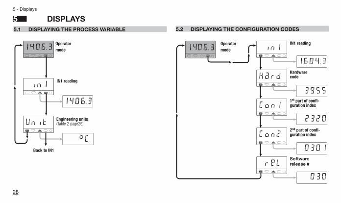
5.2 DISPLAYING THE CONFIGURATION CODES
5 DISPLAYS
1406 .3 in1
Hard
Con1
1604 .3
3955
2320
Con2
rel
0301
030
5.1 DISPLAYING THE PROCESS VARIABLE
1406 .3
in1
Unit
1406 .3
°CBack to IN1
IN1 reading
Operatormode
Operatormode
Engineering units(Table 2 page25)
IN1 reading
2nd part of confi-guration index
1st part of confi-guration index
Hardwarecode
Softwarerelease #
J1 EN-ed3 17-02-2009 15:05 Pagina 28

COMMANDS TO THE IDICATOR AND OPERATING PROCEDURE
The commands can beentered in 2 ways:
6.1 KEYPAD
see page 30
• Keypad lock• Outputs lock
6. SERIAL COMMUNICATIONS
see the manual on this topic
29
6 - Commands
6 COMMANDS
J1 EN-ed3 17-02-2009 15:05 Pagina 29

30
6 - Commands
6.1 KEYPAD COMMANDS
To lock/unlock the keypad pressand hold the keys í and èsimultaneously for 2 seconds.To confirm the keypad lock/unlockthe display flashes once.
The keypad lock/unlock can alsobe achieved over serial com-munications.
AThe keypad lock isretained in the event of power failure.
The outputs are switched to theOFF status by pressing and hold-ing the keys í and %simultaneously for 2 seconds.To confirm the output lock/unlockthe display flashes once.To unlock the outputs press thekeys simultaneously again.
The output lock/unlock can alsobe achieved over serial com-munications.
AThe output lock isretained in the event of power failure.
6.1.1 KEYPAD LOCK 6.1.2 OUTPUTS LOCK
1406.31 2
1406.31 2
Operator mode Operator mode
Press simultaneouslyfor 2 seconds
Press simultaneouslyfor 2 seconds
J1 EN-ed3 17-02-2009 15:05 Pagina 30

31
7 - Technical specification
Total configurability
IN1 Input(see pages 11,12 and 16)
Features(at 25°C environmental temp.) Description
From keypad or serial communication the user selects: input type, type/functionality and display mode of the alarms
Common characteristics
A/D converter with resolution of 50000 pointsUpdate measurement time: 0.2 secondsSampling time: 0.5 secondsInput bias: -60…+ 60 digitInput filter: 1…30 seconds (0 = disabled)
Accuracy 0.25% ±1 digits for temperature sensors0.1% ±1 digits (for mV and mA) Between 100…240Vac the error is minimal
Resistance thermometer(for ∆T: R1+R2 must be <320Ω)
Pt100Ω at 0°C(IEC 751)°C/°F selectable
2 or 3 wire connectionBurnout (with any combination)
Max. wire resistance: 20Ω max. (3 wires)Input drift: 0.35°C/10° Env. Temp.
<0.35°C/10Ω Wire Res.
DC input current(with 2.5Ω external shunt)
0… 20mA, 4... 20mARj >10MΩ
Burnout. Engineering unitsConf. decimal point positionLow range -9999… 32000High range -9999… 32000(min. range of 100 digits)
Input drift: <0.1%/20°C Env. Temp.DC input voltage 0…50mV, 10...50mV
Rj >10MΩ
7 TECHNICAL SPECIFICATIONS
OP1 output SPDT relay, 2A/250Vac (4A/120Vac) for resistive load
OP2 output SPST Relay N.O., 2A/250Vac (4A/120Vac) for resistive load
Thermocouple
L, J, T, K, S, R, B, N, E,W3, W5 (IEC 584)Rj >10MΩ,°C/°F selectable
Internal cold junction compensation with NTCError 1°C/20°C ±0.5°C Burnout
Line: 150Ω max.Input drift: <2µV/°C Env. Temp.
<5µV/10Ω Wire resistance
J1 EN-ed3 17-02-2009 15:05 Pagina 31

32
7 - Technical specification
Features(at 25°C environmental temp.) Description
AL1 - AL2 alarms
Hysteresis 0.1…10.0% c.s.
Action
Active high
Action typeDeviation threshold ±range
Changing rate threshold 0.1...5.0 digit/s
Band threshold 0…range
Absolute threshold whole range
Special functionsSensor break
Acknowledge (latching), activation inhibit (blocking), OR function
Active low
Serial comm. (option) RS485 isolated, Modbus/Jbus protocol, 1200, 2400, 4800, 9600 bit/s, 3 wiresAuxiliary Supply +24Vdc ±20% 30mA max. - for external transmitter supply
Operational Safety
Measure inputParametersAccess protection
General characteristics
Power supply(PTC protected)
Safety
UL and cUL Approvals
Electromagnetic compatibility
Protection EN60529 (IEC 529)
Parameter and configuration data are stored in a non-volatile memory for an unlimited timeDetection of out of range, short circuit or sensor break with automatic activation of the safety strategies and alerts on display
Password to access the configuration and parameter data, keypad lock, outputs lock100...240Vac (-15...+10%) 50/60 Hz or 24Vac (-25...+12%), 50/60 Hz and 24Vdc (-15...+25%)
Compliance to EN61010-1 (IEC 1010 – 1), installation class 2 (2.5kV) pollution class 2, instrument class II
Compliance to the CE standards (see page 2)
File 176452
IP65 front panel
Power consumption 4W max.
1/8 DIN - 96 x 48, depth 110 mm, weight 250 g approx.Dimensions
J1 EN-ed3 17-02-2009 15:05 Pagina 32

33
Warranty
J1 EN-ed3 17-02-2009 15:05 Pagina 33
WARRANTY
We warrant that the products willbe free from defects in material andworkmanship for 18 months fromthe date of delivery.The warranty above shall not applyfor any failure caused by the use ofthe product not in accordance withthe instructions contained in thismanual.

34
Icons table
Main universal input Digital input
Thermocouple Isolated contact
RTD (Pt100) NPN open collector
Delta Temp (2x RTD) TTL open collector
mA and mVSetpoint
Custom Local
Frequency Stand-by
Auxiliary inputKeypad lock
Current transformer Outputs lock
mA Remote setpoint Start-up function
Volt Remote setpoint Timer function
Feedback potentiometer
Memorized
Remote
Setpoint programmer
Logic
mA mV
mA
SPDT Relay
Triac
SPST Relay
Output
Setpoint slopes inhibition
PV hold
Run, Hold, Reset andprogram selection
Auto/Manual
Digital input connected functions
ICONS TABLE
J1 EN-ed3 17-02-2009 15:05 Pagina 34

35
J1 EN-ed3 17-02-2009 15:05 Pagina 35

36
J1 EN-ed3 17-02-2009 15:05 Pagina 36