J. García, F. Toral (CIEMAT) P. Fessia (CERN) November, 19 th 2014.
42
Single Aperture Orbit Corrector: Progress on MCBXFB design 4 th Joint HiLumi LHC-LARP Annual Meeting J. García, F. Toral (CIEMAT) P. Fessia (CERN) November, 19 th 2014
-
Upload
marlon-morrison -
Category
Documents
-
view
215 -
download
0
Transcript of J. García, F. Toral (CIEMAT) P. Fessia (CERN) November, 19 th 2014.
Single Aperture Orbit Corrector:
Progress on MCBXFB design
4th Joint HiLumi LHC-LARP Annual Meeting
J. García, F. Toral (CIEMAT)
P. Fessia (CERN)
November, 19th 2014

Magnet and cable specifications. Magnetic design. Protection. Mechanical design. Conclusions.
Index
2

Magnet and cable specifications
3

MCBXFB Requirements
4
MCBXFB requirements
Magnet configuration Combined dipole (Operation in X-Y square)
Minimum free aperture 150 mm
Integrated field 2.5 Tm
Baseline field for each dipole 2.1 T
Magnetic length 1.2 m
Working temperature 1.9 K
Nominal current <2500 A
Field quality(without iron saturation effect) <10 units (1e-4)
Iron geometry MQXF iron holes

Strand & Rutherford Cable
Strand parameters
Cu:Sc 1.75 -
Strand diameter 0.48 mm
Metal section 0.181 mm2
Nº of filaments 2300 -
Filament diam. 6.0 µm
I(5T,4.2K) 200-210*(prev. 203) A
Jc 2800-3300*(prev. 3085) A/mm2
Cable Parameters
No of strands 18 -
Metal area 3.257 mm2
Cable thickness 0.845 mm
Cable width 4.370 mm
Cable area 3.692 mm2
Metal fraction 0.882 -
Key-stone angle 0.67 deg
Inner Thickness 0.819 mm
Outer Thickness 0.870 mm* Extracted from strand March-14 (Data provided by Luc-Rene Oberli)
5

6
Insulation
1st option: Fibre glass sleeve◦ Easier assembly◦ Need validation test of a suitable binder: PVA under study
because ceramic binder failed at the tests carried out.
2nd option: Polyimide tape◦ Better cooling.◦ Difficult assembly.

Magnetic Design
7

Magnet configuration
8
Cosine theta: ◦ Winding and assembly procedures are well-known.◦ Long coil ends (similar to the aperture diameter).◦ High number of turns (large aperture and small cable).
Superferric: ◦ Field quality is not achievable within the available space (iron saturation
and large aperture). ◦ Very simple configuration.
Canted cosine theta:◦ Lack of experience in case of high fields.◦ Magnet protection in case of quench.◦ Large radial forces (same as cosine theta case).
◦ Azimuthal forces support and good field quality.

Inner coil (ID) & Outer Coil (OD) parameters
UnitsSingle layer
design
Double Layer design (Small
Collars)
Double Layer design (Large
Collars)
Old MCBX (Series Model,
both coils powered )
Nominal field 100% (ID) T 2.13 2.13 2.13 2.13
Nominal field 100% (OD) T 2.11 2.12 2.12 2.12
Nominal current (ID) A 2450 1250 1560 362.5x8=2900
Nominal current (OD) A 2150 1036 1340 331.25x8=2650
Coil peak field T 4.27 3.95 3.93 3.817
Working point % 60% 44.7% 48.1% 39.54%
Torque 105 Nm/m 0.92 0.98 1.19 -0.455
Conductors height (h) mm 4.37 2x4.37 2x4.37 13.2 (8)
Mean stress at the coiland collar nose interface
MPa 135 70 82 38
Aperture (ID) mm Ø150 Ø150 Ø156,2 Ø90
Aperture (OD) mm Ø180 Ø200 Ø218 Ø116.8
Iron yoke Inner Diam. mm Ø230 Ø250 Ø300 Ø180
Iron yoke Outer Diam. mm Ø540 Ø540 Ø610 Ø330
Number of conductors used (1st quad) - 162 357 324 800
9
Single layer & Double layer designs VS old MCBX (same central field comparison)

Current Magnetic Design
10
Larger collars in order to increase the stiffness of the assembly and make them self-supporting.
Saturation at nominal current for both dipoles causes the increasing of sextupoles:
◦ ∆b3= 37 units◦ ∆a3= 24 units
Possible options?- Offsetting the zero at
higher current for partial compensation.
- Iron geometry changes effectiveness to be studied.
Protection
11

CIEMAT in-house developed codebased on finite difference method :Optimistic assumptions of the model
12
Rutherford cable is modeled as a monolithic wire with the same metallic area, discarding the voids or internal volumes filled with resin.
The wedges are not modeled. Quench origin is placed at the innermost turn,
although it is not where the peak field is placed when both coils are powered.
A uniform magnetic field is assumed in the wires, equal to the peak field.
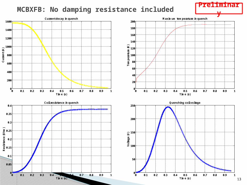
MCBXFB: No damping resistance included
13
0 0.1 0.2 0.3 0.4 0.5 0.6 0.7 0.8 0.9 10
200
400
600
800
1000
1200
1400
1600Current decay in quench
Cu
rren
t (A
)
Time (s)0 0.1 0.2 0.3 0.4 0.5 0.6 0.7 0.8 0.9 1
0
20
40
60
80
100
120
140
160
180
200Maximum temperature in quench
Tem
per
atu
re (
K)
Time (s)
0 0.1 0.2 0.3 0.4 0.5 0.6 0.7 0.8 0.9 10
0.05
0.1
0.15
0.2
0.25
0.3
0.35
0.4Coil resistance in quench
Res
ista
nce
(O
hm
)
Time (s)0 0.1 0.2 0.3 0.4 0.5 0.6 0.7 0.8 0.9 1
0
50
100
150
200
250Quenching coil voltage
Vo
ltag
e (V
)
Time (s)
Preliminary

MCBXFB: Damping resistance = 0.3 Ω (0.1 s delay)
14
0 0.1 0.2 0.3 0.4 0.5 0.6 0.7 0.8 0.90
200
400
600
800
1000
1200
1400
1600Current decay in quench
Cu
rren
t (A
)
Time (s)0 0.1 0.2 0.3 0.4 0.5 0.6 0.7 0.8 0.9
10
20
30
40
50
60
70
80
90Maximum temperature in quench
Tem
per
atu
re (
K)
Time (s)
0 0.1 0.2 0.3 0.4 0.5 0.6 0.7 0.8 0.90
0.01
0.02
0.03
0.04
0.05
0.06Coil resistance in quench
Res
ista
nce
(O
hm
)
Time (s)0 0.1 0.2 0.3 0.4 0.5 0.6 0.7 0.8 0.9
0
5
10
15
20
25
30
35Quenching coil voltage
Vo
ltag
e (V
)
Time (s)
Preliminary
No quench heaters seem to be necessary

Mechanical Design
15
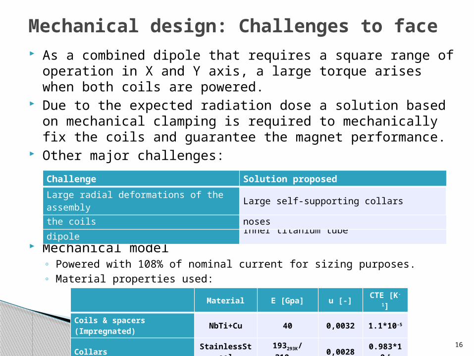
Mechanical design: Challenges to face
16
As a combined dipole that requires a square range of operation in X and Y axis, a large torque arises when both coils are powered.
Due to the expected radiation dose a solution based on mechanical clamping is required to mechanically fix the coils and guarantee the magnet performance.
Other major challenges:
Mechanical model◦ Powered with 108% of nominal current for sizing purposes.◦ Material properties used:
Material E [Gpa] u [-] CTE [K-1]
Coils & spacers (Impregnated) NbTi+Cu 40 0,0032 1.1*10-5
Collars StainlessSteel 193293K/2104.3K 0,0028 0.983*10-5
Inner tube Ti 130 0,0017 0.603*10-5
Radial inward forces at the inner dipole Inner titanium tube
Large azimuthal displacements of the coils Azimuthal interference at collar noses
Large radial deformations of the assembly Large self-supporting collars
Challenge Solution proposed

17
Mechanical model
Wedges
Iron
Ti tube
Cooling channel
Outer collar
Coil blocksInner collar

18
Mechanical model

19
Mechanical assembly
• Challenging nested assembly due to the inner dipole deformation after collaring.
• Other solutions under evaluation.

Results: Large radial collar deformations
BForcesorientation
20
Outer Collar Diam.= 275 mm
Field quality effect (Ansys2Roxie) :• ∆b3= 9 units• ∆a3= 6 units
Outer Collar Diam.= 300 mmDisplacement
scaling = 19Displacement
scaling = 19
Ellipticity ≅ 1.4 mm VS Ellipticity ≅ 0.6 mm
Currently evaluating if iron support is needed

Results: Large azimuthal coil displacements
21
Outer Collar Diam.= 275 mm Interference = 0.2 mm
Outer Collar Diam.= 300 mmInterference = 0.2 mm
The coils separates from the collar VS The coils stay attached to the collars
Azimuthal stress at outer coil edge (MPa)
Azimuthal interference value to be further evaluated
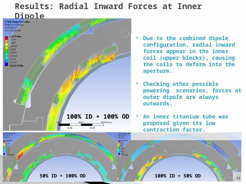
Results: Radial Inward Forces at Inner Dipole
100% ID + 100% OD
2250% ID + 100% OD 100% ID + 50% OD
Due to the combined dipole configuration, radial inward forces appear in the inner coil (upper blocks), causing the coils to deform into the aperture.
Checking other possible powering scenarios, forces at outer dipole are always outwards.
An inner titanium tube was proposed given its low contraction factor.

23
Outer Collar Diam.= 300 mmInterference= 0.2 mmFrictionless contact between coil and collar nose
Results: Radial Inward Forces at Inner Dipole
The inclusion of the titanium tube helps to decrease the inward displacement of the inner dipole coil from 0,1 mm to less than 0,02 mm.
It is intended to prevent a sudden slipping movement of the coil under Lorentz forces, because some friction is always present.
Even such a small movement, if sudden, might likely trigger a quench.
This frictionless case illustrate the worst scenario possible. If the movement were continuous, no pipe would be necessary.Tube performance
under evaluation
With Tube VS Without tube

Conclusions
24
Conclusions (I)
25
Magnetic Design:◦ Single layer and double designs were studied. Double layer design
showed as the most suitable option to meet the requirements.◦ To Be Done:
- Deal with sextupoles appeared due to iron saturation.- Persistent current and magnetization effect to be studied.
Protection◦ Preliminary results suggest that a dump resistor would be enough
to manage quench at both MCBXF models.◦ To be done: Refine the model.

Conclusions (II)
26
Mechanical design:◦ The challenges faced at this magnet were radial inwards forces at
the inner dipole, large azimuthal coil displacements and large radial deformations of the assembly.
◦ A solution based on self supporting collars and an inner titanium tube has been proposed and is currently being assessed.
◦ To be done: Evaluate if iron support is needed, inner titanium tube performance and azimuthal interference value.
Manufacturing techniques◦ To be done:
- The coils will be fully impregnated coils but a compatible binder is still needed (PVA under study).
- Challenging assembly of nested collars. Short model needed to validate the method.

Next year activities
27
March 2015: Finish magnetic and mechanical detailed design.
October 2015: First Coil fabrication.
December 2015: Short mechanical model.

Thanks for your attention
28
Annexes
29

Considerations on a MCBXFB design based on a canted cosine-theta coil configuration
30
Comparing the main challenges in the case of MCBXFB design for both designs:◦ The torque between nested dipoles:
- It will be the same for both designs.◦ The separation of the pole turn from the collar nose due to the Lorentz forces:
- It does not happen in the CCT dipole (azimuthal forces support).- In the pure cosine-theta it can be overcome with a small interference between the collar
nose and the pole turn of the coil.◦ The elliptical deformation of the support structure under Lorentz forces:
- In a CCT dipole the outer formers should hold the outwards radial forces coming from the inner layers, which complicates significantly the assembly and fabrication.
- The assembly of two nested collared coils is not easy, but seems more affordable.
The CCT configuration has not been broadly used up to now, so other open questions are:◦ The handling of the axial repulsive forces between layers.◦ The influence of the cable positioning accuracy on the field quality.◦ The training of a large and high field superconducting dipole.◦ The protection of the magnet in case of quench.◦ Formers materials to be used (insulation, stiffness and easily machining required).◦ Coils impregnation.

Inner coil (ID) & Outer Coil (OD) parameters
UnitsSingle layer
designDouble Layer design
(Small Collars)Double Layer design
(Large Collars)Old MCBX
(Series Model, both coils powered )
Nominal field 100% (ID) T 2.13 2.13 2.13 2.13
Nominal field 10% (ID) T 0.214 0.214 0.218 0.2156
Non-linearity (ID) [B100%-10∙B10%]/10∙B10%∙100] % -0.47% -0.61% -2.29% -1.2%
Nominal field 100% (OD) T 2.11 2.12 2.12 2.12
Nominal field 10% (OD) T 0.212 0.2154 0.219 0.2156
Non-linearity () [B100%-10∙B10%]/10∙B10%∙100] % -0.47% -1.58% -3.2% -1.67%
Nominal current (ID) A 2450 1250 1560 362.5x8=2900
Nominal current (OD) A 2150 1036 1340 331.25x8=2650
Coil peak field T 4.27 3.95 3.93 3.817
Working point % 60% 44.7% 48.1% 39.54%
Torque using Roxie Forces 105 Nm/m 0.92 0.98 1.19 -0.455
Torque using Analytical Equation 105 Nm/m 0.93 1.03 1.13 0.45
Difference Roxie vs Analytical Eq. % +1.68% +4.13% -4.72% -1.1%
Conductors height (h) mm 4.37 2x4.37 2x4.37 13.2 (8)
Mean radius (ID) m 0.0775 0.08 0.0825 0.0518
Mean stress at the coiland collar nose interface
MPa 135 70 82 38
Aperture (ID) mm Ø150 Ø150 Ø156,2 Ø90
Aperture (OD) mm Ø180 Ø200 Ø218 Ø116.8
Iron yoke Inner Diam. mm Ø230 Ø250 Ø300 Ø180
Iron yoke Outer Diam. mm Ø540 Ø540 Ø610 Ø330
Number of conductors used (1st quad) - 162 357 324 800
31
Single layer & Double layer designs VS old MCBX (same central field comparison)

Some useful expressions to understand where mechanical stresses come from
32
𝐼𝑇=∫− 𝜋2
𝜋2
𝐽 dl=∫− 𝜋2
𝜋2
𝐽 0 cos𝜃𝑅 dθ=2 𝐽 0𝑅 𝐽 0=𝐼 𝐼𝐶2𝑅
𝑇𝑙= �⃗�× �⃗�
𝑙=𝐵𝑂𝐶
𝑙 ∫− 𝜋2
𝜋2
𝑆 ∙ 𝐼=𝐵𝑂𝐶 ∫−𝜋2
𝜋2
2𝑅𝐼𝐶 cos𝜃 𝐽 0 cos𝜃 𝑅𝐼𝐶dθ
dl
Rθ
d=2Rcosθ
IIC-IIC
BOC
J[A/m]=J0cosθ
�⃗�
𝑻𝒍
=𝝅𝟐𝑹𝑰𝑪𝑩𝑶 𝑪 𝑰 𝑰𝑪
T
R
R
h F
F
𝝈𝜽𝒄𝒐𝒏𝒅=𝑭𝑨
=𝑻 /𝟐𝑹𝒍𝒉
=𝑻 /𝒍𝟐𝑹𝒉
𝑻𝒍
=𝝁𝟎𝝅𝟖
𝑰 𝑰𝑪 𝑰𝑶𝑪
𝑹𝑰𝑪
𝑹𝑶 𝑪 (𝑹𝒀𝟐+𝑹𝑶𝑪
𝟐
𝑹𝒀𝟐 )*
* Linear Iron
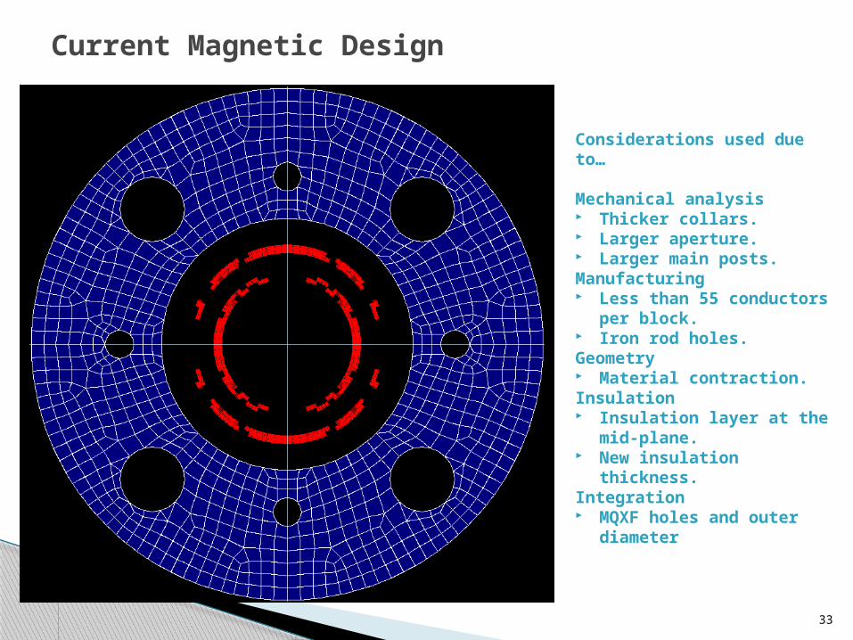
Current Magnetic Design
33
Considerations used due to…
Mechanical analysis Thicker collars. Larger aperture. Larger main posts.Manufacturing Less than 55 conductors per
block. Iron rod holes.Geometry Material contraction.Insulation Insulation layer at the mid-
plane. New insulation thickness. Integration MQXF holes and outer
diameter
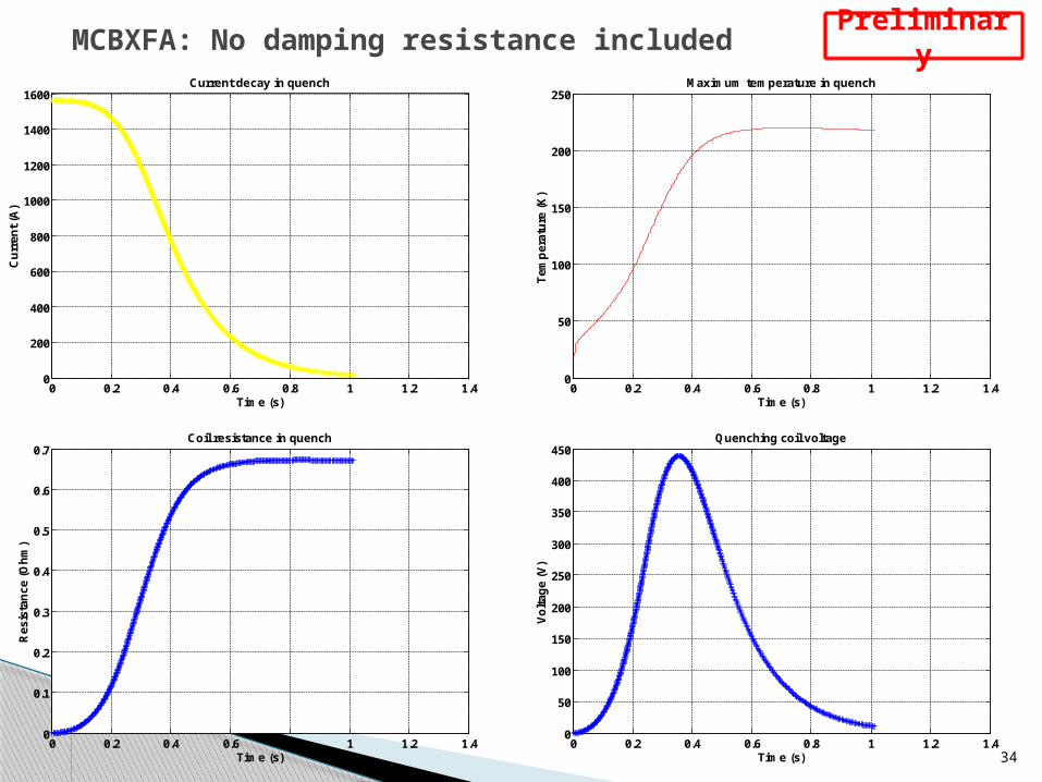
MCBXFA: No damping resistance included
34
0 0.2 0.4 0.6 0.8 1 1.2 1.40
200
400
600
800
1000
1200
1400
1600Current decay in quench
Cu
rren
t (A
)
Time (s)0 0.2 0.4 0.6 0.8 1 1.2 1.4
0
50
100
150
200
250Maximum temperature in quench
Tem
per
atu
re (
K)
Time (s)
0 0.2 0.4 0.6 0.8 1 1.2 1.40
0.1
0.2
0.3
0.4
0.5
0.6
0.7Coil resistance in quench
Res
ista
nce
(O
hm
)
Time (s)0 0.2 0.4 0.6 0.8 1 1.2 1.4
0
50
100
150
200
250
300
350
400
450Quenching coil voltage
Vo
ltag
e (V
)
Time (s)
Preliminary

MCBXFA: Damping resistance = 0.3 Ω (0.1 s delay)
35
0 0.1 0.2 0.3 0.4 0.5 0.6 0.7 0.8 0.90
200
400
600
800
1000
1200
1400
1600Current decay in quench
Cu
rren
t (A
)
Time (s)0 0.1 0.2 0.3 0.4 0.5 0.6 0.7 0.8 0.9
10
20
30
40
50
60
70
80
90Maximum temperature in quench
Tem
per
atu
re (
K)
Time (s)
0 0.1 0.2 0.3 0.4 0.5 0.6 0.7 0.8 0.90
0.005
0.01
0.015
0.02
0.025
0.03
0.035
0.04
0.045Coil resistance in quench
Res
ista
nce
(O
hm
)
Time (s)0 0.1 0.2 0.3 0.4 0.5 0.6 0.7 0.8 0.9
0
5
10
15
20
25Quenching coil voltage
Vo
ltag
e (V
)
Time (s)
Preliminary

36
Model settings and convergence challenges
2D Ansys Workbench model. 0.5-mm-thick shell elements at the collars. 1-mm-thick shell elements for the rest of the assembly.
Load steps. t=0-1: Contact offset (pre-stress). t=1-2: Assembly cooldown. t=2-3: EM forces (exported from Maxwell, 108% Nominal current).
Convergence/stability challenges No symmetry boundary conditions can be used. DOF more
difficult to constrain. Many parts involved and linked by contact. Frictional contacts
showed better performance that frictionless ones. Techniques used to achieve convergence:
Adding extra boundary conditions. Tuning up contact settings at problematic zones (Stabilization
dumping factor, Normal stiffness, ramped effects...).

37
Results: Large azimuthal coil displacementsOuter Collar Diam.= 275 mm, Interference= 0.2 mm
Azimuthal stress
Outer Coil Inner Coil

38
Results: Large azimuthal coil displacementsOuter Collar Diam.= 300 mm, Interference= 0.2 mm
Azimuthal stress
Outer Coil Inner Coil
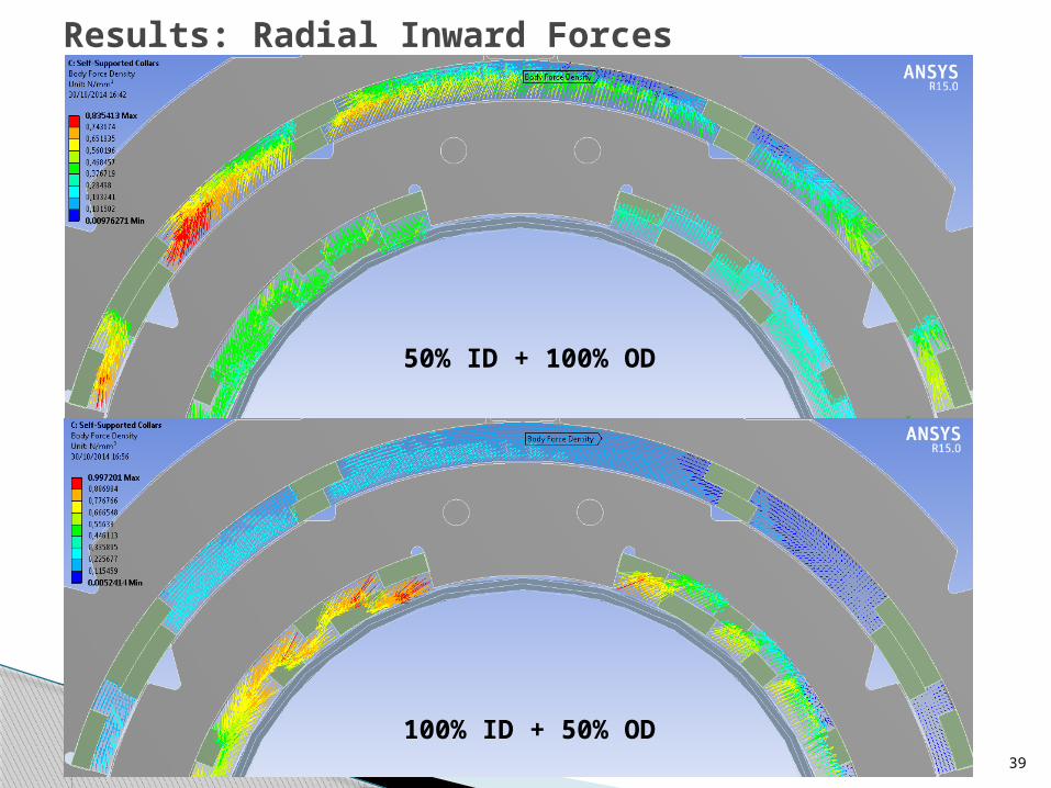
39
Results: Radial Inward Forces
100% ID + 50% OD
50% ID + 100% OD

Materials
40
Cable, wedges and inter-layer insulation: glass fibre sleeve impregnated with binder treatment as hardener (PVA to be studied).
Wedges: machined from ETP copper. End spacers: 3D printed in stainless steel. Ground insulation: Polyimide sheets Vacuum impregnated coils, radiation hard resin (cyanate-ester
blend). Collars: Machined by EDM in stainless steel. Iron: To be evaluated. Connection plate: Hard radiation resistant composite, like Ultem. End plates: Stainless steel. Inner pipe: Titanium grade 2 if grade 5 is not available.
Winding
41
Customized winding machine lent by CERN◦ New beam: 2.5 m long.◦ Electromagnetic brake.◦ Horizontal spool axis.
Winding process◦ Stainless steel mandrel protected with a polyimide sheet.◦ Binder impregnation and curation.◦ Outer layer will be wound on top of the inner one with an
intermediate glassfiber sheet for extra protection.◦ Vacuum impregnation with hard radiation resin.
Assembly
42
Collars placed around the coils with a vertical press (custom tooling required).
Layer of protection between both dipoles, likely a glass fibre sheet
Innermost turn of the coils will be protected by a stainless steel sheet from the collar nose sliding.
Iron laminations around the coil assembly.