iZook – Suzuki 4×4 Tech Information, Accessories, Travel ...
116
SUZUKI ──────────── SQ 416-420 ──────────── M.Y 1998 - 2005 SUPPLEMENTARY SERVICE MANUAL FOR CAVANS TOP MODEL
Transcript of iZook – Suzuki 4×4 Tech Information, Accessories, Travel ...
SUZUKI ──────────── SQ 416-420 ────────────
M.Y 1998 - 2005 SUPPLEMENTARY SERVICE MANUAL FOR CAVANS TOP MODEL
SQHokubei(Supple)
TRANSMISSION, CLUTCH ANDDIFFERENTIAL
Automatic Transmission
BRAKES
Brake Pipe/Hose/MasterCylinder
STEERING, SUSPENSION,WHEELS AND TIRES
Power Steering (P/S) System
Air Bag Steering Wheel andColumn
Front Suspension
Rear Suspension
Wheel and Tires
HEATING AND AIRCONDITIONING
Air Conditioning
GENERAL INFORMATION
General Information 0A
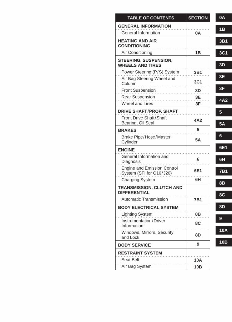
TABLE OF CONTENTS SECTION
DRIVE SHAFT/PROP. SHAFT
Front Drive Shaft /ShaftBearing, Oil Seal
ENGINE
General Information andDiagnosis
Engine and Emission ControlSystem (SFI for G16/J20)
Charging System
BODY ELECTRICAL SYSTEM
Lighting System
Instrumentation/DriverInformation
Windows, Mirrors, Securityand Lock
BODY SERVICE
RESTRAINT SYSTEM
Seat Belt
Air Bag System
1B
3B1
3C1
3D
3E
3F
4A2
5
5A
6
6E1
6H
7B1
8B
8C
8D
9
10A
10B
3D
3C1
1B
0A
3B1
3E
3F
4A2
5
5A
6
6E1
6H
7B1
8B
8C
8D
9
10A
10B

SQHokubei(Supple)
0A
GENERAL INFORMATION 0A-1
SECTION 0A
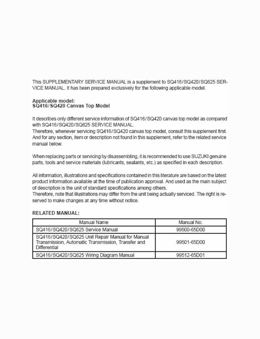
GENERAL INFORMATIONNOTE:For the descriptions (items) not found in this section, refer to the same section of the Service Manual men-tioned in FOREWORD of this manual.
CONTENTS
PRECAUTIONS 0A- 2. . . . . . . . . . . . . . . . . . . . . . . . . . . . . . . . . . . . . . . . . . . . . . . . . . . . . . . . . . . . . . . . . . . . . . . . . . . . Precautions for Vehicle Equipped with a Supplemental Restraint (Air Bag) System 0A- 2. . . . . . . . . . . . . . . .
Diagnosis 0A- 2. . . . . . . . . . . . . . . . . . . . . . . . . . . . . . . . . . . . . . . . . . . . . . . . . . . . . . . . . . . . . . . . . . . . . . . . . . . . . Servicing and Handling 0A- 3. . . . . . . . . . . . . . . . . . . . . . . . . . . . . . . . . . . . . . . . . . . . . . . . . . . . . . . . . . . . . . . . . .

SQHokubei(Supple)
1. Air bag wire harness2. Passenger air bag
(inflator) module3. SDM4. DLC
5. Contact coil6. Driver air bag (inflator)
module7. Seat belt pretensioner
(if equipped)
0A-2 GENERAL INFORMATION
PRECAUTIONS
PRECAUTION FOR VEHICLES EQUIPPEDWITH A SUPPLEMENTAL RESTRAINT(AIR BAG) SYSTEM
WARNING:� The configuration of air bag system parts are as shown in
the figure. When it is necessary to service (remove, rein-stall and inspect) these parts, be sure to follow proce-dures described in SECTION 10B. Failure to follow properprocedures could result in possible air bag system activa-tion, personal injury, damage to parts or air bag systembeing unable to activate when necessary.
� If the air bag system and another vehicle system bothneed repair, SUZUKI recommends that the air bag systembe repaired first, to help avoid unintended air bag systemactivation.
�Do not modify the steering wheel, dashboard, or any otherair bag system components. Modifications can adverselyaffect air bag system performance and lead to injury.
� If the vehicle will be exposed to temperatures over 93 �C(200�F) (for example, during a paint baking process), re-move the air bag system components beforehand to avoidcomponent damage or unintended air bag system activa-tion.
DIAGNOSIS�When troubleshooting air bag system, be sure to follow
“DIAGNOSIS” in SECTION 10B. Bypassing these proce-dures may result in extended diagnostic time, incorrect diag-nosis, and incorrect parts replacement.
�Never use electrical test equipment other than that specifiedin this manual.
WARNING:Never attempt to measure the resistance of the air bag (in-flator) modules (driver and passenger) and seat belt preten-tioners (driver and passenger). It is very dangerous as theelectric current from the tester may deploy the air bag or ac-tivate the pretensioner.
SQHokubei(Supple)
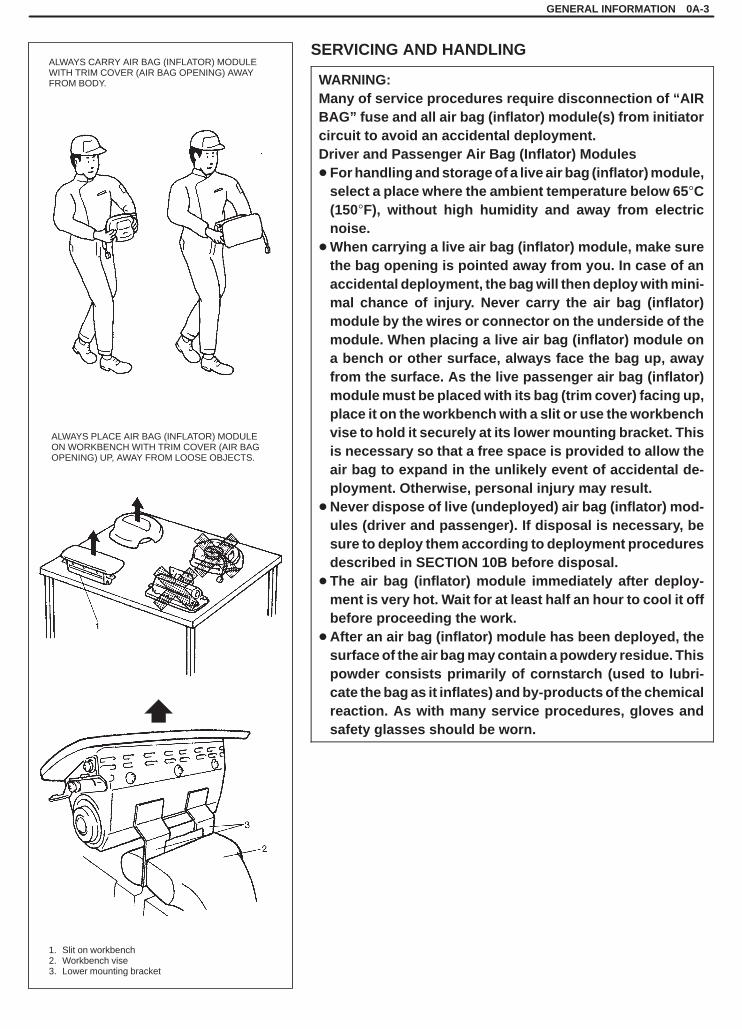
ALWAYS CARRY AIR BAG (INFLATOR) MODULEWITH TRIM COVER (AIR BAG OPENING) AWAYFROM BODY.
ALWAYS PLACE AIR BAG (INFLATOR) MODULEON WORKBENCH WITH TRIM COVER (AIR BAGOPENING) UP, AWAY FROM LOOSE OBJECTS.
1. Slit on workbench2. Workbench vise3. Lower mounting bracket
GENERAL INFORMATION 0A-3
SERVICING AND HANDLING
WARNING:Many of service procedures require disconnection of “AIRBAG” fuse and all air bag (inflator) module(s) from initiatorcircuit to avoid an accidental deployment.Driver and Passenger Air Bag (Inflator) Modules� For handling and storage of a live air bag (inflator) module,
select a place where the ambient temperature below 65 �C(150�F), without high humidity and away from electricnoise.
�When carrying a live air bag (inflator) module, make surethe bag opening is pointed away from you. In case of anaccidental deployment, the bag will then deploy with mini-mal chance of injury. Never carry the air bag (inflator)module by the wires or connector on the underside of themodule. When placing a live air bag (inflator) module ona bench or other surface, always face the bag up, awayfrom the surface. As the live passenger air bag (inflator)module must be placed with its bag (trim cover) facing up,place it on the workbench with a slit or use the workbenchvise to hold it securely at its lower mounting bracket. Thisis necessary so that a free space is provided to allow theair bag to expand in the unlikely event of accidental de-ployment. Otherwise, personal injury may result.
�Never dispose of live (undeployed) air bag (inflator) mod-ules (driver and passenger). If disposal is necessary, besure to deploy them according to deployment proceduresdescribed in SECTION 10B before disposal.
� The air bag (inflator) module immediately after deploy-ment is very hot. Wait for at least half an hour to cool it offbefore proceeding the work.
� After an air bag (inflator) module has been deployed, thesurface of the air bag may contain a powdery residue. Thispowder consists primarily of cornstarch (used to lubri-cate the bag as it inflates) and by-products of the chemicalreaction. As with many service procedures, gloves andsafety glasses should be worn.
SQHokubei(Supple)
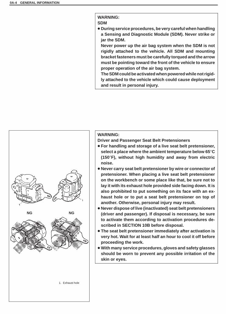
1. Exhaust hole
NGNG
0A-4 GENERAL INFORMATION
WARNING:SDM�During service procedures, be very careful when handling
a Sensing and Diagnostic Module (SDM). Never strike orjar the SDM.Never power up the air bag system when the SDM is notrigidly attached to the vehicle. All SDM and mountingbracket fasteners must be carefully torqued and the arrowmust be pointing toward the front of the vehicle to ensureproper operation of the air bag system.The SDM could be activated when powered while not rigid-ly attached to the vehicle which could cause deploymentand result in personal injury.
WARNING:Driver and Passenger Seat Belt Pretensioners� For handling and storage of a live seat belt pretensioner,
select a place where the ambient temperature below 65 �C(150�F), without high humidity and away from electricnoise.
�Never carry seat belt pretensioner by wire or connector ofpretensioner. When placing a live seat belt pretensioneron the workbench or some place like that, be sure not tolay it with its exhaust hole provided side facing down. It isalso prohibited to put something on its face with an ex-haust hole or to put a seat belt pretensioner on top ofanother. Otherwise, personal injury may result.
�Never dispose of live (inactivated) seat belt pretensioners(driver and passenger). If disposal is necessary, be sureto activate them according to activation procedures de-scribed in SECTION 10B before disposal.
� The seat belt pretensioner immediately after activation isvery hot. Wait for at least half an hour to cool it off beforeproceeding the work.
�With many service procedures, gloves and safety glassesshould be worn to prevent any possible irritation of theskin or eyes.
SQHokubei(Supple)
GENERAL INFORMATION 0A-5
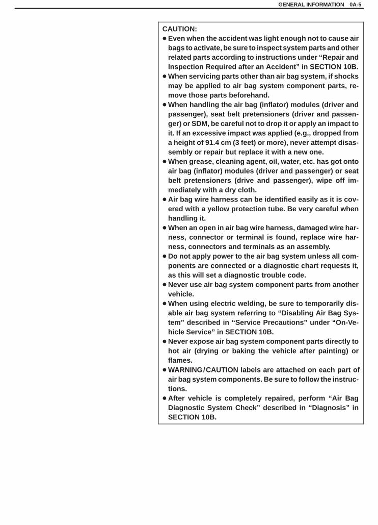
CAUTION:� Even when the accident was light enough not to cause air
bags to activate, be sure to inspect system parts and otherrelated parts according to instructions under “Repair andInspection Required after an Accident” in SECTION 10B.
�When servicing parts other than air bag system, if shocksmay be applied to air bag system component parts, re-move those parts beforehand.
�When handling the air bag (inflator) modules (driver andpassenger), seat belt pretensioners (driver and passen-ger) or SDM, be careful not to drop it or apply an impact toit. If an excessive impact was applied (e.g., dropped froma height of 91.4 cm (3 feet) or more), never attempt disas-sembly or repair but replace it with a new one.
�When grease, cleaning agent, oil, water, etc. has got ontoair bag (inflator) modules (driver and passenger) or seatbelt pretensioners (drive and passenger), wipe off im-mediately with a dry cloth.
� Air bag wire harness can be identified easily as it is cov-ered with a yellow protection tube. Be very careful whenhandling it.
�When an open in air bag wire harness, damaged wire har-ness, connector or terminal is found, replace wire har-ness, connectors and terminals as an assembly.
�Do not apply power to the air bag system unless all com-ponents are connected or a diagnostic chart requests it,as this will set a diagnostic trouble code.
�Never use air bag system component parts from anothervehicle.
�When using electric welding, be sure to temporarily dis-able air bag system referring to “Disabling Air Bag Sys-tem” described in “Service Precautions” under “On-Ve-hicle Service” in SECTION 10B.
�Never expose air bag system component parts directly tohot air (drying or baking the vehicle after painting) orflames.
�WARNING/CAUTION labels are attached on each part ofair bag system components. Be sure to follow the instruc-tions.
� After vehicle is completely repaired, perform “Air BagDiagnostic System Check” described in “Diagnosis” inSECTION 10B.
SQHokubei(Supple)
AIR CONDITIONING (OPTIONAL) 1B-1
1B
SECTION 1B
AIR CONDITIONING (OPTIONAL)WARNING:For vehicles equipped with Supplemental Restraint (Air Bag) System:� Service on and around the air bag system components or wiring must be performed only by an autho-
rized SUZUKI dealer. Refer to “Air Bag System Components and Wiring Location View” under “Gener-al Description” in air bag system section in order to confirm whether you are performing service onor near the air bag system components or wiring. Please observe all WARNINGS and “Service Precau-tions” under “On-Vehicle Service” in air bag system section before performing service on or aroundthe air bag system components or wiring. Failure to follow WARNINGS could result in unintentionalactivation of the system or could render the system inoperative. Either of these two conditions mayresult in severe injury.
� Technical service work must be started at least 90 seconds after the ignition switch is turned to the“LOCK” position and the negative cable is disconnected from the battery. Otherwise, the system maybe activated by reserve energy in the Sensing and Diagnostic Module (SDM).
CAUTION:The air conditioning system of this vehicle uses refrigerant HFC-134a (R-134a).None of refrigerant, compressor oil and component parts is interchangeable between two types of A/C:one using refrigerant CFC-12 (R-12) and the other using refrigerant HFC-134a (R-134a).Be sure to check which refrigerant is used before any service work including inspection and mainte-nance. For identification between these two types, refer to the description in page 1B-2.When replenishing or changing refrigerant and compressor oil and when replacing parts, make surethat the material or the part to be used is appropriate to the A/C installed in the vehicle being serviced.Use of incorrect one will result in leakage of refrigerant, damage in parts or other faulty condition.
NOTE:For the descriptions (items) not found in this section, refer to the same section of the Service Manual men-tioned in FOREWORD of this manual.
CONTENTS
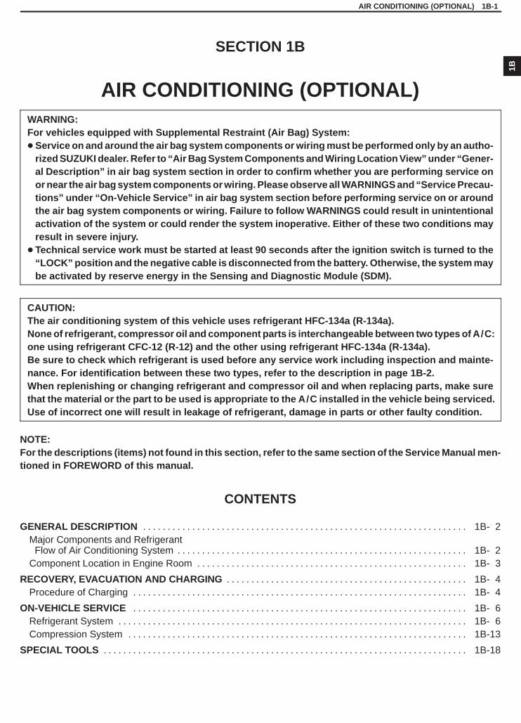
GENERAL DESCRIPTION 1B- 2. . . . . . . . . . . . . . . . . . . . . . . . . . . . . . . . . . . . . . . . . . . . . . . . . . . . . . . . . . . . . . . . . . Major Components and Refrigerant
Flow of Air Conditioning System 1B- 2. . . . . . . . . . . . . . . . . . . . . . . . . . . . . . . . . . . . . . . . . . . . . . . . . . . . . . . . . . . Component Location in Engine Room 1B- 3. . . . . . . . . . . . . . . . . . . . . . . . . . . . . . . . . . . . . . . . . . . . . . . . . . . . . . .
RECOVERY, EVACUATION AND CHARGING 1B- 4. . . . . . . . . . . . . . . . . . . . . . . . . . . . . . . . . . . . . . . . . . . . . . . . . Procedure of Charging 1B- 4. . . . . . . . . . . . . . . . . . . . . . . . . . . . . . . . . . . . . . . . . . . . . . . . . . . . . . . . . . . . . . . . . . . .
ON-VEHICLE SERVICE 1B- 6. . . . . . . . . . . . . . . . . . . . . . . . . . . . . . . . . . . . . . . . . . . . . . . . . . . . . . . . . . . . . . . . . . . . Refrigerant System 1B- 6. . . . . . . . . . . . . . . . . . . . . . . . . . . . . . . . . . . . . . . . . . . . . . . . . . . . . . . . . . . . . . . . . . . . . . . Compression System 1B-13. . . . . . . . . . . . . . . . . . . . . . . . . . . . . . . . . . . . . . . . . . . . . . . . . . . . . . . . . . . . . . . . . . . . .
SPECIAL TOOLS 1B-18. . . . . . . . . . . . . . . . . . . . . . . . . . . . . . . . . . . . . . . . . . . . . . . . . . . . . . . . . . . . . . . . . . . . . . . . . .

SQHokubei(Supple)
1. Compressor label2. Service valve
1B-2 AIR CONDITIONING (OPTIONAL)
1. Compressor2. Magnet clutch3. Condenser4. Receiver5. Dual pressure switch6. Expansion valve7. Evaporator8. Blower motor9. Heater core
10. Dryer
State of Refrigerant
Liquid
Vapor
Superheated VaporCondenserCooling air
GENERAL DESCRIPTION
Whether the A/C in the vehicle being serviced uses R-134a or R-12is indicated on LABEL on the compressor. Also, it can be checkedby the shape of the service (charge) valve.
MAJOR COMPONENTS AND REFRIGERANT FLOW OF AIR CONDITIONINGSYSTEM

SQHokubei(Supple)
G16 LH steering vehicle
1. Liquid pipe2. Compressor suction hose3. Dual pressure switch4. Condenser outlet pipe5. Condenser
6. Compressor delivery hose7. Compressor8. Suction pipe9. High pressure service valve
10. Low pressure service valveJ20 LH steering vehicle
10
9
9
10
AIR CONDITIONING (OPTIONAL) 1B-3
COMPONENT LOCATION IN ENGINE ROOM
SQHokubei(Supple)
1B-4 AIR CONDITIONING (OPTIONAL)
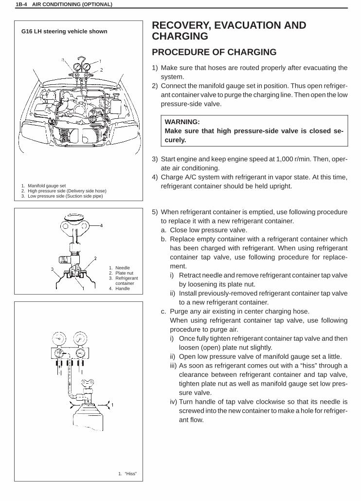
1. Manifold gauge set2. High pressure side (Delivery side hose)3. Low pressure side (Suction side pipe)
1. Needle2. Plate nut3. Refrigerant
container4. Handle
1. “Hiss”
G16 LH steering vehicle shownRECOVERY, EVACUATION ANDCHARGING
PROCEDURE OF CHARGING
1) Make sure that hoses are routed properly after evacuating thesystem.
2) Connect the manifold gauge set in position. Thus open refriger-ant container valve to purge the charging line. Then open the lowpressure-side valve.
WARNING:Make sure that high pressure-side valve is closed se-curely.
3) Start engine and keep engine speed at 1,000 r/min. Then, oper-ate air conditioning.
4) Charge A/C system with refrigerant in vapor state. At this time,refrigerant container should be held upright.
5) When refrigerant container is emptied, use following procedureto replace it with a new refrigerant container.a. Close low pressure valve.b. Replace empty container with a refrigerant container which
has been charged with refrigerant. When using refrigerantcontainer tap valve, use following procedure for replace-ment.i) Retract needle and remove refrigerant container tap valve
by loosening its plate nut.ii) Install previously-removed refrigerant container tap valve
to a new refrigerant container.c. Purge any air existing in center charging hose.
When using refrigerant container tap valve, use followingprocedure to purge air.i) Once fully tighten refrigerant container tap valve and then
loosen (open) plate nut slightly.ii) Open low pressure valve of manifold gauge set a little.iii) As soon as refrigerant comes out with a “hiss” through a
clearance between refrigerant container and tap valve,tighten plate nut as well as manifold gauge set low pres-sure valve.
iv) Turn handle of tap valve clockwise so that its needle isscrewed into the new container to make a hole for refriger-ant flow.
SQHokubei(Supple)
AIR CONDITIONING (OPTIONAL) 1B-5
6) After the system has been charged with specified amount (350– 450 g, 12.3 – 16.0 oz.) of refrigerant or when low and high pres-sure gauges have indicated specified value below respectively,close low pressure side valve of manifold gauge set.
Low pressure gauge when charged with specified amountAbout 200 – 300 kPa (2 – 3 kg/cm 2, 29 – 43 psi)
(At A/C inlet temperature 30 – 35 �C, 86 – 95�F)
High pressure gauge when charged with specified amountAbout 1370 – 1670 kPa (14 – 17 kg/cm 2, 200 – 244 psi)
(At A/C inlet temperature 30 – 35 �C, 86 – 95�F)
SQHokubei(Supple)
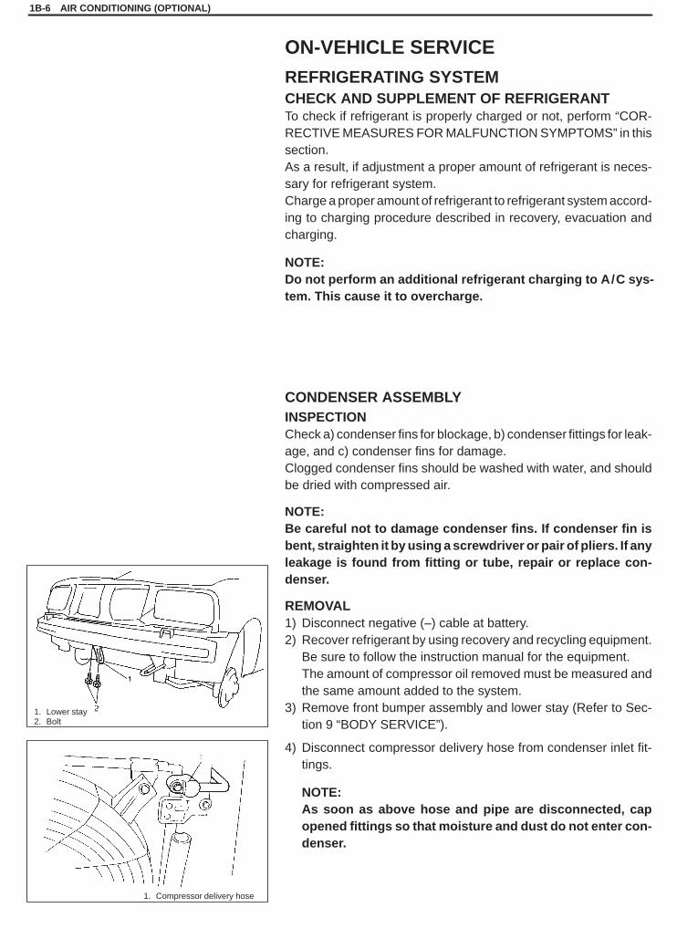
1. Compressor delivery hose
1. Lower stay2. Bolt
1B-6 AIR CONDITIONING (OPTIONAL)
ON-VEHICLE SERVICE
REFRIGERATING SYSTEMCHECK AND SUPPLEMENT OF REFRIGERANTTo check if refrigerant is properly charged or not, perform “COR-RECTIVE MEASURES FOR MALFUNCTION SYMPTOMS” in thissection.As a result, if adjustment a proper amount of refrigerant is neces-sary for refrigerant system.Charge a proper amount of refrigerant to refrigerant system accord-ing to charging procedure described in recovery, evacuation andcharging.
NOTE:Do not perform an additional refrigerant charging to A/C sys-tem. This cause it to overcharge.
CONDENSER ASSEMBLYINSPECTIONCheck a) condenser fins for blockage, b) condenser fittings for leak-age, and c) condenser fins for damage.Clogged condenser fins should be washed with water, and shouldbe dried with compressed air.
NOTE:Be careful not to damage condenser fins. If condenser fin isbent, straighten it by using a screwdriver or pair of pliers. If anyleakage is found from fitting or tube, repair or replace con-denser.
REMOVAL1) Disconnect negative (–) cable at battery.2) Recover refrigerant by using recovery and recycling equipment.
Be sure to follow the instruction manual for the equipment.The amount of compressor oil removed must be measured andthe same amount added to the system.
3) Remove front bumper assembly and lower stay (Refer to Sec-tion 9 “BODY SERVICE”).
4) Disconnect compressor delivery hose from condenser inlet fit-tings.
NOTE:As soon as above hose and pipe are disconnected, capopened fittings so that moisture and dust do not enter con-denser.
SQHokubei(Supple)
AIR CONDITIONING (OPTIONAL) 1B-7
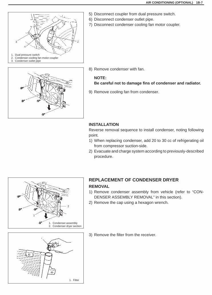
1. Dual pressure switch2. Condenser cooling fan motor coupler3. Condenser outlet pipe
3
1. Filter
1
2
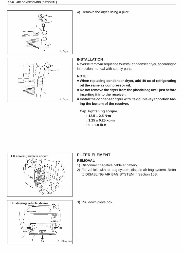
1. Condenser assembly2. Condenser dryer section
5) Disconnect coupler from dual pressure switch.6) Disconnect condenser outlet pipe.7) Disconnect condenser cooling fan motor coupler.
8) Remove condenser with fan.
NOTE:Be careful not to damage fins of condenser and radiator.
9) Remove cooling fan from condenser.
INSTALLATIONReverse removal sequence to install condenser, noting followingpoint.1) When replacing condenser, add 20 to 30 cc of refrigerating oil
from compressor suction-side.2) Evacuate and charge system according to previously-described
procedure.
REPLACEMENT OF CONDENSER DRYERREMOVAL1) Remove condenser assembly from vehicle (refer to “CON-
DENSER ASSEMBLY REMOVAL” in this section).2) Remove the cap using a hexagon wrench.
3) Remove the filter from the receiver.
SQHokubei(Supple)
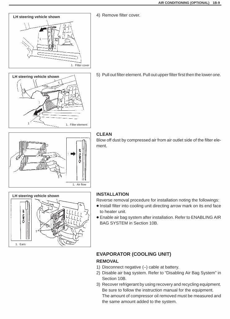
1. Dryer
1. Dryer
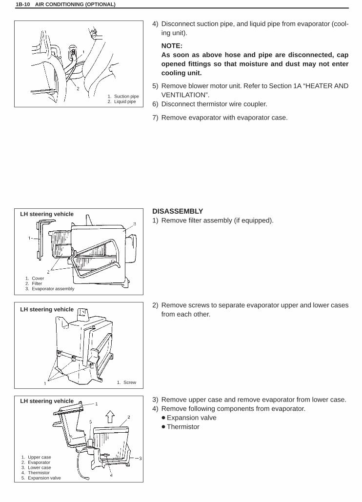
1. Glove box
LH steering vehicle shown
LH steering vehicle shown
1B-8 AIR CONDITIONING (OPTIONAL)
4) Remove the dryer using a plier.
INSTALLATIONReverse removal sequence to install condenser dryer, according toinstruction manual with supply parts.
NOTE:� When replacing condenser dryer, add 40 cc of refrigerating
oil the same as compressor oil.� Do not remove the dryer from the plastic bag until just before
inserting it into the receiver.� Install the condenser dryer with its double-layer portion fac-
ing the bottom of the receiver.
Cap Tightening Torque: 12.5 � 2.5 N.m: 1.25 � 0.25 kg-m: 9 � 1.8 lb-ft
FILTER ELEMENTREMOVAL1) Disconnect negative cable at battery.2) For vehicle with air bag system, disable air bag system. Refer
to DISABLING AIR BAG SYSTEM in Section 10B.
3) Pull down glove box.
SQHokubei(Supple)
1. Filter element
1. Filter cover
1. Air flow
1
1
1. Ears
LH steering vehicle shown
LH steering vehicle shown
LH steering vehicle shown
AIR CONDITIONING (OPTIONAL) 1B-9
4) Remove filter cover.
5) Pull out filter element. Pull out upper filter first then the lower one.
CLEANBlow off dust by compressed air from air outlet side of the filter ele-ment.
INSTALLATIONReverse removal procedure for installation noting the followings:� Install filter into cooling unit directing arrow mark on its end face
to heater unit.� Enable air bag system after installation. Refer to ENABLING AIR
BAG SYSTEM in Section 10B.
EVAPORATOR (COOLING UNIT)REMOVAL1) Disconnect negative (–) cable at battery.2) Disable air bag system. Refer to “Disabling Air Bag System” in
Section 10B.3) Recover refrigerant by using recovery and recycling equipment.
Be sure to follow the instruction manual for the equipment.The amount of compressor oil removed must be measured andthe same amount added to the system.
SQHokubei(Supple)
1. Cover2. Filter3. Evaporator assembly
1. Suction pipe2. Liquid pipe
1. Screw
1. Upper case2. Evaporator3. Lower case4. Thermistor5. Expansion valve
1
LH steering vehicle
LH steering vehicle
LH steering vehicle
1B-10 AIR CONDITIONING (OPTIONAL)
4) Disconnect suction pipe, and liquid pipe from evaporator (cool-ing unit).
NOTE:As soon as above hose and pipe are disconnected, capopened fittings so that moisture and dust may not entercooling unit.
5) Remove blower motor unit. Refer to Section 1A “HEATER ANDVENTILATION”.
6) Disconnect thermistor wire coupler.
7) Remove evaporator with evaporator case.
DISASSEMBLY1) Remove filter assembly (if equipped).
2) Remove screws to separate evaporator upper and lower casesfrom each other.
3) Remove upper case and remove evaporator from lower case.4) Remove following components from evaporator.
� Expansion valve� Thermistor
SQHokubei(Supple)
1. Suction pipe2. Liquid pipe
1. Suction hose2. Condenser outlet pipe3. Pipe clamp
AIR CONDITIONING (OPTIONAL) 1B-11
INSPECTION1) Check evaporator fins for blockage. If found clogged, use com-
pressed air to clean the fins.
NOTE:Do not use water for cleaning of evaporator.
2) Check inlet and outlet fittings for crack or scratch. Repair themas required.
ASSEMBLY AND INSTALLATION1) Reverse removal sequence to install evaporator.2) Enable air bag system. Refer to “Enabling Air Bag System” in
Section 10B.3) Evacuate and charge system according to previously described
procedure.
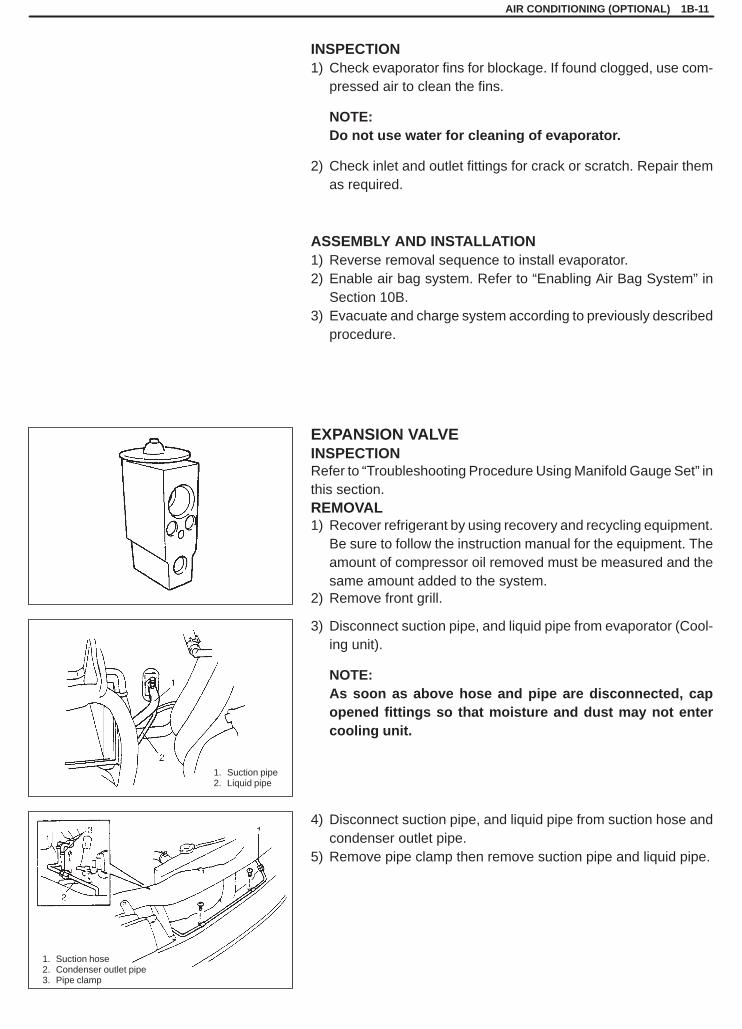
EXPANSION VALVEINSPECTIONRefer to “Troubleshooting Procedure Using Manifold Gauge Set” inthis section.REMOVAL1) Recover refrigerant by using recovery and recycling equipment.
Be sure to follow the instruction manual for the equipment. Theamount of compressor oil removed must be measured and thesame amount added to the system.
2) Remove front grill.
3) Disconnect suction pipe, and liquid pipe from evaporator (Cool-ing unit).
NOTE:As soon as above hose and pipe are disconnected, capopened fittings so that moisture and dust may not entercooling unit.
4) Disconnect suction pipe, and liquid pipe from suction hose andcondenser outlet pipe.
5) Remove pipe clamp then remove suction pipe and liquid pipe.

SQHokubei(Supple)
1. Expansion valve
1B-12 AIR CONDITIONING (OPTIONAL)
6) Remove expansion valve.
INSTALLATION1) Reverse removal sequence to install expansion valve.2) Evacuate and charge system according to previously described
procedure.

SQHokubei(Supple)
1. Manifold gauge set2. High pressure side
(Delivery side hose)3. Low pressure side
(Suction side pipe)
G16 LH steering vehicle
AIR CONDITIONING (OPTIONAL) 1B-13
COMPRESSION SYSTEMCOMPRESSORINSPECTION1) Install manifold gauge set as illustrated.2) Close Hi and Lo hand valves.3) Run engine at fast idle.4) Check compressor for following:
a. High pressure gauge reading is not low and low pressuregauge reading is not higher than normal.
b. Metallic sound.c. Leakage from shaft seal.If any of the above checks indicated a defect, repair compressor.
REMOVAL1) Run engine at idle with A/C ON for 10 minutes.2) Disconnect negative cable at battery.3) Recover refrigerant from refrigeration system using recovery
and recycling equipment.
NOTE:The amount of compressor at removed must be measuredand the same amount must be poured when installing thecompressor.
4) Disconnect thermal protector lead wire.5) Disconnect suction and discharge hoses from compressor.
NOTE:Cap open fitting immediately to keep moisture out of sys-tem.
6) For G16 engine:Remove compressor drive belt by loosening compressormounting bolts.For J20 engine:Remove generator belt. Refer to Section 6H for details.
7) Remove compressor with clutch assy from its mount.8) Drain oil from compressor, and measure its amount.

SQHokubei(Supple)
1B-14 AIR CONDITIONING (OPTIONAL)
G16 engine
J20 engine
1. Generator belt2. Compressor drive belt
3. Compressor pulley4. Crankshaft pulley
(b)
INSTALLATION1) Pour new compressor oil. The amount must be the same with
the amount measured in REMOVAL.
NOTE:Compressor assembly supplied from factory is filled upwith following amount of oil.
Amount of oil in compressor: 120 cm 3 (120 cc, 7.5 in 3)
2) For G16 engine:Install compressor temporarily to bracket, then install compres-sor drive belt.
For J20 engine:Install compressor to its bracket.Tighten bolts (a) first, then (b).
Tightening Torque(a), (b): 23 N.m (2.3 kg-m, 17.0 lb-ft)
3) Connect suction and discharge hoses to compressor.
4) For G16 engine:Tension compressor drive belt by tightening compressor mount-ing bolts. Refer to Section 3B1 for drive belt tension.Tighten bolt (a) first, then (b).
Tightening Torque(a): 23 N.m (2.3 kg-m, 17.0 lb-ft)
For J20 engine:Install generator belt. Refer to Section 6H for details.
5) Connect thermal protector lead wire.6) Evacuate and charge system according to previously described
procedure.
CAUTION:Be sure to use HFC-134a (R-134a) compressor oil.
SQHokubei(Supple)
AIR CONDITIONING (OPTIONAL) 1B-15
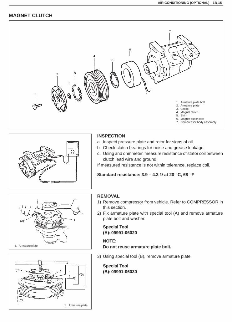
1. Armature plate bolt2. Armature plate3. Circlip4. Magnet clutch5. Shim6. Magnet clutch coil7. Compressor body assembly
1. Armature plate
1. Armature plate
5
6
7
MAGNET CLUTCH
INSPECTIONa. Inspect pressure plate and rotor for signs of oil.b. Check clutch bearings for noise and grease leakage.c. Using and ohmmeter, measure resistance of stator coil between
clutch lead wire and ground.If measured resistance is not within tolerance, replace coil.
Standard resistance: 3.9 – 4.3 � at 20 �C, 68 �F
REMOVAL1) Remove compressor from vehicle. Refer to COMPRESSOR in
this section.2) Fix armature plate with special tool (A) and remove armature
plate bolt and washer.
Special Tool(A): 09991-06020
NOTE:Do not reuse armature plate bolt.
3) Using special tool (B), remove armature plate.
Special Tool(B): 09991-06030
SQHokubei(Supple)
1B-16 AIR CONDITIONING (OPTIONAL)
1. Puller2. Compressor
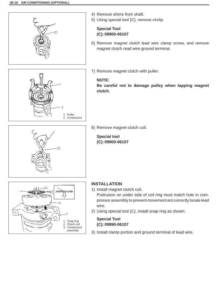
1. Snap ring2. Clutch coil3. Compressor
assembly
2
4) Remove shims from shaft.5) Using special tool (C), remove circlip.
Special Tool(C): 09900-06107
6) Remove magnet clutch lead wire clamp screw, and removemagnet clutch read wire ground terminal.
7) Remove magnet clutch with puller.
NOTE:Be careful not to damage pulley when tapping magnetclutch.
8) Remove magnet clutch coil.
Special tool(C): 09900-06107
INSTALLATION1) Install magnet clutch coil.
Protrusion on under side of coil ring must match hole in com-pressor assembly to prevent movement ant correctly locate leadwire.
2) Using special tool (C), install snap ring as shown.
Special Tool(C): 09990-06107
3) Install clamp portion and ground terminal of lead wire.
SQHokubei(Supple)
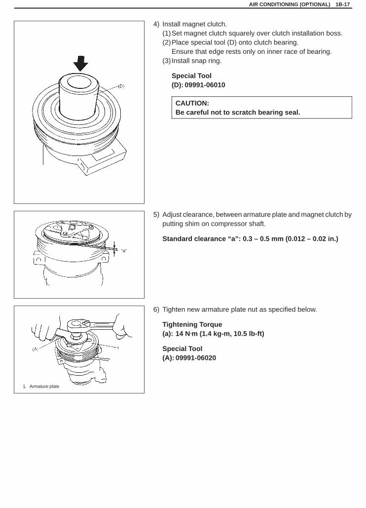
1. Armature plate
“a”
AIR CONDITIONING (OPTIONAL) 1B-17
4) Install magnet clutch.(1)Set magnet clutch squarely over clutch installation boss.(2)Place special tool (D) onto clutch bearing.
Ensure that edge rests only on inner race of bearing.(3) Install snap ring.
Special Tool(D): 09991-06010
CAUTION:Be careful not to scratch bearing seal.
5) Adjust clearance, between armature plate and magnet clutch byputting shim on compressor shaft.
Standard clearance “a”: 0.3 – 0.5 mm (0.012 – 0.02 in.)
6) Tighten new armature plate nut as specified below.
Tightening Torque(a): 14 N.m (1.4 kg-m, 10.5 lb-ft)
Special Tool(A): 09991-06020
SQHokubei(Supple)
1B-18 AIR CONDITIONING (OPTIONAL)
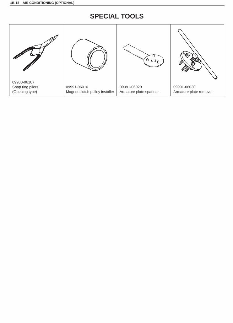
09900-06107Snap ring pliers(Opening type)
09991-06010Magnet clutch pulley installer
09991-06020Armature plate spanner
09991-06030Armature plate remover
SPECIAL TOOLS
SQHokubei(Supple)
3B1
POWER STEERING (P /S) SYSTEM 3B1-1
SECTION 3B1
POWER STEERING (P/S) SYSTEMWARNING:For vehicles equipped with Supplemental Restraint (Air Bag) System:� Service on and around the air bag system components or wiring must be performed only by an autho-
rized SUZUKI dealer. Refer to “Air Bag System Components and Wiring Location View” under “Gener-al Description” in air bag system section in order to confirm whether you are performing service onor near the air bag system components or wiring. Please observe all WARNINGS and “Service Precau-tions” under “On-Vehicle Service” in air bag system section before performing service on or aroundthe air bag system components or wiring. Failure to follow WARNINGS could result in unintentionalactivation of the system or could render the system inoperative. Either of these two conditions mayresult in severe injury.
� Technical service work must be started at least 90 seconds after the ignition switch is turned to the“LOCK” position and the negative cable is disconnected from the battery. Otherwise, the system maybe activated by reserve energy in the Sensing and Diagnostic Module (SDM).
NOTE:� For the descriptions (items) not found in this section, refer to the same section of the Service Manual
mentioned in FOREWORD of this manual.� Power Steering Gear Box cannot be disassembled or adjusted.� All steering gear fasteners are important attaching parts in that they could affect the performance of vital
parts and systems, and/or could result in major repair expense. They must be replaced with one of thesame part number or with an equivalent part if replacement becomes necessary. Do not use a replace-ment part of lesser quality or substitute design. Torque values must be used as specified during reas-sembly to assure proper retention of these parts.
CONTENTS
GENERAL DESCRIPTION 3B1- 2. . . . . . . . . . . . . . . . . . . . . . . . . . . . . . . . . . . . . . . . . . . . . . . . . . . . . . . . . . . . . . . . . .
ON-VEHICLE SERVICE 3B1- 3. . . . . . . . . . . . . . . . . . . . . . . . . . . . . . . . . . . . . . . . . . . . . . . . . . . . . . . . . . . . . . . . . . . . Rack Boot/Tie-rod 3B1- 3. . . . . . . . . . . . . . . . . . . . . . . . . . . . . . . . . . . . . . . . . . . . . . . . . . . . . . . . . . . . . . . . . . . . . . . . Power Steering Pump 3B1- 5. . . . . . . . . . . . . . . . . . . . . . . . . . . . . . . . . . . . . . . . . . . . . . . . . . . . . . . . . . . . . . . . . . . . .
TIGHTENING TORQUE SPECIFICATIONS 3B1- 6. . . . . . . . . . . . . . . . . . . . . . . . . . . . . . . . . . . . . . . . . . . . . . . . . . . .
SPECIAL TOOL 3B1- 6. . . . . . . . . . . . . . . . . . . . . . . . . . . . . . . . . . . . . . . . . . . . . . . . . . . . . . . . . . . . . . . . . . . . . . . . . . .

SQHokubei(Supple)
1. Power steering gear box2. Power steering pump3. Oil tank
3B1-2 POWER STEERING (P /S) SYSTEM
GENERAL DESCRIPTION
The power steering (P/S) system in this vehicle reduces the driver’s effort needed in turning the steering wheelby utilizing the hydraulic pressure generated by the power steering (P/S) pump which is driven by the engine.It is an integral type with the rack and pinion gears and the control valve unit, hydraulic pressure cylinder unit allbuilt in the steering gear box.
SQHokubei(Supple)
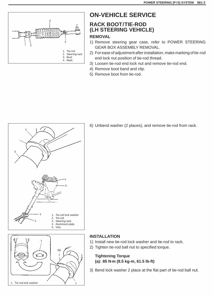
1. Tie-rod2. Steering rack3. Boot4. Mark
11. Tie-rod lock washer
1. Tie-rod lock washer2. Tie-rod3. Steering rack4. Aluminium plate5. Vise
POWER STEERING (P /S) SYSTEM 3B1-3
ON-VEHICLE SERVICE
RACK BOOT/TIE-ROD(LH STEERING VEHICLE)REMOVAL1) Remove steering gear case, refer to POWER STEERING
GEAR BOX ASSEMBLY REMOVAL.2) For ease of adjustment after installation, make marking of tie-rod
end lock nut position of tie-rod thread.3) Loosen tie-rod end lock nut and remove tie-rod end.4) Remove boot band and clip.5) Remove boot from tie-rod.
6) Unbend washer (2 places), and remove tie-rod from rack.
INSTALLATION1) Install new tie-rod lock washer and tie-rod to rack.2) Tighten tie-rod ball nut to specified torque.
Tightening Torque(a): 85 N.m (8.5 kg-m, 61.5 lb-ft)
3) Bend lock washer 2 place at the flat part of tie-rod ball nut.
SQHokubei(Supple)
3B1-4 POWER STEERING (P /S) SYSTEM
(A)
“A”
1
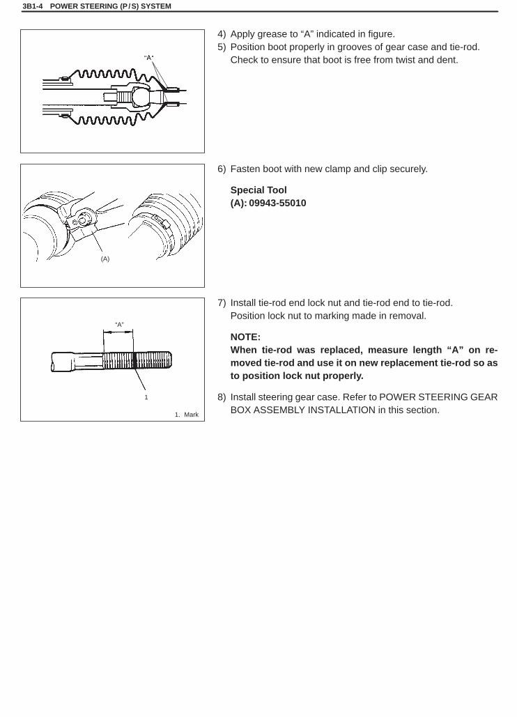
1. Mark
4) Apply grease to “A” indicated in figure.5) Position boot properly in grooves of gear case and tie-rod.
Check to ensure that boot is free from twist and dent.
6) Fasten boot with new clamp and clip securely.
Special Tool(A): 09943-55010
7) Install tie-rod end lock nut and tie-rod end to tie-rod.Position lock nut to marking made in removal.
NOTE:When tie-rod was replaced, measure length “A” on re-moved tie-rod and use it on new replacement tie-rod so asto position lock nut properly.
8) Install steering gear case. Refer to POWER STEERING GEARBOX ASSEMBLY INSTALLATION in this section.

SQHokubei(Supple)
POWER STEERING (P /S) SYSTEM 3B1-5
Tightening Torque(a): 60 N.m (6.0 kg-m, 43.5 lb-ft)(b):25 N.m (2.5 kg-m, 18.5 lb-ft)(c): 55 N.m (5.5 kg-m, 40.0 lb-ft)(e): 35 N.m (3.5 kg-m, 25.5 lb-ft)(f): 40 N.m (4.0 kg-m, 29.0 lb-ft)
1. Power steering pump assembly2. Bracket3. Power steering oil tank
4. High pressure hose & pipe5. Suction hose
6. Low pressure return hose7. Oil tank bracket
[A]: G16 Type engine[B]: J20 Type engine
[A]
[B]
POWER STEERING PUMP
SQHokubei(Supple)
3B1-6 POWER STEERING (P /S) SYSTEM
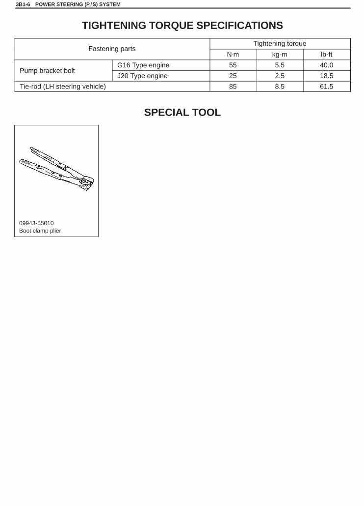
09943-55010Boot clamp plier
TIGHTENING TORQUE SPECIFICATIONS
Fastening partsTightening torque
Fastening artsN.m kg-m lb-ft
Pump bracket boltG16 Type engine 55 5.5 40.0
Pump bracket boltJ20 Type engine 25 2.5 18.5
Tie-rod (LH steering vehicle) 85 8.5 61.5
SPECIAL TOOL
3C1
AIR BAG STEERING WHEEL AND COLUMN 3C1-1
SECTION 3C1
AIR BAG STEERING WHEEL AND COLUMNWARNING:� Service on and around the air bag system components or wiring must be performed only by an autho-
rized SUZUKI dealer. Please observe all WARNINGS and “Service Precautions” under “On-VehicleService” in air bag system section before performing service on or around the air bag system compo-nents or wiring. Failure to follow WARNINGS could result in unintentional activation of the systemor could render the system inoperative. Either of these two conditions may result in severe injury.
� The procedures in this section must be followed in the order listed to disable the air bag system tem-porarily and prevent false diagnostic trouble codes from setting. Failure to follow procedures couldresult in possible activation of the air bag system, personal injury or otherwise unneeded air bag sys-tem repairs.
CAUTION:When fasteners are removed, always reinstall them at the same location from which they were re-moved. If a fastener needs to be replaced, use the correct part number fastener for that application. Ifthe correct part number fastener is not available, a fastener of equal size and strength (or stronger) maybe used. Fasteners that are not reused, and those requiring thread-locking compound, will be calledout. The correct torque value must be used when installing fasteners that require it. If the above proce-dures are not followed, parts or system damage could result.
NOTE:For the descriptions (items) not found in this section, refer to the same section of the Service Manual men-tioned in FOREWORD of this manual.
CONTENTS
GENERAL DESCRIPTION 3C1- 2. . . . . . . . . . . . . . . . . . . . . . . . . . . . . . . . . . . . . . . . . . . . . . . . . . . . . . . . . . . . . . . .
ON-VEHICLE SERVICE 3C1- 3. . . . . . . . . . . . . . . . . . . . . . . . . . . . . . . . . . . . . . . . . . . . . . . . . . . . . . . . . . . . . . . . . . Driver air bag (inflator) module 3C1- 3. . . . . . . . . . . . . . . . . . . . . . . . . . . . . . . . . . . . . . . . . . . . . . . . . . . . . . . . . . .
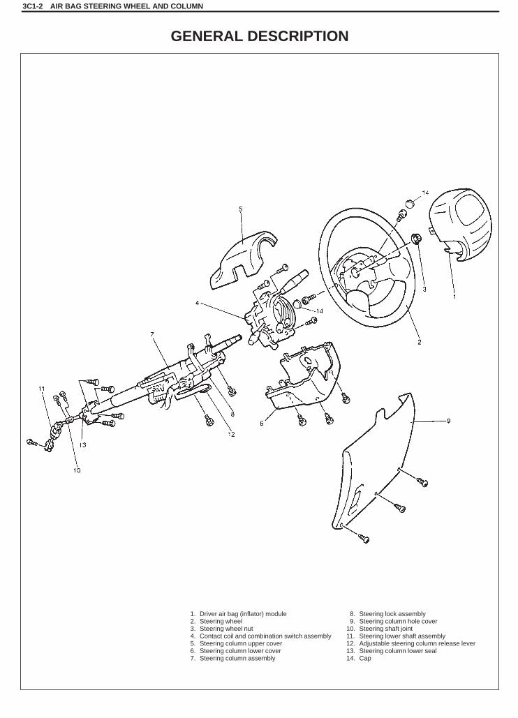
1. Driver air bag (inflator) module2. Steering wheel3. Steering wheel nut4. Contact coil and combination switch assembly5. Steering column upper cover6. Steering column lower cover7. Steering column assembly
8. Steering lock assembly9. Steering column hole cover
10. Steering shaft joint11. Steering lower shaft assembly12. Adjustable steering column release lever13. Steering column lower seal14. Cap
3C1-2 AIR BAG STEERING WHEEL AND COLUMN
GENERAL DESCRIPTION
AIR BAG STEERING WHEEL AND COLUMN 3C1-3
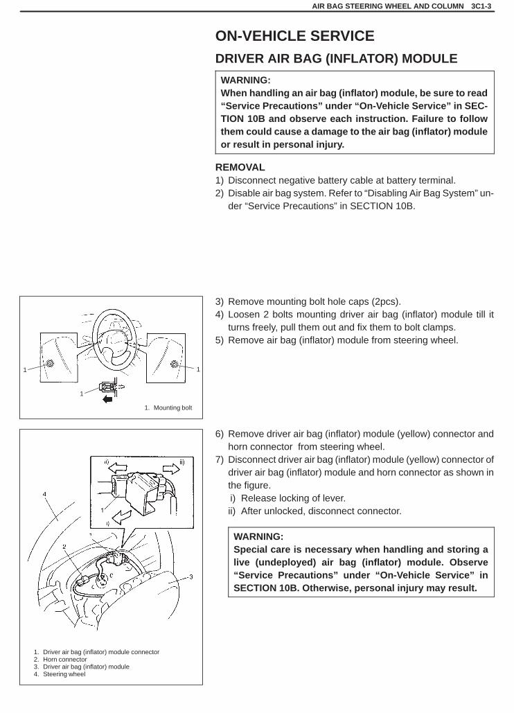
1. Mounting bolt
1. Driver air bag (inflator) module connector2. Horn connector3. Driver air bag (inflator) module4. Steering wheel
1
1 1
ON-VEHICLE SERVICE
DRIVER AIR BAG (INFLATOR) MODULE
WARNING:When handling an air bag (inflator) module, be sure to read“Service Precautions” under “On-Vehicle Service” in SEC-TION 10B and observe each instruction. Failure to followthem could cause a damage to the air bag (inflator) moduleor result in personal injury.
REMOVAL1) Disconnect negative battery cable at battery terminal.2) Disable air bag system. Refer to “Disabling Air Bag System” un-
der “Service Precautions” in SECTION 10B.
3) Remove mounting bolt hole caps (2pcs).4) Loosen 2 bolts mounting driver air bag (inflator) module till it
turns freely, pull them out and fix them to bolt clamps.5) Remove air bag (inflator) module from steering wheel.
6) Remove driver air bag (inflator) module (yellow) connector andhorn connector from steering wheel.
7) Disconnect driver air bag (inflator) module (yellow) connector ofdriver air bag (inflator) module and horn connector as shown inthe figure.ii) Release locking of lever.ii) After unlocked, disconnect connector.
WARNING:Special care is necessary when handling and storing alive (undeployed) air bag (inflator) module. Observe“Service Precautions” under “On-Vehicle Service” inSECTION 10B. Otherwise, personal injury may result.
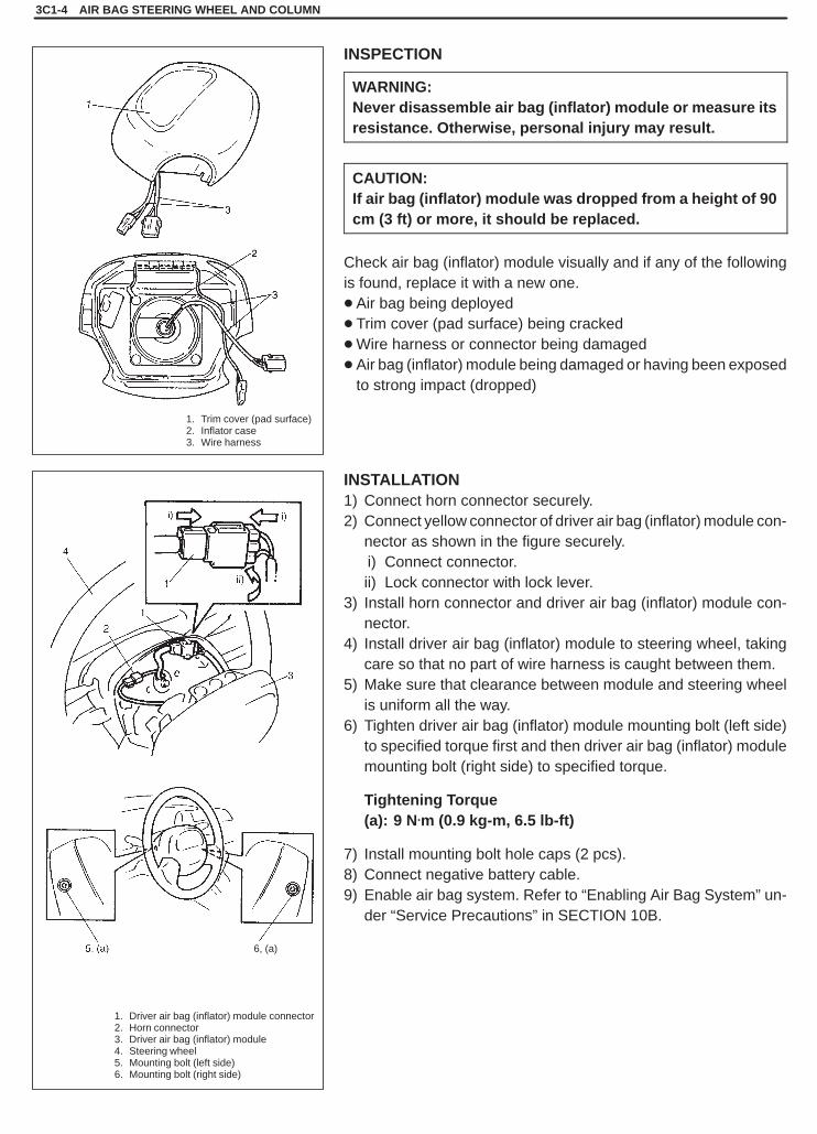
1. Trim cover (pad surface)2. Inflator case3. Wire harness
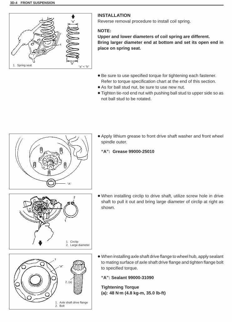
1. Driver air bag (inflator) module connector2. Horn connector3. Driver air bag (inflator) module4. Steering wheel5. Mounting bolt (left side)6. Mounting bolt (right side)
6, (a)
3C1-4 AIR BAG STEERING WHEEL AND COLUMN
INSPECTION
WARNING:Never disassemble air bag (inflator) module or measure itsresistance. Otherwise, personal injury may result.
CAUTION:If air bag (inflator) module was dropped from a height of 90cm (3 ft) or more, it should be replaced.
Check air bag (inflator) module visually and if any of the followingis found, replace it with a new one.� Air bag being deployed� Trim cover (pad surface) being cracked�Wire harness or connector being damaged� Air bag (inflator) module being damaged or having been exposed
to strong impact (dropped)
INSTALLATION1) Connect horn connector securely.2) Connect yellow connector of driver air bag (inflator) module con-
nector as shown in the figure securely.ii) Connect connector.ii) Lock connector with lock lever.
3) Install horn connector and driver air bag (inflator) module con-nector.
4) Install driver air bag (inflator) module to steering wheel, takingcare so that no part of wire harness is caught between them.
5) Make sure that clearance between module and steering wheelis uniform all the way.
6) Tighten driver air bag (inflator) module mounting bolt (left side)to specified torque first and then driver air bag (inflator) modulemounting bolt (right side) to specified torque.
Tightening Torque(a): 9 N.m (0.9 kg-m, 6.5 lb-ft)
7) Install mounting bolt hole caps (2 pcs).8) Connect negative battery cable.9) Enable air bag system. Refer to “Enabling Air Bag System” un-
der “Service Precautions” in SECTION 10B.

SQHokubei(Supple)
3D
FRONT SUSPENSION 3D-1
SECTION 3D
FRONT SUSPENSIONCAUTION:� All front suspension fasteners are an important attaching part in that it could affect the performance
of vital parts and systems, and/or could result in major repair expense. They must be replaced withone of the same part number or with an equivalent part if replacement becomes necessary. Do notuse a replacement part of lesser quality or substitute design. Torque values must be used as specifiedduring reassembly to assure proper retention of this part.
�Never attempt to heat, quench or straighten any front suspension part. Replace it with a new part ordamage to the part may result.
NOTE:For the descriptions (items) not found in this section, refer to the same section of the Service Manual men-tioned in FOREWORD of this manual.
CONTENTS
ON-VEHICLE SERVICE 3D- 2. . . . . . . . . . . . . . . . . . . . . . . . . . . . . . . . . . . . . . . . . . . . . . . . . . . . . . . . . . . . . . . . . . . . Coil Spring 3D- 2. . . . . . . . . . . . . . . . . . . . . . . . . . . . . . . . . . . . . . . . . . . . . . . . . . . . . . . . . . . . . . . . . . . . . . . . . . . . . . Knuckle/Wheel Spindle 3D- 6. . . . . . . . . . . . . . . . . . . . . . . . . . . . . . . . . . . . . . . . . . . . . . . . . . . . . . . . . . . . . . . . . . . .
TIGHTENING TORQUE SPECIFICATIONS 3D- 9. . . . . . . . . . . . . . . . . . . . . . . . . . . . . . . . . . . . . . . . . . . . . . . . . . . .

SQHokubei(Supple)
1. Circlip2. Washer
1. Wire
1. Front wheelspeed sensor
2. Harness clamp bolt
3D-2 FRONT SUSPENSION
ON-VEHICLE SERVICE
COIL SPRINGREMOVAL1) Hoist vehicle, allowing front suspension to hang free.2) Remove wheels.3) Remove axle shaft drive flange.
4) Remove front drive shaft circlip and washer.
5) Remove caliper bolts and suspend caliper with a wire hook.
CAUTION:Hang removed caliper with a wire hook so as to preventbrake hose from bending and twisting excessively or be-ing pulled.Don’t operate brake pedal with pads removed.
6) If equipped with ABS, remove harness clamp bolt and removefront wheel speed sensor from knuckle.
CAUTION:�Do not pull wire harness when removing front wheel
speed sensor.�Do not cause damage to surface of front wheel speed
sensor and do not allow dust, etc. to enter its installa-tion hole.
7) Remove brake disc.
NOTE:If brake disc can not be removed by hand, use 8 mm boltsas shown.

SQHokubei(Supple)
1. Coil spring
FRONT SUSPENSION 3D-3
8) Remove stabilizer bar, refer to steps 2) to 5) of item STABILIZ-ER BAR/BUSHINGS REMOVAL in this section.
9) Disconnect tie rod end from knuckle by using puller.
10) Support lower arm, using jack as shown.
11) Remove strut bracket bolts.
12) Remove ball stud nut.13) Using puller, disconnect knuckle from ball stud.
14) Remove knuckle and wheel hub comp, while lowering jack.15) Remove coil spring.
SQHokubei(Supple)
“a” < “b”
“A”
1. Circlip2. Large diameter
1. Axle shaft drive flange2. Bolt
1. Spring seat
2, (a)
3D-4 FRONT SUSPENSION
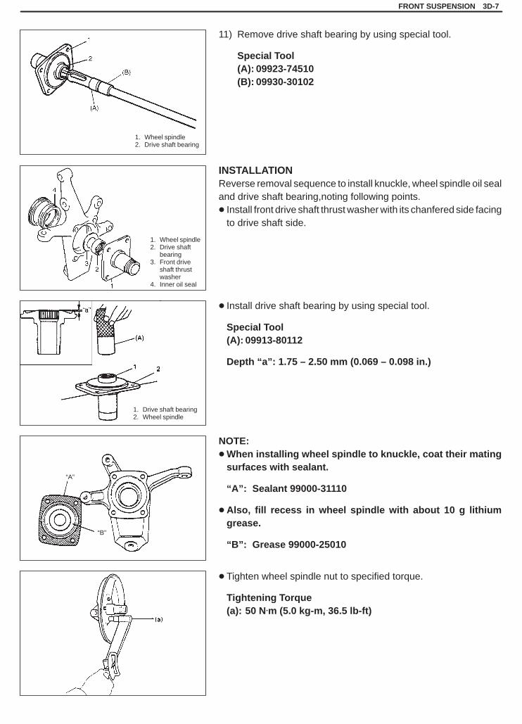
INSTALLATIONReverse removal procedure to install coil spring.
NOTE:Upper and lower diameters of coil spring are different.Bring larger diameter end at bottom and set its open end inplace on spring seat.
� Be sure to use specified torque for tightening each fastener.Refer to torque specification chart at the end of this section.
� As for ball stud nut, be sure to use new nut.� Tighten tie-rod end nut with pushing ball stud to upper side so as
not ball stud to be rotated.
� Apply lithium grease to front drive shaft washer and front wheelspindle outer.
“A”: Grease 99000-25010
�When installing circlip to drive shaft, utilize screw hole in driveshaft to pull it out and bring large diameter of circlip at right asshown.
�When installing axle shaft drive flange to wheel hub, apply sealantto mating surface of axle shaft drive flange and tighten flange boltto specified torque.
“A”: Sealant 99000-31090
Tightening Torque(a): 48 N.m (4.8 kg-m, 35.0 lb-ft)

SQHokubei(Supple)
1. Front wheel speed sensor2. Bolt
2, (b)
1
FRONT SUSPENSION 3D-5
�Check that no foreign material is attached to sensor and rotor.Install wheel speed sensor and its harness clamp.
Tightening Torque(a): 10 N.m (1.0 kg-m, 7.5 lb-ft)(b): 23 N.m (2.3 kg-m, 17.0 lb-ft)
CAUTION:�Do not pull wire harness or twist more than necessary
when installing front wheel speed sensor.� Fit harness grommet to inner fender securely.
�Check that there is no clearance between sensor and knuckle.

SQHokubei(Supple)
3D-6 FRONT SUSPENSION
1. Strut2. Knuckle
1. Dust cover2. Wheel spindle3. Knuckle4. Inner oil seal
KNUCKLE/WHEEL SPINDLEREMOVAL
1) Hoist vehicle and remove wheel.2) Remove axle shaft drive flange, drive shaft circlip and washer.
Refer to steps 3) to 4) of item COIL SPRING REMOVAL in thissection.
3) Remove wheel hub. Refer to steps 3) to 9) of item WHEELHUB/BEARING/OIL SEAL REMOVAL in this section.
4) Disconnect tie-rod end from knuckle.
5) Remove ball stud nut.6) Support lower arm with jack.7) Remove strut bracket bolts from strut bracket.
8) By using puller, disconnect knuckle from ball stud.
9) While lowering jack, remove knuckle/wheel spindle comp.10) Remove inner oil seal, dust cover and wheel spindle.
SQHokubei(Supple)
FRONT SUSPENSION 3D-7
1. Wheel spindle2. Drive shaft bearing
1. Wheel spindle2. Drive shaft
bearing3. Front drive
shaft thrustwasher
4. Inner oil seal
1. Drive shaft bearing2. Wheel spindle
“A”
“B”
11) Remove drive shaft bearing by using special tool.
Special Tool(A): 09923-74510(B): 09930-30102
INSTALLATIONReverse removal sequence to install knuckle, wheel spindle oil sealand drive shaft bearing,noting following points.� Install front drive shaft thrust washer with its chanfered side facing
to drive shaft side.
� Install drive shaft bearing by using special tool.
Special Tool(A): 09913-80112
Depth “a”: 1.75 – 2.50 mm (0.069 – 0.098 in.)
NOTE:�When installing wheel spindle to knuckle, coat their mating
surfaces with sealant.
“A”: Sealant 99000-31110
� Also, fill recess in wheel spindle with about 10 g lithiumgrease.
“B”: Grease 99000-25010
� Tighten wheel spindle nut to specified torque.
Tightening Torque(a): 50 N.m (5.0 kg-m, 36.5 lb-ft)
SQHokubei(Supple)
3D-8 FRONT SUSPENSION
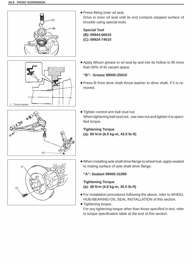
1. Thrust washer
(a)
� Press-fitting inner oil seal.Drive in inner oil seal until its end contacts stepped surface ofknuckle using special tools.
Special Tool(B): 09944-66010(C): 09924-74510
� Apply lithium grease to oil seal lip and into its hollow to fill morethan 60% of its vacant space.
“B”: Grease 99000-25010
� Press-fit front drive shaft thrust washer to drive shaft, if it is re-moved.
� Tighten control arm ball stud nut.When tightening ball stud nut, use new nut and tighten it to speci-fied torque.
Tightening Torque(a): 60 N.m (6.0 kg-m, 43.5 lb-ft)
�When installing axle shaft drive flange to wheel hub, apply sealantto mating surface of axle shaft drive flange.
“A”: Sealant 99000-31090
Tightening Torque(a): 48 N.m (4.8 kg-m, 35.0 lb-ft)
� For installation procedures following the above, refer to WHEELHUB/BEARING/OIL SEAL INSTALLATION of this section.
� Tightening torque.For any tightening torque other than those specified in text, referto torque specification table at the end of this section.

SQHokubei(Supple)
FRONT SUSPENSION 3D-9
[D]
[A]
48 N.m
[C]
[B]
60 N.m
TIGHTENING TORQUE SPECIFICATIONS
SQHokubei(Supple)
3E
REAR SUSPENSION 3E-1
SECTION 3E
REAR SUSPENSIONNOTE:� All suspension fasteners are an important attaching part in that it could affect the performance of vital
parts and systems, and/or could result in major repair expense. They must be replaced with one of thesame part number or with an equivalent part if replacement becomes necessary. Do not use a replace-ment part of lesser quality or substitute design. Torque values must be used as specified during reas-sembly to assure proper retention of this part.
�Never attempt to heat, quench or straighten any suspension part. Replace it with a new part, or damageto the part may result.
� For the descriptions (items) not found in this section, refer to the same section of the Service Manualmentioned in FOREWORD of this manual.
CONTENTS
ON-VEHICLE SERVICE 3E- 2. . . . . . . . . . . . . . . . . . . . . . . . . . . . . . . . . . . . . . . . . . . . . . . . . . . . . . . . . . . . . . . . . . . . Shock Absorber 3E- 2. . . . . . . . . . . . . . . . . . . . . . . . . . . . . . . . . . . . . . . . . . . . . . . . . . . . . . . . . . . . . . . . . . . . . . . . . . Lower Rod 3E- 3. . . . . . . . . . . . . . . . . . . . . . . . . . . . . . . . . . . . . . . . . . . . . . . . . . . . . . . . . . . . . . . . . . . . . . . . . . . . . . Rear Axle Shaft Inner Oil Seal 3E- 4. . . . . . . . . . . . . . . . . . . . . . . . . . . . . . . . . . . . . . . . . . . . . . . . . . . . . . . . . . . . . .
SPECIAL TOOL 3E- 4. . . . . . . . . . . . . . . . . . . . . . . . . . . . . . . . . . . . . . . . . . . . . . . . . . . . . . . . . . . . . . . . . . . . . . . . . . .

SQHokubei(Supple)
1. Rear axle housing2. Floor jack
1. Blank2. Absorber nut3. Upper support4. Rubber bush5. Lower support6. Shock absorber7. Bolt
Upper side
Lower side
* Body Outside
*
3E-2 REAR SUSPENSION
ON-VEHICLE SERVICE
SHOCK ABSORBER
The shock absorber is non-adjustable, non-refillable, and cannotbe disassembled. The only service the shock absorber requires isreplacement when it has lost its resistance, is damaged, or leakingfluid.
REMOVAL1) Hoist vehicle and remove rear wheel.2) Support rear axle housing by using floor jack to prevent it from
lowering.
3) Remove absorber nut.4) Remove lower mounting bolt.5) Remove shock absorber.
INSTALLATION1) Install shock absorber. Refer to figure for proper installing direc-
tion of lower mounting bolt.2) Remove floor jack.3) Lower hoist.4) Tighten nuts to specified torque.
NOTE:� Tighten lower nut with vehicle off hoist and in non-loaded
condition.�Use new absorber nut.
Tightening Torque(a): 29 N.m (2.9 kg-m, 21.0 lb-ft)(b): 85 N.m (8.5 kg-m. 61.5 lb-ft)

SQHokubei(Supple)
1. Axle housing2. Floor jack
1. Lower rod2. Rear mount nut
1. Lower rod2. Front mount bolt
1. Lower rod2. Front bolt3. Rear bolt4. Vehicle body5. Axle housing6. Body center7. Body out side
Body side Axle side
REAR SUSPENSION 3E-3
LOWER RODREMOVAL1) Hoist vehicle and remove rear wheel.2) Support rear axle housing by using floor jack.
3) Remove lower rod front mount bolt.
4) Remove lower rod rear mount bolt.
INSTALLATION1) Install lower rod to chassis frame and axle housing, referring to
figure for proper installing direction of bolts.
Nuts should not be tightened.
2) Remove floor jack from rear axle housing.3) Install wheel and tighten wheel nuts to specified torque.
Tightening Torque for wheel nuts95 N.m (9.5 kg-m, 69.0 lb-ft)
4) Lower hoist and with vehicle in non loaded condition, tightenfront bolts and rear bolts and nuts of lower rod to specifiedtorque.
Tightening Torque(a): 90 N.m (9.0 kg-m, 65.0 lb-ft)
SQHokubei(Supple)
3E-4 REAR SUSPENSION
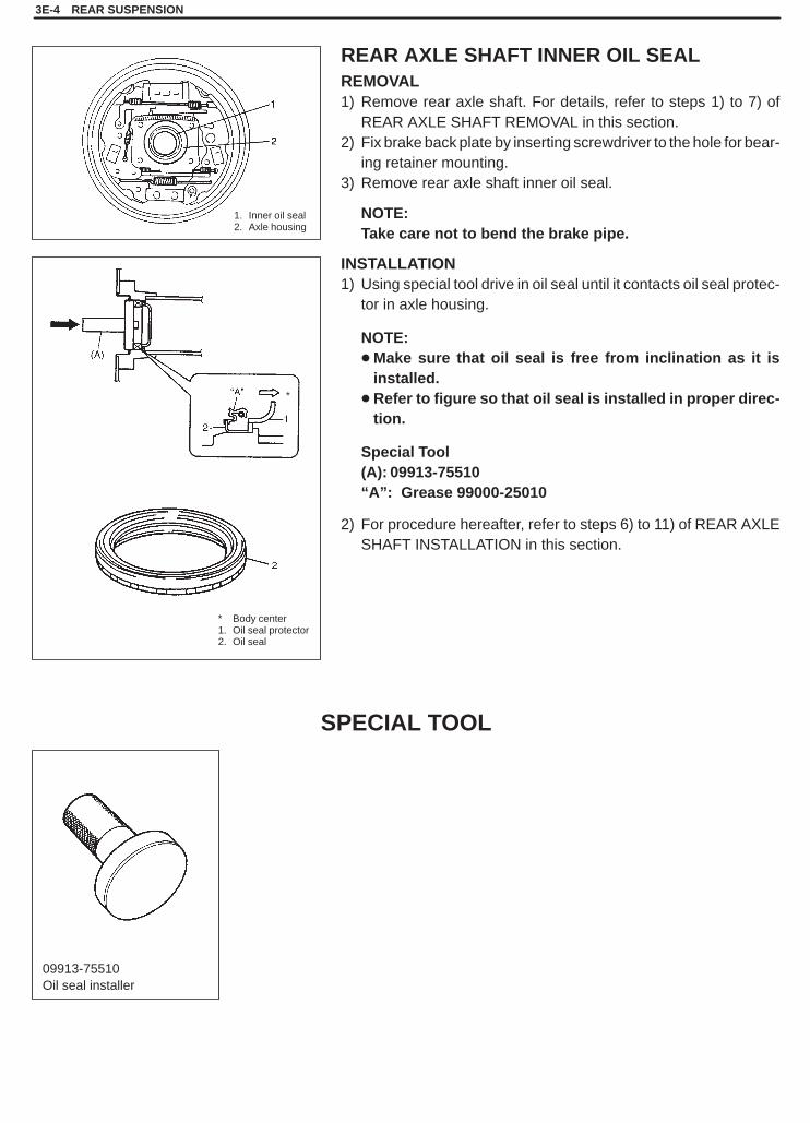
1. Inner oil seal2. Axle housing
* Body center1. Oil seal protector2. Oil seal
*
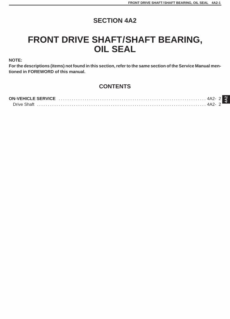
09913-75510Oil seal installer
REAR AXLE SHAFT INNER OIL SEALREMOVAL1) Remove rear axle shaft. For details, refer to steps 1) to 7) of
REAR AXLE SHAFT REMOVAL in this section.2) Fix brake back plate by inserting screwdriver to the hole for bear-
ing retainer mounting.3) Remove rear axle shaft inner oil seal.
NOTE:Take care not to bend the brake pipe.
INSTALLATION1) Using special tool drive in oil seal until it contacts oil seal protec-
tor in axle housing.
NOTE:�Make sure that oil seal is free from inclination as it is
installed.�Refer to figure so that oil seal is installed in proper direc-
tion.
Special Tool(A): 09913-75510“A”: Grease 99000-25010
2) For procedure hereafter, refer to steps 6) to 11) of REAR AXLESHAFT INSTALLATION in this section.
SPECIAL TOOL

SQHokubei(Supple)
3F
WHEELS AND TIRES 3F-1
SECTION 3F
WHEELS AND TIRESNOTE:� All wheel fasteners are important attaching parts in that they could affect the performance of vital parts
and systems, and/or could result in major repair expense. They must be replaced with one of the samepart number or with an equivalent part if replacement becomes necessary. Do not use a replacement partof lesser quality or substitute design. Torque values must be used as specified during reassembly to as-sure proper retention of all parts.There is to be no welding as it may result in extensive damage and weakening of the metal.
� For the descriptions (items) not found in this section, refer to the same section of the Service Manualmentioned in FOREWORD of this manual.
CONTENTS
GENERAL DESCRIPTION 3F- 1. . . . . . . . . . . . . . . . . . . . . . . . . . . . . . . . . . . . . . . . . . . . . . . . . . . . . . . . . . . . . . . . . . Tires 3F- 1. . . . . . . . . . . . . . . . . . . . . . . . . . . . . . . . . . . . . . . . . . . . . . . . . . . . . . . . . . . . . . . . . . . . . . . . . . . . . . . . . . . . Wheels 3F- 1. . . . . . . . . . . . . . . . . . . . . . . . . . . . . . . . . . . . . . . . . . . . . . . . . . . . . . . . . . . . . . . . . . . . . . . . . . . . . . . . .
ON-VEHICLE SERVICE 3F- 2. . . . . . . . . . . . . . . . . . . . . . . . . . . . . . . . . . . . . . . . . . . . . . . . . . . . . . . . . . . . . . . . . . . . Tire 3F- 2. . . . . . . . . . . . . . . . . . . . . . . . . . . . . . . . . . . . . . . . . . . . . . . . . . . . . . . . . . . . . . . . . . . . . . . . . . . . . . . . . . . . .
GENERAL DESCRIPTION
TIRES
This vehicle is equipped with following tire, depending on vehicle specification.P205/75 R15 (1.6�) or P215/65 R16 (2.0�)The tires are of tubeless type. The tires are designed to operate satisfactorily with loads up to the full rated loadcapacity when inflated to the recommended inflation pressure.Correct tire pressures and driving habits have an important influence on tire life. Heavy cornering, excessively rapidacceleration, and unnecessary sharp braking increase tire wear.
WHEELS
Standard equipment wheels are following steel wheels.15 x 5 1/2 JJ (1.6�) or 16 x 6 1/2 J (2.0�)

SQHokubei(Supple)
3F-2 WHEELS AND TIRES
ON-VEHICLE SERVICE
TIREMOUNTING AND DEMOUNTINGUse tire changing machine to mount or demount tires. Follow equip-ment manufacturer’s instructions. Do not use hand tools or tireirons alone to change tires as they may damage tire beads or wheelrim.Rim bead seats should be cleaned with wire brush or coarse steelwool to remove lubricants, old rubber and light rust. Before mount-ing or demounting tire, bead area should be well lubricated with ap-proved tire lubricant.After mounting, inflate to 240 kPa (35 psi) so that beads are com-pletely seated.Then adjust pressure to specified shown on tire placard.
WARNING:Do not stand over tire when inflating. Bead may break whenbead snaps over rim’s safety hump and cause serious per-sonal injury.Do not exceed 240 kPa (35 psi) pressure when inflating. If240 kPa (35 psi) pressure will not seat beads, deflate, re-lu-bricate and reinflate. Over inflation may cause bead to breakand cause serious personal injury.
Install valve core and inflate to proper pressure.
TIRE REPAIRThere are many different materials and techniques on the marketto repair tires. As not all of these work on all types of tires, tiremanufacturers have published detailed instructions on how andwhen to repair tires. These instructions can be obtained from thetire manufacturer.
SQHokubei(Supple)
4A2
FRONT DRIVE SHAFT/SHAFT BEARING, OIL SEAL 4A2-1
SECTION 4A2
FRONT DRIVE SHAFT/SHAFT BEARING,OIL SEAL
NOTE:For the descriptions (items) not found in this section, refer to the same section of the Service Manual men-tioned in FOREWORD of this manual.
CONTENTS
ON-VEHICLE SERVICE 4A2- 2. . . . . . . . . . . . . . . . . . . . . . . . . . . . . . . . . . . . . . . . . . . . . . . . . . . . . . . . . . . . . . . . . . . . Drive Shaft 4A2- 2. . . . . . . . . . . . . . . . . . . . . . . . . . . . . . . . . . . . . . . . . . . . . . . . . . . . . . . . . . . . . . . . . . . . . . . . . . . . . .

SQHokubei(Supple)
1. Oil filler / level plug2. Front drain plug
1. Circlip2. Washer
1. Drive shaft flange bolts and nuts
1. Oil seal
4A2-2 FRONT DRIVE SHAFT/SHAFT BEARING, OIL SEAL
ON-VEHICLE SERVICE
DRIVE SHAFTREMOVAL (LEFT SIDE)1) Hoist vehicle and remove wheel.
2) Remove axle shaft drive flange.3) Remove drive shaft circlip and washer.
4) Remove drive shaft flange bolts and nuts.
5) Remove drive shaft assembly to differential side as shown in leftfigure.
CAUTION:To prevent breakage of boots (wheel side and differentialside), be careful not to bring them into contact with otherparts when removing drive shaft assembly.
6) Remove drive shaft thrust washer from drive shaft and removedrive shaft oil seal as shown in figure.
CAUTION:Be careful not to cause damage to drive shaft joint.

SQHokubei(Supple)
1. Oil filler / level plug2. Front drain plug
1. Circlip2. Washer
1. Differential side joint2. Tire lever3. Front differential assembly
1. Oil seal
2
1
FRONT DRIVE SHAFT/SHAFT BEARING, OIL SEAL 4A2-3
REMOVAL (RIGHT SIDE)1) Hoist vehicle and remove wheel.2) Drain differential gear oil.
3) Remove axle shaft drive flange.4) Remove drive shaft circlip and washer.5) Remove knuckle and wheel hub comp, refer to steps 5) to 7) and
9) to 14) of item COIL SPRING REMOVAL in Section 3D.
6) Remove drive shaft assembly.To detach snap ring fitted on the spline of differential side joint(inboard joint) from differential side gear, pull inboard joint by us-ing a tire lever.
CAUTION:To prevent breakage of boots (wheel side and differentialside), be careful not to bring them into contact with otherparts when removing drive shaft assembly.
7) Remove drive shaft thrust washer from drive shaft and removedrive shaft oil seal as shown in figure.
CAUTION:Be careful not to cause damage to drive shaft joint.
SQHokubei(Supple)
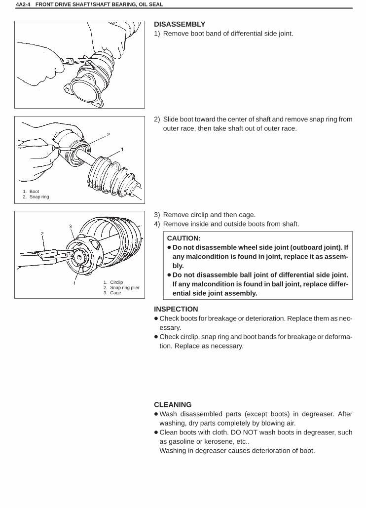
1. Boot2. Snap ring
1. Circlip2. Snap ring plier3. Cage
4A2-4 FRONT DRIVE SHAFT/SHAFT BEARING, OIL SEAL
DISASSEMBLY1) Remove boot band of differential side joint.
2) Slide boot toward the center of shaft and remove snap ring fromouter race, then take shaft out of outer race.
3) Remove circlip and then cage.4) Remove inside and outside boots from shaft.
CAUTION:�Do not disassemble wheel side joint (outboard joint). If
any malcondition is found in joint, replace it as assem-bly.
�Do not disassemble ball joint of differential side joint.If any malcondition is found in ball joint, replace differ-ential side joint assembly.
INSPECTION�Check boots for breakage or deterioration. Replace them as nec-
essary.�Check circlip, snap ring and boot bands for breakage or deforma-
tion. Replace as necessary.
CLEANING�Wash disassembled parts (except boots) in degreaser. After
washing, dry parts completely by blowing air.�Clean boots with cloth. DO NOT wash boots in degreaser, such
as gasoline or kerosene, etc..Washing in degreaser causes deterioration of boot.
SQHokubei(Supple)
1. Boot2. Boot band
1. Circlip
1. Cage
FRONT DRIVE SHAFT/SHAFT BEARING, OIL SEAL 4A2-5
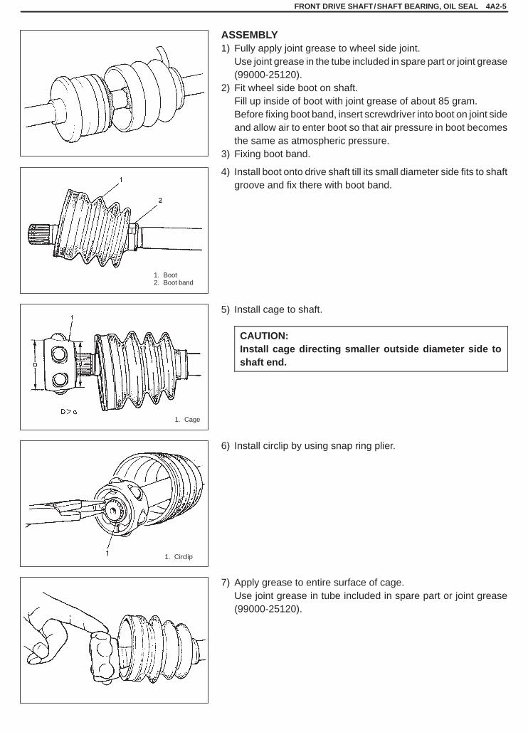
ASSEMBLY1) Fully apply joint grease to wheel side joint.
Use joint grease in the tube included in spare part or joint grease(99000-25120).
2) Fit wheel side boot on shaft.Fill up inside of boot with joint grease of about 85 gram.Before fixing boot band, insert screwdriver into boot on joint sideand allow air to enter boot so that air pressure in boot becomesthe same as atmospheric pressure.
3) Fixing boot band.
4) Install boot onto drive shaft till its small diameter side fits to shaftgroove and fix there with boot band.
5) Install cage to shaft.
CAUTION:Install cage directing smaller outside diameter side toshaft end.
6) Install circlip by using snap ring plier.
7) Apply grease to entire surface of cage.Use joint grease in tube included in spare part or joint grease(99000-25120).
SQHokubei(Supple)
1. Circlip
“ A”: Fill grease 85 g (3.0 oz)
4A2-6 FRONT DRIVE SHAFT/SHAFT BEARING, OIL SEAL
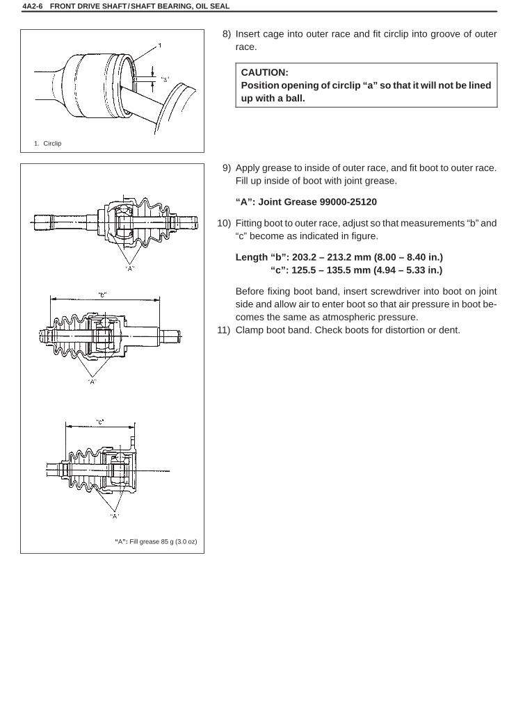
8) Insert cage into outer race and fit circlip into groove of outerrace.
CAUTION:Position opening of circlip “a” so that it will not be linedup with a ball.
9) Apply grease to inside of outer race, and fit boot to outer race.Fill up inside of boot with joint grease.
“A”: Joint Grease 99000-25120
10) Fitting boot to outer race, adjust so that measurements “b” and“c” become as indicated in figure.
Length “b”: 203.2 – 213.2 mm (8.00 – 8.40 in.)Length “c”: 125.5 – 135.5 mm (4.94 – 5.33 in.)
Before fixing boot band, insert screwdriver into boot on jointside and allow air to enter boot so that air pressure in boot be-comes the same as atmospheric pressure.
11) Clamp boot band. Check boots for distortion or dent.
SQHokubei(Supple)
1. Drive shaft oil seal
1. Drive shaft joint2. Oil seal3. Pipe4. Thrust washer
1. Drive shaft flange bolt and nut2. Axle shaft drive flange
2, (b)
FRONT DRIVE SHAFT/SHAFT BEARING, OIL SEAL 4A2-7
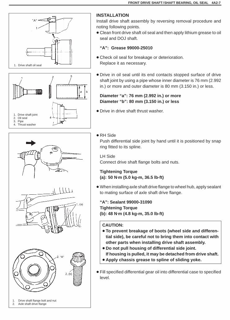
INSTALLATIONInstall drive shaft assembly by reversing removal procedure andnoting following points.�Clean front drive shaft oil seal and then apply lithium grease to oil
seal and DOJ shaft.
“A”: Grease 99000-25010
�Check oil seal for breakage or deterioration.Replace it as necessary.
�Drive in oil seal until its end contacts stopped surface of driveshaft joint by using a pipe whose inner diameter is 76 mm (2.992in.) or more and outer diameter is 80 mm (3.150 in.) or less.
Diameter “a”: 76 mm (2.992 in.) or moreDiameter “b”: 80 mm (3.150 in.) or less
�Drive in drive shaft thrust washer.
�RH SidePush differential side joint by hand until it is positioned by snapring fitted to its spline.
LH SideConnect drive shaft flange bolts and nuts.
Tightening Torque(a): 50 N.m (5.0 kg-m, 36.5 lb-ft)
�When installing axle shaft drive flange to wheel hub, apply sealantto mating surface of axle shaft drive flange.
“A”: Sealant 99000-31090Tightening Torque (b): 48 N.m (4.8 kg-m, 35.0 lb-ft)
CAUTION:� To prevent breakage of boots (wheel side and differen-
tial side), be careful not to bring them into contact withother parts when installing drive shaft assembly.
�Do not pull housing of differential side joint.If housing is pulled, it may be detached from drive shaft.
� Apply chassis grease to spline of sliding yoke.
� Fill specified differential gear oil into differential case to specifiedlevel.
SQHokubei(Supple)
BRAKES 5-1
5
SECTION 5
BRAKESWARNING:For vehicles equipped with Supplemental Restraint (Air Bag) System:� Service on and around the air bag system components or wiring must be performed only by an autho-
rized SUZUKI dealer. Refer to “Air Bag System Components and Wiring Location View” under “Gener-al Description” in air bag system section in order to confirm whether you are performing service onor near the air bag system components or wiring. Please observe all WARNINGS and “Service Precau-tions” under “On-Vehicle Service” in air bag system section before performing service on or aroundthe air bag system components or wiring. Failure to follow WARNINGS could result in unintentionalactivation of the system or could render the system inoperative. Either of these two conditions mayresult in severe injury.
� Technical service work must be started at least 90 seconds after the ignition switch is turned to the“LOCK” position and the negative cable is disconnected from the battery. Otherwise, the system maybe activated by reserve energy in the Sensing and Diagnostic Module (SDM).
NOTE:�When inspecting and servicing vehicle equipped with ABS, be sure to refer to section 5E1 first.� All brake fasteners are important attaching parts in that they could affect the performance of vital parts
and systems, and/or could result in major repair expense. They must be replaced with one of same partnumber or with an equivalent part if replacement becomes necessary. Do not use a replacement part oflesser quality or substitute design. Torque values must be used as specified during reassembly to as-sure proper retention of all parts. There is to be no welding as it may result in extensive damage andweakening of the metal.
� For the descriptions (items) not found in this section, refer to the same section of the Service Manualmentioned in FOREWORD of this manual.
CONTENTS
CHECK AND ADJUSTMENT 5- 2. . . . . . . . . . . . . . . . . . . . . . . . . . . . . . . . . . . . . . . . . . . . . . . . . . . . . . . . . . . . . . . . Fluid Pressure Test 5- 2. . . . . . . . . . . . . . . . . . . . . . . . . . . . . . . . . . . . . . . . . . . . . . . . . . . . . . . . . . . . . . . . . . . . . . .
TIGHTENING TORQUE SPECIFICATIONS 5- 3. . . . . . . . . . . . . . . . . . . . . . . . . . . . . . . . . . . . . . . . . . . . . . . . . . . .
SQHokubei(Supple)
1. Air bleeder plug2. Weight3. Attachment
2
“L”
5-2 BRAKES
CHECK AND ADJUSTMENT
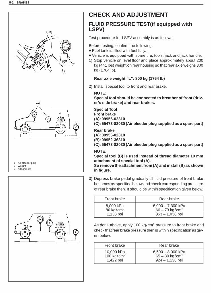
FLUID PRESSURE TEST(if equipped withLSPV)
Test procedure for LSPV assembly is as follows.
Before testing, confirm the following.� Fuel tank is filled with fuel fully.� Vehicle is equipped with spare tire, tools, jack and jack handle.1) Stop vehicle on level floor and place approximately about 200
kg (441 lbs) weight on rear housing so that rear axle weighs 800kg (1764 lb).
Rear axle weight “L”: 800 kg (1764 lb)
2) Install special tool to front and rear brake.
NOTE:Special tool should be connected to breather of front (driv-er’s side brake) and rear brakes.
Special ToolFront brake(A): 09956-02310(C): 55473-82030 (Air bleeder plug supplied as a spare part)
Rear brake(A): 09956-02310(B): 09952-36310(C): 55473-82030 (Air bleeder plug supplied as a spare part)
NOTE:Special tool (B) is used instead of thread diameter 10 mmattachment of special tool (A).So remove the attachment from (A) and install (B) as shownin figure.
3) Depress brake pedal gradually till fluid pressure of front brakebecomes as specified below and check corresponding pressureof rear brake then. It should be within specification given below.
Front brake Rear brake
8,000 kPa80 kg/cm2
6,000 – 7,300 kPa60 73 kg/cm280 kg/cm2
1,138 psi60 – 73 kg/cm2
853 – 1,038 psi
As done above, apply 100 kg/cm2 pressure to front brake andcheck that rear brake pressure then is within specification as giv-en below.
Front brake Rear brake
10,000 kPa100 kg/cm2
6,500 – 8,000 kPa65 – 80 kg/cm2100 kg/cm2
1,422 psi65 – 80 kg/cm2
924 – 1,138 psi
SQHokubei(Supple)
BRAKES 5-3
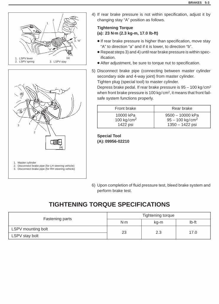
3. LSPV stay
1. Master cylinder2. Disconnect brake pipe (for LH steering vehicle)3. Disconnect brake pipe (for RH steering vehicle)
1. LSPV lever2. LSPV spring
3, “A”
21
3
2
(a)
“a”
“b”
4) If rear brake pressure is not within specification, adjust it bychanging stay “A” position as follows.
Tightening Torque(a): 23 N.m (2.3 kg-m, 17.0 lb-ft)
� If rear brake pressure is higher than specification, move stay“A” to direction “a” and if it is lower, to direction “b”.
�Repeat steps 3) and 4) until rear brake pressure is within spec-ification.
� After adjustment, be sure to torque nut to specification.
5) Disconnect brake pipe (connecting between master cylindersecondary side and 4-way joint) from master cylinder.Tighten plug (special tool) to master cylinder.Depress brake pedal. If rear brake pressure is 95 – 100 kg/cm2
when front brake pressure is 100 kg/cm2, it means that front fail-safe system functions properly.
Front brake Rear brake
10000 kPa100 kg/cm2
1422 psi
9500 – 10000 kPa95 – 100 kg/cm2
1350 – 1422 psi
Special Tool(A): 09956-02210
6) Upon completion of fluid pressure test, bleed brake system andperform brake test.
TIGHTENING TORQUE SPECIFICATIONS
Fastening partsTightening torque
Fastening artsN.m kg-m lb-ft
LSPV mounting bolt23 2 3 17 0
LSPV stay bolt23 2.3 17.0

SQHokubei(Supple)
5A
BRAKES PIPE/HOSE/MASTER CYLINDER 5A-1
SECTION 5A
BRAKES PIPE/HOSE/MASTER CYLINDERWARNING:For vehicles equipped with Supplemental Restraint (Air Bag) System:� Service on and around the air bag system components or wiring must be performed only by an autho-
rized SUZUKI dealer. Refer to “Air Bag System Components and Wiring Location View” under “Gener-al Description” in air bag system section in order to confirm whether you are performing service onor near the air bag system components or wiring. Please observe all WARNINGS and “Service Precau-tions” under “On-Vehicle Service” in air bag system section before performing service on or aroundthe air bag system components or wiring. Failure to follow WARNINGS could result in unintentionalactivation of the system or could render the system inoperative. Either of these two conditions mayresult in severe injury.
� Technical service work must be started at least 90 seconds after the ignition switch is turned to the“LOCK” position and the negative cable is disconnected from the battery. Otherwise, the system maybe activated by reserve energy in the Sensing and Diagnostic Module (SDM).
NOTE:� All brake fasteners are important attaching parts in that they could affect the performance of vital parts
and systems, and/or could result in major repair expense. They must be replaced with one of same partnumber or with an equivalent part if replacement becomes necessary. Do not use a replacement part oflesser quality or substitute design. Torque values must be used as specified during reassembly to as-sure proper retention of all parts. There is to be no welding as it may result in extensive damage andweakening of the metal.
� For the descriptions (items) not found in this section, refer to the same section of the Service Manualmentioned in FOREWORD of this manual.
CONTENTS
ON-VEHICLE SERVICE 5A- 2. . . . . . . . . . . . . . . . . . . . . . . . . . . . . . . . . . . . . . . . . . . . . . . . . . . . . . . . . . . . . . . . . . . . LSPV (Load Sensing Proportioning Valve) Assembly 5A- 2. . . . . . . . . . . . . . . . . . . . . . . . . . . . . . . . . . . . . . . . . .
TIGHTENING TORQUE SPECIFICATIONS 5A- 4. . . . . . . . . . . . . . . . . . . . . . . . . . . . . . . . . . . . . . . . . . . . . . . . . . . .
SQHokubei(Supple)
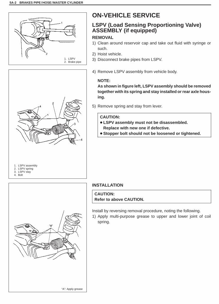
1. LSPV2. Brake pipe
1. LSPV assembly2. LSPV spring3. LSPV stay4. Bolt
“A”: Apply grease
5A-2 BRAKES PIPE/HOSE/MASTER CYLINDER
ON-VEHICLE SERVICE
LSPV (Load Sensing Proportioning Valve) ASSEMBLY (if equipped)REMOVAL1) Clean around reservoir cap and take out fluid with syringe or
such.2) Hoist vehicle.3) Disconnect brake pipes from LSPV.
4) Remove LSPV assembly from vehicle body.
NOTE:As shown in figure left, LSPV assembly should be removedtogether with its spring and stay installed or rear axle hous-ing.
5) Remove spring and stay from lever.
CAUTION:� LSPV assembly must not be disassembled.
Replace with new one if defective.� Stopper bolt should not be loosened or tightened.
INSTALLATION
CAUTION:Refer to above CAUTION.
Install by reversing removal procedure, noting the following.1) Apply multi-purpose grease to upper and lower joint of coil
spring.

SQHokubei(Supple)
BRAKES PIPE/HOSE/MASTER CYLINDER 5A-3
1. LSPV stay bolt2. LSPV bolt3. Brake pipe flare nut4. Air bleeding plug
1, (a)
1. LSPV stay bolt2. LSPV stay
2) Torque each bolt and nut to specification as indicated respec-tively in figure left.
Tightening Torque(a): 23 N.m (2.3 kg-m, 17.0 lb-ft)(b): 16 N.m (1.6 kg-m, 11.5 lb-ft) (brake flare nut)(c): 7.5 N.m (0.75 kg-m, 9.0 lb-ft) (bleeder plug)
3) Upon completion of installation, fill reservoir tank with specifiedfluid and bleed air from brake system.
NOTE:Make sure to bleed air from LSPV bleeder without failure.
4) After bleeding air, check that LSPV is installed properly, referringto following INSPECTION & ADJUSTMENT.
INSPECTION & ADJUSTMENTConfirm the following before inspection and adjustment.� Fuel tank is filled with fuel fully.� Vehicle is equipped with spare tire, tools, jack and jack handle.� Vehicle is free from any other load.
With vehicle in above conditions;1) Place it on level floor.2) Push up LSPV lever with finger till it stops and measure length
of coil spring (“L” in below figure) as it is pulled.3) Spring length “L” should be the value specified below.
Spring length (between spring ends)“L”: 103 mm (4.06 in.)
4) If it isn’t, adjust it to specification by changing stay positions asshown in left figure. After adjustment, tighten bolt to specifiedtorque.For details, refer to left figure.
Tightening Torque(a): 23 N.m (2.3 kg-m, 17.0 lb-ft)
NOTE:Check to make sure that LSPV body and brake pipe jointsare free from fluid leakage. Replace defective parts, if any.

SQHokubei(Supple)
5A-4 BRAKES PIPE/HOSE/MASTER CYLINDER
TIGHTENING TORQUE SPECIFICATIONS
Fastening partsTightening torque
Fastening artsN.m kg-m lb-ft
LSPV mounting bolt23 2 3 17 0
LSPV stay bolt23 2.3 17.0

SQHokubei(Supple)
6
ENGINE GENERAL INFORMATION (G16 /J20/H25 ENGINE) 6-1
SECTION 6
ENGINE(G16/J20/H25 ENGINE)
WARNING:For vehicles equipped with Supplemental Restraint (Air Bag) System:� Service on and around the air bag system components or wiring must be performed only by an autho-
rized SUZUKI dealer. Refer to “Air Bag System Components and Wiring Location View” under “Gener-al Description” in air bag system section in order to confirm whether you are performing service onor near the air bag system components or wiring. Please observe all WARNINGS and “Service Precau-tions” under “On-Vehicle Service” in air bag system section before performing service on or aroundthe air bag system components or wiring. Failure to follow WARNINGS could result in unintentionalactivation of the system or could render the system inoperative. Either of these two conditions mayresult in severe injury.
� Technical service work must be started at least 90 seconds after the ignition switch is turned to the“LOCK” position and the negative cable is disconnected from the battery. Otherwise, the system maybe activated by reserve energy in the Sensing and Diagnostic Module (SDM).
NOTE:For the description (items) not found in this section, refer to the same section of the Service Manual men-tioned in FOREWORD of this manual.
CONTENTS
GENERAL INFORMATION 6- 2. . . . . . . . . . . . . . . . . . . . . . . . . . . . . . . . . . . . . . . . . . . . . . . . . . . . . . . . . . . . . . . . . . General Information on Engine Service 6- 2. . . . . . . . . . . . . . . . . . . . . . . . . . . . . . . . . . . . . . . . . . . . . . . . . . . . . .
Fuel pressure relief procedure 6- 2. . . . . . . . . . . . . . . . . . . . . . . . . . . . . . . . . . . . . . . . . . . . . . . . . . . . . . . . . . . .

SQHokubei(Supple)
1. Fuel pump relay2. Junction (Fuse) box
1. Fuel pump relay2. Junction (Fuse) box
Left hand steering vehicle
Right hand steering vehicle
6-2 ENGINE GENERAL INFORMATION (G16 /J20/H25 ENGINE)
GENERAL INFORMATION
GENERAL INFORMATION ON ENGINESERVICEFUEL PRESSURE RELIEF PROCEDURE
CAUTION:This work must not be done when engine is hot. If done so,it may cause adverse effect to catalyst.
After making sure that engine is cold, relief fuel pressure as follows.1) Place transmission gear shift lever in “Neutral” (shift selector le-
ver to “P” range for A/T vehicle), set parking brake, and blockdrive wheels.
2) Remove fuel pump relay from connector.3) Remove fuel filler cap to release fuel vapor pressure in fuel tank
and then reinstall it.4) Start engine and run it till it stops for lack of fuel. Repeat cranking
engine 2 – 3 times of about 3 seconds each time to dissipate fuelpressure in lines. Fuel connections are now safe for servicing.
5) Upon completion of servicing, install fuel pump relay to connec-tor.

SQHokubei(Supple)
6E1
ENGINE AND EMISSION CONTROL SYSTEM (G16 /J20 ENGINE) 6E1-1
SECTION 6E1
ENGINE AND EMISSION CONTROL SYSTEM(SEQUENTIAL MULTIPORT FUEL INJECTION FOR
G16/J20 ENGINE)WARNING:For vehicles equipped with Supplemental Restraint (Air Bag) System:� Service on and around the air bag system components or wiring must be performed only by an autho-
rized SUZUKI dealer. Refer to “Air Bag System Components and Wiring Location View” under “Gener-al Description” in air bag system section in order to confirm whether you are performing service onor near the air bag system components or wiring. Please observe all WARNINGS and “Service Precau-tions” under “On-Vehicle Service” in air bag system section before performing service on or aroundthe air bag system components or wiring. Failure to follow WARNINGS could result in unintentionalactivation of the system or could render the system inoperative. Either of these two conditions mayresult in severe injury.
� Technical service work must be started at least 90 seconds after the ignition switch is turned to the“LOCK” position and the negative cable is disconnected from the battery. Otherwise, the system maybe activated by reserve energy in the Sensing and Diagnostic Module (SDM).
NOTE:� For the descriptions (items) not found in this section, refer to the same section of the Service Manual
mentioned in FOREWORD of this manual.�Whether the following systems (parts) are used in the particular vehicle or not depends on specifica-
tions. Be sure to bear this in mind when performing service work.– EGR valve– Heated oxygen sensor or CO adjusting resistor– Three way catalytic converter
CONTENTS
GENERAL DESCRIPTION 6E1- 2. . . . . . . . . . . . . . . . . . . . . . . . . . . . . . . . . . . . . . . . . . . . . . . . . . . . . . . . . . . . . . . . . . ELECTRONIC CONTROL SYSTEM 6E1- 2. . . . . . . . . . . . . . . . . . . . . . . . . . . . . . . . . . . . . . . . . . . . . . . . . . . . . . . . . .
DIAGNOSIS 6E1- 4. . . . . . . . . . . . . . . . . . . . . . . . . . . . . . . . . . . . . . . . . . . . . . . . . . . . . . . . . . . . . . . . . . . . . . . . . . . . . . . On-Board Diagnostic System 6E1- 4. . . . . . . . . . . . . . . . . . . . . . . . . . . . . . . . . . . . . . . . . . . . . . . . . . . . . . . . . . . . . . Precautions in Diagnosing Troubles 6E1- 4. . . . . . . . . . . . . . . . . . . . . . . . . . . . . . . . . . . . . . . . . . . . . . . . . . . . . . . . . B-1 Fuel Pump Circuit Check 6E1- 5. . . . . . . . . . . . . . . . . . . . . . . . . . . . . . . . . . . . . . . . . . . . . . . . . . . . . . . . . . . . . . Inspection of PCM (ECM) and Its Circuit 6E1- 6. . . . . . . . . . . . . . . . . . . . . . . . . . . . . . . . . . . . . . . . . . . . . . . . . . . . .
ON-VEHICLE SERVICE 6E1- 9. . . . . . . . . . . . . . . . . . . . . . . . . . . . . . . . . . . . . . . . . . . . . . . . . . . . . . . . . . . . . . . . . . . . FUEL DELIVERY SYSTEM 6E1- 9. . . . . . . . . . . . . . . . . . . . . . . . . . . . . . . . . . . . . . . . . . . . . . . . . . . . . . . . . . . . . . . . . .
Fuel Injector (Inspection) 6E1- 9. . . . . . . . . . . . . . . . . . . . . . . . . . . . . . . . . . . . . . . . . . . . . . . . . . . . . . . . . . . . . . . . . . ELECTRONIC CONTROL SYSTEM 6E1-11. . . . . . . . . . . . . . . . . . . . . . . . . . . . . . . . . . . . . . . . . . . . . . . . . . . . . . . . . .
Main Relay (Inspection) 6E1-11. . . . . . . . . . . . . . . . . . . . . . . . . . . . . . . . . . . . . . . . . . . . . . . . . . . . . . . . . . . . . . . . . . . Fuel Pump Relay (Inspection) 6E1-12. . . . . . . . . . . . . . . . . . . . . . . . . . . . . . . . . . . . . . . . . . . . . . . . . . . . . . . . . . . . . .
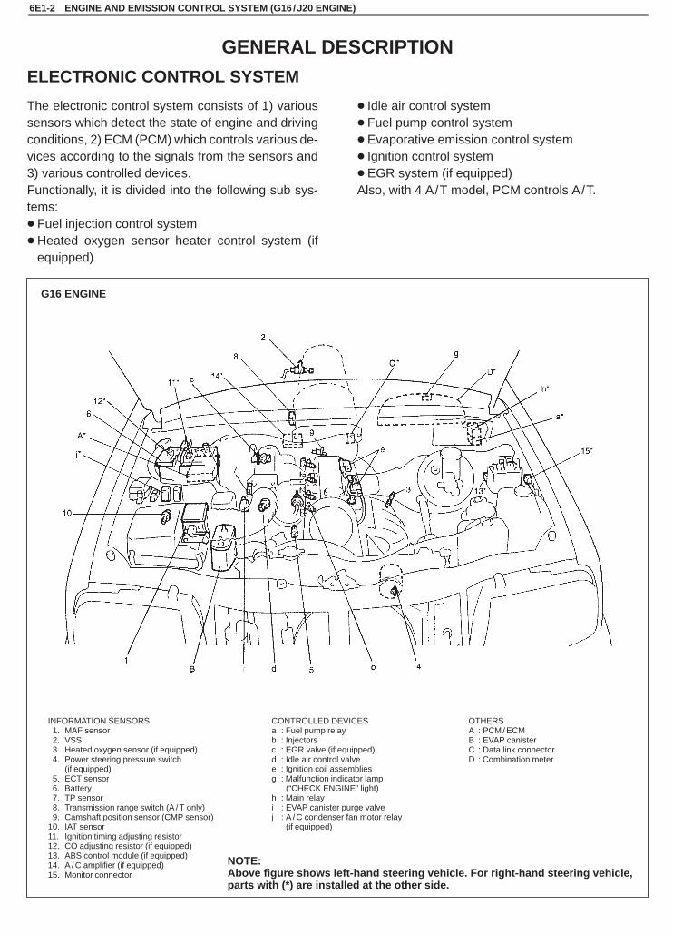
SQHokubei(Supple)
INFORMATION SENSORS1. MAF sensor2. VSS3. Heated oxygen sensor (if equipped)4. Power steering pressure switch
(if equipped)5. ECT sensor6. Battery7. TP sensor8. Transmission range switch (A / T only)9. Camshaft position sensor (CMP sensor)
10. IAT sensor11. Ignition timing adjusting resistor12. CO adjusting resistor (if equipped)13. ABS control module (if equipped)14. A / C amplifier (if equipped)15. Monitor connector
CONTROLLED DEVICESa : Fuel pump relayb : Injectorsc : EGR valve (if equipped)d : Idle air control valvee : Ignition coil assembliesg : Malfunction indicator lamp
: (“CHECK ENGINE” light)h : Main relayi : EVAP canister purge valvej : A / C condenser fan motor relay
: (if equipped)
OTHERSA : PCM / ECMB : EVAP canisterC : Data link connectorD : Combination meter
NOTE:Above figure shows left-hand steering vehicle. For right-hand steering vehicle,parts with (*) are installed at the other side.
G16 ENGINE
6E1-2 ENGINE AND EMISSION CONTROL SYSTEM (G16 /J20 ENGINE)
The electronic control system consists of 1) varioussensors which detect the state of engine and drivingconditions, 2) ECM (PCM) which controls various de-vices according to the signals from the sensors and3) various controlled devices.Functionally, it is divided into the following sub sys-tems:� Fuel injection control system�Heated oxygen sensor heater control system (if
equipped)
� Idle air control system� Fuel pump control system� Evaporative emission control system� Ignition control system� EGR system (if equipped)Also, with 4 A/T model, PCM controls A/T.
GENERAL DESCRIPTION
ELECTRONIC CONTROL SYSTEM

SQHokubei(Supple)
J20 ENGINE
INFORMATION SENSORS1. IAT sensor2. MAF sensor3. Power steering pressure switch
(if equipped)4. Heated oxygen sensor (if equipped)5. Monitor connector6. ABS control module (if equipped)7. Camshaft position sensor (CMP sensor)8. ECT sensor9. TP sensor
10. Battery11. CO adjusting resistor (if equipped)
CONTROLLED DEVICESa : Idle air control valveb : A / C condenser fan motor relay
: (if equipped)c : EVAP canister purge valved : Ignition coil assembliese : Main relayf : Fuel pump relayg : Malfunction indicator lamp
: (“CHECK ENGINE” light)h : Injectorsi : EGR valve (if equipped)
OTHERSA : ECM (PCM)B : EVAP canisterC : Data link connectorD : Combination meter
NOTE:Above figure shows left-hand steering vehicle. For right-hand steering vehicle,parts with (*) are installed at the other side.
ENGINE AND EMISSION CONTROL SYSTEM (G16 /J20 ENGINE) 6E1-3

SQHokubei(Supple)
6E1-4 ENGINE AND EMISSION CONTROL SYSTEM (G16 /J20 ENGINE)
DIAGNOSIS
The engine and emission control system in this vehicle are con-trolled by ECM/PCM. ECM/PCM has an On-Board Diagnostic sys-tem which detects a malfunction in this system.When diagnosing troubles, be sure to have full understanding of theoutline of “On-Board Diagnostic System” and each item in “Precau-tion in Diagnosing Trouble” and execute diagnosis according to“Engine Diagnostic Flow Table” in Section 6.
ON-BOARD DIAGNOSTIC SYSTEMECM/PCM performs on-board diagnosis (self-diagnosis) on thesystem and operates “CHECK ENGINE” lamp (malfunction indica-tor lamp) as follows.�Malfunction indicator lamp (“CHECK ENGINE” light) lights when
the ignition switch is turned ON (but the engine at stop) regardlessof the condition of Engine and emission control system. This isonly to check the malfunction indicator lamp (“CHECK ENGINE”light) bulb and its circuit.
� If the areas monitored by ECM/PCM is free from any trouble afterthe engine start (while engine is running), malfunction indicatorlamp (“CHECK ENGINE” light) turns OFF.
�When ECM/PCM detects a trouble which has occurred in theareas, it makes malfunction indicator lamp (“CHECK ENGINE”light) turn ON while the engine is running to warn the driver of suchoccurrence of trouble and at the same time it stores the exacttrouble area in ECM/PCM back-up memory.
PRECAUTIONS IN DIAGNOSING TROUBLES� Before identifying diagnostic trouble code, don’t disconnect cou-
plers from ECM/PCM, battery cable from battery, ECM/PCMground wire harness from engine. Such disconnection will erasememorized trouble in ECM/PCM memory.
� Be sure to read “Precautions for Electrical Circuit Service” in Sec-tion 0A before inspection and observe what is written there.
� ECM/PCM replacementWhen substituting a known-good ECM/PCM, check for followingconditions. Neglecting this check may cause damage to known-good ECM/PCM.– Resistance value of all relays, actuators is as specified re-
spectively.– TP sensor and fuel tank pressure sensor (if equipped) are in
good condition and none of power circuits of these sensors isshorted to ground.
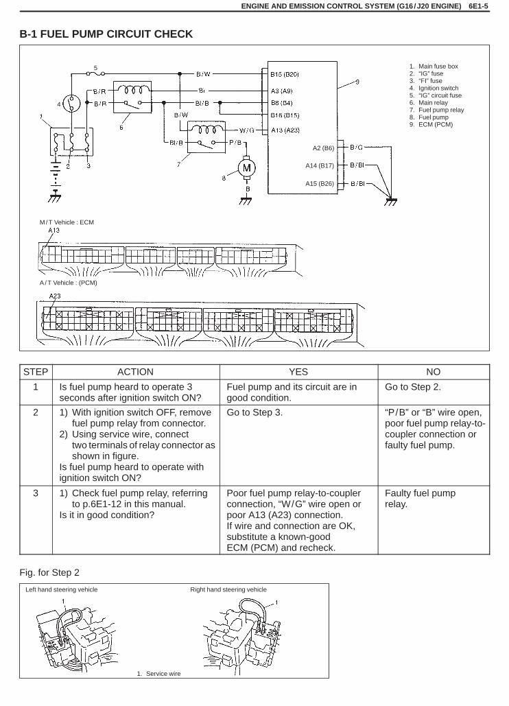
SQHokubei(Supple)
ENGINE AND EMISSION CONTROL SYSTEM (G16 /J20 ENGINE) 6E1-5
1. Main fuse box2. “IG” fuse3. “FI” fuse4. Ignition switch5. “IG” circuit fuse6. Main relay7. Fuel pump relay8. Fuel pump9. ECM (PCM)
M / T Vehicle : ECM
A / T Vehicle : (PCM)
1. Service wire
Left hand steering vehicle Right hand steering vehicle
A15 (B26)
A2 (B6)
A14 (B17)
4
5
B-1 FUEL PUMP CIRCUIT CHECK
STEP ACTION YES NO
1 Is fuel pump heard to operate 3seconds after ignition switch ON?
Fuel pump and its circuit are ingood condition.
Go to Step 2.
2 1) With ignition switch OFF, removefuel pump relay from connector.
2) Using service wire, connecttwo terminals of relay connector asshown in figure.
Is fuel pump heard to operate withignition switch ON?
Go to Step 3. “P/B” or “B” wire open,poor fuel pump relay-to-coupler connection orfaulty fuel pump.
3 1) Check fuel pump relay, referringto p.6E1-12 in this manual.
Is it in good condition?
Poor fuel pump relay-to-couplerconnection, “W/G” wire open orpoor A13 (A23) connection.If wire and connection are OK,substitute a known-goodECM (PCM) and recheck.
Faulty fuel pumprelay.
Fig. for Step 2
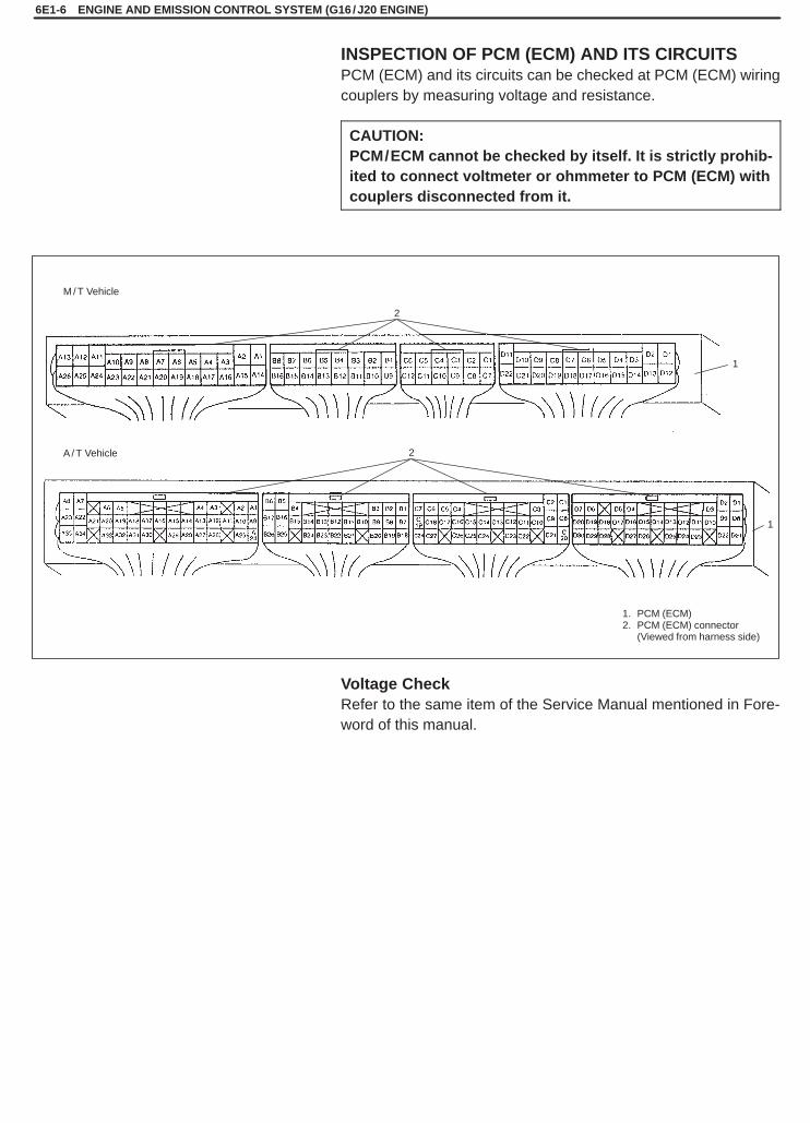
SQHokubei(Supple)
M / T Vehicle
A / T Vehicle
1. PCM (ECM)2. PCM (ECM) connector
(Viewed from harness side)
2
2
1
1
6E1-6 ENGINE AND EMISSION CONTROL SYSTEM (G16 /J20 ENGINE)
INSPECTION OF PCM (ECM) AND ITS CIRCUITSPCM (ECM) and its circuits can be checked at PCM (ECM) wiringcouplers by measuring voltage and resistance.
CAUTION:PCM/ECM cannot be checked by itself. It is strictly prohib-ited to connect voltmeter or ohmmeter to PCM (ECM) withcouplers disconnected from it.
Voltage CheckRefer to the same item of the Service Manual mentioned in Fore-word of this manual.

SQHokubei(Supple)
ENGINE AND EMISSION CONTROL SYSTEM (G16 /J20 ENGINE) 6E1-7
1. ECM/ PCM coupler disconnected2. Ohmmeter
Resistance Check1) Disconnect couplers from ECM/PCM with ignition switch OFF.
CAUTION:Never touch terminals of ECM/PCM itself or connectvoltmeter or ohmmeter.
2) Check resistance between each pair of terminals of discon-nected couplers as listed in following table.
CAUTION:� Be sure to connect ohmmeter probe from wire harness
side of coupler.� Be sure to turn OFF ignition switch for this check.� Resistance in table represents that when parts temper-
ature is 20 �C (68�F).
M/T VEHICLE
TERMINALS CIRCUIT STANDARD RESISTANCE CONDITION
A3 – A1 Main relay 79 – 95 �
A13 – B15 Fuel pump relay 79 – 95 �
A26 – B15 A/C fan motor relay (if equipped) 75 – 110 �Battery disconnected andignition switch ON
D1 – B8 Fuel injector No.213 16 �
D2 – B8 Fuel injector No.113 – 16 �
D3 – B8 IAC valve (stepper motor coil 2)35 43 �
D4 – B8 IAC valve (stepper motor coil 1)35 – 43 �
D7 – B8EGR valve (stepper motor coil 2,if equipped)
20 24 �
D8 – B8EGR valve (stepper motor coil 1,if equipped)
20 – 24 �
D9 – B15 Heater of HO2S (if equipped) 11.7 – 14.3 �
D12 – B8 Fuel injector No.413 16 �
D13 – B8 Fuel injector No.313 – 16 �
D14 – B8 IAC valve (stepper motor coil 4)35 43 �
D15 – B8 IAC valve (stepper motor coil 3)35 – 43 �
D18 – B8EGR valve (stepper motor coil 4,if equipped)
20 24 �
D19 – B8EGR valve (stepper motor coil 3,if equipped)
20 – 24 �
D20 – B8 EVAP canister purge valve 28 – 35 �
A2 – Body ground Ground Continuity
A14 – Body ground Ground Continuity
A15 – Body ground Ground Continuity

SQHokubei(Supple)
6E1-8 ENGINE AND EMISSION CONTROL SYSTEM (G16 /J20 ENGINE)
A/T VEHICLE
TERMINALS CIRCUIT STANDARD RESISTANCE CONDITION
A9 – A2 Main relay 79 – 95 �
A22 – B20 A/C fan motor relay (if equipped) 75 – 110 �Battery disconnected andignition switch ON
A23 – B20 Fuel pump relay 79 – 95 �
B6 – Body ground Ground Continuity
B17 – Body ground Ground Continuity
B26 – Body ground Ground Continuity
C1 – Body ground Shift solenoid B
C2 – Body ground Shift solenoid A 11 – 15 �
C8 – Body ground TCC solenoid
D1 – B4 Fuel injector No.213 16 �
D2 – B4 Fuel injector No.113 – 16 �
D3 – B4 IAC valve (stepper motor coil 1) 35 – 43 �
D4 – B20 Heater of HO2S (if equipped) 11.7 – 14.3 �
D8 – B4 Fuel injector No.413 16 �
D9 – B4 Fuel injector No.313 – 16 �
D10 – B4 IAC valve (stepper motor coil 4)
D11 – B4 IAC valve (stepper motor coil 3) 35 – 43 �
D12 – B4 IAC valve (stepper motor coil 2)
D13 – B4EGR valve (stepper motor coil 4,if equipped)
D14 – B4EGR valve (stepper motor coil 3,if equipped)
20 24 �
D15 – B4EGR valve (stepper motor coil 2,if equipped)
20 – 24 �
D16 – B4EGR valve (stepper motor coil 1,if equipped)
D17 – B4 EVAP canister purge valve 28 – 35 �

SQHokubei(Supple)
1. Fuel feed pipe and hose2. Fuel injector3. Fuel pressure regulator4. Fuel return pipe
3. Keep as far apartas possible
1. Injector2. Battery
1. Fuel pump relayconnector
2. Service wire3. Junction (Fuse) box
Left handsteering vehicle
Right handsteering vehicle
ENGINE AND EMISSION CONTROL SYSTEM (G16 /J20 ENGINE) 6E1-9
ON-VEHICLE SERVICEFUEL DELIVERY SYSTEMFUEL INJECTORInspection
WARNING:As fuel is injected in this inspection, perform in a well venti-lated area and away from open flames.Use special care to prevent sparking when connecting anddisconnecting test lead to and from battery.
1) Install injector and fuel pressure regulator to special tool (injec-tor checking tool).
Special Tool(A): 09912-58421
2) Connect special tools (hoses and attachment) to hose and pipeof vehicle.
Special Tool(B): 09912-58431
3) Connect special tool (test lead) to injector.
Special Tool(D): 09930-88530
4) Install suitable vinyl tube onto injector nozzle to prevent fuel fromsplashing out when injecting.
5) Put graduated cylinder under injector as shown.6) Remove fuel pump relay.7) To operate fuel pump and apply fuel pressure to injector, using
wire harness as thick as the one used for fuel pump circuit, con-nect two terminals of relay connector as shown in figure.
CAUTION:Check to make sure that connection is made betweencorrect terminals. Wrong connection can cause damageto PCM (ECM), wire harness, etc.
Turn ignition switch ON.8) Apply battery voltage to injector for 15 seconds and measure in-
jected fuel volume with graduated cylinder.Test each injector two or three times.If not within specification, replace injector.
Injected fuel volume:42 – 52 cc/15 sec. (1.42/1.48 – 1.75/1.83 US/lmp. oz/15 sec.)for G16 engine.55 – 62 cc/15 sec. (1.94/2.09 – 2.18/2.36 US/lmp. oz/15 sec.)for J20 engine.
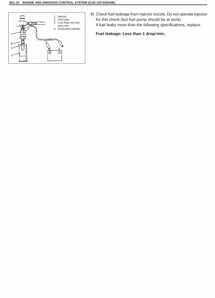
SQHokubei(Supple)
6E1-10 ENGINE AND EMISSION CONTROL SYSTEM (G16 /J20 ENGINE)
1. Injector2. Vinyl tube3. Less than one fuel
drop / min4. Graduated cylinder
9) Check fuel leakage from injector nozzle. Do not operate injectorfor this check (but fuel pump should be at work).If fuel leaks more than the following specifications, replace.
Fuel leakage: Less than 1 drop/min.
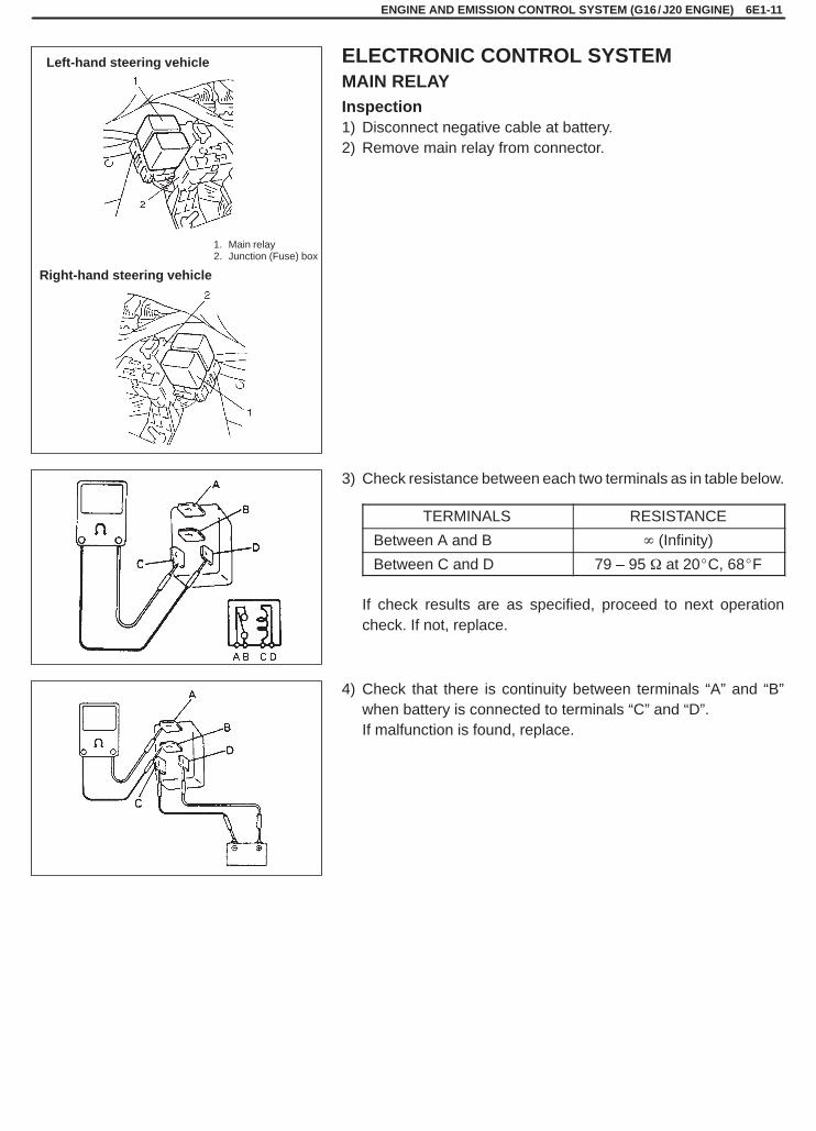
SQHokubei(Supple)
1. Main relay2. Junction (Fuse) box
Left-hand steering vehicle
Right-hand steering vehicle
ENGINE AND EMISSION CONTROL SYSTEM (G16 /J20 ENGINE) 6E1-11
ELECTRONIC CONTROL SYSTEMMAIN RELAYInspection1) Disconnect negative cable at battery.2) Remove main relay from connector.
3) Check resistance between each two terminals as in table below.
TERMINALS RESISTANCE
Between A and B � (Infinity)
Between C and D 79 – 95 � at 20�C, 68�F
If check results are as specified, proceed to next operationcheck. If not, replace.
4) Check that there is continuity between terminals “A” and “B”when battery is connected to terminals “C” and “D”.If malfunction is found, replace.

SQHokubei(Supple)
6E1-12 ENGINE AND EMISSION CONTROL SYSTEM (G16 /J20 ENGINE)
1. Fuel pump relay2. Junction (Fuse) box
Left-hand steering vehicle
Right-hand steering vehicle
FUEL PUMP RELAYInspection1) Disconnect negative cable at battery.2) Remove fuel pump relay from connector.3) Structure of fuel pump relay is the same as that of main relay.
Check its resistance and operation using the same procedure asthat for main relay.If malfunction is found, replace.
SQHokubei(Supple)
6H
CHARGING SYSTEM 6H-1
SECTION 6H
CHARGING SYSTEMWARNING:For vehicles equipped with Supplemental Restraint (Air Bag) System:� Service on and around the air bag system components or wiring must be performed only by an autho-
rized SUZUKI dealer. Refer to “Air Bag System Components and Wiring Location View” under “Gener-al Description” in air bag system section in order to confirm whether you are performing service onor near the air bag system components or wiring. Please observe all WARNINGS and “Service Precau-tions” under “On-Vehicle Service” in air bag system section before performing service on or aroundthe air bag system components or wiring. Failure to follow WARNINGS could result in unintentionalactivation of the system or could render the system inoperative. Either of these two conditions mayresult in severe injury.
� Technical service work must be started at least 90 seconds after the ignition switch is turned to the“LOCK” position and the negative cable is disconnected from the battery. Otherwise, the system maybe activated by reserve energy in the Sensing and Diagnostic Module (SDM).
NOTE:� For the descriptions (items) not found in this section, refer to the same section of the Service Manual
mentioned in FOREWORD of this manual.� As regards items for 70A type generator which are not found in this section of this manual, refer to each
item applicable to 60A type generator described in the same section of the Service Manual mentionedin FOREWORD of this manual.
CONTENTS
GENERAL DESCRIPTION 6H- 2. . . . . . . . . . . . . . . . . . . . . . . . . . . . . . . . . . . . . . . . . . . . . . . . . . . . . . . . . . . . . . . . . . GENERATOR [70 A type] 6H- 2. . . . . . . . . . . . . . . . . . . . . . . . . . . . . . . . . . . . . . . . . . . . . . . . . . . . . . . . . . . . . . . . . .
SPECIFICATIONS 6H- 3. . . . . . . . . . . . . . . . . . . . . . . . . . . . . . . . . . . . . . . . . . . . . . . . . . . . . . . . . . . . . . . . . . . . . . . . . BATTERY 6H- 3. . . . . . . . . . . . . . . . . . . . . . . . . . . . . . . . . . . . . . . . . . . . . . . . . . . . . . . . . . . . . . . . . . . . . . . . . . . . . . . GENERATOR 6H- 3. . . . . . . . . . . . . . . . . . . . . . . . . . . . . . . . . . . . . . . . . . . . . . . . . . . . . . . . . . . . . . . . . . . . . . . . . . . .
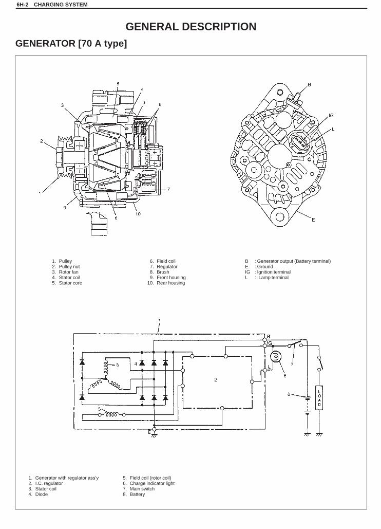
SQHokubei(Supple)
1. Pulley2. Pulley nut3. Rotor fan4. Stator coil5. Stator core
6. Field coil7. Regulator8. Brush9. Front housing
10. Rear housing
B : Generator output (Battery terminal)E : GroundIG : Ignition terminalL : Lamp terminal
1. Generator with regulator ass’y2. I.C. regulator3. Stator coil4. Diode
5. Field coil (rotor coil)6. Charge indicator light7. Main switch8. Battery
6H-2 CHARGING SYSTEM
GENERAL DESCRIPTION
GENERATOR [70 A type]

SQHokubei(Supple)
CHARGING SYSTEM 6H-3
SPECIFICATIONS
BATTERY
NOTE:The battery used in each vehicle is one of the following three types, depending on specification.
Group GP26R GP85R
Cold Cranking Ampere (A) 390 550
Load Test (A) 190 220
Rated Capacity (AH/5HR, 12 Volts) 36 48
GENERATOR
NOTE:The generator used in each vehicle is one of the following two types, depending on specification.
Type 60 A type 70 A type
Rated voltage 12 V
Nominal output 60 A 70 A
Permissible max. speed 18000 r/min.
No-load speed 1300 r/min (rpm)
Setting voltage 14.4 to 15.0 V
Permissible ambienttemperature
–30 to 90�C (–22 to 194�F)
Polarity Negative ground
Rotation Clockwise viewed from pulley side
SQHokubei(Supple)
7B1
AUTOMATIC TRANSMISSION (4 A /T) 7B1-1
SECTION 7B1
AUTOMATIC TRANSMISSION(4 A/T)
WARNING:For vehicles equipped with Supplemental Restraint (Air Bag) System:� Service on and around the air bag system components or wiring must be performed only by an autho-
rized SUZUKI dealer. Refer to “Air Bag System Components and Wiring Location View” under “Gener-al Description” in air bag system section in order to confirm whether you are performing service onor near the air bag system components or wiring. Please observe all WARNINGS and “Service Precau-tions” under “On-Vehicle Service” in air bag system section before performing service on or aroundthe air bag system components or wiring. Failure to follow WARNINGS could result in unintentionalactivation of the system or could render the system inoperative. Either of these two conditions mayresult in severe injury.
� Technical service work must be started at least 90 seconds after the ignition switch is turned to the“LOCK” position and the negative cable is disconnected from the battery. Otherwise, the system maybe activated by reserve energy in the Sensing and Diagnostic Module (SDM).
NOTE:For the descriptions (items) not found in this section, refer to the same section of the Service Manual men-tioned in FOREWORD of this manual.
CONTENTS
ON-VEHICLE SERVICE 7B1- 2. . . . . . . . . . . . . . . . . . . . . . . . . . . . . . . . . . . . . . . . . . . . . . . . . . . . . . . . . . . . . . . . . . . . Manual Selector Assembly (For LH Vehicle) 7B1- 2. . . . . . . . . . . . . . . . . . . . . . . . . . . . . . . . . . . . . . . . . . . . . . . . . . Key Interlock Cable (If Equipped) 7B1- 3. . . . . . . . . . . . . . . . . . . . . . . . . . . . . . . . . . . . . . . . . . . . . . . . . . . . . . . . . . .
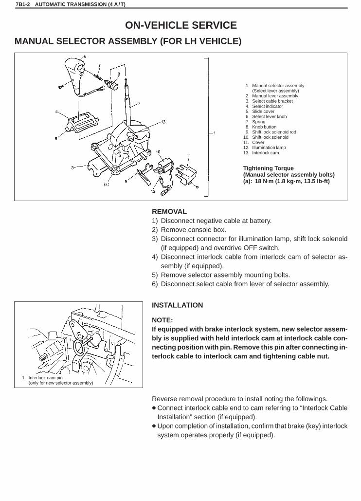
SQHokubei(Supple)
1. Manual selector assembly (Select lever assembly)
2. Manual lever assembly3. Select cable bracket4. Select indicator5. Slide cover6. Select lever knob7. Spring8. Knob button9. Shift lock solenoid rod
10. Shift lock solenoid11. Cover12. Illumination lamp13. Interlock cam
1. Interlock cam pin (only for new selector assembly)
Tightening Torque(Manual selector assembly bolts)(a): 18 N.m (1.8 kg-m, 13.5 lb-ft)
7B1-2 AUTOMATIC TRANSMISSION (4 A /T)
ON-VEHICLE SERVICE
MANUAL SELECTOR ASSEMBLY (FOR LH VEHICLE)
REMOVAL1) Disconnect negative cable at battery.2) Remove console box.3) Disconnect connector for illumination lamp, shift lock solenoid
(if equipped) and overdrive OFF switch.4) Disconnect interlock cable from interlock cam of selector as-
sembly (if equipped).5) Remove selector assembly mounting bolts.6) Disconnect select cable from lever of selector assembly.
INSTALLATION
NOTE:If equipped with brake interlock system, new selector assem-bly is supplied with held interlock cam at interlock cable con-necting position with pin. Remove this pin after connecting in-terlock cable to interlock cam and tightening cable nut.
Reverse removal procedure to install noting the followings.�Connect interlock cable end to cam referring to “Interlock Cable
Installation” section (if equipped).�Upon completion of installation, confirm that brake (key) interlock
system operates properly (if equipped).

SQHokubei(Supple)
AUTOMATIC TRANSMISSION (4 A /T) 7B1-3
Ignition switch side
1. Ignition switch ass’y2. Clamp screw3. Interlock cable
Select lever side
1. Inner end of interlock cable2. Interlock cam3. Stud bolt
4. Cam boss5. Claw
1. Ignition switch ass’y2. Clamp screw3. Outer end
KEY INTERLOCK CABLE (IF EQUIPPED)
NOTE:Don’t bend interlock cable excessively when removing andinstalling it, or system will not operate correctly.
Removal1) Disconnect negative (–) cable from battery.2) If equipped with air bag system, disable air bag system.
Refer to “Disabling Air bag System” in Section 10B.3) Remove steering column hole cover.4) Tilt steering column if steering column is adjustable.
If no adjustable, loosen steering column bolts.5) Remove steering column cover.
6) Remove interlock cable clamp screw located at ignition switchass’y.
7) Remove disconnect interlock cable inner end.(Ignition switch side.)
8) With console box removed, take out interlock cable by looseninglock nuts.
9) Detach cable end from interlock cam while pressing claws of in-terlock cam boss. At this time, be careful not to cause damageto its claws.
Installation1) Shift select lever to “N” range and turn ignition key to “ACC” posi-
tion.2) Connect inner end of interlock cable to key interlock lever (Igni-
tion switch side).3) Install outer end bracket of interlock cable to ignition switch as-
sembly, and tighten screw to specified torque.
Tightening Torque(a): 2.2 N.m (0.22 kg-m, 1.5 lb-ft)
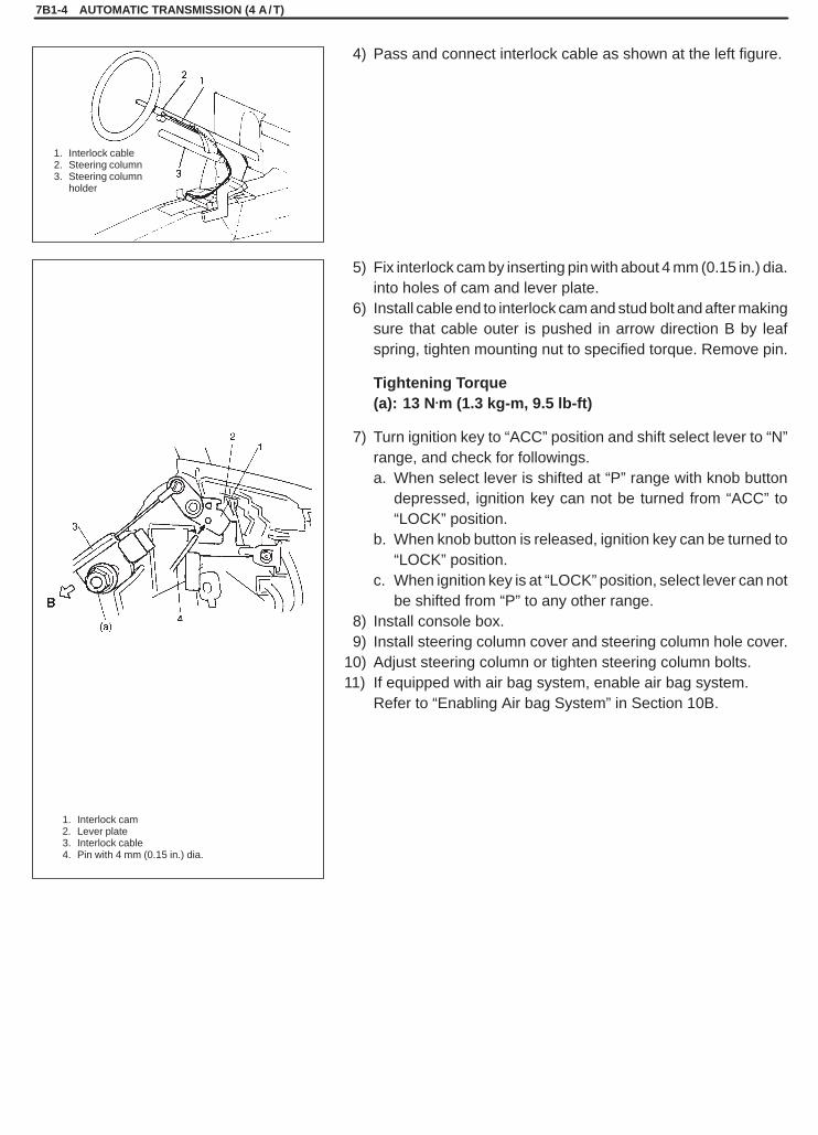
SQHokubei(Supple)
7B1-4 AUTOMATIC TRANSMISSION (4 A /T)
1. Interlock cable2. Steering column3. Steering column
holder
1. Interlock cam2. Lever plate3. Interlock cable4. Pin with 4 mm (0.15 in.) dia.
4) Pass and connect interlock cable as shown at the left figure.
5) Fix interlock cam by inserting pin with about 4 mm (0.15 in.) dia.into holes of cam and lever plate.
6) Install cable end to interlock cam and stud bolt and after makingsure that cable outer is pushed in arrow direction B by leafspring, tighten mounting nut to specified torque. Remove pin.
Tightening Torque(a): 13 N.m (1.3 kg-m, 9.5 lb-ft)
7) Turn ignition key to “ACC” position and shift select lever to “N”range, and check for followings.a. When select lever is shifted at “P” range with knob button
depressed, ignition key can not be turned from “ACC” to“LOCK” position.
b. When knob button is released, ignition key can be turned to“LOCK” position.
c. When ignition key is at “LOCK” position, select lever can notbe shifted from “P” to any other range.
8) Install console box.9) Install steering column cover and steering column hole cover.
10) Adjust steering column or tighten steering column bolts.11) If equipped with air bag system, enable air bag system.
Refer to “Enabling Air bag System” in Section 10B.
SQHokubei(Supple)
8B
LIGHTING SYSTEM 8B-1
SECTION 8B
LIGHTING SYSTEMWARNING:For vehicles equipped with Supplemental Restraint (Air Bag) System:� Service on and around the air bag system components or wiring must be performed only by an autho-
rized SUZUKI dealer. Refer to “Air Bag System Components and Wiring Location View” under “Gener-al Description” in air bag system section in order to confirm whether you are performing service onor near the air bag system components or wiring. Please observe all WARNINGS and “Service Precau-tions” under “On-Vehicle Service” in air bag system section before performing service on or aroundthe air bag system components or wiring. Failure to follow WARNINGS could result in unintentionalactivation of the system or could render the system inoperative. Either of these two conditions mayresult in severe injury.
� Technical service work must be started at least 90 seconds after the ignition switch is turned to the“LOCK” position and the negative cable is disconnected from the battery. Otherwise, the system maybe activated by reserve energy in the Sensing and Diagnostic Module (SDM).
NOTE:For the descriptions (items) not found in this section, refer to the same section of Service Manual men-tioned in FOREWORD of this manual.
CONTENTS
ON-VEHICLE SERVICE 8B- 2. . . . . . . . . . . . . . . . . . . . . . . . . . . . . . . . . . . . . . . . . . . . . . . . . . . . . . . . . . . . . . . . . . . . Hazard Relay 8B- 2. . . . . . . . . . . . . . . . . . . . . . . . . . . . . . . . . . . . . . . . . . . . . . . . . . . . . . . . . . . . . . . . . . . . . . . . . . . .

SQHokubei(Supple)
1. Hazard relay2. Junction box3. Fuse box
Type A
Type B3
3
2
8B-2 LIGHTING SYSTEM
ON-VEHICLE SERVICEHAZARD RELAYINSPECTIONConnect battery and tester as shown.Unless a continued click sound is heard, replace relay.
SQHokubei(Supple)
8C
INSTRUMENTATION/DRIVER INFORMATION 8C-1
SECTION 8C
INSTRUMENTATION/DRIVER INFORMATIONWARNING:For vehicles equipped with Supplemental Restraint (Air Bag) System:� Service on and around the air bag system components or wiring must be performed only by an autho-
rized SUZUKI dealer. Refer to “Air Bag System Components and Wiring Location View” under “Gener-al Description” in air bag system section in order to confirm whether you are performing service onor near the air bag system components or wiring. Please observe all WARNINGS and “Service Precau-tions” under “On-Vehicle Service” in air bag system section before performing service on or aroundthe air bag system components or wiring. Failure to follow WARNINGS could result in unintentionalactivation of the system or could render the system inoperative. Either of these two conditions mayresult in severe injury.
� Technical service work must be started at least 90 seconds after the ignition switch is turned to the“LOCK” position and the negative cable is disconnected from the battery. Otherwise, the system maybe activated by reserve energy in the Sensing and Diagnostic Module (SDM).
NOTE:For the descriptions (items) not found in this section, refer to the same section of Service Manual men-tioned in FOREWORD of this manual.
CONTENTS
GENERAL DESCRIPTION 8C- 2. . . . . . . . . . . . . . . . . . . . . . . . . . . . . . . . . . . . . . . . . . . . . . . . . . . . . . . . . . . . . . . . . . Combination Meter 8C- 2. . . . . . . . . . . . . . . . . . . . . . . . . . . . . . . . . . . . . . . . . . . . . . . . . . . . . . . . . . . . . . . . . . . . . . .
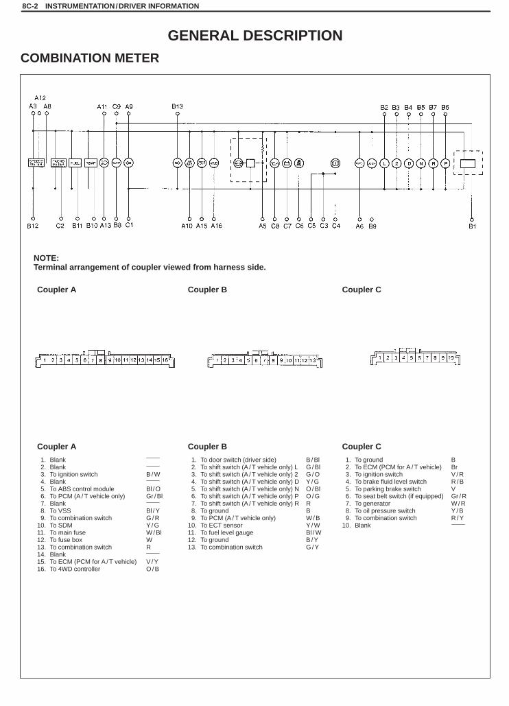
SQHokubei(Supple)
8C-2 INSTRUMENTATION/DRIVER INFORMATION
1. To door switch (driver side) B / Bl2. To shift switch (A / T vehicle only) L G / Bl3. To shift switch (A / T vehicle only) 2 G / O4. To shift switch (A / T vehicle only) D Y / G5. To shift switch (A / T vehicle only) N O / Bl6. To shift switch (A / T vehicle only) P O / G7. To shift switch (A / T vehicle only) R R8. To ground B9. To PCM (A / T vehicle only) W / B
10. To ECT sensor Y / W11. To fuel level gauge Bl / W12. To ground B / Y13. To combination switch G / Y
NOTE:Terminal arrangement of coupler viewed from harness side.
Coupler A Coupler B Coupler C
Coupler A Coupler B Coupler C
1. Blank2. Blank3. To ignition switch B / W4. Blank5. To ABS control module Bl / O6. To PCM (A / T vehicle only) Gr / Bl7. Blank8. To VSS Bl / Y9. To combination switch G / R
10. To SDM Y / G11. To main fuse W / Bl12. To fuse box W13. To combination switch R14. Blank15. To ECM (PCM for A / T vehicle) V / Y16. To 4WD controller O / B
1. To ground B2. To ECM (PCM for A / T vehicle) Br3. To ignition switch V / R4. To brake fluid level switch R / B5. To parking brake switch V6. To seat belt switch (if equipped) Gr / R7. To generator W / R8. To oil pressure switch Y / B9. To combination switch R / Y
10. Blank
GENERAL DESCRIPTION
COMBINATION METER
SQHokubei(Supple)
8D
WINDOWS, MIRRORS, SECURITY AND LOCKS 8D-1
SECTION 8D
WINDOWS, MIRRORS, SECURITY AND LOCKSWARNING:For vehicles equipped with Supplemental Restraint (Air Bag) System:� Service on and around the air bag system components or wiring must be performed only by an autho-
rized SUZUKI dealer. Refer to “Air Bag System Components and Wiring Location View” under “Gener-al Description” in air bag system section in order to confirm whether you are performing service onor near the air bag system components or wiring. Please observe all WARNINGS and “Service Precau-tions” under “On-Vehicle Service” in air bag system section before performing service on or aroundthe air bag system components or wiring. Failure to follow WARNINGS could result in unintentionalactivation of the system or could render the system inoperative. Either of these two conditions mayresult in severe injury.
� Technical service work must be started at least 90 seconds after the ignition switch is turned to the“LOCK” position and the negative cable is disconnected from the battery. Otherwise, the system maybe activated by reserve energy in the Sensing and Diagnostic Module (SDM).
NOTE:For the descriptions (items) not found in this section, refer to the same section of Service Manual men-tioned in FOREWORD of this manual.
CONTENTS
ON-VEHICLE SERVICE 8D- 2. . . . . . . . . . . . . . . . . . . . . . . . . . . . . . . . . . . . . . . . . . . . . . . . . . . . . . . . . . . . . . . . . . . . Windshield Wiper 8D- 2. . . . . . . . . . . . . . . . . . . . . . . . . . . . . . . . . . . . . . . . . . . . . . . . . . . . . . . . . . . . . . . . . . . . . . . . .

SQHokubei(Supple)
1. Battery2. Wiper motor3. � -Red lead4. � -Black lead5. Jumper
Type B
Type A
Type C
Type A
Type B
Type C
8D-2 WINDOWS, MIRRORS, SECURITY AND LOCKS
ON-VEHICLE SERVICE
WINDSHIELD WIPERINSPECTION
Wiper Motor1) As illustrated, use a 12 V battery to connect its (+) terminal to ter-
minal “A”, and its (–) terminal to Black lead wire.If motor rotates at a low revolution speed of 45 to 55 rpm, it isproper. For high speed check, connect battery (+) terminal to ter-minal “B”, and its (–) terminal to Black lead wire. If motor rotatesat a high revolution speed of 67 to 83 rpm, it is proper.
2) Testing automatic stop action.a) Connect 12 V battery (+) terminal to terminal “A” of wiper mo-
tor and (–) terminal to Black lead wire and let the motor turn.b) Disconnect terminal “A” from battery, and let the motor stop.c) Connect terminal “A” and “D” with a jumper wire, and connect
terminal “C” to battery (+) terminal. Observe the motor turnsonce again then stops at a given position.
d) Repeat a) thru c) several times and inspect if the motor stopsat the given position every time.
SQHokubei(Supple)
9
BODY SERVICE 9-1
SECTION 9
BODY SERVICEWARNING:For vehicles equipped with Supplemental Restraint (Air Bag) System:� Service on and around the air bag system components or wiring must be performed only by an autho-
rized SUZUKI dealer. Refer to “Air Bag System Components and Wiring Location View” under “Gener-al Description” in air bag system section in order to confirm whether you are performing service onor near the air bag system components or wiring. Please observe all WARNINGS and “Service Precau-tions” under “On-Vehicle Service” in air bag system section before performing service on or aroundthe air bag system components or wiring. Failure to follow WARNINGS could result in unintentionalactivation of the system or could render the system inoperative. Either of these two conditions mayresult in severe injury.
� Technical service work must be started at least 90 seconds after the ignition switch is turned to the“LOCK” position and the negative cable is disconnected from the battery. Otherwise, the system maybe activated by reserve energy in the Sensing and Diagnostic Module (SDM).
�When body servicing, if shock may be applied to air bag system component parts, remove those partsbeforehand. (Refer to Section 10B.)
NOTE:� For the descriptions (items) not found in this section, refer to the same section of Service Manual men-
tioned in FOREWORD of this manual.� Fasteners are important attaching parts in that they could affect the performance of vital components
and systems, and/or could result in major repair expense. They must be replaced with one of the samepart number of with an equivalent part if replacement becomes necessary.Do not use a replacement part of lesser quality or substitute a design. Torque values must be used asspecified during reassembly to assure proper retention of these parts.
CONTENTS
BODY STRUCTURE 9- 2. . . . . . . . . . . . . . . . . . . . . . . . . . . . . . . . . . . . . . . . . . . . . . . . . . . . . . . . . . . . . . . . . . . . . . . Front Fender 9- 2. . . . . . . . . . . . . . . . . . . . . . . . . . . . . . . . . . . . . . . . . . . . . . . . . . . . . . . . . . . . . . . . . . . . . . . . . . . . . Rear Bumper 9- 3. . . . . . . . . . . . . . . . . . . . . . . . . . . . . . . . . . . . . . . . . . . . . . . . . . . . . . . . . . . . . . . . . . . . . . . . . . . . Body Dimensions 9- 4. . . . . . . . . . . . . . . . . . . . . . . . . . . . . . . . . . . . . . . . . . . . . . . . . . . . . . . . . . . . . . . . . . . . . . . . .
SEAT 9- 7. . . . . . . . . . . . . . . . . . . . . . . . . . . . . . . . . . . . . . . . . . . . . . . . . . . . . . . . . . . . . . . . . . . . . . . . . . . . . . . . . . . . . Rear Seat 9- 7. . . . . . . . . . . . . . . . . . . . . . . . . . . . . . . . . . . . . . . . . . . . . . . . . . . . . . . . . . . . . . . . . . . . . . . . . . . . . . .
PAINT AND COATINGS 9- 8. . . . . . . . . . . . . . . . . . . . . . . . . . . . . . . . . . . . . . . . . . . . . . . . . . . . . . . . . . . . . . . . . . . . Metal Replacement Parts Finishing 9- 8. . . . . . . . . . . . . . . . . . . . . . . . . . . . . . . . . . . . . . . . . . . . . . . . . . . . . . . . .
CONVERTIBLE TOP 9-15. . . . . . . . . . . . . . . . . . . . . . . . . . . . . . . . . . . . . . . . . . . . . . . . . . . . . . . . . . . . . . . . . . . . . . . Canvas Top And Topbow Frames 9-15. . . . . . . . . . . . . . . . . . . . . . . . . . . . . . . . . . . . . . . . . . . . . . . . . . . . . . . . . . .
EXTERIOR AND INTERIOR TRIM 9-16. . . . . . . . . . . . . . . . . . . . . . . . . . . . . . . . . . . . . . . . . . . . . . . . . . . . . . . . . . . Floor Carpet 9-16. . . . . . . . . . . . . . . . . . . . . . . . . . . . . . . . . . . . . . . . . . . . . . . . . . . . . . . . . . . . . . . . . . . . . . . . . . . . . Roof Trim 9-17. . . . . . . . . . . . . . . . . . . . . . . . . . . . . . . . . . . . . . . . . . . . . . . . . . . . . . . . . . . . . . . . . . . . . . . . . . . . . . .
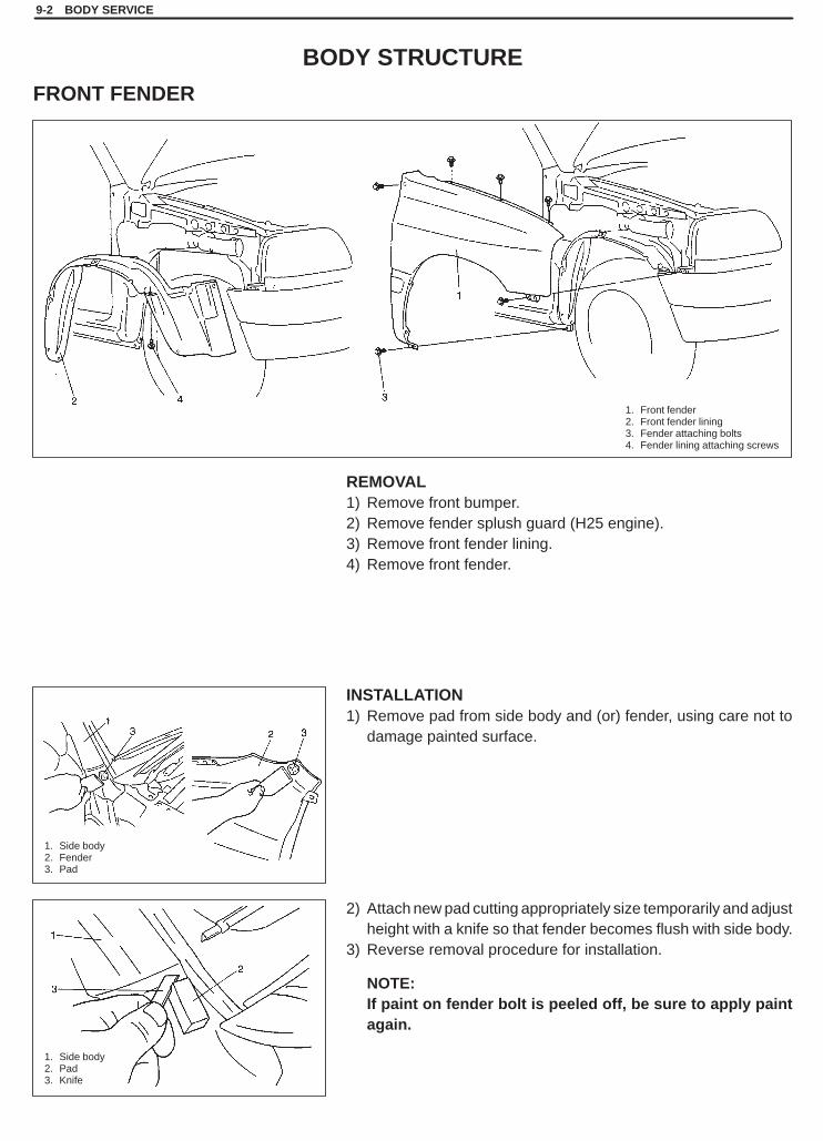
SQHokubei(Supple)
1. Side body2. Fender3. Pad
1. Side body2. Pad3. Knife
1. Front fender2. Front fender lining3. Fender attaching bolts4. Fender lining attaching screws
9-2 BODY SERVICE
BODY STRUCTURE
FRONT FENDER
REMOVAL1) Remove front bumper.2) Remove fender splush guard (H25 engine).3) Remove front fender lining.4) Remove front fender.
INSTALLATION1) Remove pad from side body and (or) fender, using care not to
damage painted surface.
2) Attach new pad cutting appropriately size temporarily and adjustheight with a knife so that fender becomes flush with side body.
3) Reverse removal procedure for installation.
NOTE:If paint on fender bolt is peeled off, be sure to apply paintagain.
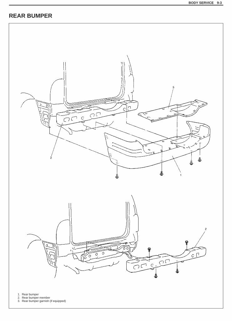
SQHokubei(Supple)
1. Rear bumper2. Rear bumper member3. Rear bumper garnish (if equipped)
BODY SERVICE 9-3
REAR BUMPER
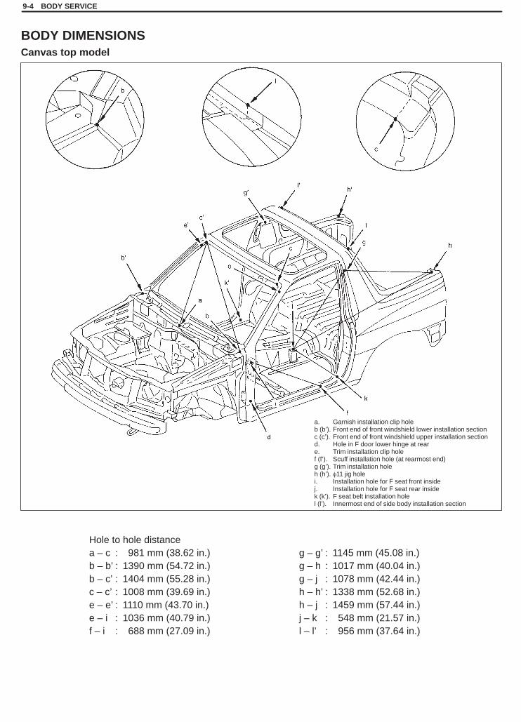
SQHokubei(Supple)
Hole to hole distancea – c : 981 mm (38.62 in.)b – b’ : 1390 mm (54.72 in.)b – c’ : 1404 mm (55.28 in.)c – c’ : 1008 mm (39.69 in.)e – e’ : 1110 mm (43.70 in.)e – i : 1036 mm (40.79 in.)f – i : 688 mm (27.09 in.)
g – g’ : 1145 mm (45.08 in.)g – h : 1017 mm (40.04 in.)g – j : 1078 mm (42.44 in.)h – h’ : 1338 mm (52.68 in.)h – j : 1459 mm (57.44 in.)j – k : 548 mm (21.57 in.)l – l’ : 956 mm (37.64 in.)
a. Garnish installation clip holeb (b’). Front end of front windshield lower installation sectionc (c’). Front end of front windshield upper installation sectiond. Hole in F door lower hinge at reare. Trim installation clip holef (f’). Scuff installation hole (at rearmost end)g (g’). Trim installation holeh (h’). �11 jig holei. Installation hole for F seat front insidej. Installation hole for F seat rear insidek (k’). F seat belt installation holel (l’). Innermost end of side body installation section
9-4 BODY SERVICE
BODY DIMENSIONSCanvas top model

SQHokubei(Supple)
Hole to hole distancea – d : 1154 mm (45.43 in.)a – f : 1150 mm (45.28 in.)b – f : 1165 mm (45.87 in.)c – e : 1142 mm (44.96 in.)c – g : 1246 mm (49.06 in.)d – e : 1146 mm (45.12 in.)
a. Hole in door upper hinge at rearb. Hole in door lower hinge at rearc. Trim installation clip holed. �7 jig holee. Scuff installation hole (rearmost end)f. Door striker lower section installation holeg. F seat belt installation hole
BODY SERVICE 9-5
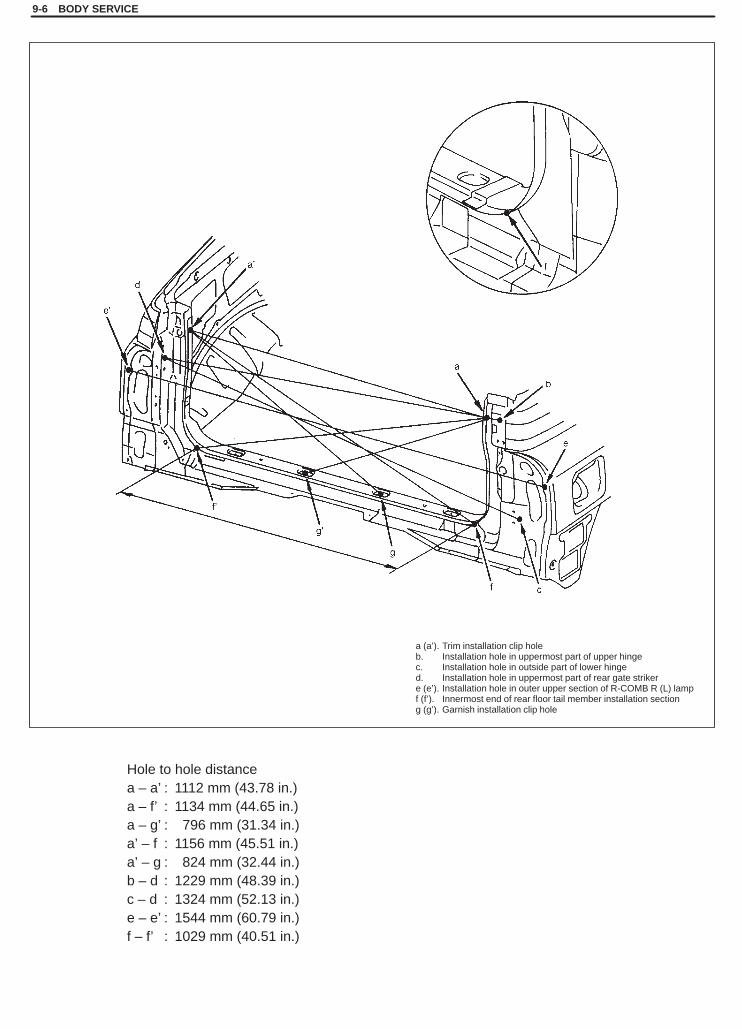
SQHokubei(Supple)
Hole to hole distancea – a’ : 1112 mm (43.78 in.)a – f’ : 1134 mm (44.65 in.)a – g’ : 796 mm (31.34 in.)a’ – f : 1156 mm (45.51 in.)a’ – g : 824 mm (32.44 in.)b – d : 1229 mm (48.39 in.)c – d : 1324 mm (52.13 in.)e – e’ : 1544 mm (60.79 in.)f – f’ : 1029 mm (40.51 in.)
a (a’). Trim installation clip holeb. Installation hole in uppermost part of upper hingec. Installation hole in outside part of lower hinged. Installation hole in uppermost part of rear gate strikere (e’). Installation hole in outer upper section of R-COMB R (L) lampf (f’). Innermost end of rear floor tail member installation sectiong (g’). Garnish installation clip hole
9-6 BODY SERVICE
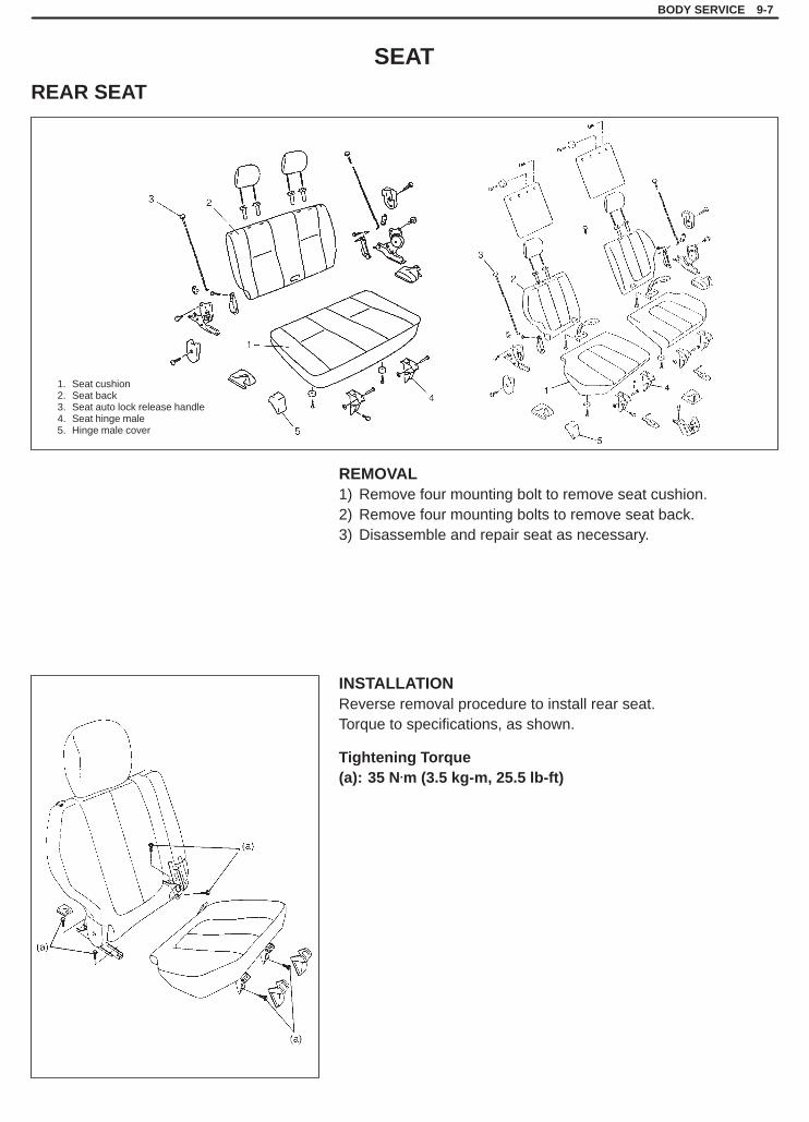
SQHokubei(Supple)
1. Seat cushion2. Seat back3. Seat auto lock release handle4. Seat hinge male5. Hinge male cover
BODY SERVICE 9-7
SEAT
REAR SEAT
REMOVAL1) Remove four mounting bolt to remove seat cushion.2) Remove four mounting bolts to remove seat back.3) Disassemble and repair seat as necessary.
INSTALLATIONReverse removal procedure to install rear seat.Torque to specifications, as shown.
Tightening Torque(a): 35 N.m (3.5 kg-m, 25.5 lb-ft)

SQHokubei(Supple)
1. Side body inner panel2. Rear wheel housing panel3. Rear floor panel4. Center floor panel
“A”: Apply sealant“B”: Brush treatment
5. Front floor panel6. Center floor member7. Side sill inner panel
9-8 BODY SERVICE
PAINT AND COATING
METAL REPLACEMENT PARTS FINISHINGSEALANT APPLICATION AREACanvas top model
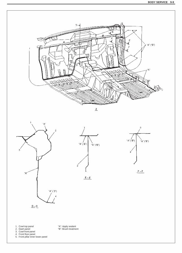
SQHokubei(Supple)
BODY SERVICE 9-9
1. Cowl top panel2. Dash panel3. Cowl front panel4. Front floor panel5. Front pillar inner lower panel
“A”: Apply sealant“B”: Brush treatment

SQHokubei(Supple)
9-10 BODY SERVICE
1. Side body inner panel2. Side body outer panel3. Front pillar inner panel4. Front pillar upper reinforcement5. Rear wheel housing panel6. Fuel inlet box7. Center pillar reinforcement8. Center pillar joint outer panel9. Center pillar joint inner panel
10. Tail upper member11. Back pillar outer panel
“A”: Apply sealant“B”: Brush treatment“C”: Wipe

SQHokubei(Supple)
BODY SERVICE 9-11
Sealant width “W”: more than 5 mm
Be free from protrudeof sealant outside fromthis line
“A”: Apply sealant
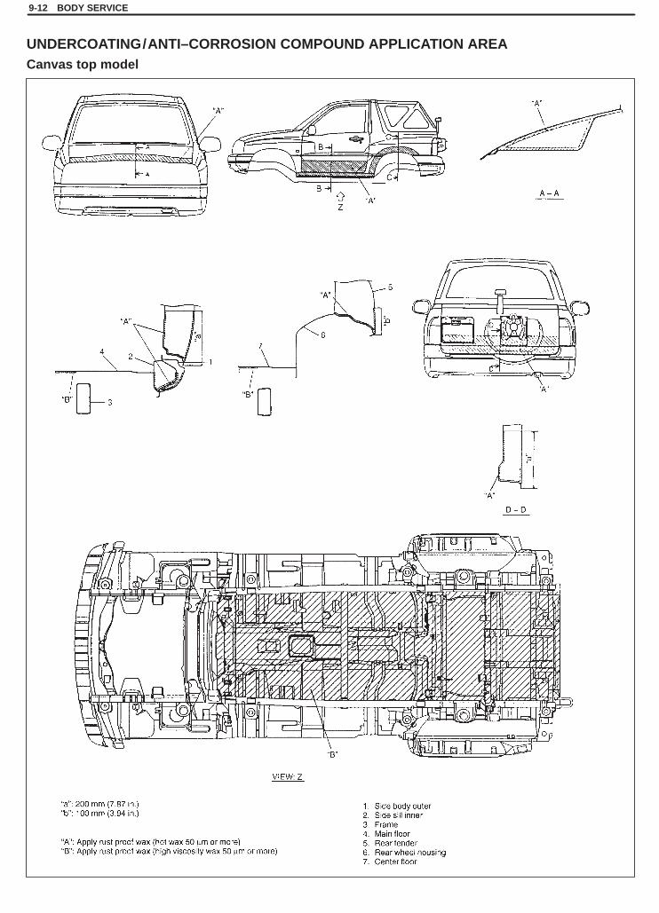
SQHokubei(Supple)
9-12 BODY SERVICE
UNDERCOATING/ANTI–CORROSION COMPOUND APPLICATION AREACanvas top model
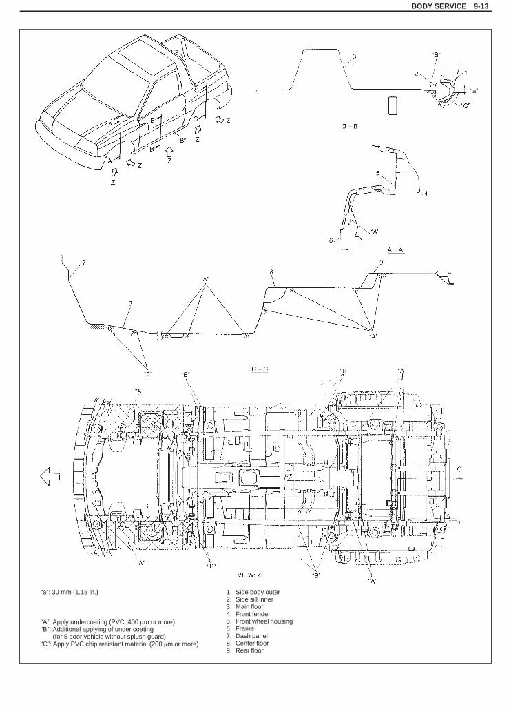
SQHokubei(Supple)
BODY SERVICE 9-13
“a”: 30 mm (1.18 in.)
“A”: Apply undercoating (PVC, 400 �m or more)“B”: Additional applying of under coating “B”: (for 5 door vehicle without splush guard)“C”: Apply PVC chip resistant material (200 �m or more)
1. Side body outer2. Side sill inner3. Main floor4. Front fender5. Front wheel housing6. Frame7. Dash panel8. Center floor9. Rear floor
“a”

SQHokubei(Supple)
9-14 BODY SERVICE
“a”: 240 mm (9.45 in.)“b”: 20 mm (0.79 in.)“c”: 40 mm (1.57 in.)“d”: 134 mm (5.28 in.)“e”: 177 mm (6.97 in.)
“A”: Black paint
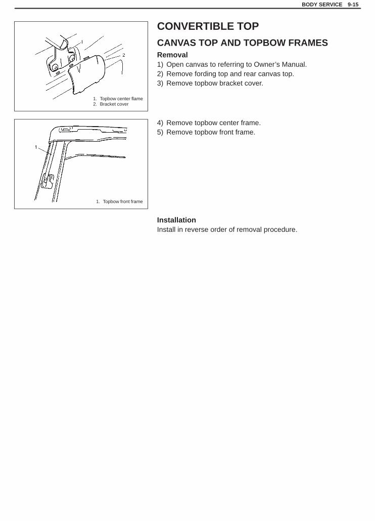
SQHokubei(Supple)
1. Topbow center flame2. Bracket cover
1. Topbow front frame
BODY SERVICE 9-15
CONVERTIBLE TOP
CANVAS TOP AND TOPBOW FRAMESRemoval1) Open canvas to referring to Owner’s Manual.2) Remove fording top and rear canvas top.3) Remove topbow bracket cover.
4) Remove topbow center frame.5) Remove topbow front frame.
InstallationInstall in reverse order of removal procedure.

SQHokubei(Supple)
9-16 BODY SERVICE
1. Front floor carpet2. Luggage floor carpet3. Dash panel insulation
1. Dash side trim2. Front side sill scuffs3. Center pillar inner
lower trim
4. Rear side sill scuff5. Fastener6 Side sill scuff7. Rear quarter lower trim
EXTERIOR AND INTERIOR TRIM
FLOOR CARPET
FRONT FLOOR CARPET
REMOVAL1) Remove front seats and rear seat cushions.2) Remove seat belt lower anchor bolt.3) Remove dash side trims, front side sill scuffs (5 door and 3 door
model), center pillar inner lower rims (5 door and 3 door model),rear side sill scuffs (5 door and 3 door model), side sill scuffs(Canvas top model) and rear quarter lower trim.
4) Remove parking brake lever cover, console box and consolebox front extension.
5) Remove front floor carpet.
INSTALLATIONReverse removal sequence to install front floor carpet, noting fol-lowing point.�When tightening seat belt anchor bolt, refer to Section 10A
“FRONT SEAT BELT WITHOUT PRITENSIONER” for tighteningtorque.

SQHokubei(Supple)
1. Canvas top2. Rear topbow3. Side body garnish4. Luggage mat end garnish5. Assistant grip6. Sunshade assembly7. Sunshade hook8. Front topbow lock9. Canvas top snap
10. Front seat belt11. Front pillar trim12. Rear side inner lower trim13. Rear side inner upper trim14. Room light connector15. Room light harness clamp16. Roof trim17. Left-front seat belt
BODY SERVICE 9-17
ROOF TRIMREMOVAL
1) Remove canvas top2) Remove rear topbow.3) Remove side body garnishes.4) Remove luggage mat end garnish.5) Remove assistant grips.6) Remove sunshade assemblies.7) Remove sunshade hooks.8) Remove front topbow locks.9) Remove canvas top snaps.
10) Remove front seat belts.11) Remove front pillar trims.12) Remove rear side inner lower trims.13) Remove rear side inner upper trims.14) Disconnect room light connector and remove room light har-
ness clamp.15) Remove roof trim.
CAUTION:Be very careful not to separate roof trim consists of 4components when removing. If disassemble it, it couldnot be assembled to original unit.

SQHokubei(Supple)
1. Roof trim2. Room light3. Room light lens
4. Clip5. Screw6. Room light harness7. Marking tape
1. Seat belt
9-18 BODY SERVICE
INSTALLATION1) Set room light and clip to roof trim.2) Set room light harness to roof trim with marking tape.
3) Reverse removal sequence to install roof trim.
Tightening Torque(a): 35 N.m (3.5 kg-m, 25.3 lb-ft)

SQHokubei(Supple)
SEAT BELT 10A-1
10A
SECTION 10A
SEAT BELTWARNING:For vehicles equipped with Supplemental Restraint (Air Bag) System:� Service on and around the air bag system components or wiring must be performed only by an autho-
rized SUZUKI dealer. Refer to “Air Bag System Components and Wiring Location View” under “Gener-al Description” in air bag system section in order to confirm whether you are performing service onor near the air bag system components or wiring. Please observe all WARNINGS and “Service Precau-tions” under “On-Vehicle Service” in air bag system section before performing service on or aroundthe air bag system components or wiring. Failure to follow WARNINGS could result in unintentionalactivation of the system or could render the system inoperative. Either of these two conditions mayresult in severe injury.
� Technical service work must be started at least 90 seconds after the ignition switch is turned to the“LOCK” position and the negative cable is disconnected from the battery. Otherwise, the system maybe activated by reserve energy in the Sensing and Diagnostic Module (SDM).
� The procedures in this section must be followed in the order listed to disable the air bag system tem-porarily and prevent false diagnostic trouble codes from setting. Failure to follow procedures couldresult in possible activation of the air bag system, personal injury or otherwise unneeded air bag sys-tem repairs.
CAUTION:When fasteners are removed, always reinstall them at the same location from which they were re-moved. If a fastener needs to be replaced, use the correct part number fastener for that application. Ifthe correct part number fastener is not available, a fastener of equal size and strength (or stronger) maybe used. Fasteners that are not reused, and those requiring thread-locking compound, will be calledout. The correct torque value must be used when installing fasteners that require it. If the above proce-dures are not followed, parts or system damage could result.
NOTE:� To check whether the vehicle is equipped with a seat belt pretensioner or not, refer to the Owner’s Manu-
al.� For the descriptions (items) not found in this section, refer to the same section of the Service Manual
mentioned in FOREWORD of this manual.
CONTENTS
ON-VEHICLE SERVICE 10A- 2. . . . . . . . . . . . . . . . . . . . . . . . . . . . . . . . . . . . . . . . . . . . . . . . . . . . . . . . . . . . . . . . . . . . Service Precautions 10A- 2. . . . . . . . . . . . . . . . . . . . . . . . . . . . . . . . . . . . . . . . . . . . . . . . . . . . . . . . . . . . . . . . . . . . . .
Handling and Storage 10A- 2. . . . . . . . . . . . . . . . . . . . . . . . . . . . . . . . . . . . . . . . . . . . . . . . . . . . . . . . . . . . . . . . . . . Front Seat Belt with Pretensioner 10A- 3. . . . . . . . . . . . . . . . . . . . . . . . . . . . . . . . . . . . . . . . . . . . . . . . . . . . . . . . . . .
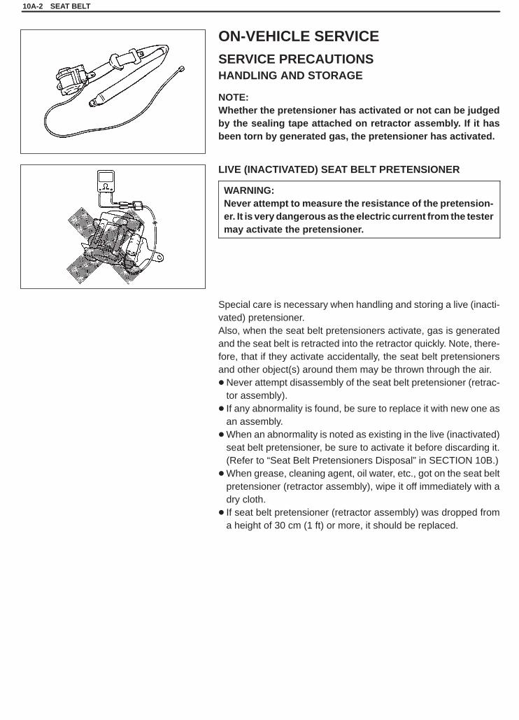
SQHokubei(Supple)
10A-2 SEAT BELT
ON-VEHICLE SERVICE
SERVICE PRECAUTIONSHANDLING AND STORAGE
NOTE:Whether the pretensioner has activated or not can be judgedby the sealing tape attached on retractor assembly. If it hasbeen torn by generated gas, the pretensioner has activated.
LIVE (INACTIVATED) SEAT BELT PRETENSIONER
WARNING:Never attempt to measure the resistance of the pretension-er. It is very dangerous as the electric current from the testermay activate the pretensioner.
Special care is necessary when handling and storing a live (inacti-vated) pretensioner.Also, when the seat belt pretensioners activate, gas is generatedand the seat belt is retracted into the retractor quickly. Note, there-fore, that if they activate accidentally, the seat belt pretensionersand other object(s) around them may be thrown through the air.�Never attempt disassembly of the seat belt pretensioner (retrac-
tor assembly).� If any abnormality is found, be sure to replace it with new one as
an assembly.�When an abnormality is noted as existing in the live (inactivated)
seat belt pretensioner, be sure to activate it before discarding it.(Refer to “Seat Belt Pretensioners Disposal” in SECTION 10B.)
�When grease, cleaning agent, oil water, etc., got on the seat beltpretensioner (retractor assembly), wipe it off immediately with adry cloth.
� If seat belt pretensioner (retractor assembly) was dropped froma height of 30 cm (1 ft) or more, it should be replaced.

SQHokubei(Supple)
SEAT BELT 10A-3
1. Exhaust hole
NGNG
WARNING:� For handling and storage of a live seat belt pretensioner,
select a place where the ambient temperature below65�C (150�F), without high humidity and away from elec-tric noise.
�Never carry the seat belt pretensioner by the wires orconnector on the underside of the pretensioner.
�When placing a live seat belt pretensioner on the work-bench or some place like that, be sure not to lay it withits exhaust hole provided side facing down. It is also pro-hibited to put something on its face with an exhaust holeor to put a seat belt pretensioner on top of another.Otherwise, personal injury may result.
FRONT SEAT BELT WITH PRETENSIONERINSPECTIONWhen checking seat belt with pretensioner, use following checkitems in addition to those specified for seat belt without pretension-er described in the same section of the Service Manual mentionedin FOREWORD of this manual.
WARNING:Never measure resistance of pretensioner or disassembleit. Otherwise, personal injury may result.
CAUTION:If seat belt pretensioner (retractor assembly) was droppedfrom a height of 30 cm (1 ft) or more, it should be replaced.
Check retractor assembly with seat belt pretensioner appearancevisually for following symptoms and if any one of them is applicable,replace it with a new one as an assembly.� Pretensioner has activated.� There is a crack in seat belt pretensioner (retractor assembly).� Wire harness or connector is damaged.� Seat belt pretensioner (retractor assembly) is damaged or a
strong impact (e.g., dropping) was applied to it.
SQHokubei(Supple)
10B
AIR BAG SYSTEM 10B-1
SECTION 10B
AIR BAG SYSTEMWARNING:� Service on or around the air bag system components or wiring must be performed only by an autho-
rized SUZUKI dealer. Please observe all WARNINGS and “Service Precautions” under “On-VehicleService” in this section before performing service on or around the air bag system components orwiring. Failure to follow WARNINGS could result in unintended activation of the system or could ren-der the system inoperative. Either of these two conditions may result in severe injury.
� The procedures in this section must be followed in the order listed to disable the air bag system tem-porarily and prevent false diagnostic trouble codes from setting. Failure to follow procedures couldresult in possible activation of the air bag system, personal injury or otherwise unneeded air bag sys-tem repairs.
CAUTION:When fasteners are removed, always reinstall them at the same location from which they were re-moved. If a fastener needs to be replaced, use the correct part number fastener for that application. Ifthe correct part number fastener is not available, a fastener of equal size and strength (or stronger) maybe used. Fasteners that are not reused, and those requiring thread-locking compound, will be calledout. The correct torque value must be used when installing fasteners that require it. If the above condi-tions are not followed, parts or system damage could result.
NOTE:For the descriptions (items) not found in this section, refer to the same section of the Service Manual men-tioned in FOREWORD of this manual.
CONTENTS
ON-VEHICLE SERVICE 10B- 2. . . . . . . . . . . . . . . . . . . . . . . . . . . . . . . . . . . . . . . . . . . . . . . . . . . . . . . . . . . . . . . . . . . . Service Precautions 10B- 2. . . . . . . . . . . . . . . . . . . . . . . . . . . . . . . . . . . . . . . . . . . . . . . . . . . . . . . . . . . . . . . . . . . . . .
Handling and Storage 10B- 2. . . . . . . . . . . . . . . . . . . . . . . . . . . . . . . . . . . . . . . . . . . . . . . . . . . . . . . . . . . . . . . . . . .

SQHokubei(Supple)
2-1. Webbing2-2. Retractor assembly2-1. Seat belt pretensioner2-2. Seat belt pretensioner harness
10B-2 AIR BAG SYSTEM
ON-VEHICLE SERVICE
SERVICE PRECAUTIONSHANDLING AND STORAGELIVE (INACTIVATED) SEAT BELT PRETENSIONERSSpecial care is necessary when handling and storing a live (inacti-vated) seat belt pretensioners.Also, when the seat belt pretensioners activate, gas is generatedand the seat belt is retracted into the retractor quickly.Note, therefore, that if they activate accidentally, the seat belt pre-tensioners and other object(s) around them may be thrown throughthe air.
WARNING:Never attempt to measure the resistance of the seat belt pre-tensioners. It is very dangerous as the electric current fromthe tester may activate pretensioner.
�Never attempt to disassemble the seat belt pretensioners (retrac-tor assembly).
� If any abnormality is found, be sure to replace it with new one asan assembly.
�When an abnormality is noted as existing in the live (inactivated)seat belt pretensioner, be sure to activate it before discarding it.
�When grease, cleaning agent oil, water, etc., got on the seat beltpretensioners (retractor assembly), wipe it off immediately with adry cloth.
� If seat belt pretensioner was dropped from a height of 30 cm (1ft) or more, it should be replaced with a new one as an assembly.

SQHokubei(Supple)
AIR BAG SYSTEM 10B-3
1. Exhaust hole
NGNG
WARNING:� For handling and storage of a live seat belt pretensioner,
select a place where the ambient temperature below 65 �C(150�F), without high humidity and away from electricnoise.
�Never carry the seat belt pretensioner by the wires or con-nector on the underside of the pretensioner.
�When placing a live seat belt pretensioner on the work-bench or some place like that, be sure not to lay it with itsexhaust hole provided side facing down. It is also prohib-ited to put something on its face with an exhaust hole orto put a seat belt pretensioner on top of another.
Otherwise, personal injury may result.