iZone Smart Home
127
iZone Smart Home Copyright © 2021 iZone Pty Ltd and Airstream Pty Ltd
Transcript of iZone Smart Home

iZone Smart Home
Copyright © 2021 iZone Pty Ltd and Airstream Pty Ltd

1
Table of Contents 1. iZone Smart Home Systems ...................................................................................................................................................................................................
1.1. Airconditioning Control Systems ................................................................................................................................................................................................... 1.1.1. Design Consideration ...........................................................................................................................................................................................................
1.1.1.1. Fixed Ducted Constant Zone ......................................................................................................................................................................................... 1.1.1.2. Standard Electronic Constant Zone ................................................................................................................................................................................ 1.1.1.3. Dedicated Electronic Constant Zone .............................................................................................................................................................................. 1.1.1.4. Bypass Electronic Constant Zone ................................................................................................................................................................................... 1.1.1.6. Installation ..................................................................................................................................................................................................................
1.1.1.6.1. iZone Naked 150 - 155 ......................................................................................................................................................................................... 1.1.1.6.1.1. 150 Zone only ...............................................................................................................................................................................................
1.1.1.6.1.1.1. Wiring layout for up to 6 zones .............................................................................................................................................................. 1.1.1.6.1.1.2. Installation instructions ..........................................................................................................................................................................
1.1.1.6.1.2. 155 Zone only ............................................................................................................................................................................................... 1.1.1.6.1.2.1. Wiring layout for up to 6 zones .............................................................................................................................................................. 1.1.1.6.1.2.2. Installation instructions ..........................................................................................................................................................................
1.1.1.6.1.3. 150 Integrated AC unit & Zone control ........................................................................................................................................................... 1.1.1.6.1.3.1. Wiring layout for up to 6 zones .............................................................................................................................................................. 1.1.1.6.1.3.2. Installation instructions ..........................................................................................................................................................................
1.1.1.6.1.4. 155 Integrated AC unit & Zone control .......................................................................................................................................................... 1.1.1.6.1.4.1. Wiring layout for up to 6 zones .............................................................................................................................................................. 1.1.1.6.1.4.2. Installation instructions ..........................................................................................................................................................................
1.1.1.6.1.5. iZone 150-155 System initialisation ................................................................................................................................................................ 1.1.1.6.2. iZone 150-155 ......................................................................................................................................................................................................
1.1.1.6.2.1. Parts required for wireless temperature controlled zones ................................................................................................................................. 1.1.1.6.2.2. Parts required for WiFi control ....................................................................................................................................................................... 1.1.1.6.2.3. iZone 150 - 435 Configuration .......................................................................................................................................................................
1.1.1.6.2.3.1. Naked Graphics ..................................................................................................................................................................................... 1.1.1.6.2.3.2. Access Config options ............................................................................................................................................................................
1.1.1.6.2.3.2.1. SYSTEM ........................................................................................................................................................................................ 1.1.1.6.2.3.2.1.1. Initialisation ...........................................................................................................................................................................
Screen Adjustments
Number of Zones
Number of Constants
Pair Wireless Device
System Device List
Auto Configuration 1.1.1.6.2.3.2.2. ZONES ..........................................................................................................................................................................................
1.1.1.6.2.3.2.2.1. Naked Zone Controller ............................................................................................................................................................ 1.1.1.6.2.3.2.3. AC UNIT ........................................................................................................................................................................................

2
1.1.1.6.2.3.2.3.1. Controlling Sensor .................................................................................................................................................................. 1.1.1.6.2.3.2.3.2. Fan Auto ................................................................................................................................................................................ 1.1.1.6.2.3.2.3.3. Advanced Constant Control ..................................................................................................................................................... 1.1.1.6.2.3.2.3.4. Unit Auto Off.......................................................................................................................................................................... 1.1.1.6.2.3.2.3.5. Use In-Duct Energy ................................................................................................................................................................ 1.1.1.6.2.3.2.3.6. Auto mode dead band ............................................................................................................................................................
1.1.1.6.2.3.2.4. OPTIONS ...................................................................................................................................................................................... 1.1.1.6.2.3.2.4.1. Tag line 1 .............................................................................................................................................................................. 1.1.1.6.2.3.2.4.2. Tag line 2 .............................................................................................................................................................................. 1.1.1.6.2.3.2.4.3. Lock Temperatures ................................................................................................................................................................. 1.1.1.6.2.3.2.4.4. Damper Timing ...................................................................................................................................................................... 1.1.1.6.2.3.2.4.5. Reverse dampers ................................................................................................................................................................... 1.1.1.6.2.3.2.4.6. Open Dampers when AC Off ................................................................................................................................................... 1.1.1.6.2.3.2.4.7. Lock airflows .......................................................................................................................................................................... 1.1.1.6.2.3.2.4.8. Lock Minimum Airflows ........................................................................................................................................................... 1.1.1.6.2.3.2.4.9. RF Channel ............................................................................................................................................................................ 1.1.1.6.2.3.2.4.10. System time ......................................................................................................................................................................... 1.1.1.6.2.3.2.4.11. Temp Sensor ........................................................................................................................................................................
1.1.1.6.3. AC unit wiring connection ..................................................................................................................................................................................... 1.1.1.6.3.1. Actron .......................................................................................................................................................................................................... 1.1.1.6.3.2. Braemar ....................................................................................................................................................................................................... 1.1.1.6.3.3. Carrier .......................................................................................................................................................................................................... 1.1.1.6.3.4. Daikin .......................................................................................................................................................................................................... 1.1.1.6.3.5. Fujitsu .......................................................................................................................................................................................................... 1.1.1.6.3.6. Gree............................................................................................................................................................................................................. 1.1.1.6.3.7. Haier ............................................................................................................................................................................................................ 1.1.1.6.3.8. Hitachi ......................................................................................................................................................................................................... 1.1.1.6.3.9. iZone ........................................................................................................................................................................................................... 1.1.1.6.3.10. Kaden ........................................................................................................................................................................................................ 1.1.1.6.3.11. LG .............................................................................................................................................................................................................. 1.1.1.6.3.12. Midea ......................................................................................................................................................................................................... 1.1.1.6.3.13. Mitsubishi Electric ........................................................................................................................................................................................ 1.1.1.6.3.14. MHI ............................................................................................................................................................................................................ 1.1.1.6.3.15. Panasonic ................................................................................................................................................................................................... 1.1.1.6.3.16. Rinnai ......................................................................................................................................................................................................... 1.1.1.6.3.17. Samsung .................................................................................................................................................................................................... 1.1.1.6.3.18. Samsung NASA ........................................................................................................................................................................................... 1.1.1.6.3.19. Temperzone ............................................................................................................................................................................................... 1.1.1.6.3.20. Toshiba ...................................................................................................................................................................................................... 1.1.1.6.3.21. York ...........................................................................................................................................................................................................
1.1.1.7. iZone 150 & 155 Series User Manual ............................................................................................................................................................................. 1.1.1.7.1. Home Screen ....................................................................................................................................................................................................... 1.1.1.7.2. AC System Summary ............................................................................................................................................................................................ 1.1.1.7.3. AC Unit Control ....................................................................................................................................................................................................

3
1.1.1.7.3.1. Examples of Different Controlling Sensors ...................................................................................................................................................... 1.1.1.7.4. Zones ................................................................................................................................................................................................................. 1.1.1.7.5. Airflow ................................................................................................................................................................................................................. 1.1.1.7.6. Favourites ............................................................................................................................................................................................................ 1.1.1.7.7. Schedules ............................................................................................................................................................................................................

4
1. iZone Smart Home Systems
iZone Pty Ltd reserves the right to change or modify the design, specifications, software, hardware, firmware or Apps at any time without prior written or oral notice. Images and functions in this manual should be considered as indicative only and may differ from the actual iZone touch screen or Apps Congratulations on the purchase of your iZone system. iZone has been developed in Australia to provide affordable, reliable, automated control of your home or office. iZone is a scalable control system that can provide basic air-side zoning all the way up to fully integrated air conditioning unit control with individual room temperature control, occupancy sensing, lighting control, security, garden reticulation and power management. You can begin your iZone journey with a basic system then add to it as funds become available without the need to replace what you have already purchased. The iZone family is shown on the diagram below. Please check with your contractor which parts are available in your area.

5

6
1.1. Airconditioning Control Systems
1.1.1. Design Consideration
All ducted air conditioning systems should have a percentage of air passing over the indoor coil at all times. This is a safety mechanism to protect the ductwork and the AC unit. If all the zone dampers in a system are closed then flexible duct could split or be blown off the spigots, or the indoor coil could ice up. It is much less likely for the coils to ice up on modern AC units as they have in-built safety controls to prevent this occurring, but it is still good practice to ensure airflow across the coil. There are several ways of achieving this when designing a ducted air conditioning system. The final choice is the designers responsibility and this manual only suggests various options that can be used. Some options to achieve to ensure constant airflow across the indoor coil are detailed below:
➢ Fixed Ducted Constant Zone
➢ Standard Electronic Constant Zone
➢ Dedicated Electronic Constant Zone
➢ Bypass Electronic Constant Zone

7
1.1.1.1. Fixed Ducted Constant Zone
This is a relatively old fashioned way of achieving constant airflow across the coil. It requires the system to be designed with one zone that has no zone damper fitted to it. This is normally the main living area in the home or a common area in an office building. The downside with this configuration is that air will always be delivered to this area regardless of whether it is occupied or not. This reduces the diversity of the system and may necessitate a larger AC unit to be installed, thereby increasing both the capital and running costs of the system. In addition to this noise to this constant zone may increase when all other zones are closed.

8
1.1.1.2. Standard Electronic Constant Zone
Typically a zone damper would be fitted to the main living area in the home or a common area in an office building. This zone can be used like any other zone but will be automatically overridden open if required by the system to maintain the minimum airflow over the indoor coil. With an iZone system you can select as many zones as you need to be electronic constants and they will activate and deactivate progressively as required. While superior to a Fixed ducted constant zone, it does have a number of short comings. Most of the time the conditions in the standard electronic zone will be satisfactory however when required to operate to relieve pressure, conditions (temperature) in this zone will drift and may become uncomfortable. Individual room temperature control cannot be fitted to a standard electronic zone. Noise from the outlet may be higher when the electronic constant is operating.

9
1.1.1.3. Dedicated Electronic Constant Zone
In this option an additional zone is installed into the system serving an unoccupied area such as a stairwell, passage or entry. This zone is left in the closed position and will only open if required by the system. With an iZone system you can select as many dedicated zones as you need. The benefit of the dedicated electronic constant zone is that all habitable areas can have individual temperature control and if the electronic constant is required to operate it will not affect the comfort of the occupants. The downside of this type of electronic constant is that conditions in the corridor or stairwell may feel mildly uncomfortable while transiting through them and the outlet in this area may generate some noise.

10
1.1.1.4. Bypass Electronic Constant Zone
In this option an additional zone is installed into the system looping from the supply air side of the A/C fan coil unit to the return air side of the A/C fan coil unit. This bypass zone is left in the closed position and will only open if required by the system. The benefit of the Bypass Electronic Constant zone is that all habitable areas can have individual temperature control and if the electronic constant is required to operate it will not affect the comfort of the occupants. No common areas are affected by the operation of the bypass constant and there is no increase in noise when the bypass is operating. In addition to this, the use of the bypass option increases the system efficiency as any conditioned air is kept within the system reducing the load on the AC unit and assisting to cycle the AC unit off earlier. (If set up to control from the units return air sensor). Our experience has shown that systems with individual zone temperature control that are designed and configured with a bypass electronic constant zone and the AC unit, where possible controlled from “Zones” gives the best results.

11
1.1.1.6. Installation
1.1.1.6.1. iZone Naked 150 - 155
1.1.1.6.1.1. 150 Zone only
iZone 150 Zone only is a basic low-cost zone only control system which is suitable for switching zones Open and Closed. A summary of the features iZone 150 Zone only offers are listed below:
• Up to 6 zones available
• Zones air quantities can be balanced from the CECP controller (no need for separate manual balancing dampers)
• Zone airflows can be adjusted by the end user from the CECP controller
• Multiple CECP controllers can be added
• Zone temperatures can be controlled from CECP if iZone sensors are fitted to the system
• Label zone names from a standard library of names built into the controller
• Electronic constants can be set-up.
There is no facility to control the zones via WiFi . The AC unit module can be added to the iZone 150 to provide integrated AC unit and zone control.

12
1.1.1.6.1.1.1. Wiring layout for up to 6 zones

13
1.1.1.6.1.1.2. Installation instructions
General installation instructions
1. The C150 can be installed on top of the indoor fan coil unit. 2. Do not run the blue network cables alongside 240 Volt wiring. 3. Always install zones in consecutive ports starting at Zone 1. The front of the C150 is marked with the zone port numbers. 4. Do not directly hard wire the CT24ACM into the AC unit’s power supply. This may void the warranty as it will require an electrician in the
event that repair of the iZone 150 system is required. 5. Connect Zone Damper Actuators (CZDA) to the zone ports using the RJ12 cables as shown. 6. Remove the tabs on the CEPC batteries to activate power to the controller 7. Only connect the power supply to the CT24ACM port after all components have been connected. 8. Initialise the system. 9. Configure the system.

14
1.1.1.6.1.2. 155 Zone only
iZone 155 is a basic low-cost zone only control system which is suitable for switching zones Open and Closed. A summary of the features of the iZone 155 zone only are listed below:
• Up to 6 zones available
• Zones air quantities can be balanced from the CECP controller (no need for separate manual balancing dampers)
• Zone airflows can be adjusted by the end user from the CECP controller
• Multiple CECP controllers can be added
• Zone temperatures can be controlled from CECP if iZone sensors are fitted to the system
• Label zone names from a standard library of names built into the controller. Customised names can be input via your smart device.
• Electronic constants can be set up.
• WiFi or 5G control of your zones and other smart iZone devices
An AC unit module can be added to the iZone 155 to provide integrated AC unit and zone control. Click on this link to go to the iZone 155 with integrated AC unit control.
Because the iZone 155 is supplied with an iZone Bridge other iZone automation products such as lighting, irrigation, garage door control, roller blinds etc can be controlled via the iZone Home App.

15
1.1.1.6.1.2.1. Wiring layout for up to 6 zones

16
1.1.1.6.1.2.2. Installation instructions
General installation instructions
1. The C150 can be installed on top of the indoor fan coil unit. 2. Do not run the blue network cables alongside 240 Volt wiring. 3. Always install zones in consecutive ports starting at Zone 1. The front of the C150 is marked with the zone port numbers. 4. Do not directly hard wire the CT24ACM into the AC unit’s power supply. This may void the warranty as it will require an electrician in the
event that repair of the iZone 150 system is required. 5. Connect Zone Damper Actuators (CZDA) to the zone ports using the RJ12 cables as shown. 6. Remove the tabs on the CEPC batteries to activate power to the controller 7. Only connect the power supply to the CT24ACM port after all components have been connected. 8. Initialise the system. 9. Configure the system. 10. Connect the bridge to the owners modem and connect the bridge power supply. Pair the bridge to the C155 using the pair button on the CEPC screen.

17
1.1.1.6.1.3. 150 Integrated AC unit & Zone control
iZone 150 is a low cost integrated AC control system which is suitable for controlling zones and complete AC unit control. A summary of the features iZone 150 offers are listed below:
• Up to 6 zones available
• Zones air quantities can be balanced from the CECP controller (no need for separate manual balancing dampers)
• Zone airflows can be adjusted by the end user from the CECP controller
• Multiple CECP controllers can be added
• Zone temperatures can be controlled from CECP if iZone sensors are fitted to the system
• Label zone names from a standard library of names built into the controller
• Electronic constants can be setup.
• Numerous brands of AC unit can be controlled. Click on the link to which AC units are compatible and how to wire them.
There is no facility to control the system via WiFi .

18
1.1.1.6.1.3.1. Wiring layout for up to 6 zones

19
1.1.1.6.1.3.2. Installation instructions
General installation instructions 1. The C150 can be installed on top of the indoor fan coil unit. 2. Do not run the blue network cables alongside 240 Volt wiring. 3. Always install zones in consecutive ports starting at Zone 1. The front of the C150 is marked with the zone port numbers. 4. Do not directly hard wire the CT24ACM into the AC unit’s power supply. This may void the warranty as it will require an electrician in the
event that repair of the iZone 150 system is required. 5. Connect Zone Damper Actuators (CZDA) to the zone ports using the RJ12 cables as shown. 6. Connect the AC unit control cable to the C150 as per the instructions for your brand of AC unit found here
7. Remove the tabs on the CEPC batteries to activate power to the controller 8. Only connect the power supply to the CT24ACM port after all components have been connected. 9. Initialise the system. 10. Configure the system.
1.1.1.6.1.4. 155 Integrated AC unit & Zone control
iZone 155 is a low cost integrated AC control system which is suitable for controlling zones and complete AC unit control as well as full smart home control via a phone or tablet. A summary of the features iZone 155 offers are listed below:
• Up to 6 zones available • Zones air quantities can be balanced from the CECP controller (no need for separate manual balancing dampers) • Zone airflows can be adjusted by the end user from the CECP controller • Multiple CECP controllers can be added • Zone temperatures can be controlled from CECP if iZone sensors are fitted to the system • Label zone names from a standard library of names built into the controller • Electronic constants can be setup. • Numerous brands of AC unit can be controlled. Click on the link to which AC units are compatible and how to wire them.
Because the iZone 155 is supplied with an iZone Bridge other iZone automation products such as lighting, irrigation, garage door control, roller blinds etc can be controlled.

20
1.1.1.6.1.4.1. Wiring layout for up to 6 zones

21
1.1.1.6.1.4.2. Installation instructions
General installation instructions
1. The C150 can be installed on top of the indoor fan coil unit. 2. Do not run the blue network cables alongside 240 Volt wiring. 3. Always install zones in consecutive ports starting at Zone 1. The front of the C150 is marked with the zone port numbers. 4. Do not directly hard wire the CT24ACM into the AC unit’s power supply. This may void the warranty as it will require an electrician in the
event that repair of the iZone 150 system is required. 5. Connect Zone Damper Actuators (CZDA) to the zone ports using the RJ12 cables as shown. 6. Connect the AC unit control cable to the C150 as per the instructions for your brand of AC unit found here
7. Remove the tabs on the CEPC batteries to activate power to the controller 8. Only connect the power supply to the CT24ACM port after all components have been connected. 9. Initialise the system. 10. Configure the system. 11. Connect the bridge to the owners modem and connect the bridge power supply. Pair the bridge to the C155 using the pair button on the CEPC screen.

22
1.1.1.6.1.5. iZone 150-155 System initialisation
System initialisation All new or modified systems must be initialised prior to system configuration. To initialise the system, remove the power from the C150 module, wait 15 seconds and restore power to the C150 module. The time to initialise the system will vary depending on the number of motors connected. The system will also initialise when power is restored after a power failure.
1.1.1.6.2.1. Parts required for wireless temperature controlled zones

23
1.1.1.6.2.2. Parts required for WiFi control

24
1.1.1.6.2.3. iZone 150 - 435 Configuration
Each iZone system will require some degree of configuration after installation or over its lifetime.
1.1.1.6.2.3.1. Naked Graphics
iZone Naked CEPC Graphic Configuration
To access the configuration menu requires a password below are instructions to access the configuration menu
Home screen>Select Config>Type in password>wamfud>Enter
SYSTEM ZONES AC UNIT OPTIONS
Number of Zones Change Zone names Controlling Sensor Lock temperatures
Number of Constants Zone Type Fan Auto Max SP Temp
iSave Sensor Type Advanced Constant Control Min SP Temp
Pair wireless device Set Zone Area Advanced Constant Area Damper timing
Tag line 1 Commissioning Air Balance Max Unit Auto Off Reverse dampers
Tag line 2 Commissioning Air Balance Min Open dampers when AC off
Set Time Sensor Calibration Lock airflow
Auto Configure Lock min airflow
Firmware version RF Channel
Temp Sensor
Zone Only
Temp / Time
25
1.1.1.6.2.3.2. Access Config options
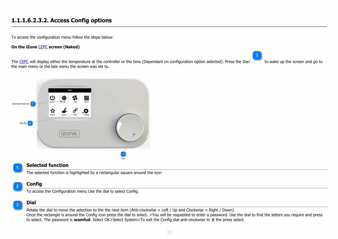
To access the configuration menu follow the steps below: On the iZone CEPC screen (Naked)
The CEPC will display either the temperature at the controller or the time (Dependant on configuration option selected). Press the Dial to wake up the screen and go to the main menu or the late menu the screen was set to.
Selected function
The selected function is highlighted by a rectangular square around the icon
Config
To access the Configuration menu Use the dial to select Config.
Dial
Rotate the dial to move the selection to the the next item (Anti-clockwise = Left / Up and Clockwise = Right / Down) Once the rectangle is around the Config icon press the dial to select. >You will be requested to enter a password. Use the dial to find the letters you require and press to select. The password is wamfud. Select OK>Select System>To exit the Config dial anti-clockwise to ≤ the press select.

26
+
Fill in the blanks
You will be requested to enter a password. Use the dial to find the letters you require and press to select.
Underscore
The underscore indicates which letter you are changing. Press the dial to select then turn the dial to find the letter you require. The default system password is wamfud
Select to enter
Once the password is complete turn the dial clockwise to take the underscore to OK > press the dial to enter the Config menu the
27
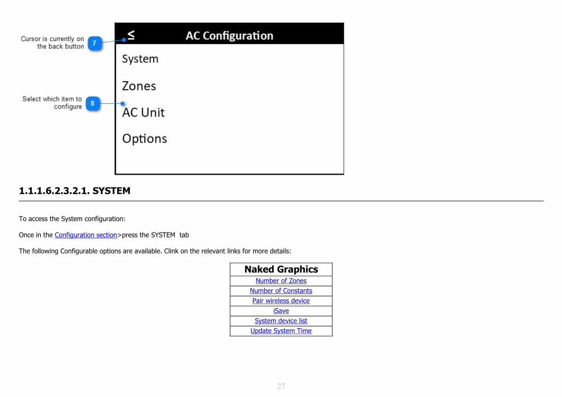
1.1.1.6.2.3.2.1. SYSTEM
To access the System configuration: Once in the Configuration section>press the SYSTEM tab The following Configurable options are available. Clink on the relevant links for more details:
Naked Graphics Number of Zones
Number of Constants
Pair wireless device
iSave
System device list
Update System Time

28
1.1.1.6.2.3.2.1.1. Initialisation
On the iZone Home App and iZone Naked CEPC It is not possible to initialise the iZone hardware from the App or the iZone Naked (CEPC) The system requires a hard re-set which can be done as follows: C150 - You will need to cycle the power on the C150 by removing and replacing the CT24AM transformer. CEPC - You will need to remove and replace one of the batteries.
Screen Adjustments
On the iZone CEPC screen (Naked).
Go to the the Config menu Go to Option > Temp / Time here you can change the following display when the screen goes to sleep:
• Display temperature or time when controller is asleep
Number of Zones On the iZone CEPC screen (Naked)
Once in the Configuration section>Select System > Scroll down to No. Zones > Select > Change the number using the dial.

29
Selected line
The line under the description identifies this function has been selected. Press the dial to change the number of zones
Select to Exit
To exit the System Config dial anti-clockwise to ≤ then press the dial to exit.
Select Number
When the number of zones is selected it will reverse out as shown. Use the dial to select the required number of zones > Select to save
Notes 1. Note the number of zones set, includes all zone barrels for supply air zones and constants

30
Number of Constants On the iZone CEPC screen (Naked)
Once in the Configuration section>Select System > Scroll down to No. Const > Select > Change the number using the dial.
Selected line
The line under the description identifies this function has been selected. Press the dial to change the number of constants
Select to exit
To exit the System Config dial anti-clockwise to ≤ then press the dial to exit.
Select Number
When the number of constants is selected it will reverse out as shown. Use the dial to select the required number of constants > Select to save.
Pair Wireless Device
On the iZone CEPC screen (Naked)
Once in the Configuration section>Select System > Scroll down to Pair device > Select >

31
Select Pair Device
This is used to pair the CEPC to the system. Sensor and the bridge can be paired using the pair button on the home screen
Select to exit
To exit the System Config dial anti-clockwise to ≤ then press the dial to exit.
System Device List
On the iZone CEPC screen (Naked)
Once in the Configuration section>Select System > Scroll down to Firmware Ver to view the current firmware version in this CEPC. It is not possible to view all the devices on the system from the CEPC controller.

32
Auto Configuration
On the iZone CEPC screen (Naked)
For information on how the Auto configuration works click on this link On the Home Screen go to configuration>Scroll down to System Configuration> Select> Scroll down to Auto Configure > Select to Auto configure the system. Warning! When you select Auto configure the current configuration will be lost.
System Configuration
On the home screen go to Config. Enter the password and select.
Auto configure
Using the dial, scroll down to Auto Configure and press select. Warning! When you select Auto configure the current configuration will be lost.

33
1.1.1.6.2.3.2.2. ZONES To access the Zones configuration: Once in the Configuration section>press the SYSTEM tab The following Configurable options are available. Clink on the relevant links for more details:
Naked Graphics Sensor Calibration
Commissioning Air Balance
Sensor Type
Set Zone Area
Change Zone names
On the iZone CEPC screen (Naked)
The following zone Configurable options are available.
• Change Zone names • Change Zone type • Change Sensor type • Set zone areas • Balance air quantities to the zone • Calibrate zone sensor
To sent the number of zones and number of constants go to System Tab

34
Zone type There are 3 different zone types to choose from:
Zone types Parts Required Description
Open / Closed Zone damper kit (CCZDK or CZDK) Zone can be Opened and Closed manually.
Constant Zone damper kit (CCZDK or CZDK) Constant, Spill, Bypass, control. To set up for advanced constant control Climate Zone damper kit (CCZDK or CZDK), Wireless
sensor, CEPC, CDTS Zone can be Opened and Closed manually. Auto climate control. Zone control button (Off / Climate) on the sensor. Set point adjustment on the CEPC or App
Sensor type There are 2 different sensor types to choose from:
Zone types Parts Required Description
No sensor Zone damper kit (CCZDK or CZDK) Zone can be Opened and Closed manually. Wireless sensor Zone damper kit (CCZDK or CZDK), Wireless
sensor, CDTS Zone can be Opened and Closed manually. Auto climate control. Zone control button (Off / Climate) on the sensor. Set point adjustment on the touch screen, or App
CEPC sensor Zone damper kit (CCZDK or CZDK), CEPC, CDTS This zone will use the temperature sensor in the CEPC. From the Options> Temp sensor you can nominate which zone is to be controlled using this sensor.
Go to AC configuration
To find out how access the configuration menu click on this link
Scroll down to Zones

35
Use the dial to scroll down to the Zones option > Press the dial to select
Scroll down to name
Use the dial to scroll down to the zones name you want to edit > Press the dial to select
Zone number
Show the zone port this zone is connected to in the C150 or C225 module
Selected line
The line under the description identifies this function has been selected. Press the dial to select this function.

36
Zone Name
When Name is selected it will reverse out as shown. Use the dial to select the required Zone name (There is a standard library of names to choose from. Custom names can only be done via the App if a bridge is connected to the system) > Select to save.
Zone Type
When Zone Type is selected it will reverse out as shown above with “6”. Use the dial to select the required Zone Type > Select to save. If the Zone Type selected is a "Constant" the screen will be populated with and addition option to hide the Constant zone from the list of zones that the user will see. To enable this select "Constant hidden"> Enable
Sensor Type
When Sensor Type is selected it will reverse out as shown above with “6”. Use the dial to select the required Sensor Type > Select to save.
Zone Area
When Zone Area is selected it will reverse out as shown above with “6”. Use the dial to select the required Zone Area > Select to save.
Air Balance (Maximum)
When Balance Max is selected it will reverse out as shown above with “6”. Use the dial to select the required Maximum % airflow > Select to save.
Air Balance (Minimum)
Scroll down to view Min. When Balance Min is selected it will reverse out as shown above with “6”. Use the dial to select the required Minimum % airflow > Select to save.
Sensor Calibration
Scroll down to view sensor calibration. When sensor calibration is selected it will reverse out as shown above with “6”. You can calibrate the sensor in +/- 0.1 degree increments.

37
1.1.1.6.2.3.2.2.1. Naked Zone Controller
On the iZone CEPC screen (Naked)
Go to Configuration > Options > Zone Only > Enable. Whilst still in the Options menu scroll to Temp Sensor> Scroll through the zone names until you find the one you want this CEPC screen to control.
Options
Once in the Configuration section use the dial to scroll down to "Options" then press dial to select
Zone only
Use the dial to scroll down to "Zone Only"
Enabled
Enable Zone only function
Temp sensor
Scroll to "Temp sensor"
Zone being controlled
Select the zone this controller is located. The sensor in this CEPC will be used to control this zone (Living in the above example)

38
Home screen
New home screen. Cannot access the rest of the system
Zone set point
This is the current zone set point. Use the dial to select and change the set point
Zone mode
Current zone mode is Climate control. Other options are Closed or Open
Zone actual temperature
The current temperature being sensed by this CEPC controller
System in-duct temperature
The current system supply air temperature
Configuration button
Select is button if you want to go back into the configuration and change from Zone only to Full system.

39
Zone Max airflow
Zone maximum air flow % is displayed here. It may be selected and changed if required. (Provided it has not been "locked" the other configuration settings
1.1.1.6.2.3.2.3. AC UNIT
To access the AC Unit configuration: Once in the Configuration section>press the AC UNIT tab. To find out how access the naked configuration menu click on this link The following Configurable options are available for the touch screen, Naked controller and App. Clink on the relevant links for more details:
Naked Graphics Controlling Sensor
Fan Auto
Advanced Constant Control
Unit Auto Off
Use in-duct energy
Auto mode dead band
1.1.1.6.2.3.2.3.1. Controlling Sensor
On the iZone CECP screen (Naked)
AC unit controlling sensors There are 4 different AC unit controlling sensor types to choose from. Please review the AC unit wiring connection for your brand of AC unit to see which of these options are available. To see how each type works click on the links below: Return Air (R/Air) Master Zones RF Sensor Once in the Configuration section>press the AC Unit Configuration>select the type of sensor your want to use>Press the dial to save and exit.

40
AC unit configuration
Go to AC unit configuration
Select
Select AC Controlling sensor
Sensor type
Select sensor to control AC unit

41
1.1.1.6.2.3.2.3.2. Fan Auto On the iZone CEPC screen (Naked) Fan Auto Control requires several configuration items to be completed. Enable Fan Auto AC unit capacity in kW Fan airflow in l/s (optional) Fan Type Zone Areas Constant or Bypass Area Once in the Configuration section>press the AC Unit Configuration>Select Fan Auto>Select Enable / Disable. Once enabled more options will be displayed. Configuration of the zone areas needs to be set up in the Zones section Select Fan airflow and using the dial and change the AC unit airflow to match the AC unit installed> Select the Fan Type installed>
Enable fan auto
Enable fan auto to display other required configuration values
Set AC unit capacity or air quantity
If an AC unit capacity is selected the iZone controller will automatically select a nominal airflow for that capacity. The exact airflow (to the nearest 50 l/s) can be input at "Fan airflow" if desired.
Set fan type
Select the number of fan speeds available on your AC unit.

42
1.1.1.6.2.3.2.3.3. Advanced Constant Control On the iZone CEPC screen (Naked)
Advanced Constant Control can be set up to provide more granular control of the constant or bypass zone. 1. Once in the Configuration section>select AC unit Configuration >Using the dial scroll down to Adv. const. ctrl. > Enable >Set the minimum area (m2) required to be serviced by the active zones, (below which the constant or bypass will be activated) 2. Configuration of the zone areas needs to be set up in the Zones section. If a hidden bypass is being used, input the area of this constant zone as 0 m2. You will see the minimum constant area set in (1) above is in parenthesise i.e. (20m2)
AC Unit configuration menu
Go to the AC unit configuration menu and scroll down to Adv. Const. ctl.
Enable Advanced Constant
Enable the Adv.const.ctrl
Set the Constant Area
Set the minimum area (m2) required to be serviced by the active zones, (below which the constant or bypass will be activated)
If a bypass is being used for the constant zone this should be hidden in the Zones section.

43
1.1.1.6.2.3.2.3.4. Unit Auto Off On the iZone CEPC screen (Naked)
Unit Auto Off can be set up to automatically turn the AC unit off if all the zones are manually closed. If temperature controlled zones close automatically to maintain the zone set point the unit will still continue to operate as normal Once in the Configuration section>press the AC unit configuration >Use the dial to scroll down to Unit auto off > Select enable/disable
Select AC unit configuration
Go to AC unit configuration menu
Scroll down to Unit auto off
Using the dial scroll down until you reach "Unit auto off"
Enable
Use the dial to enable or disable this function. Press the dial to select and save.

44
1.1.1.6.2.3.2.3.5. Use In-Duct Energy On the iZone CEPC screen (Naked) In-duct energy is explained here Once in the Configuration section>Select the AC unit configuration>Press Next to scroll down to Use induct energy>Select> Rotate the dial to change the options Disable / Enable.> Select the required option.
AC unit configuration
Go to the AC unit configuration menu
Use induct energy
Using the dial scroll down to "Use induct energ" and press the dial to select
Enable / Disable
Rotate the dial to change the options Disable / Enable. Press the dial to select the desired option.

45
1.1.1.6.2.3.2.3.6. Auto mode dead band
On the iZone CEPC screen (Naked) Auto mode dead band is explained here. Once in the Configuration section>press the AC unit configuration>Using the dial scroll down to "Auto mode dead">Press the dial to edit the required dead band> Rotate the dial to change the dead band (adjustable in 0.25oC increments)
AC unit configuration
Once in the Configuration section>press the AC unit configuration
Auto mode dead
Using the dial scroll down to "Auto mode dead" and press the dial to edit the required dead band
Select to change
Rotate the dial to change the dead band (adjustable in 0.25oC increments)

46
1.1.1.6.2.3.2.4. OPTIONS
To access the Options configuration: Once in the Configuration section>press the AC UNIT tab The following Configurable options are available. Clink on the relevant links for more details:
Naked Graphics Tag line 1
Tag line 2
Lock temperatures
Max Set Point temp limit
Min Set Point temp limit
Damper timing
Reverse dampers
Open dampers when AC off
Lock airflow
Lock min airflow
RF Channel
System device list

47
1.1.1.6.2.3.2.4.1. Tag line 1 On the iZone CEPC screen (Naked)
Tag line one is not displayed one the CEPC screen. If set it will be the first line of text seen on at the bottom of a Nano Screen or the Property address on a Nexus screen. Once in the Configuration section>press the System Configuration> Scroll down to Tagline 1 using the dial > There are a library of standard names that can be used or the CEPC will display the custom name that has been previously entered via a Nano, Nexus or the App
System Configuration
Go to the System Configuration Menu
Tag line 1
Scroll down to Tag line 1. This Tag line is not displayed on the CEPC so it is not required but will be displayed on the App or on a touch screen if used in an iZone 400 series system.
Select title
Select a title from the library of names available. Custom names can only be input via the App.

48
1.1.1.6.2.3.2.4.2. Tag line 2 On the iZone CEPC screen (Naked)
Tag line two is displayed at the top of the home screen of the CEPC. If set it will be the second line of text seen on at the bottom of a Nano Screen or the system name on a Nexus screen. Once in the Configuration section>press the System Configuration> Scroll down to Tag line 2 using the dial > There are a library of standard names that can be used or the CEPC will display the custom name that has been previously entered via a Nano, Nexus or the App
System Configuration
Go to system configuration menu
Tag line 2
Scroll down to Tag Line 2 using the dial
Tag line 2 name
Select a title from the library of names available. Custom names can only be input via the App.
Home screen
Tag line 2 is displayed on the home screen here.

49
1.1.1.6.2.3.2.4.3. Lock Temperatures
On the iZone CEPC screen (Naked)
Lock Temperatures is explained here. Once in the Configuration section>Use the dial to scroll down to Options > Press dial to select> scroll down to Lock temps> Set to Enable> Scroll down to Max SP temp> Select > Use the dial to select the maximum set point permitted> Select >Scroll down to Min SP temp> Select > Use the dial to select the minimum set point permitted> Select
Options
Once in the Configuration section use the dial to scroll down to "Options" then press dial to select
Enable Lock Temps
Scroll down to "Lock temps" and select "Enable"
Set Max set point
Scroll down to Max SP temp and set the maximum set point temperature permitted
Set Min set point
Scroll down to Min SP temp and set the minimum set point temperature permitted

50
1.1.1.6.2.3.2.4.4. Damper Timing
On the iZone CEPC screen (Naked)
For an explanation of the Damper Timing feature click on the link Once in the Configuration section>Options>Damper Timing>Press to manually set the damper time in seconds.
Options
Once in the Configuration section use the dial to scroll down to "Options" then press dial to select
Damper timing
Scroll down to Damper timing
Damper drive time
For iZone damper motors leave timing as Auto. For other motor brands with different drive times to iZone motors you will need to set the drive time in seconds.

51
1.1.1.6.2.3.2.4.5. Reverse dampers On the iZone CEPC screen (Naked)
For an explanation of the Reverse dampers feature click on the link Once in the Configuration section>Options>Damper Control>Reverse dampers>Press to reverse the operation of the dampers.
Options
Once in the Configuration section use the dial to scroll down to "Options" then press dial to select
Reverse dampers
Scroll down to "Reverse dampers"
Enable / Disable
Enable to reverse the operation of the damper motors or Disable to leave as standard

52
1.1.1.6.2.3.2.4.6. Open Dampers when AC Off On the iZone CEPC screen (Naked)
For an explanation of the Open Dampers when AC Off click on the link Once in the Configuration section>Options>Open dampers w > Enable to have all zone dampers drive to the full open position when the AC unit is turned off on the iZone system.
Options
Once in the Configuration section use the dial to scroll down to "Options" then press dial to select
Open dampers when AC Off
Scroll down to "Open dampers w"
Enable
Enable to have all zone dampers drive to the full open position when the AC unit is turned off on the iZone system.

53
1.1.1.6.2.3.2.4.7. Lock airflows On the iZone CEPC screen (Naked)
For an explanation of the Lock airflow feature click on the link Once in the Configuration section>press Options > Scroll down to "Lock airflow" > Enable or disable to lock or unlock both maximum and minimum airflow.
Options
Once in the Configuration section use the dial to scroll down to "Options" then press dial to select
Lock all airflow adjustment
To lock both maximum and minimum airflow adjustment by the user enable "Lock airflow"
Enable to lock
Use the dial to change the "Enabled". When enabled both maximum and minimum airflow adjustments are locked

54
1.1.1.6.2.3.2.4.8. Lock Minimum Airflows
On the iZone CEPC screen (Naked)
For an explanation of the Lock airflow feature click on the link Once in the Configuration section>press Options > Scroll down to "Lock min airflow"> Enable or disable to lock or unlock the minimum airflow percentages. You have options to Lock/Unlock all Airflows or just Min Airflows.
Options
Once in the Configuration section use the dial to scroll down to "Options" then press dial to select
Lock all airflow adjustment
To lock both maximum and minimum airflow adjustment by the user enable "Lock airflow"
Lock minimum airflow adjustment only
To just lock minimum airflow enable "Lock min airflow" and Disable "Lock airflow. As shown in the example above
Enable to lock
When enabled the minimum airflow is not adjustable by the end user.

55
1.1.1.6.2.3.2.4.9. RF Channel
On the iZone CEPC screen (Naked)
The iZone system transmits over 433mHz and has 8 Radio Frequency (RF) channels choose from. The factory default channel will be one of the eight channels (1-8). If the environment has other 433mHz devices transmitting they may interfere with the iZone channel. In these instances it is possible to change the iZone RF channel. Warning! If the iZone RF channel is changed it will be necessary to re-Pair all wireless devices (other than the CEPC) connected to the iZone system.
Once in the Configuration section>Options>RF channel>Select to change the channel number.
Options
Once in the Configuration section use the dial to scroll down to "Options" then press dial to select
RF Channel
Use the dial to scroll down to "Options" then press dial to select
Channel number
Use the dial to select the required channel number then press dial to select Warning! If the iZone RF channel is changed it will be necessary to re-Pair all other wireless devices connected to the iZone system. (The CEPC will not require to be re-paired)

56
1.1.1.6.2.3.2.4.10. System time
On the iZone CEPC screen (Naked)
On the Home Screen go to conflagration>Scroll down to System> Select> Scroll down to Set time > Select> Select the hours, minutes, date, month and year and change to the current > Save
System Configuration
Go to the System Configuration screen
Set Time
Using the dial, scroll down to "Set time" and select
Select to change
Select the items you would like to change. The item you are changing will be reversed out as shown
Save
Select Save to save your changes. A message will be displayed "Time Set"

57
1.1.1.6.3. AC unit wiring connection
Unit Make
Actron Hitachi Panasonic
Braemar iZone Ducted AC Units Samsung & Samsung NASA
Carrier Kaden Temperzone
Daikin LG Toshiba
Fujitsu Midea York
Gree Mitsubishi Electric Universal Control Module
Haier MHI

58
1.1.1.6.3.1. Actron
Models Connection for C325A interface
Actron ( Ultra Slim low profile series only) Indoor Model / Outdoor model LRE-071AS / URC-071AS ( 7kW )
LRE-100AS / URC-100AS ( 10kW )
LRE-130AS / URC-140AS (14kW )
12. Connect a shielded, 2 core, twisted pair control cable from the C225 / C325A to the X / Y in the fan coil unit. (This cable and connector is supplied by iZone).
13. Polarity is critical see below, for correct connection. 14. Can use RA sensor option 15. Can use Zones sensor option 16. Can use Master sensor option 17. Can use RF sensor option
Indoor fan coil unit PCB
CN40
Connect to X and Y. Polarity is critical.

59
C225 AC unit connector
Connect AC unit cable from fan coil to C225 here.
Polarity is critical
Polarity of Y an Y is critical. Make sure it is wired in accordance with these instructions on both the CN40 connector on the fan coil PCB and the C225 cable connector.
Cable from CN40
Ensure the cable is shielded, 2 core, twisted pair. This cable is pre-terminated suitable for CN40 connector and is supplied by iZone.

60
1.1.1.6.3.2. Braemar
Models Connection for C325B interface Braemar ( SDHV series inverter ducted, single phase units only)
1. Connect the AC unit propriety wired controller to the FCU PCB. 2. Enter the service mode parameters. 3. As per the instructions below set the sensor to return air for all modes 4. Set the iZone control setting 5. Set the required static pressure setting. 6. Cycle the power to the AC unit. 7. Connect a 2 core, twisted pair control cable from the C225 / C325B X / Y to CN1 in the fan coil unit. (A connector
and short cable has been provided with the C325B but will need to be extended). 8. Polarity is critical see below, for correct connection. 9. Can use RA sensor option 10. Cannot use Zones sensor option 11. Cannot use Master sensor option 12. Cannot use RF sensor option 13. Requires special cable connector from iZone 14. Requires Braemar proprietary controller for set up
Service Mode Parameters Entering Service Mode
To enter Service Mode, power must be connected to the unit and wired controller, and the unit must be switched 'OFF' at the wall control. Follow the steps below and refer to the function and parameter setting table:-

61
Service Mode Parameters Function Display Function Description Parameter Display Parameter Description
00
Temp sensor location Ensure set to '01'
01
02 03
Sensor at return air for all modes Sensor at wired control for all modes Sensor at return air for cool, dry & fan modes, at wired control for heat mode
10 íZone control Ensure set to '01'
00 01
Standard control iZone control setting
11
Indoor fan power setting Factory default '05' Adjust to suit installed static Low static = '01' High static = '09'
01
02
03
04
05
06
07
08
09
ESP (Pa) High Speed Low Speed
10 5 1
20 6 2
30 7 3
40 8 4
50 (default) 9 5
75 10 6
100 11 7
150 12 8
200 13 9

62
Indoor FCU PCB
Note connector CN1
Connector and short cable provided
I Insert the connector and short cable (see image below) into the connector CN1. Note the correct polarity for X & Y. Polarity is critical

63
C150 AC unit connector
Connect AC unit cable from fan coil to C225 here.
Polarity is critical
Polarity of Y an Y is critical. Make sure it is wired in accordance with these instructions on both the CN1 connector on the fan coil PCB and the C150 cable connector.
Cable from CN1
Connect a shielded, 2 core, twisted pair cable to the connector and short cable provided. (This cable is not provided by iZone)

64
1.1.1.6.3.3. Carrier
Models Connection for C325C interface Carrier ( SHDV series only)
1. Connect a shielded, 2 core, twisted pair control cable from the C225 / C325A to the X / Y in the fan coil unit. (This cable and connector is supplied by iZone).
2. Polarity is critical see below, for correct connection. 3. Can use RA sensor option 4. Can use Zones sensor option 5. Can use Master sensor option 6. Can use RF sensor option
Indoor fan coil unit PCB
CN40
Connect to X and Y. Polarity is critical.

65
C225 AC unit connector
Connect AC unit cable from fan coil to C225 here.
Polarity is critical
Polarity of Y an Y is critical. Make sure it is wired in accordance with these instructions on both the CN40 connector on the fan coil PCB and the C225 cable connector.
Cable from CN40
Ensure the cable is shielded, 2 core, twisted pair. This cable is pre-terminated suitable for CN40 connector and is supplied by iZone.

66
1.1.1.6.3.4. Daikin
Models Connection for C325D interface Daikin Will connect to most ducted models with a P1 / P2 terminal in the FCU
1. Take the P1 / P2 control wire from the fan coil unit and connect it to the iZone C225 / C325D
2. Connection is not polarity critical 3. Can use RA sensor option 4. Can use Zones sensor option 5. Can use Master sensor option 6. Can use RF sensor option
7. If connecting to VRF systems, the Daikin controller must be connected first to
establish the system addresses. See tips below
P1 / P2
Connect to the P1 and P2 terminals in the Daikin FCU. Polarity is not critical

67
iZone C225 module
Ensure the correct C325 module is connected for the AC unit make it is controlling
P1 / P2
Connect the P1 / P2 cable from the Daikin FCU to here. Polarity is not critical
Shielded cable
Shielded, 2 core, twisted pair cable must be used and is not supplied by iZone.

68
1.1.1.6.3.5. Fujitsu
Models Connection for C325F2 interface Fujitsu ARTC##LATU ARTG##LHTA ARTG60LDTA ARTG24LHTDP
ARTG45LHTB ARTG60LHTB ARTG54LHTC
1. Connect a shielded, 2 core, twisted pair control cable from the C225 / C325F2 to the 2 & 3 terminals in the Fujitsu FCU. Do not use the terminal 1 (12V) when connecting to an iZone system.
2. Polarity of this cable is critical see picture below. 3. Can use RA sensor option 4. Can use Zones sensor option 5. Can use Master sensor option 6. Can use RF sensor option

69
iZone C225 module
Ensure the correct C325 module is connected for the AC unit make it is controlling
2 / 3
Connect the 2 /3 cable from the Fujitsu FCU to here. Polarity is critical If polarity is connected incorrectly simply reverse the polarity and cycle the power to the AC unit and the iZone controller.
Shielded cable
Shielded, 2 core, twisted pair cable must be used and is not supplied by iZone.

70
1.1.1.6.3.6. Gree
Models Connection for C325G interface Gree ( Inverter ducted, single phase units only)
1. Connect the AC unit propriety wired controller to the FCU PCB. 2. Enter the service mode parameters. 3. As per the instructions below set the sensor to return air for all modes 4. Set the iZone control setting 5. Set the required static pressure setting. 6. Cycle the power to the AC unit. 7. Connect a 2 core, twisted pair control cable from the C225 / C325G X / Y to CN1 in the fan coil unit. (A connector
and short cable has been provided with the C325G but will need to be extended). 8. Polarity is critical see below, for correct connection. 9. Can use RA sensor option 10. Cannot use Zones sensor option 11. Cannot use Master sensor option 12. Cannot use RF sensor option 13. Requires special cable connector from iZone 14. Requires Gree proprietary controller for set up
Service Mode Parameters Entering Service Mode
To enter Service Mode, power must be connected to the unit and wired controller, and the unit must be switched 'OFF' at the wall control. Follow the steps below and refer to the function and parameter setting table:-

71
Service Mode Parameters Function Display Function Description Parameter Display Parameter Description
00
Temp sensor location Ensure set to '01'
01 02 03
Sensor at return air for all modes Sensor at wired control for all modes Sensor at return air for cool, dry & fan modes, at wired control for heat mode
10 íZone control Ensure set to '01'
00 01
Standard control iZone control setting
11
Indoor fan power setting Factory default '05' Adjust to suit installed static Low static = '01' High static = '09'
01
02
03
04
05
06
07
08
09
ESP (Pa) High Speed Low Speed
10 5 1
20 6 2
30 7 3
40 8 4
50 (default) 9 5
75 10 6
100 11 7
150 12 8
200 13 9

72
Indoor fan coil unit terminals
Indoor FCU PCB
Not connector CN1
Connector and short cable provided
Insert the connector and short cable (see image below) into the connector CN1. Note the correct polarity for X & Y. Polarity is critical

73
C225 AC unit connector
Connect AC unit cable from fan coil to C225 here.
Polarity is critical
Polarity of Y an Y is critical. Make sure it is wired in accordance with these instructions on both the CN1 connector on the fan coil PCB and the C225 cable connector.
Cable from CN1
Connect a shielded, 2 core, twisted pair cable to the connector and short cable provided. (This cable is not provided by iZone)

74
1.1.1.6.3.7. Haier
Models Connection for C325HI interface Haier ADH series only
1. Connect a shielded, 2 core, twisted pair control cable from the C225 / C325HI to the A / B terminals on the Haier Interface board YCJ-A002.
2. Connect the interconnecting cable supplied by Haier to CN24 in the fan coil unit of the Haier Interface board YCJ-A002.
3. Set the dipswitches as shown below. Polarity is critical. 4. Haier YR-E17 wired RC must be connected and set to run on return air 5. Can use RA sensor option 6. Cannot use Zones sensor option 7. Cannot use Master sensor option 8. Cannot use RF sensor option 9. Requires special cable connector. 10. Requires Haier YRE-27 Wired controller for set up and operation 11. Requires Haier Interface board YCJ-A002.

75
1.1.1.6.3.8. Hitachi
Models Connection for C325H interface
Hitachi RPI XX 1SQ series & RPI XX 2SQ
18. Connect a shielded, 2 core, twisted pair control cable from the C225 / C325H to the A / B terminals and earth in the in the fan coil unit. (This cable is supplied by the installer).
19. Polarity is not critical see below for correct connection. 20. Can use RA sensor option 21. Can use Zones sensor option 22. Can use Master sensor option 23. Can use RF sensor option

76
1.1.1.6.3.9. iZone
Models Connection for C325i interface
iZone Model numbers AD070 ( 7.0 kW )
AD105 ( 10.5 kW )
AD130 ( 13.0 kW )
AD145 ( 14.5 kW )
AD17 ( 17.0 kW )
1. Connect a 2 core + earth, twisted pair control cable from the C225 / C325i to the X / Y in the fan coil unit. This cable is supplied by iZone
2. Polarity is critical see below, for correct connection. 3. Can use RA sensor option 4. Can use Zones sensor option 5. Can use Master sensor option 6. Can use RF sensor option
7. Unit static pressure can be set in the iZone configuration
Indoor fan coil unit PCB
CN40
Connect to X and Y. Polarity is critical.

77
C225 AC unit connector
Connect AC unit cable from fan coil to C225 here.
Polarity is critical
Polarity of Y an Y is critical. Make sure it is wired in accordance with these instructions on both the CN40 connector on the fan coil PCB and the C225 cable connector.
Cable from CN40
Ensure the cable is 2 core + earth, twisted pair. This cable is pre-terminated suitable for CN40 connector and is supplied by iZone. Cable model number is CACUCM15

78
1.1.1.6.3.10. Kaden
Models Connection for C325KAD interface
Kaden (Metalflex) Model numbers KD24 ( 7.0 kW )
KD36 ( 10.5 kW )
KD42 ( 13.0 kW )
KD48 ( 14.5 kW )
KD60 ( 17.0 kW )
1. Connect a shielded, 2 core, twisted pair control cable from the C225 / C325KAD to the X / Y in the fan coil unit.This cable is supplied by iZone
2. Polarity is critical see below, for correct connection. 3. Can use RA sensor option 4. Can use Zones sensor option 5. Can use Master sensor option 6. Can use RF sensor option
Indoor fan coil unit PCB
CN40
Connect to X and Y. Polarity is critical.

79
C225 AC unit connector
Connect AC unit cable from fan coil to C225 here.
Polarity is critical
Polarity of Y an Y is critical. Make sure it is wired in accordance with these instructions on both the CN40 connector on the fan coil PCB and the C225 cable connector.
Ensure the cable is shielded, 2 core, twisted pair. This cable is pre-terminated suitable for CN40 connector and is supplied by iZone.

80
1.1.1.6.3.11. LG
Models Connection for C325LG2 interface LG Ducted units
Current range only 1. Connect the LG supplied cable from the fan coil unit to the iZone C225 module. 2. Only use the black and yellow cables. 3. Polarity is not critical. 4. Can use RA sensor option 5. Can use Zones sensor option 6. Can use Master sensor option 7. Can use RF sensor option
Connect black and yellow wires only
Use the connector supplied with the LG unit to connect from the fan coil to the iZone C225. Only connect the black and yellow cables to the C225. Polarity is not critical

81
LG control cable
Connect black and yellow cables only. Polarity is not critical
Red cable not used
Red cable is not required for iZone connection

82
1.1.1.6.3.12. Midea
Models Connection for C325MID interface Midea
DUC series only 1. Connect a shielded, 2 core, twisted pair control cable from the C225 / C325M to the X / Y in the fan coil unit.
This cable is supplied by iZone 2. Polarity is critical see below, for correct connection. 3. Can use RA sensor option 4. Can use Zones sensor option 5. Can use Master sensor option 6. Can use RF sensor option
Indoor fan coil unit PCB
CN40
Connect to X and Y. Polarity is critical.

83
C225 AC unit connector
Connect AC unit cable from fan coil to C225 here.
Polarity is critical
Polarity of Y an Y is critical. Make sure it is wired in accordance with these instructions on both the CN40 connector on the fan coil PCB and the C225 cable connector.
Ensure the cable is shielded, 2 core, twisted pair. This cable is pre-terminated suitable for CN40 connector and is supplied by iZone.

84
1.1.1.6.3.13. Mitsubishi Electric
Models Connection for C325M interface Mitsubishi Electric Current range only.
1. Take the Remote Controller (A / B) control wire from the fan coil unit and connect it to the AC Unit Control Cable on the C225 / C325M
2. Connection is not polarity critical 3. Can use RA sensor option 4. Can use Zones sensor option 5. Can use Master sensor option 6. Can use RF sensor option
Connect to A / B terminals
Connect wires to to A and B terminals. Polarity is not critical
Mitsubishi Electric FCU PCB
C225
iZone C225 module with C325M AC unit module connected
Shielded, 2 Core, twisted pair
This cable is not provided by iZone.

85
1.1.1.6.3.14. MHI
Models Connection for C325MHI interface MHI Mitsubishi Heavy Industries FDUA Series FDUM Series
1. Take the Remote Controller wires from the fan coil unit and connect it to the AC Unit Control Cable on the C225 / C325MHI
2. Connection is not polarity critical 3. Can use RA sensor option 4. Can use Zones sensor option 5. Can use Master sensor option 6. Can use RF sensor option
Connect to A / B terminals
Connect wires to to A and B terminals. Polarity is not critical
MHI FCU PCB
C225
iZone C225 module with C325MHI AC unit module connected
This cable is not provided by iZone.

86
1.1.1.6.3.15. Panasonic
Models Connection for C325P interface Panasonic S - series units only
1. Take the R1 / R2 control wire from the fan coil unit and connect it to the AC Unit Control Cable on the C225 / C325P
2. Connection is not polarity critical 3. Can use RA sensor option 4. Can use Zones sensor option 5. Can use Master sensor option 6. Can use RF sensor option
Panasonic FCU control box
Control cable to iZone
Connect the control cable to the R1 / R2 terminals

87
C225 Module
Ensure a C325P module is connected to the C225 module
Connect R1 / R2 wires here
Polarity is not critical. Use a shielded, 2 core, twisted pair cable from the FCU to the C225 module

88
1.1.1.6.3.16. Rinnai
Model Connection for C325R interface Rinnai Ducted Units DINLR XX Series only
24. Connect a shielded, 2 core, twisted pair control cable from the C225 / C325R to the X / Y in the fan coil unit. This cable is supplied by iZone
25. Polarity is critical see below, for correct connection. 26. Can use RA sensor option 27. Can use Zones sensor option 28. Can use Master sensor option 29. Can use RF sensor option
Indoor fan coil unit PCB
CN40
Connect to X and Y. Polarity is critical.

89
C225 AC unit connector
Connect AC unit cable from fan coil to C225 here.
Polarity is critical
Polarity of Y an Y is critical. Make sure it is wired in accordance with these instructions on both the CN40 connector on the fan coil PCB and the C225 cable connector.
Ensure the cable is shielded, 2 core, twisted pair. This cable is pre-terminated suitable for CN40 connector and is supplied by iZone.

90
1.1.1.6.3.17. Samsung
Indoor FCU Compatibility Model Connection for C325S interface Samsung
• R410A o AC###HBHFKH/SA - 5kW to 14Kw
1. Connect a shielded, 2 core, twisted pair control cable from the C225 / C325S to the F3 / F4 in the fan coil unit. (This cable is supplied by the installer).
2. Polarity is critical see below for correct connection. 3. Can use RA sensor option 4. Can use Zones sensor option 5. Can use Master sensor option 6. Can use RF sensor option
FCU control box
F4

91
C225 module
Ensure a C325S interface module is connect to the C225 module
F3
Polarity is critical
F4
Polarity is critical
This cable is not supplied by iZone

92
1.1.1.6.3.18. Samsung NASA
Indoor FCU Compatibility Model Connection for C325SN interface Samsung (NASA protocol)
• R410A o AC###JNHFKH/SA - 16kW to 20Kw
• R32 o AC###TNHDKG/SA - 5.2kW to 14Kw o AC160TNHFKG/SA - 16kW
1. Connect a shielded, 2 core, twisted pair control cable from the C225 / C325SN to the F3 / F4 in the fan coil unit. (This cable is supplied by the installer).
2. Polarity is critical see below for correct connection. 3. Can use RA sensor option 4. Can use Zones sensor option 5. Can use Master sensor option 6. Can use RF sensor option
FCU control box
F4
F3

93
C225 module
Ensure a C325SN interface module is connect to the C225 module
F3
Polarity is critical
F4
Polarity is critical
This cable is not supplied by iZone

94
1.1.1.6.3.19. Temperzone
Model Connection for C325TZ interface Temperzone
Condensing unit must be fitted with a UC7 (or higher) PCB
1. Connect a shielded, 2 core, twisted pair control cable from the C225 to the UC7,8 or 9 board in the condensing unit. (This cable is supplied by the installer).
2. Polarity is critical see below for correct connection. 3. Ensure the dip switches in the condensing unit are set correctly for the installed compressor type
(digital / fixed speed) and fan speed control. Refer to the Temperzone service manual. 4. Can use RA sensor option 5. Can use Zones sensor option 6. Can use Master sensor option 7. Can use RF sensor option
Temperzone UC8 or higher PCB
iZone is only compatible with Temperzone units fitted with UC8 or higher PCB's
Shielded, 2 core, twisted pair
This cable is not supplied by iZone
A
Connect A wire on this side. Polarity is critical
C225 Module
iZone C225 module must have a C325TZ module connected.
B
Connect B wire on this side. Polarity is critical

95
1.1.1.6.3.20. Toshiba
Models Connection for C325MHI interface Toshiba S-Net protocol RAV-SMXXX 3DT-A series only
1. Take the A / B control wire from the fan coil unit and connect it to the AC Unit Control Cable on the C225 / C325T
2. Connection is not polarity critical 3. Can use RA sensor option 4. Can use Zones sensor option 5. Can use Master sensor option 6. Can use RF sensor option
Connect to A / B terminals
Connect wires to to A and B terminals. Polarity is not critical
Toshiba FCU PCB
C225
iZone C225 module with C325T AC unit module connected
Shielded, 2 Core, twisted pair
This cable is not provided by iZone.

96
1.1.1.6.3.21. York
Models Connection for C325Y interface York
Current series only 1. Connect a shielded, 2 core, twisted pair control cable from the C225 / C325Y to the X / Y in the fan coil
unit.This cable is supplied by iZone 2. Polarity is critical see below, for correct connection. 3. Can use RA sensor option 4. Can use Zones sensor option 5. Can use Master sensor option 6. Can use RF sensor option
Indoor fan coil unit PCB
CN40
Connect to X and Y. Polarity is critical.

97
C225 AC unit connector
Connect AC unit cable from fan coil to C225 here.
Polarity is critical
Polarity of Y an Y is critical. Make sure it is wired in accordance with these instructions on both the CN40 connector on the fan coil PCB and the C225 cable connector.
Cable from CN40
Ensure the cable is shielded, 2 core, twisted pair. This cable is pre-terminated suitable for CN40 connector and is supplied by iZone.

98
1.1.1.7. iZone 150 & 155 Series User Manual Select the function you would like to access and click on the links:
Section Function
Home Screen YES
Address NO
System Name Generic
Weather Forecast NO
Relative Humidity NO
Outdoor Air Quality NO
Indoor Air Quality NO
Messages NO
Beep On / Off NO
Screen Settings YES
- Turn beep On / Off NO
- Change graphic style NO
- Change screen orientation NO
- Hide other services N/A
- Child lock enable NO
- Calibrate Air Quality Sensors N/A
- Adjust screen brightness, Contrast,Saturation NO
Scenes NO
Configuration NO>AC Unit Summary
Set Time YES
WiFi Connected NO
AC Unit Summary YES
AC ON/OFF YES
Mode (Cool, Heat, Vent, Dry, Auto) NO > AC Unit icon
Fan (High, Med, Low, Auto) YES
Zones YES
Favourites & Schedules YES
Sleep Timer YES

99
iSave YES - needs hardware
Quick Sensor Pair Button YES
Config YES
AC Unit Control YES
Set point adjustment YES - RA & Master control only
Mode (Cool, Heat, Vent, Dry, Auto) YES
Fan (High, Med, Low, Auto) YES
AC Unit Status NO
Actual temp YES
Zones Summary
Change Zone Status (Open, Close, Climate) YES
Change Zone Set point YES
Zone Actual Temp NO
System Induct Temp YES
Zone Airflow % YES
Zone Sensor RF status NO
Zone Sensor battery status NO
Airflow YES> Zone Airflow
Favourites & Schedules
Create a Favourite YES
Edit a Favourite YES
Run a Favourite YES
Schedule a Favourite YES
Activate / Deactivate a Schedule YES
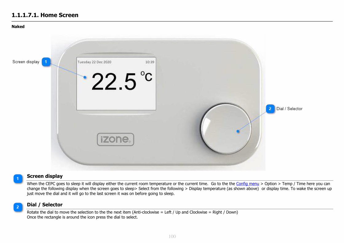
100
1.1.1.7.1. Home Screen Naked
Screen display
When the CEPC goes to sleep it will display either the current room temperature or the current time. Go to the the Config menu > Option > Temp / Time here you can change the following display when the screen goes to sleep> Select from the following > Display temperature (as shown above) or display time. To wake the screen up just move the dial and it will go to the last screen it was on before going to sleep.
Dial / Selector
Rotate the dial to move the selection to the the next item (Anti-clockwise = Left / Up and Clockwise = Right / Down) Once the rectangle is around the icon press the dial to select.

101
1.1.1.7.2. AC System Summary
ON/OFF icon
The AC unit can be turned on or off by using the dial to select the function then press the dial to change. When on the text below the icon will read AC on. When off the text below the icon will read AC Off. Please note that all AC units incorporate built in timers and delays so it may take several minutes after turning a unit on or off before you notice any change.
Mode
This icon is displaying the current mode. Select this item to access the AC Unit Control screen. In the AC Unit Control screen you can change modes, fan speeds, set points etc.

102
Fan Speed
This icon is displaying the current fan speed. Select this item to access the AC Unit Control screen. In the AC Unit Control screen you can change modes, fan speeds, set points etc.
Zone Summary
Select Zones to access the Zones Summary. For an explanation of the different Zone configurations follow this link. When the Zones button is pressed The Zone summary will open.
Favourites & Schedules
Press the Favourites button to access the Favourites Summary. When the Zones button is pressed The Favourites summary will open.
Sleep timer
Select the Sleep timeritem to toggle different times from half an hour to 12 hours. When set the AC system will run for the selected period of time and then turn off automatically. If you require a more sophisticated schedule go to Schedules
Pair sensors
This icon is used to pair wireless sensors to the iZone AC system. Do not use this icon to pair the CEPC to the C150 or C225. This needs to be paired inside the configuration menu.

103
Configuration menu
Select the Config icon to access the system configuration menu. For more information on accessing the configuration menu click on this link.
iSave
If fitted the iSave system can be manually turned on and off by selecting the iSave button. When the iSave system is turned on the AC unit will be changed automatically to Vent mode, the outside air dampers will open fully and the return air dampers will close fully. The zones will control as per normal. When the iSave system is turned off the AC unit will be changed automatically back to it's previous mode, the outside air dampers will close fully and the return air dampers will open fully. For more information about the iSave system follow this link
Dial / Selector
Rotate the dial to move the selection to the the next item (Anti-clockwise = Left / Up and Clockwise = Right / Down) Once the rectangle is around the icon press the dial to select.

104
1.1.1.7.3. AC Unit Control
Naked
To Open AC Unit Control Summary
To open the AC Unit Control window press either the Mode or Fan speed button.

105
AC Unit Control Screen
This is the AC Unit Control Screen which is accessed via the AC System Summary.
Current Controlling Set point
The current controlling set point is shown here. This view will differ depending on the configuration of the AC Unit Controlling sensor. In this graphic the AC unit is being controlled from "Zones" and the zone that is currently furtherest from set point is "Lounge" which is currently the zone that is furtherest from set point. To see other controlling sensor examples click here.
Controlling zone
The name of the zone currently controlling the AC unit
Actual temp
Actual temperature in the controlling zone

106
In duct temp
Current in-duct temperature
Current mode
Current AC Mode. Select the icon to change.
Current Fan speed
The current fan speed is displayed here. Select the fan icon to change.

107
1.1.1.7.3.1. Examples of Different Controlling Sensors
The following examples are displayed here: Return Air Sensor (RA) Master Sensor Zones RF Sensor Return Air Sensor Display
Return Air Set Point Temperature
This is the set point selected by the user. Using the dial move the cursor to underline the Set Point temperature. Press the dial to reverse the text to white in a black box. Rotate the dial clockwise to increase the SP temperature and anticlockwise to reduce the set point. Press the dial to save the required Set Point temperature. When controlling from the RA sensor it is only possible to set the set point in 1 degree increments as this is governed by the AC unit manufacturer.
Actual RA temperature
On the screen the actual return air temperature is displayed here. (not available on some AC unit makes)
108
Supply air temp
This is the air temperature inside the AC supply air ductwork
Current fan speed
This is the current fan speed and can be changed here if required
Current mode
This is the current AC unit mode and can be changed here if required

109
Master Sensor Display
Master Zone Set Point
The current zone set point is shown here. In this graphic the Master Zone is the OFFICE. The set point temperature cannot be changed here. You need to go to the Zone summary and change the set point temperature of the Master Zone there.
Current Master Zone
The current Master zone is the Lounge. If the Master zone is changed this description will change as well. To see how to change the Master zone follow this link.
Actual Temp in Master Zone
On the touch screen the actual air temperature in the Master Zone is displayed here.
Supply air temp
This is the air temperature inside the AC supply air ductwork
Current mode
This is the current AC unit mode and can be changed here if required
Current fan speed
This is the current fan speed and can be changed here if required

110
Changing The Master Zone
In the AC unit screen > Go to the Master Zone name > Select the required zone to be the master zone.
Select the Master Zone name
Using the dial move the cursor down to underline the Master Zone name > Press the dial to select the name > Rotate the dial to scroll through all the zone names > Select the new Master zone by pressing the dial when the zone name you want to use as the master zone is displayed.
Actual temp in the Master Zone
This is the new actual temperature in the master zone (Bedroom)
System supply air temp
This is the air temperature inside the AC supply air ductwork

111
Zones Controlling Sensor Display
Set point in the controlling zone
The current controlling set point is shown here. In this graphic the AC unit is being controlled from the "Lounge" which is currently the zone that is furtherest from set point.
Current controlling zone
The name of the zone currently controlling the AC unit
Actual temp in the controlling zone
The actual temperature in the controlling zone is displayed here. (May not be displayed on the App)
Supply air temp
Current temperature of the air in the supply air ductwork
Current Mode
Current AC Mode. Select to change.
Current Fan Speed
The current fan speed is displayed here. Select to change.

112
RF Sensor Display
AC Unit Set Point Temperature
This is the set point selected by the user. Using the dial move the cursor to underline the Set Point temperature. Press the dial to reverse the text to white in a black box. Rotate the dial clockwise to increase the SP temperature and anticlockwise to reduce the set point. Press the dial to save the required Set Point temperature.
Actual Temp at RF Sensor
The actual temperature of the air measured by the CEPC Sensor is displayed here.
Supply air temp
This is the air temperature inside the AC supply air ductwork
Fan Speed
This is the current fan speed and can be changed here if required
Mode
This is the current AC unit mode and can be changed here if required

113
1.1.1.7.4. Zones
Zone Summary
Using the dial, move the cursor to Zones. Press the dial to select.
Zone Details
Back button
To go back to the home page move the cursor up to the the back button and press the dial to select
Zone name
Rotate the dial to move the cursor to the Zone you want to adjust. Press the dial to enter the zone details. To change the zone name click here
Climate control
Rotate the dial until the cursor underlines the thermometer> Press select> Rotate the dial to change between different options (Climate / OPEN / CLOSE) > Press to select the required function. (Zone must be fitted with a configured iZone temperature sensor to allow this option)

114
Set point temperature
Rotate the dial until the cursor underlines the set point temperature> Press select> Rotate the dial to change the set point temperatures (Clockwise to increase the SP temperature, anticlockwise to decrease the SP temperature) > Press the dial to save the required SP temperature
Max Airflow
Rotate the dial until the cursor underlines the Max airflow percentage> Press select> Rotate the dial to change the Max Airflow % (Clockwise to increase the Max %, anticlockwise to decrease the Max %) > Press the dial to save the required Max airflow for the selected zone
Zone is Closed
Rotate the dial until the cursor underlines the Damper icon or the word Close > Press select> Rotate the dial to change between different options (Climate / OPEN / CLOSE) > Press to select the required function. (Zone must be fitted with a configured iZone temperature sensor to allow Climate control option)
Zone is open
Rotate the dial until the cursor underlines the Damper icon or the word Close > Press select> Rotate the dial to change between different options (Climate / OPEN / CLOSE) > Press to select the required function. (Zone must be fitted with a configured iZone temperature sensor to allow Climate control option)

115
1.1.1.7.5. Airflow
Airflow Summary
Zone Summary
Using the dial, move the cursor to Zones. Press the dial to select.
Airflow Details

116
Back button
To go back to the home page move the cursor up to the the back button and press the dial to select
Max Airflow
Rotate the dial until the cursor underlines the Max airflow percentage> Press select> Rotate the dial to change the Max Airflow % (Clockwise to increase the Max %, anticlockwise to decrease the Max %) > Press the dial to save the required Max airflow for the selected zone

117
1.1.1.7.6. Favourites
Favourite Summary A favourite is a short cut which allows the user to press a single button to simultaneously make multiple changes to the zones status, set points, mode, fan speed. Once a favourite has been created it can then be scheduled to start and stop at specific times during a 7 day week.
Home screen
Go to the home screen. For instructions on how to go to the home screen click on this link
Favourites and Schedules
Using the dial move the box to the Favour icon

118
Back button
To go back to the home page move the cursor up to the the back button and press the dial to select
Favourite / Schedule name
Rotate the dial to move the cursor to the Zone you want to adjust. Press the dial to enter the details for this favourite. By default the favourite names will be "Favourite 1, Favourite 2....etc. To customise the zone name you will need to do this via the App and will require a COCB WiFi bridge.
Favourite button
Rotate the dial to move the cursor to the favourite you want to run . Press the dial to run this favourite.

119
Edit pencil
Using the dial, move the cursor tot he edit pencil to edit a favourite / schedule. For more details on editing favourites and schedule see "Favourite / Schedule Details / Edit"
Schedule Active
An alarm clock as shown indicates this favourite has an active schedule.To change the schedule or to de-active the schedule see "Schedule Details / Edit"
Schedule de-activated
An alarm clock with a cross through it as shown indicates this favourite has a schedule which has been de-activated. To change the schedule or to active the schedule see "Schedule Details / Edit"

120
Favourite Details / Edit
Back button
Select the Back button to go back to the Favourite Summary . When you go back any changes you have made will be saved.
Mode for this Favourite
When this favourite is activated the AC unit mode will be changed to the mode stated here. Select to change mode (Cool, Vent, Heat, Auto, N/A). If N/A is selected the iZone system will not change the mode, from its current setting, when this favourite is activated.
Zone names
The zone names appear here. Make sure you set up each zone when setting up a favourite.
Favourite being changed
Write description here...
Fan speed for this favourite
When this favourite is activated the AC unit fan speed will be changed to speed stated here. Select to change fan speed (High, Med, Low, Auto, N/A). If N/A is selected the iZone will not change the fan speed, from its current setting, when this favourite is activated.

121
Zone is to be closed
This zone will close when this favourite is activated
SP temp for zone
This is the set point temperature this zone will be controlled at when this zone is activated. Select to change from Climate, Open, Close. To change the set point temperature on a Climate Controlled zone you will need to go to "Zones" and change the corresponding zone set point temperatures. Then return to favourites and set up the and save the favourite.
Zone status during favourite
This is the status of this zone when the zone is activated. Select to change (Climate, Open, Close).

122
1.1.1.7.7. Schedules
Schedule Summary
To configure a schedule it is necessary to first create a Favourite with the Mode, Fan Speed and zone settings that you want to run when the schedule is active. Once the favourite has been created and tested it can then be scheduled to start and / or stop at the required time. Please note if schedules overlap the following will occur in the example below: Schedule A will start at 0:800 and will stop before its scheduled time at 08:45 as it has been overridden by Schedule B Schedule B will start at 0:845 and will stop before its scheduled time at 09:15 as it has been overridden by Schedule C Schedule C start and stop at its required schedule times of 09:15 - 10:40
A favourite is a short cut which allows the user to press a single button to simultaneously make multiple changes to the zones status, set points, mode, fan speed. Once a favourite has been created it can then be scheduled to start and stop at specific times during a 7 day week.

123
Home screen
Go to the home screen. For instructions on how to go to the home screen click on this link
Favourites and Schedules
Using the dial move the box to the Favour icon

124
Back button
To go back to the home page move the cursor up to the the back button and press the dial to select
Favourite / Schedule name
Rotate the dial to move the cursor to the Zone you want to adjust. Press the dial to enter the details for this favourite. By default the favourite names will be "Favourite 1, Favourite 2....etc. To customise the zone name you will need to do this via the App and will require a COCB WiFi bridge.
Schedule Active
An alarm clock as shown indicates this favourite has an active schedule.To edit this schedule or to de-active the schedule select this icon. See "Schedule Details / Edit"
Schedule de-activated
An alarm clock with a cross through it as shown indicates this favourite has a schedule which has been de-activated. To edit this schedule or to active the schedule select this icon. See "Schedule Details / Edit"

125
Schedule Details / Edit
Back button
Press the Back button to go back to the Favourite Summary
Active days
Days this schedule will run are shown as below. (Black background and white text). Using the dial select a day and then press the dial to change the selected days
Schedule start time
This schedule will start at 18:05. on the days selected. To change the time use the dial to move the cursor to the required value > Press the dial to select > Rotate the dial to change the time> Press the dial to save the change.
Schedule Stop time
This schedule will stop at 22:30 on the days selected. To change the time use the dial to move the cursor to the required value > Press the dial to select > Rotate the dial to change the time> Press the dial to save the change.
Name of Favourite being scheduled

126
This is the favourite you are currently scheduling. To go to another favourite > Select the back button and select from the Favourite Summary
Inactive days
Days this schedule will not run are shown as below. (White background and black text). Using the dial select a day and then press the dial to change the selected days
Schedule is Activated to run
When a schedule is activated to run it will display as an alarm clock. See here for details. To change > Select the icon and rotate the dial to change from Active to De-activated. When a schedule is de-activated to not run. For example when you go away on holiday. It will display as an alarm clock with a cross through it. See here for more details .To change > Select the icon and rotate the dial to change from Active to De-activated.