IVYEAR-Smart car parking-DOC.pdf
63
` SMART CAR PARKING A Project Report Submitted in Partial Fulfillment For the Award of the Degree of BACHELOR OF TECHNOLOGY IN MECHANICAL ENGINEERING Submitted By P.SAI KUMAR (07241A0355) K.ARAVIND (07241A0378) K.MANOJ REDDY (07241A0394) K.RAKESH BABU (07241A03A4) UNDER THE GUIDANCE OF Mr.P.P.C.PRASAD Department of Mechanical Engineering GOKARAJU RANGARAJU INSTITUTE OF ENGINEERING AND TECHNOLOGY (Approved by AICTE, New Delhi and Affiliated to JNTU, Hyderabad) Bachupally, Hyderabad-500072 April-2011 1
-
Upload
sachinpratapsingh -
Category
Documents
-
view
95 -
download
3
Transcript of IVYEAR-Smart car parking-DOC.pdf

`
SMART CAR PARKING A Project Report Submitted in Partial Fulfillment
For the Award of the Degree of
BACHELOR OF TECHNOLOGY
IN
MECHANICAL ENGINEERING
Submitted By
P.SAI KUMAR (07241A0355)
K.ARAVIND (07241A0378)
K.MANOJ REDDY (07241A0394)
K.RAKESH BABU (07241A03A4)
UNDER THE GUIDANCE OF
Mr.P.P.C.PRASAD
Department of Mechanical Engineering
GOKARAJU RANGARAJU INSTITUTE OF ENGINEERING AND TECHNOLOGY
(Approved by AICTE, New Delhi and Affiliated to JNTU, Hyderabad)
Bachupally, Hyderabad-500072
April-2011
1
`
Department of Mechanical Engineering
GOKARAJU RANGARAJU INSTITUTE OF ENGINEERING AND TECHNOLOGY
(Approved by AICTE, New Delhi and Affiliated to JNTU, Hyderabad)
Bachupally, Hyderabad
CERTIFICATE
This is to certify that the project “SMART CAR PARKING” being submitted by P.SAI
KUMAR (07241A0355), K.ARAVIND (07241A0378), K.MANOJ REDDY (07241A0394),
K.RAKESH BABU (07241A03A4) in partial fulfillment of the Degree of Bachelor of
Technology in Mechanical Engineering, Jawaharlal Nehru Technology University, Hyderabad is
a record of bonafide work carried out by them under our guidance and supervision.
To the best of my knowledge, the matter embodied in the report has not been submitted to any other University / Institute for the award of any Degree.
Internal Guide Head of the Department
P.P.C.Prasad Dr. KGK. MURTI
Associate Professor Sr. Professor and HOD
Mechanical Department Mechanical Department
G.R.I.E.T G.R.I.E.T
2

`
ACKNOWLEDGMENTS
It is with immense pleasure and satisfaction that we present our
first attempt in practical experience in the form of project work. There
are many people who helped us in successful completion of our project.
We would like to take this opportunity to thank one and all.
First of all we would like to express our sincere thanks to our
Principal Sri. Jandyala Narayana Murthy Garu, for providing
congenial atmosphere to carry out our project work. We would like
express heartfelt thanks to Dr.KGK.Murti Garu, Head of The
Department, Mechanical Engineering and Dr.P.S.V Kurma Rao Garu
for their guidance and encouragement they haves given throughout the
course of the project work.
We wish to express our gratitude to Mr.P.P.C.Prasad Garu,
G.R.I.E.T who guided us and supported us towards the completion of
project.
Finally we would like to thank DYPC’s Corporation from where
we adopted the concept and basic drawings of our model.
3

`
ABSTRACT
In metropolitan cities, vehicle parking has become a major concern in all
busy areas and a good traffic system needs a good parking system. Different types
of vehicle parking are applied worldwide namely Multi-level Automated Car
Parking, Automated Car Parking System, Volkswagen Car Parking, etc.
The present project work is aimed to develop a reduced working model of a
car parking system for parking 6 to 24 cars within a parking area of 32.17 m². The
chain and sprocket mechanism is used for driving the parking platform and a one
fourth hp brake motor shall be implemented for powering the system and indexing
the platform .The platform is fabricated to suit the working model.
The procurement and manufactured items are in hand and are ready to be
assembled with the structure. This model is further useful for different branches of
engineering in order to develop different types of automations like PLC, Micro
controller and computerization etc.
By testing analyzing the working model we can defiantly get the view to
develop the parking lots at difficult and busy commercial places.
The present project work is completed upto fabrication of different parts and
the structure and is ready to be assembled. The final assembly is going on and
would be completed shortly.
4
`
CONTENTS
1. Introduction
1.1. Parking Systems
1.1.1. Integrated Car Parking Solution
1.1.2. Robot Car Parking
1.1.3. Multi Level Car Parking Systems
1.1.4. Automated Car Parking System
1.1.5. Rotary Car Parking System
1.2. Mechanical Components
1.2.1. Bearings
1.2.2. Hollow Pin Chain
1.2.3. Sprockets
1.3. Manufacturing Processes
1.3.1. Bending With Power Press Brake
1.3.2. Electric Gas Welding
1.3.3. Oxy Acetylene Cutting
1.3.4. Radial Drilling
1.3.5. Threading Of the Rods
2. Modeling
2.1. Platform Assembly
2.2. Platform
5
`
2.3. Angle Rod
2.4. Square Rod
2.5. Beam
2.6. U-Clamp
2.7. Bush
2.8. 8mm Internal Diameter Bearing
2.9. 8mm Nut
2.10. Sprocket
2.13. Hollow Pin Chain
2.14. Assembly Of The Parking System
3. Manufacturing Of The Parts
3.1. Platform
3.2. Shape or Angled Rods
3.3. Square Rods
6

`
3.4. Sprockets(Driving and Driven)
3.5. Platform Assembly
4. Advantages
5. Benefits
6. Conclusion
7. Future Works
8. Bibliography
INTRODUCTION
The first question we are facing when we explaining the project is, “When your project is
about parking system which involves some type of lifting mechanism then why don’t you build a
multilevel parking system?” So we would like to introduce our project answering that question
7

`
showing different types of parking as of now which are widely used and the reasons why we had
to make this choice from them.
1.1. Parking Systems
1.1.1 Integrated Car Parking Solution:
- Providing total consulting such as demand forecasts, recommendation of a desirable
parking system, design and safety measurements
- Customized application suitable for various types of landscapes and buildings
- Structures available below or / and above the ground
- Reducing management cost through precise control and low power consumption
- User's easy control by soft touch on the operation panel screen
8

`
- Simultaneous vertical and horizontal movement for short waiting periods
- When a vehicle stops in front of the entrance, automatically door opens and trolley
Transfers the vehicle to parking cell
- Very safe for the driver with no need to stay in the car
- Good for underground parking lot
1.1.2. Robot Car Parking:
Dubai’s car park Capable of handling 765 vehicles, it is the first of several large-scale
robotic car parks being built to address parking problems in the UAE. All the customer sees is a
parking garage with space for one car, though the ‘floor’ is platform which rides on the top of a
robotic trolley. When the customer leaves the vehicle and collects a ticket, the wall of the garage
drops away and the car is whisked to an elevator, which in turn takes the car to another trolley.
From there, the machine parks the car in the dark depths of the structure. In total, the process
takes around three minutes.
With this technology, you don’t need to drive through the garage to find a parking space.
You simply drive your car to an entry station and leave your car to be picked up by the
computerized lifts that will safely place it inside the building on a shelving system. When you
leave, you return to a central point and your car is swiftly retrieved for you.
9

`
This robotic car park will be especially convenient for the office tenants, parking or
retrieval can be completed in less than 160 seconds. It is safe and secure and obviously doesn’t
expose expensive paint work to the abrasive elements during lengthy office hours.
1.1.3. Multi-Level Parking:
Volkswagen Autostadt:
The term "robotic parking garage" is a bit misleading, since it's not like a humanoid robot
straight out of The Jetsons will be taking your car keys (and demanding a bigger tip). There is a
human attendant to handle the financial transactions and explain the system to any clients, but
the garage itself does the parking. The driver will pull the car onto a computer- controlled pallet,
turn it off, and get out. The pallet is then lowered into the abyss of parking spaces, much like a
freight elevator for cars, except it can also move sideways, not just up and down. There's an array
of laser sensors that let the system know if the car doesn't fit on the pallet (although it's big
enough to fit a mid-sized SUV), and also detects movement to make sure the driver and any
passengers have left the car before the pallet begins to move.
10

`
The system retrieves the car when the driver returns, although this might take some time
and creative maneuvering. Cars are parked two deep in some spots, so a specially tailored
software system has to figure out the logistics of shuffling the various vehicles around as needed
to retrieve a specific car. And for those, like me, who find it difficult to turn their vehicle around
after pulling out of a space, there's an underground turntable that turns the car around before it is
lifted to the surface, so the car is facing out into the driveway, ready to go. Backing out of
garages or parking spaces is one of the most common causes of accidents.
11

`
Multi-level Automated Car Parking:
A multi-level car parking is essentially a building with number of floors or layers for the
cars to be parked. The different levels are accessed through interior or exterior ramps. An
automated car parking has mechanized lifts which transport the car to the different levels.
Therefore, these car parks need less building volume and less ground space and thus save on the
cost of the building. It also does away the need for employing too many personal to monitor the
place.
In an automated multi-level car parking, the cars are left at the entrance and are further
transported inside the building by robot trolley. Similarly, they are retrieved by the trolley and
placed at the exit for the owner to drive away.
12

`
Multi-level automated car parking at Sarojini Nagar and Baba Kharag Singh Marg:
The Sarojini Nagar parking will be of eight floors with the ground and the first reserved for
shopping/ commercial complex and the rest dedicated for parking. It will have a parking capacity
for 824 vehicles. The project is scheduled to be completed by June 2010 before the
Commonwealth Games.
These automated parking’s will have car lifts, pallets, computerized control systems etc. that will
be operational round the clock.
Both the parking’s will have a basement level for the entry of cars from where they will be taken
up by car lifts as well as for the other mechanical services.
1.1.4. Automated Car Parking System:
Typical scene of insufficient parking space:
13

`
COMPARISON: Automated vs. Traditional Parking Space
Traditional Parking System Automated Parking System
Top view Top view
Side view Size view
Benefits of Automated Parking System:
Safety and security - No property and vehicle damage
14

`
Save time, money and fuel - No searching of your car
Environment-friendly - Minimize pollution
Systematic - Can be customized to accommodate any building style and environment
Valuable investment - Generate more revenue with lower operation costs and overhead
Modernization - Technology has been widely used for over 20 years worldwide with over 5,000
systems
This system minimizes land requirement and maximizes efficiency and profitability in the long
term.
These automated parking systems operate using PLC (Programmable Logic Control) that
requires minimal manpower. Drivers also enjoy the convenience and safety of parking and
retrieving their vehicles at a single designated location.
1.1.5. Rotary Smart Parking System:
15

`
Unique Characteristics:
THE SPACE FOR PARKING 2 CARS CAN HOLD MORE THAN 8 CARS.
It adopts rotating fore mechanism so as to minimize the vibration and noise.
Flexible operation, PLC control
No caretaker is needed, key pressing operation.
Easy to assembly and dismantle since it adopts composite parts.
High safety, complete inspecting device
Stable and reliable
It is simple to operate with the driver parking and leaving the vehicle in the system at the
ground level. Once the driver leaves the incorporated safety zone the vehicle is automatically
parked by the system rotating to lift the parked car away from the bottom central position. This
leaves an empty parking space available at the ground level for the next car to be parked on.
The parked car is easily retrieved by pushing the button for the relevant position number
the car is parked on. This causes the required car to rotate down to ground level ready for the
driver to enter the safety zone and reverse the car out of the system.
*****
Except Rotary Parking System all other systems use a large ground area, Rotary Parking
System is developed to utilize maximum vertical area in the available minimum ground area. It is
quite successful when installed in busy areas which are well established and are suffering with
shortage of area for parking.
Although the construction of this system seems to be easy, it will be par from
understanding without the knowledge of materials, chains, sprockets, bearings, machining
operations, kinematic and dynamic mechanisms
16

`
1.2Mechanical Components:
1.2.1 Bearings:
The bearing has inner and outer races and a set of balls. Each race is a ring with a groove
where the balls rest. The groove is usually shaped so the ball is a slightly loose fit in the groove.
Thus, in principle, the ball contacts each race at a single point. However, a load on an infinitely
small point would cause infinitely high contact pressure. In practice, the ball deforms (flattens)
slightly where it contacts each race, much as a tire flattens where it touches the road. The race
also dents slightly where each ball presses on it. Thus, the contact between ball and race is of
finite size and has finite pressure. Note also that the deformed ball and race do not roll entirely
smoothly because different parts of the ball are moving at different speeds as it rolls. Thus, there
are opposing forces and sliding motions at each ball/race contact. Overall, these cause bearing
drag.
.
17

`
Ball bearings can use balls instead of cylinders. It can take
both radial (perpendicularhttp://en.wikipedia.org/wiki/Perpendicular to the shaft) and axial loads
(parallel to the shaft). For lightly loaded bearings, balls offer lower friction than rollers. Ball
bearings can operate when the bearing races are misaligned. Precision balls are typically cheaper
to produce than shapes such as rollers; combined with high-volume use, ball bearings are often
much cheaper than other bearings of similar dimensions. Ball bearings may have high point
loads, limiting total load capacity compared to other bearings of similar dimensions.
Radial loadings
Rolling element bearings are often used for axles due to their low rolling friction. For
light loads, such as bicycles, ball bearings are often used. For heavy loads and where the loads
can greatly change during cornering, such as cars and trucks, tapered rolling bearings are used.
Linear motion
Linear motion roller-element bearings are typically designed for either shafts or flat
surfaces. Flat surface bearings often consist of rollers and are mounted in a cage, which is then
18

`
placed between the two flat surfaces; a common example is drawer-support hardware. Roller-
element bearing for a shaft use bearing balls in a groove designed to recirculate them from one
end to the other as the bearing moves; as such, they are called linear ball bearings or recirculating
bearings.
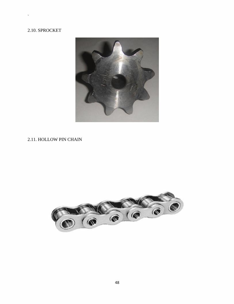
1.2.2. Hollow Pin Chain
Construction and Features:
In Hollow Pin Chain, the pin has a hole, allowing for the installation of various
attachments. Usually these chains are used for conveyors. Sizes are shown in Tables
The advantages of installing attachments into the hollow pin include the following:
1. The hollow pin is at the center of articulation, and always keeps the pitch length.
Regardless of whether the chain is straight or wrapping around the sprocket, the center
distance of attachments is always the same shows an example of installing a mesh net. Even
when the chains bend, the mesh net does not expand or contract.
Hollow Pin Chain
19

`
Installing Attachments
2. With a cross rod over two chains, the load from the attachments is distributed to both
sides of plates equally. The chain can fully use its strength and not twist.
3. It is easy to change, maintain, and adjust attachments.
Selection and Handling
1. These chains are selected using the same methods as other conveyor chains. Care
must be taken since the maximum allowable tension of hollow pin chains is less than that of
the same-sized standard chains.
2. Retaining rings are used on the pin head for connecting links. When an attachment
link is to be added to an HP connecting link, the attachment link pin must be longer than
those used in the rest of the chain.
3. The pin is not riveted in this chain. The lower maximum allowable load and the high
rigidity of the pin make it difficult for the link plates to come off.
4. The small pitch series and the S-roller (standard) types in the double pitch series are
bushing chains, which do not have rollers.
Chain No. Pitch
(mm)
Pin Minimum Inner Diameter
(mm)
Maximum Allowable Load
(kN)
20

`
RS40HP 12.70 4.00 1.76
RS50HP 15.875 5.12 3.14
RS60HP 19.05 5.99 4.21
RS80HP 25.40 8.02 7.64
RF2040HP 25.40 4.00 1.76
RF2050HP 31.75 5.12 3.14
RF2060HP 38.10 5.99 4.21
RF2080HP 50.80 8.02 7.64
1.2.3. Sprockets:
A sprocket is a profiled wheel with teeth that meshes with a chain, track or other perforated or
indented material. It is distinguished from a gear in that sprockets are never meshed together
directly, and differs from a pulley in that sprockets have teeth and pulleys are smooth.
21

`
Do = Sprocket Diameter
Dp = Pitch Diameter
Procedure for Laying Out a Sprocket:
The dimensions of a sprocket can be calculated as follows, where P is the pitch of the
chain, and N is the number of teeth on the sprocket;
Pitch Diameter = P ÷ sin (180° ÷ N)
Outside Diameter = P × (0.6 + cot ( 180° ÷ N) )
Sprocket thickness = 0.93 × Roller Width - 0.006"
The first thing you need to know to lay out a sprocket is the dimensions of the chain
which is to run upon it, specifically the pitch, roller diameter, and the roller width of the chain.
The second thing you need to know is the number of teeth in the sprocket, which will depend
entirely on your application. From these numbers, the outside diameter and thickness of the
required blank can be calculated.
22

`
You'll also need to know the angle between teeth - this is simply the 360° divided by the
number of teeth.
1. Start by drawing
three radial lines from
the center of the b
to the edge, separat
by an angle equal to
the angle between
teeth.
lank
ed
2. Draw lines parallel
to these lines, at a
distance equal to the
pitch of the chain.
23

`
3. A roller will be
located at each
intersection of the
parallel lines and the
pitch circle. Draw a
circle equal to the
roller diameter of the
chain.
4. Draw lines b
the roller centers.
etween
24

`
5. Draw circles
around the roller
centers that pass
through the
intersection of the
other roller and the
line between centers.
6. The tooth profile is
as shown.
The sprocket teeth are usually truncated one chain pitch above the bottom of the seat; this
is not shown here. Note that this shape is not the only one that will work - bicycles in particular
use various tooth shapes for different circumstances.
Application
Sprockets should be accurately aligned in a common vertical plane, with their axes
parallel. Chain should be kept clean and well lubricated with thin, light-bodied oil that will
penetrate the small clearances between pins and bushings.
25

`
Center distance should not be less than 1.5 times the diameter of the larger sprocket, nor
less than 30 times the chain pitch, and should not exceed 60 times the chain pitch. Center
distance should be adjustable - one chain pitch is sufficient - and failing this an idler sprocket
should be used to adjust tension. A little slack is desirable, preferably on the bottom side of the
drive.
The chain should wrap at least 120° around the drive sprocket, which requires a ratio of
no more than 3.5 to 1; for greater ratios, an idler sprocket may be required to increase wrap
angle.
1.3 Manufacturing Processes:
1.3.1 Bending With Power Press brakes:
Bending is a process by which metal can be deformed by plastically deforming the
material and changing its shape. The material is stressed beyond the yield strength but below the
ultimate tensile strength. The surface area of the material does not change much. Bending usually
refers to deformation about one axis.
Bending is a flexible process by which many different shapes can be produced. Standard
die sets are used to produce a wide variety of shapes. The material is placed on the die, and
positioned in place with stops and/or gages. It is held in place with hold-downs. The upper part
of the press, the ram with the appropriately shaped punch descends and forms the v-shaped bend.
Bending is done using Press Brakes. Press Brakes normally have a capacity of 20 to 200
tons to accommodate stock from 1m to 4.5m (3 feet to 15 feet). Larger and smaller presses are
used for specialized applications. Programmable back gauges, and multiple die sets available
currently can make for a very economical process.
26

`
1.3.2. Electric Gas Welding:
Electro gas welding (EGW) is a continuous vertical position arc welding process
developed in 1961, in which an arc is struck between a consumable electrode and the work piece.
A shielding gas is sometimes used, but pressure is not applied. In EGW, the heat of the welding
arc causes the electrode and work pieces to melt and flow into the cavity between the parts being
welded. This molten metal solidifies from the bottom up, joining the parts being welded together.
The weld area is protected from atmospheric contamination by a separate shielding gas, or by the
gas produced by the disintegration of a flux-cored electrode wire.
Electro-gas welding can be applied to most steels, including low and medium carbon
steels, low alloy high strength steels, and some stainless steels. Quenched and tempered steels
may also be welded by the process, provided that the proper amount of heat is applied. Welds
must be vertical, varying to either side by a maximum of 15 degrees.
27

`
Welding Machine Oxy-Acetylene Cutting
1.3.3. Oxy Acetylene cutting process:
The oxy-fuel process is the most widely applied industrial thermal cutting process
because it can cut thicknesses from 0.5mm to 250mm, the equipment is low cost and can be used
manually or mechanized. There are several fuel gas and nozzle design options that can
significantly enhance performance in terms of cut quality and cutting speed.
28

`
Process Fundamentals:
Basically, a mixture of oxygen and the fuel gas is used to preheat the metal to its 'ignition'
temperature which, for steel, is 700°C - 900°C (bright red heat) but well below its melting point.
A jet of pure oxygen is then directed into the preheated area instigating a vigorous exothermic
chemical reaction between the oxygen and the metal to form iron oxide or slag. The oxygen jet
blows away the slag enabling the jet to pierce through the material and continue to cut through
the material.
1.3.4. Radial Drilling:
This machine is very useful because of its wider range of action. Its principal use is in
drilling holes on such work which is difficult to be handled frequently. With the use of this
machine, the tool is moved to the desired position instead of moving the work to bring the latter
in position for drilling.
29

`
Radial Drilling Machine Threading die
1.3.5. Threading:
Cutting threads on a steel rod requires a die set. A cutting die is the sister tool of a tap. A
tap cuts threads into material, and a die cuts threads around material. When the threads are cut
correctly, a hex nut will thread onto the threaded section of the steel rod. This allows you to use
the threaded steel rod as a structural fastener or spacer. Rushing through the threading process
can create unusable threads that will not accept a nut.
Instructions for Threading:
Secure the steel rod into a bench-mounted vise with one end of the steel rod pointed
toward the ceiling.
Insert a blade of a thread gauge inside of the hex nut. If the V-notches of the thread gauge
blade do not match the inside threads of the hex nut, flip out and check the nut with
another blade. When you find a blade that matches the hex nut threads exactly, read the
size and thread count stamped in the side of the blade.
30

`
Select a die from a die set that matches the size stated on the thread gauge blade.
Insert the flat side of the die into the socket of the die wrench. Tighten the thumb screws
located on either side of the socket with your fingers to secure the die in the die wrench.
Apply cutting fluid to the interior cutting threads of the die and the surface of the steel
rod.
Set the die onto the end of the steel rod. Hold both handles of the die wrench with your
hands. Apply pressure toward the end of the steel rod as you turn the die wrench
clockwise for right-hand threads or counterclockwise for left-hand threads. Keep the die
wrench square to the steel rod as you turn to ensure the threads cut square.
Turn the die wrench 1/2 turn in the reverse when you feel the die wrench becoming
harder to turn. Apply additional cutting fluid to the die cutting threads and continue
cutting thread on the steel rod.
Reverse the direction you are turning the die wrench to remove the die from the steel rod
when you have threads cut to your required length.
Wipe the threads with a clean rag to remove metal shavings from the steel rod.
2. MODELLING
CAD software used – Pro/E V5
31

`
2.1. PLATFORM ASSEMBLY
32

`
33

`
234

`
.2. PLATFORM
35

`
36

`
2.3. L SHAPE ROD
37

`
38

`
2.4. SQUARE ROD
39

`
40

`
2.5. BEAM
41

`
42

`
2.6. U CLAMP
43

`
44

`
2.7. BUSH
45

`
46

`
2.8. 8MM ID BEARING
7 – 8MM ID BEARING
ALL DIMENSIONS ARE IN MM
47
`
2.10. SPROCKET
2.11. HOLLOW PIN CHAIN
48

`
Pitch Width Roller Plate Pin P W Dia Height Thickness Dia Lengths
MAXTOP CHAIN NO.
(ANSI) inch mm mm R H1 H2 T1 T2 D d(min) F G
Average Ultimate Strength
kgf
Approx Weight
kg/m
40HP 1/2" 12.70 7.94 7.92 10.20 11.80 1.50 1.50 5.58 4.00 7.90 9.4 1300 0.5 50HP 5/8" 15.875 9.53 10.16 13.00 14.80 2.00 2.00 7.01 5.12 9.90 11.65 2000 0.8 60HP 3/4" 19.05 12.70 11.91 15.50 17.50 2.40 2.40 8.12 5.99 12.40 14.25 3050 1.18 80HP 1" 25.40 15.88 15.88 20.80 24.00 3.10 3.10 11.27 8.02 16.30 17.75 5800 2.10
08BHP 1/2" 12.70 7.75 8.51 10.60 11.80 1.50 1.50 6.11 4.50 8.20 9.30 1500 0.63
49

`
2.12. ASSEMBLY OF THE PARKING SYSTEM
50

`
51

`
3. MANUFACTURING OF THE PARTS
When it comes to the manufacturing, some more parts are added which were not shown in
the Design, some parts are modified from the designs mentioned before. These addition and
modifications are done taking account into various factors such as
Lack of availability of very small readymade parts because of the scaling of model
To reduce overall cost without compromising in its performance
To increase overall strength
To attain maximum strength with the available resources
3.1. Platform:
Manufacturing of platform was first started with bending a 3 mm thick mild steel sheet of
size 345*228mm using a power press and is obtained as shown in the fig.
The shape we shown here can also be obtained by welding the pieces of MS sheets but
the strength will be doubled when it is bended rather than welded, so we went for bending a
3mm sheet which is quite good enough to carry low and medium loads and is very good enough
in its strength to carry any type of scaled cars in this model.
It is our responsibility to deliver the car in the same condition as when it is loaded into
the platform, so we have to protect the car body from the unexpected leakages of oil from the
engine which is vertically above it, for this to drain the oil directly onto the ground we shaped
the front edges of the platform in such a way that engine comes over it and any leakages will be
drained without affecting the platform under it.
52

`
Platform has to be supported into the sprockets which are attached to the structure, to do
this, platform is welded with plates which already has drilled holes to carry the angled rods
which in turn carries a square rod.
53

`
3.2. Angled rods for Platform:
This part is especially manufactured to attach the platform base to the rods which are
attached to the sprocket. A ‘J’ screw of 6.6mm diameter is taken and is straightened; the screw is
then bent to right angle so that the platform will in remain vertical position. A screw is has been
chosen because the height of platform can be adjusted with the help of the nut provided for the
screw.
3.3. Square Rods for Platform: 54

`
A Square rod of mild steel of length 120 mm and thickness 16mm is taken. On the side of
the rod, a through hole of 10mm diameter is drilled on the lathe for the rod to pass through it. On
the other two sides of square rod, a hole of 6.6 diameter on each side of length equal to smaller
side of angled rod is made so that angled rod is fixed into these holes .This can be best
understood by following photographs:
55

`
3.4. Sprockets: 56

`
A total of 12 sprockets are taken, 6 on each side for the chain to move on it.
c
Driving Sprocket:
Four holes of size M6 are drilled on the right angels of the driving sprocket and later two pin
holes of 6 diameter are made on the sprocket .The sprocket is attached to motor by means of an
adaptor. Pin holes are made to transmit the power and M6 holes are made to hold the adaptor in
it.
Driven Sprockets:
All the remaining 11 sprockets are driven sprockets. The driven sprockets are bored to
increase the internal diameter of the sprockets, so that two bearings can be seated on both edges
of the sprocket. These two bearings are held in position by placing a spacer between the two
bearings. These driven sprockets are attached to frame by a placing a stud passing through these
two bearings and through the hole in the frame and are held firmly by placing a double nut at its
ends.
3.5. Platform Assembly:
57

`
58

`
The angled rods are inserted into the holes of the platform, the holes are made in such a way
that the angled rods will be at 30 degrees with the platform horizontal. The opposite ends of each
angled rod are inserted into side holes of the square rod having 6.6 diameter holes. A 10mm rod
of 480 length is inserted into the holes of square rods which has assembly to attach this into
sprocket.
Motor:
We are going to use a ¼ th HP brake motor with induction , which can move the platforms in
both clockwise and anticlockwise direction.
Frame:
We are going to use angle plates with slotted holes to build up the frame and different pieces
are to be cut and welded to form the required structure which could support the platforms,
Chains, sprockets providing a provision to place the motor.
59

`
4. Advantages:
Quick Automated Parking and retrieval of vehicles.
Up to 12 cars or 10 SUV's can be easily and safely parked.
Surface space required equivalent to just 2 surface car parking spaces.
Most suitable for Staff or dedicated user parking.
Engineered to ensure Driver safety by use of an electronic Safety zone.
Low maintenance levels required by the system.
Does not require a parking attendant.
Easily constructed in a small area, just requiring a simple concrete base and 3 phase
electricity.
This system is cost effective when extra land for surface parking is not available.
Rotary parking is extremely reliable and has been well tried and tested with many
reference sites available.
It can be built-in turntable in the system.
60

`
5. Benefits: Imagine the time that automatic smart parking systems would save you. Every
time you enter your office building you have to find a parking space and spend time
walking in and out of the lot as well. Imagine how much time it is costing you. Even if
you just spend 5 minutes a day to park that translates to you spending more than a whole
day just parking every year. If you calculate the time you spend walking in and out of the
parking lot, searching for space and such it will be easily more than the above amount.
A fully automated system mimics a futuristic assembly line structure where the
cars are moved to an empty platform. The platform under the car moves to a designated
spot and all the other platforms are arranged so that no cars are stuck. You are able to
keep track of the entire structure and spend virtually no time driving the car in the
parking you. You simply drop off the car at the entrance and pick up on your way out.
Aside from the comfort that the automation
brings you can also save space through incorporating
the park lift system as well. Through this we are able to
utilize the vertical space in a parking lot that is usually
wasted. You are also able to customize each stack
parker so that you can fit different sized cars in each of
the different slots. It would be meaningless to have all
stack parkers adjusted to the height of a SUV when you
can have different sets where you can park 2 SUVs or 3 regular sedans.
61

`
6. Conclusion: Our Smart Car Parking model has been designed; all the parts in it are manufactured and
we are under assembly which will be completed soon. Analysis of the model has to be done
when developing a life size model. As the life cycle model involves huge money, proper
design and advanced methods are to be used to meet the requirements of the customers.
Although we developed working model of the original one, we tried maximum to develop
a replica of original and we were compromised only in those stages where the work cannot
be completed by assuming or neglecting few factors.
7. Future work: This automated car parking system can be installed with safety installations such as,
whenever there is human movement in the system, the rotation of the platforms should be
immediately stopped.
The platforms can also be equipped with safety sensors guiding the movement of vehicles
in the platforms.
It can be fully automated by integrating it with a panel board, such that whenever a
particular number is called on the panel board, the respective platform should appear at
the ground level.
This calling can also be made more secured by providing each platform a specific
password, so that only whenever a particular password is typed the platform is retrieved.
It can also be programmed, so that the platforms travel the minimum distance in the
retrieval of the vehicle.
A turn table can be incorporated with the system in front of the ramp of platform so that
cars can be easily turned and parked into the platform. This is very useful in the areas
where cars cannot turn easily to get into the platform.
62

`
Bibliography
Links:
http://www.gizmology.net/sprockets.htm
http://aboutstrangesorld.blogspot.com/2010/07/10‐automated‐car‐parking‐
systems.html
http://www.parkingsystemsolutions.com/rotary/
http://www.chain‐manufacturer.com/stainless‐steel‐conveyor‐chain.html
http://chain‐guide.com/applications/2‐1‐4‐hollow‐pin‐chain.html
http://www.tksmy.com/activities_parking_system.html
http://www.dimts.in/Engineering_Services.htm
http://twistedphysics.typepad.com/cocktail_party_physics/2007/12/where-to-
park-i.html
http://en.wikipedia.org/wiki/Sprocket
Books:
Theory of Machines by S.S.Rattan
Production Technology by R.K.Jain
63