
IVAR Tech Data Sheet - cbsupplies.ca
4
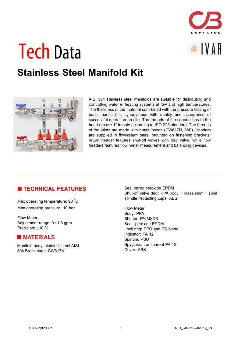
Stainless Steel Manifold Kit AISI 304 stainless steel manifolds are suitable for distributing and controlling water in heating systems at low and high temperatures. The thickness of the material com-bined with the pressure testing of each manifold is synonymous with quality and as-surance of successful operation on site. The threads of the connections to the head-ers are 1” female according to ISO 228 standard. The threads of the joints are made with brass inserts (CW617N, 3/4”). Headers are supplied in flow/return pairs, mounted on fastening brackets: return header features shut-off valves with disc valve, while flow headers features flow meter measurement and balancing devices. TECHNICAL FEATURES Max operating temperature: 90 ◦ C Max operating pressure: 10 bar Flow Meter Adjustment range: 0 : 1.3 gpm Precision: ±10 % MATERIALS Manifold body: stainless steel AISI 304 Brass parts: CW617N Seal parts: peroxide EPDM Shut-off valve disc: PPA body + brass stem + steel spindle Protecting caps: ABS Flow Meter Body: PPA Shutter: PA MXD6 Seal: peroxide EPDM Lock ring: PPO and PS blend Indicator: PA 12 Spindle: PSU Spyglass: transparent PA 12 Cover: ABS Tech Data CB Supplies Ltd 1 ST I_CI586C-CI589C_EN
Transcript of IVAR Tech Data Sheet - cbsupplies.ca
Stainless Steel Manifold Kit
AISI 304 stainless steel manifolds are suitable for distributing and controlling water in heating systems at low and high temperatures. The thickness of the material com-bined with the pressure testing of each manifold is synonymous with quality and as-surance of successful operation on site. The threads of the connections to the head-ers are 1” female according to ISO 228 standard. The threads of the joints are made with brass inserts (CW617N, 3/4”). Headers are supplied in flow/return pairs, mounted on fastening brackets: return header features shut-off valves with disc valve, while flow headers features flow meter measurement and balancing devices.
� TECHNICAL FEATURES
Max operating temperature: 90 ◦CMax operating pressure: 10 bar
Flow MeterAdjustment range: 0 : 1.3 gpm Precision: ±10 %
� MATERIALSManifold body: stainless steel AISI 304 Brass parts: CW617N
Seal parts: peroxide EPDMShut-off valve disc: PPA body + brass stem + steel spindle Protecting caps: ABS
Flow MeterBody: PPAShutter: PA MXD6Seal: peroxide EPDMLock ring: PPO and PS blendIndicator: PA 12Spindle: PSUSpyglass: transparent PA 12Cover: ABS
Tech Data
CB Supplies Ltd 1 ST I_CI586C-CI589C_EN
gilles.legault
Cross-Out

� DIMENSIONS
Manifold kit 1”×EK with brackets, flow balancing/metering devices and return shut-off valves suitable to thermostatic or manual control.
S
R
T
G
A
CF H
NM
F H B
G
CI 589C - Dimensions and product codes
Loops Part No. SIZE A B C D F G H M N P R S T
2
1”
130
3/4” 3/4” - 40 1” 50 44 85 - 200 32 100
3 1804 2305 2806 3307 3808 4309 48010 53011 58012 630
CB Supplies Ltd 2 ST I_CI586C-CI589C_EN
763510002-S763510003-S763510004-S763510005-S763510006-S763510007-S763510008-S763510009-S763510010-S763510011-S763510012-S

� HYDRAULIC FEATURES
Flow manifold (single way) Return manifold (single way)
kPa
100
80
60
40
20
9
7
5
3
1
0.8
0.6
0.4
0.2
90
70
50
30
10
8
6
4
2
0.9
0.7
0.5
0.3
0.1
P
mbar
900
700
500
300
100
80
60
40
20
9
7
5
3
1
1000
800
600
400
200
90
70
50
30
10
8
6
4
2
qm = kg/h
10
30
50
70
90
20
40
60
80
100
300
500
700
900
200
400
600
800
1000 2000
3000
Kvs = 1.16
FLUXER
kPa
100
80
60
40
20
9
7
5
3
1
0.8
0.6
0.4
0.2
90
70
50
30
10
8
6
4
2
0.9
0.7
0.5
0.3
0.1
P
mbar
900
700
500
300
100
80
60
40
20
9
7
5
3
1
1000
800
600
400
200
90
70
50
30
10
8
6
4
2
qm = kg/h
10
30
50
70
90
20
40
60
80
100
300
500
700
900
200
400
600
800
1000 2000
3000
Kvs = 2.5
� OPERATING INSTRUCTIONS
AdjustmentFlow meter devices allow the adjustment and the balancing of each outtake and keep memory of the selected position in case of temporary closure due to maintenance operations. In order to perform a correct adjustment, proceed as follows:
1. Remove the orange cover as in Fig.1-A;
2. Set the Flow meter in closure position by turning the upper lock ring in the direction indicated by the arrow in Fig.1-B; NB: in closure position, the indicator points a null flow-rate;
3. Open the device by turning the same lock ring in the opposite direction (Fig.1-C), and check the correct flow rate through the spyglass;
4. Screw the lower lock ring in the direction indicated in Fig.1-D, until mechanical stop;
5. Put back the orange cover (Fig.1-E);
CB Supplies Ltd 3 ST I_CI586C-CI589C_EN
gilles.legault
Typewritten Text
Manifold Cv factor = 3.2
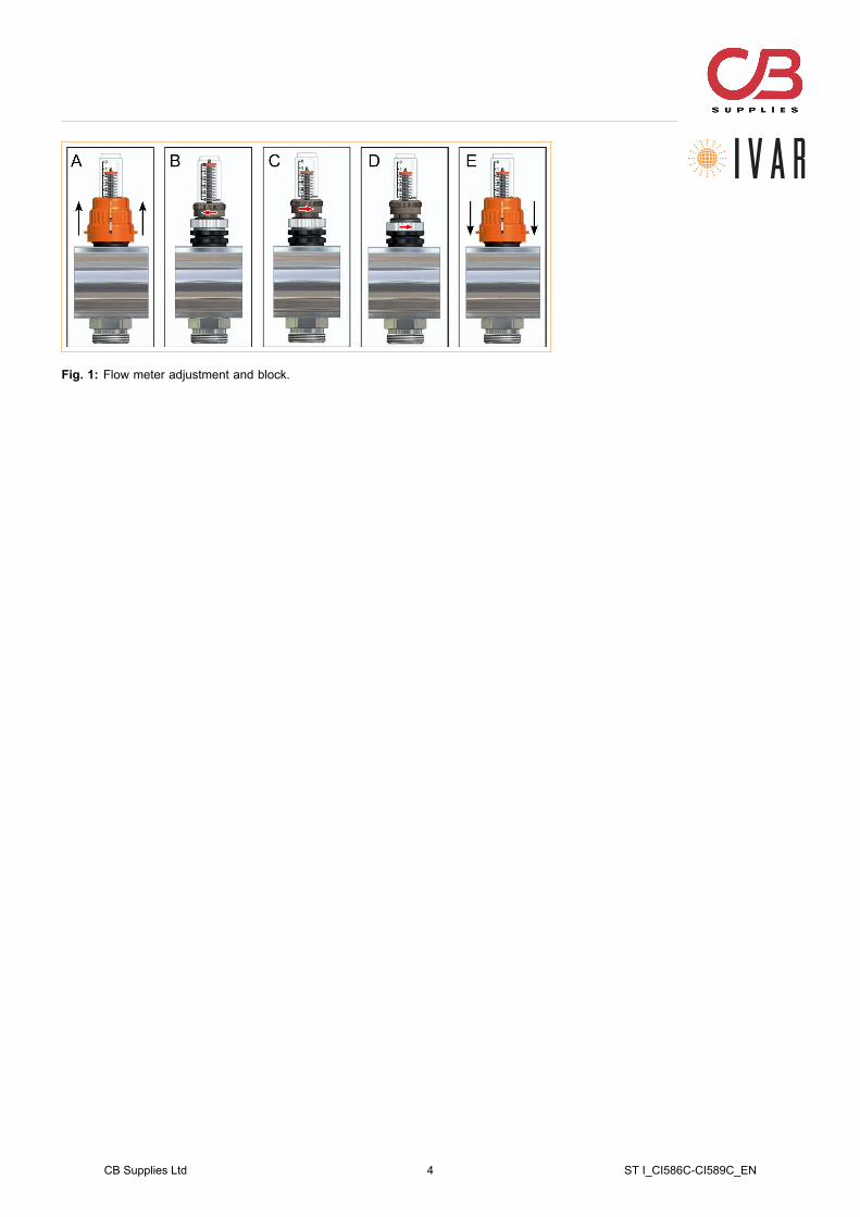
Fig. 1: Flow meter adjustment and block.
CB Supplies Ltd 4 ST I_CI586C-CI589C_EN