ITU/ITSO Arab Regional Training on VSAT and … · Access schemes 1/13 • The methods by which...
70
Day 2, Session 2: Satellite Network Topologies Presenter: E. Kasule Musisi ITSO Consultant Email: [email protected] Cell: +256 772 783 784 ITU/ITSO Arab Regional Training on VSAT and Satellite Systems: Broadband services over Satellite, Sultanate of Oman, Muscat, March 13-17, 2016 1
Transcript of ITU/ITSO Arab Regional Training on VSAT and … · Access schemes 1/13 • The methods by which...

Day 2, Session 2:
Satellite Network Topologies
Presenter: E. Kasule Musisi
ITSO Consultant
Email: [email protected]
Cell: +256 772 783 784
ITU/ITSO Arab Regional Training on VSAT and Satellite Systems: Broadband
services over Satellite, Sultanate of Oman, Muscat, March 13-17, 2016
1

2
1. Satellite Network Topologies
2. Access Schemes (FDMA, TDMA, DAMA, PAMA etc)
3. C-Band vs Ku-Band
4. VSATs and Data Communications
5. Digital Communication Techniques
Protocols e.g., TCI/IP, Frame Relay
Compression
VoIP
6. Modulation (AM, PSK , FSK , CDMA)
7. Understanding Link Budget Analysis
Topics in this Module

Satellite Network Topology 1/9
Satellites networks have various topologies. We can enumerate the following :
• Star Networks
• Mesh Networks
• SCPC
3

Satellite Network Topology2/9
Star Network
Common used for data networks
• It involves a Hub Station and Remotes. All the channels are shared and
the remote terminals are online, offering fast response times.
• All the traffic goes through the Hub station
• Use capacity on a TDM/TDMA basis
4

Satellite Network Topology3/9
Star Network
5
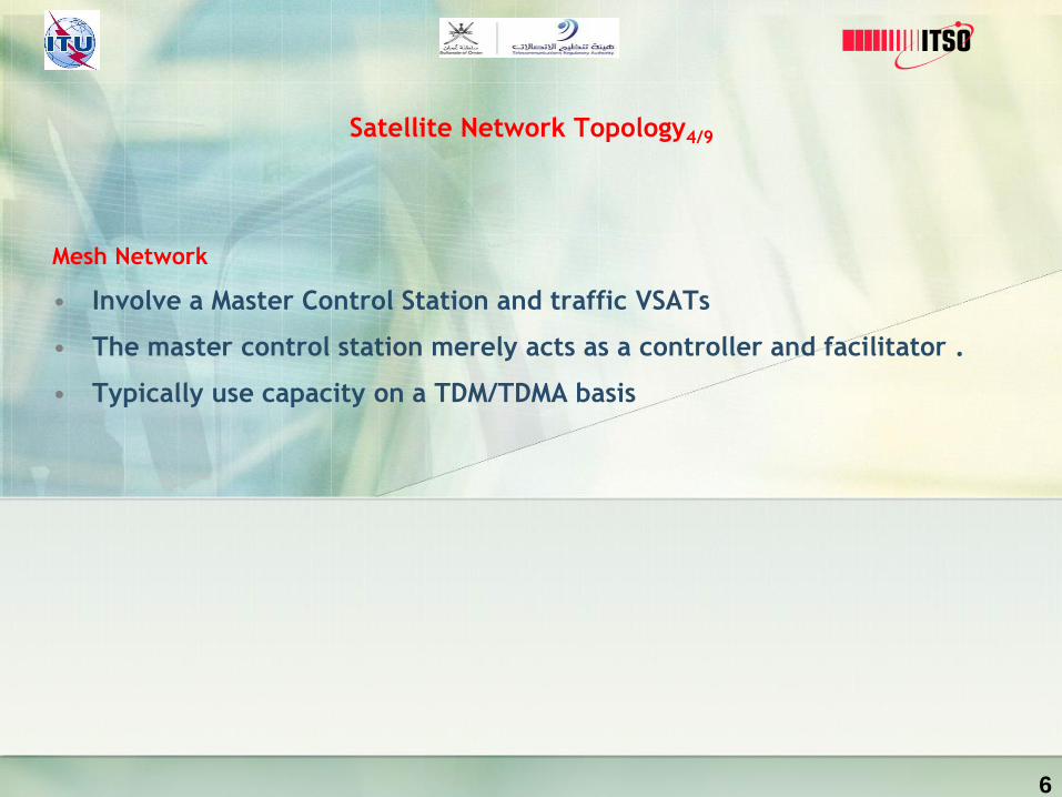
Satellite Network Topology4/9
Mesh Network
• Involve a Master Control Station and traffic VSATs
• The master control station merely acts as a controller and facilitator .
• Typically use capacity on a TDM/TDMA basis
6

Satellite Network Topology5/9
Mesh Network
7

Satellite Network Topology6/9
Mesh Network
There are also mesh systems which use a TDMA access scheme where all
of the terminals in a network receive and transmit to the same channel,
selecting different time slots because each terminal is aware of what the
others have reserved.
8

Satellite Network Topology 7/9
SCPC Network
• Point-to-point SCPC (single channel per carrier) links are the satellite
equivalent of a terrestrial leased line connection.
• They are usually set-up on a permanent, 24 hour basis and are thus
more costly in satellite capacity and less efficient if not used all the
time. However, they do support dedicated high bandwidth links
without any sharing or contention. .
9

Satellite Network Topology 8/9
SCPC Network
10

Satellite Network Topology 9/9
Other Network Topologies
All other systems are usually a variation on one of the themes described
above, either in a star, mesh or hybrid (star and mesh) configuration. Most
of the TDM/TDMA manufacturers also offer a mesh product which can be
deployed in a hybrid-ised configuration, sharing common components such
as antennas and RF units, at a remote site.
11

Access schemes1/13
• The methods by which VSAT networks optimize the use of satellite
capacity, and spectrum utilization in a flexible and cost-effective manner
are referred to as satellite access schemes.
• Each topology is associated with an appropriate satellite access scheme.
Good network efficiency depends very much on the multiple access
schemes.
• Examples of Access Schemes discussed in this Module are: SCPC, TDMA,
FDMA, DAMA, CDMA
12
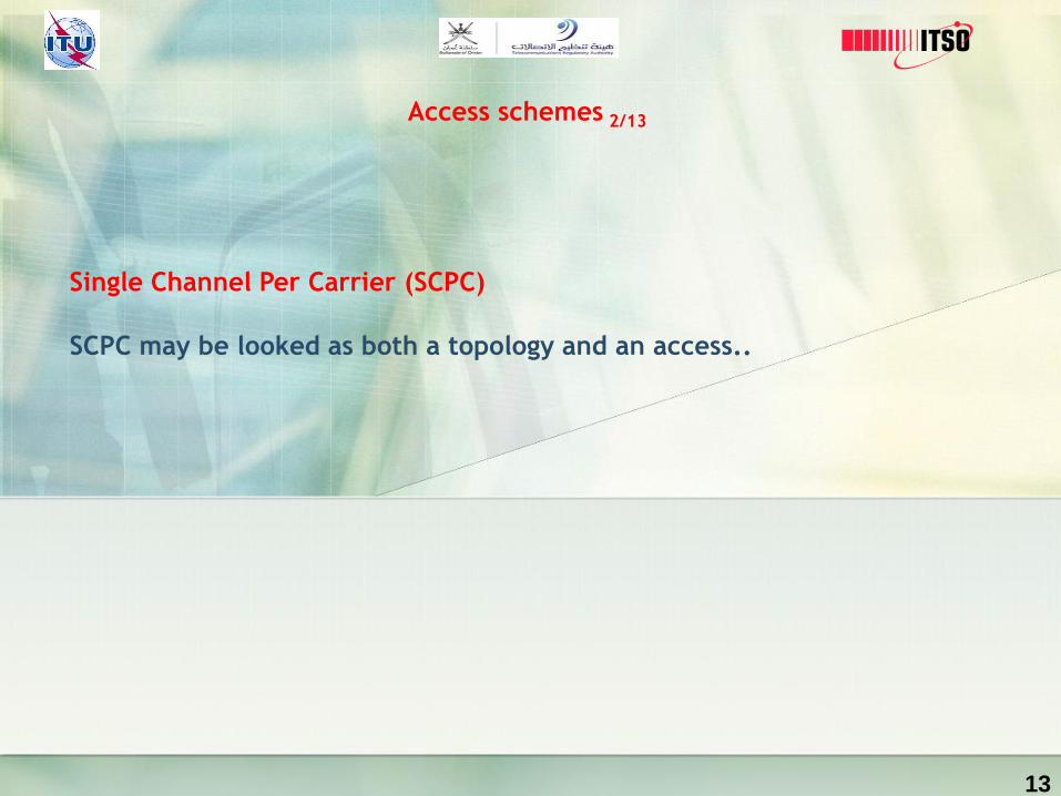
Access schemes 2/13
13
Single Channel Per Carrier (SCPC)
SCPC may be looked as both a topology and an access..

Access schemes3/13
SCPC
SCPC satellite backbone connectivity provides constant dedicated
communications to deliver one way, full duplex or asymetrical service in point
to point, point to multi-point, star, mesh, or hybrid network configurations.
In these designs, an SCPC network can deliver high bandwidth to easily
support the most demanding service applications, such as, video-conferencing,
voice communications, and data transmission. Dedicated bandwidth
connectivity is offered on SCPC, iSCPC, DVB and DVP-S2 platforms.
14

Access schemes4/13
SCPC
Important Satellite SCPC features
• Supports true multimedia capabilities - voice,video,data
• Replacement of terrestrial circuits
• Backup circuits for redundancy or diversity
• Remote access where high-speed terrestrial connectivity isn't available
Potential SCPC applications
• High-speed access to IP networks
• Replacement of terrestrial circuits
• Credit authorizations and inventory management
• Corporate operations and account management
• WAN connectivity
15

Access schemes5/13
SCPC
Point-To-Point Dedicated
Depending upon the satellite and provider, some links can deliver high
speeds of up to 155Mbps which is comparable to a terrestrial leased
line connection.
16

Access schemes6/13
SCPC
These networks easily support voice, video, and data transmissions
utilizing a standard data/voice multiplexer, an SCPC satellite modem,
and a VSAT terminal at each site. This is a very simple approach for
point-to-point networks as communications are only between the two
sites. Similarly, Point-To-MultiPoint satellite connectivity is a network
configuration composed of multiple Point-To-Point SCPC connections.
There is no connectivity to the teleport which requires the satellite
signal to make a double hop. More important, the quality of real time
applications is not affected.
There are no costs associated with the usage of a teleport or backhaul
which makes this a less expensive solution
17

Access schemes7/13
TDMA
• Numerous remote sites communicate with one central hub
• Remote sites in a TDMA network compete with one another for access to
the central hub, restricting the maximum available bandwidth.
• All VSATs share satellite resource on a time-slot basis.
• Remote VSATs use TDMA channels or in routes for communicating with the
hub. There could be several inroutes associated with one outroute. Several
VSATs share one inroute hence sharing the bandwidth. Typical inroutes
operate at 64 or 128 Kbit/s.
18

Access schemes8/13
TDMA
19

Access schemes 9/13
FDMA
Here, all VSATs share the satellite resource on the frequency domain only.
Typically implemented in a mesh or single satellite hop topology.
FDMA has the following variants:
• PAMA (Pre-Assigned Multiple Access)
• DAMA (Demand Assigned Multiple Access)
• CDMA (Code Division Multiple Access)
20

Access schemes10/13
PAMA
VSATs are pre-allocated designated frequencies.
PAMA solutions use the satellite resources constantly. Consequently, there is
no “call-up” delay what makes them most suited for interactive data
applications or high traffic volumes. As such, PAMA connects high data traffic
sites within an organization.
21
Access schemes11/13
DAMA
The network uses a pool of satellite channels, which are available for use by
any station in that network. On demand, a pair of available channels is
assigned so that a call can be established..
22
Access schemes12/13
CDMA
Under this access scheme, a central network monitoring system allocates a
unique code to each of the VSATs enabling multiple VSATs to transmit
simultaneously and share a common frequency band. To permit this to be
achieved without undue interference between the users CDMA employs
spread-spectrum technology.
23

Access schemes13/13
24

Questions so far?
25

C Band vs. Ku Band 1/4
C Band: For satellite communications, the microwave frequencies of the C-
band perform better in comparison with Ku band (11.2 GHz to 14.5 GHz)
microwave frequencies, under adverse weather conditions, which are used by
another large set of communication satellites. The adverse weather conditions
all have to do with moisture in the air, such as during rainfalls,
thunderstorms, sleet storms, and snowstorms.
• Downlink: 3.7 – 4.2 GHz
• Uplink: 5.9 – 6.4 GHz
26

C Band vs. Ku Band 2/4
C Band
27
`C-Band Variations Around The World
BandTransmit Frequency
(GHz)
Receive Frequency
(GHz)
Extended C-Band 5.850–6.425 3.625–4.200
Super Extended C-Band 5.850–6.725 3.400–4.200
INSAT C-Band 6.725–7.025 4.500–4.800
Russian C-Band 5.975–6.475 3.650–4.150
LMI C-Band 5.7250–6.025 3.700–4.000

C Band vs. Ku Band 3/4
Ku Band
The Ku band is a portion of the electromagnetic spectrum in the microwave
range of frequencies. This symbol refers to "K-under" (in the original German,
"Kurz-unten", with the same meaning)—in other words, the band directly
below the K-band. In radar applications, it ranges from 12 to 18 GHz according
to the formal definition of radar frequency band nomenclature in IEEE
Standard 521-2002.
• Downlink: 11.7 – 12.2 GHz
• Uplink: 14.0 – 14.5 GHz
28
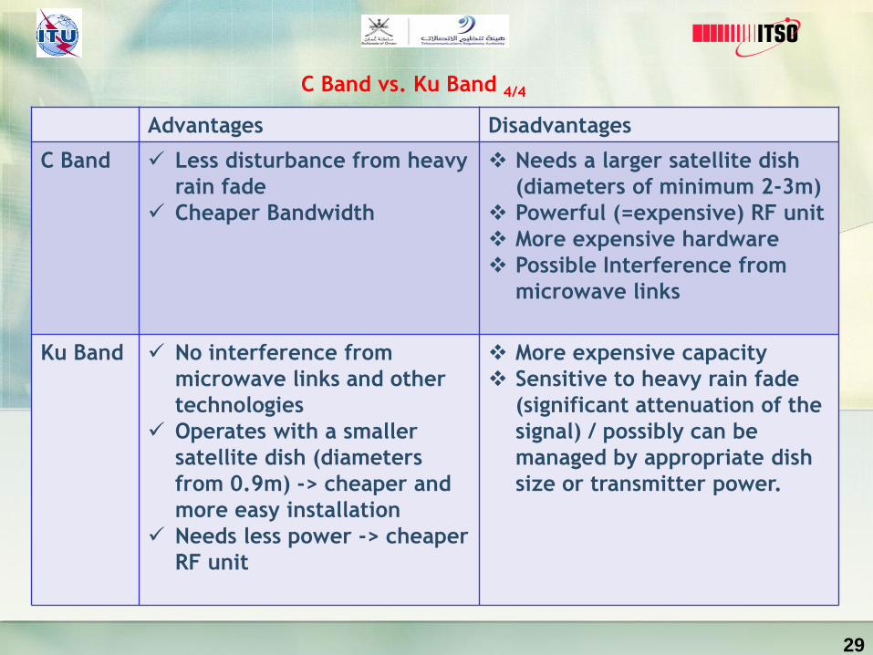
C Band vs. Ku Band 4/4
29
Advantages Disadvantages
C Band Less disturbance from heavy
rain fade
Cheaper Bandwidth
Needs a larger satellite dish
(diameters of minimum 2-3m)
Powerful (=expensive) RF unit
More expensive hardware
Possible Interference from
microwave links
Ku Band No interference from
microwave links and other
technologies
Operates with a smaller
satellite dish (diameters
from 0.9m) -> cheaper and
more easy installation
Needs less power -> cheaper
RF unit
More expensive capacity
Sensitive to heavy rain fade
(significant attenuation of the
signal) / possibly can be
managed by appropriate dish
size or transmitter power.
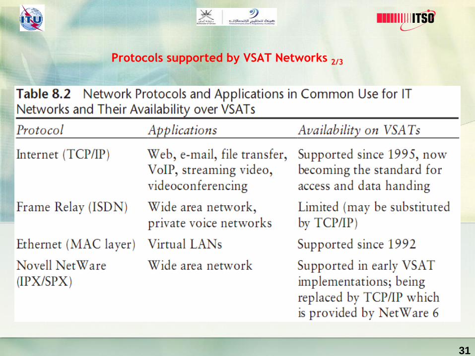
Protocols supported by VSAT Networks 1/3
A summary of the protocols in general use and their support over
typical VSAT networks is provided in Table 8.2.
While still in existence in some legacy environments, it has been
replaced with the more open Internet Protocol suite (TCP/IP).
30
31
Protocols supported by VSAT Networks 2/3

Protocols supported by VSAT Networks 3/3
Frame Relay
Frame Relay has been popular in WANs for more than a decade, thanks to its
ease of interface at the router and availability in (and between) major
countries.
It is capable of near-real-time transfer and can support voice services. With
access speeds generally available at 2 Mbps or less.
Satellite provision of Frame Relay has been limited to point-to-point circuits
as the protocol is not directly supported in VSATs currently on the market.
32

Digital Communications techniques 1/??
Protocol Layering
Modern data communications theory and practice is literally built upon
the concept of protocol layering, where the most basic transmission
requirement is at the bottom and more complex and sophisticated
features are added one on top of each other.
While this concept is abstract, it is important to understanding how the
data in a network is assembled, processed, and reliably transferred
between sender and receiver.
33

The layering concept is embodied in the Open Systems Interconnection
(OSI) model shown in the figure on next page and contained in relevant
standards of the International Organization for Standardization (ISO)
and the ITU-Telecommunication Sector (ITU-T).
34
Digital Communications techniques 1/??

OSI and TCP/IP (DARPA) Model
35
IP Networks 1/3
TCP/IP Protocol
The immense influence of the Internet caused its communications protocol to
become the world standard. Almost all networks, except for the circuit-switched
networks of the telephone companies, have migrated to TCP/IP.
36
IP Networks 2/3
Multiple Layers
TCP/IP is a layered protocol, which means that after an application initiates the
communications, the message (data) to be transmitted is passed through a
number of software stages, or layers, until it actually moves out onto the wire, or
if wireless, into the air..
TCP and IP
TCP/IP is composed of two parts: TCP (Transmission Control Protocol) and IP
(Internet Protocol)..
37
IP Networks
UDP
An alternative protocol to TCP within the TCP/IP suite is UDP (User Datagram
Protocol), which does not guarantee delivery.
38

Compression 1/2
Analog Video Compression
In communications, data compression is helpful because it enables devices to
store or transmit the same amount of data in fewer bits, thus making the
transmission of the data faster and less costly .
39

Compression 2/2
Digital Video Compression
Hardware and/or software that compresses and decompresses a digital video
signal. MPEG, Windows Media Video (WMV), H.264, VC-1 and
40

Voice over Internet Protocol 1/4
What is VoIP?
Referring to voice communications over the public Internet or any packet
network employing the TCP/IP protocol suite.
VoIP also typically employs sophisticated predictive compression algorithms,
such as low delay code excited linear prediction (LD-CELP), to mitigate issues of
latency and jitter over a packet-switched network.
41

Softphone based
VoIP providers may be entirely
softphone based, which requires a
computer, phone software and
microphone and speakers (or headset)
to make and receive calls.
42
Voice over Internet Protocol 2/4

Handset based
Regular phones can be used with
many VoIP services by plugging
them into an analog telephone
adapter (ATA) provided by the
VoIP provider or purchased from a
third party. The ATA converts the
phone to IP packets. IP phones can
also be used that have built-in IP
packet support.
43
Voice over Internet Protocol 3/4
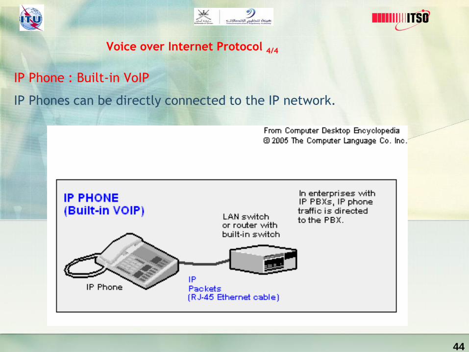
IP Phone : Built-in VoIP
IP Phones can be directly connected to the IP network.
44
Voice over Internet Protocol 4/4

Modulation 1/10
In telecommunications, modulation is the process of conveying a message
signal, for example a digital bit stream or an analog audio signal, inside
another signal that can be physically transmitted.
45
The three basic types of modulation are :
• Amplitude Shift Keying (ASK)
• Frequency Shift Keying (FSK)
• Phase Shift Keying (PSK)
All of these techniques vary a parameter of a sinusoid to represent the
information which we wish to send. A sinusoid has 3 different parameters that
can be varied. These are amplitude, phase and frequency.
46
Modulation 2/10
Amplitude Modulation (AM)
Varying the voltage of a carrier or a direct current in order to transmit analog
or digital data. Amplitude modulation (AM) is the oldest method of
transmitting human voice electronically.
47
Modulation 3/10
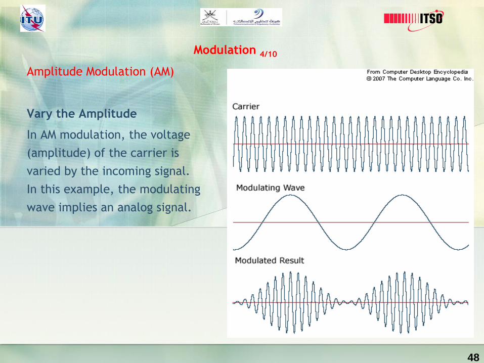
Amplitude Modulation (AM)
Vary the Amplitude
In AM modulation, the voltage
(amplitude) of the carrier is
varied by the incoming signal.
In this example, the modulating
wave implies an analog signal.
48
Modulation 4/10

Digital Amplitude Shift Keying (ASK)
For digital signals, amplitude shift
keying (ASK) uses two voltage levels
for 0 and 1 as in this example.
49
Modulation 5/10

Phase Shift Keying (PSK)
For digital signals, phase shift
keying (PSK) uses two phases for
0 and 1 as in this example.
50
Modulation 6/10

Quadrature Phase Shift Keying
(QPSK)
QPSK uses four phase angles to
represent each two bits of input;
however, the amplitude remains
constant.
51
Modulation 7/10

Frequency Shift Keying (FSK)
FSK is a simple technique that
uses two frequencies to
represent 0 and 1.
52
Modulation 8/10

Digital 8QAM
In this 8QAM example, three bits of
input generate eight different
modulation states (0-7) using four
phase angles on 90 degree boundaries
and two amplitudes: one at 50%
modulation; the other at 100% (4
phases X 2 amplitudes = 8 modulation
states). QAM examples with more
modulation states become extremely
difficult to visualize.
53
Modulation 9/10
Popular Modulation schemes used in satellite
Popular modulation types being used for satellite communications:
• Binary phase shift keying (BPSK);
• Quadrature phase shift keying (QPSK);
• 8PSK;
• Quadrature amplitude modulation (QAM), especially 16QAM.
54
Modulation 10/10

Questions so far?
55
Understanding Link Budget Analysis and Design 1/14
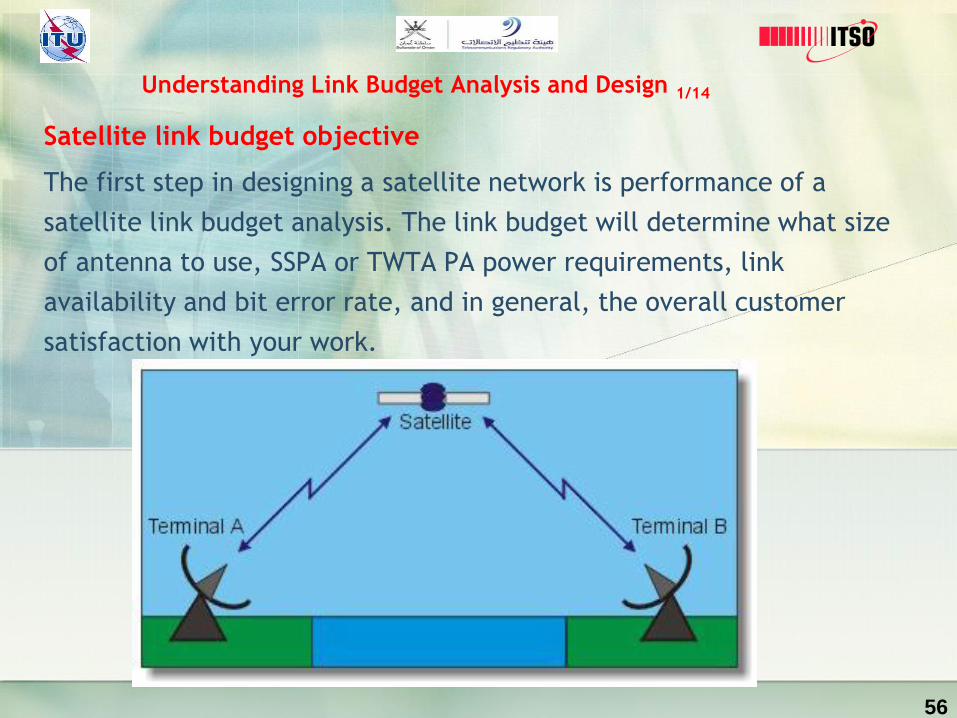
Satellite link budget objective
The first step in designing a satellite network is performance of a
satellite link budget analysis. The link budget will determine what size
of antenna to use, SSPA or TWTA PA power requirements, link
availability and bit error rate, and in general, the overall customer
satisfaction with your work.
56
A satellite link budget is a listing of all the gains and losses that will affect the
signal as it travels from the spacecraft to the ground station. After the system
has been built, the link budget is invaluable to the maintenance personnel for
isolating the cause of degraded system performance.
57
Understanding Link Budget Analysis and Design 2/14

None of the components of a link is fixed, but instead will have some variation. The
link budget must account for this. Typically the variables will be listed with a
maximum and minimum value or with a nominal value plus a tolerance. The design
engineer will allocate signal power to each variable so that the variations don't
result in unacceptable signal fade. It is usually too expensive to build a system that
will work with the worst case scenario for all variables, so it is the engineer's job to
find an acceptable balance between cost and link availability. The maintenance
engineer must also be aware of the variations so that he can properly differentiate
between expected link degradation and a link failure.
58
Understanding Link Budget Analysis and Design 3/14
Understand Link budget
The satellite link is composed of many variables and it's important to understand
when specific variables need to be included and when they can be ignored. In this
tutorial we will discuss the most common variables and provide guidelines to help
determine when they can be ignored.
The first variable in our link budget will be the spacecraft EIRP. This is the power
output from the spacecraft. All other variables will be gains or losses that will be
added or subtracted from the EIRP. Variations in the EIRP are normally pretty small
and can be ignored by the maintenance engineer once the nominal EIRP is known.
There may be small variations due to temperature and a larger change can be
expected if the spacecraft configuration is changed, such as switching to a backup
HPA.
59
Understanding Link Budget Analysis and Design 4/14

Path loss (Lpath) is the amount of signal attenuation due to the distance
between the satellite and the ground station. This is the largest loss in the
link. For example, the path loss for an S band signal from a geosyncronous
satellite will be about 192 dB. Path loss varies with distance and frequency.
The greater the distance, the greater the path loss. Higher frequencies suffer
more loss than lower frequencies. Thus the path loss will be greater for a Ku
band signal than for an S band signal at the same distance. For a
geosyncronous satellite, the distance between the satellite and the ground
station varies slightly over a 24 hour period. This variation may be important
to the design engineer, but the maintenance engineer can usually work with a
fixed average value for the path loss. For a low earth orbit (LEO) satellite the
distance between the satellite and ground station is constantly changing. The
maximum and minimum path loss will be important to both the design
engineer and the maintenance engineer.
60
Understanding Link Budget Analysis and Design 5/14

The next loss we'll consider is the polarization loss (Lpol). The transmitting and
receiving antennas are usually polarized to permit frequency reuse. Satellite
links usually employ circular polarization, although linear polarization is
occasionally used. In the case of circular polarization, the design engineer will
use the axial ratio of the transmit and receive antennas to determine the
maximum and minimum polarization loss. The maximum loss is usually small
enough (0.3 dB typically) to be ignored by the maintenance engineer. There are,
however, a couple of special cases that the maintenance engineer will need to
keep in mind. If the ground antenna is capable of being configured for either
LHCP or RHCP, a misconfiguration of the polarization will result in a significant
loss, on the order of 20 dB or more. Also, polarization is affected by atmospheric
conditions. If there is rain in the area, polarization loss may increase. More
information on this is provided in the discussion of rain fade.
61
Understanding Link Budget Analysis and Design 6/14

Pointing loss (Lpoint) is the amount of signal loss due to inaccurate pointing of the
antennas. To determine the expected amount of pointing loss, the design engineer
will consider such things as antenna position encoder accuracy, resolution of
position commands, and autotrack accuracy. The pointing accuracy of both the
spacecraft antenna and the ground station antenna must be considered, although
they may both be combined into one entry in the link budget. Pointing loss will
usually be small, on the order of a few tenths of a dB. This is small enough for the
maintenance engineer to ignore under normal circumstances. However, pointing
loss is one of the most common causes of link failure. This is usually due to
inaccurate commanded position of the antenna, but can also be caused by a faulty
position encoder.
62
Understanding Link Budget Analysis and Design 7/14

Atmospheric loss (Latmos) is the amount of signal that is absorbed by the atmosphere
as the signal travels from the satellite to the ground station. It varies with signal
frequency and the signal path length through the atmosphere, which is related to
the elevation angle between the ground station and the spacecraft. Theoretically,
the amount of signal absorbed by rain could also be considered an atmospheric loss,
but because rain fade can be quite large and unpredictable, it is given its own
variable in the link budget. In general, atmospheric loss can be assumed to be less
than 1 dB as long as the look angle elevation from the ground station is greater than
20 degrees.
63
Understanding Link Budget Analysis and Design 8/14

Rain fade is a unique entry in the link budget because it is derived from the
system specification instead of being dependent on the natural elements of the
link. The actual rain fade on a link can be quite large and unpredictable. It
probably isn't practical to attempt to design a link that will perform to
specifications under worst case rain conditions. Instead, the system
specification might specify the amount of rain fade that the system must be
able to tolerate and still meet the performance specifications. Specified rain
fade is typically in the range of 6 dB. Therefore the link budget will list a
maximum rain fade of 6 dB and a minimum of 0 dB. If the link is designed to this
budget, it will have an additional 6 dB of link margin to compensate for a rain
fade
64
Understanding Link Budget Analysis and Design 9/14

Understand Link budget
The variables we've discussed so far (EIRP, path loss, polarization loss, pointing loss,
atmospheric loss, rain fade) are sufficient to define the signal power level at the
ground station. The power would be shown by:
Power Level = EIRP - Lpath - Lpol - Lpoint - Latmos - rain fade
65
Understanding Link Budget Analysis and Design 10/14

The last two items we're going to include in our link budget are the ground station
antenna and LNA. These two items aren't really variables, but are constants that
the design engineer will select. Based on the power level indicated by the link
budget and the carrier to noise requirement indicated by the system specs, the
engineer will select an antenna/LNA pair that will amplify the signal sufficiently for
further processing without adding more noise than the system spec allows. The
antenna gain and the LNA noise will be combined into a single parameter called the
"gain over noise temperature", or G/T . This will be the final entry in our link
budget.
66
Understanding Link Budget Analysis and Design 11/14
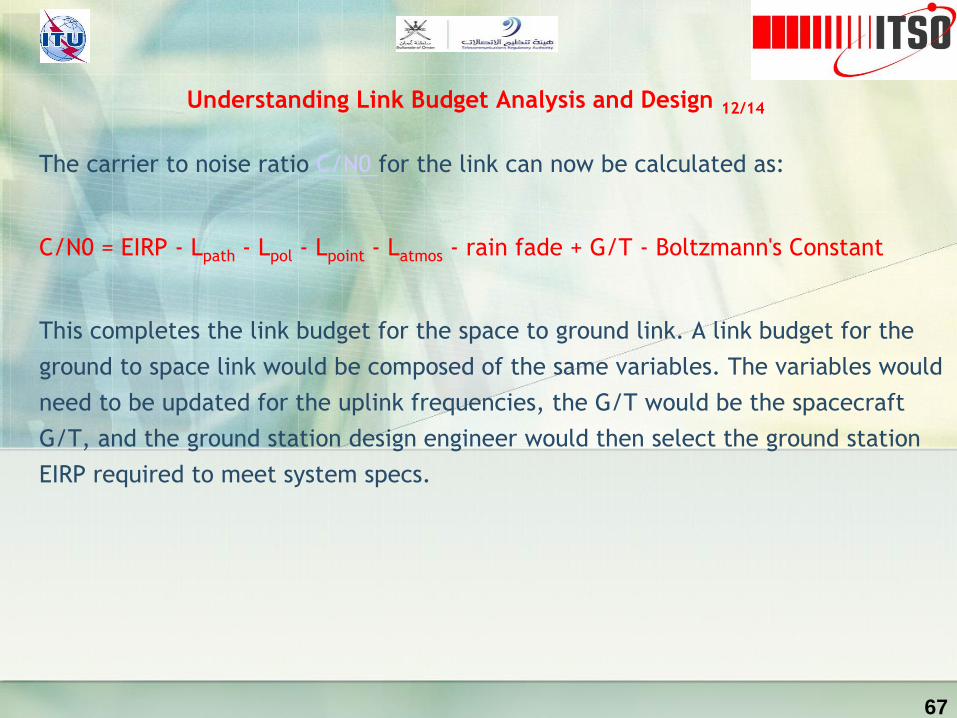
The carrier to noise ratio C/N0 for the link can now be calculated as:
C/N0 = EIRP - Lpath - Lpol - Lpoint - Latmos - rain fade + G/T - Boltzmann's Constant
This completes the link budget for the space to ground link. A link budget for the
ground to space link would be composed of the same variables. The variables would
need to be updated for the uplink frequencies, the G/T would be the spacecraft
G/T, and the ground station design engineer would then select the ground station
EIRP required to meet system specs.
67
Understanding Link Budget Analysis and Design 12/14

Boltzmann's Constant (k) Amount of noise power contributed by 1 degree of
temperature, kelvin.
k = 1.38 * 10^(-23) Watt-second/K
or
-228.6 dBw/Hz
68
Understanding Link Budget Analysis and Design 13/14
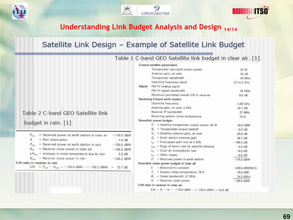
69
Understanding Link Budget Analysis and Design 14/14

End
Thank You!
Final Questions?