

COMMSERVICES, C.A Laboratorio Especializado en Radiocomunicaciones Trunking

ITU Training on C&I for Americas
Electromagnetic Compatibility EMC
VICTOR VELLANO NETOFundación CPqD: 24-28 Jun, 2013
Resumen Summary
Introducción (Introduction)Normalización internacional (International Standards)Conceptos básicos (Basic Concepts)Ensayos de CEM (EMC tests)Conceptos y cuidados con las cámaras anecoica y blindada (Concepts and care with anechoic and shielded chambers) Aspectos de acreditación (Accreditation aspects)Conclusión (Conclusion)
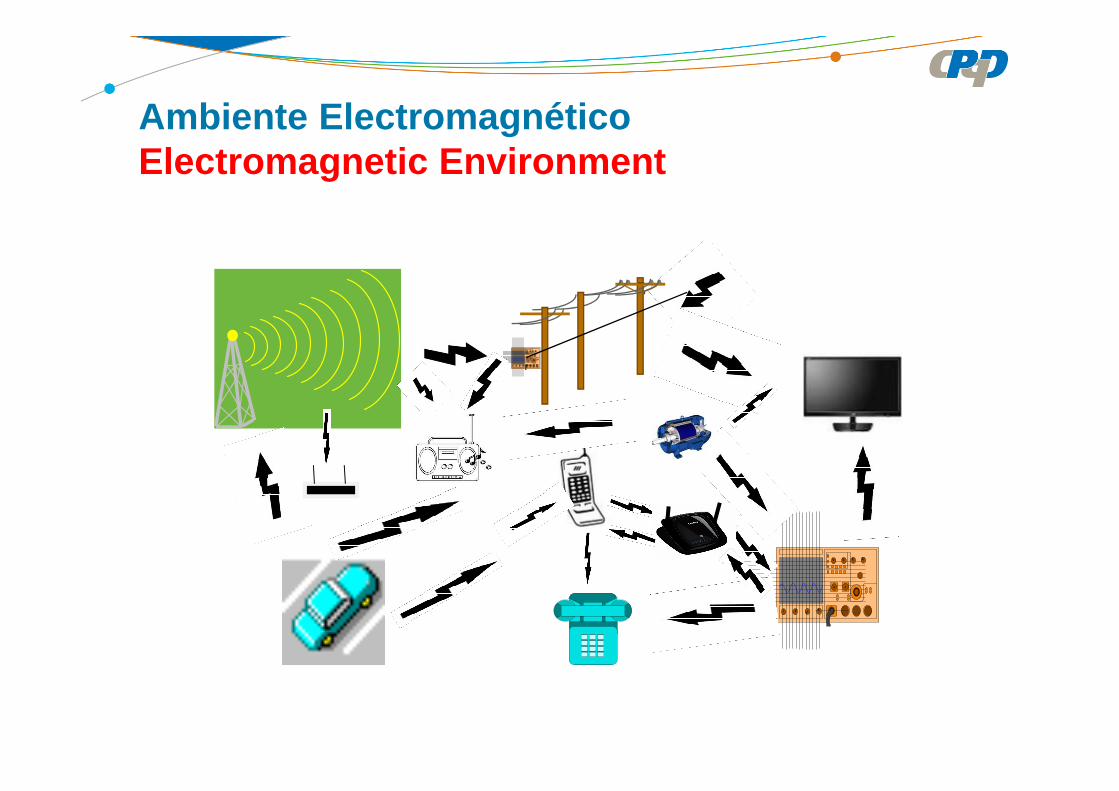
Ambiente ElectromagnéticoElectromagnetic Environment

Introducción – Introduction
Objetivo de la normalización de CEM(EMC standard objective)
• Garantizar la protección de los servicios de telecomunicaciones y radiodifusión (protección del espectro radioeléctrico)(Guarantee the protection of radiofrequency spectrum)
• Garantizar el funcionamiento adecuado del equipo en su ambiente electromagnético de operación(Guarantee the normal operation of equipment at the installation site)

Introducción – Introduction
Terminología – Terminology
Compatibilidad electromagnética (CEM) – capacidad de undispositivo, equipo o sistema de funcionar satisfactoriamente en suambiente electromagnético sin producir perturbación electromagnéticaintolerable para otras materias, equipos o sistemas contenidos en esteambiente
Electromagnetic compatibility – ability of an equipment or system tofunction satisfactorily in its electromagnetic environment withoutintroducing intolerable electromagnetic disturbances to anything in thatenvironment
IEV161-01-07
International Electrotechnical Vocabulary – Chapter 161: Electromagnetic compatibility

Introducción – Introduction
Terminología – Terminology
Interferencia electromagnética (IEM) – es la degradación deldesempeño de un equipo, canal de transmisión o de un sistemacausada por una perturbación electromagnética
Electromagnetic interference (EMI) – degradation of the performanceof an equipment, transmission channel system caused by anelectromagnetic disturbance
IEV161-01-06
International Electrotechnical Vocabulary – Chapter 161: Electromagnetic compatibility
Introducción – Introduction
Terminología – Terminology
Perturbación electromagnética – es un fenómeno electromagnéticocapaz de degradar el desempeño de un dispositivo, equipo o sistema ypuede ser un ruido electromagnético, una señal indeseable o unamodificación del medio de transmisión
Electromagnetic disturbance – any electromagnetic phenomenonwhich may degrade the performance of device, equipment or system,or adversely affect living or inert matter
IEV161-01-05
International Electrotechnical Vocabulary – Chapter 161: Electromagnetic compatibility

Introducción – Introduction
Terminología – Terminology
Inmunidad (a una perturbación) – capacidad de un dispositivo,equipo o sistema de no sufrir degradación de desempeño cuando en lapresencia de una perturbación electromagnética
Immunity (to a disturbance) – ability of a device, equipment orsystem to perform without degradation in the presence of anelectromagnetic disturbance
IEV161-01-20
International Electrotechnical Vocabulary – Chapter 161: Electromagnetic compatibility

Introducción – Introduction
Terminología – Terminology
Interferencia de radiofrecuencia – degradación de la recepción de una señal deseada causada por una perturbación de radiofrecuencia
Radio frequency interference – degradation of the reception of a wanted signal caused by radio frequency disturbance
IEV161-01-14
International Electrotechnical Vocabulary – Chapter 161: Electromagnetic compatibility

ISO – International Organization for Standardization
ITU – International Telecommunication Union
IEC – International Electrotechnical Commission
CISPR – Comité International Spécial des Perturbatio ns Radioélectriques
CENELEC – Comité Européen de Normalisation Electrotechnique
CIGRE – Conseil International Des Grands Réseaux Électriques
Introducción – Introduction

Normalización en Europa
CEN – Comité Europeo de Normalización
ETSI – European Telecommunication Standardization Institute
Introducción – Introduction
Normalización en Europa – Standardization in Europe
Las llamadas Directivas de nuevo enfoque establecen los requisitos esenciales que deben cumplir las mercancías para venderse en toda la UE
The EU legislation, referred to as new approach directives , sets the essential requirements that products have to meet to be sold across the EU
http://europa.eu/youreurope/business/profiting-from -eu-market/selling-goods/index_es.htm
Normalización en Europa – Standardization in Europe
Para ayudarlos se han publicado unas 20.000 normas europeas .Los productos que las cumplen se consideran conformes a lasdirectivas de la UE. Pero las normas no son obligatorias: losfabricantes pueden optar por otras soluciones técnicas para cumplir losrequisitos
To help them do so, some 20 000 European standards have beenpublished to date.Goods that comply with European standards are taken to comply withthe essential requirements laid down by EU directives. It is howevervoluntary and, if they prefer, manufacturers may choose other technicalsolutions to meet these requirements.
http://europa.eu/youreurope/business/profiting-from -eu-market/selling-goods/index_es.htm
Electrical Engineering Electromagnetic Compatibility (E MC)
Todos los aparatos eléctricos o instalaciones pueden influir en losdemás cuando interconectado o cerca uno del otro.La Directiva primero limita las EMC emisiones electromagnéticas .La Directiva también regula la inmunidad de equipos.
All electric devices or installations can influence each other wheninterconnected or close to each other.The EMC Directive first limits electromagnetic emissions of equipment.The Directive also governs the immunity of such equipment.
http://ec.europa.eu/enterprise/sectors/electrical/e mc/index_en.htm
Electromagnetic Compatibility (EMC) – Directive 2004 /108/EC
Directive 2004/108/EC relating to electromagnetic compatibility and repealing Directive 89/336/EECOJ L 390 of 31 December 2004
Directive repealed:Council Directive 89/336/EEC of 3 May 1989 on the approximation of the laws of the Member States relating to Electromagnetic CompatibilityOJ L 139 of 23 May 1989
http://ec.europa.eu/enterprise/policies/european-st andards/harmonised-standards/electromagnetic-compat ibility/index_en.htm
Articulo 3Los Estados miembros adoptarán todas las medidas adecuadas para garantizar que sólo se comercialicen y/o pongan en servicio los equipos que cumplan los requisitos de la presente Directiva cuando estén instalados, mantenidos y utilizados correctamente para los fines previstos.
Article 3Member States shall take all appropriate measures to ensure thatequipment is placed on the market and/or put into service only if itcomplies with the requirements of this Directive when properly installed,maintained and used for its intended purposes.
Directiva 2004/108/CE – EMC

Directiva 2004/108/CE – EMC
Artículo 42. Los requisitos de la presente Directiva no impedirán la aplicación en cualquier Estado miembro de las siguientes medidas especiales, relativas a la puesta en servicio o uso deEquipos:(a) medidas para superar un problema existente o previsto de compatibilidad
electromagnética en un lugar específico;(b) medidas adoptadas por motivos de seguridad para proteger las redes públicas de
telecomunicaciones o las estaciones receptoras o transmisoras cuando se utilicencon fines de seguridad en situaciones de espectro bien definidas.
Article 42. The requirements of this Directive shall not prevent the application in any MemberState of the following special measures concerning the putting into service or use ofequipment:(a) measures to overcome an existing or predicted electromagnetic compatibility problem
at a specific site;(b) measures taken for safety reasons to protect public telecommunications networks or
receiving or transmitting stations when used for safety purposes in well-definedspectrum situations.

Artículo 62. El cumplimiento por parte de los equipos de las normas armonizadas pertinentes,cuyas referencias se hayan publicado en el Diario Oficial de la Unión Europea, creará lapresunción, por parte de los Estados miembros, de conformidad con los requisitosesenciales mencionados en el Anexo I a los que dichas normas hagan referencia. Estapresunción de conformidad se limitará al ámbito de las normas armonizadas aplicadas ya los requisitos esenciales pertinentes cubiertos por tales normas armonizadas.
Article 62. The compliance of equipment with the relevant harmonised standards whosereferences have been published in the Official Journal of the European Union shall raisea presumption, on the part of the Member States, of conformity with the essentialrequirements referred to in Annex I to which such standards relate. This presumption ofconformity is limited to the scope of the harmonized standard(s) applied and the relevantessential requirements covered by such harmonized standard(s).
Directiva 2004/108/CE – EMC

ORG Reference Superseded Date of cessation
Cenelec EN55022:2010CISPR 22:2008 modified (ITE –emission)
EN 55022:2006and Amend
1.12.2013
Cenelec EN 55024:2010CISPR 24:2010(ITE – immunity)
EN55024:1998 and Amend
1.12.2013
http://ec.europa.eu/enterprise/policies/european-st andards/harmonised-standards/electromagnetic-compat ibility/index_en.htm
Normas Armonizadas – Directiva 2004/108/ECHarmonized Standards – Directive 2004/108/EC
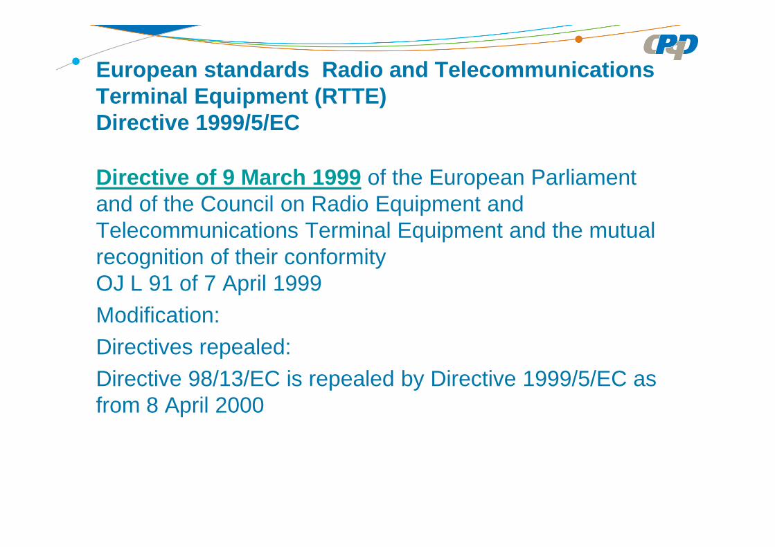
European standards Radio and Telecommunications Terminal Equipment (RTTE)Directive 1999/5/EC
Directive of 9 March 1999 of the European Parliament and of the Council on Radio Equipment and Telecommunications Terminal Equipment and the mutual recognition of their conformityOJ L 91 of 7 April 1999Modification:Directives repealed:Directive 98/13/EC is repealed by Directive 1999/5/EC as from 8 April 2000

Artículo 3. Requisitos esenciales1. Se aplicaran a todos los aparatos los requisitos esencialessiguientes:a) la protección de la salud y la seguridad del usuario o de cualquierotra persona, incluidos los objetivos respecto de los requisitos enmateria de seguridad que figuran en la Directiva 73/23/CEE, salvo enlo relativo al limite de tensión;b) los requisitos de protección que figuran en la Directiva 89/336/CEE,respecto de la compatibilidad electromagnética.
2. Los equipos radioeléctricos se construirán de forma que utilicen deforma eficaz el espectro asignado a las radiocomunicacionesterrenas/espaciales y los recursos orbitales para impedir lasinterferencias perjudiciales.
Directive 1999/5/EC – RTTE

Article 3. Essential requirements1. The following essential requirements are applicable to all apparatus:(a) the protection of the health and the safety of the user and any otherperson, including the objectives with respect to safety requirementscontained in Directive 73/23/EEC, but with no voltage limit applying;(b) the protection requirements with respect to electromagneticcompatibility contained in Directive 89/336/EEC.
2. In addition, radio equipment shall be so constructed that it effectivelyuses the spectrum allocated to terrestrial/space radio communicationand orbital resources so as to avoid harmful interference.
Directive 1999/5/EC – RTTE
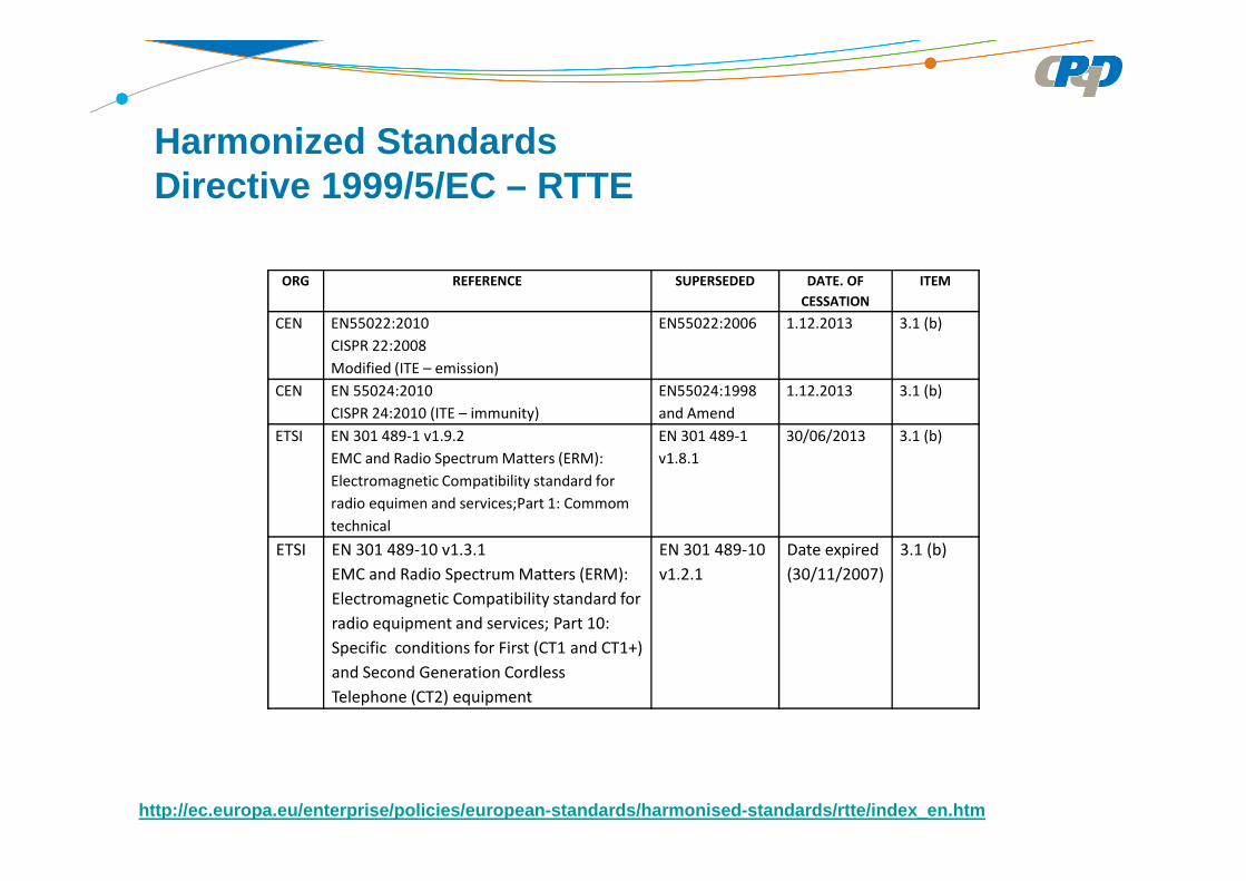
Harmonized Standards Directive 1999/5/EC – RTTE
http://ec.europa.eu/enterprise/policies/european-st andards/harmonised-standards/rtte/index_en.htm
ORG REFERENCE SUPERSEDED DATE. OF
CESSATION
ITEM
CEN EN55022:2010
CISPR 22:2008
Modified (ITE – emission)
EN55022:2006 1.12.2013 3.1 (b)
CEN EN 55024:2010
CISPR 24:2010 (ITE – immunity)
EN55024:1998
and Amend
1.12.2013 3.1 (b)
ETSI EN 301 489-1 v1.9.2
EMC and Radio Spectrum Matters (ERM):
Electromagnetic Compatibility standard for
radio equimen and services;Part 1: Commom
technical
EN 301 489-1
v1.8.1
30/06/2013 3.1 (b)
ETSI EN 301 489-10 v1.3.1
EMC and Radio Spectrum Matters (ERM):
Electromagnetic Compatibility standard for
radio equipment and services; Part 10:
Specific conditions for First (CT1 and CT1+)
and Second Generation Cordless
Telephone (CT2) equipment
EN 301 489-10
v1.2.1
Date expired
(30/11/2007)
3.1 (b)

http://ec.europa.eu/enterprise/policies/european-st andards/harmonised-standards/rtte/index_en.htm
ETSI EN 300 386 – Electromagnetic compatibility and Radio Spectrum Matters(ERM);Telecommunication Network Equipment; Electromagnetic Compatibility(EMC) requirements
• Condiciones de ensayo• Evaluación de calidad de funcionamiento• Aplicabilidad de los requisitos de emisión y inmunidad• Aspectos específicos relativos a los métodos de ensayo• Utiliza como referencia normas de la CEI y CISPR
• Test conditions• Performance analysis• Applicability of emission and immunity requirements• Particular aspects related to Test method for each piece of equipment• Use of IEC and CISPR standards as reference
Harmonized Standards Directive 1999/5/EC – RTTE
Organismos Internacionales relacionados con CEM International Organisms related to EMC
• International Telecommunication Union –Standards (ITU)
• International Electrotechnical Commission (IEC)
• Comité International Spécial des Perturbations Radioelectriquès (CISPR)

Some ITU-T Recommendations related to EMC
• ITU-T K38: Radiated emission test procedure for physically largesystems
• ITU-T K42: Preparation of emission and immunity requirements fortelecommunication equipment – General principles
• ITU-T K43: Immunity requirements for telecommunication equipment• ITU-T K48: Product family EMC requirements for each
telecommunication network equipment• ITU-T K49: Test condition and performance criteria for voice terminal
subject to interference from digital mobile phone• ITU-T K60: Emission levels and test methods for wireline
telecommunication networks to minimize electromagneticdisturbance of radio services
http://www.itu.int/ITU-T/recommendations/index_sg.a spx?sg=5
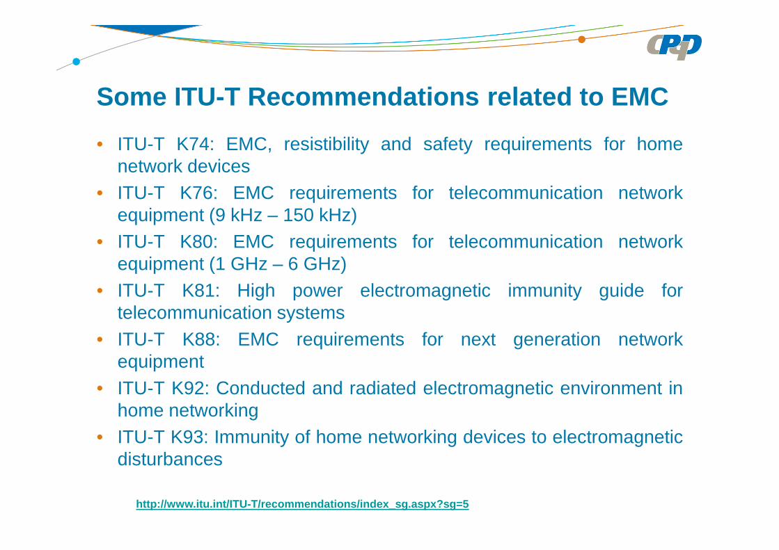
Some ITU-T Recommendations related to EMC
• ITU-T K74: EMC, resistibility and safety requirements for homenetwork devices
• ITU-T K76: EMC requirements for telecommunication networkequipment (9 kHz – 150 kHz)
• ITU-T K80: EMC requirements for telecommunication networkequipment (1 GHz – 6 GHz)
• ITU-T K81: High power electromagnetic immunity guide fortelecommunication systems
• ITU-T K88: EMC requirements for next generation networkequipment
• ITU-T K92: Conducted and radiated electromagnetic environment inhome networking
• ITU-T K93: Immunity of home networking devices to electromagneticdisturbances
http://www.itu.int/ITU-T/recommendations/index_sg.a spx?sg=5

UIT-T K48 / ITU-T K48
UIT-T K48 – Requisitos de compatibilidad electromagnética de la familia de productos para cada equipo de la red de telecomunicacionesITU-T K48 – Product family EMC requirements for each telecommunication network equipment
Esta Recomendación especifica los requisitos de emisión e inmunidad deequipos de conmutación, transmisión, potencia, estación radio base detelefonía móvil digital, LAN inalámbrica, sistema de transmisión digital de radio,línea de abonado digital (xDSL) y los equipos de supervisión. También sedescriben las condiciones operativas para la emisión y las pruebas deinmunidad. También se especifican los criterios de funcionamiento de losensayos de inmunidad.This Recommendation specifies the emission and immunity requirements forswitching, transmission, power, digital mobile base station, wireless LAN, digitalradio relay system, digital subscriber line (xDSL) and supervisory equipment. Italso describes operational conditions for emission and immunity testing.Performance criteria for immunity tests are also specified.

UIT-T K48 – Requisitos de compatibilidad electromagnética de la familia de productos para cada equipo de la red de telecomunicacionesITU-T K48 – Product family EMC requirements for each telecommunication network equipmentRequisitos de emisión• Los métodos de prueba e sus limites están de acuerdo con CISPR 22. El limite
depende del local de instalación: centro de telecomunicaciones o en el exterior. • Los equipos de radiocomunicaciones excluyendo las estaciones de base móviles
digitales se clasifican como:• Categoría 1: equipos con antena integrada
• Categoría 1.1 equipos cuya frecuencia es inferior a 1 GHz• Categoría 1.2 equipos cuya frecuencia es superior a 1 GHz
• Categoría 2 equipos con antena no integrada• Para las categorías 1.2 y 2 se aplican CISPR 22. Considerar la banda de exclusión• Para las categorías 1.1 e estaciones de base móviles digitales se aplican la Rec.
UIT-R SM 329-10 limites de las emisiones en el dominio no esencial.
UIT-T K48 / ITU-T K48

Emission requirements• Test methods and their limits are in accordance with CISPR 22. The limit
depends on the place of installation: telecommunications center or outside.
• Radio communication equipment excluding digital mobile base stations are classified as:• Category 1 equipment with integrated antenna
• Category 1.1 equipment whose frequency is below 1 GHz• Category 1.2 equipment whose frequency is above 1 GHz
• Category 2 devices with integrated antenna• For categories 1.2 and 2 apply CISPR 22. Consider exclusion band• For categories 1.1 and digital mobile base stations apply
ITU-R SM 329-10 emissions limits in the spurious domain(ITU-R Recommendation SM.329-10 (2003), Unwanted emissions in the spurious domain. At present SM 329-12 – 2012)
UIT-T K48 / ITU-T K48
UIT-T K48 / ITU-T K48
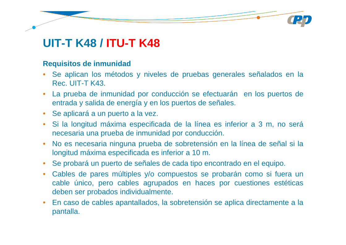
Requisitos de inmunidad• Se aplican los métodos y niveles de pruebas generales señalados en la
Rec. UIT-T K43.• La prueba de inmunidad por conducción se efectuarán en los puertos de
entrada y salida de energía y en los puertos de señales.• Se aplicará a un puerto a la vez.• Si la longitud máxima especificada de la línea es inferior a 3 m, no será
necesaria una prueba de inmunidad por conducción.• No es necesaria ninguna prueba de sobretensión en la línea de señal si la
longitud máxima especificada es inferior a 10 m.• Se probará un puerto de señales de cada tipo encontrado en el equipo.• Cables de pares múltiples y/o compuestos se probarán como si fuera un
cable único, pero cables agrupados en haces por cuestiones estéticasdeben ser probados individualmente.
• En caso de cables apantallados, la sobretensión se aplica directamente a lapantalla.

Requisitos de inmunidad• Apply the methods and general test levels specified in ITU-T K43.• The conductive immunity test shall be made in the input and output ports
power and signal ports.• Test shall be applied to one port at a time.• If the specified maximum length connected line is less than 3 m, it is not
necessary to test.• It is not required to test lines which the specified maximum length is less
than 10 m.• Shall be tested signal port of each type found in the equipment.• Multi-pair cables and / or compounds shall be tested as a single cable,
but wires grouped into bundles for aesthetic reasons must be tested individually.
• For the shielded cables, the voltage is applied directly to the screen.
UIT-T K48 / ITU-T K48
UIT-T K48 / ITU-T K48
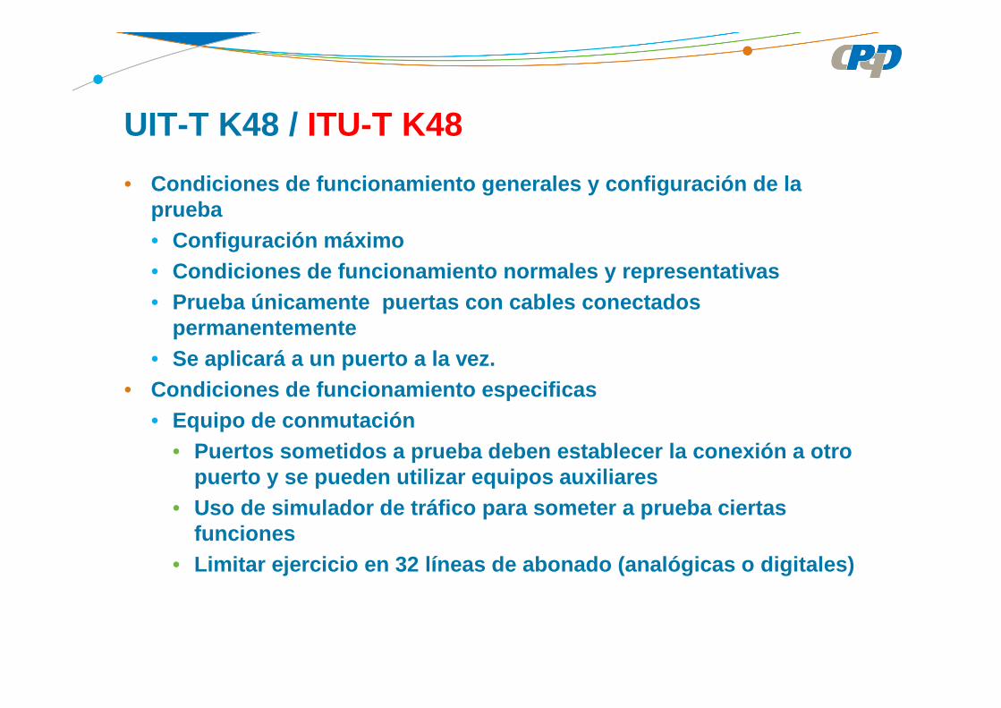
• Condiciones de funcionamiento generales y configura ción de la prueba• Configuración máximo• Condiciones de funcionamiento normales y representa tivas• Prueba únicamente puertas con cables conectados
permanentemente• Se aplicará a un puerto a la vez.
• Condiciones de funcionamiento especificas• Equipo de conmutación
• Puertos sometidos a prueba deben establecer la cone xión a otro puerto y se pueden utilizar equipos auxiliares
• Uso de simulador de tráfico para someter a prueba c iertas funciones
• Limitar ejercicio en 32 líneas de abonado (analógic as o digitales)

• Equipo de transmisión / Transmission Equipment
• Equipo de suministro de energía / Power Supply Equipment
• Equipo de supervisión / Supervisory Equipment.
• LAN inalámbricas / Wireless LAN
• Estación de base móvil digital (BS)/ Digital Mobile Base Station
• Sistemas de radioenlace digital / Digital Radio Relay System
• Equipos xDSL / xDSL equipment
UIT-T K48 / ITU-T K48

UIT-T K48 / ITU-T K48

UIT-T K48 / ITU-T K48
UIT-T K48 / ITU-T K48

UIT-T K48 / ITU-T K48
UIT-T K48 / ITU-T K48
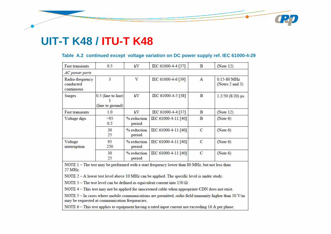
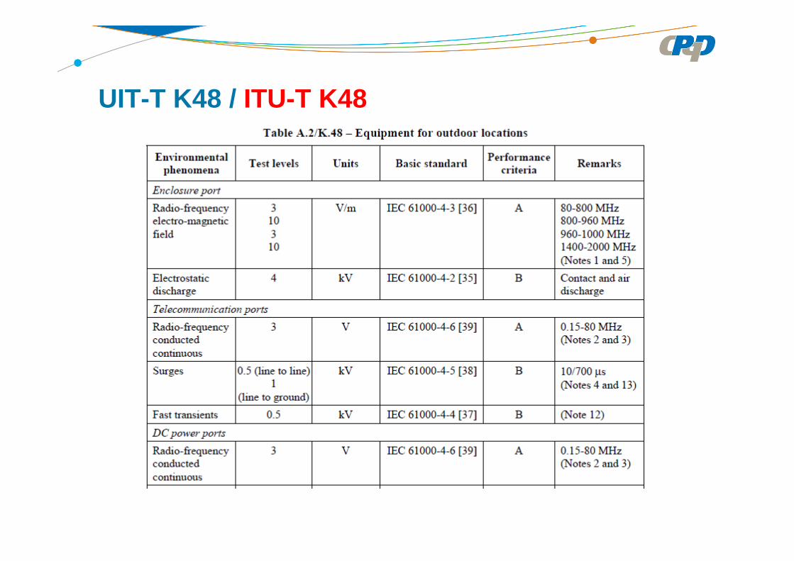
Table A.2 continued except voltage variation on DC power supply ref. IEC 61000-4-29
UIT-T K48 / ITU-T K48

UIT-T K48 / ITU-T K48

UIT-T K48 / ITU-T K48

Recomendaciones internacionales de CISPR utilizadas como referencias
• CISPR 22 – Information Technology Equipment – Radio DisturbanceCharacteristics – Limits and Methods of Measurement
• ITU-R SM.329-10 (2003) – Unwanted emissions in the spuriousdomain (emisiones no deseadas en el dominio no esencial)
• These publication establishes requirements in order to prevent radiointerference.
• Estas publicaciones establecen requisitos con el fin de evitarinterferencias de radio.

Recomendaciones internacionales básicas de la IEC sobre inmunidad electromagnéticaInternational IEC standards on electromagnetic immunity
• CISPR 24 – Características de inmunidad de ETIITE immunity characteristics
• IEC 61000-4-2 – Relativas a las descargas electrostáticasImmunity related to electrostatic discharge
• IEC 61000-4-3 – Relativas a radiaciones electromagnéticasImmunity related to RF electromagnetic fields
• IEC 61000-4-4 – Relativa a transitorios rápidos y salvas de impulsosImmunity related to EFT/B
• IEC 61000-4-5 – Relativa a ondas de choque (impulsos eléctricos)Immunity related to surges

Recomendaciones internacionales básicas de la IEC sobre inmunidad electromagnéticaInternational IEC standards on electromagnetic immunity
• IEC 61000-4-6 – Relativa a señales de radiofrecuencia conducidosImmunity related to conducted RF signals
• IEC 61000-4-11 – Relativa a interrupciones y variaciones de la tensión de alimentación de corriente alternada
Immunity related to variations and interruptions of the a.c. mains power
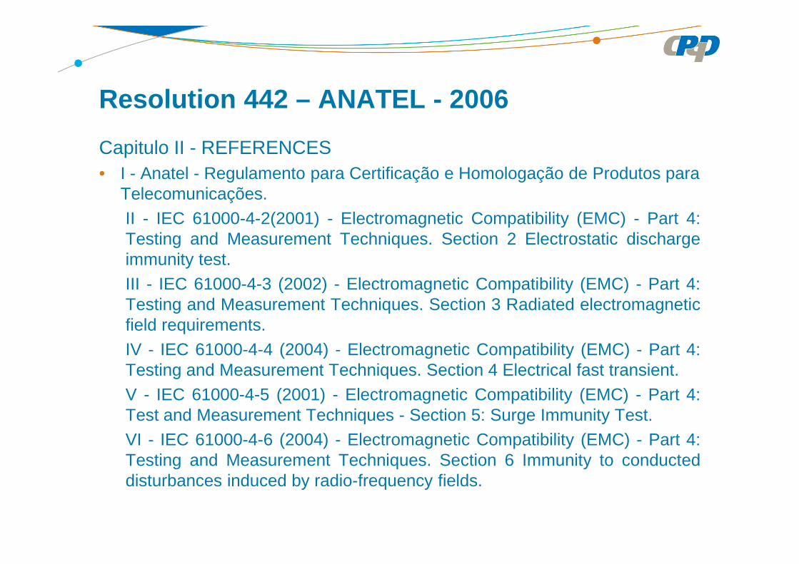
Capitulo II - REFERENCES• I - Anatel - Regulamento para Certificação e Homologação de Produtos para
Telecomunicações.II - IEC 61000-4-2(2001) - Electromagnetic Compatibility (EMC) - Part 4:Testing and Measurement Techniques. Section 2 Electrostatic dischargeimmunity test.III - IEC 61000-4-3 (2002) - Electromagnetic Compatibility (EMC) - Part 4:Testing and Measurement Techniques. Section 3 Radiated electromagneticfield requirements.IV - IEC 61000-4-4 (2004) - Electromagnetic Compatibility (EMC) - Part 4:Testing and Measurement Techniques. Section 4 Electrical fast transient.V - IEC 61000-4-5 (2001) - Electromagnetic Compatibility (EMC) - Part 4:Test and Measurement Techniques - Section 5: Surge Immunity Test.VI - IEC 61000-4-6 (2004) - Electromagnetic Compatibility (EMC) - Part 4:Testing and Measurement Techniques. Section 6 Immunity to conducteddisturbances induced by radio-frequency fields.
Resolution 442 – ANATEL - 2006
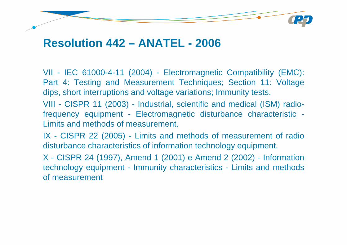
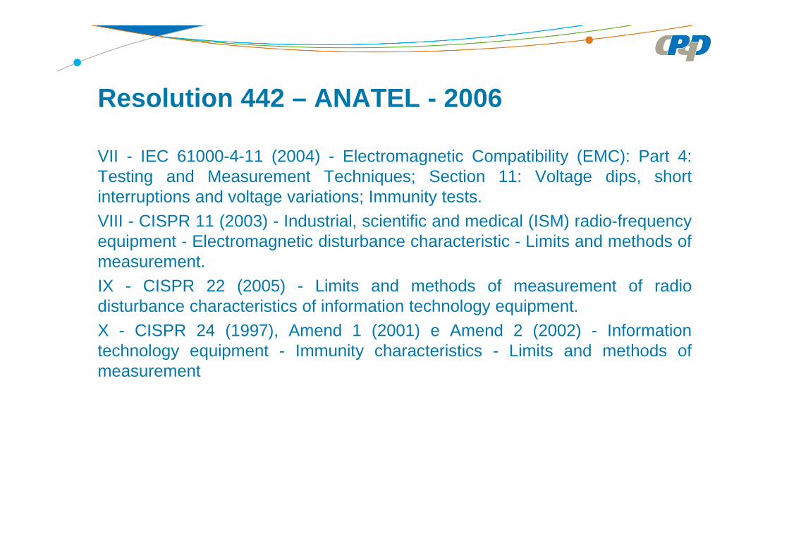
Resolution 442 – ANATEL - 2006
VII - IEC 61000-4-11 (2004) - Electromagnetic Compatibility (EMC):Part 4: Testing and Measurement Techniques; Section 11: Voltagedips, short interruptions and voltage variations; Immunity tests.VIII - CISPR 11 (2003) - Industrial, scientific and medical (ISM) radio-frequency equipment - Electromagnetic disturbance characteristic -Limits and methods of measurement.IX - CISPR 22 (2005) - Limits and methods of measurement of radiodisturbance characteristics of information technology equipment.X - CISPR 24 (1997), Amend 1 (2001) e Amend 2 (2002) - Informationtechnology equipment - Immunity characteristics - Limits and methodsof measurement
VII - IEC 61000-4-11 (2004) - Electromagnetic Compatibility (EMC): Part 4:Testing and Measurement Techniques; Section 11: Voltage dips, shortinterruptions and voltage variations; Immunity tests.VIII - CISPR 11 (2003) - Industrial, scientific and medical (ISM) radio-frequencyequipment - Electromagnetic disturbance characteristic - Limits and methods ofmeasurement.IX - CISPR 22 (2005) - Limits and methods of measurement of radiodisturbance characteristics of information technology equipment.X - CISPR 24 (1997), Amend 1 (2001) e Amend 2 (2002) - Informationtechnology equipment - Immunity characteristics - Limits and methods ofmeasurement
Resolution 442 – ANATEL - 2006

Capítulo III – Alcance Art. 3º : Las siguientes disposiciones se aplican a los equipos detelecomunicaciones. Los demás equipos que pueden desempeñarfunciones de telecomunicaciones u ofrecer accesos a servicios devalor añadido, incluso Internet, serán objeto de regulación específica.I - Los requisitos de emisión de perturbaciones electromagnéticas seaplican a los equipos sometidos a certificación obligatoria, tal como sedefine en las normas específicas contenidas en la sección I, del Art. 2En el caso de los equipos que utilizan el espectro radioeléctrico, losrequisitos de emisión perturbaciones electromagnéticas radiadasdescritas en el presente Reglamento se aplicará únicamente a laausencia de requisitos de emisiones intencional de radiofrecuencia oemisión de señales non esenciales dispuestos en reglamentaciónespecífica sobre el producto.
Resolución 442 – ANATEL - 2006
Resolución 442 – Anatel
Capítulo III – Alcance
II - Los requisitos de inmunidad a las perturbaciones electromagnéticas se aplican a los equipos clasificados como Productos de Telecomunicaciones de Categoría I y Categoría II, según definido en reglamentación específica mencionada en sección I de lo Art. 2, desde que destinado al uso previsto del público general (véase el anexo II).
III - El Requisitos de Resistibilidad a las perturbacioneselectromagnéticas se aplican a los productos de telecomunicacionesCategoría I y Categoría II, según definido en la reglamentaciónmencionada en la sección I del artículo. 2, desde que destinados al usopor el público en general (véase el anexo II).

Resolución 442 – Anatel
Productos de Telecomunicaciones de Categoría I : equipo terminal diseñado para su uso por el público en general para acceder al servicio de telecomunicaciones de interés colectivo.
Productos de Telecomunicaciones de Categoría II : equipos no incluidos en la definición de Categoría I, pero que hace el uso del espectro radioeléctrico, incluyendo antenas y los caracterizados en la regulación específica, como equipos de radiocomunicaciones de radiación Estricta;
Productos de Telecomunicaciones de Categoría III : cualquier producto o equipo, que no lo son, cubiertos por las categorías I y II, para lo cual es necesaria la regulación;

Conceptos Básicos Basic Concepts

A
AxX AdB µ
µµ 1
log20=
V
VxX VdB µ
µµ 1
log20=
mV
mVxX mVdB /1
/log20/ µ
µµ =
mW
mWxX dBm 1
log10=
Decibelio para expresar la medida de magnitudes uti lizadas en EMC
dBm ↔ 1 mW como referencia. 0 dBm = 1 mW
dBµA ↔ 1 µA como referencia. 0 dB µA = 1 µA
dBµV ↔ 1 µV como referencia. 0 dB µV = 1 µV
dB µV/m ↔ 1 µV/m como referencia
Conceptos Básicos / Basic Concepts

Detección de pico, valor medio e cuasi-pico
Conceptos Básicos / Basic Concepts
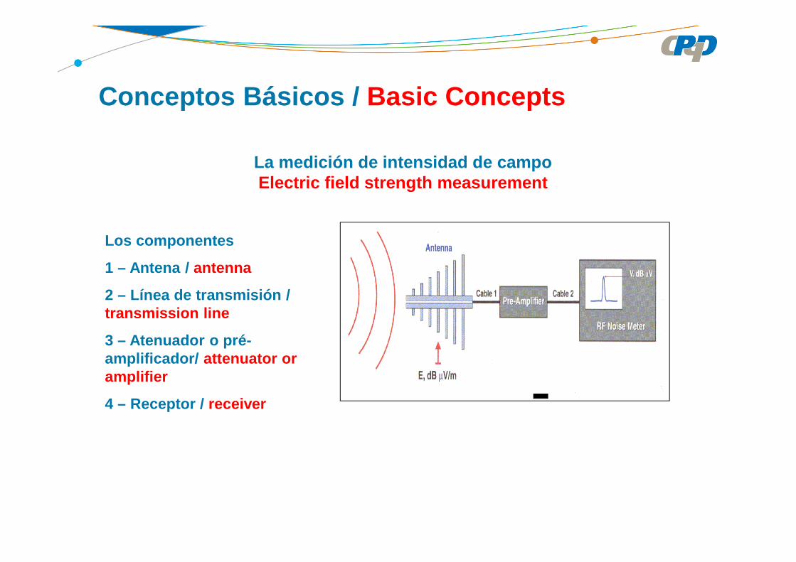
La medición de intensidad de campoElectric field strength measurement
Los componentes
1 – Antena / antenna
2 – Línea de transmisión / transmission line
3 – Atenuador o pré-amplificador/ attenuator or amplifier
4 – Receptor / receiver
Conceptos Básicos / Basic Concepts
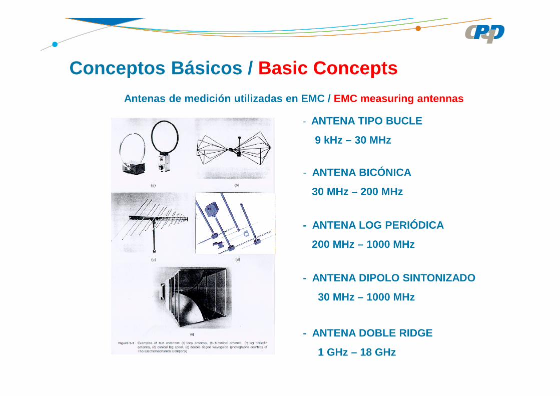
Antenas de medición utilizadas en EMC / EMC measuring antennas
- ANTENA TIPO BUCLE
9 kHz – 30 MHz
- ANTENA BICÓNICA
30 MHz – 200 MHz
- ANTENA LOG PERIÓDICA
200 MHz – 1000 MHz
- ANTENA DIPOLO SINTONIZADO
30 MHz – 1000 MHz
- ANTENA DOBLE RIDGE
1 GHz – 18 GHz
Conceptos Básicos / Basic Concepts
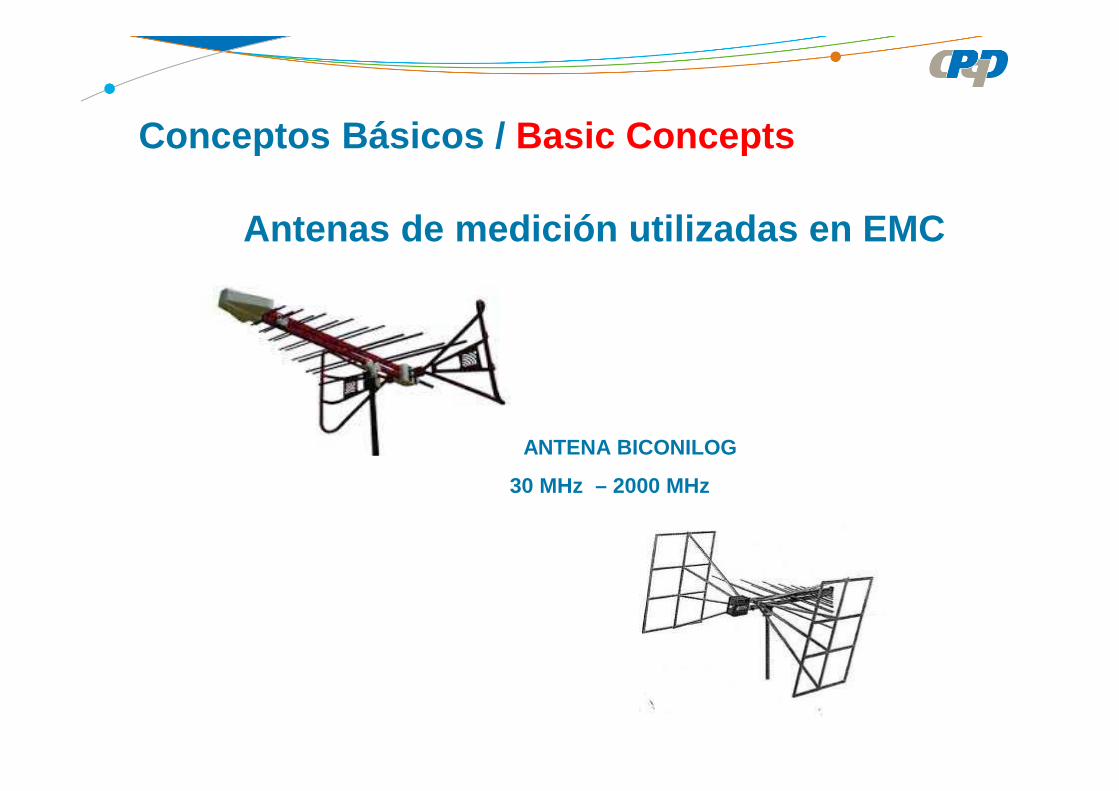
Antenas de medición utilizadas en EMC
- - ANTENA BICONILOG
30 MHz – 2000 MHz
Conceptos Básicos / Basic Concepts

FACTOR DE ANTENA AF
(“ANTENNA FACTOR - AF”)
Relación del campo eléctrico con la tensión en el terminal de la antena
(V)rec
(V/m)(1/m)
V
EAF =
E
Vrec
Conceptos Básicos / Basic Concepts

FACTOR DE ANTENA AF(“ANTENNA FACTOR - AF”)
En decibelios:
)][dB(mV)][dB(V/m)dB( 1AFVE −+= µµ
E
Vrec
V/m10E 20
E
V/m
V/mdB
µµ
µ =
Conceptos Básicos / Basic Concepts

iGλ
9,73AF =
Donde:
Gi = Ganancia de la antena con relación a antena de referencia isotrópica/ gain related to an isotropic antenna
λ = longitud de onda / wavelength = c/f
FACTOR DE ANTENA x GANANCIA DE LA ANTENA
ANTENNA FACTOR x ANTENNA GAIN
AFdB(1/m)= 20 log fMHz – 29,78 – GidB
Conceptos Básicos / Basic Concepts
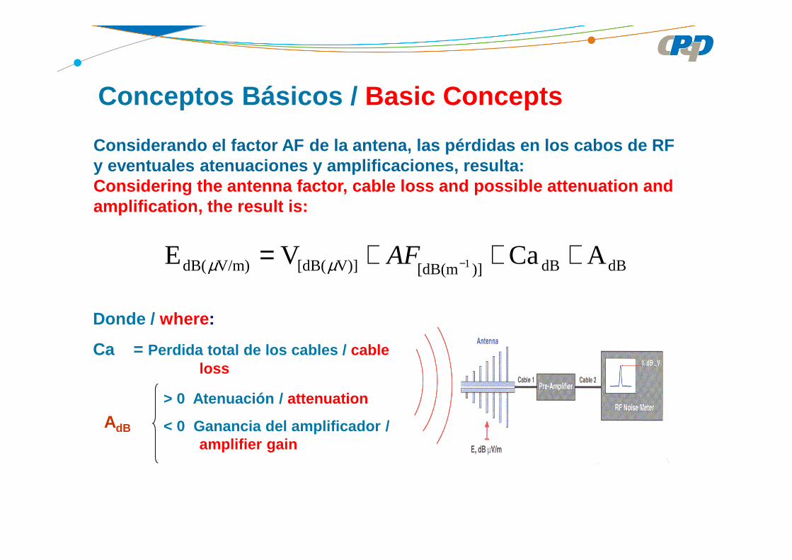
Donde / where :
Ca = Perdida total de los cables / cable loss
> 0 Atenuación / attenuation
< 0 Ganancia del amplificador / amplifier gain
Considerando el factor AF de la antena, las pérdida s en los cabos de RF y eventuales atenuaciones y amplificaciones, result a:Considering the antenna factor, cable loss and poss ible attenuation and amplification, the result is:
dBdB)][dB(mV)][dB(V/m)dB( ACaVE 1 +++= −AFµµ
AdB
Conceptos Básicos / Basic Concepts

ASPECTOS SOBRE LOS ENSAYOS DE CEMASPECTS REGARDING EMC TEST

Publication CISPR 22
• CISPR 22 (2008) – Information Technology Equipment – RadioDisturbance Characteristics – Limits and Methods ofMeasurement
• This publication establishes requirements for the radio disturbanceemission and methods of measurement in order to prevent radiointerference.
• Esta publicación establece requisitos para la emisión deperturbaciones radioeléctricas y de los métodos de medición con elfin de evitar interferencias de radio.
Publication CISPR 22
Information Technology Equipment (ITE)any equipment: which has a primary function of (or a combination of) entry, s torage, display,
retrieval, transmission, processing, switching, or contr ol, of data and oftelecommunication messages and which may be equipped with o ne or moreterminal ports typically operated for information transfe r;
It includes, for example, data processing equipment , office machines, electronic business equipment and telecommunication equipment.
Equipos de tecnología de información (ITE)cualquiera equipo que tiene una función primaria de (o una combinación de) entrada, almacenamiento,
visualización, recuperación, transmisión, transformación, distribución, o el control delos datos y mensaje de telecomunicaciones que puede estar equipado con uno omás puertos terminales habilitados para la transmisión de la información;
Incluye, por ejemplo, equipos de procesamiento de datos, máquinas de oficina, equipo de presentación electrónica y equipos de telecomunicaciones.

Classification of ITE
Class B ITE is intended primarily for use in the domestic envir onment and may include:– includes equipment with no fixed place of use; por table equipment and telecommunication terminal, personal computers and auxiliary connected equipment.NOTE: The domestic environment is an environment whe re the use of broadcast radio and television receivers may be expected with in a distance of 10 m of the apparatus concerned.
Class A ITE is a category of all other ITE which satisfies the class A ITE limits but not the class B ITE limits. Such equipment should n ot be restricted in its sale but the following warning shall be included in the inst ructions for use.
WarningThis is a class A product. In a domestic environmen t this product may cause radio interference in which case the user may be required to take adequate measures.
Publication CISPR 22

Publication CISPR 22
Importante aspecto de la CISPR 22 a mencionar es el uso de los detectores de valor medio, pico y cuasi-pico / Important aspect of CISPR 22 to be mentioned is the use average peak and quas i-peak detectors
Emisión conducida – uso dos detectores de valor medi o e do cuasi-pico / conducted emission – use of average and quasi-peak detectors
En emisión radiada hasta 1 GHz – uso del detector de cuasi-pico / radiated emission up to 1 GHz – use of quasi-peak det ector
En emisión radiada superior a 1 GHz - ¨6 GHz – uso del detector de valor medio / radiated emission higher than 1 GHz – use of average and peak detectors

Publication CISPR 22
• Emisiones a partir de los terminales de energía eléctrica y de los terminales de telecomunicaciones
• Uso de detectores de valor medio y valor cuasi-pico / usage of average and quasi peak detectors
• Red fictícia (AMN – Artificial mains network)• Red estabilizada de impedancia (ISN – Impedance Stabilization Network)• Faja de frecuencia de 150 kHz a 30 MHz / frequency range of 150 kHz to
30 MHz• Perturbación ambiente 6 dB abajo del limite (uso de cámara blindada) /
Ambient disturbances 6 dB below the limit (usage of shielded chamber)
F
N
T
EAE

Limites de emisión a partir de las líneas de alimen tación
OBS.: Medición con red artificial tipo “ V ”
F
N
T
FRECUENCIA
MHzLIMITES en dB
CLASE B (µ (µ (µ (µV)
Cuasi-pico Valor medio
0,15 - 0,50 66 a 56 56 a 46
0,5 - 5 56 46
5 - 30 60 50
Según UIT-T K48 puede ser utilizada corriente equiva lenteAccording to ITU-T K48 can be used equivalent curre nt
EAE
Publication CISPR 22

Publication CISPR 22
Circuito según la CISPR / Circuit according CISPR
Red artificial / Artificial mains network – AMN
Line impedance stabilization network - LISN
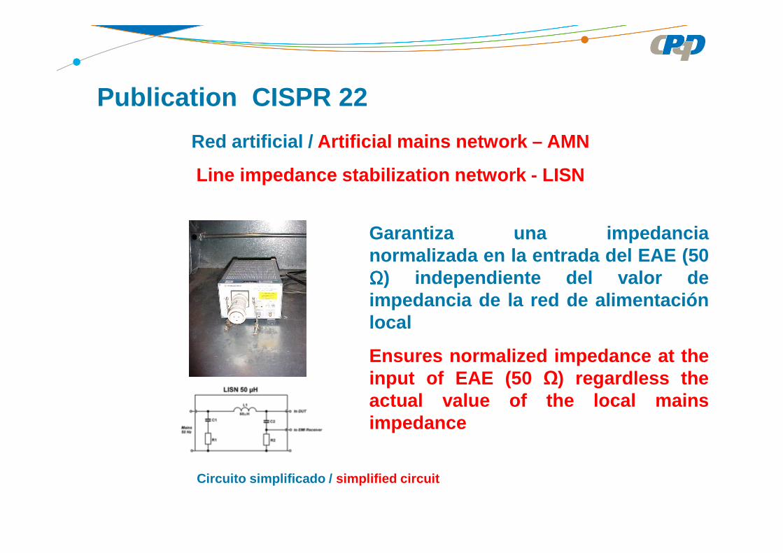
Red artificial / Artificial mains network – AMN
Line impedance stabilization network - LISN
Garantiza una impedancianormalizada en la entrada del EAE (50ΩΩΩΩ) independiente del valor deimpedancia de la red de alimentaciónlocal
Ensures normalized impedance at theinput of EAE (50 Ω) regardless theactual value of the local mainsimpedance
Publication CISPR 22
Circuito simplificado / simplified circuit

Reduce la presencia deperturbación del ambientesobre los niveles de emisiónque serán medidos
Reduce the presence ofdisturbance of theenvironment on the emissionlevels to be measured
Publication CISPR 22
Red artificial / Artificial mains network – AMN
Line impedance stabilization network - LISN

Publication CISPR 22
Ensayo de emisión conducida – línea de alimentación
• Ejemplo de montaje de ensayo / test setup
EAE/EUT
AMNEAE/EUT
AMN
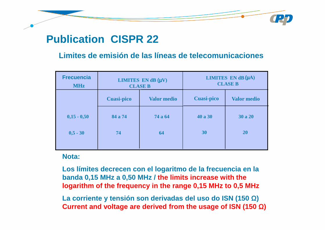
Nota:
Los límites decrecen con el logaritmo de la frecuen cia en la banda 0,15 MHz a 0,50 MHz / the limits increase with the logarithm of the frequency in the range 0,15 MHz to 0,5 MHz
La corriente y tensión son derivadas del uso do ISN (150 ΩΩΩΩ) Current and voltage are derived from the usage of I SN (150 ΩΩΩΩ)
Limites de emisión de las líneas de telecomunicacio nes
FREQUÊNCIAMHz
LIMITES EN dBCLASE B
(µ(µ(µ(µV)
Cuasi-pico Valor medio
0,15 - 0,50 84 a 74 74 a 64
0,5 - 30 74 64
Cuasi-pico Valor medio
LIMITES EN dBCLASE B
(µ(µ(µ(µA)
40 a 30 30 a 20
2030
Frecuencia
Publication CISPR 22
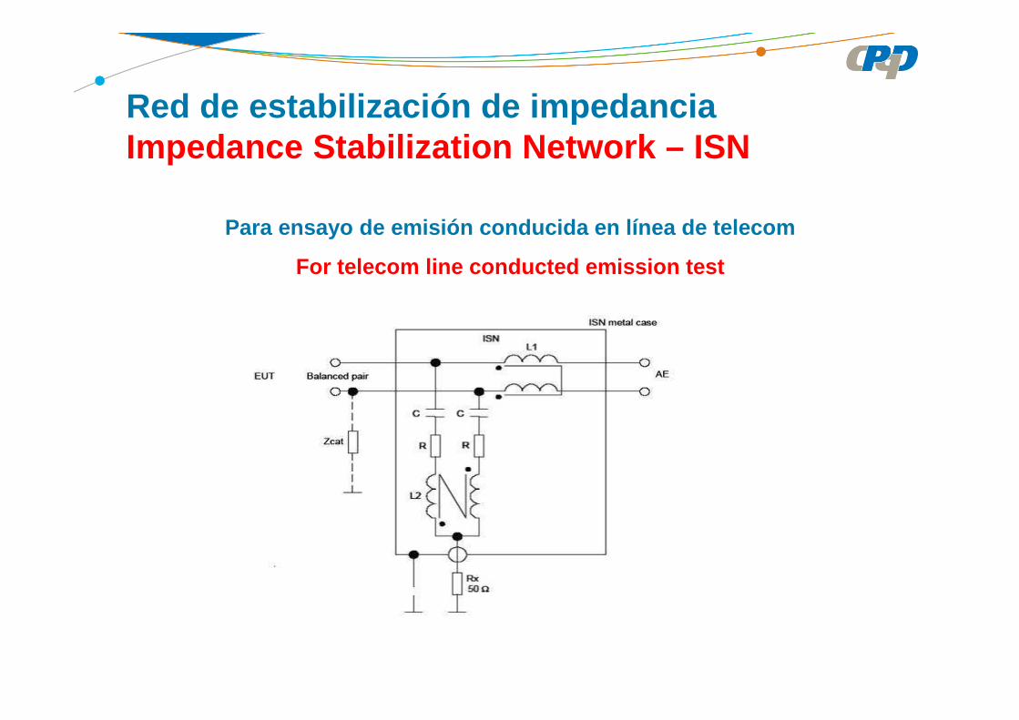
Red de estabilización de impedancia Impedance Stabilization Network – ISN
Para ensayo de emisión conducida en línea de teleco m
For telecom line conducted emission test
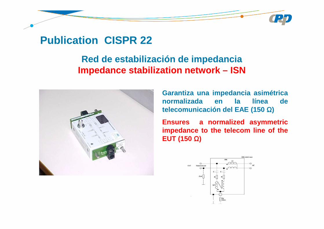
Garantiza una impedancia asimétricanormalizada en la línea detelecomunicación del EAE (150 ΩΩΩΩ)
Ensures a normalized asymmetricimpedance to the telecom line of theEUT (150 ΩΩΩΩ)
Publication CISPR 22
Red de estabilización de impedanciaImpedance stabilization network – ISN
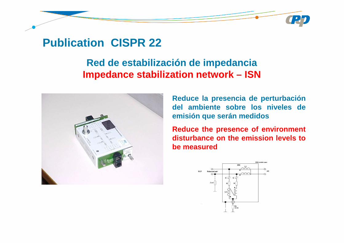
Reduce la presencia de perturbacióndel ambiente sobre los niveles deemisión que serán medidos
Reduce the presence of environmentdisturbance on the emission levels tobe measured
Red de estabilización de impedanciaImpedance stabilization network – ISN
Publication CISPR 22
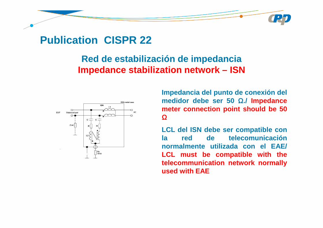
Impedancia del punto de conexión delmedidor debe ser 50 ΩΩΩΩ./ Impedancemeter connection point should be 50ΩΩΩΩ
LCL del ISN debe ser compatible conla red de telecomunicaciónnormalmente utilizada con el EAE/LCL must be compatible with thetelecommunication network normallyused with EAE
Publication CISPR 22
Red de estabilización de impedanciaImpedance stabilization network – ISN

Red de estabilización de impedanciaImpedance stabilization network – ISN
Publication CISPR 22
UC – tensión en modo común (fuerza electro-motriz) / common mode voltage
UD – tensión en modo diferencial / differential mode voltage
D
C
UU
20LOGLCL ====

Publication CISPR 22
Ejemplo de resultado de ensayo de emisión conducidaExample of conducted emission test result

Ejemplo de montaje de ensayo de emisión conducidaExample of conducted emission test setup
Publication CISPR 22
Equipo X
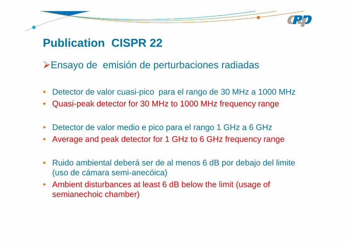
Ensayo de emisión de perturbaciones radiadas
• Detector de valor cuasi-pico para el rango de 30 MHz a 1000 MHz• Quasi-peak detector for 30 MHz to 1000 MHz frequency range
• Detector de valor medio e pico para el rango 1 GHz a 6 GHz• Average and peak detector for 1 GHz to 6 GHz frequency range
• Ruido ambiental deberá ser de al menos 6 dB por debajo del limite (uso de cámara semi-anecóica)
• Ambient disturbances at least 6 dB below the limit (usage of semianechoic chamber)
Publication CISPR 22

Publication CISPR 22
Para frecuencias superiores a 1 GHz, la decisión arespecto de la máxima frecuencia a ser medida esindicada en la tabla abajoFor frequencies above 1 GHz, the decision regardingthe maximum frequency to be measured is given in thetable below
Highest internal frequency (MHz)
Maximum frequency to measure (MHz)
< 108108 < fhighest < 500
f >1 000
100050006000
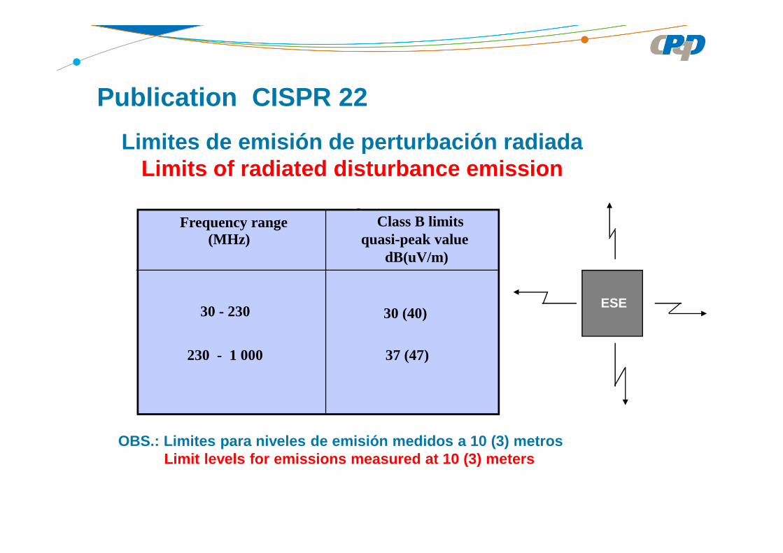
Limites de emisión de perturbación radiadaLimits of radiated disturbance emission
OBS.: Limites para niveles de emisión medidos a 10 (3) metrosLimit levels for emissions measured at 10 (3) meter s
dB (µµµµV/m)
CLASSE A CLASSE B
Frequency range(MHz)
30 - 230 30 (40)
230 - 1 000 37 (47)
Class B limitsquasi-peak value
dB(uV/m)
Publication CISPR 22
ESE
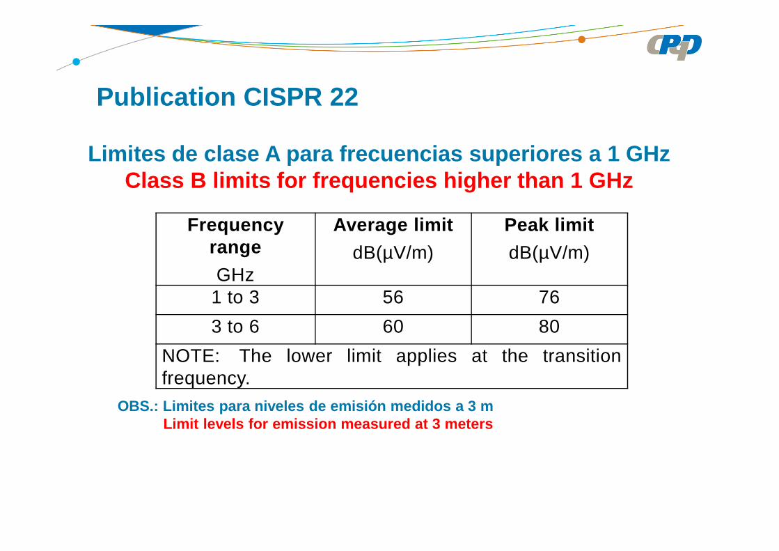
Limites de clase A para frecuencias superiores a 1 GHzClass B limits for frequencies higher than 1 GHz
OBS.: Limites para niveles de emisión medidos a 3 m Limit levels for emission measured at 3 meters
Frequency range
GHz
Average limit
dB(µV/m)
Peak limit
dB(µV/m)
1 to 3 56 76
3 to 6 60 80
NOTE: The lower limit applies at the transitionfrequency.
Publication CISPR 22

Frequency range
GHz
Average limit
dB(µV/m)
Peak limit
dB(µV/m)
1 to 3 50 70
3 to 6 54 74
NOTE The lower limit applies at the transitionfrequency.
Limites de clase B para frecuencias superiores a 1 GHzClass B limits for frequencies higher than 1 GHz
OBS.: Limites para niveles de emisión medidos a 3 m Limit levels for emission measured at 3 meters
Publication CISPR 22
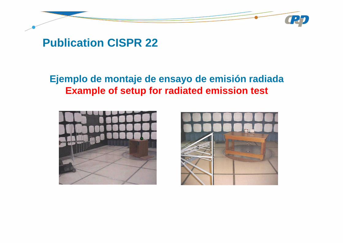
Publication CISPR 22
Ejemplo de montaje de ensayo de emisión radiada Example of setup for radiated emission test
Ensayo de inmunidad a perturbaciones electromagnéticas
Electromagnetic disturbances immunity test
Performance criteria (ITU-T K.43)
Criterion A – The equipment shall continue to operate asintended. No degradation of performance or loss of function isallowed below a performance level specified by themanufacturer, when the equipment is used as intended. In som ecases, the performance level may be replaced by a permissibl eloss of performance. If the minimum performance level or thepermissible performance loss is not specified by themanufacturer, then either of these may be derived from theproduct description and documentation and what the user mayreasonably expect from the equipment if used as intended.
(for continuous phenomenon)
Ensayos de inmunidad electromagnéticaElectromagnetic immunity tests
Performance criteria (ITU-T K.43)
Criterion B – After the test, the equipment shall continue to operate asintended. No degradation of performance is allowed after th eapplication of the phenomena below a performance level spec ified bythe manufacturer, when the equipment is used as intended. In somecases, the performance level may be replaced by a permissibl e loss ofperformance. During the test, degradation of performance o r loss offunction is, however, allowed. No change of actual operatin g state orstored data is allowed. If the minimum performance level or t hepermissible performance loss is not specified by the manufa cturer,then either of these may be derived from the product descript ion anddocumentation and what the user may reasonably expect from t heequipment if used as intended.
(for no continuous phenomenon)
Ensayos de inmunidad electromagnéticaElectromagnetic immunity tests

Performance criteria (ITU-T K.43)
Criterion C – Loss of function is allowed, providedthe function is automatically recoverable or can berestored by the operation of the controls by the userin accordance with the manufacturer's instructions.Functions and information protected by a batterybackup shall not be lost.
(for no continuous phenomenon)
Ensayos de inmunidad electromagnéticaElectromagnetic immunity tests

Ensayo de inmunidad a descargas electrostáticas (ES D) según la norma IEC 61000-4-2
Electrostatic Discharge (ESD) immunity test according t oIEC 61000-4-2
Severity levelTest level
Sev. Contact (kV) Air (kV)
2468
248
15
1234
Criterio de desempeño BPerformance criterion B
Ensayos de inmunidad electromagnéticaElectromagnetic immunity tests
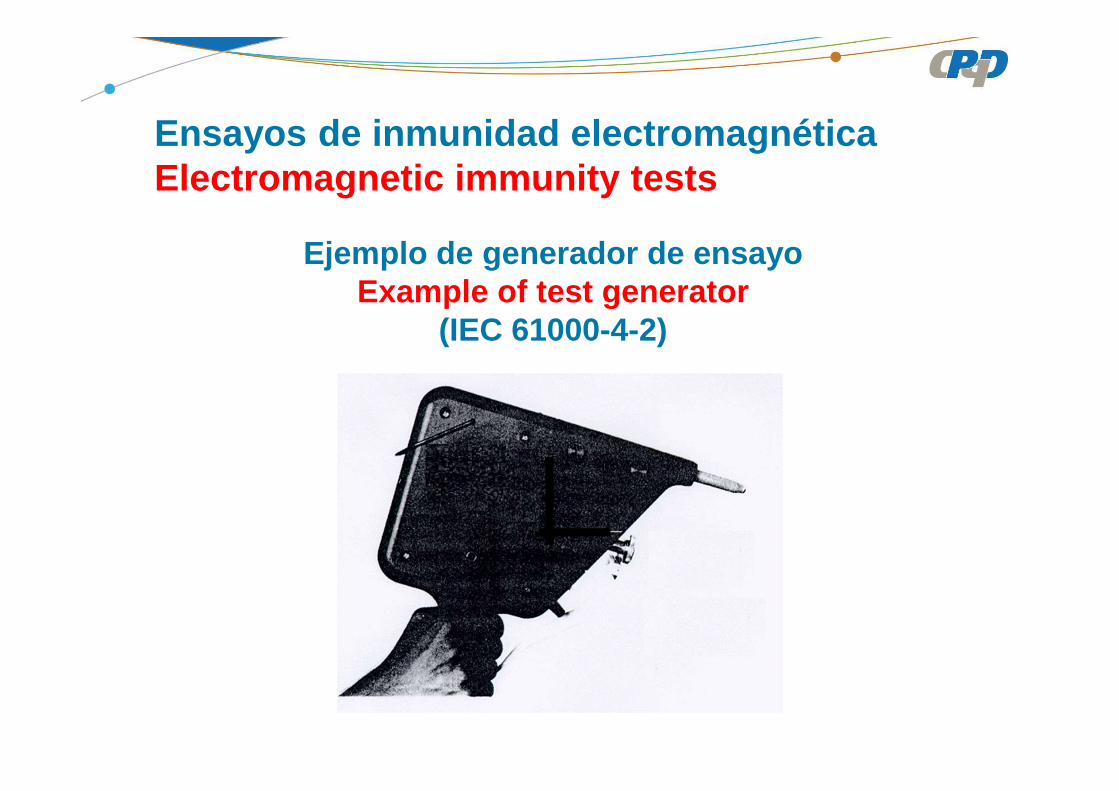
Ejemplo de generador de ensayoExample of test generator
(IEC 61000-4-2)
Ensayos de inmunidad electromagnéticaElectromagnetic immunity tests

plan vertical
plan horizontal
Ensayos de inmunidad electromagnéticaElectromagnetic immunity tests
Ejemplo del montaje de ensayoExample of Test setup
(IEC 61000-4-2)
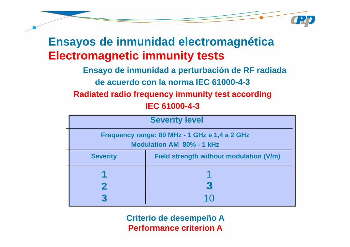
Frequency range: 80 MHz - 1 GHz e 1,4 a 2 GHzModulation AM 80% - 1 kHz
Severity level
Severity Field strength without modulation (V/m)
1 3
10
123
Ensayo de inmunidad a perturbación de RF radiadade acuerdo con la norma IEC 61000-4-3
Radiated radio frequency immunity test according IEC 61000-4-3
Ensayos de inmunidad electromagnéticaElectromagnetic immunity tests
Criterio de desempeño A Performance criterion A
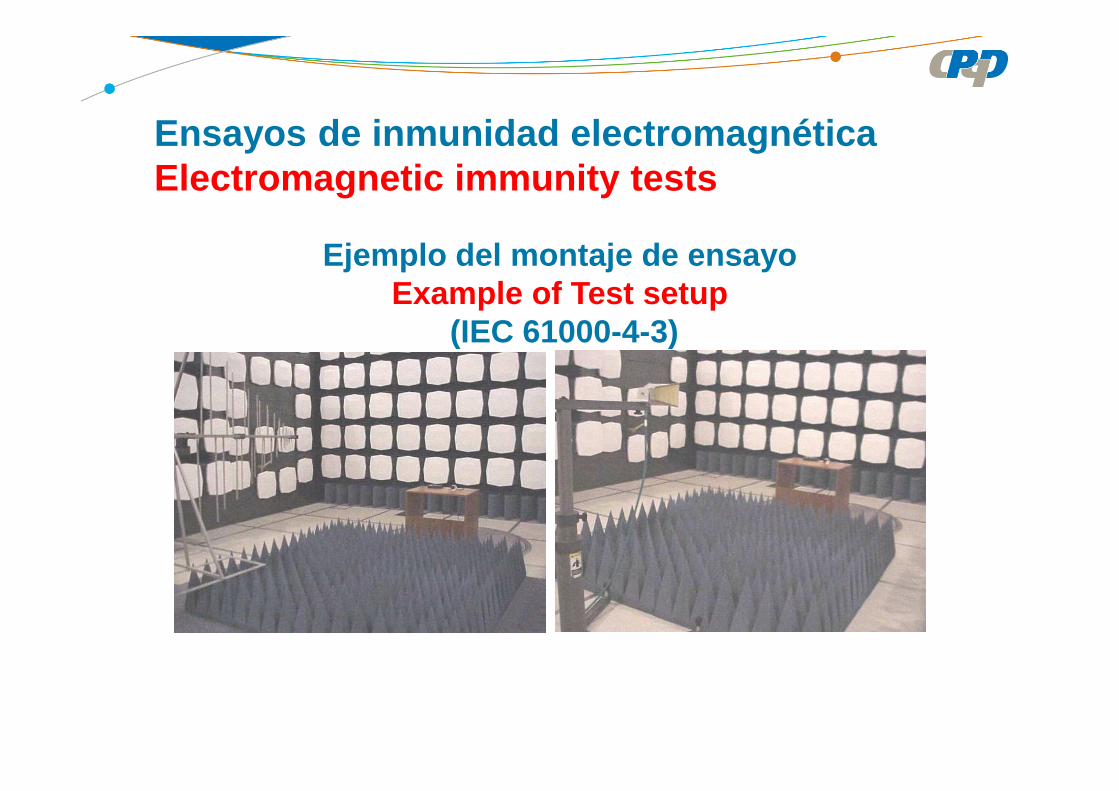
Ensayos de inmunidad electromagnéticaElectromagnetic immunity tests
Ejemplo del montaje de ensayoExample of Test setup
(IEC 61000-4-3)

Ensayos de inmunidad a transitorios eléctricos rápidos y salvas de impulsosElectrical fast transient and burst immunity test
IEC 61000-4-4
Severity level
tr/td: 5 ns/50 nsBURST: 15 ms/300 ms
Open circuit output voltage
0,51
24
0,250,5
12
Sev. Power supply lines (kV) Signal lines (kV)
1234
Criterio de desempeño B Performance criterion B
Ensayos de inmunidad electromagnéticaElectromagnetic immunity tests

Waveform according the IEC 61000-4-4
Ensayos de inmunidad electromagnéticaElectromagnetic immunity tests

Ensayos de inmunidad electromagnéticaElectromagnetic immunity tests
Ejemplo del montaje de ensayoExample of Test setup
(IEC 61000-4-4)

Ensayos de inmunidad electromagnéticaElectromagnetic immunity tests
Ejemplo del montaje de ensayoExample of Test setup
(IEC 61000-4-4)

Ensayo de inmunidad a las ondas de choque Surge immunity test
IEC61000-4-5• Algunas características del generador de ondas comb inadas / Some
combined wave generator characteristics• Tensión de salida en circuito abierto and corrient e de salida en corto
circuito son de acuerdo con especificaciones / output voltage with open circuit and output current with short circuit shall be according the specification
• Niveles de ensayo / test levels: 0.5; 1.0, 2.0, y 4 kV• Polaridad: positiva y negativa / polarity: positive and negative• Línea-línea (modo diferencial) y de línea para tier ra / line to line (differential
mode) and line to ground
• Criterio de desempeño B / performance criterion B
Ensayos de inmunidad electromagnéticaElectromagnetic immunity tests
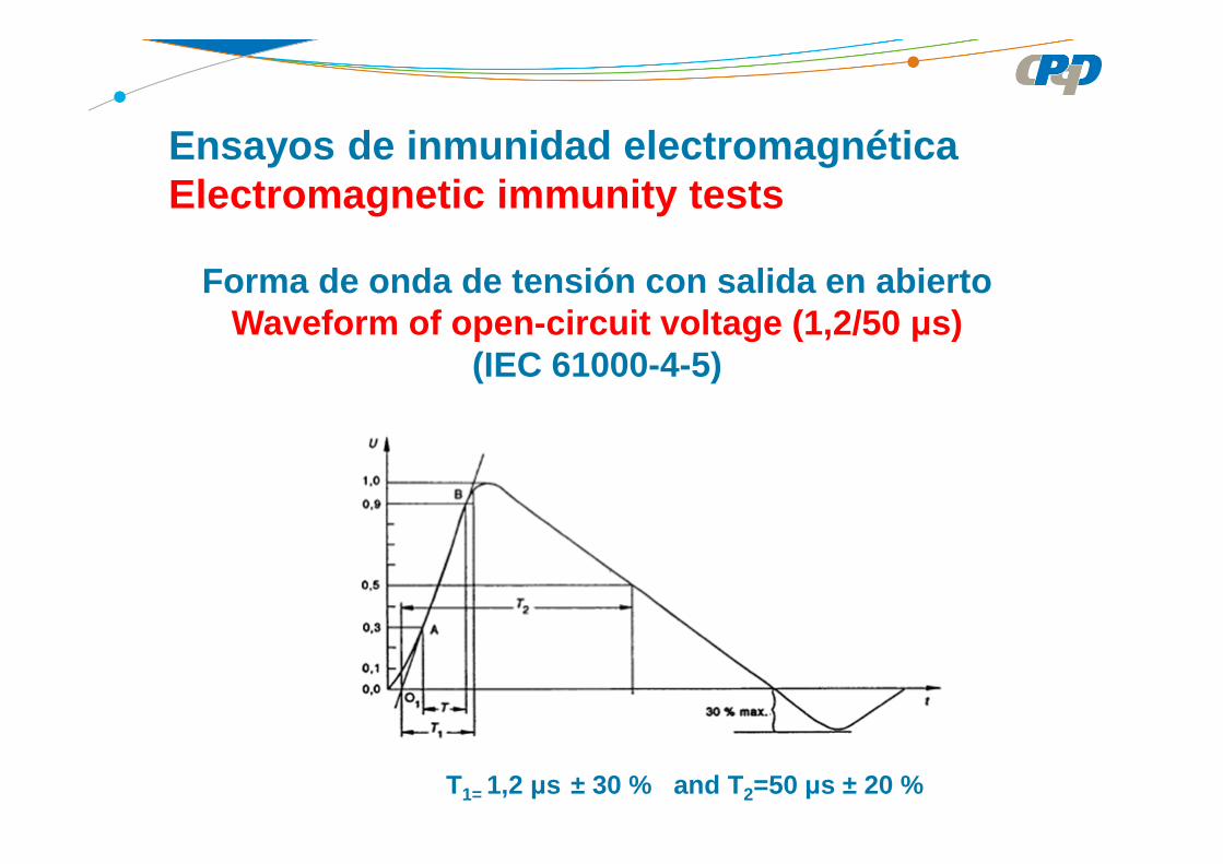
Forma de onda de tensión con salida en abiertoWaveform of open-circuit voltage (1,2/50 µs)
(IEC 61000-4-5)
Ensayos de inmunidad electromagnéticaElectromagnetic immunity tests
T1= 1,2 µs ± 30 % and T 2=50 µs ± 20 %

Forma de onda de corriente con salida en corto circ uitoWaveform of short-circuit current (8/20 µs)
(IEC 61000-4-5)
T1 = 8 µs ± 30 % and T 2= 20 µs ± 20 %
Ensayos de inmunidad electromagnéticaElectromagnetic immunity tests
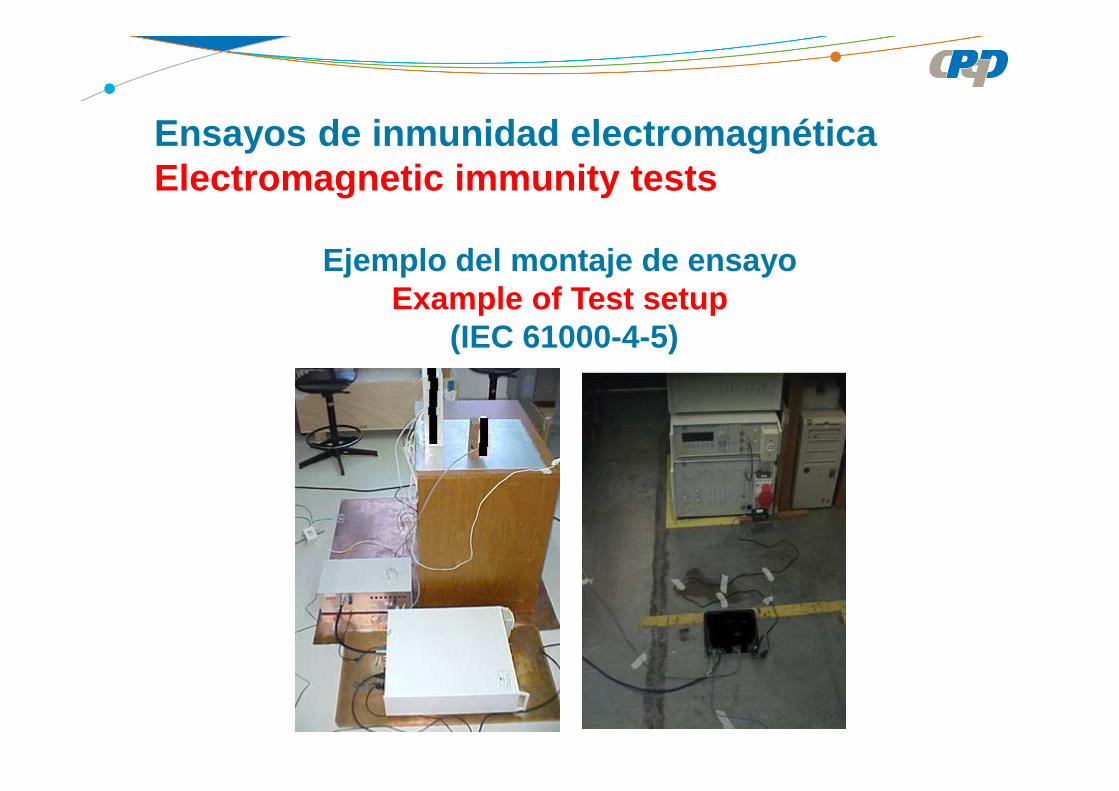
Ensayos de inmunidad electromagnéticaElectromagnetic immunity tests
Ejemplo del montaje de ensayoExample of Test setup
(IEC 61000-4-5)

Inmunidad a perturbaciones de RF conducidasImmunity to conducted RF disturbances
IEC 61000-4-6
Frequency range: 0.15 - 80 MHz
Test Levels
RMS Value without Modulation (V)
13
10
Criterio de desempeño A Performance criterion A
Ensayos de inmunidad electromagnéticaElectromagnetic immunity tests
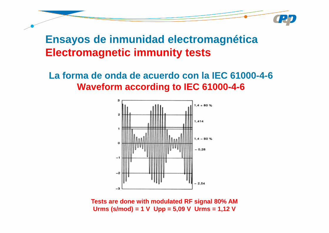
Tests are done with modulated RF signal 80% AMUrms (s/mod) = 1 V Upp = 5,09 V Urms = 1,12 V
Ensayos de inmunidad electromagnéticaElectromagnetic immunity tests
La forma de onda de acuerdo con la IEC 61000-4-6Waveform according to IEC 61000-4-6
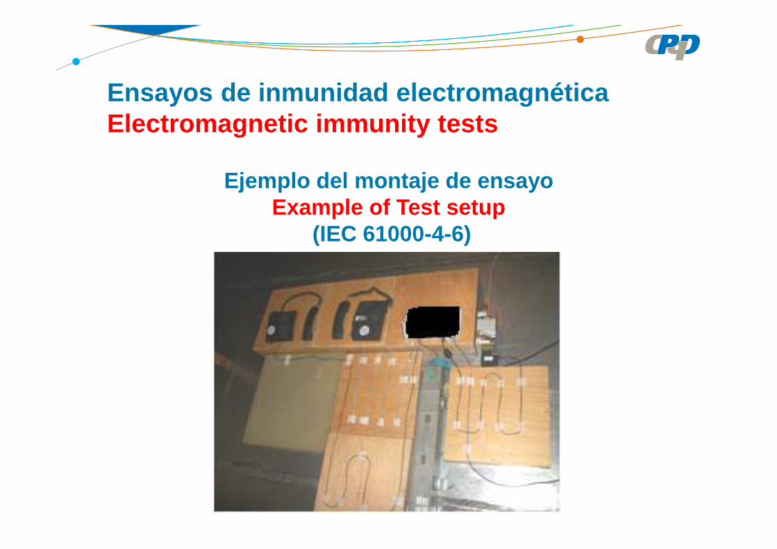
Ejemplo del montaje de ensayoExample of Test setup
(IEC 61000-4-6)
Ensayos de inmunidad electromagnéticaElectromagnetic immunity tests

Dispositivos de acoplamientoCoupling devices
Ensayos de inmunidad electromagnéticaElectromagnetic immunity tests

Inmunidad a reducciones y interrupciones de tensión c.a.Voltage dips, short interruptions and voltage varia tions immunity on a.c.
(IEC 61000-4-11)
Severity level Reduction Durationperiods/cicles
1 > 95 % 0,5
2 30 % 25
3 > 95 % 250
Limites de acuerdo con resolución 442 2 ANATELLimits according to Resolution 442 ANATEL
Critério B para nivel 1 y Critério C para los niveles 2 y 3
Ensayos de inmunidad electromagnéticaElectromagnetic immunity tests

Voltage dips, short interruptions and voltagevariations immunity tests
(IEC 61000-4-11)
Ensayos de inmunidad electromagnéticaElectromagnetic immunity tests

Ensayos de inmunidad electromagnéticaElectromagnetic immunity tests
Caídas de tensiónVoltage Dip
Interrupciones de tensión Voltage Interruption
Voltage dips, short interruptions and voltagevariations immunity tests
(IEC 61000-4-11)

Ejemplo del montaje de ensayoExample of Test setup
(IEC 61000-4-11)
Ensayos de inmunidad electromagnéticaElectromagnetic immunity tests
Uncertainty in Standardized EMC Tests
Incertidumbre en las pruebas normalizadas de EMC

Uncertainty in Standardized EMC Tests
MeasurandParticular quantity (magnitud) subject to measurementIEV 161-03-01
Uncertainty in Standardized EMC Tests
Measurement Instrumentation Uncertainty – MIUIncertidumbre de Instrumentación Medida - MIUparameter, associated with the result of a measurementthat characterizes the dispersion of the values that canreasonably be attributed to the measurand, induced by allrelevant influence quantities that are related to themeasurement instrumentation.
Measuring chain (cadena de medida)series of elements of a measuring instrument or systemthat constitutes the path of the measuring signal from inputto the output.

Uncertainty in Standardized EMC Tests
Standards Compliance Uncertainty – SCUIncertidumbre de conformidad de normas - SCUparameter, associated with the result of a compliance measurement as described in a standard, that characterizes the dispersion of the values that could reasonably be attributed to the measurand.
Tolerance (tolerancia)maximum variation of a value permitted by specifications, regulations, etc. for a given specified influence quantity (magnitud de influencia).

Uncertainty in Standardized EMC Tests
true value (of a quantity) valor verdadero (de una magnitud)value consistent with the definition of a particular quantity[adapted from ISO/IEC Guide 98-3, B.2.3, IEV 311-01-04].
uncertainty source (fuente de incertidumbre)source (descriptive, not quantitative) that contributes to theuncertainty of the value of a measurand, and that shall bedivided into one or more relevant influence quantities.

Uncertainty in Standardized EMC Tests
Emission TestUncertainty is related always to a quantity to be measured,so for conducted emission and radiated emissionrequirements the uncertainty is related to the quantifymeasured and the compliance status.
Immunity testsFor immunity the uncertainty is related to the disturbancesbe applicable to the test. Waveform and levels of thegenerated disturbance can have an uncertainty associatedto their characteristics and associated to how they appliedto the EUT.
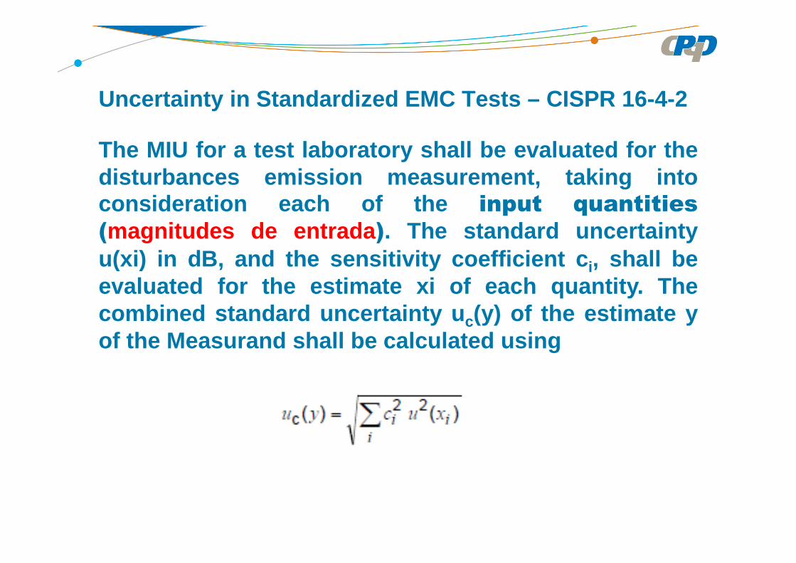
The MIU for a test laboratory shall be evaluated for thedisturbances emission measurement, taking intoconsideration each of the input quantities
(magnitudes de entrada ). The standard uncertaintyu(xi) in dB, and the sensitivity coefficient c i, shall beevaluated for the estimate xi of each quantity. Thecombined standard uncertainty u c(y) of the estimate yof the Measurand shall be calculated using
Uncertainty in Standardized EMC Tests – CISPR 16-4-2

If Ulab is less than or equal to Ucispr, then the test report mayeither state the value of Ulab or state that Ulab is less thanUcispr.If Ulab exceeds Ucispr, then the test report shall contain the valueof Ulab (in dB) for the measurement instrumentation actuallyused for the measurements.
NOTE: The equation above means that a coverage factor k = 2 isapplied that yields approximately a 95 % level ofconfidence for the near-normal distribution typical of mos tmeasurement results .
Uncertainty in Standardized EMC Tests – CISPR 16-4-2
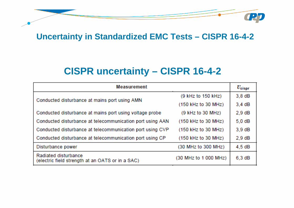
CISPR uncertainty – CISPR 16-4-2
Uncertainty in Standardized EMC Tests – CISPR 16-4-2

Input quantity / Magnitud de entrada
Xi
Uncertainty of Xi / Incertidumbre de x i
u(x i) c i c i u(x i)
dBDistribución de
probabilidaddB 1 dB
Receiver reading/Lectura del receptor ± 0,1 k =1 0,1 1 0,1
Attenuation AMN-receiver/Atenuación: AMN-receptor
± 0,1 k = 2 0,05 1 0,05
AMN voltage divison factor/Factor de divisiónde tensión de la AMN
± 0,2 k = 2 0,1 1 0,10
Sine wave voltage/tensión de ondasinusoidal
± 1,0 k = 2 0,5 1 0,5
Pulse amplitude response/respuesta de laamplitud de pulso
± 1,5 retangular 0,87 1 0,87
Pulse repetition rate response/respuesta a lafrecuencia de repetición de pulsos
± 1,5 retangular 0,87 1 0,87
Noies floor proximity/proximidad del ruído defondo
± 0,0 0,00 1 0,00
AMN frequency interolation/interpolation emfrecuencia del VDF de la AMN
±0,1 retangular 0,06 0,06
Mismatch AMN-receiver/esadaptación AMN-receptor
±0,07 formato U 0,53 1 0,05
AMN impedance/impedancia de la AMN +2,6/-2,7 triangular 1,08 1 1,08
Efeito of mains disturbance/efecto de lasperturbaciones de la red de alimentación
0,0 0,0
Effect of the environment / efecto del entorno 0,0 0,0
Conducted disturbance measurement from 150 kHz a 30 MHz using a 50 ΩΩΩΩ / 50 µH AMN
Mediciones de perturbaciones conducidas de 150 kHz a 30 MHz utilizando una AMN de 50 ΩΩΩΩ / 50 µH
Hence, expanded uncertainty uc(V) = 1,72 dB u E(V) = 3,44 dB
Uncertainty in Standardized EMC Tests – CISPR 16-4-2
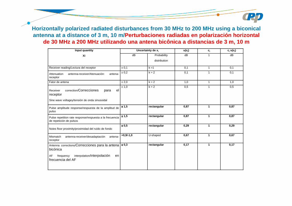
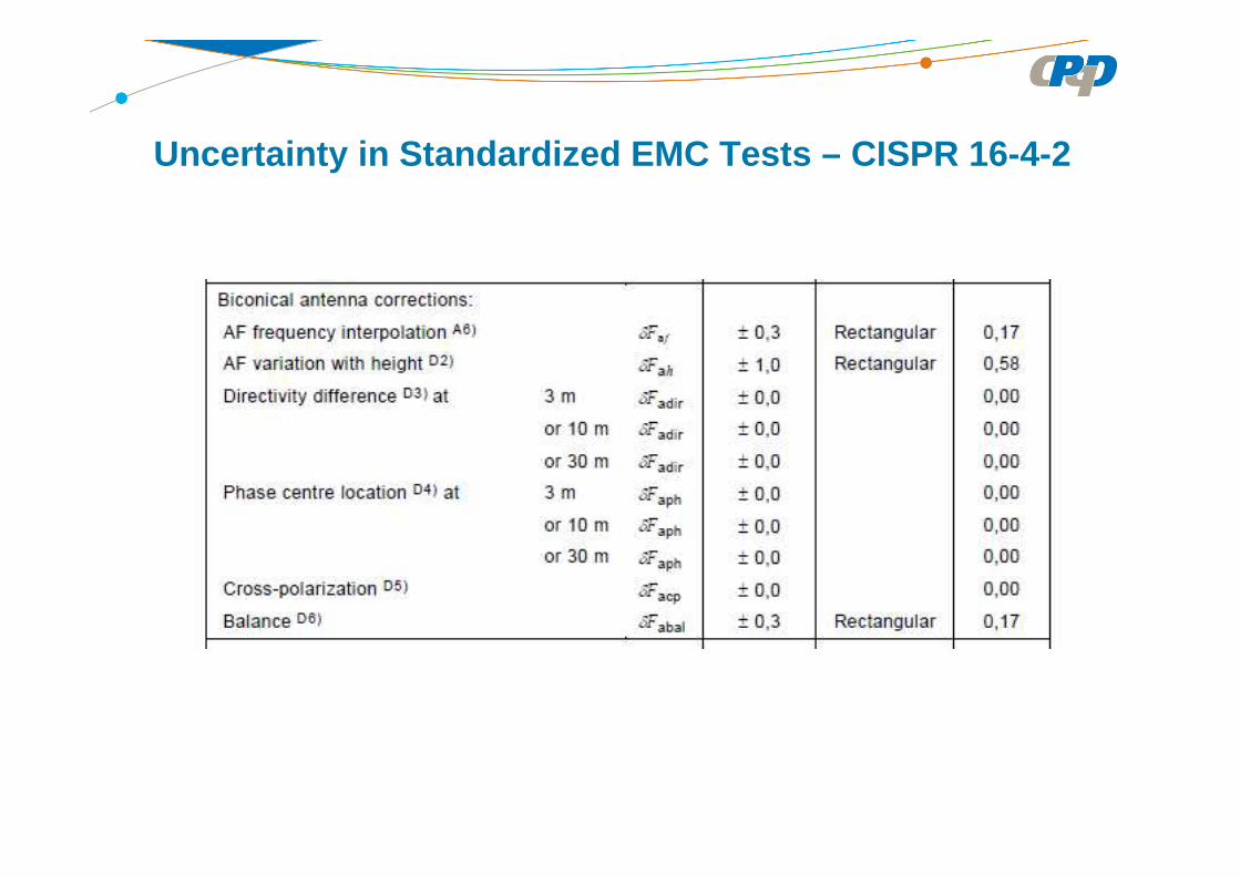
Horizontally polarized radiated disturbances from 3 0 MHz to 200 MHz using a biconicalantenna at a distance of 3 m, 10 m/ Perturbaciones radiadas en polarización horizontal
de 30 MHz a 200 MHz utilizando una antena bicônica a distancias de 3 m, 10 mInput quantity
Xi
Uncertainty de x i u(x i) c i c i u(x i)
dB Probability
distribution
dB 1 dB
Receiver reading/Lectura del receptor ± 0,1 k =1 0,1 1 0,1
Attenuation antenna-receiver/Atenuación: antena-receptor
± 0,2 k = 2 0,1 1 0,1
Fator de antena ± 2,0 k = 2 1,0 1 1,0
Receiver correction/Correcciones para elreceptor
Sine wave voltagey/tensión de onda sinusoidal
± 1,0 k = 2 0,5 1 0,5
Pulse amplitude response/respuesta de la amplitud depulso
±±±± 1,5 rectangular 0,87 1 0,87
Pulse repetition rate response/respuesta a la frecuenciade repetición de pulsos
±±±± 1,5 rectangular 0,87 1 0,87
Noies floor proximity/proximidad del ruído de fondo±±±± 0,5 rectangular 0,29 1 0,29
Mismatch antenna-receiver/desadaptación antena-receptor
+0,9/-1,0 U-shaped 0,67 1 0,67
Antenna corrections/Correcciones para la antenabicónica
AF frequency interpolation/Interpolación enfrecuencia del AF
±±±± 0,3 rectangular 0,17 1 0,17

AF variation with height/Variación del AFcon la altura
±±±± 1,0 rectangular 0,58 1 0,58
Directivity difference/ Diferencia endirectividad – d = 3 m
±±±± 0,0 0,0 1 0,0
Directivity difference/ Diferencia endirectividad – d = 10 m
±±±± 0,0 0,0 1 0,0
Directivity difference/ Diferencia endirectividad – d = 30 m
±±±± 0,0 0,0 1 0,0
Cross-polarization/Polarización cruzada ±±±± 0,0 0,0 1 0,0
Balance/balanceo ±±±± 0,3 rectangular 0,17 1 0,17Site imperfections/Imperfecciones delemplazamiento
±±±± 4,0 triangular 1,63 1 1,63
Separation distance/Distancia deseparación
d=3 m ±±±± 0,3 rectangular 0,17 1 0,17
Separation distance/Distancia deseparación
d=10m
±±±± 0,1 rectangular 0,06 1 0,06
Table height/Altura de la mesa d=3 m ±±±± 0,1 k = 2 0,05 1 0,05
Table heightAltura de la mesa d=10m
±±±± 0,1 k = 2 0,05 1 0,05
Horizontally polarized radiated disturbances from 3 0 MHz to 200 MHz using a biconicalantenna at a distance of 3 m, 10 m/ Perturbaciones radiadas en polarización horizontal
de 30 MHz a 200 MHz utilizando una antena bicônica a distancias de 3 m, 10 m
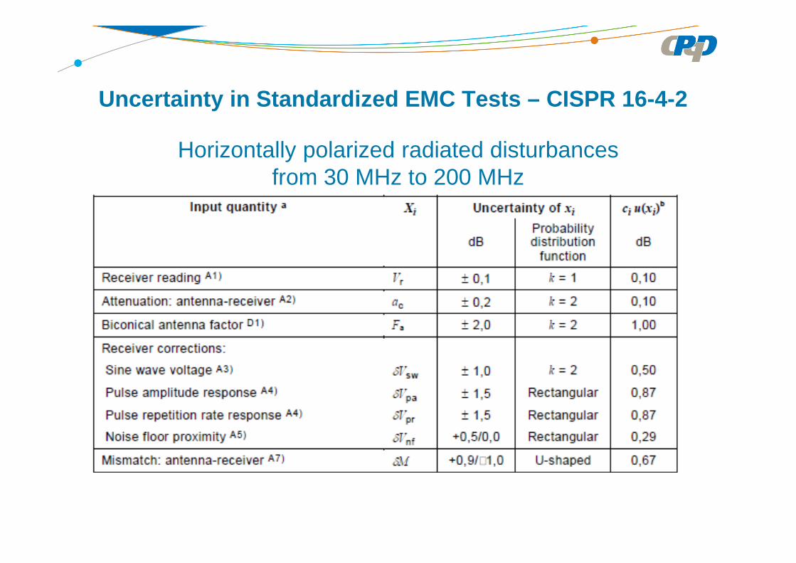
Horizontally polarized radiated disturbancesfrom 30 MHz to 200 MHz
Uncertainty in Standardized EMC Tests – CISPR 16-4-2
Uncertainty in Standardized EMC Tests – CISPR 16-4-2

Uncertainty in Standardized EMC Tests – CISPR 16-4-2
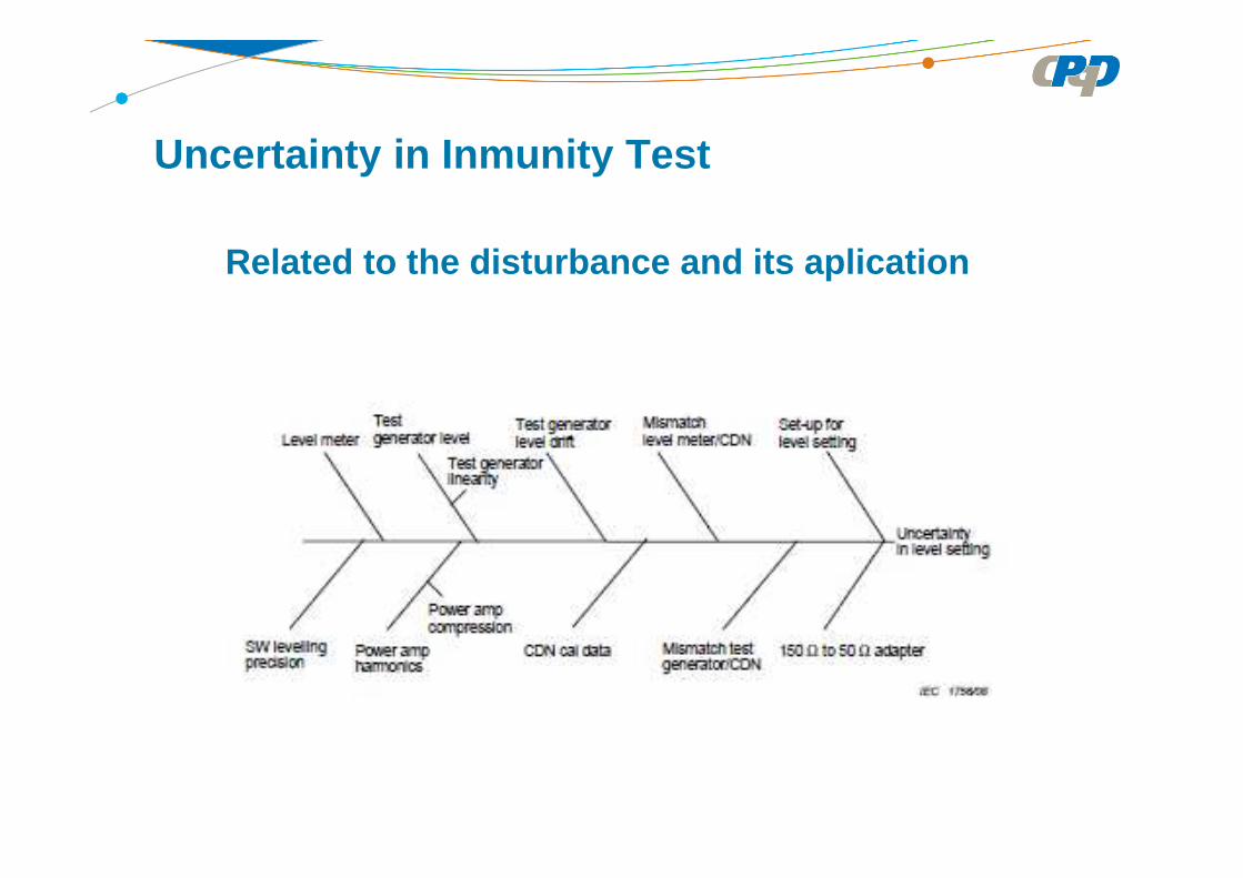
Uncertainty in Inmunity Test
Related to the disturbance and its aplication
AMBIENTE DE ENSAYO
TEST SITE
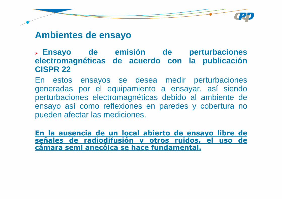
Ambientes de ensayo
Ensayo de emisión de perturbacioneselectromagnéticas de acuerdo con la publicaciónCISPR 22En estos ensayos se desea medir perturbacionesgeneradas por el equipamiento a ensayar, así siendoperturbaciones electromagnéticas debido al ambiente deensayo así como reflexiones en paredes y cobertura nopueden afectar las mediciones.
En la ausencia de un local abierto de ensayo libre deseñales de radiodifusión y otros ruidos, el uso decámara semi anecóica se hace fundamental.

Ambientes de ensayo
Ensayo de inmunidad a perturbacioneselectromagnéticas de acuerdo con la publicación IEC61000-4-3.En estos ensayos debe evitarse la emisión deperturbaciones electromagnéticas para el ambiente yequipos prójimos (emisión radiada/inducida y conducida).Además debe garantizarse la uniformidad de campoprescrita en la norma.
Para este ensayo es esencial el uso de la cámara semi
anecóica.

Ambientes de ensayo
Ensayo de inmunidad a perturbacioneselectromagnéticas conducidas de acuerdo con laspublicaciones IEC 61000-4-x .En estos ensayos debe evitarse o minimizarse la emisiónde perturbaciones electromagnéticas para el ambiente yotros equipos (emisión radiada/inducida y conducida).Normalmente en estos ensayos se tiene equipos auxiliarespara que ejerciten los EAE. O aún otros equipos enoperación en las proximidad.
Una cámara blindada es recomendada en estos casos(Excepto IEC 61000-4-3)

Local de medición de emisión radiada
OATS (OPEN AREA TEST SITE)LOCAL DE ENSAYO EN CAMPO ABIERTO (referencia)
LOCAL ALTERNATIVO DE ENSAYOCÁMARA SEMI ANECÓICA SEMI ANECHOIC CHAMBER

Local de medición de emisión radiada
Local de medición en campo abierto: el local de medicióndebe ser plano, libre de cables o estructuras que reflejenlos campos, suficientemente grande para permitir lacolocación de la antena de medición la una dada distanciadel EAE.

La atenuación del local de medición de emisión electromagnética radiada no debe diferir de más de ±4dB del valor teórico de la atenuación para un local ideal de medición.
Tanto el local abierto de medición como la cámara semianecóica deben atender al requisito de ±4dB de atenuación del local.
Local de medición de emisión radiada

Medición de “normalized site attenuation”
Configuraciones de las antenas para polarización horizontal
Vdirect = puntos 1 e 2 dos cables conectados diretamente

Medición de “normalized site attenuation”
Configuraciones de las antenas para polarización horizontal

RTsitedirectN AFAFVVA −−−=
AFT = factor de la antena transmisora
AFR = factor de la antena receptora
Vdirect = medida obtenida con los cabos conectados directa mente
Vsite = medida obtenida cuando los cabos del generador y receptor están conectados en la antena transmisora y antena receptora, respectivamente.
(Los cables y atenuadores no son considerados desde que utilizados tanto para medir Vdirect como Vsite )
Normalized site attenuationAtenuación del local normalizada
Medición de “normalized site attenuation”

Uniformidad del campo eléctrico
Ensayos de inmunidad electromagnética
La norma prescribe para el localde ensayo la necesidad deuniformidad de campo.
El campo es considerado uniformesi el nivel del mismo esté en labanda de 0 dB a +6 dB del valornominal, en por lo menos 75% dela superficie, o sea en 12 de los
16 puntos medidos.

Cámara semi anecóica
SOBRE EL MANTENIMIENTO
Limpieza de los contactos conductores de la puerta
Si hubo quiebra de los contactos, los mismos deben ser sustituidos
Limpieza de los contactos conductores de la mesa gi ratoria
Verificación de los materiales absorbentes de RF
Verificación continua del control de humedad y temp eratura

Limpieza de los contactos
Cámara semi anecóica
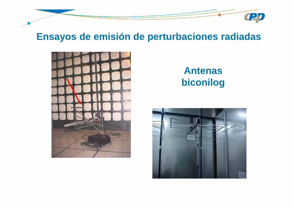
Antenas biconilog
Ensayos de emisión de perturbaciones radiadas

ISO IEC 1705 – GENERAL REQUIREMENTS FOR THE COMPETENCE OF TESTING AND CALIBRATION LABORATORIES

Contents1 Scope2 Normative references3 Terms and definitions4 Management requirements4.1 Organization4.2 Management system4.3 Document control4.4 Review of requests, tenders and contracts4.5 Subcontracting of tests and calibrations
ISO IEC 1705 (2005) – GENERAL REQUIREMENTS FOR THE COMPETENCE OF TESTING AND CALIBRATION LABORATORIES

4.6 Purchasing services and supplies4.7 Service to the customer4.8 Complaints4.9 Control of nonconforming testing and/or calibration work4.10 Improvement4.11 Corrective action4.12 Preventive action4.13 Control of records4.14 Internal audits4.15 Management reviews
ISO IEC 1705 (2005) – GENERAL REQUIREMENTS FOR THE COMPETENCE OF TESTING AND CALIBRATION LABORATORIES

Technical requirements5.1 General 5.2 Personnel 5.3 Accommodation and environmental conditions 5.4 Test and calibration methods and method validation5.5 Equipment5.6 Measurement traceability5.7 Sampling5.8 Handling of test and calibration items 5.9 Assuring the quality of test and calibration results5.10 Reporting the results
ISO IEC 1705 (2005) – GENERAL REQUIREMENTS FOR THE COMPETENCE OF TESTING AND CALIBRATION LABORATORIES
4.2 Management system• The laboratory shall establish, implement and maintain a management system
appropriate to the scope of its activities.• The laboratory shall document its policies, systems, programs, procedures and
instructions to the extent necessary to assure the quality of the test.• The system’s documentation shall be communicated to, understood by, available to,
and implemented by the appropriate personnel.• The laboratory's management system policies related to quality, including a quality
policy statement, shall be defined in a quality manual.• The quality policy statement shall be issued under the authority of top management. It
shall include at least the following:• commitment to good professional practice.• quality of its testing in servicing its customers.• the purpose of the management system related to quality.• the laboratory management's commitment to comply with this ISO IEC 17025.
• The quality manual shall include or make reference to the supporting procedures including technical procedures. It shall outline the structure of the documentation used in the management system.
ISO IEC 1705 (2005) – GENERAL REQUIREMENTS FOR THE COMPETENCE OF TESTING AND CALIBRATION LABORATORIES
4.2 Management system (cont.)• The roles and responsibilities of technical management and the quality manager• Top management shall ensure that the integrity of the management system is
maintained when changes to the management system are planned and implemented.
4.3 Document control• The laboratory shall establish and maintain procedures to control all documents• Invalid or obsolete documents are promptly removed from all points of issue or useo Management system documents generated by the laboratory shall be uniquely
identified. Such identification shall include the date of issue and/or revisionidentification, page numbering, the total number of pages or a mark to signify the endof the document, and the issuing authority(ies).
Where practicable, the altered or new text shall be identified in the document or theappropriate attachments.
Procedures shall be established to describe how changes in documents maintained in computerized systems are made and controlled.
ISO IEC 1705 (2005) – GENERAL REQUIREMENTS FOR THE COMPETENCE OF TESTING AND CALIBRATION LABORATORIES
4.4 Review of requests, tenders and contracts• The laboratory shall establish and maintain procedures for the review of requests,
tenders and contracts. • Records of reviews, including any significant changes, shall be maintained.• The customer shall be informed of any deviation from the contract.• If a contract needs to be amended after work has commenced, the same contract
review process shall be repeated and any amendments shall be communicated to all affected personnel.
4.5 Subcontracting of tests and calibrations• The laboratory is responsible to the customer for the subcontractor’s work, except in
the case where the customer or a regulatory authority specifies which subcontractor is to be used.
• The laboratory shall maintain a register of all subcontractors that it uses for tests and/or calibrations and a record of the evidence of compliance with this International Standard for the work in question.
4.6 Purchasing services and supplies• The laboratory shall have a policy and procedure(s) for the selection and purchasing
of services and supplies it uses that affect the quality of the tests and/or calibrations.
ISO IEC 1705 (2005) – GENERAL REQUIREMENTS FOR THE COMPETENCE OF TESTING AND CALIBRATION LABORATORIES
4.7 Service to the customer The laboratory shall be willing to cooperate with customers or their representatives in
clarifying the customer's request and in monitoring the laboratory’s performance in relation to the work performed, provided that the laboratory ensures confidentiality to other customers.
The laboratory shall seek feedback, both positive and negative, from its customers.
4.8 Complaints The laboratory shall have a policy and procedure for the resolution of complaints.
4.9 Control of nonconforming testing and/or calibration work• The laboratory shall have a policy and procedures that shall be implemented when
any aspect of its testing and/or calibration work, or the results of this work, do not conform to its own procedures or the agreed requirements of the customer.
4.10 Improvement The laboratory shall continually improve the effectiveness of its management system
through the use of the quality policy, quality objectives, audit results, analysis of data, corrective and preventive actions and management review.
ISO IEC 1705 (2005) – GENERAL REQUIREMENTS FOR THE COMPETENCE OF TESTING AND CALIBRATION LABORATORIES

4.11 Corrective action• The laboratory shall establish a policy and a procedure and shall designate
appropriate authorities for implementing corrective action when nonconforming workor departures from the policies and procedures in the management system ortechnical operations have been identified.
• A problem with the management system or with the technical operations of thelaboratory may be identified through a variety of activities, such as control ofnonconforming work, internal or external audits, management reviews, feedback fromcustomers and from staff observations.
• The procedure for corrective action shall start with an investigation to determine theroot cause(s) of the problem.
• Cause analysis is the key and sometimes the most difficult part in the correctiveaction procedure.
• The laboratory shall monitor the results to ensure that the corrective actions takenhave been effective.
ISO IEC 1705 (2005) – GENERAL REQUIREMENTS FOR THE COMPETENCE OF TESTING AND CALIBRATION LABORATORIES

4.12 Preventive action• Needed improvements and potential sources of nonconformities, either technical or
concerning the management system, shall be identified.
4.13 Control of records The laboratory shall establish and maintain procedures for identification, collection,
indexing, access, filing, storage, maintenance and disposal of quality and technicalrecord.
All records shall be legible and shall be stored and retained such a way that they arereadily retrievable in facilities that provide a suitable environment to prevent damageor deterioration and to prevent loss.
The laboratory shall retain records of original observations, derived data andsufficient information to establish an audit trail, calibration records, staff records and acopy of each test report or calibration certificate issued, for a defined period.
4.14 Internal auditsThe laboratory shall periodically, and in accordance with a predetermined schedule and procedure, conduct internal audits of its activities.
ISO IEC 1705 (2005) – GENERAL REQUIREMENTS FOR THE COMPETENCE OF TESTING AND CALIBRATION LABORATORIES

4.15 Management reviews
In accordance with a predetermined schedule and procedure, the laboratory’s top management shall periodically conduct a review of the laboratory's management system and testing and/or calibration activities to ensure their continuing suitability and effectiveness, and to introduce necessary changes or improvement.
ISO IEC 1705 (2005) – GENERAL REQUIREMENTS FOR THE COMPETENCE OF TESTING AND CALIBRATION LABORATORIES

ISO IEC 1705 (2005) – GENERAL REQUIREMENTS FOR THE COMPETENCE OF TESTING AND CALIBRATION LABORATORIES
Technical requirements5.1 GeneralFactors contributing to the reliability of the results
• Human Factors• Accommodation and environmental conditions• Test and calibration methods and method validation• Team• Measurement traceability• Sampling• Handling of test and calibration

ISO IEC 1705 (2005) – GENERAL REQUIREMENTS FOR THE COMPETENCE OF TESTING AND CALIBRATION LABORATORIES
Technical requirements5.2 Personal Having competent people to:
Operate measuring equipment Testing Evaluate the results Sign test reports Supervise trainees The laboratory needs: Education, training, skills assessment, targets set through
training programs. Having the training certificates of all technical staff Having described the roles of people: managerial, technical Authorizations for activities people perform them
ISO IEC 1705 (2005) – GENERAL REQUIREMENTS FOR THE COMPETENCE OF TESTING AND CALIBRATION LABORATORIES
Technical requirements5.3 Accommodation conditions• Environmental Measures and accommodation conditions should not
invalidate the results or adversely affect the required quality.• special care to control and monitoring of environmental conditions• maintain separate laboratories neighbors with incompatible activities• control access of people• ensure cleanliness
ISO IEC 1705 (2005) – GENERAL REQUIREMENTS FOR THE COMPETENCE OF TESTING AND CALIBRATION LABORATORIES
Technical requirements5.4 Test and calibration methods and method validation
• Standardized method and non-standard method• The methods should be appropriate and should meet the needs
• Use of non-standard method• Subject to agreement with the customer• Include customer requirements• Include the purpose of the test• Validating before use• Inform the customer if the methods proposed is inadequate or outdated

ISO IEC 1705 (2005) – GENERAL REQUIREMENTS FOR THE COMPETENCE OF TESTING AND CALIBRATION LABORATORIES
Technical requirements5.5 Equipment
• with the required accuracy• that meet the specifications of the methods• be operated by authorized personnel• have instructions on use and maintenance up to date and available• be uniquely identified• have identified the calibration status• manufacturer name, model unique identification, and location• adjustments, acceptance criteria, date of next calibration• procedures to ensure proper operation, handling, transport, usage, storage• planned maintenance

ISO IEC 1705 (2005) – GENERAL REQUIREMENTS FOR THE COMPETENCE OF TESTING AND CALIBRATION LABORATORIES
Technical requirements5.6 Measurement traceability
• Calibrate and verify before placing equipment in use• Program and procedure for calibration of equipment, reference standards and
labor (for values and key values ) that have significant effect on the results• Use of competent calibration laboratories or recognized by INMETRO/CGCRE• The certificates shall have all the information needed to check its traceability• Intermediate checks• Verification procedure for intermediate checks of equipment,• Maintain a schedule for date a program of intermediated
ISO IEC 1705 (2005) – GENERAL REQUIREMENTS FOR THE COMPETENCE OF TESTING AND CALIBRATION LABORATORIES
Technical requirements5.7 Sampling• plan and procedures available at the sampling site• plans based on statistical methods• process - cover factors to be controlled• record deviations, additions or deletions in the procedure.• sampling procedure• identification sampler• environment conditions • sampling site
• Usually not applicable to EMC Laboratory

ISO IEC 1705 (2005) – GENERAL REQUIREMENTS FOR THE COMPETENCE OF TESTING AND CALIBRATION LABORATORIES
Technical requirements5.8 Handling of test and calibration items• transport• receipt handling, storage• protecting the integrity of the item• removal or retention and• protecting the interests of the laboratory and the client• keep the item identification during their stay in the same laboratories• ensure that the items are not confused,• allow subdivision of groups of items and their transfer into and out of the laboratory• keep records of: abnormalities, deviations from normal or specified• customer queries• maintain, monitor and register the specified environmental conditions

ISO IEC 1705 (2005) – GENERAL REQUIREMENTS FOR THE COMPETENCE OF TESTING AND CALIBRATION LABORATORIES
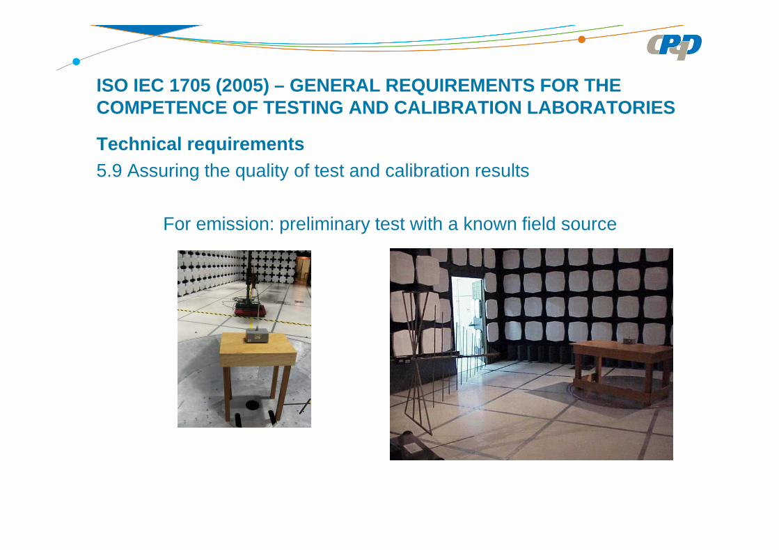
Technical requirements5.9 Assuring the quality of test and calibration results
• Proficiency testing• Interlaboratorial comparisons• Application of statistical techniques to critically analyze the results• Record the resulting data so that trends are identifiable• Preliminary tests with known sources of disturbances
ISO IEC 1705 (2005) – GENERAL REQUIREMENTS FOR THE COMPETENCE OF TESTING AND CALIBRATION LABORATORIES
Technical requirements5.9 Assuring the quality of test and calibration results
For emission: preliminary test with a known field source

ISO IEC 1705 (2005) – GENERAL REQUIREMENTS FOR THE COMPETENCE OF TESTING AND CALIBRATION LABORATORIES
Technical requirements5.10 Reporting the results
• Accurately and clearly unambiguously• Title• Name and address of the laboratory• Where these tests were done• Univocal identification of the report• Each page with an identification to ensure that the page is recognized as part of
the report.• Clear identification of the end of the report• Name and address of the customer• Identification of the method utilized• Description, condition and identification not ambiguous of the item tested• Date of receipt• Shall include all the information needed to interpret the result


![El método de Hückel simple - [DePa] Departamento de ...depa.fquim.unam.mx/amyd/archivero/Huckelsimple_21436.pdf · El determinante y la ecuación para los orbitales moleculares](https://static.fdocuments.us/doc/165x107/5bac130409d3f2e74b8d599e/el-metodo-de-hueckel-simple-depa-departamento-de-depafquimunammxamydarchiverohuckelsimple21436pdf.jpg)