ITT Mirror Steering System Team P11565 Andrew Bishop Katie Hall Matt Manelis Ben Geiger Nurkanat...
33
ITT Mirror Steering System Team P11565 Andrew Bishop Katie Hall Matt Manelis Ben Geiger Nurkanat Suttibayev
-
Upload
kathlyn-hall -
Category
Documents
-
view
215 -
download
0
Transcript of ITT Mirror Steering System Team P11565 Andrew Bishop Katie Hall Matt Manelis Ben Geiger Nurkanat...
ITT Mirror Steering System Team P11565
Andrew BishopKatie Hall
Matt ManelisBen Geiger
Nurkanat Suttibayev
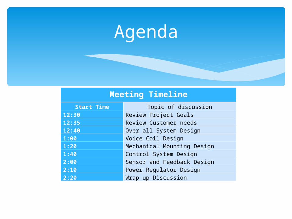
Meeting TimelineStart Time Topic of discussion
12:30 Review Project Goals12:35 Review Customer needs12:40 Over all System Design1:00 Voice Coil Design1:20 Mechanical Mounting Design1:40 Control System Design2:00 Sensor and Feedback Design2:10 Power Regulator Design2:20 Wrap up Discussion
Agenda

The mission of this project is to design and build a mirror steering system that can outperform commercially available systems in terms of Power Consumption.
This project will provide appropriate documentation that can be utilized by future senior design teams for further refinement.
Project Goals
The mirror steering system is a device that controls the angle of a mirror in two dimensions.
This device is used in directing optical devices at the mirror and aiming the mirror at an object located a far distance away.
The tilting of the mirror is achieved by the use of actuators, which push and pull the mirror into different locations.
Project Description
High Interaction between Mechanical and Electrical Designs which creates more design challenges
The goal is to compete with and do better than commercially available designs
The chance to work hands on with a design outside of our previous experiences.
Project Appeal
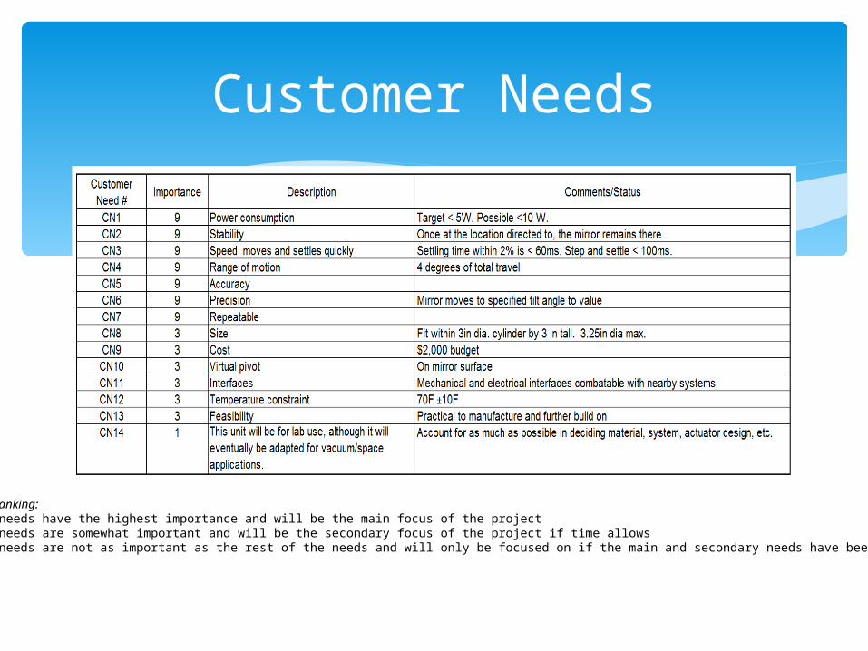
Customer Needs
Importance Ranking:9 – These needs have the highest importance and will be the main focus of the project3 – These needs are somewhat important and will be the secondary focus of the project if time allows1 – These needs are not as important as the rest of the needs and will only be focused on if the main and secondary needs have been satisfied
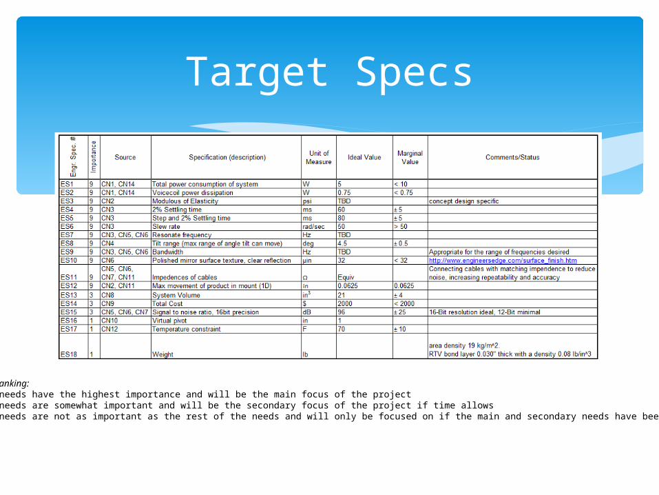
Target Specs
Importance Ranking:9 – These needs have the highest importance and will be the main focus of the project3 – These needs are somewhat important and will be the secondary focus of the project if time allows1 – These needs are not as important as the rest of the needs and will only be focused on if the main and secondary needs have been satisfied
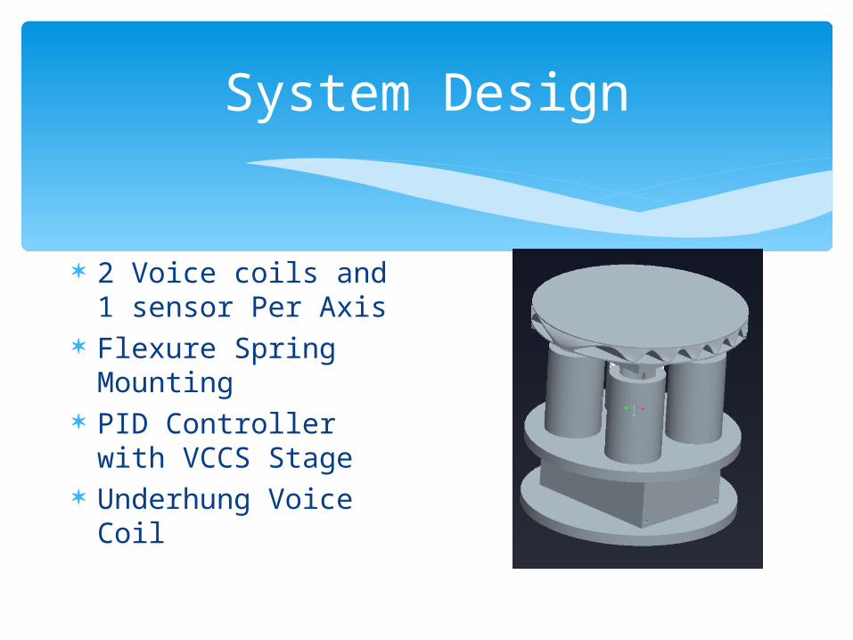
System Design
2 Voice coils and 1 sensor Per Axis
Flexure Spring Mounting
PID Controller with VCCS Stage
Underhung Voice Coil
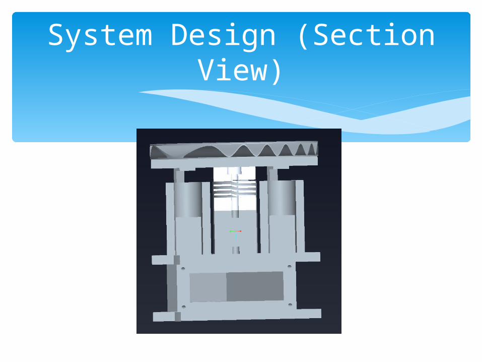
System Design (Section View)

Mechanical System Model
Model for Axis 1 (ө-direction)
X(t)
c1 c2k k
Jӫ
F1
L1 L1
L2 L2
ө
x
y
F1
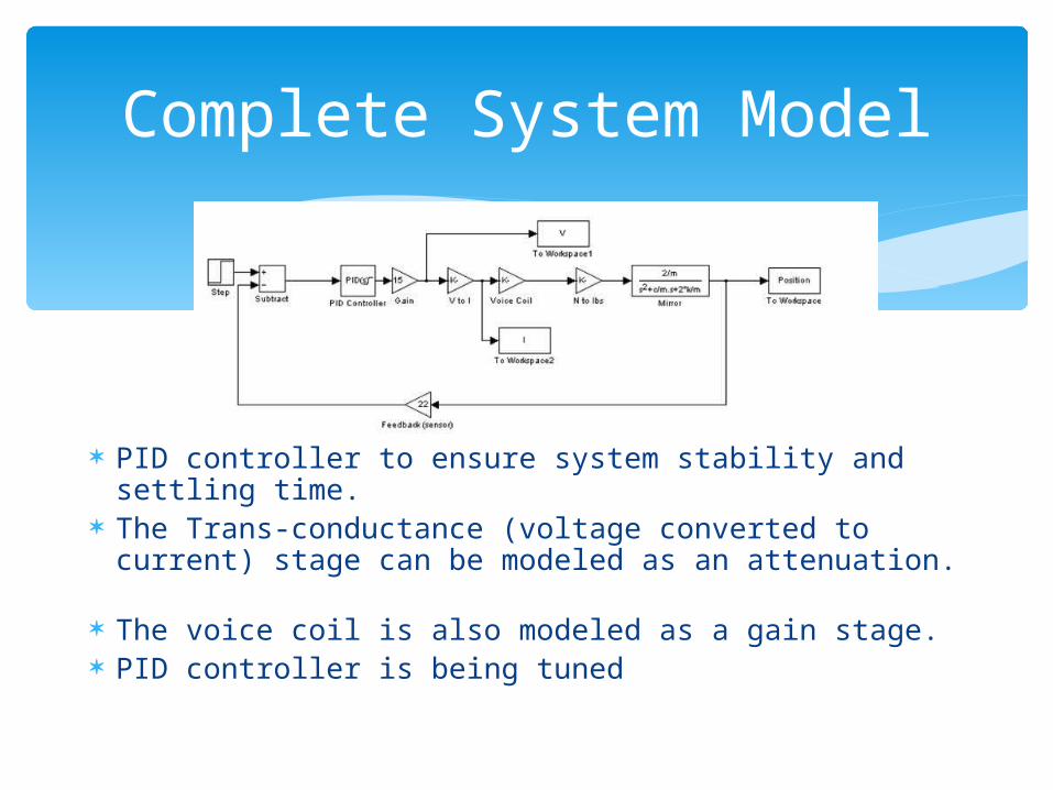
Complete System Model
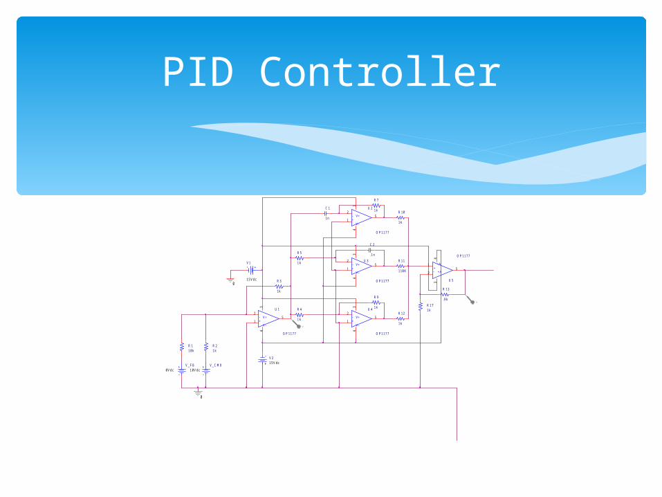
PID controller to ensure system stability and settling time.
The Trans-conductance (voltage converted to current) stage can be modeled as an attenuation.
The voice coil is also modeled as a gain stage. PID controller is being tuned
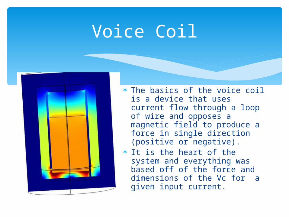
Voice Coil
The basics of the voice coil is a device that uses current flow through a loop of wire and opposes a magnetic field to produce a force in single direction (positive or negative).
It is the heart of the system and everything was based off of the force and dimensions of the Vc for a given input current.
The final design included 2 different voice coils, both with a 20mm outer diameter, one being 32mm tall, the other being about 22mm tall
The 22mm tall VC has a higher magnetic field of .33T field in the gap area, the taller one having .38T field.
Height not being too much of an issue for these gave us the choice to use the stronger field, and so giving more force for a given current.
Voice Coil Continued

Main assembly:- Waffle mirror (provided by ITT) attached to mirror mount by RTV adhesive- Flexure spring that allows system range of motion- Stem that connects the flexure to the top face of electronics box- Four actuators connected to mirror mount that will push and pull on mirror mount with generated force
Mechanical Design
Mirror Mount- CN8 (Size): The surface area of the mount is large enough to fit the flexure, voice coil contact point, and sensors, while not exceeding the diameter of the mirror- CN13 (Feasibility): The thickness is a standard value that can easily be purchased in stock (0.16’’)- ES3 (Modulus of Elasticity): Material must be stiff enough to withstand the forces and stresses imposed on part (6061 Aluminum)
Relating Design to Needs/Specs
To determine the displacement and stresses of the model, Finite Element Analysis is required
SolidWorks/COSMOS software used for FEA Two types of analyses performed
- Mirror and Flexure Structure- Electronics Box
Finite Element Analysis
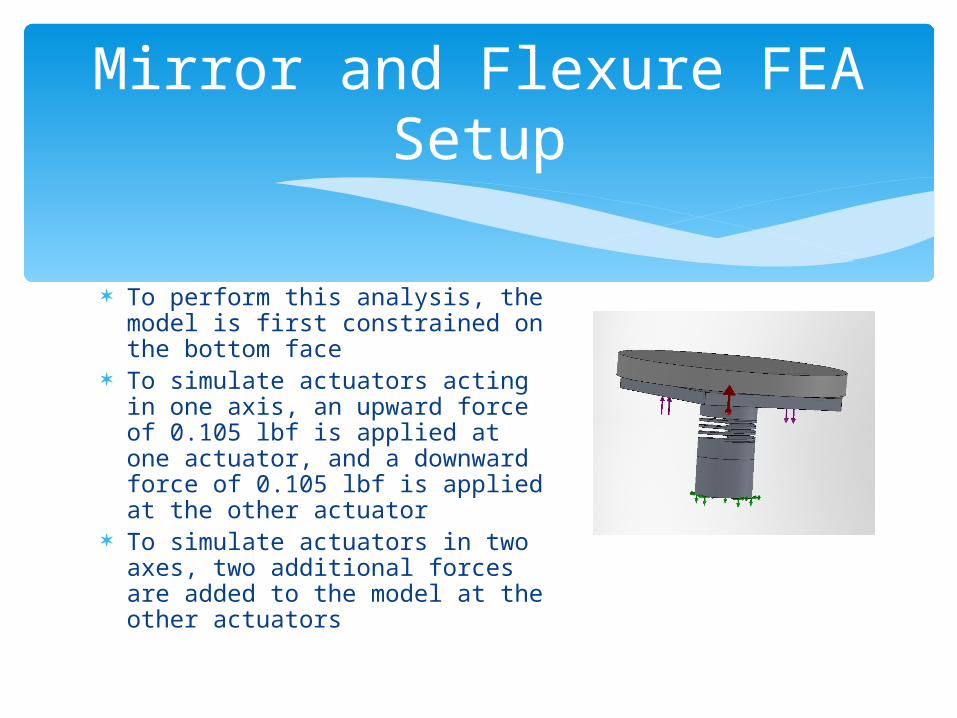
To perform this analysis, the model is first constrained on the bottom face
To simulate actuators acting in one axis, an upward force of 0.105 lbf is applied at one actuator, and a downward force of 0.105 lbf is applied at the other actuator
To simulate actuators in two axes, two additional forces are added to the model at the other actuators
Mirror and Flexure FEA Setup
Mirror and Flexure FEA Results
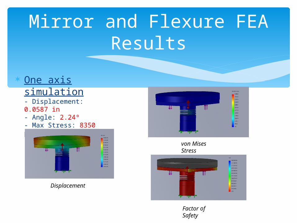
One axis simulation- Displacement: 0.0587 in- Angle: 2.24º- Max Stress: 8350 psi- FOS: 4.78
Displacement
von Mises Stress
Factor of Safety
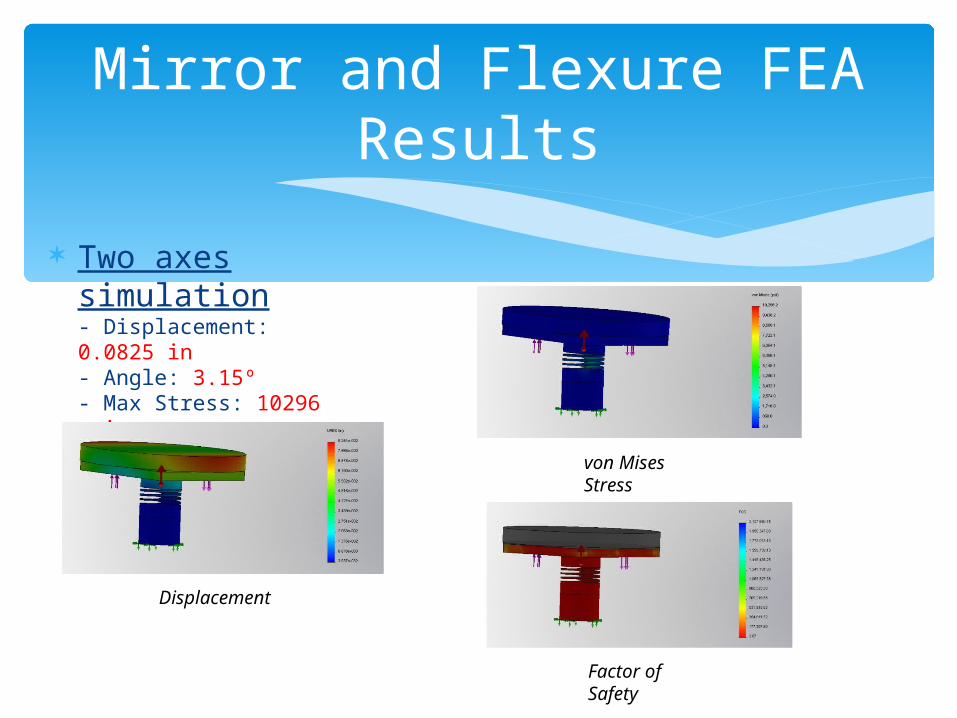
Mirror and Flexure FEA Results
Two axes simulation- Displacement: 0.0825 in- Angle: 3.15º- Max Stress: 10296 psi- FOS: 3.87
Displacement
von Mises Stress
Factor of Safety
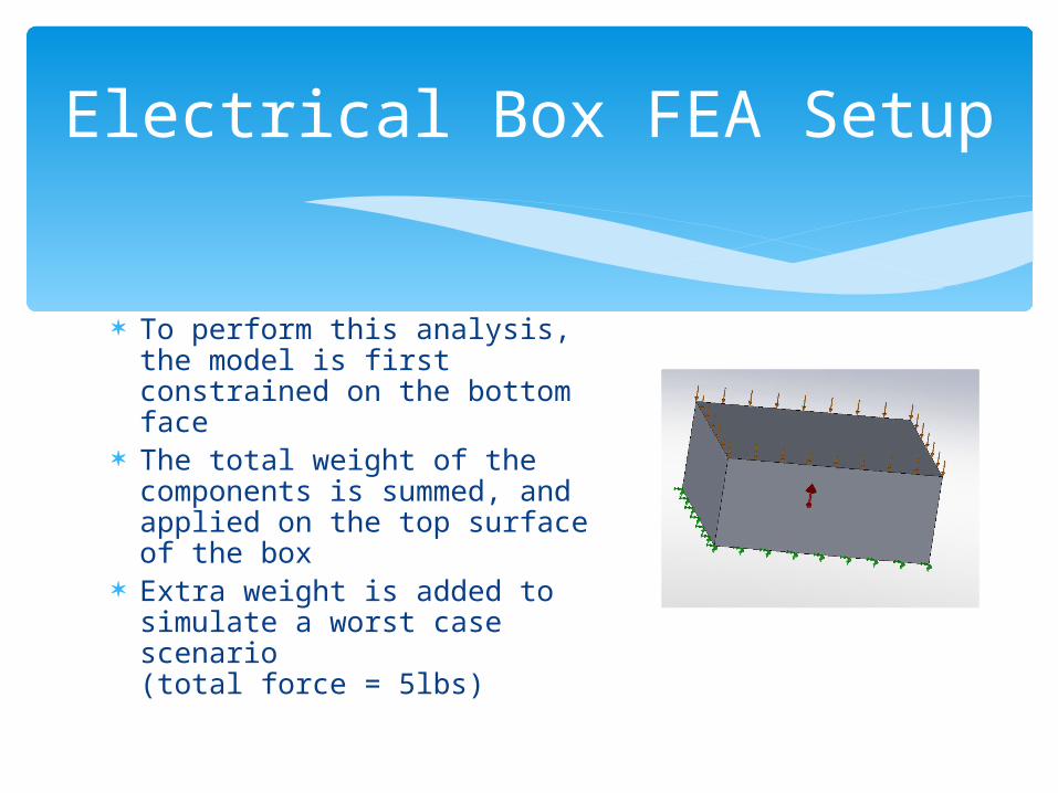
To perform this analysis, the model is first constrained on the bottom face
The total weight of the components is summed, and applied on the top surface of the box
Extra weight is added to simulate a worst case scenario (total force = 5lbs)
Electrical Box FEA Setup

Electrical Box FEA Results
Results:- Displacement: 1.37e-5 in- Max Stress: 64.4 psi- FOS: 619
Displacement
von Mises Stress
Factor of Safety
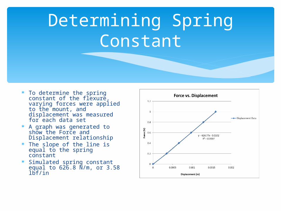
To determine the spring constant of the flexure, varying forces were applied to the mount, and displacement was measured for each data set
A graph was generated to show the Force and Displacement relationship
The slope of the line is equal to the spring constant
Simulated spring constant equal to 626.8 N/m, or 3.58 lbf/in
Determining Spring Constant
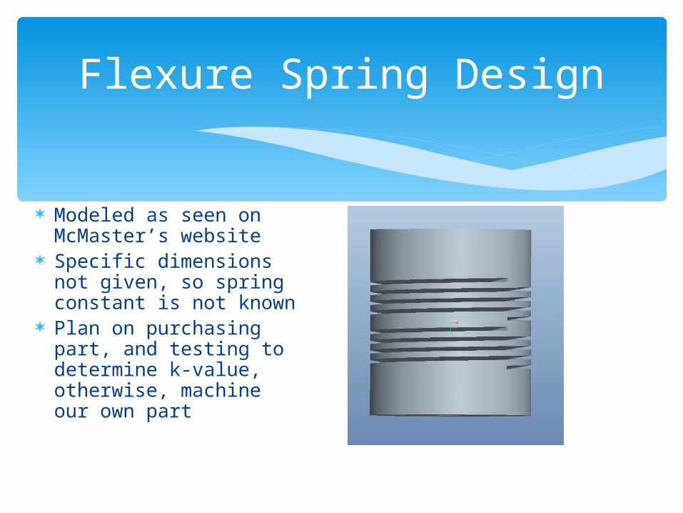
Flexure Spring Design
Modeled as seen on McMaster’s website
Specific dimensions not given, so spring constant is not known
Plan on purchasing part, and testing to determine k-value, otherwise, machine our own part
PID Controller
-+
V+
V-
U 1
O P 1 1 7 7
1
2
34
5
V 1
1 5 V d c
V 21 5 V d c
V _ C M D1 0 V d c
0
0
R 11 0 k
R 21 k
-+
V+
V-
U 2
O P 1 1 7 7
1
2
34
5
-+
V+
V-
U 3
O P 1 1 7 7
1
2
34
5
-+
V+
V-
U 4
O P 1 1 7 7
1
2
34
5
-+
V+
V-
U 5
O P 1 1 7 7
1
2
34
5
V _ F B0 V d c
R 1 3
. 9 k
R 3
1 k
C 2
. 1 n
R 4
1 k
R 5
1 k
C 1
1 n
R 7
1 k
R 9
1 k
R 1 0
1 k
R 1 1
1 1 0 K
R 1 2
1 k
R 1 71 k
V
V
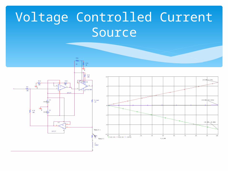
Voltage Controlled Current Source
0
V 41 5 V d c
V 51 5 V d c
0
R _ I s e t2 5
U 8
O P A 5 4 7 / B B+1
-2 I L im
3V -
4
V +5
V o6
E / S7
R 2 1
2 kR 2 24 k
0
R 2 31 0 0
I
L 14 2 0 u H
1
2
Theta X +
Theta X -
-+
V+
V-
U 6
O P 1 7 7
1
2
34
5
-+
V+
V-
U 7
O P 1 7 7
1
2
34
5
R 8
1 0 k
R 1 4
1 0 k
R 1 5
1 k
R 1 81 0 k
R 1 92 5
V_V_CMD
0V 1V 2V 3V 4V 5V 6V 7V 8V 9V 10VV(U1:34) V(U5:34) -I(R19)
-12
-8
-4
0
4
8
12
(10.000,-10.000)
(10.000,9.578)
(10.000,145.345m)

Sensor Design
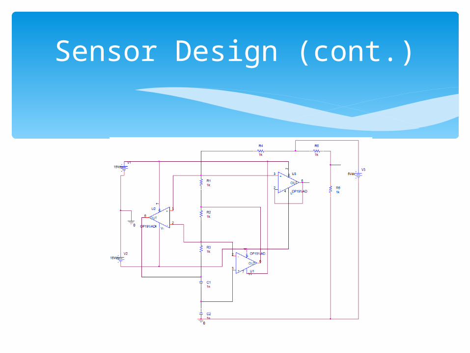
The sensor is based on the idea of a varying capacitance by using 2 metal plates close to each other
One is stationary while the other moves with the mirror moves.
As the plate moves the capacitance changes and changed the impedance of the circuit.
An Impedance converter creates an equivalent resistance.
A Wheatstone bridge circuit is used to find the variation of the impedance in terms of a voltage.
The voltage VG Is then supplied back to the control circuitry to use as feedback.
Sensor Design (cont.)

Power Regulator
IN
ADJ
OUT
U 2
L M 3 3 7 K
1
2
3
V 1
A C = 6TR A N =
D C = 2 4
V 2
A C = 6TR A N =
D C = -2 4R 15 0 0
R 25 . 6 3 k
R 35 0 0
R 45 . 3 6 k
0
C 1. 1 u
C 21 0 0 u
C 3. 1 u
C 41 5 0 u
U 3L M 3 1 7 K
I N2
O U T3
AD
J1
V
V
Frequency
10mHz 100mHz 1.0Hz 10Hz 100Hz 1.0KHz 10KHz 100KHz 1.0MHzV(U3:OUT) V(U2:19)
0V
50mV
100mV
150mV
(362.611,141.542m)
(1.6033K,6.0046m)
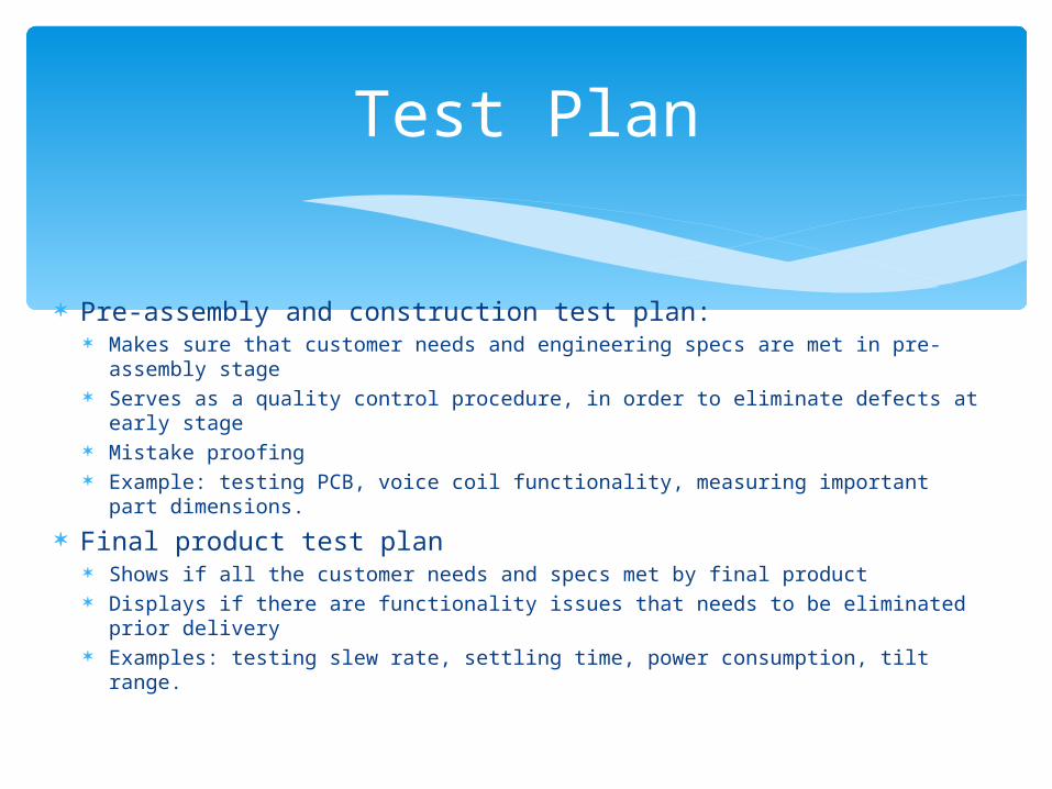
Pre-assembly and construction test plan: Makes sure that customer needs and engineering specs are met in pre-
assembly stage Serves as a quality control procedure, in order to eliminate defects at early
stage Mistake proofing Example: testing PCB, voice coil functionality, measuring important part
dimensions.
Final product test plan Shows if all the customer needs and specs met by final product Displays if there are functionality issues that needs to be eliminated prior
delivery Examples: testing slew rate, settling time, power consumption, tilt range.
Test Plan
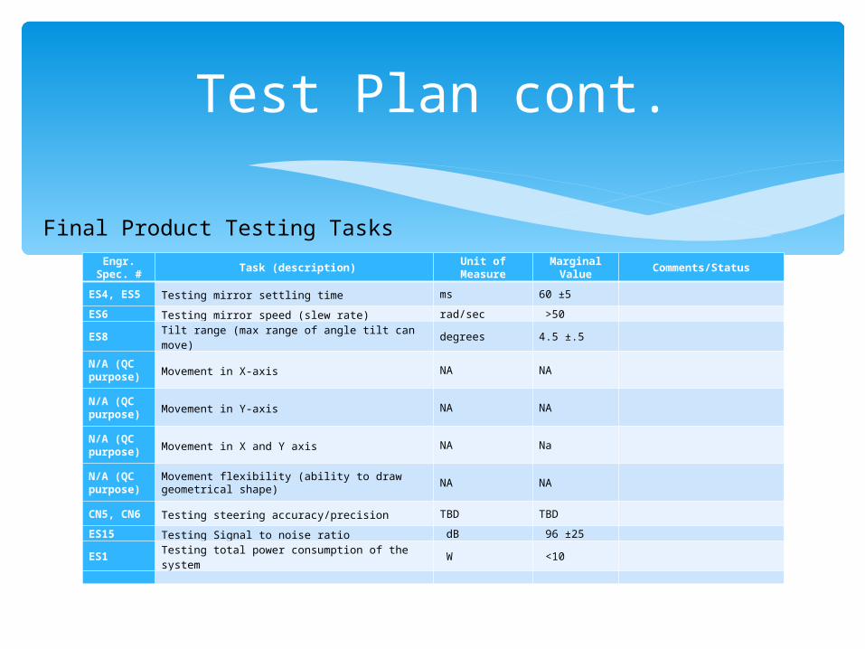
Engr. Spec. #
Task (description)Unit of
MeasureMarginal
ValueComments/Status
ES4, ES5 Testing mirror settling time ms 60 ±5
ES6 Testing mirror speed (slew rate) rad/sec >50
ES8 Tilt range (max range of angle tilt can move) degrees 4.5 ±.5
N/A (QC purpose) Movement in X-axis NA NA
N/A (QC purpose) Movement in Y-axis NA NA
N/A (QC purpose) Movement in X and Y axis NA Na
N/A (QC purpose)
Movement flexibility (ability to draw geometrical shape)
NA NA
CN5, CN6 Testing steering accuracy/precision TBD TBD
ES15 Testing Signal to noise ratio dB 96 ±25
ES1 Testing total power consumption of the system W <10
Test Plan cont.
Final Product Testing Tasks

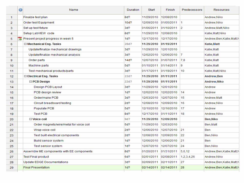
MSD II Project Plan
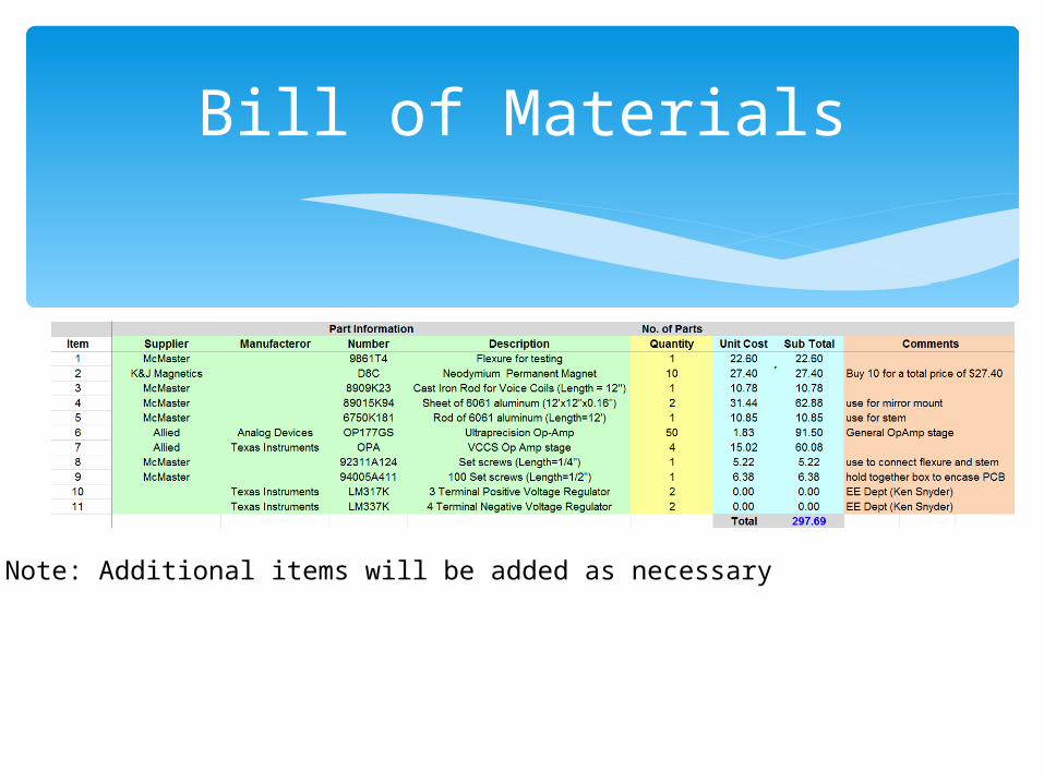
Bill of Materials
Note: Additional items will be added as necessary


![Geiger 2011 Presentation[1]](https://static.fdocuments.us/doc/165x107/555e97f3d8b42a6d068b4d4c/geiger-2011-presentation1.jpg)