its-telecom.co.il voip gateways/PRI... · Version 5.2 3 September 2007 SIP User's Manual Contents...
404
Document #: LTRT-68806 September 2007 User's Manual Version 5.2
Transcript of its-telecom.co.il voip gateways/PRI... · Version 5.2 3 September 2007 SIP User's Manual Contents...

Document #: LTRT-68806 September 2007
User's Manual Version 5.2


Version 5.2 3 September 2007
SIP User's Manual Contents
Table of Contents
1 Overview ............................................................................................................15
1.1 SIP Overview .........................................................................................................15 1.2 Mediant 2000 Overview .........................................................................................15 1.3 TP-1610 Overview .................................................................................................17 1.4 TP-260 Overview ...................................................................................................18
2 Physical Description.........................................................................................19
2.1 Mediant 2000 Physical Description ........................................................................19 2.1.1 Mediant 2000 Chassis .............................................................................................20 2.1.2 Power Supply...........................................................................................................20 2.1.3 Optional CPU Blade.................................................................................................21
2.2 TP-1610 Physical Description ................................................................................21 2.2.1 TP-1610 Front Panel LEDs .....................................................................................22 2.2.2 TP-1610 Rear Transition Module ............................................................................23
2.3 TP-260 Physical Description ..................................................................................25 2.3.1 TP-260 LEDs ...........................................................................................................26 2.3.2 TP-260 Ethernet and E1/T1 Ports ...........................................................................27
3 Installation .........................................................................................................29
3.1 Installing the Mediant 2000 ....................................................................................29 3.1.1 Unpacking................................................................................................................29 3.1.2 Package Contents ...................................................................................................30 3.1.3 Mounting the Mediant 2000 .....................................................................................30
3.1.3.1 Mounting Mediant 2000 on a Desktop .................................................... 31 3.1.3.2 Installing Mediant 2000 in a 19-inch Rack .............................................. 31
3.1.4 Cabling the Mediant 2000........................................................................................33 3.1.4.1 Grounding the Mediant 2000................................................................... 35 3.1.4.2 Connecting the E1/T1 Trunk Interfaces .................................................. 35 3.1.4.3 Connecting the Ethernet Interface .......................................................... 36 3.1.4.4 Connecting the RS-232 Port to a PC ...................................................... 37 3.1.4.5 Connecting the Power Supply................................................................. 38
3.2 Installing the TP-1610 ............................................................................................40 3.2.1 Unpacking................................................................................................................40 3.2.2 Package Contents ...................................................................................................41 3.2.3 Installing the TP-1610..............................................................................................41
3.2.3.1 Inserting Blades....................................................................................... 41 3.2.3.2 Removing Blades .................................................................................... 42
3.2.4 Cabling the TP-1610................................................................................................42 3.3 Installing the TP-260 ..............................................................................................43
3.3.1 Unpacking................................................................................................................43 3.3.2 Package Contents ...................................................................................................44 3.3.3 Installing the TP-260................................................................................................44 3.3.4 Cabling the TP-260..................................................................................................44
3.3.4.1 Connecting the E1/T1 Trunk Interfaces .................................................. 45 3.3.4.2 Connecting the Ethernet Interface .......................................................... 46

SIP User's Manual 4 Document #: LTRT-68806
Mediant 2000 & TP-1610 & TP-260/UNI
4 Getting Started ..................................................................................................47
4.1 Configuration Concepts..........................................................................................47 4.2 Startup Process......................................................................................................48 4.3 Assigning an IP Address ........................................................................................50
4.3.1 Assigning an IP Address Using HTTP.....................................................................50 4.3.2 Assigning an IP Address Using BootP ....................................................................51 4.3.3 Assigning an IP Address Using the CLI...................................................................51
4.3.3.1 Accessing the CLI ................................................................................... 52 4.3.3.2 Assigning an IP Address ......................................................................... 53
4.4 Configuring Basic Parameters ...............................................................................54
5 Web-based Management ..................................................................................57
5.1 Computer Requirements ........................................................................................57 5.2 Protection and Security Mechanisms.....................................................................57
5.2.1 User Accounts .........................................................................................................58 5.2.2 Limiting the Embedded Web Server to Read-Only Mode .......................................59 5.2.3 Disabling the Embedded Web Server .....................................................................59
5.3 Accessing the Embedded Web Server ..................................................................60 5.4 Getting Acquainted with the Web Interface............................................................61
5.4.1 Main Menu Bar ........................................................................................................62 5.4.2 Saving Changes ......................................................................................................62 5.4.3 Entering Phone Numbers in Various Tables ...........................................................62 5.4.4 Searching for Configuration Parameters .................................................................63 5.4.5 Customizing the Web Interface ...............................................................................65
5.4.5.1 Replacing the Main Corporate Logo ....................................................... 65 5.4.5.2 Replacing the Background Image File .................................................... 68 5.4.5.3 Customizing the Product Name .............................................................. 69 5.4.5.4 Creating a Login Welcome Message ...................................................... 70
5.5 Protocol Management ............................................................................................71 5.5.1 Protocol Definition Parameters................................................................................71
5.5.1.1 General Parameters ................................................................................ 72 5.5.1.2 Proxy & Registration Parameters............................................................ 86 5.5.1.3 Coders..................................................................................................... 96 5.5.1.4 DTMF & Dialing Parameters ................................................................... 99
5.5.2 Configuring the Advanced Parameters................................................................. 102 5.5.2.1 General Parameters .............................................................................. 103 5.5.2.2 Supplementary Services ....................................................................... 109 5.5.2.3 Stand-Alone Survivability ...................................................................... 111
5.5.3 Configuring the Number Manipulation Tables ...................................................... 113 5.5.3.1 Dialing Plan Notation............................................................................. 116 5.5.3.2 Numbering Plans and Type of Number................................................. 117 5.5.3.3 Mapping NPI/TON to Phone-Context.................................................... 118
5.5.4 Configuring the Routing Tables ............................................................................ 120 5.5.4.1 General Parameters .............................................................................. 120 5.5.4.2 Tel to IP Routing Table.......................................................................... 122 5.5.4.3 IP to Trunk Group Routing .................................................................... 126 5.5.4.4 Internal DNS Table................................................................................ 128 5.5.4.5 Internal SRV Table ................................................................................ 129 5.5.4.6 Reasons for Alternative Routing ........................................................... 130 5.5.4.7 Release Cause Mapping....................................................................... 132

Version 5.2 5 September 2007
SIP User's Manual Contents
5.5.5 Configuring the Profile Definitions ........................................................................ 132 5.5.5.1 Coder Group Settings............................................................................ 133 5.5.5.2 Tel Profile Settings ................................................................................ 134 5.5.5.3 IP Profile Settings.................................................................................. 136
5.5.6 Configuring the Trunk Group Table ...................................................................... 138 5.5.7 Configuring the Trunk Group Settings .................................................................. 140 5.5.8 Configuring the Digital Gateway Parameters ....................................................... 142 5.5.9 Configuring the Advanced Applications................................................................ 147
5.5.9.1 Configuring RADIUS Accounting Parameters....................................... 147 5.5.9.2 Configuring the Voice Mail (VM) Parameters........................................ 149
5.6 Network Settings ..................................................................................................152 5.6.1 Configuring the IP Settings................................................................................... 153 5.6.2 Configuring the Application Settings..................................................................... 157 5.6.3 Configuring the NFS Settings ............................................................................... 159 5.6.4 Configuring the IP Routing Table ......................................................................... 162 5.6.5 Configuring the VLAN Settings............................................................................. 164
5.7 Media Settings .....................................................................................................166 5.7.1 Configuring the Voice Settings ............................................................................. 166 5.7.2 Configuring the Fax / Modem / CID Settings........................................................ 168 5.7.3 Configuring the RTP / RTCP Settings .................................................................. 172 5.7.4 Configuring the IPmedia Settings ......................................................................... 176 5.7.5 Configuring the General Media Settings............................................................... 177
5.8 PSTN Settings......................................................................................................178 5.8.1 Configuring the PSTN Settings............................................................................. 178
5.8.1.1 Trunk Settings ....................................................................................... 178 5.8.1.2 CAS State Machines ............................................................................. 192
5.8.2 Configuring the TDM Bus Settings ....................................................................... 195 5.9 Security Settings ..................................................................................................197
5.9.1 Configuring the Web User Accounts .................................................................... 197 5.9.2 Configuring the Web and Telnet Access List........................................................ 199 5.9.3 Configuring the Firewall Settings.......................................................................... 200 5.9.4 Configuring the Certificates .................................................................................. 202
5.9.4.1 Server Certificate Replacement ............................................................ 202 5.9.4.2 Client Certificates .................................................................................. 203 5.9.4.3 Self-Signed Certificates......................................................................... 204
5.9.5 Configuring the General Security Settings ........................................................... 206 5.9.6 Configuring the IPSec Table................................................................................. 210 5.9.7 Configuring the IKE Table .................................................................................... 214
5.10 Configuring the Management Settings.................................................................218 5.10.1 Configuring the SNMP Trap Destinations Table .................................................. 221 5.10.2 Configuring the SNMP Community Strings .......................................................... 222 5.10.3 Configuring SNMP V3 Users ................................................................................ 224
5.11 Status & Diagnostics ............................................................................................226 5.11.1 Gateway Statistics ................................................................................................ 226
5.11.1.1 IP Connectivity ...................................................................................... 226 5.11.1.2 Call Counters......................................................................................... 228 5.11.1.3 Call Routing Status................................................................................ 231 5.11.1.4 SAS Registered Users .......................................................................... 232
5.11.2 Activating the Internal Syslog Viewer ................................................................... 233 5.11.3 Device Information................................................................................................ 234 5.11.4 Viewing the Ethernet Port Information.................................................................. 235 5.11.5 Viewing Performance Statistics ............................................................................ 235

SIP User's Manual 6 Document #: LTRT-68806
Mediant 2000 & TP-1610 & TP-260/UNI
5.11.6 Channel Status ..................................................................................................... 236 5.11.6.1 Viewing Trunk Port Settings.................................................................. 237 5.11.6.2 Assigning a Port Name.......................................................................... 238 5.11.6.3 Viewing Channel Information ................................................................ 239
5.12 Software Update ..................................................................................................240 5.12.1 Software Upgrade Wizard..................................................................................... 240 5.12.2 Automatic Update Mechanism.............................................................................. 245 5.12.3 Auxiliary Files........................................................................................................ 247
5.12.3.1 Loading the Auxiliary Files via the Embedded Web Server .................. 248 5.12.3.2 Loading the Auxiliary Files via the ini File ............................................. 249
5.12.4 Updating the Software Upgrade Key .................................................................... 249 5.12.4.1 Backing up the Current Software Upgrade Key .................................... 250 5.12.4.2 Loading the Software Upgrade Key ...................................................... 250 5.12.4.3 Verifying that the Key was Successfully Loaded .................................. 253 5.12.4.4 Troubleshooting an Unsuccessful Loading of a Key............................. 253
5.13 Maintenance.........................................................................................................254 5.13.1 Regional Settings.................................................................................................. 254 5.13.2 Locking and Unlocking the Gateway .................................................................... 254 5.13.3 Saving Configuration ............................................................................................ 256 5.13.4 Resetting the Gateway ......................................................................................... 257 5.13.5 Restoring and Backing up Configuration.............................................................. 258 5.13.6 Factory Default Settings ....................................................................................... 259
5.13.6.1 Defining Default Values......................................................................... 259 5.13.6.2 Restoring Default Settings .................................................................... 260
5.14 Using the Home Page ..........................................................................................260 5.14.1 Accessing the Home Page ................................................................................... 261 5.14.2 Switching between Mediant 2000 Modules .......................................................... 262 5.14.3 Viewing Ethernet Port Information........................................................................ 262 5.14.4 Viewing the Active Alarms Table .......................................................................... 263 5.14.5 Viewing Trunk Settings......................................................................................... 264 5.14.6 Assigning a Name to a Port .................................................................................. 266
5.15 Logging Off the Embedded Web Server ..............................................................266
6 ini File Configuration ......................................................................................267
6.1 Secured ini File ....................................................................................................267 6.2 Modifying an ini File .............................................................................................267 6.3 The ini File Content ..............................................................................................268 6.4 The ini File Structure ............................................................................................268
6.4.1 The ini File Structure Rules .................................................................................. 269 6.4.2 Structure of Individual ini File Parameters............................................................ 269 6.4.3 Structure of ini File Parameter Tables .................................................................. 269 6.4.4 The ini File Example ............................................................................................. 272
6.5 The ini File Parameter Reference ........................................................................272 6.5.1 Networking Parameters ........................................................................................ 273 6.5.2 System Parameters .............................................................................................. 280 6.5.3 Web and Telnet Parameters................................................................................. 287 6.5.4 Security Parameters ............................................................................................. 290 6.5.5 RADIUS Parameters............................................................................................. 291 6.5.6 SNMP Parameters................................................................................................ 293 6.5.7 SIP Configuration Parameters.............................................................................. 295 6.5.8 Media Server Parameters..................................................................................... 306 6.5.9 Voice Mail Parameters.......................................................................................... 306 6.5.10 PSTN Parameters................................................................................................. 307 6.5.11 ISDN and CAS Interworking-Related Parameters................................................ 311

Version 5.2 7 September 2007
SIP User's Manual Contents
6.5.12 Number Manipulation and Routing Parameters ................................................... 318 6.5.13 Channel Parameters............................................................................................. 332 6.5.14 Configuration Files Parameters ............................................................................ 337
7 Telephony Capabilities ...................................................................................339
7.1 Configuring the DTMF Transport Types...............................................................339 7.2 Fax and Modem Capabilities................................................................................340
7.2.1 Fax/Modem Operating Modes .............................................................................. 340 7.2.2 Fax/Modem Transport Modes .............................................................................. 341
7.2.2.1 T.38 Fax Relay Mode............................................................................ 341 7.2.2.2 Fax/Modem Bypass Mode .................................................................... 342 7.2.2.3 Fax / Modem NSE Mode....................................................................... 343 7.2.2.4 G.711 Fax / Modem Transport Mode.................................................... 344 7.2.2.5 Fax Fallback .......................................................................................... 344 7.2.2.6 Fax / Modem Transparent Mode........................................................... 345 7.2.2.7 Fax / Modem Transparent with Events Mode ....................................... 345
7.2.3 Supporting V.34 Faxes ......................................................................................... 346 7.2.3.1 Using Bypass Mechanism for V.34 Fax Transmission.......................... 346 7.2.3.2 Using Relay mode for both T.30 and V.34 faxes .................................. 346
7.2.4 Supporting V.152 Implementation ........................................................................ 347 7.3 Event Notification using X-Detect Header............................................................348 7.4 RTP Multiplexing (ThroughPacket) ......................................................................349 7.5 Dynamic Jitter Buffer Operation ...........................................................................350 7.6 Configuring Alternative Routing (Based on Connectivity and QoS) .....................351
7.6.1 Alternative Routing Mechanism............................................................................ 351 7.6.2 Determining the Availability of Destination IP Addresses..................................... 351 7.6.3 PSTN Fallback as a Special Case of Alternative Routing .................................... 352 7.6.4 Relevant Parameters ............................................................................................ 352
7.7 Call Detail Record ................................................................................................352 7.8 Supported RADIUS Attributes..............................................................................354
7.8.1 RADIUS Server Messages ................................................................................... 356 7.9 Trunk-to-Trunk Routing Example .........................................................................356 7.10 Proxy or Registrar Registration Example .............................................................357 7.11 Configuration Examples .......................................................................................358
7.11.1 SIP Call Flow ........................................................................................................ 358 7.11.2 SIP Authentication Example ................................................................................. 361
7.12 Working with Supplementary Services.................................................................363 7.12.1 Call Hold and Retrieve.......................................................................................... 363 7.12.2 Call Transfer ......................................................................................................... 364
8 Networking Capabilities..................................................................................365
8.1 Ethernet Interface Configuration ..........................................................................365 8.2 Ethernet Interface Redundancy ...........................................................................365 8.3 NAT (Network Address Translation) Support.......................................................366
8.3.1 STUN .................................................................................................................... 367 8.3.2 First Incoming Packet Mechanism........................................................................ 368 8.3.3 No-Op Packets ..................................................................................................... 368

SIP User's Manual 8 Document #: LTRT-68806
Mediant 2000 & TP-1610 & TP-260/UNI
8.4 Point-to-Point Protocol over Ethernet (PPPoE)....................................................369 8.4.1 Point-to-Point Protocol (PPP) Overview............................................................... 369 8.4.2 PPPoE Overview .................................................................................................. 370 8.4.3 PPPoE in AudioCodes gateway ........................................................................... 370
8.5 IP Multicasting......................................................................................................371 8.6 Robust Reception of RTP Streams ......................................................................371 8.7 Multiple Routers Support......................................................................................371 8.8 Simple Network Time Protocol Support ...............................................................372 8.9 IP QoS via Differentiated Services (DiffServ).......................................................372 8.10 VLANS and Multiple IPs.......................................................................................373
8.10.1 Multiple IPs ........................................................................................................... 373 8.10.2 IEEE 802.1p/Q (VLANs and Priority).................................................................... 373 8.10.3 Getting Started with VLANS and Multiple IPs ...................................................... 376
8.10.3.1 Integrating Using the Embedded Web Server ...................................... 376 8.10.3.2 Integrating Using the ini File.................................................................. 380
9 Advanced PSTN Configuration ......................................................................381
9.1 Clock Settings ......................................................................................................381 9.2 Release Reason Mapping....................................................................................382
9.2.1 Reason Header..................................................................................................... 382 9.2.2 Fixed Mapping of ISDN Release Reason to SIP Response................................. 383 9.2.3 Fixed Mapping of SIP Response to ISDN Release Reason................................. 385
9.3 ISDN Overlap Dialing ...........................................................................................386 9.4 Using ISDN NFAS................................................................................................387
9.4.1 NFAS Interface ID................................................................................................. 387 9.4.2 Working with DMS-100 Switches ......................................................................... 388 9.4.3 Creating an NFAS-Related Trunk Configuration On-The-Fly............................... 389
9.5 Redirect Number and Calling Name (Display) .....................................................390
10 Tunneling Applications...................................................................................391
10.1 TDM Tunneling.....................................................................................................391 10.1.1 Implementation ..................................................................................................... 391
10.2 QSIG Tunneling ...................................................................................................394 10.2.1 Implementation ..................................................................................................... 394
11 Selected Technical Specifications.................................................................395
11.1 General Specifications .........................................................................................395 11.2 Mediant 2000 Specifications ................................................................................397 11.3 TP-1610 Specifications ........................................................................................399 11.4 TP-260 Specifications ..........................................................................................401
12 Supplied SIP Software Package.....................................................................403

Version 5.2 9 September 2007
SIP User's Manual Contents
List of Figures Figure 1-1: Mediant 2000 Typical Application ........................................................................................16 Figure 2-1: Mediant 2000 Front Panel....................................................................................................19 Figure 2-2: Front View of TP-1610 cPCI Blade......................................................................................21 Figure 2-3: RTM-1610 Rear Panel with two 50-pin Connectors for 16 Trunks ......................................24 Figure 2-4: RTM-1610 with 8 RJ-48c Connectors for 8 Trunks .............................................................24 Figure 2-5: TP-260 Board Description....................................................................................................25 Figure 2-6: RJ-45 Connector Pinouts.....................................................................................................27 Figure 2-7: RJ-48c Connector Pinouts ...................................................................................................27 Figure 3-1: 19-inch Rack and Desktop Accessories ..............................................................................30 Figure 3-2: Front View with 19-inch Rack-Mount Brackets ....................................................................32 Figure 3-3: Rear-Panel Cabling (e.g., 16 Trunks, Dual AC Power) .......................................................33 Figure 3-4: Rear-Panel Cabling (8 Trunks, DC Power)..........................................................................34 Figure 3-5: 50-pin Female Telco Board-Mounted Connector.................................................................35 Figure 3-6: RJ-48c Connector Pinouts ...................................................................................................36 Figure 3-7: RJ-45 Connector Pinouts.....................................................................................................37 Figure 3-8: RS-232 Connector Pinouts ..................................................................................................37 Figure 3-9: DC Power Terminal Block Screw Connector .......................................................................39 Figure 3-10: DC Power Terminal Block Crimp Connector .....................................................................39 Figure 3-11: RJ-48c Connector Pinouts .................................................................................................45 Figure 3-12: E1/T1 Cable Splitter...........................................................................................................45 Figure 3-13: RJ-45 Connector Pinouts...................................................................................................46 Figure 4-1: Startup Process....................................................................................................................49 Figure 4-2: Quick Setup Screen .............................................................................................................54 Figure 5-1: Enter Network Password Screen.........................................................................................60 Figure 5-2: Searched Result Screen ......................................................................................................63 Figure 5-3: Searched Parameter Highlighted in Screen ........................................................................64 Figure 5-4: Customized Web Interface Title Bar ....................................................................................65 Figure 5-5: Customized Web Interface Title Bar ....................................................................................65 Figure 5-6: Image Download Screen......................................................................................................66 Figure 5-7: User-Defined Web Welcome Message after Login..............................................................70 Figure 5-8: General Parameters (Protocol Definition Submenu) ...........................................................72 Figure 5-9: Proxy & Registration Screen................................................................................................86 Figure 5-10: Coders Screen ...................................................................................................................96 Figure 5-11: DTMF & Dialing Screen .....................................................................................................99 Figure 5-12: Stand-Alone Survivability Screen.................................................................................... 112 Figure 5-13: Source Phone Number Manipulation Table for Tel-to-IP Calls....................................... 114 Figure 5-14: Phone Context Table Screen.......................................................................................... 118 Figure 5-15: Routing Tables - General Parameters Screen................................................................ 120 Figure 5-16: Tel to IP Routing Table Screen....................................................................................... 124 Figure 5-17: IP to Trunk Group Routing Table Screen ....................................................................... 127 Figure 5-18: Internal DNS Table Screen ............................................................................................. 129 Figure 5-19: Internal SRV Table Screen ............................................................................................. 130 Figure 5-20: Reasons for Alternative Routing Screen......................................................................... 131 Figure 5-21: Release Cause Mapping Screen (e.g., ISDN to SIP) ..................................................... 132 Figure 5-22: Coder Group Settings Screen......................................................................................... 133 Figure 5-23: IP Profile Settings Screen ............................................................................................... 137 Figure 5-24: Trunk Group Table Screen ............................................................................................. 138 Figure 5-25: Trunk Group Settings Screen ......................................................................................... 140 Figure 5-26: Digital Gateway Parameters Screen............................................................................... 142 Figure 5-27: RADIUS Parameters Screen .......................................................................................... 148 Figure 5-28: IP Settings Screen .......................................................................................................... 153 Figure 5-29: Application Settings Screen............................................................................................ 157 Figure 5-30: NFS Settings Screen ...................................................................................................... 160 Figure 5-31: IP Routing Tablre Screen................................................................................................ 162 Figure 5-32: VLAN Settings Screen .................................................................................................... 164

SIP User's Manual 10 Document #: LTRT-68806
Mediant 2000 & TP-1610 & TP-260/UNI
Figure 5-33: Voice Settings Screen..................................................................................................... 166 Figure 5-34: Fax / Modem / CID Settings Screen ............................................................................... 168 Figure 5-35: IPmedia Settings Screen ................................................................................................ 176 Figure 5-36: General Media Settings Screen...................................................................................... 177 Figure 5-37: CAS State Machine Table Screen .................................................................................. 192 Figure 5-38: TDM Bus Settings Screen............................................................................................... 195 Figure 5-39: Web User Accounts Screen (for Users with 'Security Administrator' Privileges)............ 198 Figure 5-40: Web & Telnet Access List Screen................................................................................... 199 Figure 5-41: Firewall Settings Screen ................................................................................................. 200 Figure 5-42: Certificates Signing Request Screen .............................................................................. 202 Figure 5-43: IPSec Table Screen ........................................................................................................ 210 Figure 5-44: IKE Table Screen............................................................................................................ 214 Figure 5-45: SNMP Trap Destinations Screen.................................................................................... 221 Figure 5-46: SNMP Community Strings Screen.................................................................................. 223 Figure 5-47: SNMP V3 Setting Screen................................................................................................ 224 Figure 5-48: IP Connectivity Screen.................................................................................................... 227 Figure 5-49: Calls Count Screen (e.g., Tel to IP) ................................................................................ 229 Figure 5-50: Call Routing Status Screen............................................................................................. 231 Figure 5-51: SAS Registered Users Screen........................................................................................ 232 Figure 5-52: Message Log Screen ...................................................................................................... 233 Figure 5-53: Device Information Screen.............................................................................................. 234 Figure 5-54: Ethernet Port Information Screen ................................................................................... 235 Figure 5-55: Basic Statistics Screen ................................................................................................... 236 Figure 5-56: Trunk & Channel Status Screen ..................................................................................... 236 Figure 5-57: Shortcut Menu for Viewing Trunk Settings ..................................................................... 237 Figure 5-58: Shortcut Menu for Assigning a Port Name ..................................................................... 238 Figure 5-59: Basic Information Screen................................................................................................ 239 Figure 5-60: Start Software Upgrade Wizard Screen.......................................................................... 241 Figure 5-61: End Process Wizard Screen ........................................................................................... 244 Figure 5-62: Software Upgrade Key with Multiple S/N Lines .............................................................. 252 Figure 5-63: Regional Settings Screen ............................................................................................... 254 Figure 5-64: Maintenance Actions Screen .......................................................................................... 255 Figure 5-65: Maintenance Actions Screen .......................................................................................... 256 Figure 5-66: Maintenance Actions Screen .......................................................................................... 257 Figure 5-67: Configuration File Screen ............................................................................................... 258 Figure 5-68: Home Page ..................................................................................................................... 261 Figure 5-69: Confirmation Message Box for Switching Modules ........................................................ 262 Figure 5-70: Ethernet Port Information Screen ................................................................................... 263 Figure 5-71: Active Alarms Screen...................................................................................................... 264 Figure 5-72: Trunk Settings Screen .................................................................................................... 265 Figure 5-73: Shortcut Menu for Assigning a Port Name ..................................................................... 266 Figure 5-74: Log Off Confirmation Box................................................................................................ 266 Figure 7-1: SIP Call Flow..................................................................................................................... 358 Figure 8-1: VLAN Settings Screen - Example..................................................................................... 377 Figure 8-2: IP Settings Screen - Example ........................................................................................... 378 Figure 8-3: IP Routing Table - Example .............................................................................................. 378

Version 5.2 11 September 2007
SIP User's Manual Contents
List of Tables Table 2-1: Mediant 2000 Front View Component Descriptions..............................................................20 Table 2-2: Chassis LEDs Description.....................................................................................................20 Table 2-3: Front and Upper View of the TP-1610 cPCI Blade Component Descriptions ......................22 Table 2-4: Status LEDs Description .......................................................................................................22 Table 2-5: E1/T1 Trunk Status LEDs Description ..................................................................................22 Table 2-6: Ethernet LEDs Description....................................................................................................23 Table 2-7: cPCI LEDs Description..........................................................................................................23 Table 2-8: Rear Panel with two 50-pin Connectors for 16 Trunks Component Descriptions.................24 Table 2-9: Rear Panel with Eight RJ-48c Connectors for 8 Trunks Component Descriptions...............24 Table 2-10: TP-260 Component Description..........................................................................................25 Table 2-11: Ethernet LEDs Description..................................................................................................26 Table 2-12: E1/T/J1 LEDs on the Front Panel (Bracket) Description ....................................................26 Table 2-13: Internally Located Base Blade LEDs Description ...............................................................26 Table 3-1: Mediant 2000 Rear Panel Cabling (16 Trunks, Dual AC Power) Component Descriptions .33 Table 3-2: Mediant 2000 Rear Panel Cabling (8 Trunks, DC Power) Component Descriptions ...........34 Table 3-3: E1/T1 Connections on each 50-pin Telco Connector ...........................................................35 Table 4-1: Default Networking Parameters ............................................................................................47 Table 5-1: Available Access Levels and their Privileges.......................................................................58 Table 5-2: Default Attributes for the Accounts........................................................................................58 Table 5-3: Customizable Logo ini File Parameters ................................................................................67 Table 5-4: Web Appearance Customizable ini File Parameters ............................................................67 Table 5-5: Customizable Logo ini File Parameters ................................................................................69 Table 5-6: Web Appearance Customizable ini File Parameters ............................................................69 Table 5-7: User-Defined Welcome Message ini File Parameter ............................................................70 Table 5-8: General Parameters (Protocol Definition) .............................................................................73 Table 5-9: Proxy & Registration Parameters..........................................................................................87 Table 5-10: Supported Coders ...............................................................................................................97 Table 5-11: DTMF and Dialing Parameters......................................................................................... 100 Table 5-12: General Parameters (Advanced Parameters).................................................................. 104 Table 5-13: Supplementary Services Parameters .............................................................................. 110 Table 5-14: Stand-Alone Survivability Parameters ............................................................................. 112 Table 5-15: Number Manipulation Parameters ................................................................................... 115 Table 5-16: Dialing Plan Notations...................................................................................................... 116 Table 5-17: NPI/TON Values for ISDN ETSI....................................................................................... 117 Table 5-18: Phone-Context Parameters.............................................................................................. 119 Table 5-19: General Parameters (Routing Tables) ............................................................................. 121 Table 5-20: Tel to IP Routing Table .................................................................................................... 125 Table 5-21: IP to Trunk Group Routing Table ..................................................................................... 127 Table 5-22: Trunk Group Table ........................................................................................................... 139 Table 5-23: Hunt Group Settings Parameters..................................................................................... 141 Table 5-24: Digital Gateway Parameters ............................................................................................ 143 Table 5-25: RADIUS Parameters ........................................................................................................ 148 Table 5-26: Voice Mail Parameters ..................................................................................................... 150 Table 5-27: Network Settings -- IP Settings Parameters .................................................................... 154 Table 5-28: Network Settings, Application Settings Parameters......................................................... 158 Table 5-29: Network Settings -- NFS Settings Parameters................................................................. 161 Table 5-30: IP Routing Table Column Description.............................................................................. 162 Table 5-31: Network Settings -- VLAN Settings Parameters .............................................................. 164 Table 5-32: Media Settings, Voice Settings Parameters..................................................................... 167 Table 5-33: Media Settings -- Fax/Modem/CID Parameters ............................................................... 169 Table 5-34: Media Settings, RTP / RTCP Parameters........................................................................ 173 Table 5-35: Media Server Parameters ................................................................................................ 177 Table 5-36: Media Settings - General Media Settings Parameters..................................................... 178 Table 5-37: E1/T1/J1 Configuration Parameters................................................................................. 182 Table 5-38: CAS State Machine Parameters ...................................................................................... 193

SIP User's Manual 12 Document #: LTRT-68806
Mediant 2000 & TP-1610 & TP-260/UNI
Table 5-39: TDM Bus Settings Parameters......................................................................................... 195 Table 5-40: Internal Firewall Parameters ............................................................................................ 201 Table 5-41: General Security Settings Parameters............................................................................. 207 Table 5-42: IPSec SPD Table Configuration Parameters ................................................................... 211 Table 5-43: Default IKE Second Phase Proposals ............................................................................. 212 Table 5-44: IKE Table Configuration Parameters ............................................................................... 215 Table 5-45: Default IKE First Phase Proposals................................................................................... 216 Table 5-46: Management Settings Parameters................................................................................... 219 Table 5-47: SNMP Trap Destinations Table Parameters.................................................................... 222 Table 5-48: SNMP Community Strings Parameters............................................................................ 223 Table 5-49: SNMP V3 Users Parameters ........................................................................................... 224 Table 5-50: IP Connectivity Parameters.............................................................................................. 227 Table 5-51: Call Counters Description ................................................................................................ 229 Table 5-52: Call Routing Status Parameters....................................................................................... 232 Table 5-53: SAS Registered Users Parameters ................................................................................. 232 Table 5-54: Ethernet Port Information Parameters ............................................................................. 235 Table 5-55: Color Coding for Trunk and Channel Status .................................................................... 237 Table 5-56: Auxiliary Files Descriptions .............................................................................................. 247 Table 5-57: Description of the Areas of the Home Page..................................................................... 261 Table 6-1: Networking Parameters...................................................................................................... 273 Table 6-2: System Parameters............................................................................................................ 280 Table 6-3: Web and Telnet Parameters .............................................................................................. 287 Table 6-4: Security Parameters........................................................................................................... 290 Table 6-5: RADIUS Parameter............................................................................................................ 291 Table 6-6: SNMP Parameters ............................................................................................................. 293 Table 6-7: SIP Configuration Parameters ........................................................................................... 295 Table 6-8: Media Server Configuration Parameters............................................................................ 306 Table 6-9: Voice Mail Configuration Parameters ................................................................................ 306 Table 6-10: PSTN Parameters ............................................................................................................ 307 Table 6-11: ISDN and CAS Interworking-Related Parameters ........................................................... 311 Table 6-12: Number Manipulation and Routing Parameters............................................................... 318 Table 6-13: Channel Parameters ........................................................................................................ 332 Table 6-14: Configuration Files Parameters........................................................................................ 337 Table 7-1: Supported X-Detect Event Types....................................................................................... 348 Table 7-2: Supported CDR Fields ....................................................................................................... 352 Table 7-3: Supported RADIUS Attributes............................................................................................ 354 Table 8-1: Traffic / Network Types and Priority ................................................................................... 374 Table 8-2: Example of VLAN and Multiple IPs Configuration.............................................................. 376 Table 9-1: Mapping of ISDN Release Reason to SIP Response........................................................ 383 Table 9-2: Mapping of SIP Response to ISDN Release Reason........................................................ 385 Table 9-3: Calling Name (Display) ...................................................................................................... 390 Table 9-4: Redirect Number ................................................................................................................ 390 Table 11-1: General Selected Technical Specifications...................................................................... 395 Table 11-2: Mediant 2000 Selected Technical Specifications............................................................. 397 Table 11-3: TP-1610 Selected Technical Specifications..................................................................... 399 Table 11-4: TP-260 Selected Technical Specifications....................................................................... 401 Table 12-1: Supplied Software Package............................................................................................. 403
Version 5.2 13 September 2007
SIP User's Manual Notices
Notice
This document describes the AudioCodes Mediant 2000 SIP gateway, TP-1610 SIP cPCI blade, and TP-260 SIP PCI board.
Information contained in this document is believed to be accurate and reliable at the time of printing. However, due to ongoing product improvements and revisions, AudioCodes cannot guarantee accuracy of printed material after the Date Published nor can it accept responsibility for errors or omissions. Updates to this document and other documents can be viewed by registered Technical Support customers at http://www.audiocodes.com Under Support / Product Documentation.
© Copyright 2007 AudioCodes Ltd. All rights reserved.
This document is subject to change without notice.
Date Published: Aug-30-2007 Date Printed: Sep-02-2007
Tip: When viewing this manual on CD, Web site or on any other electronic copy, all cross-references are hyperlinked. Click on the page or section numbers (shown in blue) to reach the individual cross-referenced item directly. To return back to the point from where you accessed the cross-reference, press the ALT and keys
Trademarks
AC logo, Ardito, AudioCoded, AudioCodes, AudioCodes logo, CTI², CTI Squared, InTouch, IPmedia, Mediant, MediaPack, MP-MLQ, NetCoder, Netrake, Nuera, Open Solutions Network, OSN, Stretto, 3GX, TrunkPack, VoicePacketizer, VoIPerfect, What's Inside Matters, Your Gateway To VoIP, are trademarks or registered trademarks of AudioCodes Limited. All other products or trademarks are property of their respective owners.
WEEE EU Directive
Pursuant to the WEEE EU Directive, electronic and electrical waste must not be disposed of with unsorted waste. Please contact your local recycling authority for disposal of this product.
Customer Support
Customer technical support and service are provided by AudioCodes’ Distributors, Partners, and Resellers from whom the product was purchased. For Customer support for products purchased directly from AudioCodes, contact [email protected].
Abbreviations and Terminology
Each abbreviation, unless widely used, is spelled out in full when first used. Only industry-standard terms are used throughout this manual. Hexadecimal notation is indicated by 0x preceding the number.

SIP User's Manual 14 Document #: LTRT-68806
Mediant 2000 & TP-1610 & TP-260/UNI
Related Documentation
Document # Manual Name
LTRT-523xx (where xx is the document version)
SIP Series Reference Manual
LTRT-690xx Mediant 3000 & Mediant 2000 & TP Series SIP Release Notes
LTRT-701xx Mediant 2000 MGCP-MEGACO-SIP Fast Track Guide
LTRT-665xx CPE Configuration Guide for IP Voice Mail
Warning: The gateway is supplied as a sealed unit and must only be serviced by qualified service personnel.
Note: Where ‘network’ appears in this manual, it means Local Area Network (LAN), Wide Area Network (WAN), etc. accessed via the gateway’s Ethernet interface.
Note: Throughout this manual, unless otherwise specified, the term gateway refers to the Mediant 2000 system, TP-1610 blade, and TP-260 PCI board.
Note: The terms IP-to-Tel and Tel-to-IP refer to the direction of the call relative to the AudioCodes device: IP-to-Tel refers to calls received from the IP network and destined to the PSTN (i.e., telephone connected directly or indirectly to the device); Tel-to-IP refers to calls received from the PSTN and destined for the IP network.

Version 5.2 15 September 2007
SIP User's Manual 1. Overview
1 Overview This manual provides you with the information for installing, configuring, and operating the Mediant 2000 SIP gateway, TP-1610 SIP cPCI board, and TP-260 SIP PCI board. As these products have similar functionality (with the exception of their physical layout and the number of trunks), they are collectively referred to throughout this manual (unless otherwise specified) as the gateway.
1.1 SIP Overview Session Initialization Protocol (SIP) is an application-layer control (signaling) protocol used on the gateway for creating, modifying, and terminating sessions with one or more participants. These sessions can include Internet telephone calls, media announcements, and conferences.
SIP invitations are used to create sessions and carry session descriptions that enable participants to agree on a set of compatible media types. SIP uses elements called Proxy servers to help route requests to the user's current location, authenticate and authorize users for services, implement provider call-routing policies and provide features to users.
SIP also provides a registration function that enables users to upload their current locations for use by Proxy servers. SIP implemented in the gateway, complies with the Internet Engineering Task Force (IETF) RFC 3261 (refer to http://www.ietf.org).
1.2 Mediant 2000 Overview The Mediant 2000 system is a SIP-based Voice-over-IP (VoIP) media gateway. Mediant 2000 enables voice, fax, and data traffic to be sent over the same IP network.
The Mediant 2000 provides excellent voice quality and optimized packet voice streaming over IP networks. The Mediant 2000 uses the award-winning, field-proven VoIPerfect™ voice compression technology, typically implemented in AudioCodes products.
The Mediant 2000 incorporates 1, 2, 4, 8 or 16 E1, T1, or J1 spans for direct connection to the Public Switched Telephone Network (PSTN) / Private Branch Exchange (PBX) through digital telephony trunks. The gateway also includes two 10/100 Base-TX Ethernet ports, providing redundancy connection to the network.
The Mediant 2000 supports up to 480 simultaneous VoIP or Fax over IP (FoIP) calls, supporting various Integrated Services Digital Network (ISDN) Primary Rate Interface (PRI) protocols such as EuroISDN, North American NI2, Lucent™ 4/5ESS, Nortel™ DMS100 and others. In addition, it supports different variants of Channel Associated Signaling (CAS) protocols for E1 and T1 spans, including MFC R2, E&M immediate start, E&M delay dial/start, loop start and ground start.
The gateway, best suited for large and medium-sized VoIP applications, is a compact device, comprising a 19-inch, 1U chassis with optional dual AC or single DC power supplies. The deployment architecture can include several gateways in branch or departmental offices, connected to local PBXs. Call routing is performed by the gateways using internal routing or SIP Proxy(s).
The gateway enables users to make cost-effective, long distance or international telephone/fax calls between distributed company offices, using their existing telephones/fax. These calls can be routed over the existing network using state-of-the-art compression techniques, ensuring that voice traffic uses minimum bandwidth.

SIP User's Manual 16 Document #: LTRT-68806
Mediant 2000 & TP-1610 & TP-260/UNI
The gateway can also route calls over the network using SIP signaling protocol, enabling the deployment of Voice over Packet solutions in environments where access is enabled to PSTN subscribers by using a trunking gateway. This provides the ability to transmit voice and telephony signals between a packet network and a TDM network.
Notes:
• The Mediant 2000 is offered as a 1-module (up to 240 channels or 8 trunk spans) or 2-module (for 480 channels or 16 trunk spans only) platform. The latter configuration supports two TrunkPack modules, each having its own IP address. Configuration instructions in this document relate to the Mediant 2000 as a 1-module platform and must be repeated for the second module as well.
• For channel capacity, refer to the Mediant 2000 specifications.
The figure below illustrates a typical Mediant 2000 applications VoIP network:
Figure 1-1: Mediant 2000 Typical Application

Version 5.2 17 September 2007
SIP User's Manual 1. Overview
1.3 TP-1610 Overview The TP-1610 is a complete SIP-compliant VoIP "gateway-on-a-blade", using cPCI form-factor and based on single or dual TPM-1100 PMC modules, delivering a cost-effective solution.
The TP-1610 is an ideal solution for SIP trunking gateways and integrated gateways for IP-PBXs and all-in-one communication servers. The blade is designed for enterprise or carrier applications. The TP-1610 provides up to 480 simultaneous ports for voice, fax or data for VoIP gateway applications providing excellent voice quality and optimized packet voice streaming over IP networks. The TP-1610 implements the award-winning, field-proven VoIPerfect™ voice compression technology typically used in other AudioCodes products.
Employing SIP as a control protocol, the TP-1610 enables vendors and System Integrators (SIs) short time-to-market and reliable cost-effective deployment of next-generation networks.
The TP-1610 matches the density requirements for small to medium locations, while meeting Network Service Providers' (NSP) demands for scalability. The TP-1610 scales from 1 trunk span to 16 E1/T1/J1 spans (1, 2, 4, 8 or 16 E1, T1, or J1 spans) for direct connection to PSTN / PBX telephony trunks, and includes two 10/100 Base-TX Ethernet ports for redundant connection to the network. Thus, the blade provides an excellent gateway solution for enterprise applications as well as carrier locations.
One or two packet processors (depending on the blade's capacity) handle packet-streaming functions through two, redundant integral 10/100 Base-TX interfaces. Each processor implements the industry-standard RTP/RTCP packet-streaming protocol, advanced adaptive jitter buffer management, and T.38 fax relay over IP.
The TP-1610 supports various ISDN PRI protocols such as EuroISDN, North American NI2, Lucent™ 4/5ESS, Nortel™ DMS100 and others. In addition, it supports different variants of CAS protocols for E1 and T1 spans, including MFC R2, E&M immediate start, E&M delay dial / start, loop start and ground start.
The TP-1610 enables the deployment of ‘Voice over Packet’ solutions in environments where access is enabled to PSTN subscribers by using a trunking media gateway. This provides the ability to transmit voice and telephony signals between a packet network and a TDM network. Routing of the calls from the PSTN to a SIP service node (e.g., Call Center) is performed by the TP-1610 internal routing feature or by a SIP Proxy.
Enabling accelerated design cycles with higher density and reduced costs, the TP-1610 is an ideal building block for scalable, reliable VoIP solutions. With the TP-1610’s comprehensive feature set, customers can quickly design a wide range of solutions for PSTN and VoIP networks.
Note: The TP-1610 is offered as a 1-module (up to 240 channels or 8 trunk spans) or 2-module (for 480 channels or 16 trunk spans only) platform. The latter configuration supports two TrunkPack modules, each having its own IP address. Configuration instructions in this document relate to the TP-1610 as a 1-module platform and must be repeated for the second module as well.

SIP User's Manual 18 Document #: LTRT-68806
Mediant 2000 & TP-1610 & TP-260/UNI
1.4 TP-260 Overview The TP-260 is a complete SIP-compliant, VoIP media processing server and VoIP gateway. The SIP-compliant "gateway on a blade’, delivers a cost-effective solution in a convenient PCI form-factor. This unique stand-alone PCI gateway operates independently and only relies on the host PCI for its power. The TP-260 communicates to applications via SIP using an on-board Ethernet interface. Using a special standards-based approach eliminates host PC device drivers and operation system dependencies, seamlessly connecting existing PSTN-based systems to support VoIP.
The TP-260 is an ideal solution for SIP trunking gateways and integrated gateways for IP-PBXs and all-in-one communication servers. The blade is designed for enterprise applications or for smaller to medium PC-based systems. The TP-260 provides up to 240 simultaneous ports for voice, fax or data for VoIP gateway applications providing excellent voice quality and optimized packet voice streaming over IP networks. Employing SIP as a control protocol, the TP-260 enables System Integrators short time-to-market and reliable cost-effective deployment of next-generation networks. The TP-260 utilizes the TPM-1100 PMC module, which is based on the VolPerfect™ architecture, AudioCodes' underlying core media gateway technology.
The TP-260 matches the density requirements for small to medium locations, while meeting NSP’s demands for scalability. The TP-260 stand-alone VoIP gateway on a blade, scales from 1 to 8 E1/T1/J1 spans (1, 2, 4, or 8 spans) in a single PCI slot and provides an excellent gateway solution for enterprise applications as well as carrier locations.
The TP-260 supports various ISDN PRI protocols such as EuroISDN, North American NI2, Lucent™ 4/5ESS, Nortel™ DMS100 and others. In addition, it supports different variants of CAS protocols for E1 and T1 spans, including MFC R2, E&M immediate start, E&M delay dial / start, loop start and ground start.
The deployment architecture can include several TP-260 gateways in branch or departmental offices; connected to local PBXs. Call routing is performed by the gateways using internal routing or SIP Proxy(s). The TP-260 enables users to make cost-effective, long distance or international telephone/fax calls between distributed company offices, using their existing telephones/fax. These calls can be routed over the existing network using state-of-the-art compression techniques, ensuring that voice traffic uses minimum bandwidth.
The TP-260 enables the deployment of ‘Voice over Packet’ solutions in environments where access is enabled to PSTN subscribers by using a trunking gateway. This provides the ability to transmit voice and telephony signals between a packet network and a TDM network. Routing of the calls from the PSTN to a SIP service node (e.g., Call Center) is performed by the TP-260 internal routing feature or by a SIP Proxy.
Enabling accelerated design cycles with higher density and reduced costs, the TP-260 is an ideal building block for scalable, reliable VoIP solutions. With the TP-260 comprehensive feature set, customers can quickly design a wide range of solutions for PSTN and VoIP networks.

Version 5.2 19 September 2007
SIP User's Manual 2. Physical Description
2 Physical Description This section provides a physical description on the hardware (i.e., ports, buttons, and LEDs) of the front and rear panels of following products:
Mediant 2000 (refer to 'Mediant 2000 Physical Description' on page 19)
TP-1610 (refer to 'TP-1610 Physical Description' on page 21)
TP-260 (refer to 'TP-260 Physical Description' on page 25)
2.1 Mediant 2000 Physical Description The Mediant 2000 (shown in the figure below) comprises the following component:
A 19-inch, 1U high rack mount chassis (refer to 'Mediant 2000 Chassis' on page 20)
A single compact PCI™ TP-1610 blade (refer to 'TP-1610 Physical Description' on page 21)
A single TP-1610 Rear Transition Module (RTM) (refer to 'Rear Transition Module' on page 23)
A single available cPCI slot for an optional third-party CPU blade (refer to 'Optional CPU Blade' on page 21)
Figure 2-1: Mediant 2000 Front Panel

SIP User's Manual 20 Document #: LTRT-68806
Mediant 2000 & TP-1610 & TP-260/UNI
Table 2-1: Mediant 2000 Front View Component Descriptions
Item # Label Component Description
1 FAULT Dual AC Power LED
2 -- cPCI blade locking screws
3 -- cPCI latches
4 -- TP-1610 cPCI blade, 16-trunk configuration
5 -- Status LED Indicators
6 T1/E1 STATUS E1/T1 Trunk Status LED Indicators
7 ETH Ethernet LED Indicators
8 -- Reset button
9 -- cPCI LED Indicators
10 -- Power and Fan LEDs
11 -- An available cPCI slot for an optional third-party CPU blade
2.1.1 Mediant 2000 Chassis The Mediant 2000 chassis is an industrial platform that is 19” wide, 1U high and 12” deep. The chassis houses the TP-1610 blade in its front cage in slot #1 (the lower slot), and the TP-1610 RTM in its rear cage in slot #1 (the lower slot).
The Mediant 2000 chassis’ Slot # 2 in the front and rear cages can optionally be used by customers for a CPU blade.
The table below describes the chassis’ LED indicators.
Table 2-2: Chassis LEDs Description
Location Color Color Description
Right side of front panel Green On The power is on.
Right side of front panel Red On At least one of the internal fans has significantly reduced its speed or has stopped (i.e., fan failure).
Left side of front panel Red On
One of the two AC redundant power supplies is faulty or disconnected from the AC/mains outlet (i.e., power supply failure). This LED is only relevant for the dual AC power supply.
2.1.2 Power Supply The Mediant 2000 power supply is available in three configuration options:
Single universal 100-240 VAC, 1 A max, 50-60 Hz
Dual-redundant 100-240 VAC, 1.5 A max, 50-60 Hz
-48 VDC power supply suitable for field wiring applications

Version 5.2 21 September 2007
SIP User's Manual 2. Physical Description
2.1.3 Optional CPU Blade The Mediant 2000 provides an optional second cPCI slot that can be optionally used for the customer’s CPU blade. This CPU blade can be used for general applications such as a gatekeeper, softswitch, and application server. The following CPU blades are compliant with the Mediant 2000 chassis:
Sun™: CP2080, PMC-233 (Ramix™ on-board disk), and Rear Transition Module (RTM)
Intel™ ZT5515B-1A with 40 GB on-board disk and RTM (ZT4807)
For details on removing and inserting the optional CPU blade, refer to the directions accompanying it.
2.2 TP-1610 Physical Description The TP-1610 (shown in the figure below) is composed of one or two identical gateway modules: Gateway-1 and Gateway-2, each containing 240 DSP channels. These gateways are fully independent, each possessing its own Media Access Control (MAC) and IP address, as well as LED indicators.
The TP-1610 blade is supplied with an optional Rear Transition Module (RTM) that provides I/O configuration, where both PSTN trunks and Ethernet interfaces are located on a passive rear I/O module (for information on the RTM, refer to 'Rear Transition Module' on page 23).
Figure 2-2: Front View of TP-1610 cPCI Blade

SIP User's Manual 22 Document #: LTRT-68806
Mediant 2000 & TP-1610 & TP-260/UNI
Table 2-3: Front and Upper View of the TP-1610 cPCI Blade Component Descriptions
Item # Label Component Description
1 -- Status LEDs
2 ETH Ethernet LEDs
3 -- Reset button
4 -- cPCI LEDs
5 -- cPCI Latch
6 T1 / E1 STATUS T1/E1 Trunk Status LEDs (for each of the 1 - 8 trunks)
7 T1 / E1 STATUS T1/E1 Trunk Status LEDs (for each of the 9 - 16 trunks)
2.2.1 TP-1610 Front Panel LEDs The functionality of the TP-1610 front panel LEDs is described in the following tables.
Table 2-4: Status LEDs Description
Label Color Status Description
Red On gateway failure (fatal error) FAIL
-- Off Normal functioning
Green On gateway initialization sequence terminated OK ACT
Yellow On N/A
Note: During correct operation, the ACT LED is lit green and the FAIL LED is off. Changing of the FAIL LED to red indicates a failure.
Table 2-5: E1/T1 Trunk Status LEDs Description
Label Color Status Description
Green On Trunk is synchronized (normal operation) T1/E1 Status 1 to 8 and
T1/E1 Status 9 to 16
Red On
Loss due to any of the following 4 signals: LOS Loss of Signal LOF (Loss of Frame) AIS (Alarm Indication Signal -- 'Blue alarm') RAI (Remote Alarm Indication -- 'Yellow alarm')
Note: On the front panel, 16 LEDs are provided for 16-span units and 8 LEDs are provided for 1-span, 2-span, 4-span, and 8-span units. In the case of 1-span, 2-span and 4-span units, the extra LEDs are unused.

Version 5.2 23 September 2007
SIP User's Manual 2. Physical Description
Table 2-6: Ethernet LEDs Description
Label Color Status Description
LINK Green On Link all OK
ACT Yellow On Transmit / receive activity
Table 2-7: cPCI LEDs Description
Label Color Status Description
PWR Green On Power is supplied to the blade
The cPCI blade can be removed
SWAP READY Blue On The cPCI blade was inserted successfully (for detailed information on inserting / removing the TP-1610 blade, refer to 'Installing the TP-1610' on page 40)
2.2.2 TP-1610 Rear Transition Module The Rear Transition Module (RTM) includes PSTN trunks, Ethernet interfaces, and an optional RS-232 connector (available only on the 1-, 2- and 4-span configurations).
Note: RS-232 interface port is available on the RTM only for TP-1610 blades supporting 1-, 2-, and 4-span configurations.
The Ethernet interface features dual 10/100 Base-TX, RJ-45 shielded connectors. This dual interface provides an Ethernet redundancy scheme (active / standby), offering protection against the event of Ethernet failure.
The PSTN interface is available in 1-, 2-, 4-, 8-, or 16-span rear panels. The connector type on the RTM blade for these spans, depends on the number of spans supported by the gateway:

SIP User's Manual 24 Document #: LTRT-68806
Mediant 2000 & TP-1610 & TP-260/UNI
16 E1/T1 spans: two 50-pin female Telco connectors (DDK 57AE-40500-21D), as shown in the figure below:
Figure 2-3: RTM-1610 Rear Panel with two 50-pin Connectors for 16 Trunks
Table 2-8: Rear Panel with two 50-pin Connectors for 16 Trunks Component Descriptions
Item # Label Component Description
1 ETHERNET Two Ethernet RJ-45 ports
2 TRUNKS 50-pin female Telco connector for E1/T1 trunks 9 to 16
3 TRUNKS 50-pin female Telco connector for E1/T1 trunks 1 to 8
1, 2, 4, or 8 E1/T1 spans: RJ-48c connectors per span. Note that the physical difference between the 1-, 2-, and 4-span RTMs, and the 8-span RTM is that the RJ-48c ports are depopulated correspondingly.
Figure 2-4: RTM-1610 with 8 RJ-48c Connectors for 8 Trunks
Table 2-9: Rear Panel with Eight RJ-48c Connectors for 8 Trunks Component Descriptions
Item # Label Component Description
1 ETHERNET 2 RJ-45 Ethernet ports
2 TRUNKS 8 RJ-48c E1/T-1 trunk connectors

Version 5.2 25 September 2007
SIP User's Manual 2. Physical Description
2.3 TP-260 Physical Description The TP-260 blade is a complete plug-and-play device. The PC’s boot-up sequence determines its I/O addresses and interrupts.
Figure 2-5: TP-260 Board Description
Table 2-10: TP-260 Component Description
Item # Component Description
1 Ethernet LEDs (refer to 'TP-260 LEDs' on page 26)
2 Reset button
3 Internally-located base blade LEDs (refer to 'TP-260 LEDs' on page 26)
4 Ethernet RJ-45 connector (for pinouts, refer to 'TP-260 Ethernet and E1/T1 Ports' on page 27)
5 4 x T1/E1 RJ-48c trunk connectors (for pinouts, refer to 'TP-260 Ethernet and E1/T1 Ports' on page 27)
6 E1/T/J1 LEDs (refer to 'TP-260 LEDs' on page 26)
7 Universal PCI, 32/64 bit, 33/66 MHz, and 3.3/5 V

SIP User's Manual 26 Document #: LTRT-68806
Mediant 2000 & TP-1610 & TP-260/UNI
2.3.1 TP-260 LEDs The TP-260 LED descriptions are provided in the tables below.
Table 2-11: Ethernet LEDs Description
Label Color Status Description
Rx Yellow On Receiving data
Link Green On Ethernet connection is ON (Link)
Table 2-12: E1/T/J1 LEDs on the Front Panel (Bracket) Description
Label Color Status Description
Green On Trunk is synchronized (normal operation) Trunk Status 1 to 8 Red On Loss due to one of the following signals:
LOS (Loss of Signal) LFA (Loss of Frame Alignment) AIS (Alarm Indication Signal -- 'Blue alarm') RAI (Remote Alarm Indication -- 'Yellow alarm')
Table 2-13: Internally Located Base Blade LEDs Description
LED Name Color Description
LD1 COL Red Link collision. The LED toggles when there is a collision in the half-duplex operation.
LD2 SPEED Orange Link speed 10/100 Base-TX. The LED is ON for 100 Mbps and OFF for 10 Mbps.
LD3 DUPLEX Red Link half-duplex or full-duplex. The LED is ON for full-duplex and OFF for half-duplex.
LD4 TX Orange Link Transmit. When the PHY transmits, the LED toggles.
LD5 RS-232 Red Internal use only.
LD6 FAIL Red Indication from the TPM-1100.
LD7 CLK40M Red When the LED toggles, the CLK40M for the PCI controller is active.

Version 5.2 27 September 2007
SIP User's Manual 2. Physical Description
2.3.2 TP-260 Ethernet and E1/T1 Ports The Ethernet RJ-45 port connector pinouts are shown in the figure below:
Figure 2-6: RJ-45 Connector Pinouts
The E1/T1 RJ-48c port connector pinouts are shown in the figure below:
Figure 2-7: RJ-48c Connector Pinouts

SIP User's Manual 28 Document #: LTRT-68806
Mediant 2000 & TP-1610 & TP-260/UNI
Reader's Notes

Version 5.2 29 September 2007
SIP User's Manual 3. Installation
3 Installation This section provides detailed information on the installation procedures for the following products:
Mediant 2000 (refer to 'Installing the Mediant 2000' on page 29)
TP-1610 (refer to 'Installing the TP-1610' on page 40)
TP-260 (refer to 'Installing the TP-260' on page 43)
For information on how to start using the gateway, refer to 'Getting Started' on page 47.
Caution Electrical Shock The equipment must only be installed or serviced by qualified service personnel.
3.1 Installing the Mediant 2000 To install the Mediant 2000, perform the following installation steps in chronological order:
Unpack the Mediant 2000 (refer to 'Unpacking' on page 29)
Check the package contents (refer to 'Package Contents' on page 30)
Mount the Mediant 2000 (refer to 'Mounting the Mediant 2000' on page 30)
Cable the Mediant 2000 (refer to 'Cabling the Mediant 2000' on page 33)
After powering-up the Mediant 2000, the Ready and LAN LEDs on the front panel turn to green (after a self-testing period of about 3 minutes). Any malfunction changes the Ready LED to red (for details on the Mediant 2000 LEDs, refer to 'TP-1610 Front Panel LEDs' on page 22).
When you have completed the above installation steps, you are ready to start configuring the gateway (refer to 'Getting Started' on page 47).
3.1.1 Unpacking Follow the procedure below for unpacking the received carton in which the Mediant 2000 is shipped.
To unpack the Mediant 2000, take these 6 steps:
1. Open the carton and remove packing materials.
2. Remove the Mediant 2000 from the carton.
3. Check that there is no equipment damage.
4. Check, retain and process any documents.
5. Notify AudioCodes or your local supplier of any damage or discrepancies.
6. Retain any diskettes or CDs.

SIP User's Manual 30 Document #: LTRT-68806
Mediant 2000 & TP-1610 & TP-260/UNI
3.1.2 Package Contents Ensure that in addition to the Mediant 2000, the package contains:
For the dual AC power supply version two AC power cables are supplied; for the single AC power supply version one AC power cable is supplied.
For the DC power supply version, one connectorized DC power cable (crimp connection type) and one DC adaptor (screw connection type) connected to the rear panel of the Mediant 2000 are supplied; use only one type.
The Mediant 2000 Fast Track Installation Guide.
CD (software and documentation).
Small plastic bag containing (refer to the figure below):
• Two brackets and four bracket-to-device screws for 19-inch rack installation option.
• Four anti-slide bumpers for desktop / shelf installation option.
Figure 3-1: 19-inch Rack and Desktop Accessories
3.1.3 Mounting the Mediant 2000 The Mediant 2000 offers the following mounting options:
Desktop mounting (refer to 'Mounting Mediant 2000 on a Desktop' on page 31)
Installed in a standard 19-inch rack (refer to 'Installing Mediant 2000 in a 19-inch Rack' on page 31)

Version 5.2 31 September 2007
SIP User's Manual 3. Installation
3.1.3.1 Mounting Mediant 2000 on a Desktop
The Mediant 2000 can be mounted on a desktop by attaching the four anti-slide bumpers (supplied) to the underside of the Mediant 2000. Once you have attached these bumpers, simply place it on the desktop in the position you require.
3.1.3.2 Installing Mediant 2000 in a 19-inch Rack
The Mediant 2000 can be installed in a standard 19-inch rack by implementing one of the following methods:
Placing it on a pre-installed shelf in the rack (recommended method)
Attaching it directly to the rack’s frame using the Mediant 2000 front mounting brackets and the user-adapted rear mounting brackets (not supplied). This method is required for racks that don't provide shelves.
Rack Mount Safety Instructions (UL) When installing the chassis in a rack, be sure to implement the following Safety instructions recommended by Underwriters Laboratories:
• Elevated Operating Ambient Temperature: If installed in a closed or multi-unit rack assembly, the operating ambient temperature of the rack environment may be greater than room ambient temperature. Therefore, consideration should be given to installing the equipment in an environment compatible with the maximum ambient temperature (Tma) specified by the manufacturer.
• Reduced Air Flow: Installation of the equipment in a rack should be such that the amount of air flow required for safe operation on the equipment is not compromised.
• Mechanical Loading: Mounting of the equipment in the rack should be such that a hazardous condition is not achieved due to uneven mechanical loading.
• Circuit Overloading: Consideration should be given to the connection of the equipment to the supply circuit and the effect that overloading of the circuits might have on overcurrent protection and supply wiring. Appropriate consideration of equipment nameplate ratings should be used when addressing this concern.
• Reliable Earthing: Reliable earthing of rack-mounted equipment should be maintained. Particular attention should be given to supply connections other than direct connections to the branch circuit (e.g., use of power strips.)

SIP User's Manual 32 Document #: LTRT-68806
Mediant 2000 & TP-1610 & TP-260/UNI
Before rack-mounting the chassis, attach the two front mounting brackets (supplied) to the front sides of the Mediant 2000, as described in the procedure below.
To attach the two front side mounting brackets, take these 3 steps:
1. On one side of the Mediant 2000, remove the two screws located nearest the front panel.
2. Align a bracket over the two holes from which you removed the screws in the step above (so that the bracket’s larger holes face the front) and with the two replacement screws (supplied), screw in the bracket.
3. Perform the same procedure on the other side of the Mediant 2000.
Figure 3-2: Front View with 19-inch Rack-Mount Brackets
To install the Mediant 2000 in a 19-inch rack, take these 2 steps:
1. Position the device in your 19-inch rack and align the left-hand and right-hand bracket holes to holes (of your choosing) in the vertical tracks of the 19-inch rack.
2. Use standard 19-inch rack bolts (not provided) to fasten the device to the frame of the rack.
AudioCodes recommends using two additional rear mounting brackets (not supplied) for added support.
Notes: If you are assembling the rear brackets by yourself, please note the following:
• The distance between the screws on each bracket is 26.5 mm.
• To attach the brackets, use 4-40 screws with a maximal box penetration length of 3.5 mm.
To mount the Mediant 2000 on a pre-installed shelf in a 19-inch rack, take these 2 steps:
1. Place the Mediant 2000 on the pre-installed shelf.
2. You’re now recommended to take the optional steps of fastening the Mediant 2000 to the frame of the rack (as described above) while it is placed on the shelf, so preventing it from sliding when inserting cables into connectors on the rear panel.

Version 5.2 33 September 2007
SIP User's Manual 3. Installation
3.1.4 Cabling the Mediant 2000 This section describes Mediant 2000 cabling, which includes the following:
Connecting the E1/T1 trunk interfaces (refer to 'Connecting the E1/T1 Trunk Interfaces' on page 35)
Connecting the Ethernet interface (refer to 'Connecting the Ethernet Interface' on page 36)
Connecting the RS-232 port to a PC (refer to 'Connecting the RS-232 Port to a PC' on page 37)
Connecting the power supply (refer to 'Connecting to the Power Supply' on page 38)
Refer to 'Physical Description' on page 19 for detailed information on the Mediant 2000 rear panel connectors and LEDs. Note that the Mediant 2000 is available in various configurations, i.e., AC or DC power, and number of trunks (16-, 8-, 4-, 2-, or 1-trunk device).
The figure below shows an example of the rear-panel cabling for Mediant 2000 providing 16 trunks and supporting dual AC power.
Figure 3-3: Rear-Panel Cabling (e.g., 16 Trunks, Dual AC Power)
Table 3-1: Mediant 2000 Rear Panel Cabling (16 Trunks, Dual AC Power) Component Descriptions
Item # Label Component Description
1 -- RTM locking screws
2 ETHERNET Two Category 5 network cables, connected to the 2 Ethernet RJ-45 ports
3 TRUNKS Two 50-pin Telco connector cables (of at least 26 AWG UTP), each supporting 8 trunks
4 Protective earthing screw
5 100-240~1.5A Dual AC power cables

SIP User's Manual 34 Document #: LTRT-68806
Mediant 2000 & TP-1610 & TP-260/UNI
The figure below shows an example of the rear-panel cabling for Mediant 2000 providing eight trunks and supporting DC power.
Figure 3-4: Rear-Panel Cabling (8 Trunks, DC Power)
Table 3-2: Mediant 2000 Rear Panel Cabling (8 Trunks, DC Power) Component Descriptions
Item # Label Component Description
1 -- RTM latches
2 ETH A Category 5 network cable, connected to the Ethernet 1 RJ-45 port
3 PSTN 8 RJ-48c ports, each supporting a trunk
4 Protective earthing screw
5 48V 4A max 2-pin connector for DC
Electrical Earthing The unit must be permanently connected to earth via the screw provided at the back on the unit. Use 14-16 AWG wire and a proper ring terminal for the earthing.

Version 5.2 35 September 2007
SIP User's Manual 3. Installation
3.1.4.1 Grounding the Mediant 2000
Permanently connect the device to a suitable earth with the protective earthing screw on the rear connector panel, using 14-16 AWG wire.
Electrical Earthing The unit must be permanently connected to earth via the screw provided at the back on the unit. Use 14-16 AWG wire and a proper ring terminal for the earthing.
3.1.4.2 Connecting the E1/T1 Trunk Interfaces
Connect the E1/T1 Trunk interfaces using either Telco (for Mediant 2000 with 16 spans) or RJ-48 (for Mediant 2000 with 1, 2, 4, or 8 spans) connectors:
To connect E1/T1 trunks using 50-pin Telco connectors (16-trunk device), take these 3 steps:
1. Attach the Trunk cable (of at least 26 AWG UTP) with a 50-pin male Telco connector to the 50-pin female Telco connector labeled Trunks 1�8 on the Mediant 2000 Rear Transition Module (RTM).
2. Connect the other end of the Trunk cable to the PBX/PSTN switch.
3. Repeat steps 1 and 2 for the other Trunk cable, but this time connect it to the connector labeled Trunks 9�16.
The 50-pin male Telco cable connector must be wired according to the pinout in the table below, and to mate with the female connector illustrated in the figure below.
Figure 3-5: 50-pin Female Telco Board-Mounted Connector
Table 3-3: E1/T1 Connections on each 50-pin Telco Connector
E1/T1 Trunk Number
1 to 8 9 to 16 Tx Pins (Tip/Ring) Rx Pins (Tip/Ring)
1 9 27/2 26/1
2 10 29/4 28/3
3 11 31/6 30/5
4 12 33/8 32/7

SIP User's Manual 36 Document #: LTRT-68806
Mediant 2000 & TP-1610 & TP-260/UNI
Table 3-3: E1/T1 Connections on each 50-pin Telco Connector
E1/T1 Trunk Number
1 to 8 9 to 16 Tx Pins (Tip/Ring) Rx Pins (Tip/Ring)
5 13 35/10 34/9
6 14 37/12 36/11
7 15 39/14 38/13
8 16 41/16 40/15
To connect E1/T1 trunks using RJ-48c connectors (1-, 2-, 4-, 8-trunk device) take these 2 steps:
1. Connect the E1/T1 trunk cables to the ports labeled Trunks 1 to 8 (in the case of the 8-trunk device) on the Mediant 2000 RTM.
2. Connect the other ends of the Trunk cables to the PBX/PSTN switch.
RJ-48c trunk connectors are wired according to the figure below.
Figure 3-6: RJ-48c Connector Pinouts
3.1.4.3 Connecting the Ethernet Interface
TheMediant 2000 provides two 10/100Base-TX RJ-45 ports for connection to the Ethernet network. The dual ports provide Ethernet redundancy. Follow the procedure below for connecting to the Ethernet network.
To connect the Ethernet interface, take these 3 steps:
1. Connect a standard Category 5 network cable to the Ethernet RJ-45 port (labeled ETHERNET).
2. Connect the other end of the Category 5 network cables to your IP network.
3. For Ethernet redundancy/backup, repeat steps 1 and 2 for the second Ethernet port.
When assigning an IP address to the gateway using HTTP (in Section Error! Reference source not found.), you may be required to disconnect the Ethernet cable and re-cable it differently.
Note: For Ethernet redundancy, it's recommended to connect each of the Ethernet connectors to a different switch.

Version 5.2 37 September 2007
SIP User's Manual 3. Installation
The Ethernet connectors are wired according to the figure below.
Figure 3-7: RJ-45 Connector Pinouts
3.1.4.4 Connecting the RS-232 Port to a PC
Follow the procedure below to connect the Mediant 2000 serial (RS-232) interface to a PC.
Note: The RS-232 port is available only on the 1, 2 and 4-span Mediant 2000 configuration.
To connect Mediant 2000 RS-232 interface to a PC, take these 2 steps:
1. Connect the DB-9 connector, on one end of the straight-through RS-232 cable, to the Mediant 2000 RS-232 port (Labeled I0I0).
2. Connect the DB-9 connector at the other end of the cable, to either the COM1 or COM2 RS-232 communication port on your PC.
The RS-232 cable connector pinouts are shown in the figure below:
Figure 3-8: RS-232 Connector Pinouts
For information on establishing a serial communications link with the gateway, refer to Establishing a Serial Communications Link with the Mediant 2000.

SIP User's Manual 38 Document #: LTRT-68806
Mediant 2000 & TP-1610 & TP-260/UNI
3.1.4.5 Connecting the Power Supply
The Mediant 2000 connection to the power supply depends on the supported hardware configuration:
Single or dual AC power (refer to 'Connecting the AC Power Supply' on page 38)
DC power (refer to 'Connecting the DC Power Supply' on page 38)
3.1.4.5.1 Connecting the AC Power Supply
The Mediant 2000 can support up to two AC power interfaces (single or dual).
To connect the Mediant 2000 single AC power cable, take these 2 steps:
1. Attach one end of the 100/240 VAC power cable (supplied) to the rear AC socket.
2. Connect the other end of the power cable to the correct earthed AC power supply.
To connect the Mediant 2000 dual AC power cable, take these 2 steps:
1. Attach one end of the 100/240 VAC power cables (supplied) to the rear AC sockets.
2. Connect the other end to a separate earthed mains circuits (for power source redundancy).
Note: For the dual AC power supply, please note the following:
• The LED on the left side of the chassis is only connected when the dual AC is used. It is not relevant to the single AC power connection.
• If only a single socket is connected to the AC power, (while the other plug is left unconnected), the chassis’ LED (on the left side) is lit Red, indicating that one of the dual power inlets is disconnected.
• When both the AC power cables are connected, one of the plugs can be disconnected under power without affecting operation, in which case the chassis’ left LED is lit Red.
• A UPS can be connected to either (or both) of the AC connections.
• The dual AC connections operate in a 1 + 1 configuration and provide load-sharing redundancy.
• Each of the dual power cables can be connected to different AC power phases.
3.1.4.5.2 Connecting the DC Power Supply
The Mediant 2000 can connect to the DC power supply using one of the following methods:
DC Terminal block with a screw connection type
DC Terminal block with a crimp connection type

Version 5.2 39 September 2007
SIP User's Manual 3. Installation
To connect Mediant 2000 using a DC terminal block screw connector, take these 3 steps:
1. Create a DC cable by inserting two 14-16 AWG insulated wires into the supplied adaptor (refer to the figure below) and fasten the two screws, each one located directly above each wire.
2. Connect the two insulated wires to the correct DC power supply. Ensure that the connections to the DC power supply maintain the correct polarity.
3. Insert the terminal block into the DC inlet located on the Mediant 2000.
Figure 3-9: DC Power Terminal Block Screw Connector
To connect Mediant 2000 using a DC terminal block crimp connector, take these 3 steps:
1. Remove the DC adaptor (screw connection type) that is attached to the Mediant 2000 rear panel.
2. Connect the two insulated wires to the correct DC power supply. Ensure that the connections to the DC power supply maintain the correct polarity (refer to the figure below).
3. Insert the terminal block into the DC inlet located on the Mediant 2000.
Figure 3-10: DC Power Terminal Block Crimp Connector

SIP User's Manual 40 Document #: LTRT-68806
Mediant 2000 & TP-1610 & TP-260/UNI
3.2 Installing the TP-1610
Electrical Earthing Prior to installation of any blade in a chassis, always correctly connect the chassis to a safety ground according to the laws and regulations of the country in which the installation is performed.
Electrical Component Sensitivity Electronic components on printed circuit boards (PCB) are extremely sensitive to static electricity. Normal amounts of static electricity generated by clothing can damage electronic equipment. To reduce the risk of damage due to electrostatic discharge when installing or servicing electronic equipment, it is recommended that anti-static earthing straps and mats be used.
To install the TP-1610, take these four chronological steps:
Unpack the TP-1610 (refer to 'Unpacking' on page 40)
Check the package contents (refer to 'Package Contents' on page 41)
Install the TP-1610 in a compactPCI™ chassis (refer to 'Installing the TP-1610' on page 41)
Cable the TP-1610 (refer to 'Cabling the TP-1610' on page 42)
When you have completed the above installation steps, you are then ready to start configuring the gateway (refer to 'Web-based Management' on page 57).
3.2.1 Unpacking Follow the procedure below for unpacking the received carton in which the TP-1610 is shipped.
To unpack the TP-1610, take these 6 steps:
1. Open the carton and remove packing materials.
2. Remove the TP-1610 blade from the carton.
3. Check that there is no equipment damage.
4. Check, retain, and process any documents.
5. Notify AudioCodes or your local supplier of any damage or discrepancies.
6. Retain any diskettes or CDs.

Version 5.2 41 September 2007
SIP User's Manual 3. Installation
3.2.2 Package Contents Ensure that in addition to the TP-1610, the package contains:
An RTM blade (optional)
CD (software and documentation)
This User’s Manual
Release Notes
3.2.3 Installing the TP-1610 The TP-1610 cPCI blade is hot-swappable and can therefore be removed from a slot (and inserted into a slot) while the chassis is under power. It is recommended though that you power down the chassis and read the notes below before replacing the components.
Notes:
• Before removing or inserting blades from / to the chassis, attach a wrist strap for electrostatic discharge (ESD) and connect it to the rack frame using an alligator clip.
• Do not set components down without protecting them with a static bag.
3.2.3.1 Inserting Blades
The TP-1610 blade (and its associated Rear Transition Module -- RTM -- blade) is designed to be hosted in chassis (i.e., Mediant 2000 and third-party chassis) that comply with form factor 6U PICMG 2.0 single cPCI slots.
To insert the TP-1610 blade into the chassis, take these 2 steps:
1. Choose an available slot in a compactPCI™ chassis and gently insert the TP-1610 blade into it; as the TP-1610 blade is inserted, the black plastic handles, at both ends of the blade’s front panel, must engage with the chassis. When the TP-1610 blade is firmly mounted into the correct position inside the chassis, the red plastic latches within each handle self-lock (this also ensures that the TP-1610 blade is properly earthed via the chassis).
2. Fasten the screws on the front panel of the blade to secure the blade to the chassis.
To insert the TP-1610 RTM into the chassis, take these 2 steps:
1. Choose an available slot in a compactPCI™ chassis and gently insert the TP-1610 RTM into it; as the TP-1610 RTM is inserted, the black plastic handles, at both ends of the blade’s panel, must engage with the chassis. When the TP-1610 RTM is firmly mounted into the correct position inside the chassis, the red plastic latches within each handle self-lock (this also ensures that the TP-1610 blade is properly earthed via the chassis).
2. Fasten the screws on the front panel of the blade to secure the blade to the chassis.

SIP User's Manual 42 Document #: LTRT-68806
Mediant 2000 & TP-1610 & TP-260/UNI
3.2.3.2 Removing Blades
Follow the procedures below for removing the TP-1610 and its associated RTM blade.
To remove the TP-1610 blade from the chassis, take these 3 steps:
1. Unfasten the screws on the plate of the blade.
2. Press the red ejector buttons on the two black ejector/injector latches on both ends and wait for the hot-swap blue LED to light, indicating that the blade can be removed.
3. Pull on the two ejector/injector latches and ease out the blade from the slot.
To remove the TP-1610 RTM from the chassis, take these 4 steps:
1. Remove the cables attached to the RTM.
2. Unfasten the screws on the brackets at both ends of the panel that secure the RTM to the chassis.
3. Press the red ejector buttons on the two black ejector/injector latches on both ends.
4. Grasp the panel and ease the RTM blade out of the slot.
3.2.4 Cabling the TP-1610 The cabling for the TP-1610 is listed below:
Connect the E1/T1 trunk interfaces (refer to 'Connecting the E1/T1 Trunk Interfaces' on page 35)
Install the Ethernet connection (refer to 'Installing the Ethernet Connection' on page 36)
Optionally, connect the TP-1610 RS-232 port to your PC (refer to 'Connecting the RS-232 Port to a PC' on page 37)

Version 5.2 43 September 2007
SIP User's Manual 3. Installation
3.3 Installing the TP-260 This section describes the TP-260 blade cabling, which includes the following:
Unpacking the TP-260(refer to 'Unpacking' on page 43)
Checking the package contents (refer to 'Package Contents' on page 44)
Installing the TP-260 in your PC (refer to 'Installing the TP-260' on page 44)
Cabling the TP-260 (refer to 'Cabling the TP-260' on page 44)
When you have completed the above installation steps, you are then ready to start configuring the gateway (refer to 'Web-based Management' on page 57).
Electrical Earthing Prior to installation of any blade in a chassis, always correctly connect the chassis to a safety ground according to the laws and regulations of the country in which the installation is performed.
Electrical Component Sensitivity Electronic components on printed circuit boards (PCB) are extremely sensitive to static electricity. Normal amounts of static electricity generated by clothing can damage electronic equipment. To reduce the risk of damage due to electrostatic discharge when installing or servicing electronic equipment, it is recommended that anti-static earthing straps and mats be used.
3.3.1 Unpacking Follow the procedure below for unpacking the received carton in which the TP-260 is shipped.
To unpack the TP-260, take these 6 steps:
1. Open the carton and remove packing materials.
2. Remove the TP-260 board from the carton.
3. Check that there is no equipment damage.
4. Check, retain and process any documents.
5. Notify AudioCodes or your local supplier of any damage or discrepancies.
6. Retain any diskettes or CDs.

SIP User's Manual 44 Document #: LTRT-68806
Mediant 2000 & TP-1610 & TP-260/UNI
3.3.2 Package Contents Ensure that in addition to the TP-260, the package contains:
Four E1/T1 cable splitters (relevant for the 8 span version only)
CD (software and documentation)
This User’s Manual
Release Notes
3.3.3 Installing the TP-260 The TP-260 is a Peripheral Component Interconnect-based (PCI) blade designed for hosts such as PCs. The procedure below describes how to install the blade in a PC.
To install the TP-260 blade, take these 8 steps:
1. End all applications running on the PC.
2. Shut down the PC, turn off the power, and then remove the PC's cover.
3. Choose an available PCI slot and remove its blank rear bracket.
4. Insert the TP-260 blade into the chosen PCI slot. Ensure that the front panel (bracket) of the TP-260 blade fits correctly into the opening in the rear panel of the PC's chassis. In addition, ensure that the edge of the PCI retainer bracket fits correctly into the PC’s PCI slot.
5. Secure the front panel of the TP-260 blade into the chassis frame with a standard screw. This also ensures chassis ground to the TP-260 blade.
6. Replace and secure the PC's cover.
7. Power up the PC.
8. When using WindowsTM operating systems, the PC prompts that new hardware has been found. The driver for the TP-260 is located in the supplied software package (260_UNSeries.inf). Note that since the TP-260 PCI gateway operates independently and relies only on the host’s PCI for its power, the driver is only used to prevent the Found new Hardware Wizard to reappear each time the host PC restarts.
3.3.4 Cabling the TP-260 This section describes TP-260 cabling, which includes the following:
Connecting the E1/T1 trunk interfaces (refer to 'Connecting the E1/T1 Trunk Interfaces' on page 45)
Connecting the Ethernet interface (refer to 'Connecting the Ethernet Interface' on page 46)

Version 5.2 45 September 2007
SIP User's Manual 3. Installation
3.3.4.1 Connecting the E1/T1 Trunk Interfaces
The TP-260 provides four RJ-48c ports for supporting up to eight E1/T1 spans.
To cable the TP-260, take these 2 steps:
1. Connect the TP-260 E1/T1 interfaces to your E1/T1 trunks by using the four supplied TP-260 E1/T1 cable splitters (shown in the figure below). Connect a splitter to each of the four RJ-48 connectors labeled Trunks 1/5, 2/6, 3/7 and 4/8 on the TP-260 front panel. Each splitter distributes each RJ-48 connector into two separate connectors (wired according to the figure below): the first connector (labeled 1/4) on each splitter supports each of the first four trunks, the second connector (labeled 5/8) on each splitter supports each of the last four trunks.
Figure 3-11: RJ-48c Connector Pinouts
Note: The TP-260 E1/T1 cable splitter is part of the 8-span TP-260 product and is PSTN certified. When using a non-AudioCodes E1/T1 cable splitter, AudioCodes cannot guarantee compliance with PSTN homologations.
Figure 3-12: E1/T1 Cable Splitter

SIP User's Manual 46 Document #: LTRT-68806
Mediant 2000 & TP-1610 & TP-260/UNI
3.3.4.2 Connecting the Ethernet Interface
Connect the TP-260 Ethernet connection, located on the front panel, directly to the network using a standard RJ-45 Ethernet cable. The Ethernet connector is wired according to the connector pinouts shown below:
Figure 3-13: RJ-45 Connector Pinouts
Note that when assigning an IP address to the TP-260 using HTTP (in 'Assigning an IP Address Using HTTP' on page 50), you may be required to disconnect this cable and re-cable it differently.

Version 5.2 47 September 2007
SIP User's Manual 4. Getting Started
4 Getting Started The gateway is supplied with default networking parameters (i.e., MAC and IP addresses, as listed in the table below) and with an application software (cmp file) residing on its flash memory (with factory default parameters).
The gateway is composed of one or two identical gateway modules. These gateway modules are fully independent, each having its own MAC and IP address.
Note: If the Mediant 2000 or TP-1610 consists of two gateway modules, the IP addresses assigned to these modules must be in the same subnet.
Before you begin configuring the gateway, refer to 'Configuration Concepts' on page 47 for a description of the available gateway configuration methods. Using a preferred method, change the gateway's default IP address to correspond with your network environment (refer to 'Assigning an IP Address' on page 50).
For information on quickly setting up the gateway with basic parameters using a standard Web browser, refer to 'Configuring the Basic Parameters' on page 54.
Table 4-1: Default Networking Parameters
Parameter Default Value
IP Address
Mediant 2000 and TP-1610 with a single module (up to 8 trunks); TP-260: 10.1.10.10 Mediant 2000 and TP-1610 with a double module (16 trunks): 10.1.10.10 (trunks 1 - 8) and 10.1.10.11 (trunks 9 - 16)
Subnet Mask 255.255.0.0
Default Gateway IP Address 0.0.0.0
4.1 Configuration Concepts You can deploy the gateway in a wide variety of applications enabled by its parameters and configuration files (e.g., Call Progress Tones). The parameters can be configured and configuration files can be loaded using the following tools:
A standard Web browser (described in 'Web-based Management' on page 57).
A configuration file referred to as the ini file. For information on how to use the ini file, refer to 'ini File Configuration' on page 267.
An SNMP browser software (refer to the SIP Series Reference Manual).
AudioCodes’ Element Management System (refer to AudioCodes’ EMS User’s Manual or EMS Product Description).
To upgrade the gateway (i.e., load new software or configuration files), use the gateway's Embedded Web Server's Software Upgrade Wizard (refer to 'Software Upgrade Wizard' on page 240), or alternatively, use the BootP/TFTP configuration utility (refer to the SIP Series Reference Manual).

SIP User's Manual 48 Document #: LTRT-68806
Mediant 2000 & TP-1610 & TP-260/UNI
4.2 Startup Process The startup process (illustrated in the following figure) begins when the gateway is reset (physically, using the Embedded Web Server, or using SNMP) and ends when the operational software is running. In the startup process, the network parameters, and software and configuration files are obtained.
After the gateway powers up or after it's physically reset, it broadcasts a BootRequest message to the network. If it receives a reply (from a BootP server), it changes its network parameters (IP address, subnet mask and default gateway address) to the values provided. If there is no reply from a BootP server and if DHCP is enabled (DHCPEnable = 1), the gateway initiates a standard DHCP procedure to configure its network parameters.
After changing the network parameters, the gateway attempts to load the cmp and various configuration files from the TFTP server’s IP address, received from the BootP/DHCP servers. If a TFTP server’s IP address isn’t received, the gateway attempts to load the software (cmp) file and / or configuration files from a preconfigured TFTP server (refer to 'Automatic Update Mechanism' on page 245). Thus, the gateway can obtain its network parameters from BootP or DHCP servers, and its software and configuration files from a different TFTP server (preconfigured in the ini file).
If BootP/DHCP servers are not located or when the gateway is reset using the Embedded Web Server or SNMP, it retains its network parameters and attempts to load the software (cmp) file and / or configuration files from a preconfigured TFTP server. If a preconfigured TFTP server doesn’t exist, the gateway operates using the existing software and configuration files loaded on its non-volatile memory.
Note that after the operational software runs and if DHCP is configured, the gateway attempts to renew its lease with the DHCP server.
Notes:
• Though DHCP and BootP servers are very similar in operation, the DHCP server includes some differences that could prevent its operation with BootP clients. However, many DHCP servers such as Windows™ NT DHCP server are backward-compatible with BootP protocol and can be used for gateway configuration.
• By default, the duration between BootP/DHCP requests is one second (configured by the BootPDelay ini file parameter). The number of requests is three by default (configured by the BootPRetries ini file parameter). Both parameters can also be set using the BootP command line switches.

Version 5.2 49 September 2007
SIP User's Manual 4. Getting Started
Figure 4-1: Startup Process

SIP User's Manual 50 Document #: LTRT-68806
Mediant 2000 & TP-1610 & TP-260/UNI
4.3 Assigning an IP Address To assign the gateway an IP address, use one of the following methods:
HTTP using a Web browser (refer to 'Assigning an IP Address Using HTTP' on page 50).
BootP (refer to 'Assigning an IP Address Using BootP' on page 51).
Embedded Command Line Interface (CLI) accessed via RS-232 (if supported) or Telnet (refer to 'Assigning an IP Address Using the CLI' on page 51).
Dynamic Host Control Protocol (DHCP) (refer to the SIP Series Reference Manual).
Use the hardware Reset button at any time to restore the gateway's networking parameters to their factory default values (refer to 'Restoring Default Settings' on page 260).
4.3.1 Assigning an IP Address Using HTTP You can assign the gateway an IP address using the gateway's HTTP-based Embedded Web Server.
To assign an IP address using HTTP, take these 9 steps:
1. Disconnect the gateway from the network and reconnect it to a PC using one of the following two methods:
• Connect the network interface on your PC to a port on a network hub / switch, using a standard Ethernet cable. Connect the gateway to another port on the same network hub / switch, using a second standard Ethernet cable.
• Connect the network interface on your PC directly to the gateway, using an Ethernet cross-over cable.
2. Change your PC’s IP address and subnet mask to correspond with the gateway's factory default IP address and subnet mask (for default IP addresses, refer to 'Getting Started' on page 47).
3. Access the gateway's Embedded Web Server (refer to 'Accessing the Embedded Web Server' on page 60).
4. Access the ‘Quick Setup’ screen by clicking the Quick Setup menu.
5. Define the gateway's ‘IP Address’, ‘Subnet Mask’, and ‘Default Gateway IP Address’ fields to correspond with your network IP settings.
6. Click the Reset button, and then at the prompt, click OK; the gateway applies the changes and restarts. When implementing Mediant 2000 with two modules, repeat steps 3 to 5 for the second module; otherwise, skip to Step 7.
7. Disconnect your PC from the gateway or from the hub / switch (depending on the connection method used in Step 1).
8. Reconnect the gateway and your PC (if necessary) to the network.
9. Restore your PC’s IP address and subnet mask to their original settings. If necessary, restart your PC and re-access the gateway via the Embedded Web Server with its newly assigned IP address.

Version 5.2 51 September 2007
SIP User's Manual 4. Getting Started
Tip: Record and retain the IP address and subnet mask you assign the gateway. Do the same when defining new username or password. If the Embedded Web Server is unavailable (for example, if you’ve lost your username and password), use the BootP/TFTP (Trivial File Transfer Protocol) configuration utility to access the device, ‘reflash’ the load and reset the password (refer to the SIP Series Reference Manual). For detailed information on using a BootP/TFTP configuration utility to access the device).
4.3.2 Assigning an IP Address Using BootP The procedure below describes how to assign the gateway an IP address using the supplied BootP application. For a detailed description on using AudioCodes' BootP application, refer to the SIP Series Reference Manual.
Note: BootP procedure can also be performed using any standard compatible BootP server.
Tip: You can also use BootP to load the auxiliary files to the gateway (refer to the SIP Series Reference Manual).
To assign an IP address using BootP, take these 3 steps:
1. Open the BootP application (supplied with the gateway's software package).
2. Add a client configuration for the gateway that you want to initialize.
3. Press the gateway's hardware Reset button to physically reset the gateway so that it uses BootP; the gateway changes its network parameters to the values provided by the BootP.
Repeat steps 2 through 3 for the gateway's second module (if used).
4.3.3 Assigning an IP Address Using the CLI Assigning an IP address using the command-line interface (CLI) is performed in two stages:
1. Accessing the CLI (refer to 'Accessing the CLI' on page 52) using a standard Telnet application or serial communication software (e.g., HyperTerminalTM) connected to the RS-232 port (if supported).
2. Assigning an IP address to the gateway (refer to 'Assigning an IP Address' on page 53).

SIP User's Manual 52 Document #: LTRT-68806
Mediant 2000 & TP-1610 & TP-260/UNI
4.3.3.1 Accessing the CLI
The procedure below describes how to access the CLI using either Telnet or RS-232 interface (if supported).
To access the CLI using the embedded Telnet server, take these 3 steps:
1. Enable the embedded Telnet server, by performing the following:
a. Access the gateway's Embedded Web Server (refer to 'Accessing the Embedded Web Server' on page 60).
b. Open the 'Application Settings' screen (Advanced Configuration menu > Network Settings > Application Settings option), and therein set the parameter ‘Embedded Telnet Server’ to ‘Enable (Unsecured)’ or ‘Enable Secured (SSL)’. For detailed information, refer to 'Configuring the Application Settings' on page 157.
c. Save these settings to the flash memory and reset the gateway by performing the following: a. Click the Maintenance button on the main menu bar; the 'Maintenance
Actions' screen is displayed. b. From the 'Burn to FLASH' drop-down list, select 'Yes', and then click the
Reset button; the gateway shuts down and restarts.
2. Use a standard Telnet application to connect to the gateway's embedded Telnet server. Note that if the Telnet server is set to SSL mode, a special Telnet client is required on your PC to connect to the Telnet interface over a secured connection.
3. Login using the default username (‘Admin’) and password (‘Admin’).
The procedure below describes how to establish a serial communications link with the gateway (using serial communication software such as HyperTerminalTM) through the RS-232 interface.
To access the CLI using the RS-232 port (if supported), take these 2 steps:
1. Connect the gateway's RS-232 port to your PC (refer to Connecting the RS-232 Port to Your PC on page 37.
2. Use a serial communication software (e.g., HyperTerminalTM) with the following communications port settings:
• Baud Rate: 115,200 bps
• Data bits: 8
• Parity: None
• Stop bits: 1
• Flow control: None
The CLI prompt appears.
Note: The TP-1610 and TP-260 don't provide an RS-232 port.

Version 5.2 53 September 2007
SIP User's Manual 4. Getting Started
4.3.3.2 Assigning an IP Address
Once you have accessed the CLI, follow the procedure below for assigning a new IP address.
To assign an IP address via the CLI, take these 4 steps:
1. At the prompt, type conf, and then press <Enter>; the configuration folder is accessed.
2. To view the current network parameters, at the prompt, type GCP IP, and then press <Enter>; the current network settings are displayed.
3. Change the network settings by typing the following: SCP IP [ip_address] [subnet_mask] [default_gateway]
For example, SCP IP 10.13.77.7 255.255.0.0 10.13.0.1
The new settings take effect on-the-fly. Connectivity is active at the new IP address. Note: This command requires you to enter all three network parameters (each separated by a space).
4. To save the configuration, at the prompt, type SAR, and then press <Enter>; the gateway restarts with the new network settings.
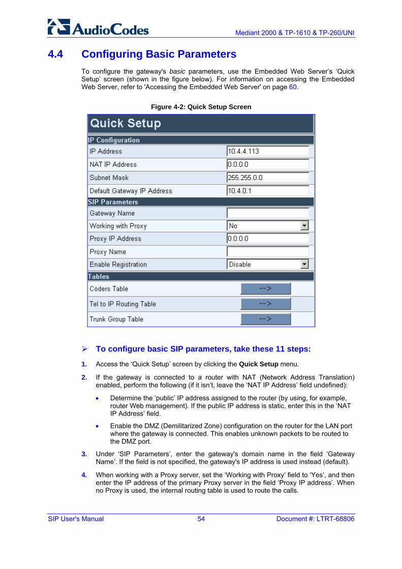
SIP User's Manual 54 Document #: LTRT-68806
Mediant 2000 & TP-1610 & TP-260/UNI
4.4 Configuring Basic Parameters To configure the gateway's basic parameters, use the Embedded Web Server’s ‘Quick Setup’ screen (shown in the figure below). For information on accessing the Embedded Web Server, refer to 'Accessing the Embedded Web Server' on page 60.
Figure 4-2: Quick Setup Screen
To configure basic SIP parameters, take these 11 steps:
1. Access the ‘Quick Setup’ screen by clicking the Quick Setup menu.
2. If the gateway is connected to a router with NAT (Network Address Translation) enabled, perform the following (if it isn’t, leave the ‘NAT IP Address’ field undefined):
• Determine the ‘public’ IP address assigned to the router (by using, for example, router Web management). If the public IP address is static, enter this in the ‘NAT IP Address’ field.
• Enable the DMZ (Demilitarized Zone) configuration on the router for the LAN port where the gateway is connected. This enables unknown packets to be routed to the DMZ port.
3. Under ‘SIP Parameters’, enter the gateway's domain name in the field ‘Gateway Name’. If the field is not specified, the gateway's IP address is used instead (default).
4. When working with a Proxy server, set the ‘Working with Proxy’ field to ‘Yes’, and then enter the IP address of the primary Proxy server in the field ‘Proxy IP address’. When no Proxy is used, the internal routing table is used to route the calls.

Version 5.2 55 September 2007
SIP User's Manual 4. Getting Started
5. Enter the Proxy name in the field ‘Proxy Name’. If Proxy name is used, it replaces the Proxy IP address in all SIP messages. This means that messages are still sent to the physical Proxy IP address, but the SIP URI contains the Proxy name instead.
6. Configure ‘Enable Registration’ to either one of the following:
• ‘Disable’ = the gateway doesn't register to a Proxy server/Registrar (default).
• ‘Enable’ = the gateway registers to a Proxy server/Registrar at power up and every ‘Registration Time’ seconds. For detailed information on the parameter ‘Registration Time’, refer to 'Proxy & Registration Parameters' on page 86.
7. To configure the Coders Table, click the arrow button next to ‘Coders Table’. For information on how to configure the Coders Table, refer to 'Coders' on page 96.
8. To configure the Tel to IP Routing Table, click the arrow button next to ‘Tel to IP Routing Table’. For information on how to configure the Tel to IP Routing Table, refer to 'Tel to IP Routing Table' on page 122.
9. To configure the E1/T1 B-channels, click the arrow button next to ‘Trunk Group Table’. For information on how to configure the Trunk Group Table, refer to Configuring the Trunk Group Table on page 138.
10. Click the Reset button, and then at the prompt, click OK; the gateway applies the changes and restarts.
11. After the gateway has reset, access the 'Trunk Settings' screen (Advanced Configuration > Trunk Settings), and select the gateway's E1/T1 protocol type and Framing method that best suits your system requirements. For information on how to configure the Trunk Settings, refer to 'Trunk Settings' on page 178.
You are now ready to start configuring the gateway. To prevent unauthorized access to the gateway, it's recommended that you change the default username and password used to access the Embedded Web Server. Refer to 'Configuring the Web User Accounts' on page 197 on how to change the username and password.
Tip: Once the gateway is configured correctly, back up your settings by saving a copy of the VoIP gateway configuration (ini file) to a directory on your PC. This saved file can be used to restore configuration settings at a later date. For information on backing up and restoring the gateway's configuration, refer to 'Restoring and Backing up Configuration' on page 258.

SIP User's Manual 56 Document #: LTRT-68806
Mediant 2000 & TP-1610 & TP-260/UNI
Reader's Notes

Version 5.2 57 September 2007
SIP User's Manual 5. Web-based Management
5 Web-based Management The gateway's Embedded Web Server is used for remote configuration of the gateway including loading of configuration files, as well as for online monitoring of the gateway. In addition, you can also remotely reset the gateway. The Embedded Web Server can be accessed from a standard Web browser such as Microsoft™ Internet Explorer and Netscape™ Navigator.
5.1 Computer Requirements To use the gateway's Embedded Web Server, the following is required:
A computer capable of running your Web browser.
A network connection to the gateway's Embedded Web Server.
One of the following compatible Web browsers:
• Microsoft™ Internet Explorer™ (version 6.0 or later)
• Netscape™ Navigator™ (version 7.2 or later)
• Mozilla Firefox® (version 1.5.0.10 or later)
Note: The Web browser must be javascript-enabled. If javascript is disabled, access to the Embedded Web Server is denied.
5.2 Protection and Security Mechanisms Access to the gateway's Embedded Web Server is controlled by the following protection and security mechanisms:
User accounts (refer to 'User Accounts' on page 58)
Read-only mode (refer to 'Limiting the Embedded Web Server to Read-Only Mode' on page 59)
Disabling access (refer to 'Disabling the Embedded Web Server' on page 59)
Limiting access to a predefined list of IP addresses (refer to 'Configuring the Web and Telnet Access List' on page 199)
Secured HTTP connection (HTTPS) (refer to the SIP Series Reference Manual)
Managed access using a RADIUS server (refer to the SIP Series Reference Manual)

SIP User's Manual 58 Document #: LTRT-68806
Mediant 2000 & TP-1610 & TP-260/UNI
5.2.1 User Accounts Up to five simultaneous users can be handled on gateway authentication via the Embedded Web Server. To prevent unauthorized access to the Embedded Web Server, two user accounts are available: primary and secondary. Each account is composed of three attributes: username, password, and access level. The username and password enable access to the Embedded Web Server itself; the access level determines the extent of the access (i.e., availability of screens and read / write privileges). Note that additional accounts can be defined using a RADIUS server (refer to the SIP Series Reference Manual).
The following table lists the available access levels and their privileges.
Table 5-1: Available Access Levels and their Privileges
Access Level Numeric Representation* Privileges
Security Administrator 200 Read / write privileges for all screens
Administrator 100 Read-only privilege for security-related screens and read / write privileges for the others
User Monitor 50 No access to security-related and file-loading screens and read-only access to the others
No Access 0 No access to any screen
* The numeric representation of the access level is used only to define accounts in a RADIUS server (the access level ranges from 1 to 255).
Each Web screen features two (hard-coded) minimum access levels, read and write. The read access level determines whether the screen can be viewed. The write access level determines whether the information in the screen can be modified. When a user tries to access a specific Web screen, the user's access level is compared with the access levels of the screen:
If the access level of the user is less than the screen's read access level, the screen cannot be viewed.
If the access level of the user is equal to or greater than the screen's read access level but less than the write access level, the screen is read only.
If the access level of the user is equal to or greater than the screen's write access level, the screen can be modified.
The default attributes for the two accounts are shown in the following table:
Table 5-2: Default Attributes for the Accounts
Account / Attribute Username (Case-Sensitive)
Password (Case-Sensitive)
Access Level
Primary Account Admin Admin Security Administrator*
Secondary Account User User User Monitor
* The access level of the primary account cannot be changed; all other account-attributes can be modified.

Version 5.2 59 September 2007
SIP User's Manual 5. Web-based Management
The first time a Web browser request is made, users are requested to provide their account's username and password to obtain access. If the Embedded Web Server is left idle for more than five minutes, the session expires and the user is required to re-enter username and password.
Tip: To access the Embedded Web Server with a different account, click the Log Off button and re-access with a new username and password.
For details on changing the account attributes, refer to 'Configuring the Web User Accounts' on page 197. Note that the password and username can be a maximum of 19 case-sensitive characters.
To reset the username and password of both accounts to their defaults, set the ini file parameter ResetWebPassword to 1.
5.2.2 Limiting the Embedded Web Server to Read-Only Mode Users can limit access to the Embedded Web Server to read-only mode by changing the ini file parameter DisableWebConfig to 1. In this mode, all Web screens, regardless of the access level used, are read-only and cannot be modified. In addition, the following screens cannot be accessed: 'Quick Setup', 'Web User Accounts', 'Maintenance Actions' and all file-loading screens.
Notes:
• Read-only policy can also be applied to selected users by setting the access level of the secondary account to 'User Monitor' (DisableWebConfig = 0) and distributing the primary and secondary accounts to users according to the organization's security policy.
• When DisableWebConfig is set to 1, read-only privileges are applied to all accounts regardless of their access level.
5.2.3 Disabling the Embedded Web Server Access to the Embedded Web Server can be disabled by setting the ini file parameter DisableWebTask to 1. By default, the access is enabled.

SIP User's Manual 60 Document #: LTRT-68806
Mediant 2000 & TP-1610 & TP-260/UNI
5.3 Accessing the Embedded Web Server You can access the gateway's Embedded Web Server by following the procedure below.
To access the Embedded Web Server, take these 4 steps:
1. Open a standard Web-browsing application (for a list of supported Web browsers, refer to 'Computer Requirements' on page 57).
2. In the Web browser's Uniform Resource Locator (URL) field, specify the gateway's IP address (e.g., http://10.1.10.10); the Embedded Web Server's 'Enter Network Password' screen appears, as shown in the figure below.
Figure 5-1: Enter Network Password Screen
3. In the 'User Name' and 'Password' fields, enter the username (default: 'Admin') and password (default: 'Admin'). Note that the username and password are case-sensitive.
4. Click the OK button; the Embedded Web Server is accessed, displaying the Home page (for a detailed description of the Home page, refer to Using the Home Page on page 260).
Note: If access to the gateway's Embedded Web Server is denied ("Unauthorized") due to Microsoft Internet Explorer security settings, perform the following troubleshooting procedures:
1. Delete all cookies in the Temporary Internet Files folder. If this does not resolve the problem, the security settings may need to be altered (continue with Step 2).
2. In Internet Explorer, navigate to Tools menu > Internet Options > Security tab > Custom Level, and then scroll down to the Logon options and select Prompt for username and password. Select the Advanced tab, and then scroll down until the HTTP 1.1 Settings are displayed and verify that Use HTTP 1.1 is selected.
3. Quit and start the Web browser again.

Version 5.2 61 September 2007
SIP User's Manual 5. Web-based Management
5.4 Getting Acquainted with the Web Interface The figure below displays the general layout of the interface of the Embedded Web Server.
The Embedded Web Server features the following components:
Title bar: contains three configurable elements: corporate logo, a background image, and the product's name. For information on how to modify these elements, refer to 'Customizing the Web Interface' on page 65.
Main menu bar: contains the main menus (refer to 'Main Menu Bar' on page 62).
Submenu bar: contains submenus pertaining to the selected main menu (from the Main menu bar). Each submenu provides a list of drop-down options that access configuration screens.
Main action frame: main area of the Embedded Web Server in which configuration screens are displayed.
Home icon: opens the Home page screen used mainly for monitoring the gateway (refer to 'Using the Home Page' on page 260).
Corporate logo: AudioCodes' corporate logo. For information on how to remove this logo, refer to 'Customizing the Web Interface' on page 65.
Search engine: used for searching ini file parameters that have corresponding Embedded Web Server parameters (refer to 'Searching for Configuration Parameters' on page 63).
Control Protocol: the gateway's control protocol (i.e., SIP).

SIP User's Manual 62 Document #: LTRT-68806
Mediant 2000 & TP-1610 & TP-260/UNI
5.4.1 Main Menu Bar The main menu bar of the Embedded Web Server provides the following menus:
Quick Setup: Accesses the 'Quick Setup' screen for quickly configuring the gateway's basic settings.For a full list of configurable parameters, directly access the Protocol Management and Advanced Configuration menus. An example of the Quick Setup configuration is described in 'Configuring the Basic Parameters' on page 54.
Protocol Management: used to configure the gateway's control protocol parameters and tables (refer to 'Protocol Management' on page 71).
Advanced Configuration: used to configure the gateway's advanced configuration parameters.
Status & Diagnostics: use to view Syslog messages, hardware / software product information, and to assess the gateway's statistics and IP connectivity information (refer to 'Status & Diagnostics' on page 226).
Software Update: used to load new software or configuration files to the gateway (refer to 'Software Update' on page 240).
Maintenance: used to remotely lock/unlock the gateway (refer to 'Locking and Unlocking the Gateway' on page 254), save configuration changes to the non-volatile flash memory (refer to 'Saving Configuration' on page 256), and reset the gateway (refer to 'Resetting the Gateway' on page 257).
5.4.2 Saving Changes To apply changes to the gateway's volatile memory (RAM), click the Submit button that appears in the screen in which you are working. Modifications to parameters with on-the-fly capabilities are immediately applied to the gateway; other parameters are updated only after a gateway reset.
Parameters saved to the volatile memory (i.e., not burned to flash memory), revert to their previous settings after a hardware reset (or if the gateway is powered down). However, when performing a software reset (i.e., using the Embedded Web Server or SNMP), you can also choose to save the parameter settings to the non-volatile memory (i.e., flash). To save the changes to flash, refer to 'Saving Configuration' on page 256.
Note: Parameters preceded by an exclamation mark (!) are not changeable on-the-fly and require that the device be reset.
5.4.3 Entering Phone Numbers in Various Tables Phone numbers or prefixes entered into various tables on the gateway such as the Tel to IP routing table, must be entered without any formatting characters. For example, if you wish to enter the phone number 555-1212, it must be entered as 5551212 without the hyphen (-). If the hyphen is entered, the entry is not valid. The hyphen character is used in number entry only, as part of a range definition. For example, the entry [20-29] means 'all numbers in the range 20 to 29.

Version 5.2 63 September 2007
SIP User's Manual 5. Web-based Management
5.4.4 Searching for Configuration Parameters The Embedded Web Server provides a search engine that allows you to search any ini file parameter that is configurable by the Web server. The Search button, located near the bottom of the Main menu bar is used to perform parameter searches.
You can search for a specific parameter (e.g., "EnableIPSec") or a sub-string of that parameter (e.g., "sec"). If you search for a sub-string, the Embedded Web Server lists all parameters that contain the searched sub-string in their parameter names.
To search for ini file parameters configurable in the Embedded Web Server, take these 3 steps:
1. In the Search Engine field, enter the parameter name or sub-string of the parameter name.
2. Click Search. The Searched Result screen appears, listing all searched parameter results, as shown in the example below:
Figure 5-2: Searched Result Screen
Each searched result displays the following:
• Parameter name (hyperlinked to its location in the Embedded Web Server)
• Brief description of the parameter
• Hyperlink in green displaying the URL path to its location in the Embedded Web Server location

SIP User's Manual 64 Document #: LTRT-68806
Mediant 2000 & TP-1610 & TP-260/UNI
3. In the searched result list, click the required parameter to open the screen in which the parameter appears; the searched parameter is highlighted in green in the screen for easy identification, as shown in the figure below.
Figure 5-3: Searched Parameter Highlighted in Screen
Note: If the searched parameter is not located, the "No Matches Found For This String" message is displayed.
Tip: When moving your curser over a parameter name (or table) for more than a second, a short description of the parameter is briefly displayed.

Version 5.2 65 September 2007
SIP User's Manual 5. Web-based Management
5.4.5 Customizing the Web Interface You can customize the gateway's Embedded Web Server interface to suit your specific corporate logo and product naming conventions. The following Web interface elements can be customized:
Main corporate logo displayed on the title bar (refer to 'Replacing the Main Corporate Logo' on page 65)
Background image displayed on the title bar (refer to 'Replacing the Background Image File' on page 68)
Product’s name displayed on the title bar (refer to 'Customizing the Product Name' on page 69)
Login welcome message (refer to 'Creating a Login Welcome Message' on page 70)
The figure below displays an example of the default title bar (i.e., of AudioCodes) and below it, a customized one:
Figure 5-4: Customized Web Interface Title Bar
Figure 5-5: Customized Web Interface Title Bar
5.4.5.1 Replacing the Main Corporate Logo
The main corporate logo can be replaced either with a different logo image file (refer to 'Replacing the Main Corporate Logo with an Image File' on page 66) or with a text string (refer to 'Replacing the Main Corporate Logo with a Text String' on page 67).
Notes:
• When the main corporation logo is replaced, AudioCodes’ logo on the left bar (refer to 'Getting Acquainted with the Web Interface' on page 61) and in the Software Upgrade Wizard (refer to 'Software Upgrade Wizard' on page 240) disappear.
• The Web browser’s title bar is automatically updated with the string assigned to the WebLogoText parameter when AudioCodes’ default logo is not used.

SIP User's Manual 66 Document #: LTRT-68806
Mediant 2000 & TP-1610 & TP-260/UNI
5.4.5.1.1 Replacing the Main Corporate Logo with an Image File
You can replace the logo in the Web interface's title bar using either the Embedded Web Server or the ini file.
To replace the default logo with your own corporate image via the Embedded Web Server, take these 7 steps:
1. Access the gateway's Embedded Web Server (refer to 'Accessing the Embedded Web Server' on page 60).
2. In the URL field, append the case-sensitive suffix ‘AdminPage’ to the IP address (e.g., http://10.1.229.17/AdminPage).
3. Click Image Load to Device; the Image Download screen is displayed, as shown in the figure below.
Figure 5-6: Image Download Screen
4. Click the Browse button in the 'Send Logo Image File from your computer to the Device' box. Navigate to the folder that contains the logo image file you want to load.
5. Click the Send File button; the file is sent to the device. When loading is complete, the screen is automatically refreshed and the new logo image is displayed.
6. If you want to modify the width of the logo (the default width is 339 pixels), in the 'Logo Width' field, enter the new width (in pixels) and then click the Set Logo Width button.
7. To save the image to flash memory, refer to 'Saving Configuration' on page 256.
The new logo appears on all Embedded Web Server interface pages.
Note: Use a gif, jpg or jpeg file for the logo image. It is important that the image file has a fixed height of 59 pixels (the width can be configured up to a maximum of 339 pixels). The size of the image files (logo and background) is limited each to 64 Kbytes.
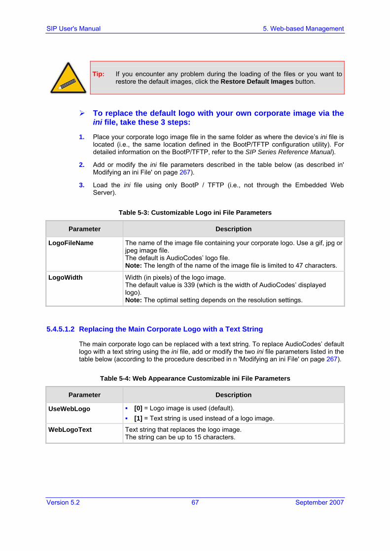
Version 5.2 67 September 2007
SIP User's Manual 5. Web-based Management
Tip: If you encounter any problem during the loading of the files or you want to restore the default images, click the Restore Default Images button.
To replace the default logo with your own corporate image via the ini file, take these 3 steps:
1. Place your corporate logo image file in the same folder as where the device’s ini file is located (i.e., the same location defined in the BootP/TFTP configuration utility). For detailed information on the BootP/TFTP, refer to the SIP Series Reference Manual).
2. Add or modify the ini file parameters described in the table below (as described in' Modifying an ini File' on page 267).
3. Load the ini file using only BootP / TFTP (i.e., not through the Embedded Web Server).
Table 5-3: Customizable Logo ini File Parameters
Parameter Description
LogoFileName The name of the image file containing your corporate logo. Use a gif, jpg or jpeg image file. The default is AudioCodes’ logo file. Note: The length of the name of the image file is limited to 47 characters.
LogoWidth Width (in pixels) of the logo image. The default value is 339 (which is the width of AudioCodes’ displayed logo). Note: The optimal setting depends on the resolution settings.
5.4.5.1.2 Replacing the Main Corporate Logo with a Text String
The main corporate logo can be replaced with a text string. To replace AudioCodes’ default logo with a text string using the ini file, add or modify the two ini file parameters listed in the table below (according to the procedure described in n 'Modifying an ini File' on page 267).
Table 5-4: Web Appearance Customizable ini File Parameters
Parameter Description
UseWebLogo [0] = Logo image is used (default). [1] = Text string is used instead of a logo image.
WebLogoText Text string that replaces the logo image. The string can be up to 15 characters.

SIP User's Manual 68 Document #: LTRT-68806
Mediant 2000 & TP-1610 & TP-260/UNI
5.4.5.2 Replacing the Background Image File
The background image file is duplicated across the width of the screen. The number of times the image is duplicated depends on the width of the background image and screen resolution. When choosing your background image, keep this in mind. The background image file can be replaced using either the Embedded Web Server or the ini file.
Note: Use a gif, jpg or jpeg file for the background image. It is important that the image file has a fixed height of 59 pixels. The size of the image files (logo and background) is limited each to 64 Kbytes.
To replace the background image using the Embedded Web Server, take these 6 steps:
1. Access the gateway's Embedded Web Server (refer to 'Accessing the Embedded Web Server' on page 60).
2. In the Web browser's URL field, append the case-sensitive suffix ‘AdminPage’ to the IP address (e.g., http://10.1.229.17/AdminPage).
3. Click the Image Load to Device; the 'Image Download' screen is displayed (shown in' Replacing the Main Corporate Logo with an Image File' on page 66).
4. Click the Browse button in the 'Send Background Image File from your computer to box', and then navigate to the folder that contains the background image file you want to load.
5. Click the Send File button; the file is sent to the device. When loading is complete, the screen is automatically refreshed and the new background image is displayed.
6. To save the image to flash memory, refer to 'Saving Configuration' on page 256.
The new background appears on all Embedded Web Server interface pages.
Tips:
• If you encounter any problem during the loading of the files or you want to restore the default images, click the Restore Default Images button.
• When replacing both the background image and the logo image, first load the logo image followed by the background image.

Version 5.2 69 September 2007
SIP User's Manual 5. Web-based Management
To replace the background image via the ini file, take these 3 steps:
1. Place your background image file in the same folder as where the device’s ini file is located (i.e., the same location defined in the BootP/TFTP configuration utility). For detailed information on the BootP/TFTP, refer to the SIP Series Reference Manual).
2. Add or modify the ini file parameters listed in the table below (according to the procedure described in 'Modifying an ini File' on page 267).
3. Load the ini file using only BootP / TFTP (i.e., not through the Embedded Web Server).
Table 5-5: Customizable Logo ini File Parameters
Parameter Description
BkgImageFileName The name (and path) of the file containing the new background. Use a gif, jpg or jpeg image file. The default is AudioCodes background file. Note: The length of the name of the image file is limited to 47 characters.
5.4.5.3 Customizing the Product Name
To replace AudioCodes’ default product name with a text string, add or modify the two ini file parameters listed in the table below (according to the procedure described in' Modifying an ini File' on page 267).
Table 5-6: Web Appearance Customizable ini File Parameters
Parameter Description
UseProductName [0] = Don’t change the product name (default). [1] = Enable product name change.
UserProductName Text string that replaces the product name. The default is ‘Mediant 2000’. The string can be up to 29 characters.

SIP User's Manual 70 Document #: LTRT-68806
Mediant 2000 & TP-1610 & TP-260/UNI
5.4.5.4 Creating a Login Welcome Message
You can create a Welcome message box (alert message) that appears (see figure below for an example) after each successful login to the gateway's Embedded Web Server. The ini file parameter table WelcomeMessage allows you to create the Welcome message. Up to 20 lines of character strings can be defined for the message. If this parameter is not configured, no Welcome message box is displayed after login.
Figure 5-7: User-Defined Web Welcome Message after Login
Table 5-7: User-Defined Welcome Message ini File Parameter
Parameter Description
WelcomeMessage Configures the Welcome message that appears after a Embedded Web Server login. The format of this ini file parameter table is: [WelcomeMessage] FORMAT WelcomeMessage_Index = WelcomeMessage_Text WelcomeMessage 1 = "..." ; WelcomeMessage 2 = "..." ; WelcomeMessage 3 = "..." ; [\WelcomeMessage]
For Example: [WelcomeMessage ] FORMAT WelcomeMessage_Index = WelcomeMessage_Text WelcomeMessage 1 = "**********************************" ; WelcomeMessage 2 = "********* This is a Welcome message ***" ; WelcomeMessage 3 = "**********************************" ; [\WelcomeMessage]
Note: Each index represents a line of text in the Welcome message box. Up to 20 indexes can be defined.

Version 5.2 71 September 2007
SIP User's Manual 5. Web-based Management
5.5 Protocol Management The Protocol Management menu is used to configure the gateway's SIP parameters and tables.
Note: Throughout this section, parameters enclosed in square brackets ([...]) depict the ini file parameters that correspond to the Embedded Web Server parameters. For configuration using the ini file, refer to 'ini File Configuration' on page 267.
5.5.1 Protocol Definition Parameters The Protocol Definition submenu is used to configure the following SIP protocol parameters:
General (refer to 'General Parameters' on page 72)
Proxy & Registration (refer to 'Proxy & Registration Parameters' on page 86)
Coders (refer to 'Coders' on page 96)
DTMF & Dialing (refer to 'DTMF & Dialing Parameters' on page 99)

SIP User's Manual 72 Document #: LTRT-68806
Mediant 2000 & TP-1610 & TP-260/UNI
5.5.1.1 General Parameters
The General Parameters option is used to configure general SIP parameters.
To configure the general SIP protocol parameters, take these 4 steps:
1. Open the 'General Parameters' screen (Protocol Management menu > Protocol Definition submenu > General Parameters option).
Figure 5-8: General Parameters (Protocol Definition Submenu)

Version 5.2 73 September 2007
SIP User's Manual 5. Web-based Management
2. Configure the parameters according to the table below.
3. Click the Submit button to save your changes.
4. To save the changes to flash memory, refer to 'Saving Configuration' on page 256.
Table 5-8: General Parameters (Protocol Definition)
Parameter Description
PRACK Mode [PRACKMode]
PRACK mechanism mode for 1xx reliable responses. Valid options include: [0] Disable [1] Supported (default) [2] Required
Notes: The Supported and Required headers contain the '100rel'
parameter. The gateway sends PRACK message if 180/183 response
is received with '100rel' in the Supported or the Required headers.

SIP User's Manual 74 Document #: LTRT-68806
Mediant 2000 & TP-1610 & TP-260/UNI
Table 5-8: General Parameters (Protocol Definition)
Parameter Description
Channel Select Mode [ChannelSelectMode]
Port allocation algorithm for IP-to-Tel calls. You can select one of the following methods: [0] By Dest Phone Number = (default) Select the gateway
port according to the called number. [1] Cyclic Ascending = Select the next available channel
in an ascending cycle order. Always select the next higher channel number in the trunk group. When the gateway reaches the highest channel number in the trunkgroup, it selects the lowest channel number in the trunkgroup and then starts ascending again.
[2] Ascending = Select the lowest available channel. Always start at the lowest channel number in the trunk group and if that channel is not available, select the next higher channel.
[3] Cyclic Descending = Select the next available channel in descending cycle order. Always select the next lower channel number in the trunk group. When the gateway reaches the lowest channel number in the hunt group, it selects the highest channel number in the trunk group and then starts descending again.
[4] Descending = Select the highest available channel. Always start at the highest channel number in the trunk group and if that channel is not available, select the next lower channel.
[5] Dest Number + Cyclic Ascending = First select the gateway port according to the called number. If the called number isn't found, then select the next available channel in ascending cyclic order. Note that if the called number is found, but the port associated with this number is busy, the call is released.
[6] By Source Phone Number = Select the gateway port according to the calling number.
[7] Trunk Cyclic Ascending = Select the gateway port from the first channel of the next trunk (next to the trunk from which the previous channel was allocated.
Note: The internal numbers of the gateway's B-channels are defined by the TrunkGroup parameter.
Enable Early Media [EnableEarlyMedia]
If enabled, the gateway sends 183 Session Progress response with SDP (instead of 180 Ringing), allowing the media stream to be set up prior to the answering of the call. [0] Disable = Early Media is disabled (default). [1] Enable = Enables Early Media.
Sending a 183 response depends on the Progress Indicator. It is sent only if PI = 1 or PI = 8 is received in Proceeding or Alert PRI messages. For CAS gateways, see the ProgressIndicator2IP parameter.

Version 5.2 75 September 2007
SIP User's Manual 5. Web-based Management
Table 5-8: General Parameters (Protocol Definition)
Parameter Description
183 Message Behavior [SIP183Behavior]
Defines the ISDN message that is sent when 183 Session Progress message is received for IP-to-Tel calls. Valid options include: [0] Progress = Progress message (default). [1] Alert = Alert message.
When set to 1, the gateway sends an Alert message (after the receipt of a 183 response) instead of an ISDN Progress message.
Session-Expires Time [SIPSessionExpires]
Determines the timeout (in seconds) for keeping a Re-INVITEmessage alive within a SIP session. The SIP session is refreshed each time this timer expires. The SIP method used for session-timer updates is determined according to the parameter SessionExpiresMethod. The valid range is 1 to 86400 sec. The default is 0 (i.e., not activated).
Minimum Session-Expires [MINSE]
Defines the time (in seconds) that is used in the Min-SE header. This header defines the minimum time that the user agent supports for session refresh. The valid range is 10 to 100000. The default value is 90.
Session Expires Method [SessionExpiresMethod]
Defines the SIP method used for session-timer updates. Valid options include: [0] Re-Invite = Use Re-INVITE messages for session-
timer updates (default). [1] Update = Use UPDATE messages.
Notes: The gateway can receive session-timer refreshes using
both methods. The UPDATE message used for session-timer purposes is
excluded from the SDP body.
Asserted Identity Mode [AssertedIdMode]
[0] Disabled = None (default) [1] Adding PAsserted Identity [2] Adding PPreferred Identity
The Asserted ID mode defines the header that is used in the generated INVITE request. The header also depends on the calling Privacy: allowed or restricted. The P-asserted (or P-preferred) headers are used to present the originating party's Caller ID. The Caller ID is composed of a Calling Number and (optionally) a Calling Name. P-asserted (or P-preferred) headers are used together with the Privacy header. If Caller ID is restricted, the 'Privacy: id' is included. Otherwise for allowed Caller ID, the 'Privacy: none' is used. If Caller ID is restricted (received from PSTN), the From header is set to <[email protected]>.
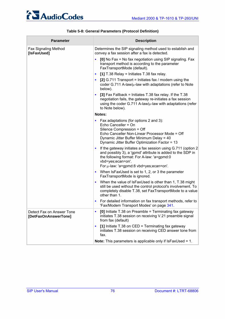
SIP User's Manual 76 Document #: LTRT-68806
Mediant 2000 & TP-1610 & TP-260/UNI
Table 5-8: General Parameters (Protocol Definition)
Parameter Description
Fax Signaling Method [IsFaxUsed]
Determines the SIP signaling method used to establish and convey a fax session after a fax is detected. [0] No Fax = No fax negotiation using SIP signaling. Fax
transport method is according to the parameter FaxTransportMode (default).
[1] T.38 Relay = Initiates T.38 fax relay. [2] G.711 Transport = Initiates fax / modem using the
coder G.711 A-law/µ-law with adaptations (refer to Note below).
[3] Fax Fallback = Initiates T.38 fax relay. If the T.38 negotiation fails, the gateway re-initiates a fax session using the coder G.711 A-law/µ-law with adaptations (refer to Note below).
Notes: Fax adaptations (for options 2 and 3):
Echo Canceller = On Silence Compression = Off Echo Canceller Non-Linear Processor Mode = Off Dynamic Jitter Buffer Minimum Delay = 40 Dynamic Jitter Buffer Optimization Factor = 13
If the gateway initiates a fax session using G.711 (option 2 and possibly 3), a 'gpmd' attribute is added to the SDP in the following format: For A-law: 'a=gpmd:0 vbd=yes;ecan=on'. For µ-law: 'a=gpmd:8 vbd=yes;ecan=on'.
When IsFaxUsed is set to 1, 2, or 3 the parameter FaxTransportMode is ignored.
When the value of IsFaxUsed is other than 1, T.38 might still be used without the control protocol's involvement. To completely disable T.38, set FaxTransportMode to a value other than 1.
For detailed information on fax transport methods, refer to 'Fax/Modem Transport Modes' on page 341.
Detect Fax on Answer Tone [DetFaxOnAnswerTone]
[0] Initiate T.38 on Preamble = Terminating fax gateway initiates T.38 session on receiving V.21 preamble signal from fax (default)
[1] Initiate T.38 on CED = Terminating fax gateway initiates T.38 session on receiving CED answer tone from fax.
Note: This parameters is applicable only if IsFaxUsed = 1.

Version 5.2 77 September 2007
SIP User's Manual 5. Web-based Management
Table 5-8: General Parameters (Protocol Definition)
Parameter Description
SIP Transport Type [SIPTransportType]
Determines the default transport layer used for outgoing SIP calls initiated by the gateway. Valid options include: [0] UDP (default) [1] TCP [2] TLS (SIPS)
Note: It's recommended to use TLS to communicate with a SIP Proxy and not for direct gateway-gateway communication.
SIP UDP Local Port [LocalSIPPort]
Local UDP port used to receive SIP messages. The valid range is 1 to 65534. The default value is 5060.
SIP TCP Local Port [TCPLocalSIPPort]
Local TCP port used to receive SIP messages. The default value is 5060.
SIP TLS Local Port [TLSLocalSIPPort]
Local TLS port used to receive SIP messages. The default value is 5061. Note: The value of TLSLocalSIPPort must be different to the value of TCPLocalSIPPort.
Enable SIPS [EnableSIPS]
Enables secured SIP (SIPS) connections over multiple hops. [0] Disable (default). [1] Enable.
When SIPTransportType = 2 (TLS) and EnableSIPS is disabled, TLS is used for the next network hop only. When SIPTransportType = 2 (TLS) or 1 (TCP) and EnableSIPS is enabled, TLS is used through the entire connection (over multiple hops). Note: If SIPS is enabled and SIPTransportType = UDP, the connection fails.
Enable TCP Connection Reuse [EnableTCPConnectionReuse]
Enables the reuse of the same TCP connection for all calls to the same destination. Valid options include: [0] Disable = Use a separate TCP connection for each call
(default) [1] Enable = Use the same TCP connection for all calls
TCP Timeout [SIPTCPTimeout]
Defines the Timer B and Timer F (as defined in RFC 3261) when the SIP Transport Type is TCP. The valid range is 0 to 40 sec. The default value is SIPT1Rtx * 64 msec.
SIP Destination Port [SIPDestinationPort]
SIP destination port for sending initial SIP requests. The valid range is 1 to 65534. The default port is 5060. Note: SIP responses are sent to the port specified in the Via header.
Use “user=phone” in SIP URL [IsUserPhone]
[0] No = 'user=phone' string isn't used in SIP URI. [1] Yes = 'user=phone' string is part of the SIP URI
(default).

SIP User's Manual 78 Document #: LTRT-68806
Mediant 2000 & TP-1610 & TP-260/UNI
Table 5-8: General Parameters (Protocol Definition)
Parameter Description
Use “user=phone” in From Header [IsUserPhoneInFrom]
[0] No = Doesn't use ';user=phone' string in From header (default).
[1] Yes = ';user=phone' string is part of the From header.
Use Tel URI for Asserted Identity [UseTelURIForAssertedID]
Determines the format of the URI in the P-Asserted and P-Preferred headers. [0] Disable = 'sip:' (default). [1] Enable = 'tel:'.
Tel to IP No Answer Timeout [IPAlertTimeout]
Defines the time (in seconds) the gateway waits for a 200 OK response from the called party (IP side) after sending an INVITE message. If the timer expires, the call is released. The valid range is 0 to 3600. The default value is 180.
Enable Remote Party ID [EnableRPIheader]
Enable Remote-Party-ID (RPI) headers for calling and called numbers for Tel IP calls. Valid options include: [0] Disable (default). [1] Enable = RPI headers are generated in SIP INVITE
messages for both called and calling numbers.
Add Number Plan and Type to RemoteParty ID Header [AddTON2RPI]
[0] No = TON/PLAN parameters aren't included in the RPID header.
[1] Yes = TON/PLAN parameters are included in the RPID header (default).
If RPID header is enabled (EnableRPIHeader = 1) and AddTON2RPI = 1, it's possible to configure the calling and called number type and number plan using the Number Manipulation tables for Tel�IP calls.

Version 5.2 79 September 2007
SIP User's Manual 5. Web-based Management
Table 5-8: General Parameters (Protocol Definition)
Parameter Description
Enable History-Info Header [EnableHistoryInfo]
Enables usage of the History-Info header. Valid options include: [0] Disable = Disable (default) [1] Enable = Enable
UAC Behavior: Initial request: The History-Info header is equal to the
Request URI. If a PSTN Redirect number is received, it is added as an additional History-Info header with an appropriate reason.
Upon receiving the final failure response, the gateway copies the History-Info as is, adds the reason of the failure response to the last entry, and concatenates a new destination to it (if an additional request is sent). The order of the reasons is as follows: - Q.850 Reason - SIP Reason - SIP Response code
Upon receiving the final (success or failure) response, the gateway searches for a Redirect reason in the History-Info (i.e., 3xx/4xx SIP Reason). If found, it is passed to ISDN, according to the following table:
SIP Reason Code ISDN Redirecting Reason 302 - Moved Temporarily Call Forward Universal (CFU)
408 - Request Timeout
480 - Temporarily Unavailable
Call Forward No Answer (CFNA)
486 - Busy Here
600 - Busy Everywhere
Call Forward Busy (CFB)
If history reason is a Q.850 reason, it is translated to the
SIP reason (according to the SIP-ISDN tables) and then to ISDN Redirect reason according to the table above.
UAS Behavior: History-Info is sent in the final response only. Upon receiving a request with History-Info, the UAS
checks the policy in the request. If 'session', 'header', or 'history' policy tag is found, the (final) response is sent without History-Info. Otherwise, it is copied from the request.

SIP User's Manual 80 Document #: LTRT-68806
Mediant 2000 & TP-1610 & TP-260/UNI
Table 5-8: General Parameters (Protocol Definition)
Parameter Description
Use Source Number as Display Name [UseSourceNumberAsDisplayName]
Applicable to Tel-to-IP calls. [0] No = The Tel Source Number is used as the IP Source
Number and the Tel Display Name is used as the IP Display Name (if Tel Display Name is received). If no Display Name is received from the Tel side, the IP Display Name remains empty (default).
[1] Yes = If a Tel Display Name is received, the Tel Source Number is used as the IP Source Number and the Tel Display Name is used as the IP Display Name. If no Display Name is received from the Tel side, the Tel Source Number is used as the IP Source Number and also as the IP Display Name.
[2] Overwrite = The Tel Source Number is used as the IP Source Number and also as the IP Display Name (even if the received Tel Display Name is not empty).
Use Display Name as Source Number [UseDisplayNameAsSourceNumber]
Applicable to IP-to-Tel calls. [0] No = The IP Source Number is used as the Tel Source
Number and the IP Display Name is used as the Tel Display Name (if IP Display Name is received). If no Display Name is received from IP, the Tel Display Name remains empty (default).
[1] Yes = If an IP Display Name is received, it is used as the Tel Source Number and also as the Tel Display Name, the Presentation is set to Allowed (0). If no Display Name is received from IP, the IP Source Number is used as the Tel Source Number and the Presentation is set to Restricted (1).
For example: When the following is received 'from: 100 <sip:[email protected]>', the outgoing Source Number and Display Name are set to '100' and the Presentation is set to Allowed (0). When the following is received 'from: <sip:[email protected]>', the outgoing Source Number is set to '100' and the Presentation is set to Restricted (1).

Version 5.2 81 September 2007
SIP User's Manual 5. Web-based Management
Table 5-8: General Parameters (Protocol Definition)
Parameter Description
Play Ringback Tone to IP [PlayRBTone2IP]
[0] Don't Play = Ringback tone isn't played to the IP side of the call (default).
[1] Play = Ringback tone is played to the IP side of the call after SIP 183 session progress response is sent.
If configured to 1 ('Play'), and if EnableEarlyMedia = 1, for IP-to-Tel calls the gateway may play a ringback tone to IP, according to the following: For CAS interfaces, the gateway opens a voice channel,
sends a 183+SDP response and plays a Ringback tone to IP.
For ISDN interfaces, if a Progress or an Alert message with PI (1 or 8) is received from the ISDN, the gateway opens a voice channel, sends a 183+SDP or 180+SDP response, but it doesn't play a Ringback tone to IP. If PI (1 or 8) is received from the ISDN, the gateway assumes that Ringback tone is played by the ISDN Switch. Otherwise, the fateway plays a Ringback tone to IP after receiving an Alert message from the ISDN. It sends a 180+SDP response, signaling to the originating party to open a voice channel to hear the played Ringback tone.
Notes: To enable the gateway to send a 183/180+SDP
responses, set EnableEarlyMedia to 1. If EnableDigitDelivery = 1, the gateway doesn't play a
Ringback tone to IP and doesn't send 183 or 180+SDP responses.
Play Ringback Tone to Tel [PlayRBTone2Tel]
Determines the method used to play Ringback tone to the Tel side. It applies to all trunks that are not configured by the parameter PlayRBTone2Trunk. Similar description as the parameter PlayRBTone2Trunk.
Use Tgrp Information [UseSIPTgrp]
[0] Disable = Tgrp parameter isn't used (default). [1] Send Only = The trunk group number is added as the
'tgrp' parameter to the Contact header of outgoing SIP messages. If a trunk group number is not associated with the call, the 'tgrp' parameter isn't included. If a 'tgrp' value is specified in incoming messages, it is ignored.
[2] Send and Receive = The functionality of outgoing SIP messages is identical to the functionality described in option (1). In addition, for incoming SIP messages, if the Request-URI includes a 'tgrp' parameter, the gateway routes the call according to that value (if possible). If the Contact header includes a 'tgrp' parameter, it is copied to the corresponding outgoing messages in that dialog.

SIP User's Manual 82 Document #: LTRT-68806
Mediant 2000 & TP-1610 & TP-260/UNI
Table 5-8: General Parameters (Protocol Definition)
Parameter Description
Enable GRUU [EnableGRUU]
Determines whether or not the Globally Routable User Agent URIs (GRUU) mechanism is used. Valid options include: [0] Disable = Disable (default) [1] Enable = Enable
The gateway obtains a GRUU by generating a normal REGISTER request. This request contains a Supported header field with the value “gruu”. The gateway includes a “+sip.instance” Contact header field parameter for each contact for which the GRUU is desired. This Contact parameter contains a globally unique ID that identifies the gateway instance.
The global unique id is as follows: If registration is per endpoint (AuthenticationMode=0), it is
the MAC address of the gateway concatenated with the phone number of the endpoint.
If the registration is per gateway (AuthenticationMode=1) it is only the MAC address.
When the “User Information” mechanism is used, the globally unique ID is the MAC address concatenated with the phone number of the endpoint (defined in the User-Info file).
If the Registrar/Proxy supports GRUU, the REGISTER responses contain the “gruu” parameter in each Contact header field. The Registrar/Proxy provides the same GRUU for the same AOR and instance-id in case of sending REGISTER again after expiration of the registration. The gateway places the GRUU in any header field which contains a URI. It uses the GRUU in the following messages: INVITE requests, 2xx responses to INVITE, SUBSCRIBE requests, 2xx responses to SUBSCRIBE, NOTIFY requests, REFER requests, and 2xx responses to REFER. Note: If the GRUU contains the "opaque" URI parameter, the gateway obtains the AOR for the user by stripping the parameter. The resulting URI is the AOR. For example: AOR: sip:[email protected] GRUU: sip:[email protected];opaque="kjh29x97us97d"
User-Agent Information [UserAgentDisplayInfo]
Defines the string that is used in the SIP request header 'User-Agent' and SIP response header 'Server'. If not configured, the default string 'AudioCodes product-name s/w-version' is used (e.g., User-Agent: Audiocodes-Sip-Gateway-Mediant 2000/v.4.80.004.008). When configured, the string 'UserAgentDisplayInfo s/w-version' is used (e.g., User-Agent: MyNewOEM/v.4.80.004.008). Note that the version number can't be modified. The maximum string length is 50 characters.

Version 5.2 83 September 2007
SIP User's Manual 5. Web-based Management
Table 5-8: General Parameters (Protocol Definition)
Parameter Description
SDP Session Owner [SIPSDPSessionOwner]
Determines the value of the Session Owner line (“o” field) in outgoing SDP bodies. The valid range is a string of up to 39 characters. The default value is 'AudiocodesGW'. For example: o=AudiocodesGW 1145023829 1145023705 IN IP4 10.33.4.126
Play Busy Tone to Tel [PlayBusyTone2ISDN]
Enables the ISDN gateway to play a Busy or a Reorder tone to the PSTN after a call is released. [0] Don't Play = Immediately sends an ISDN Disconnect
message (default). [1] Play when Disconnecting = Sends an ISDN Disconnect
message with PI=8 and plays a Busy or a Reorder tone to the PSTN (depending on the release cause).
[2] Play before Disconnect = Delays the sending of an ISDN Disconnect message for TimeForReorderTone seconds and plays a Busy or a Reorder tone to the PSTN. Applicable only if the call is released from the IP before it reaches the Connect state. Otherwise, the Disconnect message is sent immediately and no tones are played.
Subject [SIPSubject]
Defines the value of the Subject header in outgoing INVITE messages. If not specified, the Subject header isn't included (default). The maximum length of the subject is limited to 50 characters.
Multiple Packetization Time Format [MultiPtimeFormat]
Determines whether the 'mptime' attribute is included in the outgoing SDP. Valid options include: [0] None = Disabled (default) [1] PacketCable = includes the mptime attribute in the
outgoing SDP -- PacketCable-defined format The 'mptime' attribute enables the gateway to define a separate Packetization period for each negotiated coder in the SDP. The 'mptime' attribute is only included if this parameter is enabled, even if the remote side includes it in the SDP offer.Upon reception, each coder receives its 'ptime' value in the following precedence: From 'mptime' attribute. From 'ptime' attribute. Default value.
Enable Reason Header [EnableReasonHeader]
Enables / disables the usage of the SIP Reason header. [0] Disable. [1] Enable (default).

SIP User's Manual 84 Document #: LTRT-68806
Mediant 2000 & TP-1610 & TP-260/UNI
Table 5-8: General Parameters (Protocol Definition)
Parameter Description
Enable Semi-Attended Transfer [EnableSemiAttendedTransfer]
Determines the gateway behavior when Transfer is initiated while still in Alerting state. Valid options include: [0] Disable = Send REFER with Replaces (default). [1] Enable = Send CANCEL, and after a 487 response is
received, send REFER without Replaces.
3xx Behavior [3xxBehavior]
Determines the gateway's behavior when a 3xx response is received for an outgoing INVITE request. The gateway can either use the same call identifiers (CallID, branch, to and from tags) or change them in the new initiated INVITE. [0] Forward = Use different call identifiers for a redirected
INVITE message (default). [1] Redirect = Use the same call identifiers.
Enable P-Charging Vector [EnablePChargingVector]
Enables the addition of a P-Charging-Vector header to all outgoing INVITE messages. Valid options include: [0] Disable = Disable (default) [1] Enable = Enable
Enable VoiceMail URI [EnableVMURI]
Enables or disables the interworking of target and cause for redirection from Tel to IP and vice versa, according to RFC 4468.
Valid options include: [0] Disable = Disable (default). [1] Enable = Enable
Upon receipt of a SETUP request with redirect values, the gateway maps the Redirect phone number to the target parameter, and the Redirect number reason to the cause parameter in the Request-URI.
Redirecting Reason >> Value
Unknown >> 404
User busy >> 486
No reply >> 408
Deflection >> 487/480
Unconditional >> 302
Others >> 302
If the gateway receives a Request-URI that includes a target and cause parameters, the target is mapped to the redirect phone number and the cause is mapped to redirect number reason.

Version 5.2 85 September 2007
SIP User's Manual 5. Web-based Management
Table 5-8: General Parameters (Protocol Definition)
Parameter Description
Retransmission Parameters
SIP T1 Retransmission Timer [msec] [SipT1Rtx]
The time interval (in msec) between the first transmission of a SIP message and the first retransmission of the same message. The default is 500. Note: The time interval between subsequent retransmissions of the same SIP message starts with SipT1Rtx and is multiplied by two until SipT2Rtx. For example (assuming that SipT1Rtx = 500 and SipT2Rtx = 4000): The first retransmission is sent after 500 msec. The second retransmission is sent after 1000 (2*500)
msec. The third retransmission is sent after 2000 (2*1000) msec. The fourth retransmission and subsequent
retransmissions until SIPMaxRtx are sent after 4000 (2*2000) msec.
SIP T2 Retransmission Timer [msec] [SipT2Rtx]
The maximum interval (in msec) between retransmissions of SIP messages. The default is 4000. Note: The time interval between subsequent retransmissions of the same SIP message starts with SipT1Rtx and is multiplied by two until SipT2Rtx.
SIP Maximum RTX [SIPMaxRtx]
Number of UDP transmissions (first transmission plus retransmissions) of SIP messages. The range is 1 to 30. The default value is 7.

SIP User's Manual 86 Document #: LTRT-68806
Mediant 2000 & TP-1610 & TP-260/UNI
5.5.1.2 Proxy & Registration Parameters
The Proxy & Registration option is used to configure parameters that are associated with Proxy and Registration.
To configure the Proxy & Registration parameters, take these 4 steps:
1. Open the 'Proxy & Registration' parameters screen (Protocol Management menu > Protocol Definition submenu > Proxy & Registration option).
Figure 5-9: Proxy & Registration Screen

Version 5.2 87 September 2007
SIP User's Manual 5. Web-based Management
2. Configure the Proxy and Registration parameters according to the following table.
3. Click the Submit button to save your changes, or click the Register or Un-Register buttons to save your changes and register / unregister to a Proxy / Registrar.
4. To save the changes to flash memory, refer to 'Saving Configuration' on page 256.
Table 5-9: Proxy & Registration Parameters
Parameter Description
Enable Proxy [IsProxyUsed]
Enables the use of a Proxy server. [0] Don't Use Proxy = Proxy isn't used, the internal routing table is used
instead (default). [1] Use Proxy = Proxy is used.
If you are using a Proxy server, enter the IP address of the primary Proxy server in the 'Proxy IP address' field. If you are not using a Proxy server, you must configure the Tel to IP Routing table on the gateway (described in 'Tel to IP Routing Table' on page 122).
Proxy parameters (these parameter fields only appear if 'Enable Proxy' is enable)
Proxy Name [ProxyName]
Defines the Home Proxy Domain Name. If specified, the Proxy Name is used as Request-URI in REGISTER, INVITE and other SIP messages. If not specified, the Proxy IP address is used instead.
Proxy IP Address [ProxyIP]
IP address (and optionally port number) of the primary Proxy server you are using. Enter the IP address as FQDN or in dotted decimal notation (e.g., 201.10.8.1). You can also specify the selected port in the format: <IP Address>:<port>. If you enable Proxy Redundancy (by setting EnableProxyKeepAlive = 1 or 2), the gateway can work with up to 15 Proxy servers. If there is no response from the primary Proxy, the gateway tries to communicate with the redundant Proxies. When a redundant Proxy is found, the gateway either continues working with it until the next failure occurs or reverts to the primary Proxy (refer to the 'Redundancy Mode' parameter). If none of the Proxy servers respond, the gateway goes over the list again. The gateway also provides real time switching (hotswap mode), between the primary and redundant proxies (IsProxyHotSwap = 1). If the first Proxy doesn't respond to INVITE message, the same INVITE message is immediately sent to the next Proxy. The same logic applies to REGISTER messages (in case that RegistrarIP is not defined). Notes: This parameter is applicable only if you select 'Use Proxy' in the 'Enable
Proxy' field. If EnableProxyKeepAlive = 1 or 2, the gateway monitors the connection
with the Proxies by using keep-alive messages (OPTIONS or REGISTER).
To use Proxy Redundancy, you must specify one or more redundant Proxies using multiple 'ProxyIP= <IP address>' definitions.
When port number is specified (e.g., domain.com:5080), DNS NAPTR/SRV queries aren't performed, even if ProxyDNSQueryType is set to 1 or 2.

SIP User's Manual 88 Document #: LTRT-68806
Mediant 2000 & TP-1610 & TP-260/UNI
Table 5-9: Proxy & Registration Parameters
Parameter Description
First Redundant Proxy IP Address [ProxyIP]
IP addresses of the first redundant Proxy you are using. Enter the IP address as FQDN or in dotted decimal notation (e.g., 192.10.1.255). You can also specify the selected port in the format <IP Address>:<port>. Notes: This parameter is available only if you select 'Use Proxy' in the 'Enable
Proxy' field. When port number is specified, DNS NAPTR/SRV queries aren't
performed, even if ProxyDNSQueryType is set to 1 or 2. For the ini file, the IP address of the first redundant Proxy are defined by
the second repetition of the ini file parameter ProxyIP.
Second Redundant Proxy IP Address [ProxyIP]
IP addresses of the second redundant Proxy you are using. Enter the IP address as FQDN or in dotted decimal notation (e.g., 192.10.1.255). You can also specify the selected port in the format <IP Address>:<port>. Notes: This parameter is available only if you select 'Use Proxy' in the 'Enable
Proxy' field. When port number is specified, DNS NAPTR/SRV queries aren't
performed, even if ProxyDNSQueryType is set to 1 or 2. For the ini file, the IP address of the second redundant Proxy is defined
by the third repetition of the ini file parameter ProxyIP.
Third Redundant Proxy IP Address [ProxyIP]
IP addresses of the third redundant Proxy you are using. Enter the IP address as FQDN or in dotted decimal notation (e.g., 192.10.1.255). You can also specify the selected port in the format <IP Address>:<port>. Notes: This parameter is available only if you select 'Use Proxy' in the 'Enable
Proxy' field. When port number is specified, DNS NAPTR/SRV queries aren't
performed, even if ProxyDNSQueryType is set to 1 or 2. For the ini file, the IP addresses of the third redundant Proxy is defined
by the fourth repetition of the ini file parameter ProxyIP.
Redundancy Mode [ProxyRedundancyMode]
[0] Parking = gateway continues working with the last active Proxy until the next failure (default).
[1] Homing = gateway always tries to work with the primary Proxy server (switches back to the main Proxy whenever it's available).
Note: To use ProxyRedundancyMode, enable Keep-alive with Proxy option (EnableProxyKeepAlive = 1 or 2).

Version 5.2 89 September 2007
SIP User's Manual 5. Web-based Management
Table 5-9: Proxy & Registration Parameters
Parameter Description
Proxy Load Balancing Method [ProxyLoadBalancingMethod]
Enables the usage of the Proxy Load Balancing mechanism. [0] Disable = Load Balancing is disabled (default). [1] Round Robin = Round Robin. [2] Random Weights = Random Weights.
When Round Robin (1) algorithm is used, a list of all possible Proxy IP addresses is compiled. This list includes all entries in the ProxyIP table after necessary DNS resolutions (including NAPTR and SRV, if configured). This list can handle up to 15 entries. After this list is compiled, the Proxy Keep-Alive mechanism (according to EnableProxyKeepAlive and ProxyKeepAliveTime) is used to mark each entry as Offline or Online. The balancing is only performed on Proxy servers that are marked as Online. All outgoing messages are equally distributed across the Proxy IP list. REGISTER messages are also distributed unless a RegistrarIP is configured. The Proxy IP list is refreshed according to ProxyIPListRefreshTime. If a change in the order of the entries in the list occurs, all load statistics are erased and balancing starts over again. When Random Weights (2) algorithm is used, the outgoing requests are not distributed equally among the Proxies. The weights are received from the DNS server by using SRV records. The gateway sends the requests in such a fashion that each Proxy receives a percentage of the requests according to its assigned weight.Only single FQDN should be configured as a Proxy IP address. The Random Weights Load Balancing is not used in the following scenarios: The ProxyIP table includes more than one entry. The only Proxy defined is an IP address and not an FQDN. SRV usage is not enabled (DNSQueryType). The SRV response includes several records with a different Priority
value.
Proxy IP List Refresh Time [ProxyIPListRefreshTime]
Defines the time interval (in seconds) between refreshes of the Proxy IP list. This parameter is used only when ProxyLoadBalancingMethod = 1. The interval range is 5 to 2,000,000. The default interval is 60.

SIP User's Manual 90 Document #: LTRT-68806
Mediant 2000 & TP-1610 & TP-260/UNI
Table 5-9: Proxy & Registration Parameters
Parameter Description
Enable Proxy Keep Alive [EnableProxyKeepAlive]
Determines whether Keep-Alive with the Proxy is enabled or disabled. [0] Disable = Disable (default)\ [1] Using OPTIONS = Enable Keep alive with Proxy using OPTIONS [2] Using REGISTER = Enable Keep alive with Proxy using REGISTER
If EnableProxyKeepAlive = 1, SIP OPTIONS message is sent every ProxyKeepAliveTime. If EnableProxyKeepAlive = 2, SIP REGISTER message is sent every RegistrationTime. Any response from the Proxy, either success (200 OK) or failure (4xx response) is considered as if the Proxy is correctly communicating.
Notes: This parameter must be set to 1 (OPTIONS) when Proxy redundancy is
used. When EnableProxyKeepAlive = 2 (REGISTER), the homing redundancy
mode is disabled. When the active proxy doesn't respond to INVITE messages sent by the
gateway, the proxy is marked as offline. The behavior is similar to a Keep-Alive (OPTIONS or REGISTER) failure.
Proxy Keep Alive Time[ProxyKeepAliveTime]
Defines the Proxy keep-alive time interval (in seconds) between Keep-Alive messages. The default value is 60 seconds. Note: This parameter is applicable only if EnableProxyKeepAlive = 1 (OPTIONS). When EnableProxyKeepAlive = 2 (REGISTER), the time interval between Keep-Alive messages is determined by the parameter RegistrationTime.
Enable Fallback to Routing Table [IsFallbackUsed]
[0] Disable = gateway fallback is not used (default). [1] Enable = Internal Tel to IP Routing table is used when Proxy servers
are unavailable. When the gateway falls back to the internal Tel to IP Routing table, the gateway continues scanning for a Proxy. When the gateway finds an active Proxy, it switches from internal routing back to Proxy routing. Note: To enable the redundant Proxies mechanism set EnableProxyKeepAlive to 1 or 2.
Prefer Routing Table [PreferRouteTable]
Determines if the local Tel to IP routing table takes precedence over a Proxy for routing calls. [0] No = Only Proxy is used to route calls (default). [1] Yes = The gateway checks the 'Dest Phone Prefix' and/or 'Source
Phone Prefix' field in the 'Tel to IP Routing' table for a match with the outgoing call. Only if a match is not found, a Proxy is used.
Note: Applicable only if Proxy is not always used (AlwaysSendToProxy = 0, SendInviteToProxy = 0).

Version 5.2 91 September 2007
SIP User's Manual 5. Web-based Management
Table 5-9: Proxy & Registration Parameters
Parameter Description
Use Routing Table for Host Names and Profiles [AlwaysUseRouteTable]
Use the internal Tel to IP routing table to obtain the URI Host name and (optionally) an IP profile (per call), even if Proxy server is used. [0] Disable = Don't use (default). [1] Enable = Use.
Note: This domain name is used, instead of Proxy name or Proxy IP address, in the INVITE SIP URI.
Always Use Proxy [AlwaysSendToProxy]
[0] Disable = Use standard SIP routing rules (default). [1] Enable = All SIP messages and Responses are sent to Proxy server.
Note: Applicable only if Proxy server is used (i.e., IsProxyUsed = 1).
Send All INVITE to Proxy [SendInviteToProxy]
[0] No = INVITE messages, generated as a result of Transfer or Redirect, are sent directly to the URI (according to the Refer-To header in the REFER message or Contact header in 30x response) (default).
[1] Yes = All INVITE messages, including those generated as a result of Transfer or Redirect are sent to Proxy.
Note: Applicable only if Proxy server is used and AlwaysSendtoProxy = 0.
Enable Proxy Hot-Swap[IsProxyHotSwap]
Enable Proxy Hot-Swap redundancy mode. [0] Disable = Disabled (default). [1] Enable = Enabled.
If Hot Swap is enabled, SIP INVITE/REGISTER message is first sent to the primary Proxy/Registrar server. If there is no response from the primary Proxy/Registrar server for HotSwapRtx retransmissions, the INVITE/REGISTER message is resent to the next redundant Proxy/Registrar server.
Proxy / Registrar Registration parameters (the parameter fields appear only if 'Enable Registration' is enabled)
Enable Registration [IsRegisterNeeded]
Enables the gateway to register to Proxy / Registrar server. [0] Disable = gateway doesn't register to Proxy / Registrar (default). [1] Enable = gateway registers to Proxy / Registrar when the device is
powered up and every RegistrationTime seconds. Note: The gateway sends a REGISTER request for each channel or for the entire gateway (according to the AuthenticationMode parameter).
Registrar Name [RegistrarName]
Registrar Domain Name. If specified, the name is used as Request-URI in REGISTER messages. If it isn't specified (default), the Registrar IP address or Proxy name or Proxy IP address is used instead.

SIP User's Manual 92 Document #: LTRT-68806
Mediant 2000 & TP-1610 & TP-260/UNI
Table 5-9: Proxy & Registration Parameters
Parameter Description
Registrar IP Address [RegistrarIP]
IP address (numerical or FQDN) and optionally port number of Registrar server. Enter the IP address in dotted format notation, for example, 201.10.8.1:<5080>. Notes: If not specified, the REGISTER request is sent to the primary Proxy
server (refer to 'Proxy IP address' parameter). When port number is specified, DNS NAPTR/SRV queries aren't
performed, even if DNSQueryType is set to 1 or 2. If the RegistrarIP is set to an FQDN and is resolved to multiple
addresses, the gateway also provides real-time switching (hotswap mode) between different Registrar IP addresses (IsProxyHotSwap = 1). If the first Registrar doesn't respond to the REGISTER message, the same REGISTER message is immediately sent to the next Registrar. EnableProxyKeepAlive must be set to 0 in order for this logic to apply.
Registration Time [RegistrationTime]
Defines the time (in seconds) for which registration to a Proxy server is valid. The value is used in the header 'Expires'. In addition, this parameter defines the time interval between Keep-Alive messages when EnableProxyKeepAlive = 2 (REGISTER). Typically, a value of 3600 should be assigned for one hour registration. The gateway resumes registration according to the parameter RegistrationTimeDivider. The default value is 180. The valid range is 10 to 2000000.
Re-registration Timing [%] [RegistrationTimeDivider]
Defines the re-registration timing (in percentage). The timing is a percentage of the re-register timing set by the Registration server. The valid range is 50 to 100. The default value is 50. For example: If RegistrationTimeDivider = 70 (%) and Registration Expires time = 3600, the gateway resends its registration request after 3600 x 70% = 2520 sec. Note: This parameter may be overriden if RegistrationTimeThreshold is greater than 0 (see description of RegistrationTimeThreshold).
Registration Retry Time[RegistrationRetryTime]
Defines the time period (in seconds) after which a Registration request is resent if registration fails with 4xx, or there is no response from the Proxy/Registrar. The default is 30 seconds. The range is 10 to 3600.
Registration Time Threshold [RegistrationTimeThreshold]
Defines (in seconds) a threshold for re-registration timing. If RegistrationTimeThreshold is greater than 0, but lower than the computed re-registration timing (according to RegistrationTimeDivider), the re-registration timing is set to: the timing set by the Registration server in the Expires header minus RegistrationTimeThreshold. The valid range is 0 to 2,000,000 seconds. The default value is 0 seconds.
Re-register On INVITE Failure [RegisterOnInviteFailure]
Enables immediate re-registration if a failure response is received for an INVITE request sent by the gateway. Valid options include: [0] Disable = Disabled (default) [1] Enable = Enabled

Version 5.2 93 September 2007
SIP User's Manual 5. Web-based Management
Table 5-9: Proxy & Registration Parameters
Parameter Description
Miscellaneous parameters
Gateway Name [SIPGatewayName]
Assigns a name to the gateway (e.g., 'gateway1.com'). Ensure that the name you choose is the one that the Proxy is configured with to identify your gateway. Note: If specified, the gateway name is used as the host part of the SIP URI in the From header. If not specified, the gateway IP address is used instead (default).
Gateway Registration Name [GWRegistrationName]
Defines the user name that is used in the From and To headers of REGISTER messages. If GWRegistrationName isn't specified (default), the 'Username' parameter is used instead. Note: This parameter is applicable only to a single registration per gateway (AuthenticationMode = 1). When the gateway registers each channel separately (AuthenticationMode = 0), the user name is set to the channel's phone number.
DNS Query Type [DNSQueryType]
Enables the use of DNS Naming Authority Pointer (NAPTR) and Service Record (SRV) queries to resolve Proxy and Registrar servers and to resolve all domain names that appear in the Contact and Record-Route headers.
Valid options include: [0] A-Record = A-Record (default) [1] SRV = SRV [2] NAPTR = NAPTR
If set to A-Record [0], no NAPTR or SRV queries are performed.
If set to SRV [1], and the Proxy / Registrar IP address parameter, the domain name in the Contact / Record-Route headers, or the IP address defined in the Routing tables contains a domain name without port definition, an SRV query is performed. The gateway uses the first host name received from the SRV query. The gateway then performs a DNS A-record query for the host name to locate an IP address.
If set to NAPTR [2], an NAPTR query is performed. If it is successful, an SRV query is sent according to the information received in the NAPTR response. If the NAPTR query fails, an SRV query is performed according to the configured transport type.
If the Proxy / Registrar IP address parameter, the domain name in the Contact / Record-Route headers, or the IP address defined in the Routing tables contains a domain name with port definition, the gateway performs a regular DNS A-record query. Note: To enable NAPTR/SRV queries for Proxy servers only, use the parameter ProxyDNSQueryType.

SIP User's Manual 94 Document #: LTRT-68806
Mediant 2000 & TP-1610 & TP-260/UNI
Table 5-9: Proxy & Registration Parameters
Parameter Description
Proxy DNS Query Type[ProxyDNSQueryType]
Enables the use of DNS Naming Authority Pointer (NAPTR) and Service Record (SRV) queries to discover Proxy servers.
Valid options include: [0] A-Record = A-Record (default) [1] SRV = SRV [2] NAPTR = NAPTR
If set to A-Record [0], no NAPTR or SRV queries are performed.
If set to SRV [1] and the Proxy IP address parameter contains a domain name without port definition (e.g., ProxyIP = domain.com), an SRV query is performed. The SRV query returns up to four Proxy host names and their weights. The gateway then performs DNS A-record queries for each Proxy host name (according to the received weights) to locate up to four Proxy IP addresses. Therefore, if the first SRV query returns two domain names, and the A-record queries return two IP addresses each, no more searches are performed. If set to NAPTR [2], an NAPTR query is performed. If it is successful, an SRV query is sent according to the information received in the NAPTR response. If the NAPTR query fails, an SRV query is performed according to the configured transport type. If the Proxy IP address parameter contains a domain name with port definition (e.g., ProxyIP = domain.com:5080), the gateway performs a regular DNS A-record query. Note: When enabled, NAPTR/SRV queries are used to discover Proxy servers even if the parameter DNSQueryType is disabled.
Enable SRV Queries [EnableSRVQuery]
This parameter is obsolete; use the parameter DNSQueryType.
Enable Proxy SRV Queries [EnableProxySRVQuery]
This parameter is obsolete; use the parameter ProxyDNSQueryType.
Subscription Mode [SubscriptionMode]
Determines the method the gateway uses to subscribe to an MWI server. [0] Per Endpoint = Each endpoint subscribes separately. [1] Per Gateway = Single subscription for the entire gateway.
Use Gateway Name for OPTIONS [UseGatewayNameForOptions]
[0] No = Use the gateway's IP address in keep-alive OPTIONS messages (default).
[1] Yes = Use GatewayName in keep-alive OPTIONS messages. The OPTIONS Request-URI host part contains either the gateway's IP address or a string defined by the parameter GatewayName. The gateway uses the OPTIONS request as a keep-alive message to its primary and redundant Proxies (EnableProxyKeepAlive = 1).

Version 5.2 95 September 2007
SIP User's Manual 5. Web-based Management
Table 5-9: Proxy & Registration Parameters
Parameter Description
Number of RTX Before Hot-Swap [HotSwapRtx]
Number of retransmitted INVITE/REGISTER messages before call is routed (hot swap) to another Proxy/Registrar. The valid range is 1 to 30. The default value is 3. Note: This parameter is also used for alternative routing using the Tel to IP Routing table. If a domain name in the routing table is resolved into two IP addresses, and if there is no response for HotSwapRtx retransmissions to the INVITE message that is sent to the first IP address, the gateway immediately initiates a call to the second IP address.
User Name [UserName]
This parameter is used for Registration and for Basic/Digest authentication process with a Proxy / Registrar. The parameter doesn't have a default value (empty string). Note: Applicable only if single gateway registration is used (Authentication Mode = Authentication Per gateway).
Password [Password]
The password used for Basic/Digest authentication process with a Proxy / Registrar. Single password is used for all gateway ports. The default is 'Default_Passwd'.
Cnonce [Cnonce]
String used by the SIP server and client to provide mutual authentication. (Free format i.e., 'Cnonce = 0a4f113b'). The default is 'Default_Cnonce'.
Authentication Mode [AuthenticationMode]
[0] Per Endpoint = Registration and Authentication separately for each B-channel.
[1] Per Gateway = Single Registration and Authentication for the entire gateway (default).
Single Registration and Authentication (Authentication Mode = 1) is usually defined for and digital modules.
Challenge Caching Mode [SIPChallengeCachingMode]
Determines the mode used for Challenge Caching. Challenge Caching is used to reduce the number of SIP messages transmitted through the network. The first request to the Proxy is sent without authorization. The Proxy sends a 401/407 response with a challenge. This response is saved for further uses. A new request is resent with the appropriate credentials. Subsequent requests to the Proxy are sent with credentials (calculated from the saved challenge). If the Proxy doesn't accept the new request and sends another challenge, the old challenge is replaced with the new one. Valid options include: [0] None = Challenges are not cached. Every new request is sent without
preliminary authorization. If the request is challenged, a new request with authorization data is sent (default)
[1] INVITE Only = Challenges are issued for INVITE requests are cached. This prevents a mixture of REGISTER and INVITE authorizations.
[2] Full = Cache all challenges from the proxies. Note: Challenge Caching is used with all proxies and not only with the active one.

SIP User's Manual 96 Document #: LTRT-68806
Mediant 2000 & TP-1610 & TP-260/UNI
Table 5-9: Proxy & Registration Parameters
Parameter Description
Mutual Authentication Mode [MutualAuthenticationMode]
Determines the gateway's mode of operation when Authentication and Key Agreement (AKA) Digest Authentication is used. Valid options include: [0] Optional = Incoming requests that don't include AKA authentication
information are accepted. [1] Mandatory = Incoming requests that don't include AKA authentication
information are rejected.
5.5.1.3 Coders
The Coders option allows you to configure the first to fifth preferred coders (and their attributes) for the gateway. The first coder is the highest priority coder and is used by the gateway whenever possible. If the far-end gateway cannot use the coder assigned as the first coder, the gateway attempts to use the next coder and so forth.
You can also configure the Coders table using the ini file parameter CoderName (refer to 'SIP Configuration Parameters' on page 295).
To configure the gateway's coders, take these 9 steps:
1. Open the 'Coders' screen (Protocol Management menu > Protocol Definition submenu > Coders option).
Figure 5-10: Coders Screen
2. From the 'Coder Name' drop-down list, select the coder you want to use. For the full list of available coders and their corresponding attributes, refer to the table below.
3. From the 'Packetization Time' drop-down list, select the packetization time (in msec) for the coder you selected. The packetization time determines how many coder payloads are combined into a single RTP packet.
4. From the 'Rate' drop-down list, select the bit rate (in kbps) for the coder you selected.
5. In the 'Payload Type' field, if the payload type for the coder you selected is dynamic, enter a value from 0 to 120 (payload types of 'well-known' coders cannot be modified). The payload type identifies the format of the RTP payload.

Version 5.2 97 September 2007
SIP User's Manual 5. Web-based Management
6. From the 'Silence Suppression' drop-down list, enable or disable the silence suppression option for the coder you selected.
7. Repeat steps 2 through 6 for the second to fifth coders (optional).
8. Click the Submit button to save your changes.
9. To save the changes to flash memory, refer to 'Saving Configuration' on page 256.
Notes:
• Each coder (i.e., 'Coder Name') can appear only once.
• If packetization time and / or rate are not specified, the default value is applied.
• The ptime specifies the packetization time the gateway expects to receive. The gateway always uses the ptime requested by the remote side for sending RTP packets.
• Only the ptime of the first coder in the defined coder list is declared in INVITE / 200 OK SDP, even if multiple coders are defined.
• For G.729, it's also possible to select silence suppression without adaptations.
• If the coder G.729 is selected and silence suppression is disabled (for this coder), the gateway includes the string 'annexb=no' in the SDP of the relevant SIP messages. If silence suppression is enabled or set to 'Enable w/o Adaptations', 'annexb=yes' is included. An exception to this logic is when the remote gateway is a Cisco device (IsCiscoSCEMode).
• For an explanation on V.152 support (and implementation of T.38 and VBD coders), refer to 'Supporting V.152 Implementation' on page 347.
• A pre-defined table can be configured to provide a set of rules for automatic AMR rate change. The decision for the change is based upon packet loss rate. To obtain more information about this option, contact AudioCodes.
Table 5-10: Supported Coders
Coder Name Packetization Time Rate Payload Type Silence Suppression
G.711 A-law [g711Alaw64k]
10, 20 (default), 30, 40, 50, 60, 80, 100, 120
Always 64 Always 8 Disable [0] Enable [1]
G.711 µ-law [g711Ulaw64k]
10, 20 (default), 30, 40, 50, 60, 80, 100, 120
Always 64 Always 0 Disable [0] Enable [1]
G.729 [g729]
10, 20 (default), 30, 40, 50, 60, 80, 100
Always 8 Always 18 Disable [0] Enable [1] Enable w/o Adaptations [2]
G.723.1 [g7231]
30 (default), 60, 90, 120
5.3 [0], 6.3 [1] (default)
Always 4 Disable [0] Enable [1]

SIP User's Manual 98 Document #: LTRT-68806
Mediant 2000 & TP-1610 & TP-260/UNI
Table 5-10: Supported Coders
Coder Name Packetization Time Rate Payload Type Silence Suppression
G.726 [g726]
10, 20 (default), 30, 40, 50, 60, 80, 100, 120
16 [0], 24 [1], 32 [2] (default) 40 [3]
Dynamic (0-120)
Disable [0] Enable [1]
GSM-FR [gsmFullRate]
20 (default), 40, 60, 80
Always 13 Always 3 Disable [0] Enable [1]
GSM-EFR [gsmEnhancedFullRate]
0, 20 (default), 30, 40, 50, 60, 80, 100
12.2 Dynamic (0-120)
Disable [0] Enable [1]
AMR [Amr]
20 (default) 4.75 [0], 5.15 [1], 5.90 [2], 6.70 [3], 7.40 [4], 7.95 [5], 10.2 [6], 12.2 [7] (default)
Dynamic (0-120)
Disable [0] Enable [1]
EVRC [Evrc]
20 (default), 40,60, 80, 100
Variable [0] (default), 1/8 [1], 1/2 [3], Full [4]
Dynamic (0-120)
Disable [0] Enable [1]
20 (default), 40, 60, 80, 100, 120
15 (default) iLBC [iLBC]
30 (default), 60, 90, 120
13
Dynamic (0-120)
Disable [0] Enable [1]
MS-GSM [gsmMS]
40 (default) Always 13 Always 3 Disable [0] Enable [1]
NetCoder [NetCoder]
20 (default), 40, 60, 80, 100, 120
6.4 [0];
7.2 [1]
8.0 [2]
8.8 [3] (default)
51
52
53
54
Disable [0] Enable [1]
QCELP [QCELP]
20 (default), 40, 60, 80, 100, 120
Always 13 Always 12 Disable [0] Enable [1]
Transparent [Transparent]
20 (default), 40, 60, 80, 100, 120
Always 64 Dynamic (0-120)
Disable [0] Enable [1]
G.711A-law_VBD [g711AlawVbd]
10, 20 (default), 30, 40, 50, 60, 80, 100, 120
Always 64 Dynamic (0-120)
N/A
G.711U-law_VBD [g711UlawVbd]
10, 20 (default), 30, 40, 50, 60, 80, 100, 120
Always 64 Dynamic (0-120)
N/A
T.38 [t38fax]
N/A N/A N/A N/A

Version 5.2 99 September 2007
SIP User's Manual 5. Web-based Management
5.5.1.4 DTMF & Dialing Parameters
The DTMF & Dialing option is used to configure parameters associated with dual-tone multi-frequency (DTMF) and dialing.
To configure the DTMF and dialing parameters, take these 4 steps:
1. Open the 'DTMF & Dialing' screen (Protocol Management menu > Protocol Definition submenu > DTMF & Dialing option).
Figure 5-11: DTMF & Dialing Screen
2. Configure the DTMF and dialing parameters according to the table below.
3. Click the Submit button to save your changes.
4. To save the changes to flash memory, refer to 'Saving Configuration' on page 256.

SIP User's Manual 100 Document #: LTRT-68806
Mediant 2000 & TP-1610 & TP-260/UNI
Table 5-11: DTMF and Dialing Parameters
Parameter Description
Max Digits in Phone Num [MaxDigits]
Defines the maximum number of collected destination number digits that can be received from the Tel side when Tel-to-IP overlap dialing is performed (ISDN uses overlap dialing). When the number of collected digits reaches the maximum, the gateway uses these digits for the called destination number. The valid range is 1 to 49. The default value is 30. Notes: Digit Mapping Rules can be used instead.
Inter Digit Timeout for Overlap Dialing [sec] [TimeBetweenDigits]
Defines the time (in seconds) that the gateway waits between digits that are received from the Tel side when Tel-to-IP overlap dialing is performed (ISDN uses overlap dialing). When this inter-digit timeout expires, the gateway uses the collected digits for the called destination number. The valid range is 1 to 10 seconds. The default value is 4 seconds.
Declare RFC 2833 in SDP [RxDTMFOption]
Defines the supported Receive DTMF negotiation method. [0] No = Don't declare RFC 2833 telephony-event parameter in SDP. [3] Yes = Declare RFC 2833 telephony-event parameter in SDP
(default). The gateway is designed to always be receptive to RFC 2833 DTMF relay packets. Therefore, it is always correct to include the 'telephony-event' parameter as a default in the SDP. However some gateways use the absence of the 'telephony-event' from the SDP to decide to send DTMF digits in-band using G.711 coder. If this is the case, you can set RxDTMFOption to 0.

Version 5.2 101 September 2007
SIP User's Manual 5. Web-based Management
Table 5-11: DTMF and Dialing Parameters
Parameter Description
1st to 5th Tx DTMF Option[TxDTMFOption]
Determines a single or several preferred transmit DTMF negotiation methods.
Valid options include: [0] Not Supported = No negotiation, DTMF digits are sent according to
the parameters DTMFTransportType and RFC2833PayloadType (default).
[1] INFO (Nortel) = Sends DTMF digits according to IETF <draft-choudhuri-sip-info-digit-00>.
[2] NOTIFY = Sends DTMF digits according to <draft-mahy-sipping-signaled-digits-01>.
[3] INFO (Cisco) = Sends DTMF digits according to Cisco format. [4] RFC 2833. [5] INFO (Korea) = Sends DTMF digits according to Korea Telecom
format. Notes: DTMF negotiation methods are prioritized according to the order of
their appearance. When out-of-band DTMF transfer is used ([1], [2], [3], or [5]), the
parameter DTMFTransportType is automatically set to 0 (DTMF digits are erased from the RTP stream).
When RFC 2833 (4) is selected, the gateway: 1) Negotiates RFC 2833 Payload Type (PT) using local and remote SDPs. 2) Sends DTMF packets using RFC 2833 PT according to the PT in the received SDP. 3) Expects to receive RFC 2833 packets with the same PT as configured by the parameter RFC2833PayloadType. 4) Sends DTMF digits in transparent mode (as part of the voice stream).
When TxDTMFOption is set to 0, the RFC 2833 PT is set according to the parameter RFC2833PayloadType for both transmit and receive.
The ini file parameter table TxDTMFOption can be repeated 5 times for configuring the DTMF transmit methods.
RFC 2833 Payload Type[RFC2833PayloadType]
The RFC 2833 DTMF relay dynamic payload type. Range: 96 to 99, 106 to 127; Default = 96. The 100, 102 to 105 range is allocated for proprietary usage. Notes: Cisco uses payload type 101 for RFC 2833. When RFC 2833 payload type (PT) negotiation is used (TxDTMFOption
= 4), this payload type is used for the received DTMF packets. If negotiation isn't used, this payload type is used for receive and for transmit.
Use INFO for Hook-Flash [IsHookFlashUsed]
This parameter is obsolete; use instead the parameter HookFlashOption.

SIP User's Manual 102 Document #: LTRT-68806
Mediant 2000 & TP-1610 & TP-260/UNI
Table 5-11: DTMF and Dialing Parameters
Parameter Description
Digit Mapping Rules [DigitMapping]
Digit map pattern (used to reduce the dialing period when Overlap dialing is used). If the digit string (dialed number) has matched one of the patterns in the digit map, the gateway stops collecting digits and starts to establish a call with the collected number. The digit map pattern contains up to 52 options separated by a vertical bar (|). The maximum length of the entire digit pattern is limited to 152 characters.Available notations: [n-m] represents a range of numbers (not letters) '.' (single dot) represents repetition 'x' represents any single digit 'T' represents a dial timer (configured by TimeBetweenDigits
parameter) 'S' should be used when a specific rule, that is part of a general rule, is
to be applied immediately. For example, if you enter the general rule x.T and the specific rule 11x, you should append 'S' to the specific rule 11xS.
For example: 11xS|00T|[1-7]xxx|8xxxxxxx|#xxxxxxx|*xx|91xxxxxxxxxx|9011x.T Note: The digitmap mechanism is applicable only when ISDN Overlap dialing is used (ISDNRxOverlap = 1).
Dial Tone Duration [sec][TimeForDialTone]
Duration (in seconds) that the dial tone is playedto an ISDN terminal.
This parameter is applicable to overlap dialing when ISDNInCallsBehavior = 65536. The dial tone is played if the ISDN Setup message doesn't include the called number. The valid range is 0 to 60. The default time is 5 seconds.
Default Destination Number [DefaultNumber]
Defines the telephone number that the gateway uses if the parameter TrunkGroup doesn't include a phone number. The parameter is used as a starting number for the list of channels comprising all trunk groups in the gateway.
5.5.2 Configuring the Advanced Parameters The Advanced Parameters submenu is used to configure the gateway's advanced control protocol parameters:
General Parameters (refer to 'General Parameters' on page 103)
Supplementary Services (refer to 'Supplementary Services' on page 109)
Stand-Alone Survivability (refer to Stand-Alone Survivability on page 111)

Version 5.2 103 September 2007
SIP User's Manual 5. Web-based Management
5.5.2.1 General Parameters
The General Parameters option is used to configure general control protocol parameters.
To configure the advanced general protocol parameters, take these 4 steps:
1. Open the 'General Parameters' screen (Protocol Management menu > Advanced Parameters submenu > General Parameters option).
2. Configure the parameters according to the table below.
3. Click the Submit button to save your changes.
4. To save the changes to flash memory, refer to 'Saving Configuration' on page 256.

SIP User's Manual 104 Document #: LTRT-68806
Mediant 2000 & TP-1610 & TP-260/UNI
Table 5-12: General Parameters (Advanced Parameters)
Parameter Description
IP Security [SecureCallsFromIP]
[0] Disable = gateway accepts all SIP calls (default). [1] Enable = gateway accepts SIP calls only from IP addresses
defined in the Tel to IP Routing table (refer to 'Tel to IP Routing Table'on page 122). The gateway rejects all calls from unknown IP addresses.
Note: Specifying the IP address of a Proxy server in the Tel to IP Routing table enables the gateway to only accept calls originating from the Proxy server and reject all other calls.
Filter Calls to IP [FilterCalls2IP]
[0] Don't Filter = Disabled (default) [1] Filter = Enabled
If the filter calls to IP feature is enabled, then when a Proxy is used, the gateway first checks the Tel IP Routing table before making a call through the Proxy. If the number is not allowed (number isn't listed or a Call Restriction routing rule of IP = 0.0.0.0 is applied), the call is released.
Enable Digit Delivery to IP [EnableDigitDelivery2IP]
[0] Disable = Disabled (default). [1] Enable = Enable digit delivery to IP.
The digit delivery feature enables sending DTMF digits to the destination IP address after the Tel IP call is answered. To enable this feature, modify the called number to include at least one 'p' character.The gateway uses the digits before the 'p' character in the initial INVITE message. After the call is answered, the gateway waits for the required time (# of 'p' * 1.5 seconds) and then sends the rest of the DTMF digits using the method chosen (in-band or out-of-band). Note: The called number can include several 'p' characters (1.5 seconds pause). For example, the called number can be as follows: 1001pp699, 8888p9p300.
Enable Digit Delivery to Tel [EnableDigitDelivery]
[0] Disable = Disabled (default). [1] Enable = Enable Digit Delivery feature for the gateway (two stage
dialing) The digit delivery feature enables sending DTMF digits to the gateway's B-channel after the call is answered [line offhooked (FXS) or seized (FXO)]. For IP-to-Tel calls, after answering the call, the gateway plays the DTMF digits (of the called number) towards the phone line.
If the called number in IP-to-Tel call includes the characters 'w' or 'p', the gateway places a call with the first part of the called number (before 'w' or 'p') , and plays DTMF digits after the call is answered. If the character 'w' is used, the gateway waits for detection of dial tone before it starts playing DTMF digits. For example, if the number '1007766p100' is defined as the called number, the gateway places a call with 1007766 as the destination number, then, after the call is answered, it waits for 1.5 seconds and plays the rest of the number (100) as DTMF digits.
Other examples: 1664wpp102, 66644ppp503, 7774w100pp200.

Version 5.2 105 September 2007
SIP User's Manual 5. Web-based Management
Table 5-12: General Parameters (Advanced Parameters)
Parameter Description
RTP Only Mode [RTPOnlyMode]
Enables the gateway to start sending and/or receiving RTP packets to and from remote endpoints without the need to establish a Control session. The remote IP address is determined according to the Tel to IP Routing table. The port is the same port as the local RTP port (set by BaseUDPPort and the channel on which the call was received). Valid options include: [0] Disable = Disable (default). [1] Transmit & Receive = send and receive RTP. [2] Transmit Only= send RTP only. [3] Receive Only= receive RTP only.
PSTN Alert Timeout [PSTNAlertTimeout]
Alert Timeout (in seconds) (ISDN T301 timer) for outgoing calls to PSTN. This timer is used between the time SETUP is sent to the Tel side (IP to Tel call establishment) and CONNECT is received. If ALERT is received, the timer is restarted. The default is 180 seconds. The range is 1 to 600. Note: If per trunk configuration (using TrunkPSTNAlertTimeout) is set to other than default (refer to 'Trunk Settings' on page 178), the PSTNAlertTimeout parameter value is overridden.
Reanswer Time [RegretTime]
Determines the time period (in seconds) the gateway waits for an MFC R2 Resume (Reanswer) signal once a Suspend (Clear back) signal was received from the PBX. If this timer expires, the call is released. Applicable only for MFC R2 CAS Brazil variant. The valid range is 0 to 255 (in seconds). The default value is 0.
Disconnect and Answer Supervision
Disconnect on Broken Connection [DisconnectOnBrokenConnection]
[0] No = Don't release the call. [1] Yes = Call is released if RTP packets are not received for a
predefined timeout (default). Notes: If enabled, the timeout is set by the parameter
BrokenConnectionEventTimeout, in 100 msec resolution. The default timeout is 10 seconds (BrokenConnectionEventTimeout =100).
This feature is applicable only if RTP session is used without Silence Compression. If Silence Compression is enabled, the gateway doesn't detect that the RTP connection is broken.
During a call, if the source IP address (from where the RTP packets are sent) is changed without notifying the gateway, the gateway filters these RTP packets. To overcome this issue, set DisconnectOnBrokenConnection = 0; the gateway doesn't detect RTP packets arriving from the original source IP address, and switches (after 300 msec) to the RTP packets arriving from the new source IP address.

SIP User's Manual 106 Document #: LTRT-68806
Mediant 2000 & TP-1610 & TP-260/UNI
Table 5-12: General Parameters (Advanced Parameters)
Parameter Description
Broken Connection Timeout [BrokenConnectionEventTimeout]
The amount of time (in 100 msec units) an RTP packet isn't received, after which a call is disconnected. The valid range is 1 to 1000. The default value is 100 (i.e., 10 seconds).
Notes: Applicable only if DisconnectOnBrokenConnection = 1. Currently, this feature works only if Silence Suppression is disabled.
Disconnect Call on Silence Detection [EnableSilenceDisconnect]
[1] Yes = The gateway disconnect calls in which silence occurs in both (call) directions for more than 120 seconds.
[0] No = Call is not disconnected when silence is detected (default). The silence duration can be set by the FarEndDisconnectSilencePeriod parameter (default 120). Note: To activate this feature set EnableSilenceCompression to 1 and FarEndDisconnectSilenceMethod to 1.
Silence Detection Period [sec] [FarEndDisconnectSilencePeriod]
Duration of silence period (in seconds) prior to call disconnection. The range is 10 to 28,800 (i.e., 8 hours). The default is 120 seconds. Note: This is applicable only to gateways that use DSP templates 2 and 3.
Silence Detection Method [FarEndDisconnectSilenceMethod]
Silence detection method. [0] None = Silence detection option is disabled. [1] Packets Count = According to packet count. [2] Voice/Energy Detectors = N/A. [3] All = N/A.
Enable Fax Re-Routing [EnableFaxReRouting]
Enables or disables re-routing of Tel-to-IP calls that are identified as fax calls. Valid options include: [0] Disable = Disabled (default). [1] Enable = Enabled.
If a CNG tone is detected on the Tel side of a Tel-to-IP call, a “FAX” prefix is appended to the destination number before routing and manipulations occur. Standard Tel-to-IP routing table mechanism is then used to route the call, and the destination number manipulation mechanism is used to remove the “FAX” prefix, if required. If the initial INVITE that is used to establish the voice call (not Fax) was already sent, a CANCEL (if not connected yet) or a BYE (if already connected) is sent to tear down the voice call.
CDR and Debug
CDR Server IP Address [CDRSyslogServerIP]
Defines the destination IP address for CDR logs. The default value is a null string that causes the CDR messages to be sent with all Syslog messages. Note: The CDR messages are sent to UDP port 514 (default Syslog port).

Version 5.2 107 September 2007
SIP User's Manual 5. Web-based Management
Table 5-12: General Parameters (Advanced Parameters)
Parameter Description
CDR Report Level [CDRReportLevel]
Determines whether or not CDRs are sent to the Syslog server, and if enabled, at which events they are sent. Valid options include: [0] None = Call Detail Record (CDR) is not used [1] End Call = CDR is sent to the Syslog server at the end of each
call. [2] Start & End Call = CDR report is sent to Syslog at the start and
end of each call. [3] Connect & End Call = CDR report is sent to Syslog at connection
and at the end of each call. [4] Start & Connect & End Call = CDR report is sent to Syslog at the
start, at connection, and at the end of each call. The CDR Syslog message complies with RFC 3161 and is identified by: Facility = 17 (local1) and Severity = 6 (Informational).
Debug Level [GwDebugLevel]
Syslog logging level. One of the following debug levels can be selected: [0] 0 = Debug is disabled (default) [1] 1 = Flow debugging is enabled [2] 2 = Flow and device interface debugging are enabled [3] 3 = Flow, device interface and stack interface debugging are
enabled [4] 4 = Flow, device interface, stack interface and session manager
debugging are enabled [5] 5 = Flow, device interface, stack interface, session manager and
device interface expanded debugging are enabled. Note: Usually set to 5 if debug traces are needed.
Misc. Parameters
Progress Indicator to IP [ProgressIndicator2IP]
[0][1] [8][-1][-1] Not Configured = for ISDN spans, the progress indicator (PI) that is received in ISDN Proceeding, Progress and Alert messages is used as described in the options below (default).
[0] No PI = For IP-to-Tel call, the gateway sends 180 Ringing SIP response to IP after receiving ISDN Alert or (for CAS) after placing a call to PBX/PSTN.
[1] PI =1, [8] PI =8: For IP-to-Tel call, if EnableEarlyMedia = 1, the gateway sends 180 Ringing with SDP in response to an ISDN alert, or it sends a '183 session in progress' message with SDP in response to only the first received ISDN Proceeding or Progress message, after a call is placed to PBX/PSTN over the trunk.

SIP User's Manual 108 Document #: LTRT-68806
Mediant 2000 & TP-1610 & TP-260/UNI
Table 5-12: General Parameters (Advanced Parameters)
Parameter Description
Enable X-Channel Header [XChannelHeader]
[0] Disable = x-channel header is not used (default). [1] Enable = x-channel header is generated with trunk/B-channel
information. The header provides information on the E1/T1 physical trunk/B-channel on which the call is received or placed. For example 'x-channel: DS/DS1-5/22', where 'DS/DS-1' is a constant string, '5' is the trunk number, and '22' is the B-channel. This header is generated by the gateway and is sent in the following messages: INVITE and 183/180/200OK responses.
Enable Busy Out [EnableBusyOut]
[0] Disable = 'Busy out' feature is not used (default). [1] Enable = 'Busy out' feature is enabled.
When Busy Out is enabled and certain scenarios exist, the gateway performs a specific behavior: If Busy out is enabled, all E1/T1 trunks are automatically put out of service by taking down the D-Channel or by sending a Service Out message for T1 PRI trunks that support these messages (NI-2, 4/5-ESS, DMS-100 and Meridian): These behaviors are performed due to one of the following scenarios: Physically disconnected from the network (i.e., Ethernet cable is
disconnected). The Ethernet cable is connected, but the gateway can't communicate
with any host. Note that LAN Watch-Dog must be activated (EnableLANWatchDog = 1).
The gateway can't communicate with the gatekeeper/proxy (according to the Proxy keep-alive mechanism) and no other alternative exists to send the call.
Note: The Busy Out behavior varies between different protocol types.
Default Release Cause [DefaultReleaseCause]
Default Release Cause (to IP) for IP Tel calls, used when the gateway initiates a call release, and if an explicit matching cause for this release isn't found, a default release cause can be configured: The default release cause is: NO_ROUTE_TO_DESTINATION (3). Other common values are: NO_CIRCUIT_AVAILABLE (34), DESTINATION_OUT_OF_ORDER (27), etc. Note: The default release cause is described in the Q.931 notation, and is translated to corresponding SIP 40x or 50x values. For example, 404 for 3, 503 for 34, and 502 for 27. For mapping of SIP-to-Q.931 and Q.931-to-SIP release causes, refer to 'Release Reason Mapping' on page 382.
Delay After Reset [sec] [GWAppDelayTime]
Defines the amount of time (in seconds) the gateway's operation is delayed after a reset cycle. The valid range is 0 to 45. The default value is 7 seconds. Note: This feature helps to overcome connection problems caused by some LAN routers or IP configuration parameters change by a DHCP Server.
Max Number of Active Calls [MaxActiveCalls]
Defines the maximum number of simultaneous active calls supported by the gateway. If the maximum number of calls is reached, new calls are not established. The default value is max available channels (no restriction on the maximum number of calls). The valid range is 1 to 240.

Version 5.2 109 September 2007
SIP User's Manual 5. Web-based Management
Table 5-12: General Parameters (Advanced Parameters)
Parameter Description
Max Call Duration (min) [MaxCallDuration]
Defines the maximum call duration in minutes. If this time expires, both sides of the call are released (IP and Tel). The valid range is 0 to 35791. The default is 0 (i.e., no limitation).
Enable LAN Watchdog [EnableLanWatchDog]
[0] Disable = Disable LAN Watch-Dog (default). [1] Enable = Enable LAN Watch-Dog.
When LAN Watch-Dog is enabled, the gateway's overall communication integrity is checked periodically. If no communication for about 3 minutes is detected, the gateway performs a self test. If the self test succeeds, the problem is logical link down (i.e., Ethernet cable disconnected on the switch side), and the Busy Out mechanism is activated if enabled (EnableBusyOut = 1). If the self test fails, the gateway restarts to overcome internal fatal communication error. Note: Enable LAN Watchdog is relevant only if the Ethernet connection is full duplex.
Enable User-Information Usage [EnableUserInfoUsage]
Enables or disables usage of the User Information loaded to the gateway via the User Information auxiliary file. [0] Disable = Disabled (default). [1] Enable = Enabled.
5.5.2.2 Supplementary Services
The Supplementary Services option is used to configure parameters that are associated with supplementary services. For detailed information on supplementary services, refer to 'Working with Supplementary Services' on page 363.
To configure the supplementary services' parameters, take these 4 steps:
1. Open the 'Supplementary Services' screen (Protocol Management menu > Advanced Parameters submenu > Supplementary Services option).
2. Configure the supplementary services parameters according to the table below.

SIP User's Manual 110 Document #: LTRT-68806
Mediant 2000 & TP-1610 & TP-260/UNI
3. Click the Submit button to save your changes, or click the Subscribe to MWI or Unsubscribe to MWI buttons to save your changes and to subscribe / unsubscribe to the MWI server.
4. To save the changes to flash memory, refer to 'Saving Configuration' on page 256.
Table 5-13: Supplementary Services Parameters
Parameter Description
Enable Hold [EnableHold]
Enables interworking of the Hold/Retrieve supplementary service from PRI to SIP. [0] Disable = Disables. [1] Enable = Enables (default).
Notes: This capability is only supported for QSIG and Euro ISDN variants. To support interworking of the Hold/Retrieve supplementary service
from SIP to ISDN, set EnableHold2ISDN = 1.
Enable Transfer [EnableTransfer]
[0] Disable = Disable the call transfer service. [1] Enable = The gateway responds to a REFER message
with‘Referred-To’ header to initiates a call transfer (default). Notes: To use this service, the gateways at both ends must support this option. To use this service, set the parameter EnableHold to 1.
Transfer Prefix [xferPrefix]
Defined string that is added, as a prefix, to the transferred / forwarded called number, when REFER / 3xx message is received. Notes: The number manipulation rules apply to the user part of the 'REFER-
TO / Contact' URI before it is sent in the INVITE message. The xferPrefix parameter can be used to apply different manipulation
rules to differentiate transferred number from the original dialed number.
Enable Call Forward [EnableForward]
[0] Disable = Disable the Call Forward service. [1] Enable = Enable Call Forward service(default).
The gateway doesn't initiate call forward, it can only respond to call forward requests.
Enable Call Waiting [EnableCallWaiting]
[0] Disable = Disable the Call Waiting service. [1] Enable = Enable the Call Waiting service (default).
If enabled, when the gateway initiates a Tel to IP call to a destination that is busy, it plays a Call Waiting Ringback tone to the originator of the call. Notes: The gateway's Call Progress Tones file must include a Call Waiting
Ringback tone. The EnableHold parameter must be enabled on the called side. ini For information on the Call Waiting feature, refer to Call Waiting. For information on the Call Progress Tones file, refer to the SIP Series
Reference Manual.

Version 5.2 111 September 2007
SIP User's Manual 5. Web-based Management
Table 5-13: Supplementary Services Parameters
Parameter Description
Hook-Flash Code [HookFlashCode]
Determines the digit pattern used by the PBX to indicate a 'Hook-Flash' event. When this pattern is detected from the Tel side, the gateway responds as if a Hook-Flash event occurs and sends an INFO message indicating 'Hook Flash'. If configured and a Hook-Flash indication is received from the IP side, the gateway generates this pattern to the Tel side. The valid range is a 25-character string.
5.5.2.3 Stand-Alone Survivability
The Stand-Alone Survivability option is used to configure the SAS 'survivability' feature for Small Medium Enterprises (SME) that implement IP Centrex services. In such environments, the enterprise's incoming and outgoing telephone calls (external and internal) are controlled by the IP Centrex, which communicates with the enterprise through the WAN interface. However, to ensure call service survivability in the face of a WAN / IP or IP Centrex failure, a PSTN backup connection is provided.
This solution is provided by the gateway's integrated SAS (back-to-back User Agent) and a dedicated connection to the PSTN network. The SAS operates in one of two modes:
Normal Mode:
Initially, the SAS acts as a registrar so that every IP phone or residential gateway (CPE) within the SME registers to it, while it passes all registration requests to the IP Centrex. In Normal mode, the SAS functions as a statefull proxy, passing all SIP requests received from the enterprise to the IP Centrex, and vice versa. In parallel, the SAS continuously maintains a ‘Keep-Alive’ handshake with the IP Centrex proxy, using SIP OPTIONS or re-INVITE messages.
Emergency Mode:
The SAS switches to Emergency mode if it determines (from the ‘Keepalive’ responses) that connection with the IP Centrex is lost. This can occur due to IP Centrex server failure or WAN problems. In Emergency mode, when the IP Centrex server is down, the SAS controls all internal calls within the enterprise. In the case of outgoing calls, the SAS forwards them to the local VoIP gateway (this can be an analog FXO to PSTN or a gateway with digital E1/T1 trunk(s) to PSTN). In this way, the enterprise preserves its capability for outgoing calls.
When Emergency mode is active, the SAS continuously attempts to access the IP Centrex proxy using the regular ‘Keepalive’ method. After the connection is re-established, the SAS switches to pre-Normal mode. In this mode, the SAS maintains all terminations of existing calls while any new SIP call signaling (issued by new INVITE session) is transacted to/from the IP Centrex server. This requires the SAS to maintain a database of current active calls so that after releasing all calls established during Emergency mode, the SAS can continue functioning in Normal mode. Alternatively, the SAS can be simplified by carelessly handling existing calls.

SIP User's Manual 112 Document #: LTRT-68806
Mediant 2000 & TP-1610 & TP-260/UNI
To configure the Stand-Alone Survivability parameters, take these 4 steps:
1. Open the 'Supplementary Services' screen (Protocol Management menu > Advanced Parameters submenu > Stand-Alone Survivability option).
Figure 5-12: Stand-Alone Survivability Screen
2. Configure the parameters according to the table below.
3. Click the Submit button to apply your changes.
4. To save the changes to flash memory, refer to 'Saving Configuration' on page 256.
Table 5-14: Stand-Alone Survivability Parameters
Parameter Description
Enable SAS [EnableSAS]
Enables the Stand-Alone Survivability (SAS) application. Valid options include: [0] Disable Disabled (default) [1] Enable = SAS Enable
When enabled, the gateway receives the registration requests from different SIP entities in the local network and then forwards them to the defined proxy. If the connection to the proxy fails ('Emergency Mode'), the gateway serves as a proxy, allowing calls internal to the local network or outgoing to PSTN.
SAS Local SIP UDP Port [SASLocalSIPUDPPort]
Local UDP port for sending/receiving SIP messages for the SAS application. The SIP entities in the local network need to send the registration requests to this port. When forwarding the requests to the proxy ('Normal Mode'), this port serves as the source port. The valid range is 1 to 65,534. The default value is 5,080.
SAS Default Gateway IP[SASDefaultGatewayIP]
The default gateway used in SAS 'Emergency Mode'. When an incoming SIP INVITE is received and the destination Address-Of-Record is not included in the SAS database, the request is immediately sent to this default gateway. The address can be configured as a numerical IP address or as a domain name (up to 49 characters). The default is a null string, which is interpreted as the local IP address of the gateway.

Version 5.2 113 September 2007
SIP User's Manual 5. Web-based Management
5.5.3 Configuring the Number Manipulation Tables The VoIP gateway provides four Number Manipulation tables for incoming and outgoing calls. These tables are used to modify the destination and source telephone numbers so that the calls can be routed correctly.
The Manipulation Tables include:
Destination Phone Number Manipulation Table for IP-to-Tel calls
Destination Phone Number Manipulation Table for Tel-to-IP calls
Source Phone Number Manipulation Table for IP-to-Tel calls
Source Phone Number Manipulation Table for Tel-to-IP calls
Note: Number manipulation can occur either before or after a routing decision is made. For example, you can route a call to a specific hunt (analog module) or trunk (digital module) group according to its original number, and then you can remove / add a prefix to that number before it is routed. To control when number manipulation is done, define the IP to Tel Routing Mode (RouteModeIP2Tel), described in 'IP to Trunk Group Routing' on page 126, and Tel to IP Routing Mode (RouteModeTel2IP) described in 'Tel to IP Routing Table' on page 122 parameters.
Possible uses for number manipulation can be as follows:
To strip or add dialing plan digits from or to the number. For example, a user could dial 9 in front of each number to indicate an external line. This number (9) can be removed before the call is setup.
Allow or disallow Caller ID information to be sent according to destination or source prefixes. For detailed information on Caller ID, refer to the SIP Series Reference Manual.
Assignment of NPI/TON to IP�Tel calls. The VoIP gateway can use a single global setting for NPI/TON classification or it can use the setting in this table on a call by call basis. Control for this is done using 'Protocol Management > Protocol Definition > Destination/Source Number Encoding Type'.
For configuring the Number Manipulation Tables, you can also use the following ini file parameters (refer to 'Number Manipulation and Routing Parameters' on page 318):
NumberMapTel2IP: configures the Destination Phone Number Manipulation Table for Tel to IP Calls
NumberMapIP2Tel: configures the Destination Phone Number Manipulation Table for IP to Tel Calls
SourceNumberMapTel2IP: configures the Source Phone Number Manipulation Table for Tel to IP Calls
SourceNumberMapIP2Tel: configures the Source Phone Number Manipulation Table for IP to Tel Calls

SIP User's Manual 114 Document #: LTRT-68806
Mediant 2000 & TP-1610 & TP-260/UNI
To configure the Number Manipulation tables, take these 5 steps:
1. Open the required 'Number Manipulation' screen (Protocol Management menu > Manipulation Tables submenu); the relevant Manipulation table screen is displayed (e.g., 'Source Phone Number Manipulation Table for Tel IP Calls' screen).
Figure 5-13: Source Phone Number Manipulation Table for Tel-to-IP Calls
The figure above exemplifies the use of the manipulation rules in the 'Source Phone Number Manipulation Table for Tel IP Calls':
• When destination number equals 035000 and source number equals 20155, the source number is changed to 97220155.
• When source number equals 1001876, it is changed to 587623.
• Source number 1234510012001 is changed to 20018.
• Source number 3122 is changed to 2312.
2. From the 'Table Index' drop-down list, select the range of entries that you want to edit (up to 20 entries can be configured for Source Number Manipulation and 50 entries for Destination Number Manipulation).
3. Configure the Number Manipulation table according to the table below.
4. Click the Submit button to save your changes.
5. To save the changes to flash memory, refer to 'Saving Configuration' on page 256.
Notes:
• The manipulation rules are executed in the following order: 1. Number of stripped digits. 2. Number of digits to leave. 3. Prefix / suffix to add.
• The manipulation rules are applied to any incoming call whose: 1. Destination number prefix matches the prefix defined in the 'Destination Number' field. 2. Source number prefix matches the prefix defined in the 'Source Prefix' field. 3. Source IP address matches the IP address defined in the 'Source IP' field (if applicable). The number manipulation can be performed using a combination of each of the above criteria, or using each criterion independently.
• For available notations that represent multiple numbers, refer to 'Dialing Plan Notation' on page 116.

Version 5.2 115 September 2007
SIP User's Manual 5. Web-based Management
Table 5-15: Number Manipulation Parameters
Parameter Description
Destination Prefix Destination (called) telephone number prefix. An asterisk (*) represents any number.
Source Prefix Source (caller) telephone number prefix. An asterisk (*) represents any number.
Source IP (Applicable only to the 'Destination Phone Number Manipulation Table for IP to Tel')
Source IP address of the call (obtained from the Contact header in the INVITE message). Notes: The source IP address can include the 'x' wildcard to represent
single digits. For example: 10.8.8.xx represents all the addresses between 10.8.8.10 to 10.8.8.99.
The source IP address can include the asterisk (*) wildcard to represent any number between 0 and 255. For example, 10.8.8.* represents all addresses between 10.8.8.0 and 10.8.8.255.
Number of Stripped Digits Remove digits from the left of the telephone number prefix: Enter the number of digits that you want removed. For example, if you enter 3 and the phone number is 5551234, the new phone number is 1234.
Remove digits from the right of the telephone number prefix: Enter the number of digits in parenthesis ().
Note: A combination of the two options is allowed (e.g., 2(3)).
Prefix (Suffix) to Add Prefix: Enter the number or string you want added to the front of the phone number. For example, if you enter 9 and the phone number is 1234, the new number is 91234.
Suffix: Enter the number or string in brackets you want added to the end of the phone number. For example, if you enter (00) and the phone number is 1234, the new number is 123400.
Note: You can enter a prefix and suffix in the same field (e.g., 9(00)).
Number of Digits to Leave Enter the number of digits that you want to retain from the right of the phone number.
Presentation Allowed = sends Caller ID information when a call is made using these destination / source prefixes.
Restricted = restricts Caller ID information for these prefixes. Not Configured = privacy is determined according to the Caller ID
table (refer to Caller ID). Note: If 'Presentation' is set to 'Restricted' and 'Asserted Identity Mode' is set to 'P-Asserted', the From header in the INVITE message includes the following: From: 'anonymous' <sip: [email protected]> and 'privacy: id' header.

SIP User's Manual 116 Document #: LTRT-68806
Mediant 2000 & TP-1610 & TP-260/UNI
Table 5-15: Number Manipulation Parameters
Parameter Description
NPI Select the Numbering Plan Indicator (NPI) assigned to this entry. [0] Unknown (default) [9] Private [1] E.164 Public [-1] Not Configured = value received from PSTN/IP is used
For a detailed list of the available NPI/TON values, refer to 'Numbering Plans and Type of Number' on page 117
TON Select the Type of Number (TON) assigned to this entry. If you selected 'Unknown' for the NPI, you can select Unknown [0]. If you selected 'Private' for the NPI, you can select Unknown [0],
Level 2 Regional [1], Level 1 Regional [2], PISN Specific [3] or Level 0 Regional (Local) [4].
If you selected 'E.164 Public' for the NPI, you can select Unknown [0], International [1], National [2], Network Specific [3], Subscriber [4] or Abbreviated [6].
The default is Unknown.
5.5.3.1 Dialing Plan Notation
The dialing plan notation applies to all the Manipulation tables as well as to the Tel to IP Routing table (refer to 'Tel to IP Routing Table' on page 122) and to IP to Trunk Group Routing table (refer to 'IP to Trunk Group Routing' on page 126 ). The dialing notation applies to numbers entered in the 'Destination Prefix' and 'Source Prefix' fields of these tables to represent multiple numbers.
Table 5-16: Dialing Plan Notations
Notation Description Example
[n-m] Represents a range of numbers. (Note: range of letters is not supported.)
[5551200-5551300]#: Represents all numbers from 5551200 to 5551300. 123[100-200]#: Represents all numbers from 123100 to 123200.
[n,m] Represents multiple numbers. Note: This notation only supports single-digit numbers.
[2,3,4]xxx#: Represents four-digit numbers that start with 2, 3 or 4.
x Represents any single digit. 54324: Represents any number that starts with 54324.
Pound sign (#) at the end of a number
Represents the end of a number.
54324xx#: Represents a 7 digit number that starts with 54324.
A single asterisk (*)
Represents any number. *: Represents any number.

Version 5.2 117 September 2007
SIP User's Manual 5. Web-based Management
The gateway matches the rules starting at the top of the table (i.e., top rules take precedence over lower rules). For this reason, enter more specific rules above more generic rules. For example, if you enter 551 in entry 1 and 55 in entry 2, the gateway applies rule 1 to numbers that starts with 551 and applies rule 2 to numbers that start with 550, 552, 553, 554, 555, 556, 557, 558 and 559. However if you enter 55 in entry 1 and 551 in entry 2, the gateway applies rule 1 to all numbers that start with 55 including numbers that start with 551.
5.5.3.2 Numbering Plans and Type of Number
Numbers are classified by their Numbering Plan Indication (NPI) and their Type of Number (TON). The gateway supports all NPI/TON classifications used in the standard. The list of ISDN ETSI NPI/TON values is shown in the following table:
Table 5-17: NPI/TON Values for ISDN ETSI
NPI TON Description
Unknown [0] Unknown [0] A valid classification, but one that has no information about the numbering plan.
Unknown [0] A public number in E.164 format, but no information on what kind of E.164 number.
International [1] A public number in complete international E.164 format. For example: 16135551234
National [2] A public number in complete national E.164 format. For example: 6135551234
E.164 Public [1]
Subscriber [4] A public number in complete E.164 format representing a local subscriber. For example: 5551234
Unknown [0] A private number, but with no further information about the numbering plan
Level 2 Regional [1]
Level 1 Regional [2] A private number with a location. For example: 3932200
PISN Specific [3]
Private [9]
Level 0 Regional (local) [4] A private local extension number. For example: 2200
For NI-2 and DMS-100 ISDN variants, the valid combinations of TON and NPI for calling and called numbers are (Plan/Type):
0/0 - Unknown/Unknown
1/1 - International number in ISDN/Telephony numbering plan
1/2 - National number in ISDN/Telephony numbering plan
1/4 - Subscriber (local) number in ISDN/Telephony numbering plan
9/4 - Subscriber (local) number in Private numbering plan

SIP User's Manual 118 Document #: LTRT-68806
Mediant 2000 & TP-1610 & TP-260/UNI
5.5.3.3 Mapping NPI/TON to Phone-Context
The Phone-Context Table option is used to configure the mapping of NPI and TON to the Phone-Context SIP parameter. When a call is received from the ISDN, the NPI and TON are compared against the table and the Phone-Context value is used in the outgoing SIP INVITE message. The same mapping occurs when an INVITE with a Phone-Context attribute is received. The Phone-Context parameter appears in the standard SIP headers where a phone number is used (Request-URI, To, From, Diversion).
You can also configure the Phone Context table using the ini file parameter PhoneContext (refer to 'Number Manipulation and Routing Parameters' on page 318).
To configure the Phone-Context tables, take these 6 steps:
1. Open the 'Phone Context Table' screen (Protocol Management menu > Manipulation Tables submenu > Phone Context Table option).
Figure 5-14: Phone Context Table Screen
2. From the 'Add Phone Context As Prefix' drop-down list, select 'Enable' to add the received Phone-Context parameter as a prefix to outgoing ISDN SETUP Called and Calling numbers, if necessary.
3. From the 'Phone Context Index' drop-down list, select the index number.
4. Configure the Phone Context table according to the table below.
5. Click the Submit button to save your changes.
6. To save the changes to flash memory, refer to 'Saving Configuration' on page 256.

Version 5.2 119 September 2007
SIP User's Manual 5. Web-based Management
Notes:
• Several rows with the same NPI-TON or Phone-Context are allowed. In such a scenario, a Tel-to-IP call uses the first match.
• Phone-Context '+' is a unique case as it doesn't appear in the Request-URI as a Phone-Context parameter. Instead, it's added as a prefix to the phone number. The '+' isn't removed from the phone number in the IP-to-Tel direction.
Table 5-18: Phone-Context Parameters
Parameter Description
Add Phone Context As Prefix [AddPhoneContextAsPrefix]
Determines whether or not the received Phone-Context parameter is added as a prefix to the outgoing ISDN SETUP Called and Calling numbers. Valid options include: [0] Disable = Disable (default). [1] Enable = Enable.
NPI Select the Number Plan assigned to this entry. You can select the following: [0] Unknown = Unknown (default) [1] E.164 Public = E.164 Public [9] Private = Private
For a detailed list of the available NPI/TON values, refer to Numbering Plans and Type of Number on page 117.
TON Select the Number Type assigned to this entry. If you selected Unknown as the NPI, you can select Unknown [0]. If you selected Private as the NPI, you can select Unknown [0],
Level 2 Regional [1], Level 1 Regional [2], PSTN Specific [3], or Level 0 Regional (Local) [4].
If you selected E.164 Public as the NPI, you can select Unknown [0], International [1], National [2], Network Specific [3], Subscriber [4], or Abbreviated [6].
Phone Context The Phone-Context SIP URI parameter.

SIP User's Manual 120 Document #: LTRT-68806
Mediant 2000 & TP-1610 & TP-260/UNI
5.5.4 Configuring the Routing Tables The Routing Tables submenu is used to configure the gateway's IP-to-Tel and Tel-to-IP routing tables and their associated parameters:
General Parameters (refer to 'General Parameters' on page 120)
Tel to IP Routing Table (refer to 'Tel to IP Routing Table' on page 122)
IP to Trunk Group Routing (refer to 'IP to Trunk Group Routing' on page 126)
Internal DNS Table (refer to 'Internal DNS Table' on page 128)
Internal SRV Table (refer to 'Internal SRV Table' on page 129)
Reasons for Alternative Routing (refer to 'Reasons for Alternative Routing' on page 130)
Release Cause Mapping (refer to 'Release Cause Mapping' on page 132)
5.5.4.1 General Parameters
The General Parameters option is used to configure the gateway's IP-to-Tel and Tel-to-IP routing parameters.
To configure the general routing parameters, take these 4 steps:
1. Open the 'General Parameters' screen (Protocol Management menu > Routing Tables submenu > General Parameters option).
Figure 5-15: Routing Tables - General Parameters Screen
2. Configure the general parameters according to the table below.
3. Click the Submit button to save your changes.
4. To save the changes to flash memory, refer to 'Saving Configuration' on page 256.

Version 5.2 121 September 2007
SIP User's Manual 5. Web-based Management
Table 5-19: General Parameters (Routing Tables)
Parameter Description
Add Trunk Group ID as Prefix [AddTrunkGroupAsPrefix]
[0] No = Don't add trunk group ID as prefix (default). [1] Yes = Add trunk group ID as prefix to called number.
If enabled, then the gateway's trunk group ID is added as a prefix to the destination phone number for Tel-to-IP calls. Notes: This option can be used to define various routing rules. To use this feature, you must configure the trunk group IDs.
Add Trunk ID as Prefix [AddPortAsPrefix]
[0] No = Don't add trunk ID as prefix (default). [1] Yes = Enable add trunk ID as prefix
If enabled, Add trunk ID number (single digit in the range 1 to 8 ) as a prefix to the called (destination) phone number for Tel IP incoming calls.This option can be used to define various routing rules.
Replace Empty Destination with B-channel Phone Number [ReplaceEmptyDstWithPortNumber]
[0] No = Disabled (default). [1] Yes = Internal channel number is used as a destination number if
called number is missing. Note: Applicable only to Tel-to-IP calls, if called number is missing.
Add NPI and TON to Calling Number [AddNPIandTON2CallingNumber]
[0] No = Do not change the Calling Number (default). [1] Yes = Add NPI and TON to the Calling Number of incoming (Tel to
IP) ISDN call. For example: After receiving a Calling Number = 555, NPI = 1, and TON = 3, the modified number is going to be 13555. This number can later be used for manipulation and routing purposes.
Add NPI and TON to Called Number [AddNPIandTON2CalledNumber]
[0] No = Do not change the Called Number (default). [1] Yes = Add NPI and TON to the Called Number of incoming (Tel to
IP) ISDN call. For example: After receiving a Called Number = 555, NPI=1 and TON = 3, the modified number is now 13555. This number can later be used for manipulation and routing purposes.
IP to Tel Remove Routing Table Prefix [RemovePrefix]
[0] No = Don't remove prefix (default) [1] Yes = Remove the prefix (defined in the IP to Trunk Group Routing
table) from a telephone number for an IP-to-Tel call, before forwarding it to Tel.
For example: To route an incoming IP-to-Tel call with destination number 21100, the IP to Trunk Group Routing table is scanned for a matching prefix. If such prefix is found, 21 for instance, then before the call is routed to the corresponding trunk group, the prefix (21) is removed from the original number so that only 100 is left. Notes: Applicable only if number manipulation is performed after call routing
for IP Tel calls (refer to 'IP to Tel Routing Mode' parameter -- RouteModeIP2Tel = 0).
Similar operation (of removing the prefix) is also achieved by using the usual number manipulation rules.

SIP User's Manual 122 Document #: LTRT-68806
Mediant 2000 & TP-1610 & TP-260/UNI
Table 5-19: General Parameters (Routing Tables)
Parameter Description
Enable Alt Routing Tel to IP [AltRoutingTel2IPEnable]
Determines the operation modes for the Alternative Routing mechanism. [0] Disable = Disable the Alternative Routing feature (default). [1] Enable = Enable the Alternative Routing feature. [2] Status Only = The Alternative Routing feature is disabled and a
read-only information on the quality of service of the destination IP addresses is provided.
For information on the Alternative Routing feature, refer to 'Configuring Alternative Routing (Based on Connectivity and QoS)' on page 351.
Alt Routing Tel to IP Mode [AltRoutingTel2IPMode]
[0] None = Alternative routing is not used. [1] Connectivity = Alternative routing is performed if ping to initial
destination fails. [2] QoS = Alternative routing is performed if poor Quality of Service is
detected. [3] Both = Alternative routing is performed if either ping to initial
destination fails, poor Quality of Service is detected, or DNS host name is not resolved (default).
Notes: QoS (Quality of Service) is quantified according to delay and packet
loss, calculated according to previous calls. QoS statistics are reset if no new data is received for two minutes. For information on the Alternative Routing feature, refer to 'Configuring Alternative Routing (Based on Connectivity and QoS)' on page 351.
To receive quality information (displayed in the Quality Status and Quality Info. fields in 'IP Connectivity' on page 226) regarding a given destination, the parameter AltRoutingTel2IPMode must be set to 2 or 3.
Max Allowed Packet Loss for Alt Routing [%] [IPConnQoSMaxAllowedPL]
Packet loss percentage at which the IP connection is considered a failure.The range is 1 to 20%. The default value is 20%.
Max Allowed Delay for Alt Routing [msec] [IPConnQoSMaxAllowedDelay]
Transmission delay (in msec) at which the IP connection is considered a failure. The range is 100 to 1000. The default value is 250 msec.
5.5.4.2 Tel to IP Routing Table
The Tel to IP Routing Table is used to route incoming Tel calls to IP addresses. This routing table associates a called / calling telephone number's prefixes with a destination IP address or with a Fully Qualified Domain Name (FQDN). When a call is routed through the VoIP gateway (Proxy isn't used), the called and calling numbers are compared to the list of prefixes in the IP Routing table (up to 50 prefixes can be configured); Calls that match these prefixes are sent to the corresponding IP address. If the number dialed does not match these prefixes, the call is not made.

Version 5.2 123 September 2007
SIP User's Manual 5. Web-based Management
When using a Proxy server, you do not need to configure the Tel to IP Routing Table. However, if you want to use fallback routing when communication with Proxy servers is lost, or to use the 'Filter Calls to IP' and 'IP Security' features, or to obtain different SIP URI host names (per called number) or to assign IP profiles, you need to configure the IP Routing Table.
Note that for the Tel to IP Routing table to take precedence over a Proxy for routing calls, set the parameter PreferRouteTable to 1. The gateway checks the 'Destination IP Address' field in the 'Tel to IP Routing' table for a match with the outgoing call. Only if a match is not found, a Proxy is used.
Possible uses for Tel to IP Routing include the following:
Can fallback to internal routing table if there is no communication with the Proxy servers.
Call Restriction (when Proxy isn't used): rejects all outgoing Tel IP calls that are associated with the destination IP address: 0.0.0.0.
IP Security: When the IP Security feature is enabled (SecureCallFromIP = 1), the VoIP gateway accepts only those IP Tel calls with a source IP address identical to one of the IP addresses entered in the Tel to IP Routing Table.
Filter Calls to IP: When a Proxy is used, the gateway checks the Tel IP Routing table before a telephone number is routed to the Proxy. If the number is not allowed (number isn't listed or a Call Restriction routing rule is applied), the call is released.
Always Use Routing Table: When this feature is enabled (AlwaysUseRouteTable = 1), even if a Proxy server is used, the SIP URI host name in the sent INVITE message is obtained from this table. Using this feature, users are able to assign a different SIP URI host name for different called and/or calling numbers.
Assign Profiles to destination address (also when a Proxy is used).
Alternative Routing (when Proxy isn't used): an alternative IP destination for telephone number prefixes is available. To associate an alternative IP address to called telephone number prefix, assign it with an additional entry (with a different IP address), or use an FQDN that resolves to two IP addresses. The call is sent to the alternative destination when one of the following occurs:
• No ping to the initial destination is available, or when poor QoS (delay or packet loss, calculated according to previous calls) is detected, or when a DNS host name is not resolved. For detailed information on Alternative Routing, refer to 'Configuring Alternative Routing (Based on Connectivity and QoS)' on page 351.
• When a release reason that is defined in the 'Reasons for Alternative Tel to IP Routing' table is received. For detailed information on the 'Reasons for Alternative Routing Tables', refer to 'Reasons for Alternative Routing' on page 130.
Alternative routing (using this table) is commonly implemented when there is no response to an INVITE message (after INVITE retransmissions). The gateway then issues an internal 408 'No Response' implicit release reason. If this reason is included in the 'Reasons for Alternative Routing' table, the gateway immediately initiates a call to the redundant destination using the next matched entry in the 'Tel to IP Routing' table. Note that if a domain name in this table is resolved to two IP addresses, the timeout for INVITE retransmissions can be reduced by using the parameter 'Number of RTX Before Hotswap'.

SIP User's Manual 124 Document #: LTRT-68806
Mediant 2000 & TP-1610 & TP-260/UNI
Note: If the alternative routing destination is the gateway itself, the call can be configured to be routed back to PSTN. This feature is referred to as 'PSTN Fallback', meaning that if sufficient voice quality is not available over the IP network, the call is routed through the legacy telephony system (PSTN).
Tip: Tel-to-IP routing can be performed either before or after applying the number manipulation rules. To control when number manipulation is performed, set the Tel to IP Routing Mode (or RouteModeTel2IP ini file) parameter (described in the table below).
You can also configure the Tel to IP Routing table using the ini file parameter Prefix (refer to 'Number Manipulation and Routing Parameters' on page 318).
To configure the Tel to IP Routing table, take these 6 steps:
1. Open the 'Tel to IP Routing' screen (Protocol Management menu > Routing Tables submenu > Tel to IP Routing option).
Figure 5-16: Tel to IP Routing Table Screen
2. From the 'Tel to IP Routing Mode' drop-down list, select the required Tel to IP routing mode (refer to the table below).
3. From the 'Routing Index' drop-down list, select the range of entries that you want to add.
4. Configure the Tel to IP Routing table according to the table below.
5. Click the Submit button to save your changes.
6. To save the changes to flash memory, refer to 'Saving Configuration' on page 256.

Version 5.2 125 September 2007
SIP User's Manual 5. Web-based Management
Table 5-20: Tel to IP Routing Table
Parameter Description
Tel to IP Routing Mode [RouteModeTel2IP]
Defines the order between routing incoming calls to IP, using routing table, and manipulation of destination number. [0] Route calls before manipulation = Tel-to-IP calls are routed before
the number manipulation rules are applied (default). [1] Route calls after manipulation = Tel-to-IP calls are routed after the
number manipulation rules are applied. Note: Not applicable if outbound Proxy routing is used.
Dest. Phone Prefix Represents a called telephone number prefix. The prefix can be 1 to 19 digits long. An asterisk (*) represents all numbers.
Source Phone Prefix Represents a calling telephone number prefix. The prefix can be 1 to 19 digits long. An asterisk (*) represents all numbers.
Any telephone number whose destination number matches the prefix defined in the 'Dest. Phone Prefix' field and its source number matches the prefix defined in the adjacent 'Source Phone Prefix' field is sent to the IP address entered in the 'Dest. IP Address' field. Notes: Tel to IP routing can be performed according to a combination of source and destination phone
prefixes, or using each independently. An additional entry of the same prefixes can be assigned to enable alternative routing. For available notations that represent multiple numbers, refer to 'Dialing Plan Notation' on page
116.
Dest. IP Address The IP address (and optionally port number) assigned to the prefix. For example, <IP Address>:<Port>. Domain names such as domain.com, can be used instead of IP addresses.To discard outgoing IP calls, enter 0.0.0.0. Note: When using domain names, you must enter a DNS server IP address or alternatively, define these names in the 'Internal DNS Table'.
Profile ID IP profile number assigned to the destination IP address that is defined in the 'Dest. IP Address' field.
Status A read-only field representing the Quality of Service of the destination IP address: n/a = Alternative Routing feature is disabled. OK = IP route is available Ping Error = No ping to IP destination; route is not available QoS Low = Bad QoS of IP destination; route is not available DNS Error = No DNS resolution (only when domain name is used
instead of an IP address).

SIP User's Manual 126 Document #: LTRT-68806
Mediant 2000 & TP-1610 & TP-260/UNI
5.5.4.3 IP to Trunk Group Routing
The IP to Trunk Group Routing Table is used to route incoming IP calls to groups of E1/T1 B-channelscalled trunk groups. Calls are assigned to trunk groups according to any combination of the following three options (or using each independently):
Destination phone prefix
Source phone prefix
Source IP address
The call is then sent to the VoIP gateway channels assigned to that trunk group. The specific channel, within a trunk group that is assigned to accept the call is determined according to the trunk group's channel selection mode which is defined in the 'Trunk Group Settings' screen (refer to 'Configuring the Trunk Group Settings' on page 140) or according to the global parameter ChannelSelectMode (refer to 'Number Manipulation and Routing Parameters' on page 318).
Note: When a release reason that is defined in the 'Reasons for Alternative IP to Tel Routing' table is received for a specific IP Tel call, an alternative Trunk Group for that call is available. To associate an alternative Trunk Group to an incoming IP call, assign it with an additional entry in the 'IP to Trunk Group Routing' table (repeat the same routing rules with a different Trunk Group ID). For detailed information on the 'Reasons for Alternative Routing Tables', refer to 'Reasons for Alternative Routing' on page 130.
To use Trunk Groups you must also perform the following:
Assign a Trunk Group ID to the VoIP gateway's channels in the 'Trunk Group Table' screen. For information on how to assign a Trunk Group ID to a channel, refer to 'Configuring the Trunk Group Table' on page 138.
You can configure the 'Trunk Group Settings' table to determine the method in which new calls are assigned to channels within the Trunk Groups (a different method for each Trunk Group can be configured). For information on how to enable this option, refer to 'Configuring the Trunk Group Settings' on page 140. If a Channel Select Mode for a specific Trunk Group isn't specified, then the global Channel Select Mode parameter (defined in the 'General Parameters' screen under 'Advanced Parameters') applies.
You can also configure the IP to Trunk Group Routing table using the ini file parameter PSTNPrefix (refer to 'Number Manipulation and Routing Parameters' on page 318).

Version 5.2 127 September 2007
SIP User's Manual 5. Web-based Management
To configure the IP to Trunk Group Routing table, take these 6 steps:
1. Open the 'IP to Trunk Group Routing' screen (Protocol Management menu > Routing Tables submenu > IP to Trunk Group Routing option).
Figure 5-17: IP to Trunk Group Routing Table Screen
2. From the 'IP to Tel Routing Mode' field, select the IP to Tel routing mode (refer to the table below).
3. From the 'Routing Index' drop-down list, select the range of entries that you want to add. Up to 24 entries can be configured.
4. Configure the 'IP to Trunk Group Routing' table according to the table below.
5. Click the Submit button to save your changes.
6. To save the changes so they are available after a power fail, refer to 'Saving Configuration' on page 256.
Table 5-21: IP to Trunk Group Routing Table
Parameter Description
IP to Tel Routing Mode [RouteModeIP2Tel]
Defines order between routing calls to Trunk group and manipulation of destination number. [0] Route calls before manipulation = IP-to-Tel calls are routed before
the number manipulation rules are applied (default). [1] Route calls after manipulation = IP-to-Tel calls are routed after the
number manipulation rules are applied.
Dest. Phone Prefix Represents a called telephone number prefix. The prefix can be 1 to 49 digits long. An asterisk (*) represents all numbers.
Source Phone Prefix Represents a calling telephone number prefix. The prefix can be 1 to 49 digits long. An asterisk (*) represents all numbers.

SIP User's Manual 128 Document #: LTRT-68806
Mediant 2000 & TP-1610 & TP-260/UNI
Table 5-21: IP to Trunk Group Routing Table
Parameter Description
Source IP Address Represents the source IP address of an IP-to-Tel call (obtained from the Contact header in the INVITE message). Note: The source IP address can include the 'x' wildcard to represent single digits. For example: 10.8.8.xx represents all the addresses between 10.8.8.10 to 10.8.8.99. In addition, the source IP address can include the asterisk (*) wildcard, which represents any number between 0 and 255. For example, 10.8.8.* represents all addresses between 10.8.8.0 and 10.8.8.255.
Any SIP incoming call whose destination number matches the prefix defined in the 'Dest. Phone Prefix' field, and whose source number matches the prefix defined in the adjacent 'Source Phone Prefix' field, and whose source IP address matches the address defined in the 'Source IP Address' field is assigned to the Trunk Group in the corresponding 'Trunk Group ID' field. Notes: IP-to-Trunk Group routing can be performed according to any combination of source / destination
phone prefixes and source IP address, or using each independently. For available notations that represent multiple numbers (used in the prefix columns), refer to
'Dialing Plan Notation' on page 116.
Trunk Group ID Trunk Group ID to which calls that match these prefixes are assigned.
Profile ID Number of the IP profile that is assigned to the routing rule.
5.5.4.4 Internal DNS Table
The Internal DNS Table option, similar to a DNS resolution, is used to translate host names into IP addresses. It is used when hostname translation is required (e.g., 'Tel to IP Routing' table). Two different IP addresses can be assigned to the same hostname. If the hostname isn't found in this table, the gateway communicates with an external DNS server.
Assigning two IP addresses to hostname can be used for alternative routing (using the 'Tel to IP Routing' table).
For a description of the ini file parameter DNS2IP used to configure the Internal DNS table, refer to 'Networking Parameters' on page 273.
Note: If the Internal DNS table is configured, the gateway first tries to resolve a domain name using this table. If the domain name isn't found, the gateway performs a DNS resolution using an external DNS server.

Version 5.2 129 September 2007
SIP User's Manual 5. Web-based Management
To configure the internal DNS table, take these 7 steps:
1. Open the 'Internal DNS Table' screen (Protocol Management menu > Routing Tables submenu > Internal DNS Table option).
Figure 5-18: Internal DNS Table Screen
2. In the 'Domain Name' field, enter the host name to be translated. You can enter a string up to 31 characters long.
3. In the 'First IP Address' field, enter the first IP address (in dotted format notation) that the hostname is translated to.
4. In the 'Second IP Address' field, enter the second IP address that the hostname is translated to.
5. Repeat steps 2 to 4, for each Internal DNS Table entry.
6. Click the Submit button to save your changes.
7. To save the changes to flash memory, refer to 'Saving Configuration' on page 256.
5.5.4.5 Internal SRV Table
The Internal SRV Table option (i.e., 'Internal SRV Table' screen) is used for resolving host names to DNS A-Records. Three different A-Records can be assigned to a hostname. Each A-Record contains the host name, priority, weight, and port.
You can also configure the Internal SRV table using the ini file parameter SRV2IP (refer to 'Networking Parameters' on page 273).

SIP User's Manual 130 Document #: LTRT-68806
Mediant 2000 & TP-1610 & TP-260/UNI
Note: If the Internal SRV table is configured, the gateway first tries to resolve a domain name using this table. If the domain name isn't found, the gateway performs an SRV resolution using an external DNS server.
To configure the Internal SRV table, take these 9 steps:
1. Open the 'Internal SRV Table' screen (Protocol Management menu > Routing Tables submenu > Internal SRV Table option).
Figure 5-19: Internal SRV Table Screen
2. In the 'Domain Name' field, enter the hostname to be translated. You can enter a string up to 31 characters long.
3. From the 'Transport Type' drop-down list, select a transport type.
4. In the 'DNS Name 1' field, enter the first DNS A-Record to which the hostname is translated.
5. In the 'Priority', 'Weight' and 'Port' fields, enter the relevant values
6. Repeat steps 4 through 5, for the second and third DNS names, if required.
7. Repeat steps 2 through 6, for each Internal SRV Table entry.
8. Click the Submit button to save your changes.
9. To save the changes so they are available after a hardware reset or power fail, refer to 'Saving Configuration' on page 256.
5.5.4.6 Reasons for Alternative Routing
The 'Reasons for Alternative Routing' screen includes two groups: IP to Tel Reasons and Tel to IP Reasons. Each group enables you to define up to four different release reasons. If a call is released as a result of one of these reasons, the gateway tries to find an alternative route to that call. The release reason for IP-to-Tel calls is provided in Q.931 notation. The release reason for Tel IP calls is provided in SIP 4xx, 5xx, and 6xx response codes. For Tel-to-IP calls an alternative IP address is provided; for IP-to-Tel calls an alternative trunk group is provided. Refer to 'Tel to IP Routing Table' on page 122 for information on defining an alternative IP address; refer to 'IP to Trunk Group Routing' on page 126 for information on defining an alternative trunk group.

Version 5.2 131 September 2007
SIP User's Manual 5. Web-based Management
You can use the 'Reasons for Alternative Routing' screen in the following example scenarios:
For Tel-to-IP calls: when there is no response to an INVITE message (after INVITE retransmissions), and the gateway then issues an internal 408 'No Response' implicit release reason.
For IP-to-Tel calls: when the destination is busy, and release reason #17 is issued or for other call releases that issue the default release reason (#3). Refer to DefaultReleaseCause in 'General Parameters' on page 103.
Note: The reasons for alternative routing option for Tel IP calls only apply when a Proxy isn't used.
For configuring this table, you can also use the ini file parameters AltRouteCauseTel2IP and AltRouteCauseIP2Tel (refer to 'Number Manipulation and Routing Parameters' on page 318).
To configure the reasons for alternative routing, take these 5 steps:
1. Open the 'Reasons for Alternative Routing' screen (Protocol Management menu > Routing Tables submenu > Reasons for Alternative Routing option).
Figure 5-20: Reasons for Alternative Routing Screen
2. In the 'IP to Tel Reasons' group, select up to four different call failure reasons that invoke an alternative IP-to-Tel routing.
3. In the 'Tel to IP Reasons' group, select up to four different call failure reasons that invoke an alternative Tel-to-IP routing.
4. Click the Submit button to save your changes.
5. To save the changes to flash memory, refer to 'Saving Configuration' on page 256.

SIP User's Manual 132 Document #: LTRT-68806
Mediant 2000 & TP-1610 & TP-260/UNI
5.5.4.7 Release Cause Mapping
The 'Release Cause Mapping' screen consists of two tables that allow the gateway to map up to 12 different SIP Responses to Q.850 Release Causes and vice versa, thereby overriding the hard-coded mapping mechanism (described in 'Release Cause Mapping' on page 132).
To configure the release cause mapping, take these 5 steps:
1. Open the 'Release Cause Mapping' screen (Protocol Management menu > Routing Tables submenu > Release Cause Mapping option).
Figure 5-21: Release Cause Mapping Screen (e.g., ISDN to SIP)
2. In the 'Release Cause Mapping from ISDN to SIP' table, map (up to 12) different Q.850 Release Causes to SIP Responses.
3. In the 'Release Cause Mapping from SIP to ISDN' table, map (up to 12) different SIP Responses to Q.850 Release Causes.
4. Click the Submit button to save your changes.
5. To save the changes so they are available after a power fail, refer to 'Saving Configuration' on page 256.
5.5.5 Configuring the Profile Definitions The Profiles feature provides the gateway with high-level adaptation when connected to a variety of equipment (from both Tel and IP sides) and protocols, each of which requires different system behavior. You can assign different Profiles (behavior) on a per call basis, using the Tel to IP and IP to Trunk Group Routing tables, or associate different Profiles to the gateway's B-channels. The Profiles contain parameters such as Coders, T.38 Relay, Voice and DTMF Gain, Silence Suppression, Echo Canceler, RTP DiffServ, Current Disconnect and more. The Profiles feature allows users to customize these parameters or turn them on or off, per source or destination routing and/or per the specific gateway trunks or ports (channels). For example, specific E1/T1 spans can be designated to have a profile which always uses G.711.
Each call can be associated with one or two Profiles: Tel Profile and/or IP Profile. If both IP and Tel profiles apply to the same call, the coders and other common parameters of the preferred Profile (determined by the Preference option) are applied to that call. If the Preference of the Tel and IP Profiles is identical, the Tel Profile parameters take precedence and are applied.

Version 5.2 133 September 2007
SIP User's Manual 5. Web-based Management
Use the Profile Definitions submenu to configure profiles:
Coder Group Settings (refer to 'Coder Group Settings' on page 133)
Tel Profile Settings (refer to 'Tel Profile Settings' on page 134)
IP Profile Settings (refer to 'IP Profile Settings' on page 136)
Note: The default values of the parameters in the Tel and IP Profiles are identical to the Embedded Web Server/ini file parameter values. If a value of a parameter is changed in the Embedded Web Server/ini file, it is automatically updated in the Profiles correspondingly. After any parameter in the Profile is modified by the user, modifications to parameters in the Embedded Web Server/ini file no longer impact that Profile.
5.5.5.1 Coder Group Settings
The Coder Group Settings option is used to define up to four different coder groups. These coder groups are used in the 'Tel Profile Settings' and 'IP Profile Settings' screens to assign different coders to Profiles.
For each coder group you can define up to five coders, where the first coder (and its attributes) in the list takes precedence over the second coder, and so on. The first coder is the highest priority coder and is used by the gateway whenever possible. If the far end gateway cannot use the coder assigned as the first coder, the gateway attempts to use the next coder and so forth. For a list of coders supported by the gateway, refer to 'Coders' on page 96.
You can also configure the coder groups using the ini file parameter CoderName' (refer to SIP Configuration ' on page 295Parameters).
To configure coder groups, take these 11 steps:
1. Open the 'Coder Group Settings' screen (Protocol Management menu > Profile Definitions submenu > Coder Group Settings option).
Figure 5-22: Coder Group Settings Screen

SIP User's Manual 134 Document #: LTRT-68806
Mediant 2000 & TP-1610 & TP-260/UNI
2. From the 'Coder Group ID' drop-down list, select a coder group ID that you want to add (up to four coder groups can be configured).
3. From the 'Coder Name' drop-down list, select the first coder for the coder group. For a full list of available coders and their corresponding attributes, refer to 'Coders' on page 96.
4. From the 'Packetization Time' drop-down list, select the packetization time (in msec) for the coder. The packetization time determines how many coder payloads are combined into a single RTP packet.
5. From the 'Rate' drop-down list, select the bit rate (in kbps) for the coder you selected.
6. In the 'Payload Type' field, if the payload type for the coder you selected is dynamic, enter a value from 0 to 120 (payload types of 'well-known' coders cannot be modified). The payload type identifies the format of the RTP payload.
7. From the 'Silence Suppression' drop-down list, enable or disable the silence suppression option for the coder you selected.
8. Repeat steps 3 through 7 for the second to fifth coders (optional).
9. Repeat steps 2 through 8 for the second to fourth coder groups (optional).
10. Click the Submit button to save your changes.
11. To save the changes to flash memory, refer to 'Saving Configuration' on page 256.
Notes:
• Each coder can appear only once.
• The ptime specifies the packetization time the gateway expects to receive. The gateway always uses the ptime requested by the remote side for sending RTP packets. If not specified, the packetization time (ptime) gets a default value.
• Only the ptime of the first coder in the defined coder list is declared in INVITE / 200 OK SDP, even if multiple coders are defined.
• For G.729 it is also possible to select silence suppression without adaptations.
• If the coder G.729 is selected and silence suppression is enabled (for this coder), the gateway includes the string 'annexb=no' in the SDP of the relevant SIP messages. If silence suppression is set to 'Enable w/o Adaptations', 'annexb=yes' is included. An exception to this logic is when the remote gateway is a Cisco device (IsCiscoSCEMode).
5.5.5.2 Tel Profile Settings
The Tel Profile Settings option is used to define up to nine different Tel Profiles. These Profiles are used in the 'Trunk Group Table' screen where they can be assigned to the gateway's channels, thereby applying different behaviors to different channels.
You can also configure Tel Profiles using the ini file parameter TelProfile (refer to 'SIP Configuration Parameters' on page 295).

Version 5.2 135 September 2007
SIP User's Manual 5. Web-based Management
To configure Tel Profiles, take these 9 steps:
1. Open the 'Tel Profile Settings' screen (Protocol Management menu > Profile Definitions submenu > Tel Profile Settings option).
2. From the 'Profile ID' drop-down list, select the Tel Profile identification number you want to edit (up to four Tel Profiles can be configured).
3. In the 'Profile Name' field, enter an arbitrary name that enables you to identify the Profile intuitively and easily.
4. From the 'Profile Preference' drop-down list, select the preference (1-20) of the current Profile. The preference option is used to determine the priority of the Profile. Where '20' is the highest preference value. If both IP and Tel profiles apply to the same call, the coders and other common parameters (noted by an asterisk in the description of the parameter TelProfile) of the preferred Profile are applied to that call. If the Preference of the Tel and IP Profiles is identical, the Tel Profile parameters are applied. Note: If the coder lists of both IP and Tel Profiles apply to the same call, only the coders common to both are used). The order of the coders is determined by the preference.

SIP User's Manual 136 Document #: LTRT-68806
Mediant 2000 & TP-1610 & TP-260/UNI
5. Configure the Profile's parameters according to your requirements. For detailed information on each parameter, refer to the description of the screen in which it is configured as an individual parameter.
6. From the 'Coder Group' drop-down list, select the coder group to which you want to assign the Profile. You can select the gateway's default coders (refer to 'Coders' on page 96) or one of the coder groups you defined in the 'Coder Group Settings' screen (refer to 'Coder Group Settings' on page 133).
7. Repeat steps 2 to 6 for the second to fifth Tel Profiles (optional).
8. Click the Submit button to save your changes.
9. To save the changes to flash memory, refer to 'Saving Configuration' on page 256.
5.5.5.3 IP Profile Settings
The IP Profile Settings option is used to define up to four different IP Profiles. These Profiles are used in the 'Tel to IP Routing' and 'IP to Trunk Group Routing Table' screens for associating IP Profiles to routing rules. IP Profiles can also be used when working with Proxy server (set AlwaysUseRouteTable to 1).
You can also configure the IP Profiles using the ini file parameter IPProfile (refer to 'SIP Configuration Parameters' on page 295).

Version 5.2 137 September 2007
SIP User's Manual 5. Web-based Management
To configure the IP Profile settings, take these 9 steps:
1. Open the 'IP Profile Settings' screen (Protocol Management menu > Profile Definitions submenu > IP Profile Settings option.
Figure 5-23: IP Profile Settings Screen
2. From the 'Profile ID' drop-down list, select the IP Profile you want to edit (up to four IP Profiles can be configured).
3. In the 'Profile Name' field, enter an arbitrary name that enables you to identify the Profile intuitively and easily.

SIP User's Manual 138 Document #: LTRT-68806
Mediant 2000 & TP-1610 & TP-260/UNI
4. From the 'Profile Preference' drop-down list, select the preference (1-20) of the current Profile. The preference option is used to determine the priority of the Profile. Where '20' is the highest preference value. If both IP and Tel profiles apply to the same call, the coders and other common parameters (noted by an asterisk in the description of the parameter IPProfile) of the preferred Profile are applied to that call. If the Preference of the Tel and IP Profiles is identical, the Tel Profile parameters are applied. Note: If the coder lists of both IP and Tel Profiles apply to the same call, an intersection of the coders is performed (i.e., only common coders remain). The order of the coders is determined by the preference.
5. Configure the Profile's parameters according to your requirements. For detailed information on each parameter, refer to the description of the screen in which it is configured as an individual parameter.
6. From the 'Coder Group' drop-down list, select the coder group you want to assign to the Profile. You can select the gateway's default coders (refer to 'Coders' on page 96) or one of the coder groups you defined in the Coder Group Settings screen (refer to 'Coder Group Settings' on page 133).
7. Repeat steps 2 to 6 for the second to fifth IP Profiles (optional).
8. Click the Submit button to save your changes.
9. To save the changes to flash memory, refer to 'Saving Configuration' on page 256.
5.5.6 Configuring the Trunk Group Table The Trunk Group Table option is used to assign trunk groups, profiles, and logical telephone numbers to the gateway's channels. Trunk Groups are used for routing IP-to-Tel calls with common rules. Channels that are not defined are disabled.
You can also use the ini file parameter TrunkGroup_x to configure the Trunk Groups (refer to 'Number Manipulation and Routing Parameters' on page 318).
To configure the Trunk Group table, take these 4 steps:
1. Open the 'Trunk Group Table' screen (Protocol Management menu > Trunk Group).
Figure 5-24: Trunk Group Table Screen
2. Configure the Trunk Group according to the table below.
3. Click the Submit button to save your changes.
4. To save the changes to the flash memory, refer to 'Saving Configuration' on page 256.
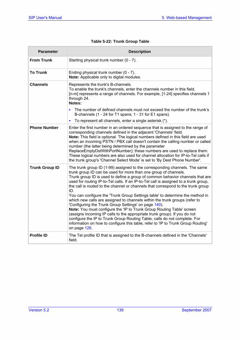
Version 5.2 139 September 2007
SIP User's Manual 5. Web-based Management
Table 5-22: Trunk Group Table
Parameter Description
From Trunk Starting physical trunk number (0 - 7).
To Trunk Ending physical trunk number (0 - 7). Note: Applicable only to digital modules.
Channels Represents the trunk's B-channels. To enable the trunk's channels, enter the channels number in this field. [n-m] represents a range of channels. For example, [1-24] specifies channels 1 through 24. Notes: The number of defined channels must not exceed the number of the trunk’s
B-channels (1 - 24 for T1 spans; 1 - 31 for E1 spans). To represent all channels, enter a single asterisk (*).
Phone Number Enter the first number in an ordered sequence that is assigned to the range of corresponding channels defined in the adjacent 'Channels' field. Note: This field is optional. The logical numbers defined in this field are used when an incoming PSTN / PBX call doesn't contain the calling number or called number (the latter being determined by the parameter ReplaceEmptyDstWithPortNumber); these numbers are used to replace them.These logical numbers are also used for channel allocation for IP-to-Tel calls if the trunk group's 'Channel Select Mode' is set to 'By Dest Phone Number'.
Trunk Group ID The trunk group ID (1-99) assigned to the corresponding channels. The same trunk group ID can be used for more than one group of channels. Trunk group ID is used to define a group of common behavior channels that are used for routing IP-to-Tel calls. If an IP-to-Tel call is assigned to a trunk group, the call is routed to the channel or channels that correspond to the trunk group ID. You can configure the 'Trunk Group Settings table' to determine the method in which new calls are assigned to channels within the trunk groups (refer to 'Configuring the Trunk Group Settings' on page 140). Note: You must configure the 'IP to Trunk Group Routing Table' screen (assigns incoming IP calls to the appropriate trunk group). If you do not configure the IP to Trunk Group Routing Table, calls do not complete. For information on how to configure this table, refer to 'IP to Trunk Group Routing' on page 126.
Profile ID The Tel profile ID that is assigned to the B-channels defined in the 'Channels' field.

SIP User's Manual 140 Document #: LTRT-68806
Mediant 2000 & TP-1610 & TP-260/UNI
5.5.7 Configuring the Trunk Group Settings The Trunk Group Settings option is used to determine the method in which new calls are assigned to channels within each trunk group. If such a rule doesn't exist (for a specific Trunk group), the global rule, defined by the 'Channel Select Mode' parameter (Protocol Definition > General Parameters), applies.
You can also configure the Trunk Group Settings table using the ini file parameter TrunkGroupSettings (refer to 'Number Manipulation and Routing Parameters' on page 318).
To configure the Trunk Group Settings table, take these 5 steps:
1. Open the 'Trunk Group Settings' screen (Protocol Management menu > Trunk Group Settings).
Figure 5-25: Trunk Group Settings Screen
2. From the 'Routing Index' drop-down list, select the range of entries that you want to edit (up to 24 entries can be configured).
3. Configure the Trunk Group Settings table according to the table below.
4. Click the Submit button to save your changes.
5. To save the changes to flash memory, refer to 'Saving Configuration' on page 256.

Version 5.2 141 September 2007
SIP User's Manual 5. Web-based Management
Table 5-23: Hunt Group Settings Parameters
Mode Description
Trunk Group ID Trunk Group ID to which you want to determine the method in which new calls are assigned to channels within the trunk group.
Channel Select Mode
Method in which new calls are assigned to channels within the Trunk Group entered in the 'Trunk Group ID' field: By Dest Phone Number = Selects the gateway port according to the called
number (refer to the note below). Cyclic Ascending = Selects the next available channel in an ascending cycle
order. Always select the next higher channel number in the Trunk Group. When the gateway reaches the highest channel number in the Trunk Group, it selects the lowest channel number in the Trunk Group and then starts ascending again (default).
Ascending = Selects the lowest available channel. It always starts at the lowest channel number in the Trunk Group and if that channel is not available, it selects the next higher channel.
Cyclic Descending = Selects the next available channel in descending cycle order. It always selects the next lower channel number in the Trunk Group. When the gateway reaches the lowest channel number in the Trunk Group, it selects the highest channel number in the Trunk Group and then start descending again.
Descending = Selects the highest available channel. It always starts at the highest channel number in the Trunk Group and if that channel is not available, selects the next lower channel.
Dest Number + Cyclic Ascending = It first selects the gateway port according to the called number (refer to the note below). If the called number isn't found, then it selects the next available channel in ascending cyclic order. Note that if the called number is found, but the port associated with this number is busy, the call is released.
By Source Phone Number = Selects the gateway port according to the calling number.
Trunk Cyclic Ascending = Selects the gateway port from the first channel of the next trunk (next to the trunk from which the previous channel was allocated).
Registration Mode Registration mode for the Trunk Group: Per Endpoint = separate registration for each channel in the Trunk Group. Per Gateway = single registration for the whole Trunk Group (default). Don't Register
Note: The internal numbers of the gateway's channels are defined in the 'Trunk Group Table' under the 'Phone Number' column. For detailed information on the 'Trunk Group Table', refer to 'Configuring the Trunk Group Table' on page 138).

SIP User's Manual 142 Document #: LTRT-68806
Mediant 2000 & TP-1610 & TP-260/UNI
5.5.8 Configuring the Digital Gateway Parameters The 'Digital Gateway' screen is used to configure miscellaneous digital parameters.
To configure the digital gateway parameters, take these 4 steps:
1. Open the 'Digital gateway Parameters' screen (Protocol Management menu > Digital Gateway Parameters).
Figure 5-26: Digital Gateway Parameters Screen
2. Configure the Digital Gateway parameters according to the table below.
3. Click the Submit button to save your changes.
4. To save the changes to flash memory, refer to 'Saving Configuration' on page 256.

Version 5.2 143 September 2007
SIP User's Manual 5. Web-based Management
Table 5-24: Digital Gateway Parameters
Parameter Description
B-channel Negotiation [BchannelNegotiation]
Determines the ISDN B-Channel negotiation mode. [0] Preferred = Preferred [1] Exclusive = Exclusive (default) [2] Any = Any
Notes: • Applicable to ISDN protocols. • The option Any is only applicable if TerminationSide = 0 (i.e.,
User side). Swap Redirect and Called Numbers [SwapRedirectNumber]
[0] No = Don't change numbers (default) [1] Yes = Incoming ISDN call that includes redirect number
(sometimes referred as 'original called number') uses this number instead of the called number.
MFC R2 Category [R2Category]
MFC R2 Calling Party Category (CPC). The parameter provides information on calling party such as National or International call, Operator or Subscriber and Subscriber priority. The parameter range is 1 to 15, defining one of the MFC R2 tones.
Disconnect Call on Detection of Busy Tone [DisconnectOnBusyTone]
[0] No = Do not disconnect call on detection of busy tone. [1] Yes = Disconnect call on detection of busy tone (default).
Note: This parameter is applicable to CAS and ISDN protocols.
Enable TDM Tunneling [EnableTDMoverIP]
[0] Disable = Disabled (default). [1] Enable = TDM Tunneling is enabled.
When TDM Tunneling is enabled, the originating gateway automatically initiates SIP calls from all enabled B-channels belonging to the E1/T1/J1 spans that are configured with the 'Transparent' protocol. The called number of each call is the internal phone number of the B-channel that the call originates from. The IP to Trunk Group routing table is used to define the destination IP address of the terminating gateway. The terminating gateway automatically answers these calls if its E1/T1 protocol is set to 'Transparent' (ProtocolType = 5).
Send Screening Indicator to IP [ScreeningInd2IP]
The parameter can overwrite the calling number screening indication for ISDN Tel-to-IP calls. [-1] Not Configured = not configured (interworking from ISDN to
IP) or set to 0 for CAS. [0] User Provided = user provided, not screened. [1] User Passed = user provided, verified and passed. [2] User Failed = user provided, verified and failed. [3] Network Provided = network provided.
Note: Applicable only if Remote Party ID (RPID) header is enabled.

SIP User's Manual 144 Document #: LTRT-68806
Mediant 2000 & TP-1610 & TP-260/UNI
Table 5-24: Digital Gateway Parameters
Parameter Description
Send Screening Indicator to ISDN [ScreeningInd2ISDN]
Overwrites the screening indicator of the calling number for IP Tel (ISDN) calls. [-1] Not Configured = Not configured (interworking from IP to
ISDN) (default). [0] User Provided = user provided, not screened. [1] User Passed = user provided, verified and passed. [2] User Failed = user provided, verified and failed. [3] Network Provided = network provided.
Add IE in SETUP [AddIEinSetup]
This parameter enables to add an optional Information Element data (in hex format) to ISDN SETUP message. For example: to add the following IE: '0x20,0x02,0x00,0xe1', define: 'AddIEinSetup = 200200e1'. Note: This IE is sent from the Trunk Group IDs defined by the parameter 'SendIEonTG'.
Trunk Groups to Send IE [SendIEonTG]
A list of Trunk Group IDs (up to 50 characters) from where the optional ISDN IE, defined by the parameter AddIEinSetup is sent.For example: 'SendIEonTG = 1,2,4,10,12,6'.
Enable User-to-User IE for Tel to IP [EnableUUITel2IP]
[0] Disable = Disabled (default). [1] Enable = Enable transfer of User-to-User Information
Element (UUIE) from PRI to SIP. The gateway supports the following interworking: SETUP to INVITE, CONNECT to 200 OK, and USER INFORMATION to INFO. Note: The interworking of User-to-User IE to SIP INFO is supported only on 4ESS PRI variant.
Enable User-to-User IE for IP to Tel [EnableUUIIP2Tel]
[0] Disable = Disabled (default). [1] Enable = Enable transfer of (UUIE) from SIP INVITE
message to PRI Setup message. The gateway supports the following interworking: INVITE to SETUP, 200 OK to CONNECT, and INFO to USER INFORMATION. Note: The interworking of User-to-User IE to SIP INFO is supported only on 4ESS PRI variant.

Version 5.2 145 September 2007
SIP User's Manual 5. Web-based Management
Table 5-24: Digital Gateway Parameters
Parameter Description
Enable ISDN Tunneling Tel to IP [EnableISDNTunnelingTel2IP]
Valid options include: [0] Disable = Disable (default). [1] Using Header = Enable ISDN Tunneling from ISDN PRI to
SIP using a proprietary SIP header. [2] Using Body = Enable ISDN Tunneling from ISDN PRI to SIP
using a dedicated message body. When ISDN Tunneling is enabled, the gateway sends all ISDN PRI messages using the correlated SIP messages. Setup is tunneled using INVITE, all mid-call messages are tunneled using INFO, and Disconnect/Release is tunneled using BYE. The raw data from the ISDN is inserted into a proprietary SIP header (X-ISDNTunnelingInfo) or a dedicated message body (application/isdn) in the SIP messages.
Note: It is necessary to set the parameter ISDNDuplicateQ931BuffMode to 128 (duplicate all messages) for this mechanism to function.
Enable QSIG Tunneling [EnableQSIGTunneling]
Enables QSIG tunneling over SIP according to <draft-elwell-sipping-qsig-tunnel-03>. [0] Disable = Disable (default). [1] Enable = Enable QSIG tunneling from QSIG to SIP and vice
versa. When QSIG tunneling is enabled, all QSIG messages are sent as raw data in corresponding SIP messages using a dedicated message body. Note that QSIG tunneling must be enabled on both the originating and terminating gateways. Note: It is necessary to set the parameter ISDNDuplicateQ931BuffMode to 128 (duplicate all messages) so that this mechanism can function.
Enable ISDN Tunneling IP to Tel [EnableISDNTunnelingIP2Tel]
Valid options include: [0] Disable = Disable (default). [1] Using Header = Enable ISDN Tunneling from SIP to ISDN
PRI using a proprietary SIP header. [2] Using Body = Enable ISDN Tunneling from SIP to ISDN PRI
using a dedicated message body. When ISDN Tunneling is enabled, the gateway extracts raw data received in a proprietary SIP header (X-ISDNTunnelingInfo) or a dedicated message body (application/isdn) in the SIP messages and sends the data as ISDN messages to the PSTN side.

SIP User's Manual 146 Document #: LTRT-68806
Mediant 2000 & TP-1610 & TP-260/UNI
Table 5-24: Digital Gateway Parameters
Parameter Description
ISDN Transfer On Connect [SendISDNTransferOnConnect]
[0] Alert = Enable ISDN Transfer if outgoing call is in Alert state (default).
[1] Connect = Enable ISDN Transfer only if outgoing call is in Connect state.
This parameter is used for the ECT/TBCT/RLT ISDN Transfer methods. Usually, the gateway requests the PBX to connect an incoming and an outgoing call. This parameter determines if the outgoing call (from the gateway to the PBX) must be connected before the transfer is initiated.
Remove CLI when Restricted [RemoveCLIWhenRestricted]
Determines (for IP to Tel calls) whether the Calling Number IE and Calling Name IE are removed from the outgoing ISDN Setup message if the presentation is set to Restricted. [0] No = IE aren't removed (default). [1] Yes = IE are removed.
Default Cause Mapping From ISDN to SIP [DefaultCauseMapISDN2IP]
Defines a single default ISDN Release Cause that is used (in ISDN to IP calls) instead of all received release causes except when the following Q.931 cause values are received: Normal Call Clearing (16), User Busy (17), No User Responding (18) or No Answer from User (19). The range is valid Q.931 release causes (0 to 127). The default value is 0 (indicates that the parameter is not configured - static mapping is used).
Add Prefix to Redirect Number [Prefix2RedirectNumber]
Defines a string Prefix that is added to the Redirect number received from the Tel side. This Prefix is added to the Redirect Number in the Diversion header. The valid range is an 8 character string. The default is an empty string.
Enable Calling Party Category [EnableCallingPartyCategory]
Determines whether Calling Party Category is relayed between SIP and PRI. [0] Disable = Don't relay the Calling Party Category between
SIP and PRI (default). [1] Enable = Calling Party Category is relayed between SIP
and PRI. If enabled, the Calling Party Category received in the OLI IE of an incoming SETUP is relayed to the From/P-Asserted-Id headers of the outgoing INVITE message and vice versa. For example: From:<sip:2000;[email protected]>;tag=1c1806157451Note: This feature is supported only when using NI-2 PRI variant.
MLPP (Multi-level Precedence & Preemption)
Call Priority Mode [CallPriorityMode]
Enables Priority Calls handling. Valid options include: [0] Disable = Disable (default). [1] MLPP = Priority Calls handling is enabled.

Version 5.2 147 September 2007
SIP User's Manual 5. Web-based Management
Table 5-24: Digital Gateway Parameters
Parameter Description
MLPP Default Namespace [MLPPDefaultNamespace]
Determines the Namespace used for MLPP calls received from theISDN side and destined for the Application Server. The Namespace value is not present in the Precedence IE of the PRI SETUP message. Therefore, the value is used in the Resource-Priority header of the outgoing SIP INVITE request. Valid options include: [1] DSN = DSN (default) [2] DOD = DOD [3] DRSN = DRSN
Default Call Priority [SIPDefaultCallPriority]
Defines the default call priority for MLPP calls. Valid options include: [0] 0 = ROUTINE (default) [2] 2 = PRIORITY [6] 6 = IMMEDIATE [8] 8 = FLASH-OVERRIDE [9] 9 = FLASH-OVERRIDE-OVERRIDE
If the incoming SIP INVITE request doesn't contain a valid priority value in the Resource-Priority header, the default value is used in the Precedence IE (after translation to the relevant ISDN Precedence value) of the outgoing PRI SETUP message. If the incoming PRI SETUP message doesn't contain a valid Precedence Level value, the default value is used in the Resource-Priority header of the outgoing SIP INVITE request. In this scenario, the character string is sent without translation to a numerical value.
MLPP DiffServ [MLPPDiffserv]
Defines the DiffServ value (DSCP) used in IP packets containing SIP messages that are related to MLPP calls. The valid range is 0 to 63. The default value is 50.
5.5.9 Configuring the Advanced Applications The Advanced Applications submenu enables you to configure advanced applications such as RADIUS.
5.5.9.1 Configuring RADIUS Accounting Parameters
The 'RADIUS Parameters' screen is used for configuring the Remote Authentication Dial In User Service (RADIUS) accounting parameters.

SIP User's Manual 148 Document #: LTRT-68806
Mediant 2000 & TP-1610 & TP-260/UNI
To configure the RADIUS parameters, take these 4 steps:
1. Open the ‘RADIUS Parameters' screen (Protocol Management menu > Advanced Applications submenu > RADIUS Parameters).
Figure 5-27: RADIUS Parameters Screen
2. Configure the RADIUS accounting parameters according to the table below.
3. Click the Submit button to save your changes.
4. To save the changes to flash memory, refer to 'Saving Configuration' on page 256.
Table 5-25: RADIUS Parameters
Parameter Description
Enable RADIUS EnableRADIUS
Enables or disables the RADIUS application. Valid options include: [0] Disables = disables RADIUS application (default) [1] Enable = enables RADIUS application
RADIUS Accounting Server IP Address [RADIUSAccServerIP]
IP address of the RADIUS accounting server.
RADIUS Accounting Port [RADIUSAccPort]
Port of the RADIUS accounting server. The default value is 1646.
RADIUS Accounting Type [RADIUSAccountingType]
Determines when the RADIUS accounting messages are sent to the RADIUS accounting server. Valid options include: [0] At Call Release = Sent at the release of the call only (default). [1] At Connect and Release = Sent at the connect and release of the
call. [2] At Setup and Release = Sent at the setup and release of the call.
AAA Indications [AAAIndications]
Determines which Authentication, Authorization and Accounting (AAA) indications to use. Valid options include: [0] None = No indications (default). [3] Accounting Only = Only accounting indications are used.

Version 5.2 149 September 2007
SIP User's Manual 5. Web-based Management
5.5.9.2 Configuring the Voice Mail (VM) Parameters
The 'Voice Mail' screen is used to configure the Voice Mail (VM) parameters. The VM application applies only to FXO/CAS gateways. For detailed information on VM, refer to the CPE Configuration Guide for Voice Mail User's Manual.
To configure the VM parameters, take these 4 steps:
1. Open the 'Voice Mail' screen (Protocol Management menu > Advanced Applications submenu > Voice Mail option).
2. Configure the Voice Mail parameters according to the table below.
3. Click the Submit button to save your changes.
4. To save the changes to flash memory, refer to 'Saving Configuration' on page 256.

SIP User's Manual 150 Document #: LTRT-68806
Mediant 2000 & TP-1610 & TP-260/UNI
Table 5-26: Voice Mail Parameters
Parameter Description
General
Voice Mail Interface [VoiceMailInterface]
Enables the VM application on the gateway and determines the communication method used between the PBX and the gateway. [0] None (default) [1] DTMF [2] SMDI [3] QSIG [4] SETUP Only (ISDN)
Line Transfer Mode [LineTransferMode]
Determines the transfer method used by the gateway. [0] None = IP (default). [1] Blind = PBX blind transfer. After receiving a REFER message from
the IP side, the FXO sends a hook-flash to the PBX, dials the digits (that are received in the Refer-To header), and then immediately drops the line (on-hook). The PBX performs the transfer internally.
[2] Semi Supervised = PBX Semi-Supervised transfer. After receiving a REFER message from the IP side, the FXO sends a hook-flash to the PBX, and then dials the digits (that are received in the Refer-To header). If no Busy or Reorder tones are detected (within approximately 2 seconds), the gateway completes the call transfer by releasing the line; otherwise, the transfer is cancelled, the gateway sends a SIP NOTIFY message with a failure reason in the NOTIFY body (such as 486 if busy tone detected), and generates an additional hook-flash towards the FXO line to restore connection to the original call.
[3] Supervised = PBX Supervised transfer. After receiving a REFER message from the IP side, the FXO sends a hook-flash to the PBX, and then dials the digits (that are received in the Refer-To header). The FXO waits for connection of the transfer call and if speech is detected (e.g., "hello") within approximately 2 seconds, the gateway completes the call transfer by releasing the line; otherwise, the transfer is cancelled, the gateway sends a SIP NOTIFY message with a failure reason in the NOTIFY body (such as 486 if busy tone detected), and generates an additional hook-flash towards the FXO line to restore connection to the original call.
For additional information, refer to the CPE SIP Configuration Guide for IP Voice Mail. Note: Applicable only for CAS protocols.
Digit Patterns The following digit pattern parameters apply only to VM applications that use the DTMF communication method. For the available patterns' syntaxes, refer to the CPE Configuration Guide for Voice Mail.
Forward on Busy Digit Pattern (Internal) [DigitPatternForwardOnBusy]
Determines the digit pattern used by the PBX to indicate 'call forward on busy' when the original call is received from an internal extension. The valid range is a 120-character string.

Version 5.2 151 September 2007
SIP User's Manual 5. Web-based Management
Table 5-26: Voice Mail Parameters
Parameter Description
Forward on No Answer Digit Pattern (Internal) [DigitPatternForwardOnNoAnswer]
Determines the digit pattern used by the PBX to indicate 'call forward on no answer' when the original call is received from an internal extension.The valid range is a 120-character string.
Forward on Do Not Disturb Digit Pattern (Internal) [DigitPatternForwardOnDND]
Determines the digit pattern used by the PBX to indicate 'call forward on do not disturb' when the original call is received from an internal extension. The valid range is a 120-character string.
Forward on No Reason Digit Pattern (Internal) [DigitPatternForwardNoReason]
Determines the digit pattern used by the PBX to indicate 'call forward with no reason' when the original call is received from an internal extension. The valid range is a 120-character string.
Forward on Busy Digit Pattern (External) [DigitPatternForwardOnBusyExt]
Determines the digit pattern used by the PBX to indicate 'call forward on busy' when the original call is received from an external line and not an internal extension. The valid range is a 120-character string.
Forward on No Answer Digit Pattern (External) [DigitPatternForwardOnNoAnswerExt]
Determines the digit pattern used by the PBX to indicate 'call forward on no answer' when the original call is received from an external line and not an internal extension. The valid range is a 120-character string.
Forward on Do Not Disturb Digit Pattern (External) [DigitPatternForwardOnDNDExt]
Determines the digit pattern used by the PBX to indicate 'call forward on do not disturb' when the original call is received from an external line and not an internal extension. The valid range is a 120-character string.
Forward on No Reason Digit Pattern (External) [DigitPatternForwardNoReasonExt]
Determines the digit pattern used by the PBX to indicate 'call forward with no reason' when the original call is received from an external line and not an internal extension. The valid range is a 120-character string.
Internal Call Digit Pattern [DigitPatternInternalCall]
Determines the digit pattern used by the PBX to indicate an internal call.The valid range is a 120-character string.
External Call Digit Pattern [DigitPatternExternalCall]
Determines the digit pattern used by the PBX to indicate an external call.The valid range is a 120-character string.
Disconnect Call Digit Pattern [TelDisconnectCode]
Determines a digit pattern that, when received from the Tel side, indicates the gateway to disconnect the call. The valid range is a 25-character string.
MWI
MWI Off Digit Pattern [MWIOffCode]
Determines a digit code used by the gateway to notify the PBX that there aren't any messages waiting for a specific extension. This code is added as prefix to the dialed number. The valid range is a 25-character string.
MWI On Digit Pattern [MWIOnCode]
Determines a digit code used by the gateway to notify the PBX of messages waiting for a specific extension. This code is added as prefix to the dialed number. The valid range is a 25-character string.

SIP User's Manual 152 Document #: LTRT-68806
Mediant 2000 & TP-1610 & TP-260/UNI
Table 5-26: Voice Mail Parameters
Parameter Description
MWI Suffix Pattern [MWISuffixCode]
Determines a digit code used by the gateway as a suffix for MWIOnCode and MWIOffCode. This suffix is added to the generated DTMF string after the extension number. The valid range is a 25-character string.
SMDI
Enable SMDI [SMDI]
Enables Simplified Message Desk Interface (SMDI) interface on the gateway. [0] Disable = Normal serial (default). [1] Bellcore [2] Ericsson MD-110 [3] NEC (ICS)
Note: When the RS-232 connection is used for SMDI messages (Serial SMDI), it cannot be used for other applications, for example, to access the Command Line Interface.
SMDI Timeout [SMDITimeOut]
Determines the time (in msec) that the gateway waits for an SMDI Call Status message before or after a Setup message is received. This parameter is used to synchronize the SMDI and analogCAS interfaces. If the timeout expires and only an SMDI message was received, the SMDI message is dropped. If the timeout expires and only a Setup message was received, the call is established. The valid range is 0 to 10000 (10 seconds). The default value is 2000.
5.6 Network Settings The Network Settings menu allows you to configure the following:
IP Settings (refer to 'Configuring the IP Settings' on page 153)
Application Settings (refer to 'Configuring the Application Settings' on page 157)
NFS Settings (refer to 'Configuring the NFS Settings' on page 159)
IP Routing Table (refer to 'Configuring the IP Routing Table' on page 162)
VLAN Settings (refer to 'Configuring the VLAN Settings' on page 164)

Version 5.2 153 September 2007
SIP User's Manual 5. Web-based Management
5.6.1 Configuring the IP Settings The 'IP Settings' screen is used for configuring various IP networking parameters.
To configure the IP Settings parameters, take these 4 steps:
1. Open the 'IP Settings' screen (Advanced Configuration menu > Network Settings > IP Settings option).
Figure 5-28: IP Settings Screen
2. Configure the IP Settings according to the table below.
3. Click the Submit button to save your changes.
4. To save the changes to flash memory, refer to 'Saving Configuration' on page 256.

SIP User's Manual 154 Document #: LTRT-68806
Mediant 2000 & TP-1610 & TP-260/UNI
Table 5-27: Network Settings -- IP Settings Parameters
Parameter Description
IP Networking Mode [EnableMultipleIPs]
Enables / disables the Multiple IPs mechanism. [0] Single IP Network = Single IP network (default). [1] Multiple IP Network = Multiple IP networks. [1] Dual IP (Media & Control) = Multiple IP networks. [1] Dual IP (OAM & Control) = Multiple IP networks. [1] Dual IP (OAM & Medial) = Multiple IP networks.
For detailed information on Multiple IPs, refer to 'Multiple IPs' on page 373.
IP Address IP address of the gateway. Enter the IP address in dotted format notation, for example 10.8.201.1.Notes: A warning message is displayed (after clicking the button Submit) if
the entered value is incorrect. After changing the IP address you must reset the gateway.
Subnet Mask Subnet mask of the gateway. Enter the subnet mask in dotted format notation, for example 255.255.0.0 Notes: A warning message is displayed (after clicking the button Submit) if
the entered value is incorrect. After changing the subnet mask, the gateway must be reset.
Default Gateway Address IP address of the default gateway used by the gateway. Enter the IP address in dotted format notation, for example 10.8.0.1. Notes: A warning message is displayed (after clicking the button Submit) if
the entered value is incorrect. After changing the default gateway IP address, the gateway must be
reset. For detailed information on multiple routers support, refer to 'Multiple Routers Support' on page 371.
OAM Network Settings (available only in Multiple IPs and Dual IP modes)
IP Address [LocalOAMIPAddress]
The gateway's source IP address in the OAM network. The default value is 0.0.0.0.
Subnet Mask [LocalOAMSubnetMask]
The gateway's subnet mask in the OAM network. The default subnet mask is 0.0.0.0.
Default Gateway Address [LocalOAMDefaultGW]
N/A. Use the IP Routing table instead (refer to 'Configuring the IP Routing Table' on page 162).
Control Network Settings (available only in Multiple IPs and Dual IP modes)
IP Address [LocalControlIPAddress]
The gateway's source IP address in the Control network. The default value is 0.0.0.0.
Subnet Mask [LocalControlSubnetMask]
The gateway's subnet mask in the Control network. The default subnet mask is 0.0.0.0.

Version 5.2 155 September 2007
SIP User's Manual 5. Web-based Management
Table 5-27: Network Settings -- IP Settings Parameters
Parameter Description
Default Gateway Address [LocalControlDefaultGW]
N/A. Use the IP Routing table instead (refer to 'Configuring the IP Routing Table' on page 162).
Media Network Settings (available only in Multiple IPs and Dual IP modes)
IP Address [LocalMediaIPAddress]
The gateway's source IP address in the Media network. The default value is 0.0.0.0.
Subnet Mask [LocalMediaSubnetMask]
The gateway's subnet mask in the Media network. The default subnet mask is 0.0.0.0.
Default Gateway Address [LocalMediaDefaultGW]
The gateway's default gateway IP address in the Media network. The default value is 0.0.0.0.
DNS Settings
DNS Primary Server IP [DNSPriServerIP]
IP address of the primary DNS server. Enter the IP address in dotted format notation, for example 10.8.2.255.Note: To use Fully Qualified Domain Names (FQDN) in the Tel to IP Routing table, you must define this parameter.
DNS Secondary Server IP [DNSSecServerIP]
IP address of the second DNS server. Enter the IP address in dotted format notation, for example 10.8.2.255.
DHCP Settings
Enable DHCP [DHCPEnable]
[0] Disable = Disable DHCP support on the gateway (default). [1] Enable = Enable DHCP support on the gateway.
After the gateway is powered up, it attempts to communicate with a BootP server. If a BootP server is not responding and if DHCP is enabled, then the gateway attempts to get its IP address and other network parameters from the DHCP server. Notes: After you enable the DHCP Server (using the Embedded Web
Server) follow this procedure: 1. Click the Submit button. 2. Save the configuration (refer to 'Saving Configuration' on page 256). 3. Reset the gateway directly (reset via Embedded Web Server doesn't trigger the BootP/DHCP procedure and the parameter DHCPEnable reverts to 0).
Throughout the DHCP procedure the BootP/TFTP application must be deactivated. Otherwise, the gateway receives a response from the BootP server instead of the DHCP server.
For additional information on DHCP, refer to the SIP Series Reference Manual).
The DHCPEnable is a special 'Hidden' parameter. Once defined and saved in flash memory, its assigned value doesn't revert to its default even if the parameter doesn't appear in the ini file.
NAT Settings
NAT IP Address [StaticNatIP]
Global gateway IP address. Define if static Network Address Translation (NAT) device is used between the gateway and the Internet.

SIP User's Manual 156 Document #: LTRT-68806
Mediant 2000 & TP-1610 & TP-260/UNI
Table 5-27: Network Settings -- IP Settings Parameters
Parameter Description
Differential Services. For detailed information on IP QoS via Differentiated Services, refer to 'IP QoS via Differentiated Services (DiffServ)' on page 372.
Network QoS [NetworkServiceClassDiffServ]
Sets the DiffServ value for Network service class content. The valid range is 0 to 63. The default value is 48.
Media Premium QoS [PremiumServiceClassMediaDiffServ]
Sets the DiffServ value for Premium Media service class content (only if IPDiffServ is not set in the selected IP Profile). The valid range is 0 to 63. The default value is 46. Note: The value for the Premium Control DiffServ is determined by (according to priority): (1) IPDiffServ value in the selected IP Profile. (2) PremiumServiceClassMediaDiffServ.
Control Premium QoS [PremiumServiceClassControlDiffServ]
Sets the DiffServ value for Premium Control service class content (only if ControlIPDiffserv is not set in the selected IP Profile). The valid range is 0 to 63. The default value is 40. Note: The value for the Premium Control DiffServ is determined by (according to priority): (1) ControlPDiffserv value in the selected IP Profile. (2) PremiumServiceClassControlDiffServ.
Gold QoS [GoldServiceClassDiffServ]
Sets the DiffServ value for the Gold service class content. The valid range is 0 to 63. The default value is 26.
Bronze QoS [BronzeServiceClassDiffServ]
Sets the DiffServ value for the Bronze service class content. The valid range is 0 to 63. The default value is 10.

Version 5.2 157 September 2007
SIP User's Manual 5. Web-based Management
5.6.2 Configuring the Application Settings The 'Application Settings' screen is used for configuring various application parameters (e.g., for Telnet).
To configure the Application Settings parameters, take these 4 steps:
1. Open the 'Application Settings' screen (Advanced Configuration menu > Network Settings > Application Settings option).
Figure 5-29: Application Settings Screen
2. Configure the Application Settings according to the table below.
3. Click the Submit button to save your changes.
4. To save the changes to flash memory, refer to 'Saving Configuration' on page 256.

SIP User's Manual 158 Document #: LTRT-68806
Mediant 2000 & TP-1610 & TP-260/UNI
Table 5-28: Network Settings, Application Settings Parameters
Parameter Description
NTP Settings
For detailed information on Network Time Protocol (NTP), refer to 'Simple Network Time Protocol Support' on page 372.
NTP Server IP Address [NTPServerIP]
IP address (in dotted format notation) of the NTP server. The default IP address is 0.0.0.0 (the internal NTP client is disabled).
NTP UTC Offset [NTPServerUTCOffset]
Defines the UTC (Universal Time Coordinate) offset (in seconds) from the NTP server. The default offset is 0. The offset range is -43200 to 43200 seconds.
NTP Update Interval [NTPUpdateInterval]
Defines the time interval (in seconds) the NTP client requests for a time update. The default interval is 86400 seconds (24 hours). The range is 0 to 214783647 seconds. Note: It isn't recommended to be set beyond one month (2592000 seconds).
Telnet Settings
Embedded Telnet Server [TelnetServerEnable]
Enables or disables the embedded Telnet server. Telnet is disabled by default for security reasons. [0] Disable (default). [1] Enable (Unsecured). [2] Enable Secured (SSL).
Telnet Server TCP Port [TelnetServerPort]
Defines the port number for the embedded Telnet server. The valid range is all valid port numbers. The default port is 23.
Telnet Server Idle Timeout [TelnetServerIdleDisconnect]
Sets the timeout for disconnection of an idle Telnet session (in minutes). When set to zero, idle sessions are not disconnected. The valid range is any value. The default value is 0.
SSH Server Enable [SSHServerEnable]
Enables or disables the embedded Secure SHell (SSH) server. [0] Disable = Disable SSH server (default) [1] Enable = Enable
SSH Server Port [SSHServerPort]
Defines the port number for the embedded SSH server. Range is any valid port number. Default is port 23.

Version 5.2 159 September 2007
SIP User's Manual 5. Web-based Management
Table 5-28: Network Settings, Application Settings Parameters
Parameter Description
STUN Settings
Enable STUN [EnableSTUN]
[0] Disable = STUN protocol is disabled (default). [1] Enable = STUN protocol is enabled.
When enabled, the gateway functions as a STUN client and communicates with a STUN server located in the public Internet. STUN is used to discover whether the gateway is located behind a NAT and the type of that NAT. In addition, it is used to determine the IP addresses and port numbers that the NAT assigns to outgoing signaling messages (using SIP) and media streams (using RTP, RTCP and T.38). STUN works with many existing NAT types, and does not require any special behavior from them. This parameter cannot be changed on-the-fly and requires a gateway reset. For detailed information on STUN, refer to 'STUN' on page 367. Note: For defining the STUN server domain name, use the ini file parameter STUNServerDomainName (refer to 'Networking Parameters' on page 273).
STUN Server Primary IP [STUNServerPrimaryIP]
Defines the IP address of the primary STUN server. The valid range is the legal IP addresses. The default value is 0.0.0.0.
STUN Server Secondary IP [STUNServerSecondaryIP]
Defines the IP address of the secondary STUN server. The valid range is the legal IP addresses. The default value is 0.0.0.0.
NFS Settings
NFS Table For detailed information on configuring the NFS table, refer to 'Configuring the NFS Settings' on page 159.
5.6.3 Configuring the NFS Settings Network File System (NFS) enables the gateway to access a remote server's shared files and directories and to handle them as if they're located locally. A file system, the NFS is independent of machine types, OSs, and network architectures. Up to five different NFS file systems can be configured.
NFS is utilized by the gateway to load the cmp, ini and configuration files via the Automatic Update mechanism (refer to 'Automatic Update Mechanism' on page 245).
Note that an NFS file server can share multiple file systems. There must be a separate row for each remote file system shared by the NFS file server that needs to be accessed by the gateway.

SIP User's Manual 160 Document #: LTRT-68806
Mediant 2000 & TP-1610 & TP-260/UNI
To configure the NFS Settings parameters, take these 7 steps:
1. Open the 'Application Settings' screen (Advanced Configuration menu > Network Settings > Application Settings option); the 'Application Settings' screen is displayed (refer to 'Configuring the Application Settings' on page 157).
2. Open the 'NFS Settings' screen by clicking the NFS Table arrow sign (-->).
Figure 5-30: NFS Settings Screen
3. To add a remote NFS file system, select an available line number from the 'Line Number' drop-down list.
4. Click the Add an Empty Line button; an empty line appears.
5. Configure the NFS Settings according to the table below.
6. Click the Apply New Settings button; the remote NFS file system is mounted immediately. Check the Syslog server for the 'NFS mount was successful' message.
7. To save the changes to flash memory, refer to 'Saving Configuration' on page 256.
Note: To avoid terminating calls in progress, a row must not be deleted or modified while the blade is currently accessing files on that remote NFS file system.
To delete a remote NFS file system, take these 3 steps:
1. Select the Edit radio button for the row to be deleted.
2. Click the Delete Line button; the row is deleted.
3. To save the changes to flash memory, refer to 'Saving Configuration' on page 256.

Version 5.2 161 September 2007
SIP User's Manual 5. Web-based Management
To modify an existing remote NFS file system, take these 4 steps:
1. Select the Edit radio button for the row to be modified.
2. Change the values on the selected row according to your requirements.
3. Click the Apply New Settings button; the remote NFS file system is mounted using the new settings. Check the Syslog server for the 'NFS mount was successful' message.
4. To save the changes to flash memory, refer to 'Saving Configuration' on page 256.
Table 5-29: Network Settings -- NFS Settings Parameters
Parameter Description
Line Number [NFSServers_Index]
The row index of the remote file system. The valid range is 0 to 4.
Host / IP [NFSServers_HostOrIP]
The domain name or IP address of the NFS server. If a domain name is provided, a DNS server must be configured.
Root Path [NFSServers_RootPath]
Path to the root of the remote file system in the format: '/' + [path]. For example, /audio.
The combination of Host / IP and Root Path must be unique for each row in the table. For example, there must be only one row in the table with a Host / IP of 192.168.1.1 and Root Path of /audio.
NFS Version [NFSServers_NfsVersion] NFS version to use with the remote file system, 2 or 3 (default).
Auth Type [NFSServers_AuthType]
Identifies the authentication method used with the remote file system. [0] Auth NULL. [1] Auth UNIX (default).
UID [NFSServers_UID]
User ID used in authentication if using Auth UNIX. The valid range is 0 to 65537. The default is 0.
GID [NFSServers_GID]
Group ID used in authentication if using Auth UNIX. The valid range is 0 to 65537. The default is 1
VLAN Type [NFSServers_VlanType]
The VLAN, OAM [0] or MEDIA [1], to use when accessing the remote file system. The default is to use the media VLAN. This parameter applies only if VLANs are enabled or if Multiple IPs is configured (refer to 'VLANS and Multiple IPs' on page 373).
Below shows an example of an NFS table definition via ini file using parameter tables (for information on ini file parameter tables, refer to 'Configuring Parameter Tables Using the ini File' on page 269).
[NFSServers] FORMAT NFSServers_Index = NFSServers_HostOrIP, NFSServers_RootPath, NFSServers_NfsVersion, NFSServers_AuthType, NFSServers_UID, NFSServers_GID, NFSServers_VlanType; NFSServers 1 = 101.1.13, /audio1, 3, 1, 0, 1, 1; [\NFSServers]

SIP User's Manual 162 Document #: LTRT-68806
Mediant 2000 & TP-1610 & TP-260/UNI
5.6.4 Configuring the IP Routing Table The 'IP Routing Table' screen is used by the gateway to determine IP routing rules. It can be used, for example, to define static routing rules for the OAM and Control networks since a default gateway isn't supported for these networks (refer to 'Multiple IPs' on page 373). Before sending an IP packet, the gateway searches this table for an entry that matches the requested destination host / network. If such an entry is found, the gateway sends the packet to the indicated router. If no explicit entry is found, the packet is sent to the default gateway (configured in the 'IP Settings' screen -- refer to 'Configuring the IP Settings' on page 153). Up to 50 routing entries are available.
To configure the IP Routing table, take these 3 steps:
1. Open the 'IP Routing Table' screen (Advanced Configuration menu > Network Settings > Routing Table option).
Figure 5-31: IP Routing Tablre Screen
2. Use the 'Add a new table entry' pane to add a new routing rule. Each field in the IP routing table is described in the table below.
3. Click the button Add New Entry; the new routing rule is added to the IP routing table.
Table 5-30: IP Routing Table Column Description
Column Name [ini File Parameter Name]
Description
Delete Row To delete IP routing rules from the IP Routing Table, check the Delete Row check box in the rows of the routing rules you want to delete and click the button Delete Selected Entries; the routing rules are removed from the table.
Destination IP Address [RoutingTableDestinationsColumn]
Specifies the IP address of the destination host / network.
Destination Mask [RoutingTableDestinationMasksColumn]
Specifies the subnet mask of the destination host / network.

Version 5.2 163 September 2007
SIP User's Manual 5. Web-based Management
Table 5-30: IP Routing Table Column Description
Column Name [ini File Parameter Name]
Description
The address of the host / network you want to reach is determined by an AND operation that is applied on the fields 'Destination IP Address' and 'Destination Mask'. For example: To reach the network 10.8.x.x, enter 10.8.0.0 in the field 'Destination IP Address' and 255.255.0.0 in the field 'Destination Mask'. As a result of the AND operation, the value of the last two octets in the field 'Destination IP Address' is ignored. To reach a specific host, enter its IP address in the field 'Destination IP Address' and 255.255.255.255 in the field 'Destination Mask'.
Gateway IP Address [RoutingTableGatewaysColumn]
Specifies the IP address of the router to which the packets are sent if their destination matches the rules in the adjacent columns.
TTL A read-only field that indicates the time period for which the specific routing rule is valid. The lifetime of a static route is infinite.
Hop Count [RoutingTableHopsCountColumn]
The maximum number of allowed routers between the gateway and destination.
Network Type [RoutingTableInterfacesColumn]
Specifies the network type the routing rule is applied to. [0] OAM (default). [1] Control. [2] Media.
For detailed information on the network types, refer to 'Multiple IPs' on page 373.
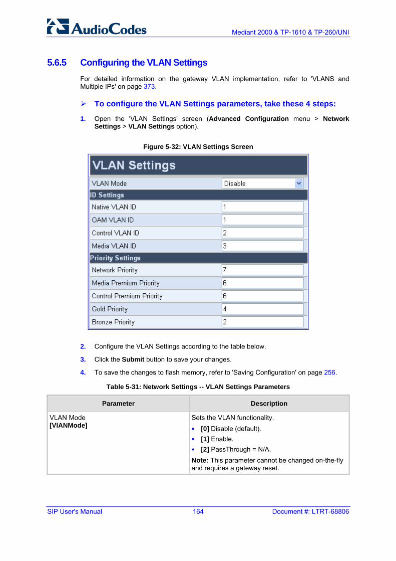
SIP User's Manual 164 Document #: LTRT-68806
Mediant 2000 & TP-1610 & TP-260/UNI
5.6.5 Configuring the VLAN Settings For detailed information on the gateway VLAN implementation, refer to 'VLANS and Multiple IPs' on page 373.
To configure the VLAN Settings parameters, take these 4 steps:
1. Open the 'VLAN Settings' screen (Advanced Configuration menu > Network Settings > VLAN Settings option).
Figure 5-32: VLAN Settings Screen
2. Configure the VLAN Settings according to the table below.
3. Click the Submit button to save your changes.
4. To save the changes to flash memory, refer to 'Saving Configuration' on page 256.
Table 5-31: Network Settings -- VLAN Settings Parameters
Parameter Description
VLAN Mode [VlANMode]
Sets the VLAN functionality. [0] Disable (default). [1] Enable. [2] PassThrough = N/A.
Note: This parameter cannot be changed on-the-fly and requires a gateway reset.

Version 5.2 165 September 2007
SIP User's Manual 5. Web-based Management
Table 5-31: Network Settings -- VLAN Settings Parameters
Parameter Description
IP Settings
Native VLAN ID [VLANNativeVlanID]
Sets the native VLAN identifier (PVID, Port VLAN ID). The valid range is 1 to 4094. The default value is 1.
OAM VLAN ID [VLANOamVlanID]
Sets the OAM (Operation, Administration and Management) VLAN identifier. The valid range is 1 to 4094. The default value is 1.
Control VLAN ID [VLANControlVlanID]
Sets the control VLAN identifier. The valid range is 1 to 4094. The default value is 2.
Media VLAN ID [VLANMediaVlanID]
Sets the media VLAN identifier. The valid range is 1 to 4094. The default value is 3.
Priority Settings
Network Priority [VLANNetworkServiceClassPriority]
Sets the priority for Network service class content. The valid range is 0 to 7. The default value is 7.
Media Premium Priority [VLANPremiumServiceClassMediaPriority]
Sets the priority for the Premium service class content and media traffic. The valid range is 0 to 7. The default value is 6.
Control Premium Priority [VLANPremiumServiceClassControlPriority]
Sets the priority for the Premium service class content and control traffic. The valid range is 0 to 7. The default value is 6.
Gold Priority [VLANGoldServiceClassPriority]
Sets the priority for the Gold service class content. The valid range is 0 to 7. The default value is 4.
Bronze Priority [VLANBronzeServiceClassPriority]
Sets the priority for the Bronze service class content.The valid range is 0 to 7. The default value is 2.

SIP User's Manual 166 Document #: LTRT-68806
Mediant 2000 & TP-1610 & TP-260/UNI
5.7 Media Settings The Media Settings submenu is used to configure the gateway's channel parameters. These parameters are applied to all the gateway's channels.
From the Media Settings submenu, you can define the following:
Voice Settings (refer to 'Configuring the Voice Settings' on page 166)
Fax / Modem / CID Settings (refer to 'Configuring the Fax / Modem / CID Settings' on page 168)
RTP/RTCP Settings (refer to 'Configuring the RTP / RTCP Settings' on page 172)
IPmedia Settings (refer to Configuring the IPmedia Settings on page 176)
General Media Settings (refer to 'Configuring the General Media Settings' on page 177)
Notes:
• Parameters contained within square brackets are the names used to configure the parameters via the ini file.
• Channel parameters are changeable on-the-fly. Changes take effect from next call.
• Several Channels Settings parameters can be configured per call using profiles (refer to 'Configuring the Profile Definitions' on page 132).
• The parameter 'Fax Transport Mode' (Fax / Modem / CID Settings screen) is overridden by the parameter IsFaxUsed.
5.7.1 Configuring the Voice Settings The 'Voice Settings' screen is used for configuring various voice parameters such as voice volume.
To configure the Voice Settings parameters, take these 4 steps:
1. Open the 'Voice Settings' screen (Advanced Configuration menu > Media Settings > Voice Settings option).
Figure 5-33: Voice Settings Screen
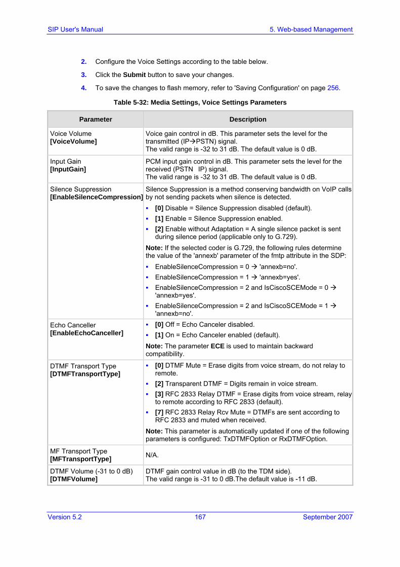
Version 5.2 167 September 2007
SIP User's Manual 5. Web-based Management
2. Configure the Voice Settings according to the table below.
3. Click the Submit button to save your changes.
4. To save the changes to flash memory, refer to 'Saving Configuration' on page 256.
Table 5-32: Media Settings, Voice Settings Parameters
Parameter Description
Voice Volume [VoiceVolume]
Voice gain control in dB. This parameter sets the level for the transmitted (IP PSTN) signal. The valid range is -32 to 31 dB. The default value is 0 dB.
Input Gain [InputGain]
PCM input gain control in dB. This parameter sets the level for the received (PSTN�IP) signal. The valid range is -32 to 31 dB. The default value is 0 dB.
Silence Suppression [EnableSilenceCompression]
Silence Suppression is a method conserving bandwidth on VoIP calls by not sending packets when silence is detected. [0] Disable = Silence Suppression disabled (default). [1] Enable = Silence Suppression enabled. [2] Enable without Adaptation = A single silence packet is sent
during silence period (applicable only to G.729). Note: If the selected coder is G.729, the following rules determine the value of the 'annexb' parameter of the fmtp attribute in the SDP: EnableSilenceCompression = 0 'annexb=no'. EnableSilenceCompression = 1 'annexb=yes'. EnableSilenceCompression = 2 and IsCiscoSCEMode = 0
'annexb=yes'. EnableSilenceCompression = 2 and IsCiscoSCEMode = 1
'annexb=no'.
Echo Canceller [EnableEchoCanceller]
[0] Off = Echo Canceler disabled. [1] On = Echo Canceler enabled (default).
Note: The parameter ECE is used to maintain backward compatibility.
DTMF Transport Type [DTMFTransportType]
[0] DTMF Mute = Erase digits from voice stream, do not relay to remote.
[2] Transparent DTMF = Digits remain in voice stream. [3] RFC 2833 Relay DTMF = Erase digits from voice stream, relay
to remote according to RFC 2833 (default). [7] RFC 2833 Relay Rcv Mute = DTMFs are sent according to
RFC 2833 and muted when received. Note: This parameter is automatically updated if one of the following parameters is configured: TxDTMFOption or RxDTMFOption.
MF Transport Type [MFTransportType] N/A.
DTMF Volume (-31 to 0 dB) [DTMFVolume]
DTMF gain control value in dB (to the TDM side). The valid range is -31 to 0 dB.The default value is -11 dB.

SIP User's Manual 168 Document #: LTRT-68806
Mediant 2000 & TP-1610 & TP-260/UNI
Table 5-32: Media Settings, Voice Settings Parameters
Parameter Description
CAS Transport Type [CASTransportType]
[0] CAS Events Only = Disable CAS relay (default). [1] CAS RFC2833 Relay = Enable CAS relay mode using RFC
2833. The CAS relay mode can be used with the TDM tunneling feature to enable tunneling over IP for both voice and CAS signaling bearers.
DTMF Generation Twist [DTMFGenerationTwist]
Defines a delta (in dB) between the high and low frequency components in the DTMF signal. Positive decibel values cause the higher frequency component to be stronger than the lower one. Negative values cause the opposite effect. For any parameter value, both components change so that their average is constant. The range is -10 to 10. The default value is 0.
5.7.2 Configuring the Fax / Modem / CID Settings The 'Fax / Modem / CID Settings' screen is used for configuring fax, modem, and Caller ID (CID) parameters.
To configure the Fax, Modem, and CID Settings parameters, take these 4 steps:
1. Open the 'Fax / Modem / CID Settings' screen (Advanced Configuration menu > Media Settings > Fax / Modem / CID Settings option).
Figure 5-34: Fax / Modem / CID Settings Screen

Version 5.2 169 September 2007
SIP User's Manual 5. Web-based Management
2. Configure the Fax / Modem / CID Settings according to the table below.
3. Click the Submit button to save your changes.
4. To save the changes to flash memory, refer to 'Saving Configuration' on page 256.
Table 5-33: Media Settings -- Fax/Modem/CID Parameters
Parameter Description
Fax Transport Mode [FaxTransportMode]
Fax Transport Mode that the gateway uses. [0] Disable = transparent mode. [1] T.38 Relay = (default). [2] Bypass. [3] Events Only.
Note: If parameter IsFaxUsed = 1, then FaxTransportMode is always set to 1 (T.38 relay).
Caller ID Transport Type [CallerIDTransportType]
Defines the Caller ID Transport type. [0] Disable = Disable [1] Relay = Relay [3] Mute = Mute
V.21 Modem Transport Type [V21ModemTransportType]
V.21 Modem Transport Type that the gateway uses. [0] Disable = Disable (Transparent) -- default [1] Enable Relay = N/A [2] Enable Bypass. [3] Events Only = Transparent with Events.
V.22 Modem Transport Type [V22ModemTransportType]
V.22 Modem Transport Type that the gateway uses. [0] Disable = Disable (Transparent) [1] Enable Relay = N/A [2] Enable Bypass = (default) [3] Events Only = Transparent with Events
V.23 Modem Transport Type [V23ModemTransportType]
V.23 Modem Transport Type that the gateway uses. [0] Disable = Disable (Transparent) [1] Enable Relay = N/A [2] Enable Bypass = (default) [3] Events Only = Transparent with Events
V.32 Modem Transport Type [V32ModemTransportType]
V.32 Modem Transport Type that the gateway uses. [0] Disable = Disable (Transparent) [1] Enable Relay = N/A [2] Enable Bypass = (default) [3] Events Only = Transparent with Events
Note: This option applies to V.32 and V.32bis modems.

SIP User's Manual 170 Document #: LTRT-68806
Mediant 2000 & TP-1610 & TP-260/UNI
Table 5-33: Media Settings -- Fax/Modem/CID Parameters
Parameter Description
V.34 Modem Transport Type [V34ModemTransportType]
V.90 / V.34 Modem Transport Type that the gateway uses. [0] Disable = Disable (Transparent) [1] Enable Relay = N/A [2] Enable Bypass = (default) [3] Events Only = Transparent with Events
Fax Relay Redundancy Depth [FaxRelayRedundancyDepth]
Number of times that each fax relay payload is retransmitted to the network. This parameter is applicable only to non-V.21 packets. The valid range is 0 to 2, where 0 is no redundancy, 1 is one packet redundancy, and 2 is two packet redundancy. The default value is 0.
Fax Relay Enhanced Redundancy Depth [FaxRelayEnhancedRedundancyDepth]
Number of times that control packets are retransmitted when using the T.38 standard. The valid range is 0 to 4. The default value is 0.
Fax Relay ECM Enable [FaxRelayECMEnable]
[0] Disable = Error Correction Mode (ECM) mode is not used during fax relay.
[1] Enable = ECM mode is used during fax relay (default).
Fax Relay Max Rate (bps) [FaxRelayMaxRate]
Maximum rate (in bps), at which fax relay messages are transmitted (outgoing calls). [0] 2400 = 2.4 kbps. [1] 4800 = 4.8 kbps. [2] 7200 = 7.2 kbps. [3] 9600 = 9.6 kbps. [4] 12000 = 12.0 kbps. [5] 14400 = 14.4 kbps (default).
Note: The rate is negotiated between the sides, i.e., the gateway adapts to the capabilities of the remote side.
Fax/Modem Bypass Coder Type [FaxModemBypassCoderType]
Coder the gateway uses when performing fax/modem bypass. Usually, high-bit-rate coders such as G.711 should be used. [0] G.711Alaw= G.711 A-law 64 (default). [1] G.711Mulaw = G.711 µ-law.
Fax/Modem Bypass Packing Factor [FaxModemBypassM]
Number of (20 msec) coder payloads that are used to generate a fax/modem bypass packet. The valid range is 1, 2 or 3 coder payloads. The default value is 1 coder payload.

Version 5.2 171 September 2007
SIP User's Manual 5. Web-based Management
Table 5-33: Media Settings -- Fax/Modem/CID Parameters
Parameter Description
CNG Detector Mode [CNGDetectorMode]
[0] Disable = The originating gateway doesn’t detect CNG; the CNG signal passes transparently to the remote side (default).
[1] Relay = CNG is detected on the originating side. CNG packets are sent to the remote side according to T.38 (if IsFaxUsed = 1) and the fax session is started. A Re-INVITE message isn’t sent and the fax session starts by the terminating gateway. This option is useful (for example) when the originating gateway is located behind a firewall that blocks incoming T.38 packets on ports that have not yet received T.38 packets from the internal network (i.e., originating gateway).
[2] Events Only = CNG is detected on the originating side. The CNG signal passes transparently to the remote side and a fax session is started by the originating side using Re-INVITE message. Usually, T.38 fax session starts when the ‘preamble’ signal is detected by the answering side. Some SIP gatewaya don’t support the detection of this fax signal on the answering side, thus, for these cases it is possible to configure the gateway to start the T.38 fax session when the CNG tone is detected by the originating side. However, this mode is not recommended.

SIP User's Manual 172 Document #: LTRT-68806
Mediant 2000 & TP-1610 & TP-260/UNI
5.7.3 Configuring the RTP / RTCP Settings The 'RTP / RTCP Settings' screen is used for configuring RTP/RTCP parameters.
To configure the RTP / RTCP Settings parameters, take these 4 steps:
1. Open the 'RTP / RTCP Settings' screen (Advanced Configuration menu > Media Settings > RTP / RTCP Settings option).
2. Configure the RTP / RTCP Settings according to the table below.
3. Click the Submit button to save your changes.
4. To save the changes to flash memory, refer to 'Saving Configuration' on page 256.

Version 5.2 173 September 2007
SIP User's Manual 5. Web-based Management
Table 5-34: Media Settings, RTP / RTCP Parameters
Parameter Description
Dynamic Jitter Buffer Minimum Delay [DJBufMinDelay]
Minimum delay for the Dynamic Jitter Buffer. The valid range is 0 to 150 milliseconds. The default delay is 10 milliseconds. Note: For more information on the Jitter Buffer, refer to 'Dynamic Jitter Buffer Operation' on page 350.
Dynamic Jitter Buffer Optimization Factor [DJBufOptFactor]
Dynamic Jitter Buffer frame error / delay optimization factor. The valid range is 0 to 13. The default factor is 10. Notes: Set to 13 for data (fax and modem) calls. For more information on the Jitter Buffer, refer to 'Dynamic
Jitter Buffer Operation' on page 350.
RTP Redundancy Depth [RTPRedundancyDepth]
[0] 0 = Disable the generation of redundant packets (default). [1] 1 = Enable the generation of RFC 2198 redundancy
packets.
Packing Factor [RTPPackingFactor]
N/A. Controlled internally by the gateway according to the selected coder.
Basic RTP Packet Interval [BasicRTPPacketInterval]
N/A. Controlled internally by the gateway according to the selected coder. Note: This parameter should not be used. Use the 'Coders' screen under 'Protocol Definition' instead.
RTP Directional Control [RTPDirectionControl]
N/A. Controlled internally by the gateway according to the selected coder.
RFC 2833 TX Payload Type [RFC2833TxPayloadType]
N/A. Use the ini file parameter RFC2833PayloadType instead.
RFC 2833 RX Payload Type [RFC2833RxPayloadType]
N/A. Use the ini file parameter RFC2833PayloadType instead.
RFC 2198 Payload Type [RFC2198PayloadType]
RTP redundancy packet payload type, according to RFC 2198. The range is 96-127. The default is 104. Applicable if RTP Redundancy Depth = 1.
Fax Bypass Payload Type [FaxBypassPayloadType]
Determines the fax bypass RTP dynamic payload type. The valid range is 96 to 120. The default value is 102.
Enable RFC 3389 CN Payload Type [EnableStandardSIDPayloadType]
Determines whether Silence Indicator (SID) packets that are sent and received are according to RFC 3389. [0] Disable = G.711 SID packets are sent in a proprietary
method (default). [1] Enable = SID (comfort noise) packets are sent with the RTP
SID payload type according to RFC 3389. Applicable to G.711 and G.726 coders.

SIP User's Manual 174 Document #: LTRT-68806
Mediant 2000 & TP-1610 & TP-260/UNI
Table 5-34: Media Settings, RTP / RTCP Parameters
Parameter Description
Comfort Noise Generation Negotiation [ComfortNoiseNegotiation]
Enables negotiation and usage of Comfort Noise (CN). [0] Disable = Disable (default). [1] Enable = Enable Comfort Noise negotiation
The use of CN is indicated by including a payload type for CN on the media description line of the SDP. The gateway can use CN with a codec whose RTP timestamp clock rate is 8,000 Hz (G.711/G.726). The static payload type 13 is used. The use of CN is negotiated between sides; therefore, if the remote side doesn't support CN, it is not used. Note: Silence Suppression must be enabled to generate CN.
RTP Base UDP Port [BaseUDPPort]
Lower boundary of UDP port used for RTP, RTCP (Real-Time Control Protocol) (RTP port + 1) and T.38 (RTP port + 2). The upper boundary is the Base UDP Port + 10 * (number of gateway's channels). The range of possible UDP ports is 6,000 to 64,000. The default base UDP port is 6000. For example: If the Base UDP Port is set to 6000 (the default) then: 1) The first channel uses the following ports: RTP 6000, RTCP 6001 and T.38 6002, 2) the second channel uses: RTP 6010, RTCP 6011 and T.38 6012, etc. Note: If RTP Base UDP Port is not a factor of 10, the following message is generated: 'invalid local RTP port'. For detailed information on the default RTP/RTCP/T.38 port allocation, refer to the SIP Series Reference Manual.
Remote RTP Base UDP Port [RemoteBaseUDPPort]
Determines the lower boundary of UDP ports used for RTP, RTCP and T.38 by a remote gateway. If this parameter is set to a non-zero value, ThroughPacket™ is enabled. Note that the value of RemoteBaseUDPPort on the local gateway must equal the value of BaseUDPPort of the remote gateway. The gateway uses these parameters to identify and distribute the payloads from the received multiplexed IP packet to the relevant channels. The valid range is the range of possible UDP ports: 6,000 to 64,000. The default value is 0 (ThroughPacket is disabled). For detailed information on ThroughPacket, refer to 'RTP Multiplexing (ThroughPacket) on page 349. Notes: To enable ThroughPacket the parameters
L1L1ComplexTxUDPPort and L1L1ComplexRxUDPPort must be set to a non-zero value.
When VLANs are implemented, the ThroughPacket mechanism is not supported.
RTP Multiplexing Local UDP Port [L1L1ComplexTxUDPPort]
Determines the local UDP port used for outgoing multiplexed RTP packets (applies to the ThroughPacket™ mechanism). The valid range is the range of possible UDP ports: 6,000 to 64,000. The default value is 0 (ThroughPacket is disabled). This parameter cannot be changed on-the-fly and requires a gateway reset.

Version 5.2 175 September 2007
SIP User's Manual 5. Web-based Management
Table 5-34: Media Settings, RTP / RTCP Parameters
Parameter Description
RTP Multiplexing Remote UDP Port [L1L1ComplexRxUDPPort]
Determines the remote UDP port the multiplexed RTP packets are sent to, and the local UDP port used for incoming multiplexed RTP packets (applies to the ThroughPacket™ mechanism). The valid range is the range of possible UDP ports: 6,000 to 64,000. The default value is 0 (ThroughPacket is disabled). This parameter cannot be changed on-the-fly and requires a gateway reset. Note: All gateways that participate in the same ThroughPacket session must use the same L1L1ComplexRxUDPPort.
RTCP XR Settings (For a detailed description of RTCP-XR reports, refer to the SIP Series Reference Manual)
Enable RTCP XR [VQMonEnable]
Enables voice quality monitoring and RTCP Extended Reports (RTCP-XR). [0] Disable = Disable (default) [1] Enable = Enables
RTCP XR Report Mode [RTCPXRReportMode]
Determines whether or not RTCP-XR reports are sent to the Event State Compositor (ESC) and if so, defines the interval in which they are sent. [0] Disable = RTCP-XR reports are not sent to the ESC
(default) [1] End Call = RTCP-XR reports are sent to the ESC at the end
of each call. [2] End Call & Periodic = RTCP-XR reports are sent to the ESC
at the end of each call and periodically according to the parameter RTCPInterval.
RTCP XR Packet Interval [RTCPInterval]
Defines the time interval (in msec) between adjacent RTCP reports. The interval range is 0 to 65,535. The default interval is 5,000.
Disable RTCP XR Interval Randomization [DisableRTCPRandomize]
Controls whether RTCP report intervals are randomized or whether each report interval accords exactly to the parameter RTCPInterval. [0] Disable = Randomize (default) [1] Enable = No Randomize
RTCP XR Collection Server [RTCPXREscIP]
IP address of the Event State Compositor (ESC). The gateway sends RTCP-XR reports using PUBLISH messages to this server. The address can be configured as a numerical IP address or as a domain name.

SIP User's Manual 176 Document #: LTRT-68806
Mediant 2000 & TP-1610 & TP-260/UNI
5.7.4 Configuring the IPmedia Settings The 'IPmedia Settings' screen is used for configuring the IPmedia server parameters.
To configure the IPmedia parameters, take these 4 steps:
1. Open the 'IPmedia Parameters' screen (Advanced Configuration menu > Media Settings > IPmedia Settings option).
Figure 5-35: IPmedia Settings Screen
2. Configure the media server parameters according to the table below.
3. Click the Submit button to save your changes.
4. To save the changes to flash memory, refer to 'Saving Configuration' on page 256.

Version 5.2 177 September 2007
SIP User's Manual 5. Web-based Management
Table 5-35: Media Server Parameters
Parameter Description
Enable Answer Detector [EnableAnswerDetector] N/A.
Answer Detector Activity Delay [AnswerDetectorActivityDelay] N/A.
Answer Detector Silence Time [AnswerDetectorSilenceTime] N/A.
Answer Detector Redirection [AnswerDetectorRedirection] N/A.
Answer Detector Sensitivity [AnswerDetectorSensitivity]
Determines the Answer Detector sensitivity. The range is 0 (most sensitive) to 2 (least sensitive). The default is 0.
Enable Energy Detector [EnableEnergyDetector]
N/A
Energy Detector Quality Factor [EnergyDetectorQualityFactor]
N/A
Energy Detector Threshold [EnergyDetectorThreshold]
N/A
Enable Pattern Detector [EnablePatternDetector]
Enables or disables the activation of the Pattern Detector (PD). Valid options include: [0] Disable = Disable (default) [1] Enable = Enable
5.7.5 Configuring the General Media Settings
To configure the General Media Settings parameters, take these 4 steps:
1. Open the 'General Media Settings' screen (Advanced Configuration menu > Media Settings > General Media Settings option).
Figure 5-36: General Media Settings Screen
2. Configure the General Media Settings according to the table below.
3. Click the Submit button to save your changes.
4. To save the changes to flash memory, refer to 'Saving Configuration' on page 256.
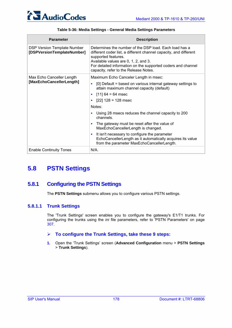
SIP User's Manual 178 Document #: LTRT-68806
Mediant 2000 & TP-1610 & TP-260/UNI
Table 5-36: Media Settings - General Media Settings Parameters
Parameter Description
DSP Version Template Number [DSPVersionTemplateNumber]
Determines the number of the DSP load. Each load has a different coder list, a different channel capacity, and different supported features. Available values are 0, 1, 2, and 3. For detailed information on the supported coders and channel capacity, refer to the Release Notes.
Max Echo Canceller Length [MaxEchoCancellerLength]
Maximum Echo Canceler Length in msec: [0] Default = based on various internal gateway settings to
attain maximum channel capacity (default) [11] 64 = 64 msec [22] 128 = 128 msec
Notes: Using 28 msecs reduces the channel capacity to 200
channels. The gateway must be reset after the value of
MaxEchoCancellerLength is changed. It isn't necessary to configure the parameter
EchoCancellerLength as it automatically acquires its value from the parameter MaxEchoCancellerLength.
Enable Continuity Tones N/A.
5.8 PSTN Settings
5.8.1 Configuring the PSTN Settings The PSTN Settings submenu allows you to configure various PSTN settings.
5.8.1.1 Trunk Settings
The 'Trunk Settings' screen enables you to configure the gateway's E1/T1 trunks. For configuring the trunks using the ini file parameters, refer to 'PSTN Parameters' on page 307.
To configure the Trunk Settings, take these 9 steps:
1. Open the ‘Trunk Settings’ screen (Advanced Configuration menu > PSTN Settings > Trunk Settings).

Version 5.2 179 September 2007
SIP User's Manual 5. Web-based Management

SIP User's Manual 180 Document #: LTRT-68806
Mediant 2000 & TP-1610 & TP-260/UNI
Initially, the screen appears with the parameter fields grayed (indicating read-only), and the Stop Trunk button is displayed at the bottom of the screen (indicating that the trunk is currently active).
The Trunk Status icons display the current status of the trunk:
• Grey: disabled
• Green: active
• Yellow: RAI alarm
• Red: LOS / LOF alarm
• Blue: AIS alarm
• Orange: D-channel alarm (ISDN only)
2. Select the trunk you want to configure, by clicking the Trunk Status icon pertaining to the trunk. The read-only ‘Trunk ID’ field displays the trunk number that you selected. The parameters displayed in the screen pertain to the selected trunk only.
3. Click the Stop Trunk button (unless modifying a Dial Plan -- refer to note below); the trunk is stopped. This is indicated by the following:
• The ‘Trunk Configuration State’ read-only field displays ‘Inactive’.
• The Stop Trunk button is replaced by the Apply Trunk Settings button. (When all trunks are stopped, the Apply to all Trunks button also appears.)
• The parameters are no longer grayed and can now be modified.
Notes:
• When CAS is selected as the Protocol Type (refer to Step 4 below), you can apply a dial plan (in the Dial plan' field) without stopping the trunk. Modifying the Dial Plan causes the button located at the bottom of the screen to become Apply Dial Plan.
• If the trunk protocol type is CAS (displayed in the 'Protocol Type' field), you can apply or modify a dial plan (in the 'Dial Plan' field) without stopping the trunk. Modifying the dial plan replaces the Stop Trunk with the Apply Dial Plan button.
• If the trunk can’t be stopped because it provides the gateway’s clock (assuming the gateway is synchronized with the E1/T1 clock), assign a different E1/T1 trunk to provide the gateway’s clock or enable ‘TDM Bus PSTN Auto Clock’ in the 'TDM Bus Settings' screen. To assign a different E1/T1 trunk that provides the gateway’s clock, access the ‘TDM Bus Setting’ screen ('Configuring the TDM Bus Settings'on page 195) and change the ‘TDM Bus Local Reference’ number to any other trunk number (this operation can be performed on-the-fly).

Version 5.2 181 September 2007
SIP User's Manual 5. Web-based Management
4. From the ‘Protocol Type’ drop-down list, select the required protocol.
Notes:
• Different trunks can be defined with different protocols (CAS or ISDN variants) on the same gateway (subject to the constraints in the gateway's Release Notes).
• When modifying the ‘Protocol Type’ field, the menu is automatically updated according to the selected protocol (ISDN, CAS, or Transparent). Additional parameters are appropriate to the selected protocol type.
5. Modify the relevant trunk configuration parameters according to your requirements.
6. To configure the different behavior bits: either enter the exact hexadecimal value of the bits in the field to the right of the relevant behavior parameter, or directly configure each bit field by completing the following steps:
a. Click the arrow button (-->) to the right of the relevant behavior parameter; a new window appears.
b. Modify each bit field according to your requirements. c. Click the Submit button to save your changes.
7. After modifying the parameters:
• To apply the changes to the selected trunk only, click the Apply Trunk Settings button.
• To apply the changes to all the trunks, click the Apply to all Trunks button.
8. The screen is refreshed; parameters become read-only (indicated by being grayed). The Stop Trunk button replaces the Apply Trunk Settings button.
9. To save the changes to flash memory, refer to 'Saving Configuration' on page 256.
Note: Some parameter configuration options require device reset; when this is the case, the Embedded Web Server prompts the user.
10. To reset the gateway, refer to 'Resetting the Gateway' on page 257.

SIP User's Manual 182 Document #: LTRT-68806
Mediant 2000 & TP-1610 & TP-260/UNI
Table 5-37: E1/T1/J1 Configuration Parameters
ini File Field Name Web Parameter Name Valid Range and Description
Protocol Type [ProtocolType]
Sets the PSTN protocol to be used for this trunk. [1] E1 EURO ISDN [2] T1 CAS [3] T1 RAW CAS [4] T1 TRANSPARENT [5] E1 TRANSPARENT 31 [6] E1 TRANSPARENT 30 [7] E1 MFCR2 [8] E1 CAS [9] E1 RAW CAS [10] T1 NI2 ISDN [11] T1 4ESS ISDN [12] T1 5ESS 9 ISDN [13] T1 5ESS 10 ISDN [14] T1 DMS100 ISDN [15] J1 TRANSPARENT [16] T1 NTT ISDN = Japan - Nippon Telegraph [17] E1 AUSTEL ISDN = Australian Telecom [18] T1 HKT ISDN = Hong Kong - HKT [19] E1 KOR ISDN = Korean operator [20] T1 HKT ISDN = Hong Kong - HKT over T1 [21] E1 QSIG [23] T1 QSIG [31] E1 FRENCH VN3 ISDN [35] T1 DMS100 Meridian ISDN [40] E1 NI2 ISDN [41] E1 CAS R15
Note: The gateway simultaneously supports different variants of CAS and PRI protocols on different E1/T1 spans (no more than four simultaneous PRI variants).
Clock Master [ClockMaster]
Determines the Tx clock source of the E1/T1 line. [0] Recovered = Generate the clock according to the Rx of the E1/T1
line (default). [1] Generated = Generate the clock according to the internal TDM
bus. For detailed information on configuring the gateway's clock settings, refer to 'Clock Settings' on page 381. Note: The source of the internal TDM bus clock is determined by the parameter TDMBusClockSource.

Version 5.2 183 September 2007
SIP User's Manual 5. Web-based Management
Table 5-37: E1/T1/J1 Configuration Parameters
ini File Field Name Web Parameter Name Valid Range and Description
Auto Clock Trunk Priority [AutoClockTrunkPriority]
Defines the trunk priority for auto-clock fallback (per trunk parameter). 0 to 99 = priority (0 is the highest = default). 100 = the SW never performs a fallback to that trunk (usually used to
mark un-trusted source of clock). Note: Fallback is enabled when the TDMBusPSTNAutoClockEnable parameter is set to 1.
Line Code [LineCode]
Use to select B8ZS or AMI for T1 spans, and HDB3 or AMI for E1 spans. [0] B8ZS = use B8ZS line code (for T1 trunks only) default. [1] AMI = use AMI line code. [2] HDB3 = use HDB3 line code (for E1 trunks only).
Line Build Out Loss [LineBuildOut.Loss]
Selects the line build out loss to be used for T1 trunks. [0] 0 dB (default) [1] -7.5 dB [2] -15 dB [3] -22.5 dB
Note: This parameter is not applicable for E1 trunks.
Trace Level [TraceLevel]
Defines the trace level: [0] No Trace (default) [1] Full ISDN Trace [2] Layer 3 ISDN Trace [3] Only ISDN Q.931 Messages Trace [4] Layer 3 ISDN No Duplication Trace
Framing Method [FramingMethod]
Selects the physical framing method used for the trunk. [0] = default according to protocol type E1 or T1. E1 default = E1
CRC4 MultiFrame Format extended G.706B (as c); T1 default = T1 Extended SuperFrame with CRC6 (as D).
[1] = T1 SuperFrame Format (as B). [a] = E1 DoubleFrame Format [b] = E1 CRC4 MultiFrame Format [c] = E1 CRC4 MultiFrame Format extended G.706B [A] = T1 4-Frame multiframe. [B] = T1 12-Frame multiframe (D4). [C] = T1 Extended SuperFrame without CRC6 [D] = T1 Extended SuperFrame with CRC6 [E] = T1 72-Frame multiframe (SLC96) [F] = J1 Extended SuperFrame with CRC6 (Japan)

SIP User's Manual 184 Document #: LTRT-68806
Mediant 2000 & TP-1610 & TP-260/UNI
Table 5-37: E1/T1/J1 Configuration Parameters
ini File Field Name Web Parameter Name Valid Range and Description
ISDN Configuration Parameters
ISDN Termination Side [TerminationSide]
Selects the ISDN termination side. Applicable only to ISDN protocols. [0] User side = ISDN User Termination Side (TE) (default) [1] Network side = ISDN Network Termination Side (NT)
Note: select 'User side' when the PSTN or PBX side is configured as 'Network side', and vice-versa. If you don't know the gateway ISDN termination side, choose 'User side' and refer to the 'Status & Diagnostics > Channel Status' screen. If the D-channel alarm is indicated, choose 'Network Side'.
NFAS Group Number [NFASGroupNumber_x]
Indicates the NFAS group number (NFAS member) for the selected trunk. 'x' identifies the Trunk ID. 0 = Non NFAS trunk (default) 1 to 4 = NFAS group number
Trunks that belong to the same NFAS group have the same number. With ISDN Non-Facility Associated Signaling you can use single D-channel to control multiple PRI interfaces. Applicable only to T1 ISDN protocols.
NFAS Interface ID [ISDNNFASInterfaceID_x]
Defines a different Interface ID for each T1 trunk. The valid range is 0 to 100. The default interface ID equals to the trunk's ID. 'x' identifies the trunk ID. Note: To set the NFAS interface ID, configure ISDNIBehavior_x to include '512' feature per T1 trunk.
D-channel Configuration [DChConfig_x]
Defines primary, backup (optional), and B-channels only trunks. 'x' identifies the Trunk ID. [0] PRIMARY= Primary Trunk (default) [1] BACKUP = Backup Trunk [2] NFAS = NFAS Trunk
Primary trunk contains D-channel that is used for signaling. Backup trunk contains backup D-channel that is used if the primary D-channel fails. The other NFAS trunks contain only 24 B-channels, without a signaling D-channel. Note: Applicable only to T1 ISDN protocols.

Version 5.2 185 September 2007
SIP User's Manual 5. Web-based Management
Table 5-37: E1/T1/J1 Configuration Parameters
ini File Field Name Web Parameter Name Valid Range and Description
Enable Receiving of Overlap Dialing [ISDNRxOverlap_x]
Enable / disable Rx ISDN overlap per trunk ID. [0] Disable = Disabled (default). [1] Enable = Enabled.
Notes: If enabled, the gateway receives ISDN called number that is sent in
the 'Overlap' mode. The SETUP message to IP is sent only after the number (including
the 'Sending Complete' Info Element) was fully received (via SETUP and/or subsequent INFO Q.931 messages).
The 'MaxDigits' parameter can be used to limit the length of the collected number for gateway ISDN overlap dialing (if sending complete is not received).
If a digit map pattern is defined (DigitMapping), the gateway collects digits until a match is found (e.g., for closed numbering schemes) or until a timer expires (e.g., for open numbering schemes). If a match is found (or the timer expires), the digit collection process is terminated even if Sending Complete wasn't received.
Local ISDN Ringback Tone Source [LocalISDNRBSource_ID]
Determines whether Ringback tone is played to the ISDN by the PBX / PSTN or by the gateway, where ID is the Trunk number (0-0-7). [0] PBX = PBX / PSTN (default). [1] Gateway.
This parameter is applicable to ISDN protocols. It is used simultaneously with the parameter 'PlayRBTone2Trunk'.
Progress Indicator to ISDN [ProgressIndicator2ISDN_ID]
Progress indicator (PI) to ISDN, where ID is the Trunk number (0-7). [-1] Not Configured = The PI in ISDN messages is set according to
the 'Play Ringback to Tel' parameter (default). [0] No PI = PI is not sent to ISDN. [1] PI = 1; [8] PI = 8: The PI value is sent to PSTN in
Q.931/Proceeding and Alerting messages. Typically, the PSTN/PBX cuts through the audio channel without playing local Ringback tone, enabling the originating party to hear remote Call Progress Tones or network announcements.
Set PI in Rx Disconnect Message [PIForDisconnectMsg_ID]
Defines the gateway's behavior when a Disconnect message is received from the ISDN before a Connect message is received. Where ID is the Trunk number (0-7). [-1] Not Configured = Sends a 183 message according to the
received progress indicator (PI) in the ISDN Disconnect message. If PI = 1 or 8, the gateway sends a 183 response, enabling the PSTN to play a voice announcement to the IP side. If there isn't a PI in the Disconnect message, the call is released (default).
[0] No PI = Don't send a 183 message to IP. The call is released. [1] PI = 1; [8] PI = 8: Sends a 183 message to IP.

SIP User's Manual 186 Document #: LTRT-68806
Mediant 2000 & TP-1610 & TP-260/UNI
Table 5-37: E1/T1/J1 Configuration Parameters
ini File Field Name Web Parameter Name Valid Range and Description
ISDN Transfer Capabilities [ISDNTransferCapability_ID]
Defines the IP-to-ISDN Transfer Capability of the Bearer Capability IE in ISDN Setup messages. ID is the Trunk number. [0] Audio 3.1 = Audio (default). [1] Speech = Speech. [2] Data = Data. Audio 7 = Currently not supported. [-1] Not Configured
Note: If this parameter isn't configured or equals to '-1', Audio 3.1 capability is used.
ISDN Flexible Behavior Parameters ISDN protocol is implemented in different Switches / PBXs by different vendors. Several implementations vary a little from the specification. Therefore, to provide a flexible interface that supports these ISDN variants, the ISDN behavior parameters are used.
Q.931 Layer Response Behavior [ISDNIBehavior]
Bit-field used to determine several behavior options that influence the behaviour of the Q.931 protocol. To select the options, click the arrow button, and then for each required option, select 1 to enable. The default is 0 (i.e., disable).
[1] NO STATUS ON UNKNOWN IE = Q.931 Status message isn't sent if Q.931 received message contains an unknown/unrecognized IE(s). By default, the Status message is sent. This parameter applies only to PRI variants in which sending of Status message is optional.
[2] NO STATUS ON INV OP IE = Q.931 Status message isn't sent if an optional IE with invalid content is received. By default, the Status message is sent. This parameter applies only to PRI variants in which sending of Status message is optional.
[4] ACCEPT UNKNOWN FAC IE = Accepts unknown/unrecognized Facility IE. Otherwise, the Q.931 message that contains the unknown Facility IE is rejected (default). This parameter applies to PRI variants where a complete ASN1 decoding is performed on Facility IE.
[128] SEND USER CONNECT ACK = Connect ACK message is sent in response to received Q.931 Connect. Applicable only to Euro ISDN User side outgoing calls. Otherwise, the Connect ACK is not sent (default).
[512] EXPLICIT INTERFACE ID = Enables to configure T1 NFAS Interface ID (refer to the parameter ISDNNFASInterfaceID_x). Applicable to 4/5ESS, DMS, NI-2 and HKT variants.
[2048] ALWAYS EXPLICIT = Always set the Channel Identification IE to explicit Interface ID, even if the B-channel is on the same trunk as the D-channel. Applicable to 4/5ESS, DMS and NI-2 variants.
[32768] ACCEPT MU LAW =Mu-Law is also accepted in ETSI. [65536] EXPLICIT PRES SCREENING = The calling party number
(octet 3a) is always present even when presentation and screening are at their default. Applicable to ETSI, NI-2 and 5ESS.
[131072] STATUS INCOMPATIBLE STATE = Clears the call on receipt of Q.931 Status with incompatible state. Otherwise, no action is taken (default).

Version 5.2 187 September 2007
SIP User's Manual 5. Web-based Management
Table 5-37: E1/T1/J1 Configuration Parameters
ini File Field Name Web Parameter Name Valid Range and Description
[262144] STATUS ERROR CAUSE = Clear call on receipt of STATUS according to cause value.
[524288] ACCEPT A LAW =A-Law is also accepted in 5ESS. [2097152] RESTART INDICATION
=acEV_PSTN_RESTART_CONFIRM is generated on receipt of a RESTART message.
[4194304] FORCED RESTART =On data link (re)initialization, send RESTART if there is no call.
[2147483648] NS 5ESS NATIONAL = Use the National mode of AT&T 5ESS for B-channel maintenance.
Note: To configure the gateway to support several ISDNIBehavior features, add the individual feature values. For example, to support both [512] and [2048] features, set ISDNIBehavior = 2560 (i.e., 512 + 2048).
Outgoing Calls Behavior [ISDNOutCallsBehavior]
This parameter determines several behaviour options that influence the behaviour of the ISDN Stack outgoing calls. To select options, click the arrow button, and then for each required option, select 1 to enable. The default is 0 (i.e., disable). [2] USER SENDING COMPLETE =When this bit is set, the gateway
doesn't automatically generate the information element ‘Sending-complete’ in the SETUP message. If this bit is not set, the gateway generates it automatically in the SETUP message only.
[16] USE MU LAW = When set, the gateway sends G.711-m-Law in outgoing voice calls. When disabled, the gateway sends G.711-A-Law in outgoing voice calls. (Applicable only to the Korean variant.)
[128] DIAL WITH KEYPAD = When enabled, the gateway uses the KEYPAD IE to store the called number digits instead of the CALLED_NB IE. (Only applicable to the KOR variant (Korean network). Useful for Korean switches that don't accept the CALLED_NB IE.)
[256] STORE CHAN ID IN SETUP =When this bit is set, the gateway forces the sending of a Channel-id IE in an outgoing SETUP message even if it's not required by the standard (i.e., optional), and no Channel-id has been specified in the establishment request. This is useful for improving required compatibility with switches. On BRI lines, the Channel-id IE indicates ‘any channel’. On PRI lines, it indicates an unused channel ID, preferred only.
[572] USE A LAW = When set, the gateway sends G.711 A-Law in outgoing voice calls. When disabled, the gateway sends the default G.711-Law in outgoing voice calls. Applicable to E10 variant.
[1024] = Numbering plan / type for T1 IP-to-Tel calling numbers are defined according to the manipulation tables or according to the RPID header (default). Otherwise, the plan / type for T1 calls are set according to the length of the calling number.
[2048] = When this bit is set, the gateway accepts any IA5 character in the called_nb and calling_nb strings, and isn’t restricted to extended digits only (i.e., 0-9,*,#).
[16384] DLCI REVERSED OPTION = Behavior bit used in the IUA

SIP User's Manual 188 Document #: LTRT-68806
Mediant 2000 & TP-1610 & TP-260/UNI
Table 5-37: E1/T1/J1 Configuration Parameters
ini File Field Name Web Parameter Name Valid Range and Description
interface groups to indicate that the reversed format of the DLCI field must be used.
Note: When using the ini file to configure the gateway to support several ISDNOutCallsBehavior features, add the individual feature values. For example, to support both [2] and [16] features, set ISDNOutCallsBehavior = 18 (i.e., 2 + 16).
Incoming Calls Behavior [ISDNInCallsBehavior]
This is the bit-field used to determine several behavior options that influence how the ISDN Stack INCOMING calls behave. To select the options, click the arrow button, and then for each required option, select 1 to enable. The default is 0 (i.e., disable). [32] DATA CONN RS = Sends a CONNECT (answer) message on
NOT incoming Tel calls. [64] VOICE CONN RS = gateway sends a CONNECT (answer)
message on incoming Tel calls. [2048] CHAN ID IN FIRST RS = Sends Channel ID in the first
response to an incoming Q.931 Call Setup message. Otherwise, the Channel ID is sent only if the gateway requires changing the proposed Channel ID (default).
[8192] CHAN ID IN CALL PROC = Sends Channel ID in a Q.931 Call Proceeding message.
[65536] PROGR IND IN SETUP ACK = Includes Progress Indicator (PI=8) in Setup ACK message if an empty called number is received in an incoming Setup message. Applicable to overlap dialing mode. The parameter also directs the gateway to play a dial tone (for TimeForDialTone), until the next called number digits are received.
[262144] = NI-2 second redirect number. You can select and use (in INVITE messages) the NI-2 second redirect number if two redirect numbers are received in Q.931 Setup for incoming Tel-to-IP calls.
Note: When using the ini file to configure the gateway to support several ISDNInCallsBehavior features, add the individual feature values. For example, to support both [2048] and [65536] features, set ISDNInCallsBehavior = 67584 (i.e., 2048 + 65536).

Version 5.2 189 September 2007
SIP User's Manual 5. Web-based Management
Table 5-37: E1/T1/J1 Configuration Parameters
ini File Field Name Web Parameter Name Valid Range and Description
General Call Control Behavior [ISDNGeneralCCBehavior]
Bit-field used to determine several general CC behavior options. To select the options, click the arrow button, and then for each required option, select 1 to enable. The default is 0 (i.e., disable). [2] = data calls with interworking indication use 64 kbps B-channels
(physical only). [8] REVERSE CHAN ALLOC ALGO = Channel ID allocation
algorithm. [16] = The gateway clears down the call if it receives a NOTIFY
message specifying 'User-Suspended'. A NOTIFY (User-Suspended) message is used by some networks (e.g., in Italy or Denmark) to indicate that the remote user has cleared the call, especially in the case of a long distance voice call.
[32] CHAN ID 16 ALLOWED = Applies only to ETSI E1 lines (30B+D). Enables handling the differences between the newer QSIG standard (ETS 300-172) and other ETSI-based standards (ETS 300-102 and ETS 300-403) in the conversion of B-channel ID values into timeslot values: 1) In 'regular ETSI' standards, the timeslot is identical to the B-channel ID value, and the range for both is 1 to 15 and 17 to 31. The D-channel is identified as channel-id #16 and carried into the timeslot #16. 2) In newer QSIG standards, the channel-id range is 1 to 30, but the timeslot range is still 1 to 15 and 17 to 31. The D-channel is not identified as channel-id #16, but is still carried into the timeslot #16. When this bit is set, the channel ID #16 is considered as a valid B-channel ID, but timeslot values are converted to reflect the range 1 to 15 and 17 to 31. This is the new QSIG mode of operation. When this bit is not set (default), the channel_id #16 is not allowed, as for all ETSI-like standards.
[64] USE T1 PRI = PRI interface type is forced to T1. [128] USE E1 PRI = PRI interface type is forced to E1. [256] START WITH B CHAN OOS = B-channels start in the Out-Of-
Service state (OOS). [512] CHAN ALLOC LOWEST = CC allocates B-channels starting
from the lowest available B-channel id. [1024] CHAN ALLOC HIGHEST = CC allocates B-channels starting
from the highest available B-channel id. Note: When using the ini file to configure the gateway to support several ISDNGeneralCCBehavior features, add the individual feature values. For example, to support both [16] and [32] features, set ISDNGeneralCCBehavior = 48 (i.e., 16 + 32).

SIP User's Manual 190 Document #: LTRT-68806
Mediant 2000 & TP-1610 & TP-260/UNI
Table 5-37: E1/T1/J1 Configuration Parameters
ini File Field Name Web Parameter Name Valid Range and Description
CAS Configuration
CAS Table [CASTableIndex_x]
Defines CAS protocol for each trunk ID from a list of CAS protocols defined by the parameter CASFileName_Y. For example: CASFileName_0 = 'E_M_WinkTable.dat' CASFileName_1 = 'E_M_ImmediateTable.dat' CASTableIndex_0 = 0 CASTableIndex_1 = 0 CASTableIndex_2 = 1 CASTableIndex_3 = 1 Trunks 0 and 1 use the E&M Winkstart CAS protocol, while trunks 2 and 3 use the E&M Immediate Start CAS protocol. Note: For additional CAS table ini file parameters (CASFileName_0, CASFileName_1, CASFileName_7, and CASTablesNum), refer to 'E1/T1 Configuration Parameters' on page 307.
Dial Plan [CasTrunkDialPlanName]
The Dial Plan name that is used on a specific trunk. The range is up to 11 character strings.
Miscellaneous
PSTN Alert Timeout [TrunkPSTNAlertTimeout_ID]
Alert Timeout (ISDN T301 timer) in seconds for outgoing calls to PSTN. This timer is used between the time that SETUP is sent to the Tel side (IP-to-Tel call establishment) and CONNECT is received. If ALERT is received, the timer is restarted. The ID is the trunk number (0 - 7). The range is 1 to 600. The default is 180 seconds.
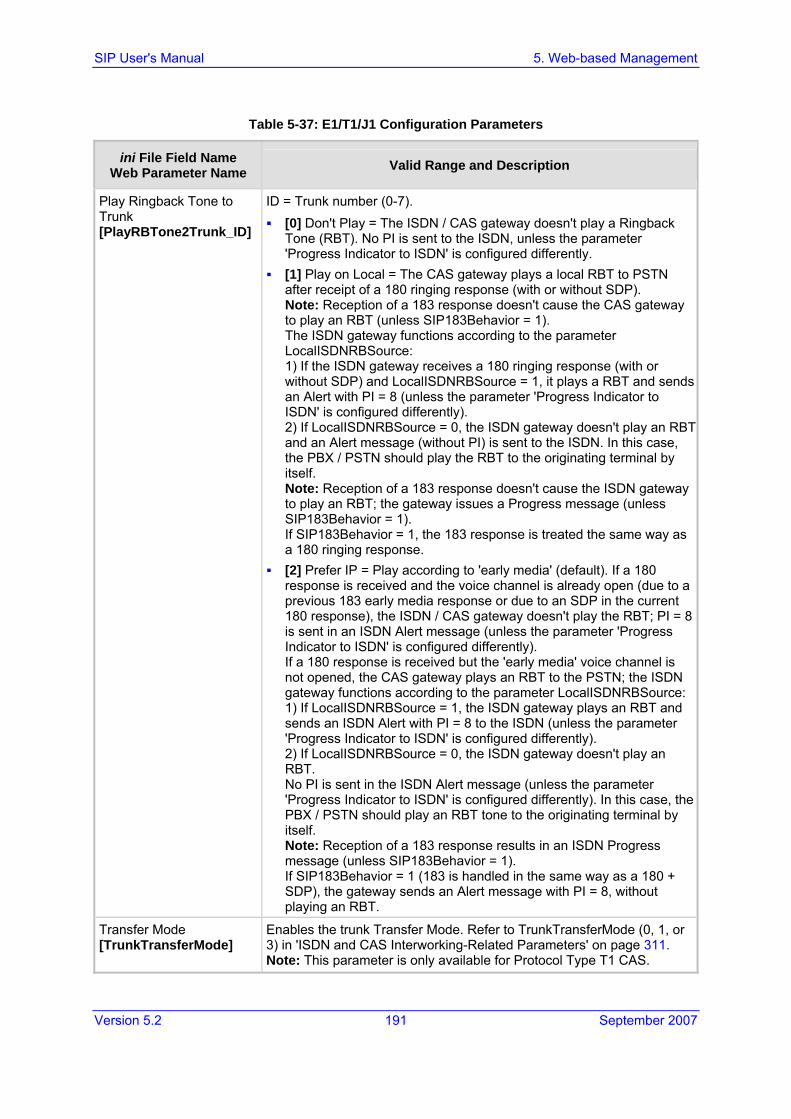
Version 5.2 191 September 2007
SIP User's Manual 5. Web-based Management
Table 5-37: E1/T1/J1 Configuration Parameters
ini File Field Name Web Parameter Name Valid Range and Description
Play Ringback Tone to Trunk [PlayRBTone2Trunk_ID]
ID = Trunk number (0-7). [0] Don't Play = The ISDN / CAS gateway doesn't play a Ringback
Tone (RBT). No PI is sent to the ISDN, unless the parameter 'Progress Indicator to ISDN' is configured differently.
[1] Play on Local = The CAS gateway plays a local RBT to PSTN after receipt of a 180 ringing response (with or without SDP). Note: Reception of a 183 response doesn't cause the CAS gateway to play an RBT (unless SIP183Behavior = 1). The ISDN gateway functions according to the parameter LocalISDNRBSource: 1) If the ISDN gateway receives a 180 ringing response (with or without SDP) and LocalISDNRBSource = 1, it plays a RBT and sends an Alert with PI = 8 (unless the parameter 'Progress Indicator to ISDN' is configured differently). 2) If LocalISDNRBSource = 0, the ISDN gateway doesn't play an RBT and an Alert message (without PI) is sent to the ISDN. In this case, the PBX / PSTN should play the RBT to the originating terminal by itself. Note: Reception of a 183 response doesn't cause the ISDN gateway to play an RBT; the gateway issues a Progress message (unless SIP183Behavior = 1). If SIP183Behavior = 1, the 183 response is treated the same way as a 180 ringing response.
[2] Prefer IP = Play according to 'early media' (default). If a 180 response is received and the voice channel is already open (due to a previous 183 early media response or due to an SDP in the current 180 response), the ISDN / CAS gateway doesn't play the RBT; PI = 8 is sent in an ISDN Alert message (unless the parameter 'Progress Indicator to ISDN' is configured differently). If a 180 response is received but the 'early media' voice channel is not opened, the CAS gateway plays an RBT to the PSTN; the ISDN gateway functions according to the parameter LocalISDNRBSource:1) If LocalISDNRBSource = 1, the ISDN gateway plays an RBT and sends an ISDN Alert with PI = 8 to the ISDN (unless the parameter 'Progress Indicator to ISDN' is configured differently). 2) If LocalISDNRBSource = 0, the ISDN gateway doesn't play an RBT. No PI is sent in the ISDN Alert message (unless the parameter 'Progress Indicator to ISDN' is configured differently). In this case, the PBX / PSTN should play an RBT tone to the originating terminal by itself. Note: Reception of a 183 response results in an ISDN Progress message (unless SIP183Behavior = 1). If SIP183Behavior = 1 (183 is handled in the same way as a 180 + SDP), the gateway sends an Alert message with PI = 8, without playing an RBT.
Transfer Mode [TrunkTransferMode]
Enables the trunk Transfer Mode. Refer to TrunkTransferMode (0, 1, or 3) in 'ISDN and CAS Interworking-Related Parameters' on page 311. Note: This parameter is only available for Protocol Type T1 CAS.

SIP User's Manual 192 Document #: LTRT-68806
Mediant 2000 & TP-1610 & TP-260/UNI
Table 5-37: E1/T1/J1 Configuration Parameters
ini File Field Name Web Parameter Name Valid Range and Description
Enable TBCT [TrunkTransferMode]
Enables the TBCT trunk transfer mode. Refer to TrunkTransferMode (0 and 2) in 'ISDN and CAS Interworking-Related Parameters' on page 311.Note: This parameter is only available for Protocol Type T1 N12 ISDN.
Enable RLT [TrunkTransferMode]
Enables the RLT trunk transfer mode. Refer to TrunkTransferMode (0 and 2) in 'ISDN and CAS Interworking-Related Parameters' on page 311.Note: This parameter is only available for Protocol Type T1 DMS100 ISDN.
Enable Single Step Transfer [TrunkTransferMode]
Enables the Single Step Transfer trunk transfer mode. Refer to TrunkTransferMode (0 and 4) in 'ISDN and CAS Interworking-Related Parameters' on page 311. Note: This parameter is only available for Protocol Type T1 QSIG.
Enable ECT [TrunkTransferMode]
Enables the ECT trunk transfer mode. Refer to TrunkTransferMode (0 and 2) in 'ISDN and CAS Interworking-Related Parameters' on page 311.Note: This parameter is only available for Protocol Type E1 EURO ISDN.
5.8.1.2 CAS State Machines
The 'CAS State Machine Table' screen allows you to modify various timers and other basic parameters to define the initialization of the CAS state machine without changing the state machine itself (no compilation is needed). The change doesn't affect the state machine itself but rather the configuration.
To modify the CAS state machine parameters, take these 6steps:
1. Open the ‘CAS State Machine Table' screen (Advanced Configuration menu > PSTN Settings > CAS State Machine).
Figure 5-37: CAS State Machine Table Screen

Version 5.2 193 September 2007
SIP User's Manual 5. Web-based Management
2. Ensure that the trunk is inactive. The trunk number displayed in the 'Related Trunks' field must be green. If it is red (indicating that the trunk is active), click the trunk number to open the 'Trunk Settings' screen (refer to 'Trunk Settings' on page 178), select the required Trunk number icon, and then click Stop Trunk.
3. In the 'CAS State Machine Table' screen, modify the required parameters according to the table below.
4. Activate the trunk if required in the 'Trunk Settings' screen by clicking the trunk number in the 'Related Trunks' field, and in the 'Trunk Settings' screen (refer to 'Trunk Settings' on page 178), select the required Trunk number icon, and then click Apply Trunk Settings.
5. Click Submit.
6. Reset the gateway and save your settings to the flash memory (refer to 'Resetting the Gateway' on page 257).
Notes:
• It's strongly recommended that you don't modify the default values unless you fully understand the implications of the changes and know the default values. Every change affects the configuration of the state machine parameters and the call process related to the trunk you are using with this state machine.
• You can only modify CAS state machine parameters if the following conditions are met: 1) Trunks are inactive (stopped), i.e., trunk number displayed in green in the 'Related Trunks' field. 2) State machine is not in use or in reset, or when it is not related to any trunk. In case it is related to a trunk, you must delete the trunk or de-activate (Stop) the trunk.
• Field values displaying '-1' indicate CAS default values. In other words, CAS state machine values are used.
• The modification of the CAS state machine occurs at the CAS application initialization only for non-default values (-1).
• For a detailed description of the CAS Protocol table, refer to the SIP Series Reference Manual.
Table 5-38: CAS State Machine Parameters
Parameter Description
Generate Digit On Time [CasStateMachineGenerateDigitOnTime]
Generates digit on-time (in msec). The value must be a positive value. The default value is -1.
Generate Inter Digit Time [CasStateMachineGenerateInterDigitTime]
Generates digit off-time (in msec). The value must be a positive value. The default value is -1.
DTMF Max Detection Time [CasStateMachineDTMFMaxOnDetectionTime]
Detects digit maximum on time (according to DSP detection information event) in msec units. The value must be a positive value. The default value is -1.

SIP User's Manual 194 Document #: LTRT-68806
Mediant 2000 & TP-1610 & TP-260/UNI
Table 5-38: CAS State Machine Parameters
Parameter Description
DTMF Min Detection Time [CasStateMachineDTMFMinOnDetectionTime]
Detects digit minimum on time (according to DSP detection information event) in msec units. The digit time length must be longer than this value to receive a detection. Any number may be used, but the value must be less then CasStateMachineDTMFMaxOnDetectionTime. The value must be a positive value. The default value is -1.
MAX Incoming Address Digits [CasStateMachineMaxNumOfIncomingAddressDigits]
Defines the limitation for the maximum address digits that need to be collected. After reaching this number of digits, the collection of address digits is stopped. The value must be an integer. The default value is -1.
MAX Incoming ANI Digits [CasStateMachineMaxNumOfIncomingANIDigits]
Defines the limitation for the maximum ANI digits that need to be collected. After reaching this number of digits, the collection of ANI digits is stopped. The value must be an integer. The default value is -1.
Collet ANI [CasStateMachineCollectANI]
In some cases, when the state machine handles the ANI collection (not related to MFCR2), you can control the state machine to collect ANI or discard ANI. [0] No = Don't collect ANI. [1] Yes = Collect ANI. [-1] Default = Default value.
Digit Signaling System [CasStateMachineDigitSignalingSystem]
Defines which Signaling System to use in both directions (detection\generation). [0] DTMF = Uses DTMF signaling. [1] MF = Uses MF signaling (default). [-1] Default = Default value.

Version 5.2 195 September 2007
SIP User's Manual 5. Web-based Management
5.8.2 Configuring the TDM Bus Settings
To configure the TDM Bus Settings parameters, take these 5 steps:
1. Open the 'TDM Bus Settings' screen (Advanced Configuration menu > TDM Bus Settings).
Figure 5-38: TDM Bus Settings Screen
2. Configure the TDM Bus Settings parameters.
3. Click the Submit button to save your changes.
4. To save the changes to flash memory, refer to 'Saving Configuration' on page 256.
5. A device reset is required to activate the TDM Bus Settings parameters. To reset the gateway, refer to 'Resetting the Gateway' on page 257.
Note: Usually the 'PCM Law Select' parameter is set to A-law for E1 trunks and to µ-law for T1 trunks.
Refer to 'Clock Settings' on page 381 for information on configuring the 'TDM Bus Clock Source', 'TDM Bus Enable Fallback' and 'TDM Bus PSTN Auto Clock' parameters.
Table 5-39: TDM Bus Settings Parameters
Parameter Description
PCM Law Select [PCMLawSelect]
[1] Alaw = Alaw (default) [3] MuLaw = MuLaw
Usually A-Law is used for E1 spans and µ-Law for T1 and J1 spans.
TDM Bus Type [TDMBusType]
Must be set to 2 (Framers). Note: Applicable only to TP-260.

SIP User's Manual 196 Document #: LTRT-68806
Mediant 2000 & TP-1610 & TP-260/UNI
Table 5-39: TDM Bus Settings Parameters
Parameter Description
Idle PCM Pattern [IdlePCMPattern]
Defines the PCM Pattern that is applied to E1/T1 timeslot (B-channel) when the channel is idle. The range is 0 to 255. The default is set internally according to the Law select 1 (0xFF for Mu-Law; 0x55 for A-law).
Idle ABCD Pattern [IdleABCDPattern]
ABCD (CAS) Pattern to be applied to CAS signaling bus when the channel is idle. Range 0x0 to 0xF. Default is -1 (default pattern = 0000). Note: This is only relevant when using PSTN interface with CAS protocols.
TDM Bus Local Reference [TDMBusLocalReference]
0 to 7 (default = 0). Physical Trunk ID from which the gateway recovers its clock. Note: Applicable only if TDMBusClockSource = 4 and TDMBusPSTNAutoClockEnable = 0.
TDM Bus PSTN Auto Clock [TDMBusPSTNAutoClockEnable]
Enables or disables the PSTN trunk auto-fallback clock feature. [0] Disable = Recovers the clock from the E1/T1 line
defined by the parameter TDMBusLocalReference (default).
[1] Enable = Recovers the clock from any connected synchronized slave E1/T1 line. If this trunk loses its synchronization, the gateway attempts to recover the clock from the next trunk. Note that initially the gateway attempts to recover the clock from the trunk defined by the parameter TDMBusLocalReference.
Note: This parameter is relevant only if TDMBusClockSource = 4.
TDM Bus PSTN Auto Clock Reverting [TDMBusPSTNAutoClockRevertingEnable]
Enables or disables the PSTN trunk auto-fallback reverting feature. If a trunk with a higher priority than the current LocalReference is being synchronized, the bladeLocalReference changes to the new trunk. [0] Disable (default) [1] Enable
Note: The parameter is valid only when the TDMBusPSTNAutoClockEnable parameter is set to 1.
TDM Bus Clock Source [TDMBusClockSource]
[1] Internal = Generate clock from local source (default). [4] Network = Recover clock from PSTN line.
For detailed information on configuring the gateway's clock settings, refer to 'Clock Settings' on page 381.

Version 5.2 197 September 2007
SIP User's Manual 5. Web-based Management
5.9 Security Settings From the Security Settings submenu, you can configure the following:
Web User Accounts (refer to 'Configuring the Web User Accounts' on page 197)
Web & Telnet Access List (refer to 'Configuring the Web and Telnet Access List' on page 199)
Firewall Settings (refer to 'Configuring the Firewall Settings' on page 200)
Certificates (refer to 'Configuring the Certificates' on page 202)
General Security Settings (refer to 'Configuring the General Security Settings' on page 206)
IPSec Table (refer to 'Configuring the IPSec Table' on page 210)
IKE Table (refer to 'Configuring the IKE Table' on page 214)
5.9.1 Configuring the Web User Accounts To prevent unauthorized access to the Embedded Web Server, two user accounts are available, a primary and secondary. Each account is composed of three attributes: username, password, and access level. For detailed information on the user account mechanism, refer to 'User Accounts' on page 58.
It is recommended that you change the default username and password of the account used to access the Embedded Web Server.

SIP User's Manual 198 Document #: LTRT-68806
Mediant 2000 & TP-1610 & TP-260/UNI
To change the Web User Accounts attributes, take these 4 steps:
1. Open the 'Web User Accounts' screen (Advanced Configuration menu > Security Settings > Web User Accounts option).
Figure 5-39: Web User Accounts Screen (for Users with 'Security Administrator' Privileges)
2. To change the access level of the secondary account (the access level of the primary account cannot be changed), from the 'Access Level' drop-down list, select the new access level, and then click Change Access Level; the new access level is applied immediately.
3. To change the username of an account, enter the new username in the field 'User Name', and then click Change User Name; the new username is applied immediately and the 'Enter Network Password' screen appears. Enter the updated username in the 'Enter Network Password' screen. Note that the username can be a maximum of 19 case-sensitive characters.
4. To change the password of an account, enter the current password in the field 'Current Password', the new password in the fields 'New Password' and 'Confirm New Password', and then click Change Password; the new password is applied immediately and the 'Enter Network Password' screen appears. Enter the updated password in the 'Enter Network Password' screen. Note that the password can be a maximum of 19 case-sensitive characters.
Note: A user with a 'Security Administrator' access level can change all attributes for all accounts. Users with an access level other than 'Security Administrator' can only change their own password and username.

Version 5.2 199 September 2007
SIP User's Manual 5. Web-based Management
5.9.2 Configuring the Web and Telnet Access List The 'Web & Telnet Access List' screen is used to define up to ten IP addresses that are permitted to access the gateway's Embedded Web Server and Telnet interfaces. Access from an undefined IP address is denied. If no IP addresses are defined, this security feature is inactive and the gateway can be accessed from any IP address.
The Web and Telnet Access List can also be defined using the ini file parameter WebAccessList_x (refer to 'Web and Telnet Parameters' on page 287).
To add authorized IP addresses for Embedded Web Server and Telnet access, take these 4 steps:
1. Open the 'Web & Telnet Access List' screen (Advanced Configuration menu > Security Settings > Web & Telnet Access List option).
Figure 5-40: Web & Telnet Access List Screen
2. To add an authorized IP address, in the 'New Authorized IP Address' field, enter the required IP address (refer to Note 1 below), and then click Add New Address; the IP address you entered is added as a new entry to the Web & Telnet Access List table.
3. To delete authorized IP addresses, select the Delete Row check box corresponding to the IP addresses that you want to delete (refer to Note 2 below), and then click Delete Selected Addresses; the IP addresses are removed from the table and can no longer access the Web and Telnet interfaces.
4. To save the changes to flash memory, refer to 'Saving Configuration' on page 256.
Notes:
• The first authorized IP address in the list must be your terminal's IP address; otherwise, access from your terminal is denied.
• Delete your terminal's IP address last from the 'Web & Telnet Access List' screen. If it's deleted before the last, access from your terminal is denied after it's deleted.

SIP User's Manual 200 Document #: LTRT-68806
Mediant 2000 & TP-1610 & TP-260/UNI
5.9.3 Configuring the Firewall Settings The gateway accommodates an internal Firewall, allowing the security administrator to define network traffic filtering rules. For detailed information on the internal Firewall, refer to the SIP Series Reference Manual.
To create a new access firewall rule, take these 6 steps:
1. Open the 'Firewall Settings' screen (Advanced Configuration menu > Security Settings > Firewall Settings option).
Figure 5-41: Firewall Settings Screen
2. In the 'New Rule Index' field, enter the index of the access rule that you want to add.
3. Click the Add an Empty Rule button; a new rule appears; alternatively, click the Copy Selected Rule as a New Rule button; a new rule that is an exact copy of the currently selected rule appears.
4. Configure the rule's parameters according to the table below.
5. Click one of the following buttons:
• Apply Rule Settings to save the new rule (the rule isn't active).
• Activate Rule to save the new rule and activate it.
• Delete Rule to delete the rule.
6. To save the changes to flash memory, refer to 'Saving Configuration' on page 256.
To edit a rule, take these 5 steps:
1. Select the radio button of the entry you want to edit.
2. Click the Make Rule Editable button; the rule's fields can now be modified.
3. Modify the fields according to your requirements.
4. Click the Apply Rule Settings button to save the changes.
5. To save the changes to flash memory, refer to 'Saving Configuration' on page 256.
To activate a de-activated rule, take these 2 steps:
1. Select the radio button of the entry you want to activate.
2. Click the Activate Rule button; the rule is active.

Version 5.2 201 September 2007
SIP User's Manual 5. Web-based Management
To de-activate an activated rule, take these 2 steps:
1. Select the radio button of the entry you want to activate.
2. Click the DeActivate Rule button; the rule is de-activated.
To delete a rule, take these 3 steps:
1. Select the radio button of the entry you want to activate.
2. Click the Delete Rule button; the rule is deleted.
3. To save the changes to flash memory, refer to 'Saving Configuration' on page 256.
Table 5-40: Internal Firewall Parameters
Parameter Description
Is Rule Active A read-only field that indicates whether the rule is active or not. Note: After reset all rules are active.
Source IP [AccessList_Source_IP] IP address (or DNS name) of source network, or a specific host.
Mask [AccessList_Net_Mask]
IP network mask. 255.255.255.255 for a single host or the appropriate value for the source IP addresses. The IP address of the sender of the incoming packet is bitwise ANDed with this mask and then compared to the field 'Source IP'.
Local Port Range [AccessList_Start_Port] [AccessList_End_Port]
The destination UDP/TCP ports (on this device) to which packets are sent. The valid range is 0 to 65535. Note: When the protocol type isn't TCP or UDP, the entire range must be provided.
Protocol [AccessList_Protocol]
The protocol type (e.g., UDP, TCP, ICMP, ESP or 'Any'), or the IANA protocol number (in the range of 0 (Any) to 255). Note: The protocol field also accepts the abbreviated strings 'SIP' and 'HTTP'. Specifying these strings implies selection of the TCP or UDP protocols, and the appropriate port numbers as defined on the device.
Packet Size [AccessList_Packet_Size]
Maximum allowed packet size. The valid range is 0 to 65535. Note: When filtering fragmented IP packets, the 'Packet Size' field relates to the overall (reassembled) packet size, not to the size of each fragment.
Byte Rate [AccessList_Byte_Rate] Expected traffic rate (bytes per second).
Burst Bytes [AccessList_Byte_Burst] Tolerance of traffic rate limit (number of bytes).
Action Upon Match [AccessList_Allow_Type] Action upon match (Allow or Block).
Match Count [AccessList_MatchCount]
A read-only field that provides the number of packets accepted / rejected by a specific rule.

SIP User's Manual 202 Document #: LTRT-68806
Mediant 2000 & TP-1610 & TP-260/UNI
5.9.4 Configuring the Certificates The 'Certificates' screen is used to replace the server (refer to 'Server Certificate Replacement' on page 202) and client (refer to 'Client Certificates' on page 203) certificates and to update the private key (using HTTPSPkeyFileName, as described in the SIP Series Reference Manual).
5.9.4.1 Server Certificate Replacement
The gateway is supplied with a working SSL configuration consisting of a unique self-signed server certificate. If an organizational Public Key Infrastructure (PKI) is used, you may wish to replace this certificate with one provided by your security administrator.
To replace the gateway self-signed certificate, take these 8 steps:
1. Your network administrator should allocate a unique DNS name for the gateway (e.g., dns_name.corp.customer.com). This name is used to access the device, and should therefore be listed in the server certificate.
2. Open the ‘Certificates Signing Request' screen (Advanced Configuration menu > Security Settings submenu > Certificates option).
Figure 5-42: Certificates Signing Request Screen

Version 5.2 203 September 2007
SIP User's Manual 5. Web-based Management
3. In the 'Subject Name' field, enter the DNS name, and then click Generate CSR. A textual certificate signing request, that contains the SSL device identifier, is displayed.
4. Copy this text and send it to your security provider; the security provider (also known as Certification Authority or CA) signs this request and send you a server certificate for the device.
5. Save the certificate in a file (e.g., cert.txt). Ensure the file is a plain-text file with the ‘BEGIN CERTIFICATE’ header. Below is an example of a Base64-Encoded X.509 Certificate.
-----BEGIN CERTIFICATE----- MIIDkzCCAnugAwIBAgIEAgAAADANBgkqhkiG9w0BAQQFADA/MQswCQYDVQQGEwJGUjETMBEGA1UEChMKQ2VydGlwb3N0ZTEbMBkGA1UEAxMSQ2VydGlwb3N0ZSBTZXJ2ZXVyMB4XDTk4MDYyNDA4MDAwMFoXDTE4MDYyNDA4MDAwMFowPzELMAkGA1UEBhMCRlIxEzARBgNVBAoTCkNlcnRpcG9zdGUxGzAZBgNVBAMTEkNlcnRpcG9zdGUgU2VydmV1cjCCASEwDQYJKoZIhvcNAQEBBQADggEOADCCAQkCggEAPqd4MziR4spWldGRx8bQrhZkonWnNm`+Yhb7+4Q67ecf1janH7GcN/SXsfx7jJpreWULf7v7Cvpr4R7qIJcmdHIntmf7JPM5n6cDBv17uSW63er7NkVnMFHwK1QaGFLMybFkzaeGrvFm4k3lRefiXDmuOe+FhJgHYezYHf44LvPRPwhSrzi9+Aq3o8pWDguJuZDIUP1F1jMa+LPwvREXfFcUW+w== -----END CERTIFICATE-----
6. Before continuing, set the parameter HTTPSOnly to 0 to ensure you have a method of
accessing the device in case the new certificate doesn’t work. Restore the previous setting after testing the configuration.
7. In the 'Certificates Files' pane, click the Browse button corresponding to 'Send Server Certificate...', navigate to the cert.txt file, and then click Send File.
8. When the operation is completed, save the configuration (refer to 'Saving Configuration' on page 256) and restart the gateway; the Embedded Web Server uses the provided certificate.
Notes:
• The certificate replacement process can be repeated when necessary (e.g., the new certificate expires).
• It is possible to use the IP address of the gateway (e.g., 10.3.3.1) instead of a qualified DNS name in the Subject Name. This is not recommended since the IP address is subject to changes and may not uniquely identify the device.
• The server certificate can also be loaded via ini file using the parameter HTTPSCertFileName.
5.9.4.2 Client Certificates
By default, Web servers using SSL provide one-way authentication. The client is certain that the information provided by the Web server is authentic. When an organizational PKI is used, two-way authentication may be desired: both client and server should be authenticated using X.509 certificates. This is achieved by installing a client certificate on the managing PC, and loading the same certificate (in base64-encoded X.509 format) to the gateway Trusted Root Certificate Store. The Trusted Root Certificate file should contain both the certificate of the authorized user and the certificate of the CA.

SIP User's Manual 204 Document #: LTRT-68806
Mediant 2000 & TP-1610 & TP-260/UNI
Since X.509 certificates have an expiration date and time, the gateway must be configured to use NTP (refer to 'Simple Network Time Protocol Support' on page 372) to obtain the current date and time. Without a correct date and time, client certificates cannot work.
To enable two-way client certificates, take these 6 steps:
1. Before continuing, set HTTPSOnly to 0 to ensure you have a method of accessing the device in case the client certificate doesn’t work. Restore the previous setting after testing the configuration.
2. Open the ‘Certificates Signing Request' screen (Advanced Configuration menu > Security Settings submenu > Certificates option); the ‘Certificates Signing Request' screen is displayed (refer to 'Server Certificate Replacement' on page 202).
3. To load the Trusted Root Certificate file, locate the trusted root certificate loading section.
4. Click Browse, navigate to the file, and then click Send File.
5. When the operation is completed, set the ini file parameter, HTTPSRequireClientCertificates to 1.
6. Save the configuration (refer to 'Saving Configuration' on page 256), and then restart the gateway.
When a user connects to the secure Web server:
If the user has a client certificate from a CA listed in the Trusted Root Certificate file, the connection is accepted and the user is prompted for the system password.
If both the CA certificate and the client certificate appear in the Trusted Root Certificate file, the user is not prompted for a password (thus providing a single-sign-on experience - the authentication is performed using the X.509 digital signature).
If the user doesn’t have a client certificate from a listed CA, or doesn’t have a client certificate at all, the connection is rejected.
Notes:
• The process of installing a client certificate on your PC is beyond the scope of this document. For more information, refer to your Web browser or operating system documentation, and/or consult your security administrator.
• The root certificate can also be loaded via ini file using the parameter HTTPSRootFileName.
5.9.4.3 Self-Signed Certificates
The gateway is shipped with a operational, self-signed server certificate. The subject name for this default certificate is 'ACL_nnnnnnn', where nnnnnnn denotes the serial number of the gateway. However, this subject name may not be appropriate for production and can be changed while still using self-signed certificates.

Version 5.2 205 September 2007
SIP User's Manual 5. Web-based Management
To change the subject name and regenerate the self-signed certificate, take these steps:
1. Before you begin, ensure the following:
• You have a unique DNS name for the gateway (e.g., dns_name.corp.customer.com). This name is used to access the gateway and should therefore, be listed in the server certificate.
• No traffic is running on the gateway. The certificate generation process is disruptive to traffic and should be executed during maintenance time.
2. Open the ‘Certificates’ screen (Advanced Configuration menu > Security Settings submenu > Certificates option); the ‘Certificates Signing Request’ screen is displayed (refer to 'Server Certificate Replacement' on page 202).
3. In the 'Subject Name' field, enter the fully-qualified DNS name (FQDN) as the certificate subject, and then click Generate Self-signed; after a few seconds, a message appears displaying the new subject name.
4. Save configuration (refer to 'Saving Configuration' on page 256), and then restart the device for the new certificate to take effect.
Alternatively, the self-signed server certificate may be regenerated (e.g., using the subject name "dns_name.corp.customer.com"), using the CLI command CertificateMgmt (CM) in the CONFiguration directory: /> /CONF/CM GENERATE dns_name.corp.customer.com
To export the current server certificate to a file using Microsoft Internet Explorer, take these 6 steps:
1. Access the gateway's Embedded Web Server.
2. Double-click the yellow padlock icon displayed at the bottom of the Browser's window.
3. Select the 'Details' tab, and then click Copy to file.
4. Click Next, select 'Base64-encoded X.509', and then click Next.
5. Select a file name, and then click Next.
6. Click Finish; the certificate is saved to the selected file name.
To export the current server certificate using CLI, type: /> /CONF/CM GETCERT
The server certificate is displayed in base64-encoded PEM format.

SIP User's Manual 206 Document #: LTRT-68806
Mediant 2000 & TP-1610 & TP-260/UNI
5.9.5 Configuring the General Security Settings The 'General Security Settings' screen is used to configure various security features.
To configure the general security parameters, take these 4 steps:
1. Open the 'General Security Settings' screen (Advanced Configuration menu > Security Settings > General Security Settings option).
2. Configure the General Security Settings according to the table below.
3. Click the Submit button to save your changes.
4. To save the changes to flash memory, refer to 'Saving Configuration' on page 256.

Version 5.2 207 September 2007
SIP User's Manual 5. Web-based Management
Table 5-41: General Security Settings Parameters
Parameter Description
Secured Web Connection [HTTPSOnly]
Determines the protocol types used to access the Embedded Web Server. [0] HTTP and HTTPS (default). [1] HTTPS only = Unencrypted HTTP packets are blocked.
HTTP Authentication Mode [WebAuthMode]
Determines the authentication mode for the Embedded Web Server. [0] Basic = Basic authentication (clear text) is used (default). [1] Digest When Possible = Digest authentication (MD5) is used. [2] Basic if HTTPS, Digest if HTTP = Digest authentication (MD5)
is used for HTTP, and basic authentication is used for HTTPS. Note: When RADIUS login is enabled (WebRADIUSLogin = 1), basic authentication is forced.
TLS version [TLSVersion]
Defines the supported versions of SSL/TLS (Secure Socket Layer/Transport Layer Security. [0] SSL 2.0-3.0 and TLS 1.0 = SSL 2.0, SSL 3.0, and TLS 1.0 are
supported (default). [1] TLS 1.0 Only = only TLS 1.0 is used.
When set to [0], SSL/TLS handshakes always start with SSL 2.0 and switch to TLS 1.0 if both peers support it. When set to [1], TLS 1.0 is the only version supported; clients attempting to contact the device using SSL 2.0 are rejected.
RADIUS General Settings
Enable RADIUS Access Control [EnableRADIUS]
Enables / disables the RADIUS application. [0] Disable = RADIUS application is disabled (default). [1] Enable = RADIUS application is enabled.
Use RADIUS for Web/Telnet Login [WebRADIUSLogin]
Uses RADIUS queries for Web and Telnet interface authentication. [0] Disable (default). [1] Enable.
When enabled, logging in to the gateway's Web and Telnet embedded servers is performed via a RADIUS server. The gateway contacts a predefined server and verifies the given username and password pair against a remote database, in a secure manner. Notes: The parameter EnableRADIUS must be set to 1. RADIUS authentication requires HTTP basic authentication,
meaning the username and password are transmitted in clear text over the network. Therefore, it's recommended to set the parameter HttpsOnly to 1 to force the use of HTTPS, since the transport is encrypted.
RADIUS Authentication Server IP Address [RADIUSAuthServerIP]
IP address of the RADIUS authentication server.

SIP User's Manual 208 Document #: LTRT-68806
Mediant 2000 & TP-1610 & TP-260/UNI
Table 5-41: General Security Settings Parameters
Parameter Description
RADIUS Authentication Server Port [RADIUSAuthPort]
Port number of the RADIUS authentication server. The default value is 1645.
RADIUS Shared Secret [SharedSecret]
'Secret' used to authenticate the gateway to the RADIUS server. Should be a cryptographically strong password.
RADIUS Authentication Settings
Default Access Level [DefaultAccessLevel]
Defines the default access level for the gateway when the RADIUS (authentication) response doesn't include an access level attribute. The valid range is 0 to 255. The default value is 200 (Security Administrator').
Local RADIUS Password Cache Mode [RadiusLocalCacheMode]
Defines the gateway's mode of operation regarding the timer (configured by the parameter RadiusLocalCacheTimeout) that determines the validity of the username and password (verified by the RADIUS server). [0] Absolute Expiry Timer = when you access a Web screen, the
timeout doesn't reset but rather continues decreasing. [1] Reset Timer Upon Access = upon each access to a Web
screen, the timeout always resets (reverts to the initial value configured by RadiusLocalCacheTimeout).
Local RADIUS Password Cache Timeout [RadiusLocalCacheTimeout]
Defines the time (in seconds) the locally stored username and password (verified by the RADIUS server) are valid. When this time expires, the username and password becomes invalid and a must re-verified with the RADIUS server. The valid range is 1 to 0xFFFFFF. The default value is 300 (5 minutes). [-1] = Never expires. [0] = Each request requires RADIUS authentication.
RADIUS VSA Vendor ID [RadiusVSAVendorID]
Defines the vendor ID the gateway accepts when parsing a RADIUS response packet. The valid range is 0 to 0xFFFFFFFF. The default value is 5003.
RADIUS VSA Access Level Attribute [RadiusVSAAccessAttribute]
Defines the code that indicates the access level attribute in the Vendor Specific Attributes (VSA) section of the received RADIUS packet. The valid range is 0 to 255. The default value is 35.
EtherDiscover Settings
EtherDiscover Operation Mode N/A.
SRTP Settings
Enable Media Security [EnableMediaSecurity]
Enables or disables the Secure Real-Time Transport Protocol (SRTP). [0] Disable = SRTP is disabled (default). [1] Enable = SRTP is enabled.

Version 5.2 209 September 2007
SIP User's Manual 5. Web-based Management
Table 5-41: General Security Settings Parameters
Parameter Description
Media Security Behavior [MediaSecurityBehaviour]
Determines the gateway's mode of operation when SRTP is used (EnableMediaSecurity = 1). [0] Preferable = The gateway initiates encrypted calls. If
negotiation of the cipher suite fails, an unencrypted call is established. Incoming calls that don't include encryption information are accepted.
[1] Mandatory = The gateway initiates encrypted calls. If negotiation of the cipher suite fails, the call is terminated. Incoming calls that don't include encryption information are rejected (default).
IPSec Settings
Enable IP Security [EnableIPSec]
Enables / disables the Secure Internet Protocol (IPSec) on the gateway. [0] Disable = IPSec is disabled (default). [1] Enable = IPSec is enabled.

SIP User's Manual 210 Document #: LTRT-68806
Mediant 2000 & TP-1610 & TP-260/UNI
5.9.6 Configuring the IPSec Table The 'IPSec Table' screen is used to configure the IPSec SPD (Security Policy Database) parameters.
To configure the IPSec SPD table using the Embedded Web Server, take these 6 steps:
1. Access the Embedded Web Server (refer to 'Accessing the Embedded Web Server' on page 60).
2. Open the ‘IPSec Table’ screen (Advanced Configuration menu > Security Settings > IPSec Table option).
Figure 5-43: IPSec Table Screen
3. From the ‘Policy Index’ drop-down list, select the rule you want to edit (up to 20 rules can be configured).
4. Configure the IPSec SPD parameters according to the table below.
5. Click the button Create; a row is added in the IPSec table.
6. To save the changes to flash memory, refer to 'Saving Configuration' on page 256.

Version 5.2 211 September 2007
SIP User's Manual 5. Web-based Management
Table 5-42: IPSec SPD Table Configuration Parameters
Parameter Name Description
Remote IP Address [IPSecPolicyRemoteIPAddress]
Defines the destination IP address (or a FQDN) the IPSec mechanism is applied to. This parameter is mandatory. Note: When an FQDN is used, a DNS server must be configured (DNSPriServerIP).
Local IP Address Type [IPSecPolicyLocalIPAddressType]
Determines the local interface to which the encryption is applied (applicable to multiple IPs and VLANs). [0] OAM = OAM interface (default). [1] Control = Control interface.
Source Port [IPSecPolicySrcPort]
Defines the source port the IPSec mechanism is applied to. The default value is 0 (any port).
Destination Port [IPSecPolicyDstPort]
Defines the destination port the IPSec mechanism is applied to. The default value is 0 (any port).
Protocol [IPSecPolicyProtocol]
Defines the protocol type the IPSec mechanism is applied to. 0 = Any protocol (default). 17 = UDP. 6 = TCP. Any other protocol type defined by IANA
(Internet Assigned Numbers Authority).
IPSec is applied to outgoing packets whose IP address, destination port, source port and protocol type match the values defined for these four parameters.
Related Key Exchange Method Index [IPsecPolicyKeyExchangeMethodIndex]
Determines the index for the corresponding IKE entry. Note that several policies can be associated with a single IKE entry. The valid range is 0 to 19. The default value is 0.
IKE Second Phase Parameters (Quick Mode)
SA Lifetime (sec) [PsecPolicyLifeInSec]
Determines the time (in seconds) the SA negotiated in the second IKE session (quick mode) is valid. After the time expires, the SA is re-negotiated. The default value is 28800 (8 hours).
SA Lifetime (KB) [IPSecPolicyLifeInKB]
Determines the lifetime (in kilobytes) the SA negotiated in the second IKE session (quick mode) is valid. After this size is reached, the SA is re-negotiated. The default value is 0 (this parameter is ignored).
The lifetime parameters (IPsecPolicyLifeInSec and IPSecPolicyLifeInKB) determine the duration of which an SA is valid. When the lifetime of the SA expires, it is automatically renewed by performing the IKE second phase negotiations. To refrain from a situation where the SA expires, a new SA is being negotiated while the old one is still valid. As soon as the new SA is created, it replaces the old one. This procedure occurs whenever an SA is about to expire.

SIP User's Manual 212 Document #: LTRT-68806
Mediant 2000 & TP-1610 & TP-260/UNI
Table 5-42: IPSec SPD Table Configuration Parameters
Parameter Name Description
First to Fourth Proposal Encryption Type [IPSecPolicyProposalEncryption_X]
Determines the encryption type used in the quick mode negotiation for up to four proposals. X stands for the proposal number (0 to 3). The valid encryption values are: Not Defined (default) [0] None = No encryption [1] DES-CBC [2] Triple DES-CBC [3] AES-CBC
First to Fourth Proposal Authentication Type [IPSecPolicyProposalAuthentication_X]
Determines the authentication protocol used in the quick mode negotiation for up to four proposals. X stands for the proposal number (0 to 3). The valid authentication values are: Not Defined (default) [2] HMAC-SHA-1-96 [4] HMAC-MD5-96
If no IPSec methods are defined (Encryption / Authentication), the default settings (shown in the following table) are applied.
Table 5-43: Default IKE Second Phase Proposals
Proposal Encryption Authentication
Proposal 0 3DES SHA1
Proposal 1 3DES MD5
Proposal 2 DES SHA1
Proposal 3 DES MD5
To configure the IPSec SPD table using the ini file:
The IPSec SPD table is configured using ini file tables (described in 'Structure of ini File Parameter Tables' on page 269). Each line in the table refers to a different IP destination. The Format line (SPD_INDEX in the example below) specifies the order in which the actual data lines are written. The order of the parameters is irrelevant. Parameters are not mandatory unless stated otherwise. To support more than one Encryption / Authentication proposals, for each proposal specify the relevant parameters in the Format line. Note that the proposal list must be contiguous.

Version 5.2 213 September 2007
SIP User's Manual 5. Web-based Management
An example of an IPSec SPD Table is shown below:
[ IPSEC_SPD_TABLE ] Format SPD_INDEX = IPSecPolicyRemoteIPAddress, IpsecPolicySrcPort, IPSecPolicyDStPort,IPSecPolicyProtocol, IPSecPolicyLifeInSec, IPSecPolicyProposalEncryption_0, IPSecPolicyProposalAuthentication_0, IPSecPolicyProposalEncryption_1, IPSecPolicyProposalAuthentication_1, IPSecPolicyKeyExchangeMethodIndex, IPSecPolicyLocalIPAddressType; IPSEC_SPD_TABLE 0 = 10.11.2.21, 0, 0, 17, 900, 1,2, 2,2 ,1, 0; [ \IPSEC_SPD_TABLE ]
In the IPSec SPD example, all packets designated to IP address 10.11.2.21 that originates from the OAM interface (regardless to their destination and source ports) and whose protocol is UDP are encrypted, the IPSec SPD also defines an SA lifetime of 900 seconds and two security proposals: DES/SHA1 and 3DES/SHA1.

SIP User's Manual 214 Document #: LTRT-68806
Mediant 2000 & TP-1610 & TP-260/UNI
5.9.7 Configuring the IKE Table The 'IKE Table' screen is used to configure the IKE parameters.
To configure the IKE table using the Embedded Web Server, take these 6 steps:
1. Access the Embedded Web Server (refer to 'Accessing the Embedded Web Server' on page 60).
2. Open the ‘IKE Table’ screen (Advanced Configuration menu > Security Settings > IKE Table option).
Figure 5-44: IKE Table Screen
3. From the ‘Policy Index’ drop-down list, select the peer you want to edit (up to 20 peers can be configured).
4. Configure the IKE parameters according to the parameters described in the table below. Up to two IKE main mode proposals (Encryption / Authentication / DH group combinations) can be defined. The same proposals must be configured for all peers.

Version 5.2 215 September 2007
SIP User's Manual 5. Web-based Management
5. Click Create; a row is create in the IKE table
6. To save the changes to flash memory, refer to 'Saving Configuration' on page 256.
To delete a peer from the IKE table, select it from the ‘Policy Index’ drop-down list, click the button Delete, and then click OK at the prompt.
The parameters described in the following table are used to configure the first phase (main mode) of the IKE negotiation for a specific peer. A different set of parameters can be configured for each of the 20 available peers.
Table 5-44: IKE Table Configuration Parameters
Parameter Name Description
Authentication Method [IkePolicyAuthenticationMethod]
Determines the authentication method for IKE. The valid authentication method values include: [0] Pre-shared Key (default) [1] RSA Signature
Notes: For pre-shared key based authentication, peers participating in an
IKE exchange must have a prior (out-of-band) knowledge of the common key (see IKEPolicySharedKey parameter).
For RSA signature based authentication, peers must be loaded with a certificate signed by a common CA. For additional information on certificates, refer to 'Server Certificate Replacement' on page 202.
Shared Key [IKEPolicySharedKey]
Determines the pre-shared key (in textual format). Both peers must register the same pre-shared key for the authentication process to succeed. Notes: The pre-shared key forms the basis of IPSec security and should
therefore be handled cautiously (in the same way as sensitive passwords). It is not recommended to use the same pre-shared key for several connections.
Since the ini file is in plain text format, loading it to the gateway over a secure network connection is recommended, preferably over a direct crossed-cable connection from a management PC. For added confidentiality, use the encoded ini file option (described in 'Secured ini File' on page 267).
After it is configured, the value of the pre-shared key cannot be obtained via Embedded Web Server, ini file, or SNMP (refer the SIP Series Reference Manual).
IKE SA LifeTime (sec) [IKEPolicyLifeInSec]
Determines the time (in seconds) the SA negotiated in the first IKE session (main mode) is valid. After the time expires, the SA is re-negotiated. The default value is 28800 (8 hours).
IKE SA LifeTime (KB) [IKEPolicyLifeInKB]
Determines the lifetime (in kilobytes) the SA negotiated in the first IKE session (main mode) is valid. After this size is reached, the SA is re-negotiated. The default value is 0 (this parameter is ignored).

SIP User's Manual 216 Document #: LTRT-68806
Mediant 2000 & TP-1610 & TP-260/UNI
Table 5-44: IKE Table Configuration Parameters
Parameter Name Description
The lifetime parameters (IKEPolicyLifeInSec and IKEPolicyLifeInKB) determine the duration the SA created in the main mode phase is valid. When the lifetime of the SA expires, it's automatically renewed by performing the IKE first phase negotiations. To refrain from a situation where the SA expires, a new SA is negotiated while the old one is still valid. As soon as the new SA is created, it replaces the old one. This procedure occurs whenever an SA is about to expire.
First to Fourth Proposal Encryption Type [IKEPolicyProposalEncryption_X]
Determines the encryption type used in the main mode negotiation for up to four proposals. X stands for the proposal number (0 to 3). The valid encryption values are: Not Defined (default) [1] DES-CBC [2] Triple DES-CBC [3] AES-CBC
First to Fourth Proposal Authentication Type [IKEPolicyProposalAuthentication_X]
Determines the authentication protocol used in the main mode negotiation for up to four proposals. X stands for the proposal number (0 to 3). The valid authentication values are: Not Defined (default) [2] HMAC-SHA1-96) [4] HMAC-MD5-96
First to Fourth Proposal DH Group [IKEPolicyProposalDHGroup_X]
Determines the length of the key created by the DH protocol for up to four proposals. X stands for the proposal number (0 to 3). The valid DH Group values are: Not Defined (default) [0] DH-786-Bit [1] DH-1024-Bit
If no IKE methods are defined (Encryption / Authentication / DH Group), the default settings (shown in the following table) are applied.
Table 5-45: Default IKE First Phase Proposals
Proposal Encryption Authentication DH Group
Proposal 0 3DES SHA1 1024
Proposal 1 3DES MD5 1024
Proposal 2 3DES SHA1 786
Proposal 3 3DES MD5 786

Version 5.2 217 September 2007
SIP User's Manual 5. Web-based Management
To configure the IKE table using the ini file, take this step:
The IKE parameters are configured using ini file tables (described in 'Structure of ini File Parameter Tables' on page 269). Each line in the table refers to a different IKE peer. The Format line (IKE_DB_INDEX in the example below) specifies the order in which the actual data lines are written. The order of the parameters is irrelevant. Parameters are not mandatory unless stated otherwise. To support more than one Encryption / Authentication / DH Group proposals, for each proposal specify the relevant parameters in the Format line. Note that the proposal list must be contiguous.
An example of an IKE Table is shown below:
[IPSec_IKEDB_Table] Format IKE_DB_INDEX = IKEPolicySharedKey, IKEPolicyProposalEncryption_0, IKEPolicypRoposalAuthentication_0, IKEPolicyProposalDHGroup_0, IKEPolicyProposalEncryption_1, IKEPolicypRoposalAuthentication_1, IKEPolicyProposalDHGroup_1, IKEPolicyLifeInSec, IkePolicyAuthenticationMethod; IPSEC_IKEDB_TABLE 0 = 123456789, 1, 2, 0, 2, 2, 1, 28800, 0; [\IPSEC_IKEDB_TABLE]
In the example above, a single IKE peer is configured and a Pre-shared key authentication is selected. Its pre-shared key is 123456789. Two security proposals are configured: DES/SHA1/786DH and 3DES/SHA1/1024DH.

SIP User's Manual 218 Document #: LTRT-68806
Mediant 2000 & TP-1610 & TP-260/UNI
5.10 Configuring the Management Settings The 'Management Settings' screen is used to configure the gateway's management parameters.
To configure the Management Settings parameters, take these 4 steps:
1. Open the 'Management Settings' screen (Advanced Configuration menu > Management Settings).
2. Configure the Management Settings according to the table below.
3. Click the Submit button to save your changes.
4. To save the changes to flash memory, refer to 'Saving Configuration' on page 256.

Version 5.2 219 September 2007
SIP User's Manual 5. Web-based Management
Table 5-46: Management Settings Parameters
Parameter Description
Syslog Settings
Syslog Server IP address [SyslogServerIP]
IP address (in dotted format notation) of the computer you are using to run the Syslog server. The Syslog server is an application designed to collect the logs and error messages generated by the VoIP gateway. Default IP address is 0.0.0.0. Note: Use the SyslogServerPort parameter to define the Syslog server's port. For information on Syslog, refer to the SIP Series Reference Manual.
Syslog Server Port
[SyslogServerPort]
Defines the UDP port of the Syslog server. The valid range is 0 to 65,535. The default port value is 514. For information on the Syslog, refer to the SIP Series Reference Manual.
Enable Syslog [EnableSyslog]
Sends the logs and error message generated by the gateway to the Syslog server. [0] Disable = Logs and errors are not sent to the Syslog server
(default). [1] Enable = Enables the Syslog server.
Notes: If you enable Syslog (i.e, EnableSyslog = 1), you must enter an IP
address and a port number using SyslogServerIP and SyslogServerPort parameters.
Syslog messages may increase the network traffic. To configure Syslog logging levels, use the parameter
GwDebugLevel. For information on the Syslog, refer to the SIP Series Reference Manual.
Trunks Filter Filters syslog messages pertaining to trunks specified in this field. Only syslog messages belonging to these trunks are reported; the rest are discarded. To specify a range of trunks, use commas (,) and / or the minus sign (-). For example: 0-3,4,6 specifies trunks 0 through 3, and trunks 4 and 6. To specify all trunks, enter '-1'. Note: Syslog messages that don't include trunk ID are not filtered and are received regardless of the specified trunk.
SNMP Settings
For detailed information on the SNMP parameters that can be configured via the ini file, refer to 'SNMP Parameters' on page 293. For detailed information on developing an SNMP-based program to manage your devices, refer to the SIP Series Reference Manual.
SNMP Trap Destinations Refer to 'Configuring the SNMP Trap Destinations Table' on page 221.
SNMP Community Strings Refer to 'Configuring the SNMP Community Strings' on page 222.
SNMP V3 Table Refer to 'Configuring SNMP V3 Table' on page 224.

SIP User's Manual 220 Document #: LTRT-68806
Mediant 2000 & TP-1610 & TP-260/UNI
Table 5-46: Management Settings Parameters
Parameter Description
Enable SNMP [DisableSNMP]
[0] Enable = SNMP is enabled (default). [1] Disable = SNMP is disabled and no traps are sent.
Trap Manager Host Name [SNMPTrapManagerHostName]
Defines an FQDN of a remote host that is used as an SNMP manager. The resolved IP address replaces the last entry in the Trap Manager table (defined by the parameter SNMPManagerTableIP_x) and the last trap manager entry of snmpTargetAddrTable in the snmpTargetMIB. For example: 'mngr.corp.mycompany.com'. The valid range is a 99-character string.
Activity Types to Report via 'Activity Log' Messages The Activity Log mechanism enables the gateway to send log messages (to a Syslog server) that report certain types of web actions according to a pre-defined filter. The following filters are available:
Parameters Value Change [ActivityListToLog = PVC] Changes made on-the-fly to parameters.
Auxiliary Files Loading [ActivityListToLog = AFL] Loading of auxiliary files (e.g., via Certificate screen).
Device Reset [ActivityListToLog = DR] Device reset via the 'Maintenance Actions' screen.
Flash Memory Burning [ActivityListToLog = FB]
Burning of files / parameters to flash (e.g., 'Maintenance Actions' screen).
Device Software Update [ActivityListToLog = SWU] cmp loading via the Software Upgrade Wizard.
Access to Restricted Domains [ActivityListToLog = ARD]
Access to Restricted Domains. The following screens are restricted: ini parameters (AdminPage) General Security Settings Configuration File IPSec/IKE tables Software Upgrade Key Internal Firewall Web Access List Web User Accounts
Non-Authorized Access [ActivityListToLog = NAA]
Attempt to access the Embedded Web Server with a false / empty username or password.
Sensitive Parameters Value Change [ActivityListToLog = SPC]
Changes made to sensitive parameters: (1) IP Address (2) Subnet Mask (3) Default Gateway IP Address (4) ActivityListToLog

Version 5.2 221 September 2007
SIP User's Manual 5. Web-based Management
5.10.1 Configuring the SNMP Trap Destinations Table The 'SNMP Trap Destinations' screen allows you to configure the attributes of up to five SNMP managers.
To configure the SNMP Trap Destination table, take these 5 steps:
1. Access the 'Management Settings' screen (Advanced Configuration menu > Management Settings); the 'Management Settings' screen is displayed (refer to 'Configuring the Management Settings' on page 218).
2. Open the 'SNMP Trap Destination' screen by clicking the arrow sign (-->) to the right of the SNMP Trap Destinations label.
Figure 5-45: SNMP Trap Destinations Screen
3. Configure the SNMP Trap parameters according to the table below.
4. Click the Submit button to save your changes.
5. To save the changes to flash memory, refer to 'Saving Configuration' on page 256.
Note: If you clear a check box and then click Submit, all settings in the same row revert to their defaults.

SIP User's Manual 222 Document #: LTRT-68806
Mediant 2000 & TP-1610 & TP-260/UNI
Table 5-47: SNMP Trap Destinations Table Parameters
Parameter Description
SNMP Manager [SNMPManagerIsUsed_x]
Up to five parameters, each determines the validity of the parameters (IP address and port number) of the corresponding SNMP Manager used to receive SNMP traps. [0] (Check box cleared) = Disabled (default) [1] (Check box selected) = Enabled
IP Address [SNMPManagerTableIP_x]
Up to five IP addresses of remote hosts that are used as SNMP Managers. The device sends SNMP traps to these IP addresses. Enter the IP address in dotted format notation, for example 108.10.1.255.
Trap Port [SNMPManagerTrapPort_x]
Up to five parameters used to define the Port numbers of the remote SNMP Managers. The device sends SNMP traps to these ports. Note: The first entry (out of the five) replaces the obsolete parameter SNMPTrapPort. The valid SNMP trap port range is 100 to 4000. The default SNMP trap port is 162.
Trap Enable [SNMPManagerTrapSendingEnable_x]
Up to five parameters, each determines the activation/deactivation of sending traps to the corresponding SNMP Manager. [0] Disable = Sending is disabled [1] Enable = Sending is enabled (default)
5.10.2 Configuring the SNMP Community Strings The 'SNMP Community String' screen is used to configure up to five read-only and up to five read / write SNMP community strings, and to configure the community string that is used for sending traps. For detailed information on SNMP community strings, refer to the SIP Series Reference Manual.
To configure the SNMP Community Strings, take these 5 steps:
1. Access the 'Management Settings' screen (Advanced Configuration menu > Management Settings); the 'Management Settings' screen is displayed (refer to 'Configuring the Management Settings' on page 218).
2. Open the 'SNMP Community String' screen by clicking the arrow sign (-->) to the right of the SNMP Community String label.

Version 5.2 223 September 2007
SIP User's Manual 5. Web-based Management
Figure 5-46: SNMP Community Strings Screen
3. Configure the SNMP Community Strings parameters according to the table below.
4. Click the Submit button to save your changes.
5. To save the changes to flash memory, refer to 'Saving Configuration' on page 256.
Note: To delete a community string, select the Delete checkbox to the left of the community string you want to delete, and then click the button Submit.
Table 5-48: SNMP Community Strings Parameters
Parameter Description
Read Only Community String [SNMPReadOnlyCommunityString_x]
Up to five read-only community strings (up to 19 characters each). The default string is 'public'.
Read / Write Community String [SNMPReadWriteCommunityString_x]
Up to five read / write community strings (up to 19 characters each). The default string is 'private'.
Trap Community String [SNMPTrapCommunityString]
Community string used in traps (up to 19 characters). The default string is 'trapuser'.

SIP User's Manual 224 Document #: LTRT-68806
Mediant 2000 & TP-1610 & TP-260/UNI
5.10.3 Configuring SNMP V3 Users The 'SNMP V3 Setting' screen is used to configure authentication and privacy for up to 10 SNMP v3 users.
To configure the SNMP v3 users, take the following 6 steps:
1. Access the 'Management Settings' screen (Advanced Configuration menu > Management Settings); the 'Management Settings' screen is displayed.
2. Open the 'SNMP V3 Setting' screen by clicking the SNMP V3 Table arrow sign (-->).
Figure 5-47: SNMP V3 Setting Screen
3. To add an SNMP v3 user, in the 'New Row Index' field, type the desired row index, and then click Add an Empty Row. A new row appears.
4. Configure the SNMP V3 Setting parameters according to the table below.
5. Click the Apply Row Settings button to save your changes.
6. To save the changes so they are available after a hardware reset or power fail, refer to 'Saving Configuration' on page 256.
Notes:
• To delete an SNMP V3 user, select the 'Index' radio button corresponding to the SNMP V3 user that you want to delete, and then click the Delete Row button.
• To copy an existing SNMP V3 user configuration to a new row, select the radio button on the left of the desired SNMP V3 user, and then click Copy Selected Row as A New Row. A new row appears that includes the same configuration as the selected row.
• To sort all row indexes incrementally, click Compact Table.
Table 5-49: SNMP V3 Users Parameters
Parameter Description
Index [SNMPUsers_Index]
This is the table index. Its valid range is 0 to 9.
Username [SNMPUsers_Username]
Name of the SNMP v3 user. This name must be unique.
AuthProtocol [SNMPUsers_AuthProtocol]
Authentication protocol to be used for the SNMP v3 user. 0 = none (default) 1 = MD5 2 = SHA-1

Version 5.2 225 September 2007
SIP User's Manual 5. Web-based Management
Table 5-49: SNMP V3 Users Parameters
Parameter Description
PrivProtocol [SNMPUsers_PrivProtocol]
Privacy protocol to be used for the SNMP v3 user. 0 = none (default) 1 = DES 2 = 3DES 3 = AES128 4 = AES192 5 = AES256
AuthKey [SNMPUsers_AuthKey]
Authentication key. Keys can be entered in the form of a text password or long hex string. Keys are always persisted as long hex strings and keys are localized.
PrivKey [SNMPUsers_PrivKey]
Privacy key. Keys can be entered in the form of a text password or long hex string. Keys are always persisted as long hex strings and keys are localized.
Group [SNMPUsers_Group]
The group with which the SNMP v3 user is associated. 0 = read-only group (default) 1 = read-write group 2 = trap group
Note: all groups can be used to send traps.

SIP User's Manual 226 Document #: LTRT-68806
Mediant 2000 & TP-1610 & TP-260/UNI
5.11 Status & Diagnostics The Status & Diagnostics menu is used to view and monitor the gateway's channels, Syslog messages, hardware and software product information, and to assess the gateway's statistics and IP connectivity information.
5.11.1 Gateway Statistics The 'Gateway Statistics' screens under the Gateway Statistics menu is used to monitor real-time activity such as IP connectivity information, call details and call statistics, including the number of call attempts, failed calls, fax calls, etc.
Note: The 'Gateway Statistics' screens don't refresh automatically. To view updated information, re-access the required screen.
5.11.1.1 IP Connectivity
The 'IP Connectivity' screen provides you with online, read-only network diagnostic connectivity information on all destination IP addresses configured in the 'Tel to IP Routing' screen (refer to 'Tel to IP Routing Table' on page 122).
Notes:
• This information is available only if the parameter AltRoutingTel2IPEnable (described in the table below) is set to 1 (Enable) or 2 (Status Only).
• The information in columns 'Quality Status' and 'Quality Info.' (per IP address) is reset if two minutes elapse without a call to that destination.
To view the IP connectivity information, take these 2 steps:
1. Set the parameter 'Enable Alt Routing Tel to IP' (or ini file parameter AltRoutingTel2IPEnable) to Enable [1] or Status Only [2]. To configure this parameter, refer to 'General Parameters' on page 120.
2. Open the 'IP Connectivity' screen (Status & Diagnostics menu > Gateway Statistics submenu > IP Connectivity).

Version 5.2 227 September 2007
SIP User's Manual 5. Web-based Management
Figure 5-48: IP Connectivity Screen
Table 5-50: IP Connectivity Parameters
Column Name Description
IP Address The IP address can be one of the following: IP address defined in the destination 'IP Address' field in the Tel to IP
Routing table. IP address that is resolved from the host name defined in the 'Destination IP
Address' field in the Tel to IP Routing table.
Host Name Host name (or IP address) defined in the 'Destination IP Address' field in the Tel to IP Routing table.
Connectivity Method
The method according to which the destination IP address is queried periodically (currently only by ping).
Connectivity Status
Displays the status of the IP address' connectivity according to the method in the 'Connectivity Method' field. Can be one of the following: OK = Remote side responds to periodic connectivity queries. Lost = Remote side didn't respond for a short period. Fail = Remote side doesn't respond. Init = Connectivity queries not started (e.g., IP address not resolved). Disable = The connectivity option is disabled (AltRoutingTel2IPMode equals
0 or 2).

SIP User's Manual 228 Document #: LTRT-68806
Mediant 2000 & TP-1610 & TP-260/UNI
Table 5-50: IP Connectivity Parameters
Column Name Description
Quality Status Determines the QoS (according to packet loss and delay) of the IP address. Can be one of the following: Unknown = Recent quality information isn't available. OK Poor
Notes: This field is applicable only if the parameter AltRoutingTel2IPMode is set to
2 or 3. This field is reset if no QoS information is received for 2 minutes.
Quality Info. Displays QoS information: delay and packet loss, calculated according to previous calls. Notes: This field is applicable only if the parameter AltRoutingTel2IPMode is set to
2 or 3. This field is reset if no QoS information is received for 2 minutes.
DNS Status DNS status can be one of the following: DNS Disable DNS Resolved DNS Unresolved
5.11.1.2 Call Counters
The call counters screens include the 'IP to Tel Calls Count' and 'Tel to IP Calls Count' screens. These screens provide you with statistic information on incoming (IP Tel) and outgoing (Tel IP) calls. The statistic information is updated according to the release reason that is received after a call is terminated (during the same time as the end-of-call Call Detail Record or CDR message is sent). The release reason can be viewed in the 'Termination Reason' field in the CDR message. For detailed information on each counter, refer to the table below.
You can reset this information (refresh the display) by clicking the Reset Counters button.

Version 5.2 229 September 2007
SIP User's Manual 5. Web-based Management
To view the IP Tel and Tel IP Call Counters information, take this step:
Open the Call Counters screen you want to view (Status & Diagnostics menu > Gateway Statistics submenu > IP to Tel Calls Count or Tel to IP Calls Count option); the relevant Call Counters screen is displayed. The figure below shows the 'IP to Tel Calls Count' screen.
Figure 5-49: Calls Count Screen (e.g., Tel to IP)
Table 5-51: Call Counters Description
Counter Description
Number of Attempted Calls
Indicates the number of attempted calls. It is composed of established and failed calls. The number of established calls is represented by the 'Number of Established Calls' counter. The number of failed calls is represented by the five failed-call counters. Only one of the established / failed call counters is incremented every time.

SIP User's Manual 230 Document #: LTRT-68806
Mediant 2000 & TP-1610 & TP-260/UNI
Table 5-51: Call Counters Description
Counter Description
Number of Established Calls
Indicates the number of established calls. It is incremented as a result of one of the following release reasons if the duration of the call is greater than zero: GWAPP_REASON_NOT_RELEVANT (0) GWAPP_NORMAL_CALL_CLEAR (16) GWAPP_NORMAL_UNSPECIFIED (31)
And the internal reasons: RELEASE_BECAUSE_UNKNOWN_REASON RELEASE_BECAUSE_REMOTE_CANCEL_CALL RELEASE_BECAUSE_MANUAL_DISC RELEASE_BECAUSE_SILENCE_DISC RELEASE_BECAUSE_DISCONNECT_CODE
Note: When the duration of the call is zero, the release reason GWAPP_NORMAL_CALL_CLEAR increments the 'Number of Failed Calls due to No Answer' counter. The rest of the release reasons increment the 'Number of Failed Calls due to Other Failures' counter.
Percentage of Successful Calls (ASR)
The percentage of established calls from attempted calls.
Number of Calls Terminated due to a Busy Line
Indicates the number of calls that failed as a result of a busy line. It is incremented as a result of the following release reason: GWAPP_USER_BUSY (17)
Number of Calls Terminated due to No Answer
Indicates the number of calls that weren't answered. It's incremented as a result of one of the following release reasons: GWAPP_NO_USER_RESPONDING (18) GWAPP_NO_ANSWER_FROM_USER_ALERTED (19)
And (when the call duration is zero) as a result of the following: GWAPP_NORMAL_CALL_CLEAR (16)
Number of Calls Terminated due to Forward
Indicates the number of calls that were terminated due to a call forward. The counter is incremented as a result of the following release reason: RELEASE_BECAUSE_FORWARD
Number of Failed Calls due to No Route
Indicates the number of calls whose destinations weren't found. It is incremented as a result of one of the following release reasons: GWAPP_UNASSIGNED_NUMBER (1) GWAPP_NO_ROUTE_TO_DESTINATION (3)
Number of Failed Calls due to No Matched Capabilities
Indicates the number of calls that failed due to mismatched gateway capabilities. It is incremented as a result of an internal identification of capability mismatch. This mismatch is reflected to CDR via the value of the parameter DefaultReleaseReason (default is GWAPP_NO_ROUTE_TO_DESTINATION (3)), or by the GWAPP_SERVICE_NOT_IMPLEMENTED_UNSPECIFIED(79) reason.
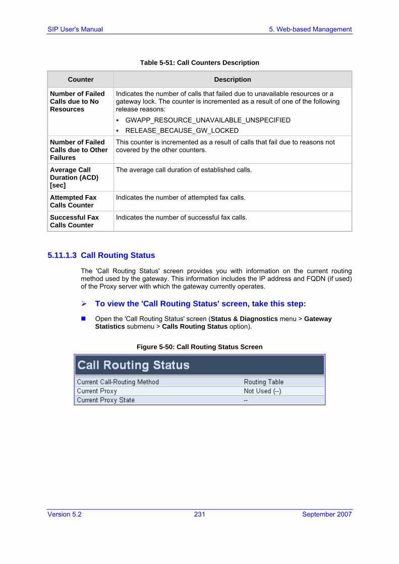
Version 5.2 231 September 2007
SIP User's Manual 5. Web-based Management
Table 5-51: Call Counters Description
Counter Description
Number of Failed Calls due to No Resources
Indicates the number of calls that failed due to unavailable resources or a gateway lock. The counter is incremented as a result of one of the following release reasons: GWAPP_RESOURCE_UNAVAILABLE_UNSPECIFIED RELEASE_BECAUSE_GW_LOCKED
Number of Failed Calls due to Other Failures
This counter is incremented as a result of calls that fail due to reasons not covered by the other counters.
Average Call Duration (ACD) [sec]
The average call duration of established calls.
Attempted Fax Calls Counter
Indicates the number of attempted fax calls.
Successful Fax Calls Counter
Indicates the number of successful fax calls.
5.11.1.3 Call Routing Status
The 'Call Routing Status' screen provides you with information on the current routing method used by the gateway. This information includes the IP address and FQDN (if used) of the Proxy server with which the gateway currently operates.
To view the 'Call Routing Status' screen, take this step:
Open the 'Call Routing Status' screen (Status & Diagnostics menu > Gateway Statistics submenu > Calls Routing Status option).
Figure 5-50: Call Routing Status Screen

SIP User's Manual 232 Document #: LTRT-68806
Mediant 2000 & TP-1610 & TP-260/UNI
Table 5-52: Call Routing Status Parameters
Parameter Description
Current Call-Routing Method Proxy = Proxy server is used to route calls. Routing Table preferred to Proxy = The Tel to IP Routing table
takes precedence over a Proxy for routing calls (PreferRouteTable = 1).
Routing Table = The Tel to IP Routing table is used to route calls.
Current Proxy Not Used = Proxy server isn't defined. IP address and FQDN (if exists) of the Proxy server the gateway
currently operates with.
Current Proxy State N/A = Proxy server isn't defined. OK = Communication with the Proxy server is in order. Fail = No response from any of the defined Proxies.
5.11.1.4 SAS Registered Users
The 'SAS Registered Users' screen provides you with a list of up to SAS Registered Users.
To view the 'SAS Registered Users' screen, take this step:
Open the 'SAS Registered Users' screen (Status & Diagnostics menu > Gateway Statistics submenu > SAS Registered Users option).
Figure 5-51: SAS Registered Users Screen
Table 5-53: SAS Registered Users Parameters
Column Name Description
Address of Record An address-of-record (AOR) is a SIP or SIPS URI that points to a domain with a location service that can map the URI to another URI (Contact) where the user might be available.
Contact SIP URI that can be used to contact that specific instance of the UA for subsequent requests.

Version 5.2 233 September 2007
SIP User's Manual 5. Web-based Management
5.11.2 Activating the Internal Syslog Viewer The 'Message Log' screen displays Syslog debug messages sent by the gateway. You can simply select the messages, and then copy and paste them into a text editor such as Notepad. This text file (txt) can then be sent to AudioCodes Technical Support for diagnosis and troubleshooting.
Note: It's not recommended to keep a Message Log session open (even if the window is minimized), for a prolonged period. This may cause the gateway to overload. For prolong debugging use an external Syslog server (refer to the SIP Series Reference Manual).
To activate the Message Log, take these 3 steps:
1. In the 'General Parameters' screen (Protocol Management menu > Advanced Parameters submenu > General Parameters option), set the parameter 'Debug Level' (or ini file parameter GwDebugLevel) to 5 (refer to 'General Parameters' on page 103). This parameter determines the Syslog logging level in the range 0 to 5, where 5 is the highest level.
2. Open the 'Message Log' screen (Status & Diagnostics menu > Message Log); the 'Message Log' screen is displayed and the log is activated.
Figure 5-52: Message Log Screen
3. To clear the screen of messages, click the submenu Message Log again; the screen is cleared and new messages begin appearing.
To de-activate the Message Log, take this step:
Close the screen by accessing any another screen.
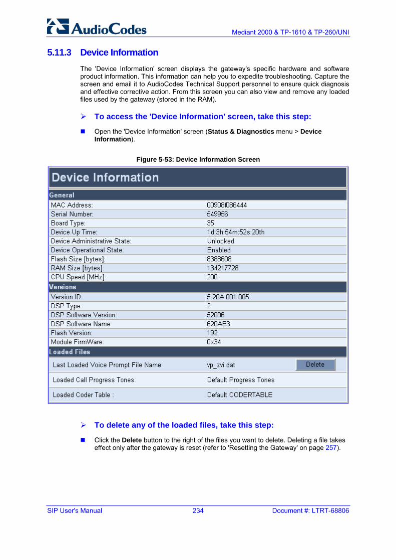
SIP User's Manual 234 Document #: LTRT-68806
Mediant 2000 & TP-1610 & TP-260/UNI
5.11.3 Device Information The 'Device Information' screen displays the gateway's specific hardware and software product information. This information can help you to expedite troubleshooting. Capture the screen and email it to AudioCodes Technical Support personnel to ensure quick diagnosis and effective corrective action. From this screen you can also view and remove any loaded files used by the gateway (stored in the RAM).
To access the 'Device Information' screen, take this step:
Open the 'Device Information' screen (Status & Diagnostics menu > Device Information).
Figure 5-53: Device Information Screen
To delete any of the loaded files, take this step:
Click the Delete button to the right of the files you want to delete. Deleting a file takes effect only after the gateway is reset (refer to 'Resetting the Gateway' on page 257).

Version 5.2 235 September 2007
SIP User's Manual 5. Web-based Management
5.11.4 Viewing the Ethernet Port Information The 'Ethernet Port Information' screen provides read-only information on the Ethernet connection used by the gateway. For detailed information on the Ethernet redundancy scheme, refer to 'Ethernet Interface Redundancy' on page 365. For detailed information on the Ethernet interface configuration, refer to 'Ethernet Interface Configuration' on page 365.
To view the Ethernet Port Information parameters, take the following step:
Open the ‘Ethernet Port Information’ screen (Status & Diagnostics menu > Ethernet Port Information submenu).
Figure 5-54: Ethernet Port Information Screen
Table 5-54: Ethernet Port Information Parameters
Parameter Description
Active Port Displays the active Ethernet port (1 or 2). (Not applicable to TP-260.)
Port 1 Duplex Mode Displays the Duplex mode Ethernet port 1 is using (Half Duplex or Full Duplex).
Port 1 Speed Displays the speed (in Mbps) that Ethernet port 1 is using (10 Mbps; 100 Mbps).
Port 2 Duplex Mode Displays the Duplex mode Ethernet port 2 is using (Half Duplex or Full Duplex). (Not applicable to TP-260.)
Port 2 Speed Displays the speed (in Mbps) that Ethernet port 2 is using (10 Mbps; 100 Mbps). (Not applicable to TP-260.)
5.11.5 Viewing Performance Statistics The Performance Statistic submenu provides read-only, gateway performance statistics. This menu includes the Basic Statistic, Control Protocol Statistics, Networking Statistics, DS1 Trunk Statistics, DSP Statistics screen.

SIP User's Manual 236 Document #: LTRT-68806
Mediant 2000 & TP-1610 & TP-260/UNI
To view performance statistics, take the following step:
Open the 'Basic Statistics’ screen (Status & Diagnostics menu > Performance Statistics submenu).
Figure 5-55: Basic Statistics Screen
To reset the performance statistics of a specific screen to zero, take the following step:
Click the Reset Statistics button.
5.11.6 Channel Status The 'Trunk & Channel Status' screen displays the status of the gateway's Trunks and channels pertaining to these trunks. In addition, it allows you to perform the following:
View specific trunk port settings (refer to 'Viewing Trunk Port Settings' on page 237)
Assign a name to a trunk port (refer to 'Assigning a Port Name' on page 238)
View detailed information of a selected channel (refer to 'Viewing Channel Information' on page 239)
To view trunk and channel status, take the following step:
Open the 'Trunk & Channel Status' screen (Status & Diagnostics menu > Channel Status submenu); the ‘Trunk & Channel Status' screen is displayed.
Figure 5-56: Trunk & Channel Status Screen

Version 5.2 237 September 2007
SIP User's Manual 5. Web-based Management
The number of trunks and channels that appear in the screen depends on the system configuration.
The 'Trunk and Channel Status' screen uses the following color coding to indicate the status of the trunks and channels:
Table 5-55: Color Coding for Trunk and Channel Status
SDH Trunk Channel
Icon Color Description Icon Color Description Icon Color Description
Grey Disabled Grey Disabled Grey In-active
Green No Alarms (Working)
Green Active - OK Green Active
Yellow No Alarms (Protection) Yellow RAI Alarm Pink SS7
Red LOS/LOF/MS-AIS/MS-RDA Alarm
Red LOS/LOF Alarm Dark Blue Non-voice
-- -- -- Blue AIS Alarm Blue ISDN Signaling
-- -- -- Orange D-channel Alarm Yellow CAS Blocked
5.11.6.1 Viewing Trunk Port Settings
From the 'Trunk & Channel Status' screen, you can access the 'Trunk Settings' screen. This provides an alternative method to directly accessing the 'Trunk Settings' screen from the Advanced Configuration menu (refer to 'Trunk Settings' on page 178).
To view the trunk port settings, take these 2 steps:
1. Click the icon of the trunk for which you want to view trunk settings; a shortcut menu appears, as shown in the figure below.
Figure 5-57: Shortcut Menu for Viewing Trunk Settings
2. From the shortcut menu, choose Port Settings; the 'Trunk Settings' screen appears, displaying the trunk settings of the selected trunk.
For a description of the 'Trunk Settings' screen, refer to 'Trunk Settings' on page 178.

SIP User's Manual 238 Document #: LTRT-68806
Mediant 2000 & TP-1610 & TP-260/UNI
5.11.6.2 Assigning a Port Name
The 'Trunk & Channel Status' screen allows you to assign an arbitrary name or brief description to each trunk / port. This description appears as a tooltip when you move your mouse over the specific trunk.
To add a port name, take these 3 steps:
1. In the 'Trunk & Channel Status' screen, click the trunk / port for which you want to assign a name; a shortcut menu appears, as shown in the figure below.
Figure 5-58: Shortcut Menu for Assigning a Port Name
2. From the shortcut menu, choose Update Port Info; a text box appears.
3. In the text box, type a name or brief description for the port, and then click Apply Port Info.

Version 5.2 239 September 2007
SIP User's Manual 5. Web-based Management
5.11.6.3 Viewing Channel Information
The 'Trunk & Channel Status' screen allows you to view detailed information regarding a selected trunk channel.
To view detailed channel information, take these 3 steps:
1. In the 'Trunk & Channel Status' screen, click the channel for which you want to view information; the 'Basic Information' screen appears, displaying basic information about the channel.
Figure 5-59: Basic Information Screen
2. To view additional channel information screens, click the buttons (SIP, RTP/RTCP, and Voice Settings) located above the screen.
3. To return to the 'Basic Information' screen, click the Basic button located above the screen.

SIP User's Manual 240 Document #: LTRT-68806
Mediant 2000 & TP-1610 & TP-260/UNI
5.12 Software Update The Software Update menu enables users to upgrade the gateway software by loading a new cmp file along with the ini file and a suite of auxiliary files, or to update the existing auxiliary files.
The Software Update menu includes the following submenus:
Software Upgrade Wizard (refer to 'Software Upgrade Wizard' on page 240)
Load Auxiliary Files (refer to 'Auxiliary Files' on page 247)
Software Upgrade Key (refer to 'Updating the Software Upgrade Key' on page 249)
Note: When upgrading the gateway software, you must load the new cmp file with all other related configuration files.
5.12.1 Software Upgrade Wizard The Software Upgrade Wizard guides you through the process of software upgrade: selecting files and loading them to the gateway. The wizard also enables you to upgrade software while maintaining the existing configuration. Using the wizard obligates you to load and burn a cmp file to the gateway. You can choose to also use the wizard to load the ini and auxiliary files (e.g., Call Progress Tones), but this option cannot be pursued without loading the cmp file. For the ini and each auxiliary file type, you can choose to reload an existing file, load a new file, or not load a file at all.
The Software Upgrade Wizard allows you to load the following files:
cmp (mandatory)
ini
Auxiliary files:
• CPT (Call Progress Tone)
• VP (Voice Prompts)
• PRT (Prerecorded Tones)
• CAS
• USRINF (User Info)
Warning: The Software Upgrade Wizard requires the gateway to be reset at the end of the process, which may disrupt its traffic. To avoid this, disable all traffic on the device before initiating the wizard by performing a graceful lock (refer to 'Locking and Unlocking the Gateway' on page 254).

Version 5.2 241 September 2007
SIP User's Manual 5. Web-based Management
Notes:
• When you activate the wizard, the rest of the Embedded Web Server interface is unavailable and the background Web screen is disabled. After the process is completed, access to the full Embedded Web Server is restored.
• The wizard allows you to load an ini or auxiliary file only after you have loaded a CMP file.
To use the Software Upgrade Wizard, take these 10 steps:
1. Stop all traffic on the gateway (refer to the note above).
2. Open the 'Software Upgrade Wizard' (Software Update menu > Software Upgrade Wizard); the 'Start Software Upgrade' screen appears.
Figure 5-60: Start Software Upgrade Wizard Screen
Note: At this stage, the Software Upgrade Wizard can be canceled (by clicking Cancel), without requiring a gateway reset. However, if you continue the wizard (by clicking the Start Software Upgrade button), the process must be followed through and completed with a gateway reset. If you click the Cancel button in any of the subsequent screens, the gateway is automatically reset with the configuration that was previously burned in flash memory.
3. Click the Start Software Upgrade button; the 'Load a cmp file' screen appears.

SIP User's Manual 242 Document #: LTRT-68806
Mediant 2000 & TP-1610 & TP-260/UNI
4. Click the Browse button, navigate to the cmp file, and then click Send File; the cmp file is loaded to the gateway and you're notified as to a successful loading, as shown below.

Version 5.2 243 September 2007
SIP User's Manual 5. Web-based Management
5. Note that the four action buttons (Cancel, Reset, Back, and Next) are now activated (following cmp file loading). You can now choose to either:
• Click Reset; the gateway resets, utilizing the new cmp you loaded and utilizing the current configuration files.
• Click Cancel; the gateway resets utilizing the cmp, ini and all other configuration files that were previously stored in flash memory. Note that these are NOT the files you loaded in the previous wizard steps.
• Click Back; the 'Load a cmp File' screen is displayed again.
• Click Next; the 'Load an ini File' screen opens; refer to the figure below. Loading a new ini file or any other auxiliary file listed in the wizard is optional.
Note that as you progress, the file type list on the left indicates which file type loading is in process by illuminating green (until 'Finish').
6. In the 'Load an ini File' screen, you can now choose to either:
• Click Browse and navigate to the ini file; the check box 'Use existing configuration', by default checked, becomes unchecked. Click Send File; the ini file is loaded to the gateway and you're notified as to a successful loading.
• Ignore the Browse button (its field remains undefined and the check box 'Use existing configuration' remains checked by default).
• Ignore the Browse button and uncheck the 'Use existing configuration' check box; no ini file is loaded, the gateway uses its factory-preconfigured values.
7. You can now choose to either:
• Click Cancel; the gateway resets utilizing the cmp, ini and all other configuration files that were previously stored in flash memory. Note that these are NOT the files you loaded in the previous Wizard steps.
• Click Reset; the gateway resets, utilizing the new cmp and ini file you loaded up to now as well as utilizing the other configuration files.
• Click Back; the 'Load a cmp file' screen is reverted to.
• Click Next; the next screen opens for loading a specific auxiliary file listed in the Wizard.
8. Follow the same procedure as for loading the ini file (Step 6) for loading the auxiliary files.

SIP User's Manual 244 Document #: LTRT-68806
Mediant 2000 & TP-1610 & TP-260/UNI
9. In the 'FINISH' screen (refer to the figure below), the Next button is disabled. Complete the upgrade process by clicking Reset or Cancel.
• Click Reset, the gateway 'burns' the newly loaded files to flash memory and then resets the gateway. After the gateway resets, the 'End Process' screen appears displaying the burned configuration files (refer to the figure below).
• Click Cancel, the gateway resets, utilizing the files previously stored in flash memory. (Note that these are NOT the files you loaded in the previous wizard steps).
Figure 5-61: End Process Wizard Screen
10. Click the End Process button; the 'Enter Network Password' screen appears requesting login username and password (described in 'Accessing the Embedded Web Server' on page 60). Once logged in, the Embedded Web Server reflects the upgraded gateway.

Version 5.2 245 September 2007
SIP User's Manual 5. Web-based Management
5.12.2 Automatic Update Mechanism The gateway can automatically update its cmp, ini, and configuration files. These files can be stored on any standard Web, FTP, or NFS server and can be loaded periodically to the gateway via HTTP, HTTPS, FTP, or NFS. This mechanism can be used even for gateways that are installed behind NAT and firewalls.
The Automatic Update mechanism is applied separately to each file. For a detailed list of available files and their corresponding parameters, refer to 'System Parameters' on page 280.
Note: The Automatic Update mechanism assumes the external Web server conforms to the HTTP standard. If the Web server ignores the If-Modified-Since header, or doesn’t provide the current date and time during the HTTP 200 OK response, the gateway may reset itself repeatedly. To overcome this problem, adjust the update frequency (AutoUpdateFrequency).
The following methods are used to activate the Automatic Update mechanism:
After the gateway starts up (refer to the Startup process described in 'Startup Process' on page 48).
At a configurable time of day (e.g., 18:00) using the ini file parameter AutoUpdatePredefinedTime. This option is disabled by default.
At fixed intervals (e.g., every 60 minutes) using the ini file parameter AutoUpdateFrequency. This option is disabled by default.
The following ini file example can be used to activate the Automatic Update mechanism.
# DNS is required for specifying domain names in URLs DnsPriServerIP = 10.1.1.11 # Load an extra configuration ini file using HTTP IniFileURL = 'http://webserver.corp.com/AudioCodes/inifile.ini' # Load Call Progress Tones file using HTTPS CptFileUrl = 'https://10.31.2.17/usa_tones.dat' # Load Voice Prompts file using FTPS with user ‘root’ and password ‘wheel’ VPFileUrl = 'ftps://root:[email protected]/vp.dat' # Update every day at 03:00 AM AutoUpdatePredefinedTime = '03:00' # Note: The cmp file isn’t updated since it's disabled by default (AutoUpdateCmpFile).
Note the following:
When HTTP or HTTPS are used, the gateway queries the Web server/s for the requested files. The ini file is loaded only if it was modified since the last automatic update. The cmp file is loaded only if its version is different from the version stored on the gateway's non-volatile memory. All other auxiliary files (e.g., CPT) are updated only once. To update a previously loaded auxiliary file, you must update the parameter containing its URL.
To load different configurations (ini files) for specific gateways, add the string ‘<MAC>’ to the URL. This mnemonic is replaced with the gateway's hardware MAC address, resulting in an ini file name request that contains the gateway's MAC address.

SIP User's Manual 246 Document #: LTRT-68806
Mediant 2000 & TP-1610 & TP-260/UNI
To automatically update the cmp file, use the parameter CmpFileURL to specify its name and location. As a precaution (to protect the gateway from an accidental update), by default, the Automatic Update mechanism doesn’t apply to the cmp file. Therefore, (to enable it) set the parameter AutoUpdateCmpFile to 1.
The following example illustrates how to utilize Automatic Updates for deploying gateway with minimum manual configuration.
To utilize Automatic Updates for deploying the gateway with minimum manual configuration, take these 5 steps:
1. Setup a Web server (e.g., http://www.corp.com) where all configuration files are located.
2. For each gateway, pre-configure the following parameter (DHCP / DNS are assumed): IniFileURL = 'http://www.corp.com/master_configuration.ini'
3. Create a file named master_configuration.ini with the following text:
# Common configuration for all devices # ------------------------------------ CptFileURL = 'http://www.corp.com/call_progress.dat' # Check for updates every 60 minutes AutoUpdateFrequency = 60 # Additional configuration per device # ----------------------------------- # Each device loads a file named after its MAC address, # (e.g., config_00908F033512.ini) IniFileURL = 'http://www.corp.com/config_<MAC>.ini' # Reset the device after configuration is updated. # The device resets after all of the files are processed.
You can modify the master_configuration.ini file (or any of the config_<MAC>.ini files) at any time. The gateway queries for the latest version every 60 minutes and applies the new settings immediately.
4. For additional security, use HTTPS or FTPS. The gateway supports HTTPS (RFC 2818) and FTPS using the AUTH TLS method <draft-murray-auth-ftp-ssl-16> for the Automatic Update mechanism.
5. To load configuration files from an NFS server, the NFS file system parameters should be defined in the configuration ini file. The following is an example of an ini file for loading files from NFS servers using NFS version 2.
# Define NFS servers for Automatic Update [ NFSServers ] FORMAT NFSServers_Index = NFSServers_HostOrIP, NFSServers_RootPath, NFSServers_NfsVersion; NFSServers 1 = 10.31.2.10, /usr/share, 2 ; NFSServers 2 = 192.168.100.7, /d/shared, 2 ; [ \NFSServers ] CptFileUrl = 'file://10.31.2.10/usr/share/public/usa_tones.dat' VpFileUrl = 'file://192.168.100.7/d/shared/audiocodes/voiceprompt.dat'

Version 5.2 247 September 2007
SIP User's Manual 5. Web-based Management
5.12.3 Auxiliary Files The 'Auxiliary Files' screen enables you to load various auxiliary files to the gateway, as described in the table below. (For detailed information on these files, refer to the SIP Series Reference Manual). For information on deleting these files from the gateway, refer to 'Device Information' on page 234.
Table 5-56: Auxiliary Files Descriptions
File Type Description
CAS Up to 8 different CAS files containing specific CAS protocol definitions for digital modules. These files are provided to support various types of CAS signaling.
Voice Prompts The voice announcement file contains a set of Voice Prompts (VP) to be played by the gateway during operation.
Dial Plan Dial plan file.
Call Progress Tones
This is a region-specific, telephone exchange-dependent file that contains the Call Progress Tones levels and frequencies that the VoIP gateway uses. The default CPT file is: U.S.A.
Prerecorded Tones The dat PRT file enhances the gateway's capabilities of playing a wide range of telephone exchange tones that cannot be defined in the Call Progress Tones file.
User Info The User Information file maps PBX extensions to IP numbers. This file can be used to represent PBX extensions as IP phones in the global 'IP world'.

SIP User's Manual 248 Document #: LTRT-68806
Mediant 2000 & TP-1610 & TP-260/UNI
5.12.3.1 Loading the Auxiliary Files via the Embedded Web Server
To load an auxiliary file to the gateway using the Embedded Web Server, take these 8 steps:
1. Open the 'Auxiliary Files' screen (Software Update menu > Load Auxiliary Files).
2. Click the Browse button corresponding to the type of file that you want to load.
3. Navigate to the folder that contains the file you want to load.
4. Select the file, and then click Open; the name and path of the file appear in the field next to the Browse button.
5. Click the Send File button corresponding to the field that contains the name of the file you want to load.
6. Repeat steps 2 through 5 for each file you want to load.
7. To save the loaded auxiliary files to flash memory, refer to 'Saving Configuration' on page 256.
8. To reset the gateway, refer to 'Resetting the Gateway' on page 257.

Version 5.2 249 September 2007
SIP User's Manual 5. Web-based Management
Notes:
• Saving an auxiliary file to flash memory may disrupt traffic on the gateway. To avoid this, disable all traffic on the device by performing a graceful lock (refer to 'Locking and Unlocking the Gateway' on page 254).
• File names preceded by an exclamation mark (!) are not changeable on-the-fly and require that the device be reset (e.g., Call Progress Tones file).
5.12.3.2 Loading the Auxiliary Files via the ini File
Before you load the auxiliary files (Call Progress Tones, Prerecorded Tones, User Information, Voice Prompts, Dial Plan, and CAS) to the gateway, in the ini file you need to define certain ini file parameters associated with these files. These ini file parameters specify the files that you want loaded and whether they must be stored in the non-volatile memory.
For a description of the ini file parameters associated with the auxiliary files, refer to 'Configuration Files Parameters' on page 337.
To load the auxiliary files via the ini file, take these 3 steps:
1. In the ini file, define the auxiliary files to be loaded to the gateway. You can also define in the ini file whether the loaded files must be stored in the non-volatile memory so that the TFTP process is not required every time the gateway boots up.
2. Save the auxiliary files you want to load and the ini file in the same directory on your PC.
3. Invoke a BootP/TFTP session; the ini and auxiliary files are loaded to the gateway.
5.12.4 Updating the Software Upgrade Key The gateways are supplied with a Software Upgrade Key for each of its TrunkPack Modules (TPM). You can later upgrade the gateway features, capabilities, and quantity of available resources by specifying what upgrades are required, and by purchasing a new key to match your requirements.
The Software Upgrade Key is provided in string format in a text file, which is loaded to the gateway. Stored in the gateway's non-volatile flash memory, the string defines the features and capabilities allowed by the specific key that is purchased. The gateway uses only these features and capabilities. A new key overwrites a previously installed key.
Notes:
• The Software Upgrade Key is an encrypted key. Each TPM utilizes a unique key.
• The Software Upgrade Key is provided only by AudioCodes.

SIP User's Manual 250 Document #: LTRT-68806
Mediant 2000 & TP-1610 & TP-260/UNI
5.12.4.1 Backing up the Current Software Upgrade Key
Backup your current Software Upgrade Key before loading a new key to the device. You can always re-load this backed-up key (refer to 'Loading the Software Upgrade Key' on page 250) to restore your device capabilities to what they originally were if the new key doesn’t comply with your requirements.
To backup the current Software Upgrade Key, take these 5 steps:
1. Access the devices Embedded Web Server (refer to 'Accessing the Embedded Web Server' on page 60).
2. Click the Software Update button.
3. Click the Software Upgrade Key tab; the Software Upgrade Key screen is displayed (shown in 'Using the Embedded Web Server' on page 250).
4. Copy the string of text from the 'Current Key' text box and paste it in a new text file.
5. Save the text file on your PC with a name of your choosing.
5.12.4.2 Loading the Software Upgrade Key
After receiving the Software Upgrade Key file, ensure that the first line displays "[LicenseKeys]" and that it contains one or more lines in the following format: S/N<Serial Number of TPM> = <long Software Upgrade Key>
For example: S/N370604 = jCx6r5tovCIKaBBbhPtT53Yj...
One S/N must match the S/N of your device. The device’s S/N can be viewed in the ‘Device Information’ screen (refer to 'Device Information' on page 234).
Warning: Don't modify the contents of the Software Upgrade Key file.
You can load a Software Upgrade Key using one of the following tools:
Embedded Web Server (refer to 'Using the Embedded Web Server' on page 250)
BootP/TFTP configuration utility (refer to the SIP Series Reference Manual)
AudioCodes’ EMS (refer to AudioCodes’ EMS User’s Manual or EMS Product Description)
5.12.4.2.1 Using the Embedded Web Server
The procedure below describes how to load a Software Upgrade Key to the gateway using the Embedded Web Server.
To load a Software Upgrade Key using the Embedded Web Server, take these 5 steps:
1. Access the devices Embedded Web Server (refer to 'Accessing the Embedded Web Server' on page 60).
2. Click the Software Update button.

Version 5.2 251 September 2007
SIP User's Manual 5. Web-based Management
3. Click the Software Upgrade Key tab; the 'Software Upgrade Key' screen is displayed (shown in the figure below).
• When loading a single key S/N line to a device:
a. Open the Software Upgrade Key file (using, for example, Microsoft® Notepad).
b. Select and copy the key string of the device’s S/N and paste it into the field 'New Key'. If the string is sent in the body of an email, copy and paste it from there.
c. Click the Add Key button.

SIP User's Manual 252 Document #: LTRT-68806
Mediant 2000 & TP-1610 & TP-260/UNI
• When loading a Software Upgrade Key text file containing multiple S/N lines to a device (refer to the figure below):
Figure 5-62: Software Upgrade Key with Multiple S/N Lines
a. Click the Browse button in the 'Send “Upgrade Key” file from your computer to the device' field, and navigate to the Software Upgrade Key text file.
b. Click the Send File button; the new key is loaded to the device and validated. If the key is valid, it's burned to memory. The new key is displayed in the 'Current Key' field.
4. Verify the presence of the appropriate features of the new key, by scrolling through the ‘Key features:’ group.
5. After verifying that the Software Upgrade Key was successfully loaded, reset the device; the new capabilities and resources are active.
5.12.4.2.2 Using BootP/TFTP
The procedure below describes how to load a Software Upgrade Key to the gateway using AudioCodes' BootP/TFTP Server utility.
To load a Software Upgrade Key file using BootP/TFTP, take these 6 steps:
1. Place the file in the same folder in which the gateway's cmp file is located. Note that to load the Software Upgrade Key via a TFTP server, the extension name of the key file must be ini.
2. Start the BootP/TFTP Server utility.
3. From the Services menu, choose Clients; the 'Client Configuration' screen is displayed (refer to the SIP Series Reference Manual).
4. From the 'INI File' drop-down list, select the Software Upgrade Key file. Note that the gateway's cmp file must be specified in the 'Boot File' field.
5. Configure the initial BootP/TFTP parameters as required (refer to the SIP Series Reference Manual), and then click OK.
6. Reset the gateway; the cmp and Software Upgrade Key files are loaded to the gateway.

Version 5.2 253 September 2007
SIP User's Manual 5. Web-based Management
5.12.4.3 Verifying that the Key was Successfully Loaded
You can verify if the Software Upgrade Key file has been successfully loaded to the gateway by using one of the following methods:
In the Embedded Web Server’s read-only ‘Key features:’ group (Software Update menu > Software Upgrade Key) (refer to 'Using the Embedded Web Server' on page 250), verify that the features and capabilities activated by the installed string match those that were ordered.
Access the Syslog server (refer to the SIP Series Reference Manual) and ensure that the following message appears in the Syslog server: 'S/N___ Key Was Updated. The Board Needs to be Reloaded with ini file\n'
5.12.4.4 Troubleshooting an Unsuccessful Loading of a Key
If the Syslog server indicates that a Software Upgrade Key file was unsuccessfully loaded (the SN_ line is blank), take the following preliminary actions to troubleshoot the issue:
Open the Software Upgrade Key file and check that the S/N line of the specific gateway whose key you want to update is listed. If it isn’t, contact AudioCodes.
Verify that you’ve loaded the correct file and that you haven’t loaded the gateway's ini file or the CPT ini file by mistake. Open the file and ensure that the first line displays "[LicenseKeys]".
Verify that you didn’t alter in any way the contents of the file.

SIP User's Manual 254 Document #: LTRT-68806
Mediant 2000 & TP-1610 & TP-260/UNI
5.13 Maintenance The Maintenance menu is used for the following operations:
Locking and unlocking the gateway (refer to 'Locking and Unlocking the Gateway' on page 254)
Saving the gateway's configuration (refer to 'Saving Configuration' on page 256)
Resetting the gateway (refer to 'Resetting the Gateway' on page 257)
5.13.1 Regional Settings The 'Regional Settings' screen allows you to define and view the gateway's internal date and time.
To configure the gateway's date and time, take these 3 steps:
1. Open the 'Regional Settings' screen (Advanced Configuration menu > Regional Settings).
Figure 5-63: Regional Settings Screen
2. Enter the time and date where the gateway is installed.
3. Click the Set Date & Time button; the date and time are automatically updated.
Notes:
• After performing a hardware reset, the date and time are returned to their defaults and should therefore be updated.
• For configuring the gateway to obtain the time from an SNTP server, refer to 'Simple Network Time Protocol Support' on page 372.
5.13.2 Locking and Unlocking the Gateway The Lock and Unlock options allow you to lock the gateway so that it doesn't accept any new incoming calls. This is beneficial when, for example, you are uploading new software files to the gateway and you don't want any traffic to interfere with the process.

Version 5.2 255 September 2007
SIP User's Manual 5. Web-based Management
To lock the gateway, take these 4 steps:
1. Open the 'Maintenance Actions' screen (Maintenance menu).
Figure 5-64: Maintenance Actions Screen
2. Under the 'LOCK / UNLOCK' group, from the 'Graceful Option' drop-down list, select one of the following options:
• 'Yes': The gateway is 'locked' only after the user-defined time in the 'Lock Timeout' field (refer to Step 3) expires or no more active traffic exists (the earliest thereof). In addition, no new traffic is accepted.
• 'No': The gateway is 'locked' regardless of traffic. Any existing traffic is terminated immediately.
3. In the 'Lock Timeout' field (relevant only if the 'Graceful Option' in the previous step is set to 'Yes'), enter the time (in seconds) after which the gateway locks. Note that if no traffic exists and the time has not yet expired, the gateway locks.
4. Click the LOCK button; If 'Graceful Option' is set to 'Yes', the lock is delayed and a screen displaying the number of remaining calls and time is displayed. Otherwise, the lock process begins immediately. The 'Current Admin State' field displays the current state: LOCKED or UNLOCKED.
To unlock the gateway, take these 2 steps:
1. Access the 'Maintenance Actions' screen as described above in the previous procedure.
2. Click the UNLOCK button. Unlock starts immediately and the gateway is ready for new incoming calls.

SIP User's Manual 256 Document #: LTRT-68806
Mediant 2000 & TP-1610 & TP-260/UNI
5.13.3 Saving Configuration The 'Maintenance Actions' screen enables you to save the current parameter configuration and the loaded auxiliary files to the gateway's non-volatile memory (i.e., flash) so they are available after a hardware reset (or power fail). Parameters that are only saved to the volatile memory (RAM) revert to their previous settings after a hardware reset.
Notes:
• Saving changes to the non-volatile memory may disrupt traffic on the gateway. To avoid this, disable all new traffic before saving by performing a graceful lock (refer to 'Locking and Unlocking the Gateway' on page 254).
• In the Embedded Web Server, parameters prefixed with an exclamation mark ('!') are saved to the non-volatile memory only after a device reset.
To save the changes to the non-volatile flash memory , take these 2 steps:
1. Open the 'Maintenance Actions' screen (Maintenance menu).
Figure 5-65: Maintenance Actions Screen
2. Click the BURN button; a confirmation message appears when the save is completed successfully.

Version 5.2 257 September 2007
SIP User's Manual 5. Web-based Management
5.13.4 Resetting the Gateway The 'Maintenance Actions' screen enables you to remotely reset the gateway. Before you reset the gateway, you can choose the following options:
Save the gateway's current configuration to the flash memory (non-volatile).
Perform a graceful shutdown. Reset starts only after a user-defined time expires or after no more active traffic exists (the earliest thereof).
To reset the gateway, take these 5 steps:
1. Open the 'Maintenance Actions' screen (Maintenance menu).
Figure 5-66: Maintenance Actions Screen
2. Under the 'RESET' group, from the 'Burn To FLASH' drop-down list, select one of the following options:
• 'Yes': The gateway's current configuration is burned (i.e., saved) to the flash memory prior to reset (default).
• 'No': Resets the device without burning (i.e., saving) the current configuration to flash (discards all unsaved modifications to the configuration).
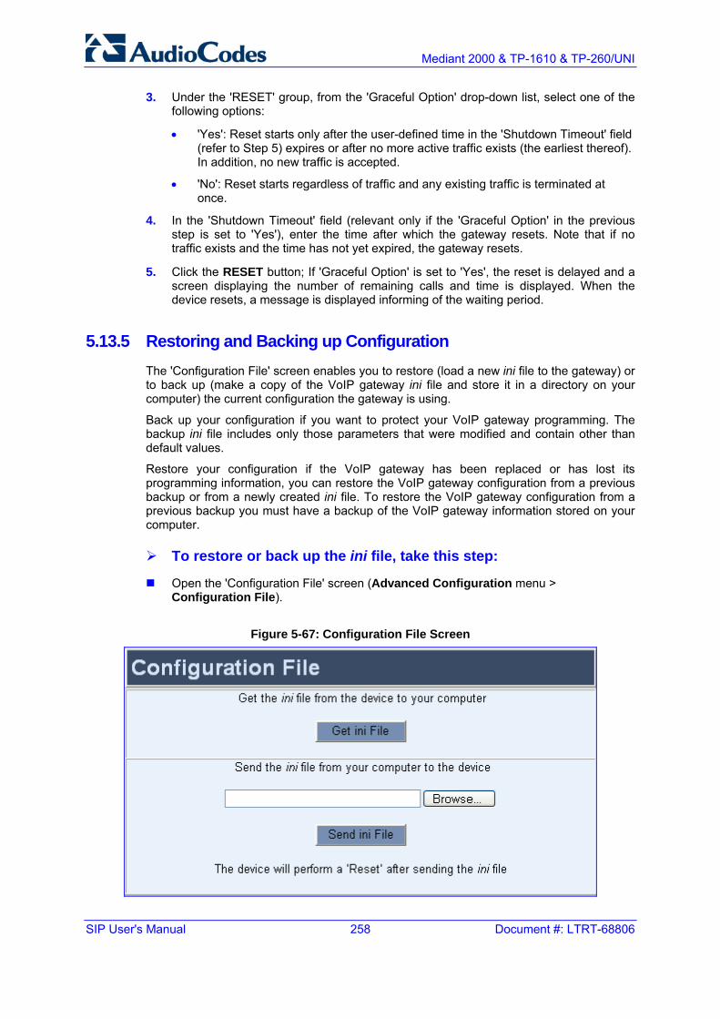
SIP User's Manual 258 Document #: LTRT-68806
Mediant 2000 & TP-1610 & TP-260/UNI
3. Under the 'RESET' group, from the 'Graceful Option' drop-down list, select one of the following options:
• 'Yes': Reset starts only after the user-defined time in the 'Shutdown Timeout' field (refer to Step 5) expires or after no more active traffic exists (the earliest thereof). In addition, no new traffic is accepted.
• 'No': Reset starts regardless of traffic and any existing traffic is terminated at once.
4. In the 'Shutdown Timeout' field (relevant only if the 'Graceful Option' in the previous step is set to 'Yes'), enter the time after which the gateway resets. Note that if no traffic exists and the time has not yet expired, the gateway resets.
5. Click the RESET button; If 'Graceful Option' is set to 'Yes', the reset is delayed and a screen displaying the number of remaining calls and time is displayed. When the device resets, a message is displayed informing of the waiting period.
5.13.5 Restoring and Backing up Configuration The 'Configuration File' screen enables you to restore (load a new ini file to the gateway) or to back up (make a copy of the VoIP gateway ini file and store it in a directory on your computer) the current configuration the gateway is using.
Back up your configuration if you want to protect your VoIP gateway programming. The backup ini file includes only those parameters that were modified and contain other than default values.
Restore your configuration if the VoIP gateway has been replaced or has lost its programming information, you can restore the VoIP gateway configuration from a previous backup or from a newly created ini file. To restore the VoIP gateway configuration from a previous backup you must have a backup of the VoIP gateway information stored on your computer.
To restore or back up the ini file, take this step:
Open the 'Configuration File' screen (Advanced Configuration menu > Configuration File).
Figure 5-67: Configuration File Screen

Version 5.2 259 September 2007
SIP User's Manual 5. Web-based Management
To back up the ini file on your PC, take these 4 steps:
1. Click the Get ini File button; the 'File Download' window opens.
2. Click the Save button; the 'Save As' window opens.
3. Navigate to the folder where you want to save the ini file on your PC.
4. Click the Save button; the VoIP gateway copies the ini file into the folder you selected.
To restore the ini file, take these 4 steps:
1. Click the Browse button.
2. Navigate to the folder that contains the ini file you want to load.
3. Click the file and click the Open button; the name and path of the file appear in the field beside the Browse button.
4. Click the Send ini File button, and then at the prompt, click OK; the gateway is automatically reset (from the cmp version stored on the flash memory).
5.13.6 Factory Default Settings
5.13.6.1 Defining Default Values
The gateway is shipped with factory default configuration values stored on its non-volatile flash memory. However, you can re-define your own default values instead of using the factory defaults. This is performed using another ini file (in addition to the standard ini file) that includes [ClientDefaults] as the header. Below this header, simply define new default values for the required ini file parameters. The parameters are defined in the same format as in the standard ini file, and loaded to the gateway using TFTP (not via the Embedded Web Server).
To define default values for gateway parameters, take these 2 steps:
1. Configure the ClientDefaults ini file with new default values for parameters, as needed.
2. Load the ClientDefaults ini file to the gateway using TFTP (refer to the SIP Series Reference Manual).
An example of the ClientsDefault ini file (changing default values for Syslog server parameters) is shown below:
[ClientDefaults] EnableSyslog = 1 SyslogServerIP = 10.13.2.20
To remove user-defined defaults and restore factory default values, take this step:
Load an empty (i.e., without any parameters) ClientDefaults ini file to the gateway, using TFTP.
SIP User's Manual 260 Document #: LTRT-68806
Mediant 2000 & TP-1610 & TP-260/UNI
5.13.6.2 Restoring Default Settings
You can use the gateway's hardware Reset button to restore all the gateway's configuration settings to default (e.g., IP address and login username and password). These default settings include factory as well as user-defined (refer to 'Defining Default Values' on page 259) defaults, where user-defined defaults override corresponding factory defaults.
To restore the gateway to default settings, take these 4 steps:
1. Disconnect the gateway from the power and network cables.
2. Reconnect the power cable; the gateway powers up. After approximately 45 seconds, the ACT LED flashes for about 4 seconds.
3. While the ACT LED is flashing, press the Reset button (located on the TP-1610's front panel); the gateway resets a second time and is restored with default parameters.
4. Reconnect the network cable.
5.14 Using the Home Page The Home icon, located above the main menu bar, opens the Home page. This page provides you with a graphical display of the gateway's front-panel, allowing you to view various gateway statuses.

Version 5.2 261 September 2007
SIP User's Manual 5. Web-based Management
5.14.1 Accessing the Home Page
To access the Home page, take this step:
Open the Home page by clicking the Home icon; the Home page is displayed.
Figure 5-68: Home Page
The table below describes the areas of the graphic display of the gateway chassis.
Table 5-57: Description of the Areas of the Home Page
Item# Description
1 ALARMS area for viewing the Active Alarms table. For a detailed description, refer to 'Viewing the Active Alarms Table' on page 263.
2 Blade status LEDs.
3 T1/E1 Trunk Status LEDs (for each of the 1 - 8 trunks). You can switch modules (refer to 'Switching Between Mediant 2000 Modules' on page 262), view port settings (refer to 'Viewing Trunk Settings' on page 264), and assign a name to a port (refer to 'Assigning a Name to a Port' on page 266).
4 Ethernet LEDs (green is active; grey is inactive). For a detailed description, refer to 'Viewing Ethernet Port Information' on page 262.
5 T1/E1 Trunk Status LEDs (for each of the 9 - 16 trunks).You can switch modules (refer to 'Switching Between Mediant 2000 Modules' on page 262), view port settings (refer to 'Viewing Trunk Settings' on page 264), and assign a name to a port (refer to 'Assigning a Name to a Port' on page 266).
6 Power LED.
7 Swap Ready LED.

SIP User's Manual 262 Document #: LTRT-68806
Mediant 2000 & TP-1610 & TP-260/UNI
The Home page also displays general information in the 'General Information' pane. This information includes parameters such as the gateway's IP address and firmware version.
5.14.2 Switching between Mediant 2000 Modules The Mediant 2000 consists of up to two modules, as discussed in previous sections. The graphical display of the Mediant 2000 displays only one of the modules to which you are connected. However, you can easily and quickly switch to the second module. When you do this, the Web browser connects to the IP address of the switched module.
To switch modules, take these 3 steps:
1. On the Home page, click on any one of the ports of the module to which you want to switch; a confirmation message box appears requesting you to confirm switching of modules.
Figure 5-69: Confirmation Message Box for Switching Modules
2. Click OK; the 'Enter Network Password' screen pertaining to the Embedded Web Server of the switched module appears.
3. Enter the login user name and password, and then click OK.
5.14.3 Viewing Ethernet Port Information The Home page allows you to view the 'Ethernet Port Information' screen, which provides read-only information on the Ethernet connection used by the gateway. Accessing this screen from the Home page provides an alternative to accessing it from the Status & Diagnostics menu (refer to 'Viewing Ethernet Port Information' on page 235).

Version 5.2 263 September 2007
SIP User's Manual 5. Web-based Management
To view Ethernet port information, take this step:
On the Home page, click the Ethernet Port Info LED on the TP-1610 (labeled as item #4 in the figure in 'Accessing the Home Page' on page 261); the 'Ethernet Port Information' screen opens.
Figure 5-70: Ethernet Port Information Screen
For detailed information on the Ethernet parameters, refer to 'Viewing Ethernet Port Information' on page 235.
5.14.4 Viewing the Active Alarms Table The Home page allows you to view a list of active alarms. These alarms are displayed in the 'Active Alarms' screen. For each alarm, the following is displayed:
Severity: severity level of the alarm:
• Critical: red
• Major: orange
• Minor: yellow
• No alarm: green
Source: module or unit from which the alarm was raised
Description: brief explanation of the alarm
Date: date and time that the alarm was generated

SIP User's Manual 264 Document #: LTRT-68806
Mediant 2000 & TP-1610 & TP-260/UNI
To view a list of alarms, take these 2 steps:
1. Open the Home page by clicking the Home icon; the Home page is displayed.
2. On the graphical display of the gateway front panel, click the orange area labeled 'ALARMS' or any area that displays the tooltip 'Click To Get Active Alarms Table'; the 'Active Alarms' screen appears.
Figure 5-71: Active Alarms Screen
5.14.5 Viewing Trunk Settings The Home page allows you to view the settings of a selected port in the 'Trunk Settings' screen. Accessing this screen from the Home page provides an alternative to accessing it from the Advanced Configuration menu ('Trunk Settings' on page 178).
To view port settings, take these 2 steps:
1. On the Home page, click a desired trunk port LED on the TP-1610 (labeled as items #3 and #5 in the figure in 'Accessing the Home Page' on page 261); a shortcut menu appears.
2. From the shortcut menu, choose Port Settings; the 'Trunk Settings' screen opens.

Version 5.2 265 September 2007
SIP User's Manual 5. Web-based Management
Figure 5-72: Trunk Settings Screen

SIP User's Manual 266 Document #: LTRT-68806
Mediant 2000 & TP-1610 & TP-260/UNI
5.14.6 Assigning a Name to a Port The Home page allows you to assign an arbitrary name or brief description to each gateway port. This description appears as a tooltip when you move your mouse over the specific port.
To add a port description, take these 4 steps:
1. Open the Home page by clicking the Home icon.
2. Click the required port icon; a shortcut menu appears.
3. From the shortcut menu, choose Update Port Info; a text box appears.
Figure 5-73: Shortcut Menu for Assigning a Port Name
4. Type a brief description for the port, and then click Apply Port Info.
5.15 Logging Off the Embedded Web Server The Log Off button enables you to log off the Embedded Web Server and to re-access it with a different account. For detailed information on the Web User Accounts, refer to 'User Accounts' on page 58.
To log off the Embedded Web Server, take these 2 steps:
1. Click the Log Off button on the main menu bar; the 'Log Off' prompt screen is displayed.
Figure 5-74: Log Off Confirmation Box
2. Click OK; the Web session is logged off.

Version 5.2 267 September 2007
SIP User's Manual 6. ini File Configuration
6 ini File Configuration As an alternative to configuring the gateway using the Embedded Web Server (refer to 'Web-based Management' on page 57), you can configure the gateway by loading the ini file containing user-defined parameters.
The ini file is loaded via the BootP/TFTP utility (refer to the SIP Series Reference Manual) or via any standard TFTP server. It can also be loaded using the Embedded Web Server (refer to 'Restoring and Backing up Configuration' on page 258).
The ini file configuration parameters are saved in the gateway's non-volatile memory after the file is loaded to the gateway. When a parameter is absent from the ini file, the default value is assigned to that parameter (according to the cmp file loaded to the gateway) and stored in the non-volatile memory (thereby overriding the value previously defined for that parameter). Therefore, to restore the gateway's default configuration parameters, use the ini file without any valid parameters or with a semicolon (;) preceding all lines in the file.
Some of the gateway's parameters are configurable only through the ini file (and not via the Embedded Web Server). These parameters usually determine a low-level functionality and are seldom changed for a specific application.
Note: For a list of the ini file parameters, refer to 'The ini File Parameter Reference' on page 272. The ini file parameters that are configurable through the Embedded Web Server are described in 'Web-based Management' on page 57.Those ini parameters that can't be configured using the Embedded Web Server are described in this section.
6.1 Secured ini File The ini file contains sensitive information that is required for the functioning of the gateway. It is loaded to, or retrieved from the device via TFTP or HTTP. These protocols are unsecured and vulnerable to potential hackers. Therefore, an encoded ini file significantly reduces these threats.
You can load an encoded ini file to the the gateway. When you load an encoded ini file, the retrieved ini file is also encoded. Use the 'TrunkPack Downloadable Conversion Utility' to encode or decode the ini file before you load it to, or retrieve it from the device. Note that the encoded ini file's loading procedure is identical to the regular ini file's loading procedure. For information on encoding / decoding an ini file, refer to the SIP Series Reference Manual.
6.2 Modifying an ini File
To modify an ini file, take these 4 steps:
1. Save the ini file from the gateway to your PC using the Embedded Web Server (refer to 'Restoring and Backing up Configuration' on page 258).
2. Open the ini file (using a text file editor such as Microsoft Notepad), and then modify the ini file parameters according to your requirements.

SIP User's Manual 268 Document #: LTRT-68806
Mediant 2000 & TP-1610 & TP-260/UNI
3. Save the new settings, and then close the file.
4. Load the modified ini file to the gateway (using either BootP/TFTP utility or the Embedded Web Server).
This method of modifying the ini file preserves the configuration that already exists in the device, including special default values that were preconfigured when the unit was manufactured.
Tip: Before loading the ini file to the gateway, verify that the file extension of the ini file saved on your PC is correct (i.e., xxx.ini). If the file extension name is not displayed, verify that the check box 'Hide extensions for known file types' (My Computer > Tools > Folder Options > View) is unchecked.
6.3 The ini File Content The ini file contains the following gateway information:
Networking parameters (refer to 'Networking Parameters' on page 273)
System parameters (refer to 'System Parameters' on page 280)
Web and Telnet parameters (refer to 'Web and Telnet Parameters' on page 287)
Security parameters (refer to 'Security' on page 290)
RADIUS parameters (refer to 'RADIUS Parameters' on page 291)
SNMP parameters (refer to 'SNMP Parameters' on page 293)
SIP Configuration parameters (refer to 'SIP Configuration Parameters' on page 295)
Media Server parameters (refer to 'Media Server Parameters' on page 306
Voice Mail parameters (refer to 'Voice Mail Parameters' on page 306)
PSTN parameters (refer to 'PSTN Parameters' on page 307)
ISDN and CAS Interworking-Related Parameters (refer to 'ISDN and CAS Interworking-Related Parameters' on page 311)
Number Manipulation and Routing parameters (refer to 'Number Manipulation and Routing Parameters' on page 318)
Channel Parameters (refer to 'Channel Parameters' on page 332)
Configuration Files parameters (refer to 'Configuration Files Parameters' on page 337)
6.4 The ini File Structure The ini file can contain any number of parameters. The ini file consists of individual parameters, which are conveniently grouped into subsections by their functionality, as well as table parameters, which include multiple ini file parameters. The ini file structure for the individual ini files and ini file parameter tables are described in 'Structure of Individual ini File Parameters' on page 269 and 'Configuring Parameter Tables Using the ini File' on page 269 respectively.

Version 5.2 269 September 2007
SIP User's Manual 6. ini File Configuration
6.4.1 The ini File Structure Rules The ini file must adhere to the following format rules:
The ini file name must not include hyphens or spaces; use underscore instead.
Lines beginning with a semi-colon (";") as the first character are ignored. These can be used for adding remarks in the ini file.
A carriage return (i.e., Enter) must be the final character of each line.
The number of spaces before and after the equals sign ("=") is not relevant.
If there is a syntax error in the parameter name, the value is ignored.
Syntax errors in the parameter value field can cause unexpected errors (parameters may be set to the incorrect values).
Sub-section names are optional.
String parameter values that denote file names (for example, for parameter CallProgressTonesFileName), must be placed between two inverted commas ('…').
The parameter name is not case-sensitive.
The parameter value is not case-sensitive, except for coder names.
The ini file must end with at least one carriage return.
6.4.2 Structure of Individual ini File Parameters The structure of the ini file containing individual ini file parameters is shown below:
[Subsection Name] Parameter_Name = Parameter_Value Parameter_Name = Parameter_Value ; REMARK
An example of an ini file containing individual ini file parameters is shown below:
[SYSTEM Params] SyslogServerIP = 10.13.2.69 EnableSyslog = 1 ; These are a few of the system-related parameters. [WEB Params] LogoWidth = '339' WebLogoText = '10.8.210.21' UseWeblogo = 1 ; These are a few of the Web-related parameters.
6.4.3 Structure of ini File Parameter Tables You can use the ini file to add / modify parameter tables. When using tables, read-only parameters are not loaded, as they cause an error when trying to reload the loaded file. Therefore, read-only parameters mustn’t be included in tables in the ini file. Consequently, tables are loaded with all parameters having at least one of the following permissions: Write, Create or Maintenance Write.

SIP User's Manual 270 Document #: LTRT-68806
Mediant 2000 & TP-1610 & TP-260/UNI
Parameter tables (in an uploaded ini file) are grouped according to the applications they configure (e.g., NFS and IPSec). When loading an ini file to the gateway, the recommended policy is to include only tables that belong to applications that are to be configured (Dynamic tables of other applications are empty, but static tables are not).
A table is defined as a secret table if it contains at least one secret data field or if it depends on another secret table. A secret data field is a field that mustn’t be revealed to the user. For example, in the IPSec application, IPSec tables are defined as secret tables as the IKE table contains a pre-shared key that must be concealed. Therefore, the SPD table that depends on the IKE table is defined as a secret table as well. Secret tables are never displayed in an uploaded ini file (e.g., when performing a 'Get ini File from Web' operation). Instead, there is a commented title that states that the secret table exists on the gateway, but is not to be revealed. Secret tables are always kept in the gateway's non-volatile memory and can be overwritten by new tables that are provided in a new ini file. If a secret table appears in an ini file, it replaces the current table regardless of its content. To delete a secret table from the gateway, provide an empty table of the same type (with no data lines) as part of a new ini file; the empty table replaces the previous table in the gateway.
The ini file includes a Format line that defines the columns of the table to be modified (this may vary from ini file to ini file for the same table). The Format line must only include columns that can be modified (parameters that are not specified as read-only). An exception is Index fields that are always mandatory.
Tables are composed of four elements:
Title of the table: The name of the table in square brackets (e.g., [MY_TABLE_NAME]).
Format line: Specifies the columns (parameters) of the table (by their string names) that are to be configured.
• The first word of the Format line must be 'FORMAT', followed by the Index field name, and then an equal sign '='. After the equal sign the names of the columns (parameters) are listed.
• Items must be separated by a comma ','.
• The Format line must end with a semicolon ';'.
Data line(s): Contain the actual values of the parameters. The values are interpreted according to the Format line. The first word of the Data line must be the table’s string name followed by the Index fields.
• Items must be separated by a comma ','.
• A Data line must end with a semicolon ';'.
End-of-Table-Mark: Indicates the end of the table. The same string used for the table’s title, preceded by a backslash '\' (e.g., [\MY_TABLE_NAME]).
The following displays an example of the structure of an ini file parameter table.
[Table_Title] ; This is the title of the table. FORMAT Item_Index = Item_Name1, Item_Name2, Item_Name3; ; This is the Format line. Item 0 = value1, value2, value3; Item 1 = value1, $$, value3; ; These are the Data lines. [\Table_Title] ; This is the end-of-the-table-mark.

Version 5.2 271 September 2007
SIP User's Manual 6. ini File Configuration
Refer to the following notes:
Indices (in both the Format and the Data lines) must appear in the same order determined by the specific table's documentation. The Index field must never be omitted.
The Format line can include a sub-set of the configurable fields in a table. In this case, all other fields are assigned with the pre-defined default values for each configured line.
The order of the fields in the Format line isn’t significant (as opposed to the Index-fields). The fields in the Data lines are interpreted according to the order specified in the Format line.
The sign '$$' in a Data line indicates that the user wants to assign the pre-defined default value to it.
The order of the Data lines is insignificant.
Data lines must match the Format line, i.e., it must contain exactly the same number of Indices and Data fields and must be in exactly the same order.
A line in a table is identified by its table-name and Index fields. Each such line may appear only once in the ini file.
Table dependencies: Certain tables may depend on other tables. For example, one table may include a field that specifies an entry in another table. This method is used to specify additional attributes of an entity, or to specify that a given entity is part of a larger entity. The tables must appear in the order of their dependency (i.e., if Table X is referred to by Table Y, Table X must appear in the ini file before Table Y). appear in the order of their dependency (i.e., if Table X is referred to by Table Y, Table X must appear in the ini file before Table Y).
The table below displays an example of an ini file parameter table:
[ PREFIX ] FORMAT PREFIX_Index = PREFIX_DestinationPrefix, PREFIX_DestAddress, PREFIX_SourcePrefix, PREFIX_ProfileId, PREFIX_MeteringCode, PREFIX_DestPort; PREFIX 0 = 10, 10.13.83.5, *, 0, 255, 0; PREFIX 1 = 20, 10.13.83.7, *, 0, 255, 0; PREFIX 2 = 30, 10.13.83.6, *, 0, 255, 0; PREFIX 3 = 20, 10.13.83.2, *, 0, 255, 0; [ \PREFIX ]

SIP User's Manual 272 Document #: LTRT-68806
Mediant 2000 & TP-1610 & TP-260/UNI
6.4.4 The ini File Example Below is an example of an ini file for the VoIP gateway.
PCMLawSelect = 1 ProtocolType = 1 TerminationSide = 0 FramingMethod = 0 LineCode = 2 TDMBusClockSource = 4 ClockMaster = 0 ;Channel Params DJBufMinDelay = 75 RTPRedundancyDepth = 1 IsProxyUsed = 1 ProxyIP = 192.168.122.179 [CoderName] FORMAT CoderName_Index = CoderName_Type, CoderName_PacketInterval, CoderName_rate, CoderName_PayloadType, CoderName_Sce; CoderName 1= g7231,90 [\CoderName] ;List of serial B-channel numbers [TrunkGroup] FORMAT TrunkGroup_Index = TrunkGroup_TrunkGroupNum, TrunkGroup_FirstTrunkId,TrunkGroup_LastTrunkId, TrunkGroup_FirstBChannel, TrunkGroup_LastBChannel, TrunkGroup_FirstPhoneNumber, TrunkGroup_ProfileId, TrunkGroup_Module; TrunkGroup 1 = 0,0,0,1,24,1000; TrunkGroup 2 = 0,1,1,1,24,2000; TrunkGroup 3 = 0,2,2,1,24,3000; TrunkGroup 4 = 0,3,3,1,24,4000; [\TrunkGroup] EnableSyslog = 1 SyslogServerIP = 10.2.2.1 CallProgressTonesFilename = 'CPUSA.dat' CASFileName = ‘E_M_WinkTable.dat’ SaveConfiguration = 1
6.5 The ini File Parameter Reference The subsections below list all the ini file parameters. References to their descriptions in the Embedded Web Server are provided, except for those ini file parameters that can only be configured using the ini file (and not the Embedded Web Server).

Version 5.2 273 September 2007
SIP User's Manual 6. ini File Configuration
6.5.1 Networking Parameters
Table 6-1: Networking Parameters
ini File Field Name Web Parameter Name Valid Range and Description
EthernetPhyConfiguration
Defines the Ethernet connection mode type. [0] = 10 Base-T half-duplex [1] = 10 Base-T full-duplex [2] = 100 Base-TX half-duplex [3] = 100 Base-TX full-duplex [4] = Auto-negotiate (default)
For detailed information on Ethernet interface configuration, refer to 'Ethernet Interface Configuration' on page 365.
DHCPEnable For a description of this parameter, refer to 'Configuring the IP Settings' on page 153.
EnableLANWatchDog For a description of this parameter, refer to 'General Parameters' on page 103.
DNSPriServerIP For a description of this parameter, refer to 'Configuring the IP Settings' on page 153.
DNSSecServerIP For a description of this parameter, refer to 'Configuring the IP Settings' on page 153.
DNS2IP The Internal DNS table is used to resolve host names to IP addresses. Two different IP addresses (in dotted format notation) can be assigned to a hostname. The format of this ini file parameter table is as follows: [Dns2Ip] FORMAT Dns2Ip_Index = Dns2Ip_DomainName, Dns2Ip_FirstIpAddress, Dns2Ip_SecondIpAddress; [\Dns2Ip] Where, DomainName = host name FirstIpAddress = first IP address SecondIpAddress =second IP address
For example: [Dns2Ip] Dns2Ip 0 = DnsName, 1.1.1.1, 2.2.2.2; [\Dns2Ip] Notes: If the internal DNS table is used, the gateway first attempts to resolve
a domain name using this table. If the domain name isn't found, the gateway performs a DNS resolution using an external DNS server.
This parameter can appear up to 10 times. For an explanation on ini file parameter tables, refer to 'Structure of ini
File Parameter Tables' on page 269.

SIP User's Manual 274 Document #: LTRT-68806
Mediant 2000 & TP-1610 & TP-260/UNI
Table 6-1: Networking Parameters
ini File Field Name Web Parameter Name Valid Range and Description
SRV2IP Defines the Internal SRV table used for resolving host names to DNS A-Records. Three different A-Records can be assigned to a hostname. Each A-Record contains the host name, priority, weight, and port. Format for this ini file parameter table: [SRV2IP] FORMAT SRV2IP_Index = SRV2IP_InternalDomain, SRV2IP_TransportType, SRV2IP_Dns1, SRV2IP_Priority1, SRV2IP_Weight1, SRV2IP_Port1, SRV2IP_Dns2, SRV2IP_Priority2, SRV2IP_Weight2, SRV2IP_Port2, SRV2IP_Dns3, SRV2IP_Priority3, SRV2IP_Weight3, SRV2IP_Port3; [\SRV2IP]
Where, InternalDomain = Internal domain name TransportType = Transport type Dns1, Dns2, Dns3 = DNS name 1, 2, and 3 Priority1, Priority2, Priority3 = Priority 1, 2, and 3 Weight1, Weight2, Weight3 = Weight 1, 2, and 3 Port1, Port2, Port3 = Port 1, 2, and 3
For example: [SRV2IP] SRV2IP 0 = SrvDomain,0,Dnsname1,1,1,500,Dnsname2,2,2,501,$$,0,0,0; [\SRV2IP] Notes: If the internal SRV table is used, the gateway first attempts to resolve
a domain name using this table. If the domain name isn't located, the gateway performs an SRV resolution using an external DNS server.
This parameter can appear up to 10 times. To configure the Internal SRV table using the Embedded Web Server,
refer to 'Internal SRV Table' on page 129. For an explanation on ini file parameter tables, refer to 'Structure of ini
File Parameter Tables' on page 269.
EnableSTUN For a description of this parameter, refer to 'Configuring the Application Settings' on page 157.
STUNServerPrimaryIP For a description of this parameter, refer to 'Configuring the Application Settings' on page 157.
STUNServerSecondaryIP For a description of this parameter, refer to 'Configuring the Application Settings' on page 157.
STUNServerDomainName
Defines the domain name for the Simple Traversal of User Datagram Protocol (STUN) server's address (used for retrieving all STUN servers with an SRV query). The STUN client can perform the required SRV query to resolve this domain name to an IP address and port, sort the server list, and use the servers according to the sorted list. Note: Use either the STUNServerPrimaryIP or the STUNServerDomainName parameter, with priority to the first one.

Version 5.2 275 September 2007
SIP User's Manual 6. ini File Configuration
Table 6-1: Networking Parameters
ini File Field Name Web Parameter Name Valid Range and Description
NATBindingDefaultTimeout
Defines the default NAT binding lifetime in seconds. STUN is used to refresh the binding information after this time expires. The valid range is 0 to 2,592,000. The default value is 30.
DisableNAT Enables / disables the Network Address Translation (NAT) mechanism. [0] = Enabled. [1] = Disabled (default).
Note: The compare operation that is performed on the IP address is enabled by default and is controlled by the parameter EnableIPAddrTranslation. The compare operation that is performed on the UDP port is disabled by default and is controlled by the parameter EnableUDPPortTranslation.
EnableIPAddrTranslation [0] = Disable IP address translation. [1] = Enable IP address translation for RTP, RTCP and T.38 packets
(default). [2] = Enable IP address translation for ThroughPacket™. [3] = Enable IP address translation for all protocols (RTP, RTCP, T38
and ThroughPacket™). When enabled, the gateway compares the source IP address of the first incoming packet, to the remote IP address stated in the opening of the channel. If the two IP addresses don't match, the NAT mechanism is activated. Consequently, the remote IP address of the outgoing stream is replaced by the source IP address of the first incoming packet. Note: The NAT mechanism must be enabled for this parameter to take effect (DisableNAT = 0).
EnableUDPPortTranslation
[0] = Disable UDP port translation (default). [1] = Enable UDP port translation.
When enabled, the gateway compares the source UDP port of the first incoming packet, to the remote UDP port stated in the opening of the channel. If the two UDP ports don't match, the NAT mechanism is activated. Consequently, the remote UDP port of the outgoing stream is replaced by the source UDP port of the first incoming packet. Note: The NAT mechanism and the IP address translation must be enabled for this parameter to take effect (DisableNAT = 0, EnableIpAddrTranslation = 1).
NoOpEnable Enables or disables the transmission of RTP or T.38 No-Op packets. [0] = Disable (default) [1] = Enable
This mechanism ensures that the NAT binding remains open during RTP or T.38 silence periods.
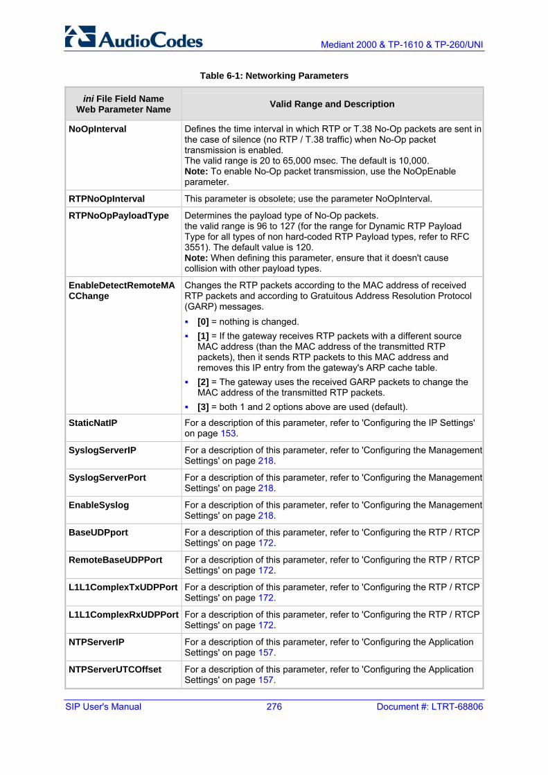
SIP User's Manual 276 Document #: LTRT-68806
Mediant 2000 & TP-1610 & TP-260/UNI
Table 6-1: Networking Parameters
ini File Field Name Web Parameter Name Valid Range and Description
NoOpInterval Defines the time interval in which RTP or T.38 No-Op packets are sent in the case of silence (no RTP / T.38 traffic) when No-Op packet transmission is enabled. The valid range is 20 to 65,000 msec. The default is 10,000. Note: To enable No-Op packet transmission, use the NoOpEnable parameter.
RTPNoOpInterval This parameter is obsolete; use the parameter NoOpInterval.
RTPNoOpPayloadType Determines the payload type of No-Op packets. the valid range is 96 to 127 (for the range for Dynamic RTP Payload Type for all types of non hard-coded RTP Payload types, refer to RFC 3551). The default value is 120. Note: When defining this parameter, ensure that it doesn't cause collision with other payload types.
EnableDetectRemoteMACChange
Changes the RTP packets according to the MAC address of received RTP packets and according to Gratuitous Address Resolution Protocol (GARP) messages. [0] = nothing is changed. [1] = If the gateway receives RTP packets with a different source
MAC address (than the MAC address of the transmitted RTP packets), then it sends RTP packets to this MAC address and removes this IP entry from the gateway's ARP cache table.
[2] = The gateway uses the received GARP packets to change the MAC address of the transmitted RTP packets.
[3] = both 1 and 2 options above are used (default).
StaticNatIP For a description of this parameter, refer to 'Configuring the IP Settings' on page 153.
SyslogServerIP For a description of this parameter, refer to 'Configuring the Management Settings' on page 218.
SyslogServerPort For a description of this parameter, refer to 'Configuring the Management Settings' on page 218.
EnableSyslog For a description of this parameter, refer to 'Configuring the Management Settings' on page 218.
BaseUDPport For a description of this parameter, refer to 'Configuring the RTP / RTCP Settings' on page 172.
RemoteBaseUDPPort For a description of this parameter, refer to 'Configuring the RTP / RTCP Settings' on page 172.
L1L1ComplexTxUDPPort For a description of this parameter, refer to 'Configuring the RTP / RTCP Settings' on page 172.
L1L1ComplexRxUDPPort For a description of this parameter, refer to 'Configuring the RTP / RTCP Settings' on page 172.
NTPServerIP For a description of this parameter, refer to 'Configuring the Application Settings' on page 157.
NTPServerUTCOffset For a description of this parameter, refer to 'Configuring the Application Settings' on page 157.

Version 5.2 277 September 2007
SIP User's Manual 6. ini File Configuration
Table 6-1: Networking Parameters
ini File Field Name Web Parameter Name Valid Range and Description
NTPUpdateInterval For a description of this parameter, refer to 'Configuring the Application Settings' on page 157.
IP Routing Table parameters: The IP routing ini file parameters are array parameters. Each parameter configures a specific column in the IP routing table. The first entry in each parameter refers to the first row in the IP routing table, the second entry to the second row and so forth. In the following example, two rows are configured when the gateway is in network 10.31.x.x: RoutingTableDestinationsColumn = 130.33.4.6, 83.4.87.6 RoutingTableDestinationMasksColumn = 255.255.255.255, 255.255.255.0 RoutingTableGatewaysColumn = 10.31.0.1, 10.31.0.112 RoutingTableInterfacesColumn = 0, 1 RoutingTableHopsCountColumn = 20, 20
RoutingTableDestinationsColumn
For a description of this parameter, refer to 'Configuring the IP Routing Table' on page 162.
RoutingTableDestinationMasksColumn
For a description of this parameter, refer to 'Configuring the IP Routing Table' on page 162.
RoutingTableGatewaysColumn
For a description of this parameter, refer to 'Configuring the IP Routing Table' on page 162.
RoutingTableHopsCountColumn
For a description of this parameter, refer to 'Configuring the IP Routing Table' on page 162.
RoutingTableInterfacesColumn
For a description of this parameter, refer to 'Configuring the IP Routing Table' on page 162.
VLAN Parameters
VLANMode For a description of this parameter, refer to 'Configuring the VLAN Settings' on page 164.
VLANNativeVLANID For a description of this parameter, refer to 'Configuring the VLAN Settings' on page 164.
VLANOamVLANID For a description of this parameter, refer to 'Configuring the VLAN Settings' on page 164.
VLANControlVLANID For a description of this parameter, refer to 'Configuring the VLAN Settings' on page 164.
VLANMediaVLANID For a description of this parameter, refer to 'Configuring the VLAN Settings' on page 164.
VLANNetworkServiceClassPriority
For a description of this parameter, refer to 'Configuring the VLAN Settings' on page 164.
VLANPremiumServiceClassMediaPriority
For a description of this parameter, refer to 'Configuring the VLAN Settings' on page 164.
VLANPremiumServiceClassControlPriority
For a description of this parameter, refer to 'Configuring the VLAN Settings' on page 164.
VlanGoldServiceClassPriority
For a description of this parameter, refer to 'Configuring the VLAN Settings' on page 164.

SIP User's Manual 278 Document #: LTRT-68806
Mediant 2000 & TP-1610 & TP-260/UNI
Table 6-1: Networking Parameters
ini File Field Name Web Parameter Name Valid Range and Description
VLANBronzeServiceClassPriority
For a description of this parameter, refer to 'Configuring the VLAN Settings' on page 164.
EnableDNSasOAM This parameter applies to both Multiple IPs and VLAN mechanisms. Multiple IPs: Determines the network type for DNS services. VLAN: Determines the traffic type for DNS services. [1] = OAM (default) [0] = Control.
EnableNTPasOAM This parameter applies to both Multiple IPs and VLAN mechanisms. Multiple IPs: Determines the network type for NTP services. VLAN: Determines the traffic type for NTP services. [1] = OAM (default) [0] = Control.
VLANSendNonTaggedOnNative
Specify whether to send non-tagged packets on the native VLAN. [0] = Sends priority tag packets (default). [1] = Sends regular packets (with no VLAN tag).
Multiple IPs Parameters
EnableMultipleIPs For a description of this parameter, refer to 'Configuring the IP Settings' on page 153.
LocalMediaIPAddress For a description of this parameter, refer to 'Configuring the IP Settings' on page 153.
LocalMediaSubnetMask For a description of this parameter, refer to 'Configuring the IP Settings' on page 153.
LocalMediaDefaultGW For a description of this parameter, refer to 'Configuring the IP Settings' on page 153.
LocalControlIPAddress For a description of this parameter, refer to 'Configuring the IP Settings' on page 153.
LocalControlSubnetMask For a description of this parameter, refer to 'Configuring the IP Settings' on page 153.
LocalControlDefaultGW For a description of this parameter, refer to 'Configuring the IP Settings' on page 153.
LocalOAMIPAddress For a description of this parameter, refer to 'Configuring the IP Settings' on page 153.
LocalOAMSubnetMask For a description of this parameter, refer to 'Configuring the IP Settings' on page 153.
LocalOAMDefaultGW For a description of this parameter, refer to 'Configuring the IP Settings' on page 153.
PPPoE Parameters
EnablePPPoE Enables the PPPoE (Point-to-Point Protocol over Ethernet) feature. [0] = Disable (default) [1] = Enable

Version 5.2 279 September 2007
SIP User's Manual 6. ini File Configuration
Table 6-1: Networking Parameters
ini File Field Name Web Parameter Name Valid Range and Description
PPPoEUserName User Name for PAP or Host Name for CHAP authentication. The valid range is a string of up to 47 characters. The default value is 0.
PPPoEPassword Password for PAP or Secret for CHAP authentication. The valid range is a string of up to 47 characters. The default value is 0.
PPPoEServerName Server Name for CHAP authentication. The valid range is a string of up to 47 characters. The default value is 0.
PPPoEStaticIPAddress
IP address to use in a static configuration setup. If set, used during PPP negotiation to request this specific IP address from the PPP server. If approved by the server, this IP address is used during the session. The valid IP address range is in dotted notation xxx.xxx.xxx.xxx. The default value is 0.0.0.0.
PPPoERecoverIPAddress
IP address to use when booting from the flash to non-PPPoE (Point-to-Point Protocol over Ethernet) environments. The valid IP address range is in dotted notation xxx.xxx.xxx.xxx. The default value is 10.4.10.4.
PPPoERecoverSubnetMask
Subnet Mask to use when booting from the flash to non-PPPoE (Point-to-Point Protocol over Ethernet) environments. The valid IP address range is in dotted notation xxx.xxx.xxx.xxx. The default value is 255.255.0.0.
PPPoERecoverDfGWAddress
Default Gateway address to use when booting from the flash to non-PPPoE (Point-to-Point Protocol over Ethernet) environments. The valid IP address range is in dotted notation xxx.xxx.xxx.xxx. The default value is 10.4.10.1.
PPPoELCPEchoEnable Enables or disables the Point-to-Point Protocol over Ethernet (PPPoE) disconnection auto-detection feature. [0] = Disable [1] = Enable (default)
By default, the PPPoE Client (i.e., embedded in the gateway) sends LCP Echo packets to the server to check that the PPPoE connection is open. Some Access Concentrators (PPPoE servers) don't reply to these LCP Echo requests, resulting in a disconnection. By disabling the LCP disconnection auto-detection feature, the PPPoE Client doesn't send LCP Echo packets to the server (and does not detect PPPoE disconnections).
Differential Services. For detailed information on IP QoS via Differentiated Services, refer to 'IP QoS via Differentiated Services (DiffServ)' on page 372.
NetworkServiceClassDiffServ
For a description of this parameter, refer to 'Configuring the IP Settings' on page 153.
PremiumServiceClassMediaDiffServ
For a description of this parameter, refer to 'Configuring the IP Settings' on page 153.
PremiumServiceClassControlDiffServ
For a description of this parameter, refer to 'Configuring the IP Settings' on page 153.
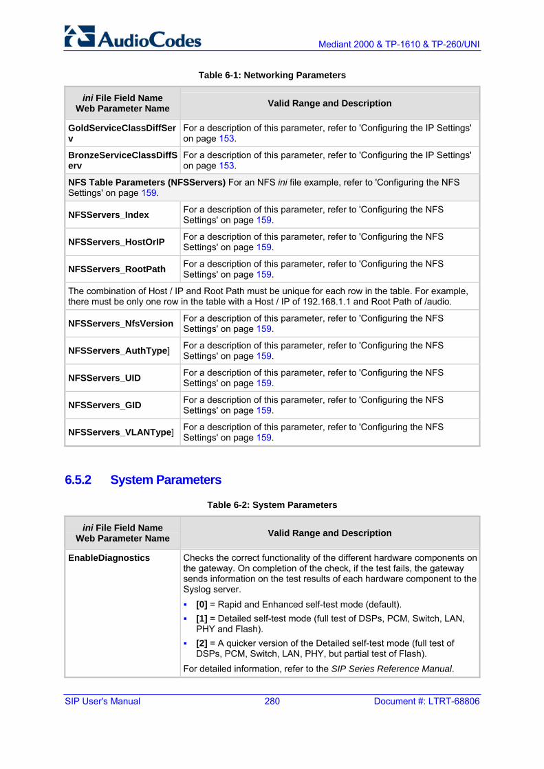
SIP User's Manual 280 Document #: LTRT-68806
Mediant 2000 & TP-1610 & TP-260/UNI
Table 6-1: Networking Parameters
ini File Field Name Web Parameter Name Valid Range and Description
GoldServiceClassDiffServ
For a description of this parameter, refer to 'Configuring the IP Settings' on page 153.
BronzeServiceClassDiffServ
For a description of this parameter, refer to 'Configuring the IP Settings' on page 153.
NFS Table Parameters (NFSServers) For an NFS ini file example, refer to 'Configuring the NFS Settings' on page 159.
NFSServers_Index For a description of this parameter, refer to 'Configuring the NFS Settings' on page 159.
NFSServers_HostOrIP For a description of this parameter, refer to 'Configuring the NFS Settings' on page 159.
NFSServers_RootPath For a description of this parameter, refer to 'Configuring the NFS Settings' on page 159.
The combination of Host / IP and Root Path must be unique for each row in the table. For example, there must be only one row in the table with a Host / IP of 192.168.1.1 and Root Path of /audio.
NFSServers_NfsVersion For a description of this parameter, refer to 'Configuring the NFS Settings' on page 159.
NFSServers_AuthType] For a description of this parameter, refer to 'Configuring the NFS Settings' on page 159.
NFSServers_UID For a description of this parameter, refer to 'Configuring the NFS Settings' on page 159.
NFSServers_GID For a description of this parameter, refer to 'Configuring the NFS Settings' on page 159.
NFSServers_VLANType] For a description of this parameter, refer to 'Configuring the NFS Settings' on page 159.
6.5.2 System Parameters
Table 6-2: System Parameters
ini File Field Name Web Parameter Name Valid Range and Description
EnableDiagnostics Checks the correct functionality of the different hardware components on the gateway. On completion of the check, if the test fails, the gateway sends information on the test results of each hardware component to the Syslog server. [0] = Rapid and Enhanced self-test mode (default). [1] = Detailed self-test mode (full test of DSPs, PCM, Switch, LAN,
PHY and Flash). [2] = A quicker version of the Detailed self-test mode (full test of
DSPs, PCM, Switch, LAN, PHY, but partial test of Flash). For detailed information, refer to the SIP Series Reference Manual.

Version 5.2 281 September 2007
SIP User's Manual 6. ini File Configuration
Table 6-2: System Parameters
ini File Field Name Web Parameter Name Valid Range and Description
GWAppDelayTime For a description of this parameter, refer to 'General Parameters' on page 103.
ActivityListToLog The Activity Log mechanism enables the gateway to send log messages (to a Syslog server) that report certain types of Web actions according to a pre-defined filter. The following filters are available: [PVC] (Parameters Value Change) - Changes made on-the-fly to
parameters. [AFL] (Auxiliary Files Loading) - Loading of auxiliary files (e.g., via
Certificate screen). [DR] (Device Reset) - Device reset via the Maintenance screen. [FB] (Flash Memory Burning) - Burning of files / parameters to flash
(e.g., Maintenance screen). [SWU] (Device Software Update) - cmp loading via the Software
Upgrade Wizard. [ARD] (Access to Restricted Domains) - Access to Restricted
Domains. The following screens are restricted: (1) ini parameters (AdminPage) (2) General Security Settings (3) Configuration File (4) IPSec/IKE tables (5) Software Upgrade Key (6) Internal Firewall (7) Web Access List. (8) Web User Accounts
[NAA] (Non Authorized Access) - Attempt to access the Embedded Web Server with a false / empty username or password.
[SPC] (Sensitive Parameters Value Change) - Changes made to sensitive parameters: (1) IP Address (2) Subnet Mask (3) Default Gateway IP Address (4) ActivityListToLog
For example: ActivityListToLog = 'pvc', 'afl', 'dr', 'fb', 'swu', 'ard', 'naa', 'spc'
ECHybridLoss Sets the four wire to two wire worst case Hybrid loss, the ratio between the signal level sent to the hybrid and the echo level returning from the hybrid. [0] = 6 dB (default) [1] = N/A [2] = 0 dB [3] = 3 dB
GwDebugLevel For a description of this parameter, refer to 'General Parameters' on page 103.

SIP User's Manual 282 Document #: LTRT-68806
Mediant 2000 & TP-1610 & TP-260/UNI
Table 6-2: System Parameters
ini File Field Name Web Parameter Name Valid Range and Description
CDRReportLevel For a description of this parameter, refer to 'General Parameters' on page 103.
CDRSyslogServerIP For a description of this parameter, refer to 'General Parameters' on page 103.
HeartBeatDestIP Destination IP address (in dotted format notation) to which the gateway sends proprietary UDP 'ping' packets. The default IP address is 0.0.0.0.
HeartBeatDestPort Destination UDP port to which the heartbeat packets are sent. The range is 0 to 64000. The default is 0.
HeartBeatIntervalmsec Delay (in msec) between consecutive heartbeat packets. [10] = 100000. [-1] = disabled (default).
EnableRAI [0] = Disable RAI (Resource Available Indication) service (default). [1] = Enable RAI service.
If RAI is enabled, an SNMP 'acBoardCallResourcesAlarm' Alarm Trap is sent if gateway's busy endpoints exceed a predefined (configurable) threshold.
RAIHighThreshold High Threshold (in percentage) that defines the gateway's busy endpoints. The range is 0 to 100. The default value is 90%. When the percentage of the gateway's busy endpoints exceeds the value configured in High Threshold, the gateway sends an SNMP 'acBoardCallResourcesAlarm' Alarm Trap with a 'major' Alarm Status. Note: The percentage of busy endpoints is calculated by dividing the number of busy endpoints by the total number of “enabled” endpoints (trunks are physically connected and synchronized with no alarms and endpoints are defined in the Trunk Group table).
RAILowThreshold Low Threshold (in percentage) that defines the gateway's busy endpoints. The range is 0 to 100. The default value is 90%. When the percentage of the gateway's busy endpoints falls below the value defined in Low Threshold, the gateway sends an SNMP 'acBoardCallResourcesAlarm' Alarm Trap with a 'cleared' Alarm Status.
RAILoopTime Time interval (in seconds) that the gateway checks for resource availability. The default is 10 seconds.
Disconnect Supervision Parameters
DisconnectOnBrokenConnection
For a description of this parameter, refer to 'General Parameters' on page 103.
BrokenConnectionEventTimeout
For a description of this parameter, refer to 'General Parameters' on page 103.
EnableSilenceDisconnect For a description of this parameter, refer to 'General Parameters' on page 103.

Version 5.2 283 September 2007
SIP User's Manual 6. ini File Configuration
Table 6-2: System Parameters
ini File Field Name Web Parameter Name Valid Range and Description
FarEndDisconnectSilencePeriod
For a description of this parameter, refer to 'General Parameters' on page 103.
FarEndDisconnectSilenceMethod
For a description of this parameter, refer to 'General Parameters' on page 103.
FarEndDisconnectSilenceThreshold
Threshold of the packet count (in percents), below which is considered silence by the gateway. The valid range is 1 to 100. The default is 8%. Note: Applicable only if silence is detected according to packet count (FarEndDisconnectSilenceMethod = 1).
Automatic Update Parameters
CmpFileURL Specifies the name of the cmp file and the location of the server (IP address or FQDN) from which the gateway loads a new cmp file and updates itself. The cmp file can be loaded using: HTTP, HTTPS, FTP, FTPS or NFS. For example: http://192.168.0.1/filename Notes: When this parameter is set in the ini file, the gateway always loads
the cmp file after it is reset. The cmp file is validated before it's burned to flash. The checksum of
the cmp file is also compared to the previously-burnt checksum to avoid unnecessary resets.
The maximum length of the URL address is 99 characters.
IniFileURL Specifies the name of the ini file and the location of the server (IP address or FQDN) from which the gateway loads the ini file. The ini file can be loaded using: HTTP, HTTPS, FTP, FTPS or NFS. For example: http://192.168.0.1/filename http://192.8.77.13/config<MAC> https://<username>:<password>@<IP address>/<file name>
Notes: When using HTTP or HTTPS, the date and time of the ini file are
validated. Only more recently-dated ini files are loaded. The optional string '<MAC>' is replaced with the gateway's MAC
address. Therefore, the gateway requests an ini file name that contains its MAC address. This option enables loading different configurations for specific gateways.
The maximum length of the URL address is 99 characters.
PrtFileURL Specifies the name of the Prerecorded Tones file and the location of the server (IP address or FQDN) from which it is loaded. For example: http://server_name/file, https://server_name/file. Note: The maximum length of the URL address is 99 characters.
CptFileURL Specifies the name of the CPT file and the location of the server (IP address or FQDN) from which it is loaded. For example: http://server_name/file, https://server_name/file. Note: The maximum length of the URL address is 99 characters.

SIP User's Manual 284 Document #: LTRT-68806
Mediant 2000 & TP-1610 & TP-260/UNI
Table 6-2: System Parameters
ini File Field Name Web Parameter Name Valid Range and Description
VpFileURL Specifies the name of the Voice Prompts file and the location of the server (IP address or FQDN) from which it is loaded.\ For example: http://server_name/file, https://server_name/file. Note: The maximum length of the URL address is 99 characters.
CasFileURL Specifies the name of the CAS file and the location of the server (IP address or FQDN) from which it is loaded. For example: http://server_name/file, https://server_name/file. Note: The maximum length of the URL address is 99 characters.
TLSRootFileUrl Specifies the name of the TLS trusted root certificate file and the location URL from where it's downloaded.
TLSCertFileUrl Specifies the name of the TLS certificate file and the location URL from where it's downloaded.
UserInfoFileURL Specifies the name of the User Information file and the location of the server (IP address or FQDN) from which it is loaded. For example: http://server_name/file, https://server_name/file. Note: The maximum length of the URL address is 99 characters.
AutoUpdateCmpFile Enables / disables the Automatic Update mechanism for the cmp file. [0] = The Automatic Update mechanism doesn't apply to the cmp file
(default). [1] = The Automatic Update mechanism includes the cmp file.
AutoUpdateFrequency Determines the number of minutes the gateway waits between automatic updates. The default value is 0 (the update at fixed intervals mechanism is disabled).
AutoUpdatePredefinedTime
Schedules an automatic update to a predefined time of the day. The range is 'HH:MM' (24-hour format). For example: 20:18 Note: The actual update time is randomized by five minutes to reduce the load on the Web servers.
ResetNow This parameter is now obsolete.
BootP and TFTP Parameters
The BootP parameters are special 'Hidden' parameters. Once defined and saved in the flash memory, they are used even if they don't appear in the ini file.
BootPRetries Note: This parameter only takes effect from the next reset of the gateway. This parameter is used to:

Version 5.2 285 September 2007
SIP User's Manual 6. ini File Configuration
Table 6-2: System Parameters
ini File Field Name Web Parameter Name Valid Range and Description
Set the number of BootP requests the gateway sends during start-up. The gateway stops sending BootP requests when either BootP reply is received or number of retries is reached. [1] = 1 BootP retry, 1 sec. [2] = 2 BootP retries, 3 sec. [3] = 3 BootP retries, 6 sec.
(default). [4] = 10 BootP retries, 30 sec. [5] = 20 BootP retries, 60 sec. [6] = 40 BootP retries, 120 sec. [7] = 100 BootP retries, 300 sec. [15] = BootP retries indefinitely.
Set the number of DHCP packets the gateway sends. After all packets were sent, if there's still no reply, the gateway loads from flash. [1] = 4 DHCP packets [2] = 5 DHCP packets [3] = 6 DHCP packets (default) [4] = 7 DHCP packets [5] = 8 DHCP packets [6] = 9 DHCP packets [7] = 10 DHCP packets [15] = 18 DHCP packets
BootPSelectiveEnable Enables the Selective BootP mechanism. [1] = Enabled. [0] = Disabled (default).
The Selective BootP mechanism (available from Boot version 1.92) enables the gateway's integral BootP client to filter unsolicited BootP/DHCP replies (accepts only BootP replies that contain the text 'AUDC' in the vendor specific information field). This option is useful in environments where enterprise BootP/DHCP servers provide undesired responses to the gateway's BootP requests. Note: When working with DHCP (DHCPEnable = 1) the selective BootP feature must be disabled.
BootPDelay The interval between the device's startup and the first BootP/DHCP request that is issued by the device. [1] = 1 second (default). [2] = 3 second. [3] = 6 second. [4] = 30 second. [5] = 60 second.
Note: This parameter only takes effect from the next reset of the device.

SIP User's Manual 286 Document #: LTRT-68806
Mediant 2000 & TP-1610 & TP-260/UNI
Table 6-2: System Parameters
ini File Field Name Web Parameter Name Valid Range and Description
ExtBootPReqEnable [0] = Disable (default). [1] = Enable extended information to be sent in BootP request.
If enabled, the device uses the vendor specific information field in the BootP request to provide device-related initial startup information such as blade type, current IP address, software version, etc. For a full list of the vendor specific Information fields, refer to the SIP Series Reference Manual. The BootP/TFTP configuration utility displays this information in the 'Client Info' column (refer to the SIP Series Reference Manual). Note: This option is not available on DHCP servers.
Serial Parameters
DisableRS232 [0] = RS-232 serial port is enabled (default). [1] = RS-232 serial port is disabled.
The RS-232 serial port can be used to change the networking parameters (refer to 'Assigning an IP Address Using the CLI' on page 51) and view error / notification messages. For information on establishing a serial communications link with the gateway, refer to 'Accessing the CLI' on page 52.
SerialBaudRate Determines the value of the RS-232 baud rate. The valid range is any value. It is recommended to use the following standard values: 1200, 2400, 9600 (default), 14400, 19200, 38400, 57600, 115200.
SerialData Determines the value of the RS-232 data bit. [7] = 7-bit. [8] = 8-bit (default).
SerialParity Determines the value of the RS-232 polarity. [0] = None (default). [1] = Odd. [2] = Even.
SerialStop Determines the value of the RS-232 stop bit. [1] = 1-bit (default). [2] = 2-bit.
SerialFlowControl Determines the value of the RS-232 flow control. [0] = None (default). [1] = Hardware.

Version 5.2 287 September 2007
SIP User's Manual 6. ini File Configuration
6.5.3 Web and Telnet Parameters
Table 6-3: Web and Telnet Parameters
ini File Field Name Web Parameter Name Valid Range and Description
WebAccessList_x Defines up to ten IP addresses that are permitted to access the gateway's Embedded Web Server and Telnet interfaces. Access from an undefined IP address is denied. This security feature is inactive (the gateway can be accessed from any IP address) when the table is empty.For example: WebAccessList_0 = 10.13.2.66 WebAccessList_1 = 10.13.77.7 The default value is 0.0.0.0 (the gateway can be accessed from any IP address). For defining the Web and Telnet Access list using the Embedded Web Server, refer to 'Configuring the Web and Telnet Access List' on page 199.
WebRADIUSLogin For a description of this parameter, refer to 'Configuring the General Security Settings' on page 206.
DisableWebTask [0] = Enable Web management (default). [1] = Disable Web management.
ResetWebPassword Resets the username and password of the primary and secondary accounts to their defaults. [0] = Password and username retain their values (default). [1] = Password and username are reset (for the default username
and password, refer to 'User Accounts' on page 58). Note: The username and password cannot be reset from the Embedded Web Server (i.e., via AdminPage or by loading an ini file).

SIP User's Manual 288 Document #: LTRT-68806
Mediant 2000 & TP-1610 & TP-260/UNI
Table 6-3: Web and Telnet Parameters
ini File Field Name Web Parameter Name Valid Range and Description
WelcomeMessage Configures the Welcome message that appears after a Embedded Web Server login. The format of this ini file parameter table is: [WelcomeMessage ] FORMAT WelcomeMessage_Index = WelcomeMessage_Text WelcomeMessage 1 = "..." ; WelcomeMessage 2 = "..." ; WelcomeMessage 3 = "..." ; [\WelcomeMessage] For Example: [WelcomeMessage ] FORMAT WelcomeMessage_Index = WelcomeMessage_Text WelcomeMessage 1 = "**********************************" ; WelcomeMessage 2 = "********* This is a Welcome message ***" ; WelcomeMessage 3 = "**********************************" ; [\WelcomeMessage]
Notes: Each index represents a line of text in the Welcome message box. Up
to 20 indexes can be defined. If this parameter is not configured, no Welcome message box is
displayed.
DisableWebConfig [0] = Enable changing parameters from Embedded Web Server (default).
[1] = Operate Embedded Web Server in 'read only' mode.
HTTPport HTTP port used for Web management (default is 80).
Telnet Parameters
TelnetServerEnable For a description of this parameter, refer to 'Configuring the Application Settings' on page 157.
TelnetServerPort For a description of this parameter, refer to 'Configuring the Application Settings' on page 157.
TelnetServerIdleDisconnect
For a description of this parameter, refer to 'Configuring the Application Settings' on page 157.
SSHServerEnable For a description of this parameter, refer to 'Configuring the Application Settings' on page 157.
SSHServerPort For a description of this parameter, refer to 'Configuring the Application Settings' on page 157.

Version 5.2 289 September 2007
SIP User's Manual 6. ini File Configuration
Table 6-3: Web and Telnet Parameters
ini File Field Name Web Parameter Name Valid Range and Description
Customizing the Web Appearance Parameters For detailed information on customizing the Embedded Web Server interface, refer to 'Customizing the Web Interface' on page 65.
UseProductName Determines whether the UserProductName text string is displayed instead of the default product name. [0] = Disabled (default). [1] = Enables the display of the user-defined UserProductName text
string (in the Embedded Web Server interface and in the extracted inifile).
If enabled, the UserProductName text string is displayed instead of the default product name.
UserProductName Text string that replaces the default product name that appears in the Embedded Web Server (upper right-hand corner) and the extracted ini file. The default is 'Mediant 2000, TP-1610, or TP-260'. The string can be up to 29 characters.
UseWebLogo [0] = Logo image is used (default). [1] = Text string is used instead of a logo image.
If enabled, AudioCodes' default logo (or any other logo defined by the LogoFileName parameter) is replaced with a text string defined by the WebLogoText parameter.
WebLogoText Text string that replaces the logo image. The string can be up to 15 characters.
LogoWidth Width (in pixels) of the logo image. Note: The optimal setting depends on the resolution settings. The default value is 441, which is the width of AudioCodes' displayed logo.
LogoFileName Name of the image file (of type GIF, JPEG, or JPG) containing the user's logo. File name can be up to 47 characters. The logo file name can be used to replace AudioCodes' default Web logo with a user defined logo.
BkgImageFileName Name of the file containing the user's background image (of file type GIF, JPEG, or JPG). File name can be up to 47 characters. The background file can be used to replace AudioCodes' default background image with a user defined background.

SIP User's Manual 290 Document #: LTRT-68806
Mediant 2000 & TP-1610 & TP-260/UNI
6.5.4 Security Parameters
Table 6-4: Security Parameters
ini File Field Name Web Parameter Name Valid Range and Description
EnableIPSec For a description of this parameter, refer to 'Configuring the General Security Settings' on page 206.
EnableMediaSecurity For a description of this parameter, refer to 'Configuring the General Security Settings' on page 206.
MediaSecurityBehaviour For a description of this parameter, refer to 'Configuring the General Security Settings' on page 206.
EnableSIPS For a description of this parameter, refer to 'General Parameters' on page 103.
TLSVersion For a description of this parameter, refer to 'Configuring the General Security Settings' on page 206.
TLSLocalSIPPort For a description of this parameter, refer to 'General Parameters' on page 103.
SIPSRequireClientCertificate
[0] = The gateway doesn't require client certificate (default). [1] = The gateway (when acting as a server for the TLS connection)
requires reception of client certificate to establish the TLS connection.Note: The SIPS certificate files can be changed using the parameters HTTPSCertFileName and HTTPSRootFileName.
Secure Hypertext Transport Protocol (HTTPS) Parameters
HTTPSOnly For a description of this parameter, refer to 'Configuring the General Security Settings' on page 206.
HTTPSPort Determine the local Secured HTTPS port of the device. The valid range is 1 to 65535 (other restrictions may apply within this range). The default port is 443.
HTTPSCipherString Defines the Cipher string for HTTPS (in OpenSSL cipher list format). Refer to URL http://www.openssl.org/docs/apps/ciphers.html. The range is EXP, RC4. Default is 0.
WebAuthMode For a description of this parameter, refer to 'Configuring the General Security Settings' on page 206.
HTTPSRequireClientCertificate
Requires client certificates for HTTPS connection. The client certificate must be preloaded to the gateway, and its matching private key must be installed on the managing PC. Time and date must be correctly set on the gateway, for the client certificate to be verified. [0] = Client certificates are not required (default). [1] = Client certificates are required.
HTTPSRootFileName Defines the name of the HTTPS trusted root certificate file to be loaded via TFTP. The file must be in base64-encoded PEM (Privacy Enhanced Mail) format. The valid range is a 47-character string. Note: This parameter is only relevant when the gateway is loaded via BootP/TFTP. For information on loading this file via the Embedded Web Server, refer to the SIP Series Reference Manual.

Version 5.2 291 September 2007
SIP User's Manual 6. ini File Configuration
Table 6-4: Security Parameters
ini File Field Name Web Parameter Name Valid Range and Description
HTTPSPkeyFileName Defines the name of a private key file (in unencrypted PEM format) to be loaded from the TFTP server.
HTTPSCertFileName Defines the name of the HTTPS server certificate file to be loaded via TFTP. The file must be in base64-encoded PEM format. The valid range is a 47-character string. Note: This parameter is only relevant when the gateway is loaded via BootP/TFTP. For information on loading this file via the Embedded Web Server, refer to the SIP Series Reference Manual.
Internal Firewall Parameters
AccessList_Source_IP For a description of this parameter, refer to 'Configuring the Firewall Settings' on page 200.
AccessList_Net_Mask For a description of this parameter, refer to 'Configuring the Firewall Settings' on page 200.
AccessList_Start_Port AccessList_End_Port
For a description of this parameter, refer to 'Configuring the Firewall Settings' on page 200.
AccessList_Protocol For a description of this parameter, refer to 'Configuring the Firewall Settings' on page 200.
AccessList_Packet_Size For a description of this parameter, refer to 'Configuring the Firewall Settings' on page 200.
AccessList_Byte_Rate For a description of this parameter, refer to 'Configuring the Firewall Settings' on page 200.
AccessList_Byte_Burst For a description of this parameter, refer to 'Configuring the Firewall Settings' on page 200.
AccessList_Allow_Type For a description of this parameter, refer to 'Configuring the Firewall Settings' on page 200.
AccessList_MatchCount For a description of this parameter, refer to 'Configuring the Firewall Settings' on page 200.
6.5.5 RADIUS Parameters For detailed information on the supported RADIUS attributes, refer to 'Supported RADIUS Attributes' on page 354.
Table 6-5: RADIUS Parameter
ini File Field Name Web Parameter Name Valid Range and Description
EnableRADIUS For a description of this parameter, refer to 'Configuring the General Security Settings' on page 206.
AAAIndications For a description of this parameter, refer to 'Configuring RADIUS Accounting Parameters' on page 147.

SIP User's Manual 292 Document #: LTRT-68806
Mediant 2000 & TP-1610 & TP-260/UNI
Table 6-5: RADIUS Parameter
ini File Field Name Web Parameter Name Valid Range and Description
MaxRADIUSSessions Number of concurrent calls that can communicate with the RADIUS server (optional). The valid range is 0 to 240. The default value is 240.
SharedSecret For a description of this parameter, refer to 'Configuring the General Security Settings' on page 206.
RADIUSRetransmission Number of retransmission retries. The valid range is 1 to 10. The default value is 3.
RadiusTO Determines the time interval (measured in seconds) the gateway waits for a response before a RADIUS retransmission is issued. The valid range is 1 to 30. The default value is 10.
RADIUSAuthServerIP For a description of this parameter, refer to 'Configuring the General Security Settings' on page 206.
RADIUSAuthPort For a description of this parameter, refer to 'Configuring the General Security Settings' on page 206.
RADIUSAccServerIP For a description of this parameter, refer to 'Configuring RADIUS Accounting Parameters' on page 147.
RADIUSAccPort For a description of this parameter, refer to 'Configuring RADIUS Accounting Parameters' on page 147.
RadiusAccountingType For a description of this parameter, refer to 'Configuring RADIUS Accounting Parameters' on page 147.
DefaultAccessLevel For a description of this parameter, refer to 'Configuring the General Security Settings' on page 206.
RadiusLocalCacheMode For a description of this parameter, refer to 'Configuring the General Security Settings' on page 206.
RadiusLocalCacheTimeout
For a description of this parameter, refer to 'Configuring the General Security Settings' on page 206.
RadiusVSAVendorID For a description of this parameter, refer to 'Configuring the General Security Settings' on page 206.
RadiusVSAAccessAttribute
For a description of this parameter, refer to 'Configuring the General Security Settings' on page 206.

Version 5.2 293 September 2007
SIP User's Manual 6. ini File Configuration
6.5.6 SNMP Parameters
Table 6-6: SNMP Parameters
ini File Field Name Web Parameter Name Valid Range and Description
DisableSNMP For a description of this parameter, refer to 'Configuring the Management Settings' on page 218.
SNMPPort The device's local UDP port used for SNMP Get/Set commands. The range is 100 to 3999. The default port is 161.
SNMPTrustedMGR_x Up to five IP addresses of remote trusted SNMP managers from which the SNMP agent accepts and processes get and set requests. Notes: If no values are assigned to these parameters any manager can
access the device. Trusted managers can work with all community strings.
KeepAliveTrapPort The port to which the keep-alive traps are sent. The valid range is 0 - 65534. The default is port 162.
SendKeepAliveTrap When enabled, this parameter invokes the keep-alive trap and sends it every 9/10 of the time defined in the parameter defining NAT Binding Default Timeout. [0] = Disable [1] = Enable
SNMPSysOid Defines the base product system OID. Default is eSNMP_AC_PRODUCT_BASE_OID_D.
SNMPTrapEnterpriseOid Defines a Trap Enterprise OID. Default is eSNMP_AC_ENTERPRISE_OID. The inner shift of the trap in the AcTrap subtree is added to the end of the OID in this parameter.
acUserInputAlarmDescription Defines the description of the input alarm.
acUserInputAlarmSeverity Defines the severity of the input alarm.
AlarmHistoryTableMaxSize Determines the maximum number of rows in the Alarm History table. The parameter can be controlled by the Config Global Entry Limit MIB (located in the Notification Log MIB). The valid range is 50 to 1000. The default value is 500.
SNMP Trap Parameters
SNMPManagerTableIP_x For a description of this parameter, refer to 'Configuring the SNMP Managers Table' on page 221.
SNMPManagerTrapPort_x For a description of this parameter, refer to 'Configuring the SNMP Managers Table' on page 221.

SIP User's Manual 294 Document #: LTRT-68806
Mediant 2000 & TP-1610 & TP-260/UNI
Table 6-6: SNMP Parameters
ini File Field Name Web Parameter Name Valid Range and Description
SNMPManagerTrapUser_x This parameter can be set to the name of any configured SNMPV3 user to associate with this trap destination. This determines the trap format, authentication level, and encryption level. By default, the trap is associated with the SNMP trap community string.
SNMPManagerIsUsed_x For a description of this parameter, refer to 'Configuring the SNMP Managers Table' on page 221.
SNMPManagerTrapSendingEnable_x
For a description of this parameter, refer to 'Configuring the SNMP Managers Table' on page 221.
SNMPTrapManagerHostName For a description of this parameter, refer to 'Configuring the Management Settings' on page 218.
SNMP Community String Parameters
SNMPReadOnlyCommunityString_x
For a description of this parameter, refer to 'Configuring the SNMP Community Strings' on page 222.
SNMPReadWriteCommunityString_x
For a description of this parameter, refer to 'Configuring the SNMP Community Strings' on page 222.
SNMPTrapCommunityString For a description of this parameter, refer to 'Configuring the SNMP Community Strings' on page 222.
SNMP v3 Users Parameters
SNMPUsers_Index For a description of this parameter, refer to 'Configuring SNMP V3 Users' on page 224.
SNMPUsers_Username For a description of this parameter, refer to 'Configuring SNMP V3 Users' on page 224.
SNMPUsers_AuthProtocol For a description of this parameter, refer to 'Configuring SNMP V3 Users' on page 224.
SNMPUsers_PrivProtocol For a description of this parameter, refer to 'Configuring SNMP V3 Users' on page 224.
SNMPUsers_AuthKey For a description of this parameter, refer to 'Configuring SNMP V3 Users' on page 224.
SNMPUsers_PrivKey For a description of this parameter, refer to 'Configuring SNMP V3 Users' on page 224.
SNMPUsers_Group For a description of this parameter, refer to 'Configuring SNMP V3 Users' on page 224.

Version 5.2 295 September 2007
SIP User's Manual 6. ini File Configuration
6.5.7 SIP Configuration Parameters
Table 6-7: SIP Configuration Parameters
ini File Field Name Web Parameter Name Valid Range and Description
SIPTransportType For a description of this parameter, refer to 'General Parameters' on page 72.
TCPLocalSIPPort For a description of this parameter, refer to 'General Parameters' on page 72.
SIPDestinationPort For a description of this parameter, refer to 'General Parameters' on page 72.
EnableTCPConnectionReuse
For a description of this parameter, refer to 'General Parameters' on page 72.
SIPTCPTimeout For a description of this parameter, refer to 'General Parameters' on page 72.
LocalSIPPort For a description of this parameter, refer to 'General Parameters' on page 72.
EnableFaxReRouting For a description of this parameter, refer to 'General Parameters' on page 103.
SIPGatewayName For a description of this parameter, refer to 'Proxy & Registration Parameters' on page 86.
IsProxyUsed For a description of this parameter, refer to 'Proxy & Registration Parameters' on page 86.
ProxyIP For a description of this parameter, refer to 'Proxy & Registration Parameters' on page 86.
ProxyIP ProxyIP ProxyIP
For a description of this parameter, refer to 'Proxy & Registration Parameters' on page 86.
ProxyName For a description of this parameter, refer to 'Proxy & Registration Parameters' on page 86.
EnableProxySRVQuery This parameter is obsolete; use the parameter ProxyDNSQueryType.
EnableSRVQuery This parameter is obsolete; use the parameter DNSQueryType.
AlwaysSendToProxy For a description of this parameter, refer to 'Proxy & Registration Parameters' on page 86.
SendInviteToProxy For a description of this parameter, refer to 'Proxy & Registration Parameters' on page 86.
PreferRouteTable For a description of this parameter, refer to 'Proxy & Registration Parameters' on page 86.
EnableProxyKeepAlive For a description of this parameter, refer to 'Proxy & Registration Parameters' on page 86.
ProxyKeepAliveTime For a description of this parameter, refer to 'Proxy & Registration Parameters' on page 86.

SIP User's Manual 296 Document #: LTRT-68806
Mediant 2000 & TP-1610 & TP-260/UNI
Table 6-7: SIP Configuration Parameters
ini File Field Name Web Parameter Name Valid Range and Description
DNSQueryType For a description of this parameter, refer to 'Proxy & Registration Parameters' on page 86.
ProxyDNSQueryType For a description of this parameter, refer to 'Proxy & Registration Parameters' on page 86.
UseSIPTgrp For a description of this parameter, refer to 'General Parameters' on page 72.
EnableGRUU For a description of this parameter, refer to 'General Parameters' on page 72.
UserAgentDisplayInfo For a description of this parameter, refer to 'General Parameters' on page 72.
SIPSDPSessionOwner For a description of this parameter, refer to 'General Parameters' on page 72.
EnableRTCPAttribute Enables or disables the use of the 'rtcp' attribute in the outgoing SDP. [0] = Disable [1] = Enable (default)
UseGatewayNameForOptions
For a description of this parameter, refer to 'Proxy & Registration Parameters' on page 86.
IsProxyHotSwap For a description of this parameter, refer to 'Proxy & Registration Parameters' on page 86.
ProxyHotSwapRtx This parameter is now obsolete; use instead HotSwapRtx.
HotSwapRtx For a description of this parameter, refer to 'Proxy & Registration Parameters' on page 86.
ProxyRedundancyMode For a description of this parameter, refer to 'Proxy & Registration Parameters' on page 86.
ProxyLoadBalancingMethod
For a description of this parameter, refer to 'Proxy & Registration Parameters' on page 86.
ProxyIPListRefreshTime For a description of this parameter, refer to 'Proxy & Registration Parameters' on page 86.
IsFallbackUsed For a description of this parameter, refer to 'Proxy & Registration Parameters' on page 86.
UserName For a description of this parameter, refer to 'Proxy & Registration Parameters' on page 86.
Password For a description of this parameter, refer to 'Proxy & Registration Parameters' on page 86.
Cnonce For a description of this parameter, refer to 'Proxy & Registration Parameters' on page 86.
SIPChallengeCachingMode
For a description of this parameter, refer to 'Proxy & Registration Parameters' on page 86.
MutualAuthenticationMode
For a description of this parameter, refer to 'Proxy & Registration Parameters' on page 86.

Version 5.2 297 September 2007
SIP User's Manual 6. ini File Configuration
Table 6-7: SIP Configuration Parameters
ini File Field Name Web Parameter Name Valid Range and Description
IsRegisterNeeded For a description of this parameter, refer to 'Proxy & Registration Parameters' on page 86.
RegistrarIP For a description of this parameter, refer to 'Proxy & Registration Parameters' on page 86.
RegistrarName For a description of this parameter, refer to 'Proxy & Registration Parameters' on page 86.
GWRegistrationName For a description of this parameter, refer to 'Proxy & Registration Parameters' on page 86.
AuthenticationMode For a description of this parameter, refer to 'Proxy & Registration Parameters' on page 86.
OOSOnRegistrationFail For a description of this parameter, refer to 'Proxy & Registration Parameters' on page 86.
RegistrationTime For a description of this parameter, refer to 'Proxy & Registration Parameters' on page 86.
RegistrationTimeDivider For a description of this parameter, refer to 'Proxy & Registration Parameters' on page 86.
RegistrationRetryTime For a description of this parameter, refer to 'Proxy & Registration Parameters' on page 86.
RegisterOnInviteFailure For a description of this parameter, refer to 'Proxy & Registration Parameters' on page 86.
RegistrationTimeThreshold
For a description of this parameter, refer to 'Proxy & Registration Parameters' on page 86.
NumberOfActiveDialogs Defines the maximum number of active SIP dialogs that are not call related (i.e., REGISTER and SUBSCRIBE). This parameter is used to control the Registration / Subscription rate. The valid range is 1 to 20. The default value is 20.
PrackMode For a description of this parameter, refer to 'General Parameters' on page 72.
AssertedIdMode For a description of this parameter, refer to 'General Parameters' on page 72.
PAssertedUserName Defines a 'representative number' (up to 50 characters) that is used as the User Part of the Request-URI in the P-Asserted-Id header of an outgoing INVITE (for Tel-to-IP calls). The default value is NULL.
UseAORInReferToHeader Defines the source for the SIP URI set in the Refer-to header of outgoing REFER messages. [0] = Use SIP URI from Contact header (default) of the initial call. [1] = Use SIP URI from To/From header of the initial call.
UseTelURIForAssertedID For a description of this parameter, refer to 'General Parameters' on page 72.

SIP User's Manual 298 Document #: LTRT-68806
Mediant 2000 & TP-1610 & TP-260/UNI
Table 6-7: SIP Configuration Parameters
ini File Field Name Web Parameter Name Valid Range and Description
EnableRPIheader For a description of this parameter, refer to 'General Parameters' on page 72.
IsUserPhone For a description of this parameter, refer to 'General Parameters' on page 72.
IsUserPhoneInFrom For a description of this parameter, refer to 'General Parameters' on page 72.
IsUseToHeaderAsCalledNumber
[0] = Sets the destination number to the user part of the Request-URI for IP-to-Tel calls, and sets the 'Contact' header to the source number for Tel-to-IP calls (default).
[1] = Sets the destination number to the user part of the 'To' header for IP-to-Tel calls, and sets the 'Contact' header to the username parameter for Tel-to-IP calls.
EnableHistoryInfo For a description of this parameter, refer to 'General Parameters' on page 72.
SIPSubject For a description of this parameter, refer to 'General Parameters' on page 72.
MultiPtimeFormat For a description of this parameter, refer to 'General Parameters' on page 72.
EnableReasonHeader For a description of this parameter, refer to 'General Parameters' on page 72.
EnableSemiAttendedTransfer
For a description of this parameter, refer to 'General Parameters' on page 72.
EnablePtime [0] = Remove the ptime header from SDP. [1] = Include the ptime header in SDP (default).
EnableUserInfoUsage For a description of this parameter, refer to 'General Parameters' on page 103.
EnableRport Enables / disables the usage of the 'rport' parameter in the Via header. [0] = Enabled. [1] = Disabled (default).
The gateway adds an 'rport' parameter to the Via header field of each outgoing SIP message. The first Proxy that receives this message sets the 'rport' value of the response to the actual port from which the request was received. This method is used, for example, to enable the gateway to identify its port mapping outside a NAT. If the Via doesn't include 'rport' tag, the destination port of the response is taken from the host part of the VIA. If the Via includes 'rport' tag without port value, the destination port of the response is the source port of the incoming request. If the Via includes 'rport' tag with a port value (rport=1001), the destination port of the response is the port indicated in the 'rport' tag.
DSPVersionTemplateNumb
For a description of this parameter, refer to 'Configuring the General Media Settings' on page 177.

Version 5.2 299 September 2007
SIP User's Manual 6. ini File Configuration
Table 6-7: SIP Configuration Parameters
ini File Field Name Web Parameter Name Valid Range and Description
VBRCoderHeaderFormat Defines the format of the RTP header for VBR coders. [0] = Payload only (no header, no TOC, no m-factor) -- similar to
RFC 3558 Header Free format (default). [1] = Supports RFC 2658 - 1 byte for interleaving header (always 0),
TOC, no m-factor. [2] = Payload including TOC only, allow m-factor. [3] = RFC 3558 Interleave/Bundled format.
AMRFECRedundancyDepth
Defines the AMR / WB-AMR Redundancy depth according to RFC 3267. The valid range is 0 to 3. The default is 0.
AMRCoderHeaderFormat Determines the format of the AMR header. [0] (default) = Non standard multiple frames packing in a single RTP
frame. Each frame has a CMR & TOC header. [1] = Reserved. [2] = AMR Header according to RFC 3267 Octet Aligned header
format. [3] = AMR is passed using the AMR IF2 format.
TransparentCoderOnDataCall
[0] = Only use coders from the coder list (default). [1] = Use transparent coder for data calls (according to RFC 4040).
The 'Transparent' coder can be used on data calls. When the gateway receives a Setup message from the ISDN with 'TransferCapabilities = data', it can initiate a call using the coder 'Transparent' (even if the coder is not included in the coder list). The initiated INVITE includes the following SDP attribute: a=rtpmap:97 CLEARMODE/8000 The default Payload Type is set according to the CoderName table. If the Transparent coder is not set in the Coders table, the default value is set to 56. The Payload Type is negotiated with the remote side, i.e., the selected Payload Type is according to the remote side selection. The receiving gateway must include the 'Transparent' coder in its coder list.
IsFaxUsed For a description of this parameter, refer to 'General Parameters' on page 72.
T38UseRTPPort Defines that the T.38 packets are sent / received using the same port as RTP packets. [0] = Use the RTP port +2 to send / receive T.38 packets (default). [1] = Use the same port as the RTP port to send / receive T.38
packets.
DefaultReleaseCause For a description of this parameter, refer to 'General Parameters' on page 103.
IPAlertTimeout For a description of this parameter, refer to 'General Parameters' on page 72.

SIP User's Manual 300 Document #: LTRT-68806
Mediant 2000 & TP-1610 & TP-260/UNI
Table 6-7: SIP Configuration Parameters
ini File Field Name Web Parameter Name Valid Range and Description
SIPPSessionExpires For a description of this parameter, refer to 'General Parameters' on page 72.
SessionExpiresMethod For a description of this parameter, refer to 'General Parameters' on page 72.
MINSE For a description of this parameter, refer to 'General Parameters' on page 72.
SIPMaxRtx For a description of this parameter, refer to 'General Parameters' on page 72.
SipT1Rtx For a description of this parameter, refer to 'General Parameters' on page 72.
SipT2Rtx For a description of this parameter, refer to 'General Parameters' on page 72.
EnableEarlyMedia For a description of this parameter, refer to 'General Parameters' on page 72.
EnableTransfer For a description of this parameter, refer to 'Supplementary Services' on page 109.
XferPrefix For a description of this parameter, refer to 'Supplementary Services' on page 109.
EnableHold For a description of this parameter, refer to 'Supplementary Services' on page 109.
EnableForward For a description of this parameter, refer to 'Supplementary Services' on page 109.
EnableCallWaiting For a description of this parameter, refer to 'Supplementary Services' on page 109.
Send180ForCallWaiting [0] = Use 182 Queued response to indicate a call waiting (default). [1] = Use 180 Ringing response to indicate a call waiting.
HookFlashCode For a description of this parameter, refer to 'Supplementary Services' on page 109.
UseSIPURIForDiversionHeader
Sets the URI format in the Diversion header. [0] = 'tel:' (default). [1] = 'sip:'.
RTPOnlyMode For a description of this parameter, refer to 'General Parameters' on page 103.
TimeoutBetween100And18x
Defines the timeout (in msec) between receiving a 100 Trying response and a subsequent 18x response. If a 18x response is not received before this timer expires, the call is disconnected. The valid range is 0 to 32,000. The default value is 0 (i.e., no timeout).
TransparentCoderPresentation
Determines the format of Transparent coder representation in the SDP.Valid options include: [0] = clearmode (default) [1] = X-CCD

Version 5.2 301 September 2007
SIP User's Manual 6. ini File Configuration
Table 6-7: SIP Configuration Parameters
ini File Field Name Web Parameter Name Valid Range and Description
RxDTMFOption For a description of this parameter, refer to 'DTMF & Dialing Parameters' on page 99.
TxDTMFOption Determines a single or several (up to 5) preferred transmit DTMF negotiation methods. Format of this ini file parameter table: [TxDTMFOption] FORMAT TxDTMFOption_Index = TxDTMFOption_Type; [\TxDTMFOption]
For example: [TxDTMFOption] TxDTMFOption 0 = 1; [\TxDTMFOption]
Notes: For a description of ini file parameter tables, refer to 'Structure of ini
File Parameter Tables' on page 269. DTMF negotiation methods are prioritized according to the order of
their appearance. When out-of-band DTMF transfer is used ([1], [2], or [3]), the
parameter DTMFTransportType is automatically set to 0 (DTMF digits are erased from the RTP stream).
When RFC 2833 ([4]) is used, the gateway: 1) Negotiates RFC 2833 Payload Type (PT) using local and remote SDPs. 2) Sends DTMF packets using RFC 2833 PT according to the PT in the received SDP. 3) Expects to receive RFC 2833 packets with the same PT as configured by the parameter RFC2833PayloadType. 4) Uses the same PT for send and receive if the remote party doesn't include the RFC 2833 DTMF PT in its SDP.
When TxDTMFOption is set to [0], the RFC 2833 PT is set according to the parameter RFC2833PayloadType for both transmit and receive.
For defining this parameter using the Embedded Web Server, refer to 'DTMF & Dialing Parameters' on page 99.
DisableAutoDTMFMute Enables / disables the automatic mute of DTMF digits when out-of-band DTMF transmission is used. [0] = Auto mute is used (default). [1] = No automatic mute of in-band DTMF.
When DisableAutoDTMFMute = 1, the DTMF transport type is set according to the parameter DTMFTransportType and the DTMF digits aren't muted if out-of-band DTMF mode is selected ('TxDTMFOption =1, 2 or 3'). This enables the sending of DTMF digits in-band (transparent of RFC 2833) in addition to out-of-band DTMF messages. Note: Usually this mode is not recommended.

SIP User's Manual 302 Document #: LTRT-68806
Mediant 2000 & TP-1610 & TP-260/UNI
Table 6-7: SIP Configuration Parameters
ini File Field Name Web Parameter Name Valid Range and Description
EnableImmediateTrying Determines if and when the gateway sends a 100 Trying response to an incoming INVITE request. [0] = 100 Trying response is sent upon receipt of PROCEEDING
message from the PSTN. [1] = 100 Trying response is sent immediately upon receipt of
INVITE request (default).
EnableReasonHeader For a description of this parameter, refer to 'General Parameters' on page 72.
3xxBehavior For a description of this parameter, refer to 'General Parameters' on page 72.
EnablePChargingVector For a description of this parameter, refer to 'General Parameters' on page 72.
EnableVMURI For a description of this parameter, refer to 'General Parameters' on page 72.
MaxActiveCalls For a description of this parameter, refer to 'General Parameters' on page 103.
MaxCallDuration For a description of this parameter, refer to 'General Parameters' on page 103.
EnableBusyOut For a description of this parameter, refer to 'General Parameters' on page 103.
EnableDigitDelivery2IP For a description of this parameter, refer to 'General Parameters' on page 103.
EnableDigitDelivery For a description of this parameter, refer to 'General Parameters' on page 103.
SITDetectorEnable Enables or disables Special Information Tone (SIT) detection according to the ITU-T recommendation E.180/Q.35. [0] = Disable (default). [1] = Enable.
AMDDetectionSensitivity Determines the Answer Machine Detector (AMD) detection sensitivity. The range is 0 to 7, where 0 is the best detection of an answering machine and 7 is the best detection of a live call. The default is 3.
AMDTimeout Timeout (in msec) between receiving CONNECT messages from the ISDN and sending of Answering Machine Detection (AMD) results. The valid range is 1 to 30,000. The default is 2,000 (2 seconds).
EnableSAS For a description of this parameter, refer to 'Stand-Alone Survivability' on page 111.
SASLocalSIPUDPPort For a description of this parameter, refer to 'Stand-Alone Survivability' on page 111.
SASDefaultGatewayIP For a description of this parameter, refer to 'Stand-Alone Survivability' on page 111.

Version 5.2 303 September 2007
SIP User's Manual 6. ini File Configuration
Table 6-7: SIP Configuration Parameters
ini File Field Name Web Parameter Name Valid Range and Description
SASRegistrationTime Determines the Expires header value that is returned in a 200 OK response to an incoming REGISTER message when in SAS 'Emergency Mode'. The valid range is 10 to 2,000,000. The default value is 20.
Profile Parameters
CoderName Defines the gateway's coder list ('Coders' table in the Embedded Web Server -- refer to 'Coders' on page 96), including up to 5 groups of coders (consisting of up to five coders per group) that can be associated with IP or Tel profiles ('Coder Group Settings' screen in the Embedded Web Server -- refer to 'Coder Group Settings' on page 133). The first group of coders (indices 0 through 4) is the default coder list and default coder group. [CoderName] FORMAT CoderName_Index = CoderName_Type, CoderName_PacketInterval, CoderName_rate, CoderName_PayloadType, CoderName_Sce; [\CoderName]
Where, Type = Coder name PacketInterval = Packetization time Rate = Packetization rate PayloadType = Payload type Sce = Silence suppression mode For example: [CoderName] CoderName 0 = g711Alaw64k, 20,,,0; CoderName 1 = g726, $$, 3, 38, 0; CoderName 2 = g729, 40, 255, 255, 1; [\CoderName] Notes: For a description of using ini file parameter tables, refer to 'Structure
of ini File Parameter Tables' on page 269. The coder name is case-sensitive. For a list of supported coders, refer to 'Coders' on page 96. If silence suppression is not defined for a specific coder, the value
defined by the parameter EnableSilenceCompression is used. The value of several fields is hard-coded according to common
standards (e.g., payload type of G.711 U-law is always 0). Other values can be set dynamically. If no value is specified for a dynamic field, a default value is assigned. If a value is specified for a hard-coded field, the value is ignored.
Only the ptime of the first coder in the defined coder list is declared in INVITE / 200 OK SDP, even if multiple coders are defined.
If the coder G.729 is selected and silence suppression is enabled (for this coder), the gateway includes the string 'annexb=no' in the SDP of the relevant SIP messages. If silence suppression is set to 'Enable w/o Adaptations', 'annexb=yes' is included. An exception is when the remote gateway is a Cisco device (IsCiscoSCEMode).

SIP User's Manual 304 Document #: LTRT-68806
Mediant 2000 & TP-1610 & TP-260/UNI
Table 6-7: SIP Configuration Parameters
ini File Field Name Web Parameter Name Valid Range and Description
Both GSM-FR and MS-GSM coders use Payload Type = 3. Using SDP, it isn’t possible to differentiate between the two. Therefore, it is recommended not to select both coders simultaneously.
CoderName can appear up to 25 times (five coders in five coder groups).
IPProfile Configures the IP profiles table (for Embedded Web Server, refer to 'IP Profile Settings' on page 136). [IPProfile] FORMAT IPProfile_Index = IPProfile_ProfileName, IPProfile_IpPreference, IPProfile_CodersGroupID, IPProfile_IsFaxUsed*, IPProfile_JitterBufMinDelay*, IPProfile_JitterBufOptFactor*, IPProfile_IPDiffServ*, IPProfile_SigIPDiffServ*, N/A, IPProfile_RTPRedundancyDepth, IPProfile_RemoteBaseUDPPort, IPProfile_CNGmode, IPProfile_VxxTransportType, IPProfile_NSEMode, N/A, IPProfile_PlayRBTone2IP, IPProfile_EnableEarlyMedia*, IPProfile_ProgressIndicator2IP*, IPProfile_ECE*; [\IPProfile]
* = Indicates common parameters used in both IP and Tel profiles. IplPreference = determines the priority of the Profile (1 to 20, where 20 is the highest preference). If both IP and Tel profiles apply to the same call, the coders and other common parameters (indicated with an asterisk) of the preferred Profile are applied to that call. If the Tel and IP profiles are identical, the Tel Profile parameters are applied.
For example: [IPProfile] IPProfile_1 = name1,2,1,0,10,13,15,44,1,1,6000,0,2,0,0,0,1,0,1; IPProfile_2 = name2,$$,$$,$$,$$,$$,$$,$$,$$,$$,$$,$$,$$,$$,$$,$$,$$,$$,$$,$$; [\IPProfile]
Notes: For a description of using ini file parameter tables, refer to 'Structure
of ini File Parameter Tables' on page 269. Two adjacent dollar signs ('$$') indicate that the parameter's default
value is used. IPProfile can be used in the Tel to IP Routing and IP to Trunk Group
Routing tables (Prefix and PSTNPrefix parameters). The 'Profile Name' assigned to a Profile index, must enable users to
identify it intuitively and easily. This parameter can appear up to 9 times (i.e., index = 1 to 9).

Version 5.2 305 September 2007
SIP User's Manual 6. ini File Configuration
Table 6-7: SIP Configuration Parameters
ini File Field Name Web Parameter Name Valid Range and Description
TelProfile Configures the Tel Profile Settings table (refer to 'Tel Profile Settings' on page 134). [TelProfile] FORMAT TelProfile_Index = TelProfile_ProfileName, TelProfile_TelPreference, TelProfile_CodersGroupID, TelProfile_IsFaxUsed*, TelProfile_JitterBufMinDelay*, TelProfile_JitterBufOptFactor*, TelProfile_IPDiffServ*, TelProfile_SigIPDiffServ*, TelProfile_DtmfVolume, TelProfile_InputGain, TelProfile_VoiceVolume, N/A, N/A, TelProfile_EnableDigitDelivery, TelProfile_EnableEC, N/A, N/A, TelProfile_FlashHookPeriod, TelProfile_EnableEarlyMedia*, TelProfile_ProgressIndicator2IP*, TelProfile_TimeForReorderTone*;[\TelProfile]
* = Indicates common parameters used in both IP and Tel profiles. TelPreference = determines the priority of the Profile (1 to 20, where 20 is the highest preference). If both IP and Tel profiles apply to the same call, the coders and other common parameters (indicated with an asterisk) of the preferred Profile are applied to that call. If the preference of the Tel and IP profiles is identical, the Tel Profile parameters are applied. For example: [TelProfile] TelProfile 1 = FaxProfile,1,1,1,40,13,22,33,$$,$$,$$,0,0,0,1,0,0,$$,0,$$,$$; TelProfile 2 = ModemProfile,2,2,0,40,13,$$,$$,$$,$$,$$,$$,$$,$$,0,0, 0,$$, 0,$$,$$; [\TelProfile] Notes: For a description of using ini file parameter tables, refer to 'Structure
of ini File Parameter Tables' on page 269. Two adjacent dollar signs ('$$') indicates that the parameter's default
value is used. The TelProfile index can be used in the Trunk Group table
(TrunkGroup parameter). The 'Profile Name' assigned to a Profile index must enable users to
identify it intuitively and easily. This parameter can appear up to 9 times (i.e., index = 1 to 9).

SIP User's Manual 306 Document #: LTRT-68806
Mediant 2000 & TP-1610 & TP-260/UNI
6.5.8 Media Server Parameters
Table 6-8: Media Server Configuration Parameters
ini File Field Name Web Parameter Name Valid Range and Description
AMRCoderHeaderFormat
Determines the format of the AMR header. [0] = Non-standard multiple frames packing in a single RTP frame.
Each frame has a CMR and TOC header. [1] = Reserved. [2] = AMR Header according to RFC 3267 Octet Aligned header format. [3] = AMR is passed using the AMR IF2 format.
EnableAGC For a description of this parameter, refer to 'Configuring the IPmedia Settings' on page 176.
AGCGainSlope For a description of this parameter, refer to 'Configuring the IPmedia Settings' on page 176.
AGCRedirection For a description of this parameter, refer to 'Configuring the IPmedia Settings' on page 176.
AGCTargetEnergy For a description of this parameter, refer to 'Configuring the IPmedia Settings' on page 176.
6.5.9 Voice Mail Parameters For detailed information on the Voice Mail (VM) application, refer to the CPE Configuration Guide for Voice Mail.
Table 6-9: Voice Mail Configuration Parameters
ini File Field Name Web Parameter Name Valid Range and Description
VoiceMailInterface For a description of this parameter, refer to 'Configuring the Voice Mail (VM) Parameters' on page 149.
SubscriptionMode For a description of this parameter, refer to 'Configuring the Voice Mail (VM) Parameters' on page 149.
SMDI For a description of this parameter, refer to Configuring the Voice Mail (VM) Parameters on page 149.
SMDITimeOut For a description of this parameter, refer to Configuring the Voice Mail (VM) Parameters on page 149.
LineTransferMode For a description of this parameter, refer to 'Configuring the Voice Mail (VM) Parameters' on page 149.
WaitForDialTime For a description of this parameter, refer to 'Configuring the Voice Mail (VM) Parameters' on page 149.
MWIOnCode For a description of this parameter, refer to 'Configuring the Voice Mail (VM) Parameters' on page 149.

Version 5.2 307 September 2007
SIP User's Manual 6. ini File Configuration
Table 6-9: Voice Mail Configuration Parameters
ini File Field Name Web Parameter Name Valid Range and Description
MWIOffCode For a description of this parameter, refer to 'Configuring the Voice Mail (VM) Parameters' on page 149.
MWISuffixCode For a description of this parameter, refer to 'Configuring the Voice Mail (VM) Parameters' on page 149.
Digit Patterns The following digit pattern parameters apply only to VM applications that use the DTMF communication method. For the available pattern syntaxes, refer to the CPE Configuration Guide for Voice Mail.
DigitPatternForwardOnBusy
For a description of this parameter, refer to 'Configuring the Voice Mail (VM) Parameters' on page 149.
DigitPatternForwardOnNoAnswer
For a description of this parameter, refer to 'Configuring the Voice Mail (VM) Parameters' on page 149.
DigitPatternForwardOnDND
For a description of this parameter, refer to 'Configuring the Voice Mail (VM) Parameters' on page 149.
DigitPatternForwardNoReason
For a description of this parameter, refer to 'Configuring the Voice Mail (VM) Parameters' on page 149.
DigitPatternForwardOnBusyExt
For a description of this parameter, refer to 'Configuring the Voice Mail (VM) Parameters' on page 149.
DigitPatternForwardOnNoAnswerExt
For a description of this parameter, refer to 'Configuring the Voice Mail (VM) Parameters' on page 149.
DigitPatternForwardOnDNDExt
For a description of this parameter, refer to 'Configuring the Voice Mail (VM) Parameters' on page 149.
DigitPatternForwardNoReasonExt
For a description of this parameter, refer to 'Configuring the Voice Mail (VM) Parameters' on page 149.
DigitPatternInternalCall For a description of this parameter, refer to 'Configuring the Voice Mail (VM) Parameters' on page 149.
DigitPatternExternalCall
For a description of this parameter, refer to 'Configuring the Voice Mail (VM) Parameters' on page 149.
TelDisconnectCode For a description of this parameter, refer to 'Configuring the Voice Mail (VM) Parameters' on page 149.
6.5.10 PSTN Parameters
Table 6-10: PSTN Parameters
ini File Field Name Web Parameter Name Valid Range and Description
PCMLawSelect For a description of this parameter, refer to 'Configuring the TDM Bus Settings' on page 195.
TDMBusType For a description of this parameter, refer to 'Configuring the TDM Bus Settings' on page 195.

SIP User's Manual 308 Document #: LTRT-68806
Mediant 2000 & TP-1610 & TP-260/UNI
Table 6-10: PSTN Parameters
ini File Field Name Web Parameter Name Valid Range and Description
ProtocolType For a description of this parameter, refer to 'Trunk Settings' on page 178.
ProtocolType_x Same as the description for parameter ProtocolType, but for a specific trunk ID (x = 0 - 7).
TraceLevel For a description of this parameter, refer to 'Trunk Settings' on page 178.
FramingMethod For a description of this parameter, refer to 'Trunk Settings' on page 178.
FramingMethod_x Same as the description for parameter FramingMethod, but for a specific trunk ID (x = 0 - 7).
TerminationSide For a description of this parameter, refer to 'Trunk Settings' on page 178.
TerminationSide_x Same as the description for parameter TerminationSide, but for a specific trunk ID (x = 0 - 7).
ClockMaster For a description of this parameter, refer to 'Trunk Settings' on page 178.
ClockMaster_x Same as the description for parameter ClockMaster, but for a specific trunk ID (x = 0 - 7).
TDMBusClockSource For a description of this parameter, refer to 'Configuring the TDM Bus Settings' on page 195.
TDMBusPSTNAutoClockEnable
For a description of this parameter, refer to 'Configuring the TDM Bus Settings' on page 195.
TDMBusLocalReference For a description of this parameter, refer to 'Configuring the TDM Bus Settings' on page 195.
AutoClockTrunkPriority For a description of this parameter, refer to 'Trunk Settings' on page 178.
TDMBusPSTNAutoClockRevertingEnable
For a description of this parameter, refer to 'Configuring the TDM Bus Settings' on page 195.
LineCode For a description of this parameter, refer to 'Trunk Settings' on page 178.
LineCode_x Same as the description for parameter LineCode, but for a specific trunk ID (x = 0 - 7).
EnableCallingPartyCategory
For a description of this parameter, refer to 'Configuring the Digital Gateway Parameters' on page 142.
BChannelNegotiation For a description of this parameter, refer to 'Configuring the Digital Gateway Parameters' on page 142.
NFASGroupNumber_x For a description of this parameter, refer to 'Trunk Settings' on page 178.
DChConfig_x For a description of this parameter, refer to 'Trunk Settings' on page 178.
ISDNNFASInterfaceID_x For a description of this parameter, refer to 'Trunk Settings' on page 178.
CASTableIndex_x For a description of this parameter, refer to 'Trunk Settings' on page 178.
CASFileName_0 CASFileName_1 CASFileName_7
CAS file name (e.g., 'E_M_WinkTable.dat') that defines the CAS protocol. It is possible to define up to eight different CAS files by repeating this parameter. Each CAS file can be associated with one or more of the gateway trunks using the parameter CASTableIndex_x.

Version 5.2 309 September 2007
SIP User's Manual 6. ini File Configuration
Table 6-10: PSTN Parameters
ini File Field Name Web Parameter Name Valid Range and Description
CASTablesNum 1 to 8. Indicates how many CAS protocol configurations files are loaded.
IdleABCDPattern For a description of this parameter, refer to 'Configuring the TDM Bus Settings' on page 195.
IdlePCMPattern For a description of this parameter, refer to 'Configuring the TDM Bus Settings' on page 195.
LineBuildOut.Loss For a description of this parameter, refer to 'Trunk Settings' on page 178.
ISDNRxOverlap_x For a description of this parameter, refer to 'Trunk Settings' on page 178.
ISDNRxOverlap [0] = Disabled (default). [1] = Enabled. Any number bigger than one = Number of digits to receive. Notes: If enabled, the gateway receives ISDN called number that is sent in
the 'Overlap' mode. The INVITE to IP is sent only after the number (including 'Sending
Complete' Info Element) was fully received (in SETUP and/or subsequent INFO Q.931 messages).
For detailed information on ISDN overlap dialing, refer to 'ISDN Overlap Dialing' on page 386.
R2Category For a description of this parameter, refer to 'Configuring the Digital Gateway Parameters' on page 142
HeldTimeout Determines the time period the gateway can stay on-hold. If a Resume (un-hold Re- INVITE) message is received before the timer expires, the call is renewed. If this timer expires, the call is released. [-1] = Indefinitely (default). [0 - 2400] =Time to wait in seconds.
Currently applicable only to MFC R2 CAS variants.
CallPriorityMode For a description of this parameter, refer to 'Configuring the Digital Gateway Parameters' on page 142.
MLPPDefaultNamespace For a description of this parameter, refer to 'Configuring the Digital Gateway Parameters' on page 142.
SIPDefaultCallPriority For a description of this parameter, refer to 'Configuring the Digital Gateway Parameters' on page 142.
MLPPDiffserv For a description of this parameter, refer to 'Configuring the Digital Gateway Parameters' on page 142.
TrunkAdministrativeState Defines the administrative state of a trunk. [0] = Lock the trunk; stops trunk traffic to configure the trunk protocol
type. [2] = Unlock the trunk (default); enables trunk traffic.

SIP User's Manual 310 Document #: LTRT-68806
Mediant 2000 & TP-1610 & TP-260/UNI
Table 6-10: PSTN Parameters
ini File Field Name Web Parameter Name Valid Range and Description
ISDN Flexible Behavior Parameters ISDN protocol is implemented in different Switches / PBXs by different vendors. Several implementations vary a little from the specification. Therefore, to provide a flexible interface that supports these ISDN variants, the ISDN behavior parameters are used.
ISDNInCallsBehavior For a description of this parameter, refer to 'Trunk Settings' on page 178.
ISDNIBehavior For a description of this parameter, refer to 'Trunk Settings' on page 178.
ISDNGeneralCCBehavior For a description of this parameter, refer to 'Trunk Settings' on page 178.
ISDNOutCallsBehavior For a description of this parameter, refer to 'Trunk Settings' on page 178.
ISDNIBehavior_x Same as the description for parameter ISDNIBehavior, but for a specific trunk ID.
ISDNInCallsBehavior_x Same as the description for parameter ISDNInCallsBehavior, for a specific trunk ID.
ISDNOutCallsBehavior_x Same as the description for parameter ISDNOutCallsBehavior, but for a specific trunk ID.
PlayRBTone2Tel For a description of this parameter, refer to 'General Parameters' on page 72.
PlayRBTone2IP For a description of this parameter, refer to 'General Parameters' on page 72.
ProgressIndicator2IP For a description of this parameter, refer to 'General Parameters' on page 103.
SendMetering2IP This parameter is now obsolete.
TimeForReorderTone Busy or Reorder Tone duration the CAS gateway plays before releasing the line. The valid range is 0 to 15. The default value is 10 seconds. Applicable also to ISDN if PlayBusyTone2ISDN = 2. Selection of Busy or Reorder tone is done according to release cause received from IP.
DisconnectOnBusyTone For a description of this parameter, refer to 'Configuring the Digital Gateway Parameters' on page 142.
EnableVoiceDetection [1] = The gatewaysends 200 OK (to INVITE) messages when
speech/fax/modem is detected. [0] = The gateway sends 200 OK messages immediately after the
gateway finishes dialing (default). Usually this feature is used only when early media is used to establish voice path before the call is answered. Notes: To activate this feature, set EnableDSPIPMDetectors to 1. This feature is applicable only when the protocol type is CAS.
DigitMapping For a description of this parameter, refer to 'DTMF & Dialing Parameters'on page 99.

Version 5.2 311 September 2007
SIP User's Manual 6. ini File Configuration
Table 6-10: PSTN Parameters
ini File Field Name Web Parameter Name Valid Range and Description
TimeBetweenDigits For a description of this parameter, refer to 'DTMF & Dialing Parameters'on page 99.
MaxDigits For a description of this parameter, refer to 'DTMF & Dialing Parameters'on page 99.
TimeForDialTone For a description of this parameter, refer to 'DTMF & Dialing Parameters'on page 99.
RegretTime For a description of this parameter, refer to 'General Parameters' on page 103.
6.5.11 ISDN and CAS Interworking-Related Parameters
Table 6-11: ISDN and CAS Interworking-Related Parameters
ini File Field Name Web Parameter
Name Valid Range and Description
EnableTDMoverIP For a description of this parameter, refer to 'Configuring the Digital Gateway Parameters' on page 142.
EnableISDNTunnelingTel2IP
For a description of this parameter, refer to 'Configuring the Digital Gateway Parameters' on page 142.
EnableISDNTunnelingIP2Tel
For a description of this parameter, refer to 'Configuring the Digital Gateway Parameters' on page 142.
ISDNDuplicateQ931BuffMode
Controls the activation / deactivation of delivering raw Q.931 messages. [0] = ISDN messages aren't duplicated (default). [128] = All ISDN messages are duplicated.
Note: This parameter is not updated on-the-fly and requires a gateway reset.
EnableQSIGTunneling
For a description of this parameter, refer to 'Configuring the Digital Gateway Parameters' on page 142.
PlayRBTone2Trunk_ID
For a description of this parameter, refer to 'Trunk Settings' on page 178.
DefaultCauseMapISDN2IP
For a description of this parameter, refer to 'Configuring the Digital Gateway Parameters' on page 142.

SIP User's Manual 312 Document #: LTRT-68806
Mediant 2000 & TP-1610 & TP-260/UNI
Table 6-11: ISDN and CAS Interworking-Related Parameters
ini File Field Name Web Parameter
Name Valid Range and Description
CauseMapSIP2ISDN Defines a flexible mapping of SIP Responses and Q.850 Release Causes. Format of this ini file parameter table: [CauseMapSIP2ISDN] FORMAT CauseMapSIP2ISDN_Index = CauseMapSIP2ISDN_SipResponse, CauseMapSIP2ISDN_IsdnReleaseCause; [\CauseMapSIP2ISDN]
Where, SipResponse = SIP Response IsdnReleaseCause = Q.850 Release Cause
For example: [CauseMapSIP2ISDN] CauseMapSIP2ISDN 0 = 480,50; CauseMapSIP2ISDN 0 = 404,3; [\CauseMapSIP2ISDN] When a SIP response is received (from the IP side), the gateway searches this mapping table for a match. If the SIP response is found, the Release Cause assigned to it is sent to the PSTN. If no match is found, the default static mapping is used. Notes: This parameter can appear up to 12 times. For an explanation on ini file parameter tables, refer to 'Structure of ini File
Parameter Tables' on page 269.
CauseMapISDN2SIP Defines a flexible mapping of Q.850 Release Causes to SIP Responses. Format of this ini file parameter table: [CauseMapISDN2SIP] FORMAT CauseMapISDN2SIP_Index = CauseMapISDN2SIP_IsdnReleaseCause, CauseMapISDN2SIP_SipResponse; [\CauseMapISDN2SIP] Where, IsdnReleaseCause = Q.850 Release Cause SipResponse = SIP Response
For example: [CauseMapISDN2SIP] CauseMapISDN2SIP 0 = 50,480; CauseMapISDN2SIP 0 = 6,406; [\CauseMapISDN2SIP] When a Release Cause is received (from the PSTN side), the gateway searches this mapping table for a match. If the Q.850 Release Cause is found, the SIP response assigned to it is sent to the IP side. If no match is found, the default static mapping is used. Notes: This parameter can appear up to 12 times. For an explanation on ini file parameter tables, refer to 'Structure of ini File
Parameter Tables' on page 269.

Version 5.2 313 September 2007
SIP User's Manual 6. ini File Configuration
Table 6-11: ISDN and CAS Interworking-Related Parameters
ini File Field Name Web Parameter
Name Valid Range and Description
SITQ850Cause Determines the Q.850 cause value specified in the Reason header that is included in a 4xx response when Special Information Tone (SIT) is detected on an IP-to-Tel call. The valid range is 0 to 127. The default value is 34.
UserToUserHeaderFormat
Determines the format of the User-to-User header. [0] = X-UserToUser (default) [1] = User-to-User
RemoveCLIWhenRestricted
For a description of this parameter, refer to 'Configuring the Digital Gateway Parameters' on page 142.
ScreeningInd2ISDN For a description of this parameter, refer to 'Configuring the Digital Gateway Parameters' on page 142.
ProgressIndicator2ISDN_ID
For a description of this parameter, refer to 'Trunk Settings' on page 178.
PIForDisconnectMsg_ID
For a description of this parameter, refer to 'Trunk Settings' on page 178.
ConnectOnProgressInd
[0] = Connect message isn't sent after 183 Session Progress is received (default).
[1] = Connect message is sent after 183 Session Progress is received. This feature enables the play of announcements from IP to PSTN without the need to answer the Tel-to-IP call. It can be used with PSTN networks that don't support the opening of a TDM channel before an ISDN Connect message is received.
SIP183Behavior For a description of this parameter, refer to 'General Parameters' on page 72.
LocalISDNRBSource_ID
For a description of this parameter, refer to 'Trunk Settings' on page 178.
PSTNAlertTimeout For a description of this parameter, refer to 'General Parameters' on page 103.
TrunkPSTNAlertTimeout_ID
For a description of this parameter, refer to 'Trunk Settings' on page 178.
ISDNTransferCapability_ID
For a description of this parameter, refer to 'Trunk Settings' on page 178.
SendISDNTransferOnConnect
For a description of this parameter, refer to 'Configuring the Digital Gateway Parameters' on page 142.

SIP User's Manual 314 Document #: LTRT-68806
Mediant 2000 & TP-1610 & TP-260/UNI
Table 6-11: ISDN and CAS Interworking-Related Parameters
ini File Field Name Web Parameter
Name Valid Range and Description
ISDNSubAddressFormat
Determines the format of the Subaddress value for ISDN Calling and Called numbers. [0] = ASCII (default). [1] = BCD.
For IP-to-Tel calls, if the incoming INVITE message includes 'Subaddress' values for the Called Number (in the Request-URI) and/or the Calling Number (in the From header), these values are interworked to the outgoing ISDN Setup message. If the incoming ISDN SETUP message includes 'subaddress' values for the Called Number and/or the Calling Number, these values are interworked to the outgoing SIP INVITE message.
EnableHold2ISDN Enables interworking of the Hold/Retrieve supplementary service from SIP to PRI. [0] = Disabled (default) [1] = Enabled
Notes: This capability is supported only for QSIG and Euro ISDN variants. To support interworking of the Hold/Retrieve supplementary service from
ISDN to SIP, set EnableHold = 1.
EnableUUITel2IP For a description of this parameter, refer to 'Configuring the Digital Gateway Parameters' on page 142.
EnableUUIIP2Tel For a description of this parameter, refer to 'Configuring the Digital Gateway Parameters' on page 142.
ScreeningInd2IP For a description of this parameter, refer to 'Configuring the Digital Gateway Parameters' on page 142.
SupportRedirectInFacility
[0] = Not Supported (default). [1] = Supports partial retrieval of Redirect Number (number only) from a
Facility IE in ISDN Setup messages. Applicable to Redirect number according to ECMA-173 Call Diversion Supplementary Services.
Note: To enable this feature, 'ISDNDuplicateQ931BuffMode' must be set to 1.
EnableCIC [0] = Do not relay the Carrier Identification Code (CIC) to ISDN (default). [1] = CIC is relayed to ISDN in Transit Network Selection IE.
If enabled, the CIC code (received in an INVITE Request-URI) is included in a TNS IE in ISDN Setup message. For example: INVITE sip:555666;[email protected] sip/2.0. Note: Currently, this feature is supported only in the SIP-to-ISDN direction.

Version 5.2 315 September 2007
SIP User's Manual 6. ini File Configuration
Table 6-11: ISDN and CAS Interworking-Related Parameters
ini File Field Name Web Parameter
Name Valid Range and Description
EnableAOC [0] = Not used (default). [1] = ISDN Advice of Charge (AOC) messages are interworked to SIP.
The gateway supports reception of ISDN (Euro ISDN) AOC messages. AOC messages can be received during a call (Facility messages) or at the end of a call (Disconnect or Release messages). The gateway converts the AOC messages into SIP INFO (during a call) and BYE (end of a call) messages using a proprietary AOC SIP header. The gateway supports both Currency and Pulse AOC messages.
PlayBusyTone2ISDN For a description of this parameter, refer to 'General Parameters' on page 72.
TrunkTransferMode_X
[0] = Not supported (default). [1] = Supports CAS NFA DMS-100 transfer.
When a SIP REFER message is received, the gateway performs a Blind Transfer by executing a CAS Wink, waits for an acknowledge Wink from the remote side, dials the Refer-to number to the switch, and then releases the call. Note: A specific NFA CAS table is required.
[2] = Supports ISDN transfer: RLT (DMS-100), TBCT (NI2), and ECT (EURO ISDN). When a SIP REFER message is received, the gateway performs a transfer by sending FACILITY messages to the PBX with the necessary information on the call's legs that are to be connected. The different ISDN variants use slightly different methods (using FACILITY messages) to perform the transfer. [3] = Supports CAS Normal transfer.
When a SIP REFER message is received, the gateway performs a Blind Transfer by executing a CAS Wink, dialing the Refer-to number to the switch and then releasing the call.
[4] = Supports QSIG Single Step transfer. IP-to-Tel: When a SIP REFER message is received, the gateway performs a transfer by sending a FACILITY message to the PBX, initiating Single Step transfer. Once a success return result is received, the transfer is completed. Tel-to-IP: When a FACILITY message initiating Single Step transfer is received from the PBX, a REFER message is sent to the IP side.
To configure Trunk Transfer Mode using the Embedded Web Server, refer to 'Trunk Settings' on page 178.
CASTransportType For a description of this parameter, refer to 'Configuring the Voice Settings' on page 166.
CASAddressingDelimiters
Determines if delimiters are added to the dialed address or dialed ANI parameters. [0] = Disable (default) [1] = Enable
When this parameter is enabled, delimiters such as '*', '#', and 'ST' are added to the dialed address or dialed ANI parameters. When it is disabled, the address and ANI strings remain without delimiters.

SIP User's Manual 316 Document #: LTRT-68806
Mediant 2000 & TP-1610 & TP-260/UNI
Table 6-11: ISDN and CAS Interworking-Related Parameters
ini File Field Name Web Parameter
Name Valid Range and Description
CASDelimitersPaddingUsage
Defines the digits string delimiter padding usage per trunk. [0] (default) = default address string padding: '*XXX#' (where XXX is the
digit string that begins with '*' and ends with '#', when using padding). [1] = special use of asterisks delimiters: '*XXX*YYY*' (where XXX is the
address, YYY is the source phone number, and '*' is the only delimiter padding).
CasStateMachineGenerateDigitOnTime
For a description of this parameter, refer to 'CAS State Machines' on page 192.
CasStateMachineGenerateInterDigitTime
For a description of this parameter, refer to 'CAS State Machines' on page 192.
CasStateMachineDTMFMaxOnDetectionTime
For a description of this parameter, refer to 'CAS State Machines' on page 192.
CasStateMachineDTMFMinOnDetectionTime
For a description of this parameter, refer to 'CAS State Machines' on page 192.
CasStateMachineMaxNumOfIncomingAddressDigits
For a description of this parameter, refer to 'CAS State Machines' on page 192.
CasStateMachineMaxNumOfIncomingANIDigits
For a description of this parameter, refer to 'CAS State Machines' on page 192.
CasStateMachineCollectANI
For a description of this parameter, refer to 'CAS State Machines' on page 192.
CasStateMachineDigitSignalingSystem
For a description of this parameter, refer to 'CAS State Machines' on page 192.
EnableDSPIPMDetectors
Enables / disables the gateway's DSP detectors. [0] = Disable (default). [1] = Enable.
Notes: The gateway's Feature Key should contain the “IPMDetector” DSP option. When = 1, the number of available gateway channels is reduced by a
factor of 5/6. For example, a gateway with 8 E1 spans, capacity is reduced to 6 spans (180 channels), while a gateway with 8 T1 spans, capacity remains the same (192 channels).
XChannelHeader For a description of this parameter, refer to 'General Parameters' on page 103.
AddIEinSetup For a description of this parameter, refer to 'Configuring the Digital Gateway Parameters' on page 142.
SendIEonTG For a description of this parameter, refer to 'Configuring the Digital Gateway Parameters' on page 142.

Version 5.2 317 September 2007
SIP User's Manual 6. ini File Configuration
Table 6-11: ISDN and CAS Interworking-Related Parameters
ini File Field Name Web Parameter
Name Valid Range and Description
ISDNDMSTimerT310 Overrides the T310 timer for the DMS-100 ISDN variant. T310 defines the timeout between the reception of Proceeding message and the reception of Alert / Connect message. The valid range is 10 to 30. The default value is 10 (seconds). Note: Applicable only to Nortel DMS and Nortel MERIDIAN PRI variants (ProtocolType = 14 and 35).
ISDNJapanNTTTimerT3JA
T3_JA timer (in seconds). This parameter overrides the internal PSTN T301 timeout on the Users Side (TE side). If an outgoing call from the gateway to ISDN is not answered during this timeout, the call is released. The valid range is 10 to 240. The default value is 50. Applicable only to Japan NTT PRI variant (ProtocolType = 16). Note: This timer is also affected by the parameter PSTNAlertTimeout.
EnablePatternDetector
For a description of this parameter, refer to 'Configuring the Digital Gateway Parameters' on page 142.
PDPattern Defines the patterns that can be detected by the Pattern Detector. The valid range is 0 to 0xFF.
PDThreshold Defines the number of consecutive patterns to trigger the pattern detection event. The valid range is 0 to 31. The default is 5.
EarlyAnswerTimeout
Defines the time (in seconds) the gateway waits for a CONNECT response from the called party (Tel side) after sending a SETUP message. If the timer expires, the call is answered by sending a 200 OK message (IP side). The valid range is 0 to 600. The default value is 0 (disable).

SIP User's Manual 318 Document #: LTRT-68806
Mediant 2000 & TP-1610 & TP-260/UNI
6.5.12 Number Manipulation and Routing Parameters
Table 6-12: Number Manipulation and Routing Parameters
ini File Field Name Web Parameter Name Valid Range and Description
TrunkGroup Defines the Trunk Group table. [TrunkGroup] FORMAT TrunkGroup_Index = TrunkGroup_TrunkGroupNum, TrunkGroup_FirstTrunkId, TrunkGroup_LastTrunkId, TrunkGroup_FirstBChannel, TrunkGroup_LastBChannel, TrunkGroup_FirstPhoneNumber, TrunkGroup_ProfileId, TrunkGroup_Module; [\TrunkGroup] Where, TrunkGroupNum = Trunk group ID (1 to 99) FirstTrunkId = Starting physical trunk number 0 - 7 FirstBChannel = Starting B-channel (from 1) LastBChannel = Ending B-channel (up to 31) FirstPhoneNumber = Phone number associated with the first channel (optional) ProfileId = Optional Tel Profile ID (1 to 9) applied to the group of channels LastTrunkId = Ending physical trunk number Module = Module number (N/A)
For example: [TrunkGroup] TrunkGroup 1 = 0, 0, 0, 1, 31 ,401, 0; (E1 span) TrunkGroup 1 = 0, 0, 0, 1, 31, $$, 1; TrunkGroup 2 = 1, 2, 2, 1, 24, 3000; (T1 span) TrunkGroup 1 = 2, 0, 7, 1, 20, 1000; (8 E1 spans; 20 B-channels) TrunkGroup 1 = 0, 0, 3, *, 1000; (4 E1 spans; all B-channels) [\TrunkGroup] Notes: To represent all B-channels, use an asterisk ('*'). For a description on ini file parameter tables, refer to 'Structure of ini
File Parameter Tables' on page 269.
ChannelList This parameter is obsolete; use the parameter TrunkGroup instead.
DefaultNumber For a description of this parameter, refer to 'DTMF & Dialing Parameters' on page 99.
ChannelSelectMode For a description of this parameter, refer to 'General Parameters' on page 72.

Version 5.2 319 September 2007
SIP User's Manual 6. ini File Configuration
Table 6-12: Number Manipulation and Routing Parameters
ini File Field Name Web Parameter Name Valid Range and Description
TrunkGroupSettings Defines rules for port allocation for specific Trunk Groups. If no rule exists, the global rule defined by ChannelSelectMode applies. Format for this ini file table parameter: [TrunkGroupSettings] FORMAT TrunkGroupSettings_Index = TrunkGroupSettings_TrunkGroupId, TrunkGroupSettings_ChannelSelectMode, TrunkGroupSettings_RegistrationMode, TrunkGroupSettings_GatewayName; [\TrunkGroupSettings]
Where, TrunkGroupID = Trunk Group ID number. ChannelSelectMode = Channel select mode for the Trunk Group.
Available values are identical to those defined by the ChannelSelectMode parameter.
RegistrationMode = Registration mode for the Trunk Group (Per Endpoint [0], Per Gateway [1], or Do Not Register [4]). If not configured [-1], the value of AuthenticationMode is used.
GatewayName = ‘sipgatewayname’ used as a hostname in the From header in INVITE and REGISTER messages. If not configured, the ‘sipgatewayname’ parameter is used.
For example: [TrunkGroupSettings] TrunkGroupSettings 0 = 9,0,0,$$; [\TrunkGroupSettings]
For a description on ini file parameter tables, refer to 'Structure of ini File Parameter Tables' on page 269. For configuring Trunk group settings using the Embedded Web Server, refer to Configuring Trunk Group Settings on page 140.
AddTrunkGroupAsPrefix For a description of this parameter, refer to 'General Parameters' on page 120.
AddPortAsPrefix For a description of this parameter, refer to 'General Parameters' on page 120.
ReplaceEmptyDstWithPortNumber
For a description of this parameter, refer to 'General Parameters' on page 120.
CopyDestOnEmptySource [0] = Leave Source Number empty (default). [1] = If the Source Number of an incoming Tel to IP call is empty, the
Destination Number is copied to the Source Number.
AddNPIandTON2CallingNumber
For a description of this parameter, refer to 'General Parameters' on page 120.
AddNPIandTON2CalledNumber
For a description of this parameter, refer to 'General Parameters' on page 120.
UseSourceNumberAsDisplayName
For a description of this parameter, refer to 'General Parameters' on page 120.

SIP User's Manual 320 Document #: LTRT-68806
Mediant 2000 & TP-1610 & TP-260/UNI
Table 6-12: Number Manipulation and Routing Parameters
ini File Field Name Web Parameter Name Valid Range and Description
UseDisplayNameAsSourceNumber
For a description of this parameter, refer to 'General Parameters' on page 72.
AlwaysUseRouteTable For a description of this parameter, refer to 'Proxy & Registration Parameters' on page 86.
Prefix Configures the Tel to IP Routing table to route incoming Tel calls to IP addresses. Format for this ini file table parameter: [Prefix] FORMAT PREFIX_Index = PREFIX_DestinationPrefix, PREFIX_DestAddress, PREFIX_SourcePrefix, PREFIX_ProfileId, PREFIX_MeteringCode, PREFIX_DestPort; [\Prefix]
Where, DestinationPrefix = Destination phone prefix DestAddress = Destination IP address SourcePrefix =Source phone prefix ProfileID = Profile ID number MeteringCode = Charge code (N/A) DestPort = Destination port
For example: [PREFIX] Prefix 0 = 20,10.2.10.2,202,1 Prefix 1 = 10[340-451]xxx#,10.2.10.6,*,1 Prefix 2 = *,gateway.domain.com,*Prefix 3 = 10, 10.13.83.5, *, 0, 255, 0, 5060;[\PREFIX]
Notes: For a description on ini file parameter tables, refer to 'Structure of ini
File Parameter Tables' on page 269. The phone prefix for destination (DestinationPrefix) and source
(SourcePrefix) address can be a single number or a range of numbers.
This parameter can appear up to 50 times. Parameters can be skipped by using the dollar sign ('$$'), for
example: Prefix = $$,10.2.10.2,202,1.
The destination IP address (DestAddress) can be either in dotted format notation or a FQDN. This field can also include a selected port to use (DestPort). If an FQDN is used, DNS resolution is performed according to DNSQueryType.
The IP address can include wildcards. The 'x' wildcard is used to represent single digits, e.g., 10.8.8.xx represents all addresses between 10.8.8.10 to 10.8.8.99. The '*' wildcard represents any number between 0 and 255, e.g., 10.8.8.* represents all addresses between 10.8.8.0 and 10.8.8.255.
If the string 'ENUM' is specified for the destination IP address, an
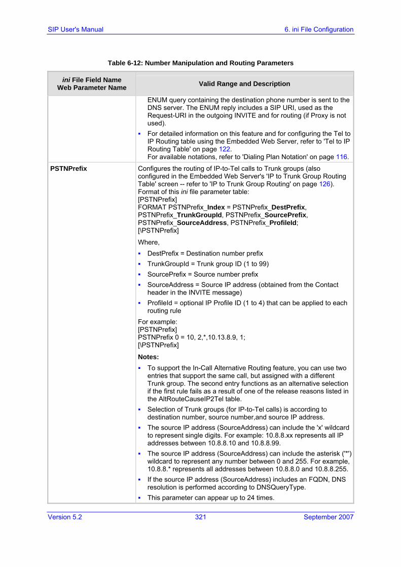
Version 5.2 321 September 2007
SIP User's Manual 6. ini File Configuration
Table 6-12: Number Manipulation and Routing Parameters
ini File Field Name Web Parameter Name Valid Range and Description
ENUM query containing the destination phone number is sent to the DNS server. The ENUM reply includes a SIP URI, used as the Request-URI in the outgoing INVITE and for routing (if Proxy is not used).
For detailed information on this feature and for configuring the Tel to IP Routing table using the Embedded Web Server, refer to 'Tel to IP Routing Table' on page 122. For available notations, refer to 'Dialing Plan Notation' on page 116.
PSTNPrefix Configures the routing of IP-to-Tel calls to Trunk groups (also configured in the Embedded Web Server's 'IP to Trunk Group Routing Table' screen -- refer to 'IP to Trunk Group Routing' on page 126). Format of this ini file parameter table: [PSTNPrefix] FORMAT PSTNPrefix_Index = PSTNPrefix_DestPrefix, PSTNPrefix_TrunkGroupId, PSTNPrefix_SourcePrefix, PSTNPrefix_SourceAddress, PSTNPrefix_ProfileId; [\PSTNPrefix]
Where, DestPrefix = Destination number prefix TrunkGroupId = Trunk group ID (1 to 99) SourcePrefix = Source number prefix SourceAddress = Source IP address (obtained from the Contact
header in the INVITE message) ProfileId = optional IP Profile ID (1 to 4) that can be applied to each
routing rule For example: [PSTNPrefix] PSTNPrefix 0 = 10, 2,*,10.13.8.9, 1; [\PSTNPrefix]
Notes: To support the In-Call Alternative Routing feature, you can use two
entries that support the same call, but assigned with a different Trunk group. The second entry functions as an alternative selection if the first rule fails as a result of one of the release reasons listed in the AltRouteCauseIP2Tel table.
Selection of Trunk groups (for IP-to-Tel calls) is according to destination number, source number,and source IP address.
The source IP address (SourceAddress) can include the 'x' wildcard to represent single digits. For example: 10.8.8.xx represents all IP addresses between 10.8.8.10 and 10.8.8.99.
The source IP address (SourceAddress) can include the asterisk ('*') wildcard to represent any number between 0 and 255. For example, 10.8.8.* represents all addresses between 10.8.8.0 and 10.8.8.255.
If the source IP address (SourceAddress) includes an FQDN, DNS resolution is performed according to DNSQueryType.
This parameter can appear up to 24 times.

SIP User's Manual 322 Document #: LTRT-68806
Mediant 2000 & TP-1610 & TP-260/UNI
Table 6-12: Number Manipulation and Routing Parameters
ini File Field Name Web Parameter Name Valid Range and Description
For available notations that represent multiple numbers, refer to 'Dialing Plan Notation' on page 116.
RemovePrefix For a description of this parameter, refer to 'General Parameters' on page 120.
RouteModeIP2Tel For a description of this parameter, refer to 'IP to Trunk Group Routing' on page 126.
RouteModeTel2IP For a description of this parameter, refer to 'Tel to IP Routing Table' on page 122.
SwapRedirectNumber For a description of this parameter, refer to 'Configuring the Digital Gateway Parameters' on page 142.
Prefix2RedirectNumber For a description of this parameter, refer to 'Configuring the Digital Gateway Parameters' on page 142.
AddTON2RPI For a description of this parameter, refer to 'General Parameters' on page 72.
NumberMapTel2IP
Manipulates the destination number for Tel-to-IP calls (also configured in the Embedded Web Server's 'Destination Phone Number Manipulation Table for Tel IP Calls'screen -- refer to 'Configuring the Number Manipulation Tables' on page 113). Format of this ini file parameter table: [NumberMapTel2Ip] FORMAT NumberMapTel2Ip_Index = NumberMapTel2Ip_DestinationPrefix, NumberMapTel2Ip_SourcePrefix, NumberMapTel2Ip_SourceAddress, NumberMapTel2Ip_NumberType, NumberMapTel2Ip_NumberPlan, NumberMapTel2Ip_RemoveFromLeft, NumberMapTel2Ip_RemoveFromRight, NumberMapTel2Ip_LeaveFromRight, NumberMapTel2Ip_Prefix2Add, NumberMapTel2Ip_Suffix2Add, NumberMapTel2Ip_IsPresentationRestricted; [\NumberMapTel2Ip]
Where, DestinationPrefix = Destination number prefix SourcePrefix = Source number prefix SourceAddress = N/A NumberType = Number Type used in RPID header NumberPlan = Number Type used in RPID header RemoveFromLeft = Number of stripped digits from the left RemoveFromRight = Number of stripped digits from the right LeaveFromRight = Number of remaining digits from the right Prefix2Add = String to add as prefix Suffix2Add = String to add as suffix IsPresentationRestricted = N/A (set to $$)
For example:

Version 5.2 323 September 2007
SIP User's Manual 6. ini File Configuration
Table 6-12: Number Manipulation and Routing Parameters
ini File Field Name Web Parameter Name Valid Range and Description
[NumberMapTel2Ip] NumberMapTel2Ip 0 = 01,$$,*,0,0,2,$$,$$,971,$$,$$; NumberMapTel2Ip 1 = 10,10,*,255,255,3,0,5,100,$$,255; [\NumberMapTel2Ip]
Notes: For a description on ini file parameter tables, refer to 'Structure of ini
File Parameter Tables' on page 269. RemoveFromLeft, RemoveFromRight, Prefix2Add, Suffix2Add,
LeaveFromRight, NumberType, and NumberPlan are applied if the called and calling numbers match the DestinationPrefix and SourcePrefix conditions.
The manipulation rules are executed in the following order: RemoveFromLeft, RemoveFromRight, LeaveFromRight, Prefix2Add, and Suffix2Add.
Parameters can be skipped by using two dollar signs ('$$'). Number Plan and Type can optionally be used in Remote Party ID
(RPID) header by using the EnableRPIHeader and AddTON2RPI parameters.
NumberMapIP2Tel Manipulates the destination number for IP-to-Tel calls (also configured in the Embedded Web Server's 'Destination Phone Number Manipulation Table for IP Tel Calls' screen -- refer to 'Configuring the Number Manipulation Tables' on page 113). Format of this ini file parameter table: [NumberMapIp2Tel] FORMAT NumberMapIp2Tel_Index = NumberMapIp2Tel_DestinationPrefix, NumberMapIp2Tel_SourcePrefix, NumberMapIp2Tel_SourceAddress, NumberMapIp2Tel_NumberType, NumberMapIp2Tel_NumberPlan, NumberMapIp2Tel_RemoveFromLeft, NumberMapIp2Tel_RemoveFromRight, NumberMapIp2Tel_LeaveFromRight, NumberMapIp2Tel_Prefix2Add, NumberMapIp2Tel_Suffix2Add, NumberMapIp2Tel_IsPresentationRestricted; [\NumberMapIp2Tel]
Where, DestinationPrefix = Destination number prefix SourcePrefix = Source number prefix SourceAddress = Source IP address (obtained from the Contact
header in the INVITE message) NumberType = Q.931 Number Type (TON) NumberPlan = Q.931 Number Plan (NPI) RemoveFromLeft = Number of stripped digits from the left RemoveFromRight = Number of stripped digits from the right LeaveFromRight = Number of remaining digits from the right

SIP User's Manual 324 Document #: LTRT-68806
Mediant 2000 & TP-1610 & TP-260/UNI
Table 6-12: Number Manipulation and Routing Parameters
ini File Field Name Web Parameter Name Valid Range and Description
Prefix2Add = String to add as prefix Suffix2Add = String to add as suffix IsPresentationRestricted = N/A (set to $$)
For example: [NumberMapIp2Tel] NumberMapIp2Tel 0 = 01,034,10.13.77.8,$$,0,$$,2,$$,667,$$; NumberMapIp2Tel 1 = 10,10,1.1.1.1,255,255,3,0,5,100,$$,255; [\NumberMapIp2Tel]
Notes: For a description on ini file parameter tables, refer to 'Structure of ini
File Parameter Tables' on page 269. RemoveFromLeft, RemoveFromRight, Prefix2Add, Suffix2Add,
LeaveFromRight, NumberType, and NumberPlan are applied if the called and calling numbers match the DestinationPrefix, SourcePrefix, and SourceAddress conditions.
The manipulation rules are executed in the following order: RemoveFromLeft, RemoveFromRight, LeaveFromRight, Prefix2Add, and Suffix2Add.
Parameters can be skipped by using two dollar signs ('$$'). The Source IP address can include the 'x' wildcard to represent
single digits. For example: 10.8.8.xx represents all addresses between 10.8.8.10 and 10.8.8.99.
The Source IP address can include the asterisk ('*') wildcard to represent any number between 0 and 255. For example, 10.8.8.* represents all the addresses between 10.8.8.0 and 10.8.8.255.
SourceNumberMapTel2IP Manipulates the source phone number for Tel-to-IP calls.(also configured in the Embedded Web Server's Source Phone Number Manipulation Table for Tel IP Calls' screen -- refer to 'Configuring the Number Manipulation Tables' on page 113). Format of this ini file parameter table: [SourceNumberMapTel2Ip] FORMAT SourceNumberMapTel2Ip_Index = SourceNumberMapTel2Ip_DestinationPrefix, SourceNumberMapTel2Ip_SourcePrefix, SourceNumberMapTel2Ip_SourceAddress, SourceNumberMapTel2Ip_NumberType, SourceNumberMapTel2Ip_NumberPlan, SourceNumberMapTel2Ip_RemoveFromLeft, SourceNumberMapTel2Ip_RemoveFromRight, SourceNumberMapTel2Ip_LeaveFromRight, SourceNumberMapTel2Ip_Prefix2Add, SourceNumberMapTel2Ip_Suffix2Add, SourceNumberMapTel2Ip_IsPresentationRestricted; [\SourceNumberMapTel2Ip]
Where, DestinationPrefix = Destination number prefix SourcePrefix = Source number prefix

Version 5.2 325 September 2007
SIP User's Manual 6. ini File Configuration
Table 6-12: Number Manipulation and Routing Parameters
ini File Field Name Web Parameter Name Valid Range and Description
SourceAddress = Source IP address (obtained from the Request-URI in the INVITE message)
NumberType = Number Type used in RPID header NumberPlan = Number Plan used in RPID header RemoveFromLeft = Number of stripped digits from the left RemoveFromRight = Number of stripped digits from the right LeaveFromRight = Number of remaining digits from the right Prefix2Add = String to add as prefix Suffix2Add = String to add as suffix IsPresentationRestricted = Calling number presentation (0 to allow
presentation; 1 to restrict presentation) For example: [SourceNumberMapTel2Ip] SourceNumberMapTel2Ip 0 = 22,03,$$,0,0,$$,2,$$,667,$$,0; SourceNumberMapTel2Ip 0 = 10,10,*,255,255,3,0,5,100,$$,255; [\SourceNumberMapTel2Ip]
Notes: For a description on ini file parameter tables, refer to 'Structure of ini
File Parameter Tables' on page 269. RemoveFromLeft, RemoveFromRight, Prefix2Add, Suffix2Add,
LeaveFromRight, NumberType, NumberPlan, and IsPresentationRestricted are applied if the called and calling numbers match the DestinationPrefix and SourcePrefix conditions.
The manipulation rules are executed in the following order: RemoveFromLeft, RemoveFromRight, LeaveFromRight, Prefix2Add, and Suffix2Add.
Parameters can be skipped by using two dollar signs ('$$'). An asterisk ('*') represents all IP addresses. IsPresentationRestricted is set to 'Restricted' only if 'Asserted
Identity Mode' is set to 'P-Asserted'. Number Plan and Type can optionally be used in Remote Party ID
(RPID) header by using the EnableRPIHeader and AddTON2RPI parameters.
SourceNumberMapIP2Tel Manipulates the source number for IP-to-Tel calls (also configured in the Embedded Web Server's 'Source Phone Number Manipulation Table for IP Tel Calls' screen -- refer to 'Configuring the Number Manipulation Tables' on page 113). Format of this ini file parameter table: [SourceNumberMapIp2Tel] FORMAT SourceNumberMapIp2Tel_Index = SourceNumberMapIp2Tel_DestinationPrefix, SourceNumberMapIp2Tel_SourcePrefix, SourceNumberMapIp2Tel_SourceAddress, SourceNumberMapIp2Tel_NumberType, SourceNumberMapIp2Tel_NumberPlan,

SIP User's Manual 326 Document #: LTRT-68806
Mediant 2000 & TP-1610 & TP-260/UNI
Table 6-12: Number Manipulation and Routing Parameters
ini File Field Name Web Parameter Name Valid Range and Description
SourceNumberMapIp2Tel_RemoveFromLeft, SourceNumberMapIp2Tel_RemoveFromRight, SourceNumberMapIp2Tel_LeaveFromRight, SourceNumberMapIp2Tel_Prefix2Add, SourceNumberMapIp2Tel_Suffix2Add, SourceNumberMapIp2Tel_IsPresentationRestricted; [\SourceNumberMapIp2Tel]
Where, DestinationPrefix = Destination number prefix SourcePrefix = Source number prefix SourceAddress = Source IP address (obtained from the Request-
URI in the INVITE message) NumberType = Q.931 Number Type (TON) NumberPlan = Q.931 Number Plan (NPI) RemoveFromLeft = Number of stripped digits from the left RemoveFromRight = Number of stripped digits from the right LeaveFromRight = Number of remaining digits from the right Prefix2Add = String to add as prefix Suffix2Add = String to add as suffix IsPresentationRestricted = Calling number presentation (0 to allow
presentation; 1 to restrict presentation) For example: [SourceNumberMapIp2Tel] SourceNumberMapIp2Tel 0 = 22,03,$$,$$,$$,$$,2,667,$$,$$;SourceNumberMapIp2Tel 1 = 034,01,1.1.1.1,$$,0,2,$$,$$,972,$$,10; [\SourceNumberMapIp2Tel]
Notes: For a description on ini file parameter tables, refer to 'Structure of ini
File Parameter Tables' on page 269. RemoveFromLeft, RemoveFromRight, Prefix2Add, Suffix2Add,
LeaveFromRight, NumberType, and NumberPlan are applied if the called and calling numbers match the DestinationPrefix, SourcePrefix, and SourceAddress conditions.
The manipulation rules are executed in the following order: RemoveFromLeft, RemoveFromRight, LeaveFromRight, Prefix2Add, and Suffix2Add.
Parameters can be skipped by using two dollar signs ('$$'). The Source IP address can include the 'x' wildcard to represent
single digits. For example: 10.8.8.xx represents all addresses between 10.8.8.10 and 10.8.8.99.
The Source IP address can include the asterisk ('*') wildcard to represent any number between 0 and 255. For example, 10.8.8.* represents all the addresses between 10.8.8.0 and 10.8.8.255.

Version 5.2 327 September 2007
SIP User's Manual 6. ini File Configuration
Table 6-12: Number Manipulation and Routing Parameters
ini File Field Name Web Parameter Name Valid Range and Description
For ETSI ISDN variant, the following Number Plan and Type combinations (Plan/Type) are supported in the Destination and Source Manipulation tables: 0,0 = Unknown, Unknown 9,0 = Private, Unknown 9,1 = Private, Level 2 Regional 9,2 = Private, Level 1 Regional 9,3 = Private, PISN Specific 9,4 = Private, Level 0 Regional (local) 1,0 = Public(ISDN/E.164), Unknown 1,1 = Public(ISDN/E.164), International 1,2 = Public(ISDN/E.164), National 1,3 = Public(ISDN/E.164), Network Specific 1,4 = Public(ISDN/E.164), Subscriber 1,6 = Public(ISDN/E.164), Abbreviated
For NI-2 and DMS-100 ISDN variants the valid combinations of TON and NPI for calling and called numbers are (Plan/Type): 0/0 - Unknown/Unknown 1/1 - International number in ISDN/Telephony numbering plan 1/2 - National number in ISDN/Telephony numbering plan 1/4 - Subscriber (local) number in ISDN/Telephony numbering plan 9/4 - Subscriber (local) number in Private numbering plan
SecureCallsFromIP For a description of this parameter, refer to 'General Parameters' on page 103.

SIP User's Manual 328 Document #: LTRT-68806
Mediant 2000 & TP-1610 & TP-260/UNI
Table 6-12: Number Manipulation and Routing Parameters
ini File Field Name Web Parameter Name Valid Range and Description
AltRouteCauseTel2IP Table of SIP call failure reason values received from the IP side. If a call is released as a result of one of these reasons, the gateway tries to find an alternative route to that call in the 'Tel to IP Routing' table (if Proxy is not used) or used as a redundant Proxy (when Proxy is used). Format for this ini file parameter table: [AltRouteCauseTel2IP] FORMAT AltRouteCauseTel2IP_Index = AltRouteCauseTel2IP_ReleaseCause; [\AltRouteCauseTel2IP]
For example: [AltRouteCauseTel2IP] AltRouteCauseTel2IP 0 = 486; (Busy here) AltRouteCauseTel2IP 1 = 480; (Temporarily unavailable) AltRouteCauseTel2IP 2 = 408; (No response) [\AltRouteCauseTel2IP]
Notes: For an explanation on ini file parameter tables, refer to 'Structure of
ini File Parameter Tables' on page 269. The 408 reason can be used to specify no response from the remote
party to the INVITE request. This parameter can appear up to 5 times. For defining the Reasons for Alternative Routing table using the
Embedded Web Server, refer to 'Reasons for Alternative Routing' on page 130.

Version 5.2 329 September 2007
SIP User's Manual 6. ini File Configuration
Table 6-12: Number Manipulation and Routing Parameters
ini File Field Name Web Parameter Name Valid Range and Description
AltRouteCauseIP2Tel Table of call failure reason values received from the PSTN side (in Q.931 presentation). If a call is released as a result of one of these reasons, the gateway attempts to find an alternative trunk group for that call in the 'IP to Trunk Group Routing' table.
Format for this ini file parameter table: [AltRouteCauseIP2Tel] FORMAT AltRouteCauseIP2Tel_Index = AltRouteCauseIP2Tel_ReleaseCause; [\AltRouteCauseIP2Tel]
For example: [AltRouteCauseIP2Tel] AltRouteCauseIP2Tel 0 = 3 (No route to destination) AltRouteCauseIP2Tel 1 = 1 (Unallocated number) AltRouteCauseIP2Tel 2 = 17 (Busy here) [\AltRouteCauseIP2Tel]
Notes: For an explanation on ini file parameter tables, refer to 'Structure of
ini File Parameter Tables' on page 269. This parameter can appear up to 5 times. If the gateway fails to establish a call to the PSTN because it has no
available channels in a specific trunk group (e.g., all trunk group's channels are occupied, or the trunk group's spans are disconnected or out of sync), it uses the Internal Release Cause '3' (no route to destination). This cause can be used in the AltRouteCauseIP2Tel table to define routing to an alternative trunk group.
For defining the Reasons for Alternative Routing table using the Embedded Web Server, refer to 'Reasons for Alternative Routing' on page 130.
EnableETSIDiversion Defines the method in which the Redirect Number is passed towards the Tel side. Valid options include: [0] = Q.931 Redirecting Number Information Element (default) [1] = ETSI DivertingLegInformation2 in a Facility Information
Element
FilterCalls2IP For a description of this parameter, refer to 'General Parameters' on page 103.
Alternative Routing Parameters
RedundantRoutingMode Determines the type of redundant routing mechanism to implement when a call can’t be completed using the main route. [0] = No redundant routing is used. If the call can’t be completed
using the main route (either using the active Proxy or the first matching rule in the internal routing table), the call is disconnected.
[1] = Internal routing table is used to find a redundant route (default). [2] = Proxy list is used to find a redundant route.

SIP User's Manual 330 Document #: LTRT-68806
Mediant 2000 & TP-1610 & TP-260/UNI
Table 6-12: Number Manipulation and Routing Parameters
ini File Field Name Web Parameter Name Valid Range and Description
AltRoutingTel2IPEnable For a description of this parameter, refer to 'General Parameters' on page 120.
AltRoutingTel2IPMode For a description of this parameter, refer to 'General Parameters' on page 120.
IPConnQoSMaxAllowedPL For a description of this parameter, refer to 'General Parameters' on page 120.
IPConnQoSMaxAllowedDelay
For a description of this parameter, refer to 'General Parameters' on page 120.
Phone-Context Parameters
AddPhoneContextAsPrefix
For a description of this parameter, refer to 'Mapping NPI/TON to Phone-Context' on page 118.

Version 5.2 331 September 2007
SIP User's Manual 6. ini File Configuration
Table 6-12: Number Manipulation and Routing Parameters
ini File Field Name Web Parameter Name Valid Range and Description
PhoneContext Defines the Phone Context table. Format for this ini file parameter table: [PhoneContext] FORMAT PhoneContext_Index = PhoneContext_Npi, PhoneContext_Ton, PhoneContext_Context; [\PhoneContext]
Where, Npi = Number Plan Ton = Number Type Context = Phone-Context value
When a call is received from the ISDN, the NPI and TON are compared against the table, and the Phone-Context value is used in the outgoing SIP INVITE message. The same mapping occurs when an INVITE with a Phone-Context attribute is received. The Phone-Context parameter appears in the standard SIP headers where a phone number is used (Request-URI, To, From, Diversion).
For example: [PhoneContext] PhoneContext 0 = 0,0,unknown.com PhoneContext 1 = 1,1,host.com PhoneContext 2 = 9,1,na.e164.host.com [\PhoneContext]
Notes: For an explanation on ini file parameter tables, refer to 'Structure of
ini File Parameter Tables' on page 269. This parameter can appear up to 20 times. Several entries with the same NPI-TON or Phone-Context are
allowed. In this scenario, a Tel-to-IP call uses the first match. Phone-Context '+' is a unique as it doesn't appear in the Request-
URI as a Phone-Context parameter. Instead, it's added as a prefix to the phone number. The '+' isn't removed from the phone number in the IP-to-Tel direction.
To configure Phone Context table using the Embedded Web Server, refer to 'Mapping NPI/TON to Phone-Context' on page 118.

SIP User's Manual 332 Document #: LTRT-68806
Mediant 2000 & TP-1610 & TP-260/UNI
6.5.13 Channel Parameters The Channel Parameters define the DTMF, fax and modem transfer modes.
Table 6-13: Channel Parameters
ini File Field Name Web Parameter Name Valid Range and Description
DSPVersionTemplateNumber For a description of this parameter, refer to 'Configuring the General Media Settings' on page 177.
DJBufMinDelay For a description of this parameter, refer to 'Configuring the RTP / RTCP Settings' on page 172.
DJBufOptFactor For a description of this parameter, refer to 'Configuring the RTP / RTCP Settings' on page 172.
FaxTransportMode For a description of this parameter, refer to 'Configuring the Fax / Modem / CID Settings' on page 168.
FaxRelayEnhancedRedundancyDepth
For a description of this parameter, refer to 'Configuring the Fax / Modem / CID Settings' on page 168.
FaxRelayRedundancyDepth For a description of this parameter, refer to 'Configuring the Fax / Modem / CID Settings' on page 168.
FaxRelayMaxRate For a description of this parameter, refer to 'Configuring the Fax / Modem / CID Settings' on page 168.
FaxRelayECMEnable For a description of this parameter, refer to 'Configuring the Fax / Modem / CID Settings' on page 168.
FaxModemBypassCoderType For a description of this parameter, refer to 'Configuring the Fax / Modem / CID Settings' on page 168.
CNGDetectorMode For a description of this parameter, refer to 'Configuring the Fax / Modem / CID Settings' on page 168.
FaxModemBypassM For a description of this parameter, refer to 'Configuring the Fax / Modem / CID Settings' on page 168.
FaxBypassPayloadType For a description of this parameter, refer to 'Configuring the RTP / RTCP Settings' on page 172.
CallerIDTransportType For a description of this parameter, refer to 'Configuring the Fax / Modem / CID Settings' on page 168.
ModemBypassPayloadType Modem Bypass dynamic payload type (range 0-127). The default value is 103.
DetFaxOnAnswerTone For a description of this parameter, refer to 'General Parameters' on page 72.
EchoCancellerAggressiveNLP Enables or disables the Aggressive NLP at the first 0.5 second of the call. When enabled, the echo is removed only in the first half a second of the incoming IP signal. [0] = Disable (default) [1] = Enable

Version 5.2 333 September 2007
SIP User's Manual 6. ini File Configuration
Table 6-13: Channel Parameters
ini File Field Name Web Parameter Name Valid Range and Description
FaxModemBypassBasicRTPPacketInterval
Determines the basic frame size that is used during fax / modem bypass sessions. [0] = Determined internally (default) [1] = 5 msec (not recommended) [2] = 10 msec [3] = 20 msec
Note: When set for 5 msec (1), the maximum number of simultaneous channels supported is 120.
FaxModemBypassDJBufMinDelay
Determines the Jitter Buffer delay during fax and modem bypass session. The range is 0 to 150 msec. The default is 40.
EnableFaxModemInbandNetworkDetection
Enables or disables inband network detection related to fax/modem. [0] = Disable (default) [1] = Enable
When this parameter is enabled on Bypass mode (VxxTransportType = 2), a detection of an Answer Tone from the network triggers a switch to bypass mode in addition to the local Fax/Modem tone detections. However, only a high bit-rate coder voice session effectively detects the Answer Tone sent by a remote Endpoint. This can be useful when, for example, the payload of voice and bypass is the same, allowing the originator to switch to bypass mode as well.
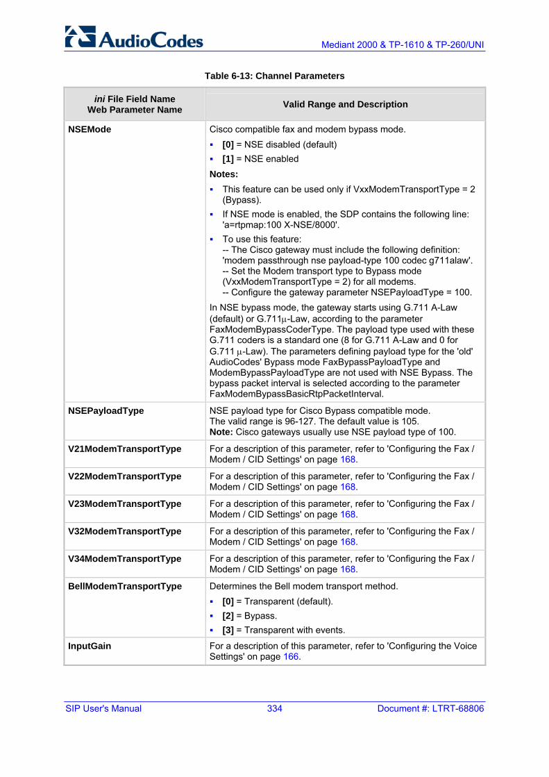
SIP User's Manual 334 Document #: LTRT-68806
Mediant 2000 & TP-1610 & TP-260/UNI
Table 6-13: Channel Parameters
ini File Field Name Web Parameter Name Valid Range and Description
NSEMode Cisco compatible fax and modem bypass mode. [0] = NSE disabled (default) [1] = NSE enabled
Notes: This feature can be used only if VxxModemTransportType = 2
(Bypass). If NSE mode is enabled, the SDP contains the following line:
'a=rtpmap:100 X-NSE/8000'. To use this feature:
-- The Cisco gateway must include the following definition: 'modem passthrough nse payload-type 100 codec g711alaw'. -- Set the Modem transport type to Bypass mode (VxxModemTransportType = 2) for all modems. -- Configure the gateway parameter NSEPayloadType = 100.
In NSE bypass mode, the gateway starts using G.711 A-Law (default) or G.711µ-Law, according to the parameter FaxModemBypassCoderType. The payload type used with these G.711 coders is a standard one (8 for G.711 A-Law and 0 for G.711 µ-Law). The parameters defining payload type for the 'old' AudioCodes' Bypass mode FaxBypassPayloadType and ModemBypassPayloadType are not used with NSE Bypass. The bypass packet interval is selected according to the parameter FaxModemBypassBasicRtpPacketInterval.
NSEPayloadType NSE payload type for Cisco Bypass compatible mode. The valid range is 96-127. The default value is 105. Note: Cisco gateways usually use NSE payload type of 100.
V21ModemTransportType For a description of this parameter, refer to 'Configuring the Fax / Modem / CID Settings' on page 168.
V22ModemTransportType For a description of this parameter, refer to 'Configuring the Fax / Modem / CID Settings' on page 168.
V23ModemTransportType For a description of this parameter, refer to 'Configuring the Fax / Modem / CID Settings' on page 168.
V32ModemTransportType For a description of this parameter, refer to 'Configuring the Fax / Modem / CID Settings' on page 168.
V34ModemTransportType For a description of this parameter, refer to 'Configuring the Fax / Modem / CID Settings' on page 168.
BellModemTransportType Determines the Bell modem transport method. [0] = Transparent (default). [2] = Bypass. [3] = Transparent with events.
InputGain For a description of this parameter, refer to 'Configuring the Voice Settings' on page 166.
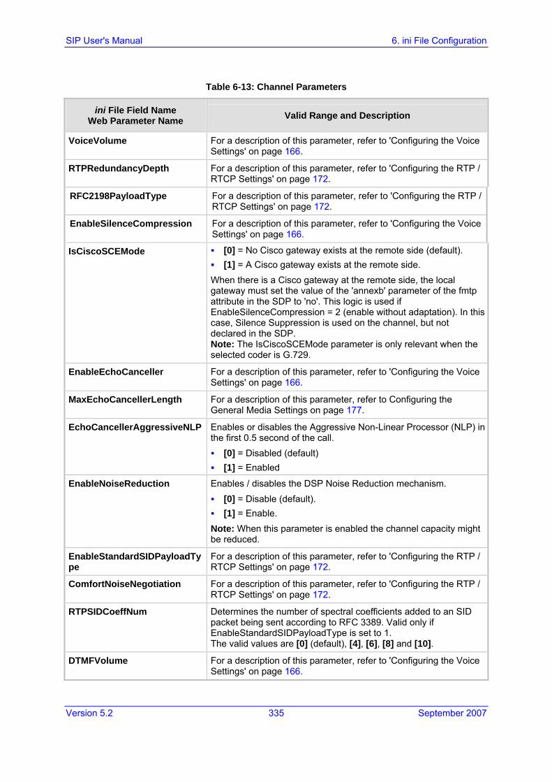
Version 5.2 335 September 2007
SIP User's Manual 6. ini File Configuration
Table 6-13: Channel Parameters
ini File Field Name Web Parameter Name Valid Range and Description
VoiceVolume For a description of this parameter, refer to 'Configuring the Voice Settings' on page 166.
RTPRedundancyDepth For a description of this parameter, refer to 'Configuring the RTP / RTCP Settings' on page 172.
RFC2198PayloadType For a description of this parameter, refer to 'Configuring the RTP / RTCP Settings' on page 172.
EnableSilenceCompression For a description of this parameter, refer to 'Configuring the Voice Settings' on page 166.
IsCiscoSCEMode [0] = No Cisco gateway exists at the remote side (default). [1] = A Cisco gateway exists at the remote side.
When there is a Cisco gateway at the remote side, the local gateway must set the value of the 'annexb' parameter of the fmtp attribute in the SDP to 'no'. This logic is used if EnableSilenceCompression = 2 (enable without adaptation). In this case, Silence Suppression is used on the channel, but not declared in the SDP. Note: The IsCiscoSCEMode parameter is only relevant when the selected coder is G.729.
EnableEchoCanceller For a description of this parameter, refer to 'Configuring the Voice Settings' on page 166.
MaxEchoCancellerLength For a description of this parameter, refer to Configuring the General Media Settings on page 177.
EchoCancellerAggressiveNLP Enables or disables the Aggressive Non-Linear Processor (NLP) in the first 0.5 second of the call. [0] = Disabled (default) [1] = Enabled
EnableNoiseReduction Enables / disables the DSP Noise Reduction mechanism. [0] = Disable (default). [1] = Enable.
Note: When this parameter is enabled the channel capacity might be reduced.
EnableStandardSIDPayloadType
For a description of this parameter, refer to 'Configuring the RTP / RTCP Settings' on page 172.
ComfortNoiseNegotiation For a description of this parameter, refer to 'Configuring the RTP / RTCP Settings' on page 172.
RTPSIDCoeffNum Determines the number of spectral coefficients added to an SID packet being sent according to RFC 3389. Valid only if EnableStandardSIDPayloadType is set to 1. The valid values are [0] (default), [4], [6], [8] and [10].
DTMFVolume For a description of this parameter, refer to 'Configuring the Voice Settings' on page 166.
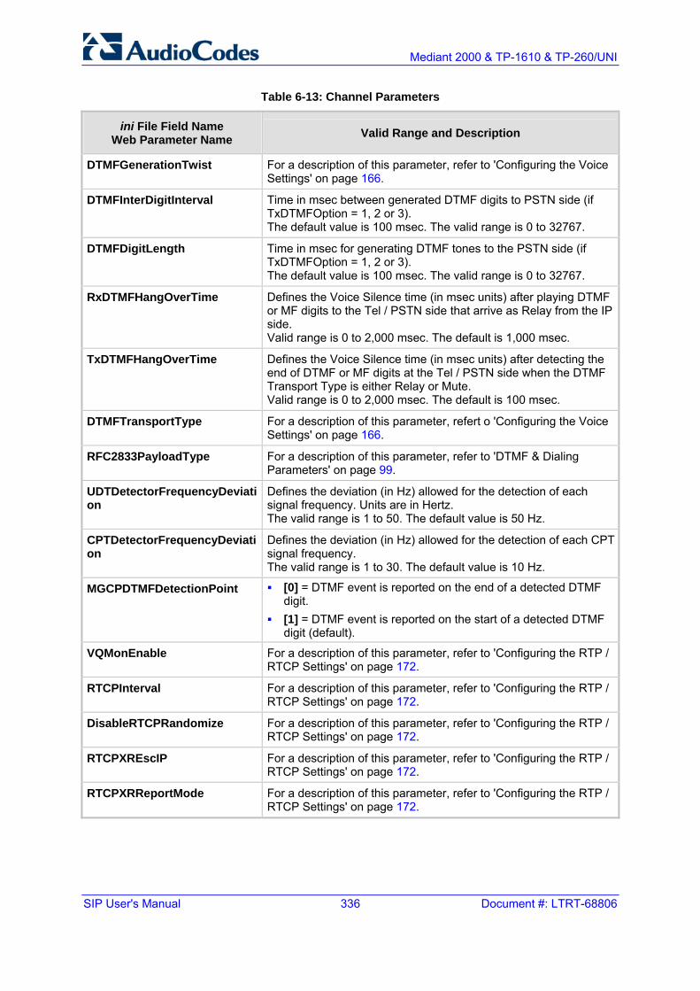
SIP User's Manual 336 Document #: LTRT-68806
Mediant 2000 & TP-1610 & TP-260/UNI
Table 6-13: Channel Parameters
ini File Field Name Web Parameter Name Valid Range and Description
DTMFGenerationTwist For a description of this parameter, refer to 'Configuring the Voice Settings' on page 166.
DTMFInterDigitInterval Time in msec between generated DTMF digits to PSTN side (if TxDTMFOption = 1, 2 or 3). The default value is 100 msec. The valid range is 0 to 32767.
DTMFDigitLength Time in msec for generating DTMF tones to the PSTN side (if TxDTMFOption = 1, 2 or 3). The default value is 100 msec. The valid range is 0 to 32767.
RxDTMFHangOverTime Defines the Voice Silence time (in msec units) after playing DTMF or MF digits to the Tel / PSTN side that arrive as Relay from the IP side. Valid range is 0 to 2,000 msec. The default is 1,000 msec.
TxDTMFHangOverTime Defines the Voice Silence time (in msec units) after detecting the end of DTMF or MF digits at the Tel / PSTN side when the DTMF Transport Type is either Relay or Mute. Valid range is 0 to 2,000 msec. The default is 100 msec.
DTMFTransportType For a description of this parameter, refert o 'Configuring the Voice Settings' on page 166.
RFC2833PayloadType For a description of this parameter, refer to 'DTMF & Dialing Parameters' on page 99.
UDTDetectorFrequencyDeviation
Defines the deviation (in Hz) allowed for the detection of each signal frequency. Units are in Hertz. The valid range is 1 to 50. The default value is 50 Hz.
CPTDetectorFrequencyDeviation
Defines the deviation (in Hz) allowed for the detection of each CPT signal frequency. The valid range is 1 to 30. The default value is 10 Hz.
MGCPDTMFDetectionPoint [0] = DTMF event is reported on the end of a detected DTMF digit.
[1] = DTMF event is reported on the start of a detected DTMF digit (default).
VQMonEnable For a description of this parameter, refer to 'Configuring the RTP / RTCP Settings' on page 172.
RTCPInterval For a description of this parameter, refer to 'Configuring the RTP / RTCP Settings' on page 172.
DisableRTCPRandomize For a description of this parameter, refer to 'Configuring the RTP / RTCP Settings' on page 172.
RTCPXREscIP For a description of this parameter, refer to 'Configuring the RTP / RTCP Settings' on page 172.
RTCPXRReportMode For a description of this parameter, refer to 'Configuring the RTP / RTCP Settings' on page 172.

Version 5.2 337 September 2007
SIP User's Manual 6. ini File Configuration
6.5.14 Configuration Files Parameters The configuration files (i.e., auxiliary files) can be loaded to the gateway using the Embedded Web Server or a TFTP session (refer to 'Auxiliary Files' on page 247). Before you load them to the gateway, in the ini file you need to specify the files that you want loaded and whether they must be stored in the non-volatile memory. The table below lists the ini file parameters associated with these configuration files:
Table 6-14: Configuration Files Parameters
ini File Field Name Valid Range and Description
CallProgressTonesFilename The name of the file containing the Call Progress Tones definitions. Refer to the SIP Series Reference Manual for additional information on how to create and load this file.
CASFileName This is the name of the file containing specific CAS protocol definition (such as 'E_M_WinkTable.dat'). These files are provided to support various types of CAS signaling.
CASFileName_x CAS file name (e.g., 'E_M_WinkTable.dat') that defines the CAS protocol. It is possible to define up to eight different CAS files by repeating this parameter. Each CAS file can be associated with one or more of the gateway trunks using the parameter CASTableIndex_x.
CASTablesNum Number, 1 to 8. Specifies how many CAS configuration files are loaded.
VoicePromptsFileName The name (and path) of the file containing the Voice Prompts definitions. Refer to the SIP Series Reference Manual for additional information on how to create and load this file.
PrerecordedTonesFileName The name (and path) of the file containing the Prerecorded Tones.
CasTrunkDialPlanName The Dial Plan name (up to 11-character strings) that is used on the specific trunk.
DialPlanFileName The name (and path) of the file containing dial-plan configuration for CAS and SIP protocols. This file should be constructed using the TrunkPack Conversion Utility (refer to the SIP Series Reference Manual) supplied as part of the software package on the CD accompanying the gateway.
UserInfoFileName The name (and path) of the file containing the User Information data.
SaveConfiguration Determines if the gateway's configuration (parameters and files) is saved to flash (non-volatile memory). [0] = Configuration isn't saved to flash memory. [1] = Configuration is saved to flash memory (default).

SIP User's Manual 338 Document #: LTRT-68806
Mediant 2000 & TP-1610 & TP-260/UNI
Reader's Notes

Version 5.2 339 September 2007
SIP User's Manual 7. Telephony Capabilities
7 Telephony Capabilities This section describes the gateway's telephony capabilities.
7.1 Configuring the DTMF Transport Types You can control the way DTMF digits are transported over the IP network to the remote endpoint. The following five modes are supported:
Using INFO message according to the Nortel IETF draft: In this mode DTMF digits are carried to the remote side within INFO messages. To enable this mode, define the following:
• RxDTMFOption = 0 (Protocol Management menu > Protocol Definition submenu > DTMF & Dialing option > 'Declare RFC 2833 in SDP' = No)
• TxDTMFOption = 1 (1st to 5th DTMF Option = INFO (Nortel))
Note that in this mode, DTMF digits are erased from the audio stream [DTMFTransportType is automatically set to 0 (DTMF Mute)].
Using INFO message according to Cisco’s mode: In this mode, DTMF digits are carried to the remote side within INFO messages. To enable this mode, define the following:
• RxDTMFOption = 0 (Declare RFC 2833 in SDP = No)
• TxDTMFOption = 3 (1st to 5th DTMF Option = INFO (Cisco))
Note that in this mode, DTMF digits are erased from the audio stream (DTMFTransportType is automatically set to 0 (DTMF Mute)).
Using NOTIFY messages according to <draft-mahy-sipping-signaled-digits-01.txt>: In this mode, DTMF digits are carried to the remote side using NOTIFY messages. To enable this mode, define the following:
• RxDTMFOption = 0 (Declare RFC 2833 in SDP = No)
• TxDTMFOption = 2 (1st to 5th DTMF Option = NOTIFY)
Note that in this mode, DTMF digits are erased from the audio stream (DTMFTransportType is automatically set to 0 (DTMF Mute)).
Using RFC 2833 relay with Payload type negotiation: In this mode, DTMF digits are carried to the remote side as part of the RTP stream in accordance with RFC 2833 standard. To enable this mode, define the following:
• TxDTMFOption = 4 (1st to 5th DTMF Option = RFC 2833)
• RxDTMFOption = 3 (Declare RFC 2833 in SDP = Yes)
Note that to set the RFC 2833 payload type with a different value (other than its default, 96) configure the RFC2833PayloadType (RFC 2833 Payload Type) parameter. The gateway negotiates the RFC 2833 payload type using local and remote SDP and sends packets using the PT from the received SDP. The gateway expects to receive RFC 2833 packets with the same PT as configured by the RFC2833PayloadType parameter. If the remote side doesn’t include ‘telephony-event’ in its SDP, the gateway sends DTMF digits in transparent mode (as part of the voice stream).

SIP User's Manual 340 Document #: LTRT-68806
Mediant 2000 & TP-1610 & TP-260/UNI
Sending DTMF digits (in RTP packets) as part of the audio stream (DTMF Relay is disabled): Note that this method is normally used with G.711 coders; with other low-bit rate (LBR) coders the quality of the DTMF digits is reduced. To enable this mode, define the following:
• TxDTMFOption = 0 (1st to 5th DTMF Option = Disable)
• RxDTMFOption = 0 (Declare RFC 2833 in SDP = No)
• DTMFTransportType = 2 (DTMF Transport Type = Transparent DTMF)
Using INFO message according to Korea mode: In this mode, DTMF digits are carried to the remote side within INFO messages. To enable this mode, define the following:
• RxDTMFOption = 0 (Declare RFC 2833 in SDP = No)
• TxDTMFOption = 3 (1st to 5th DTMF Option = INFO (Korea))
• Note that in this mode, DTMF digits are erased from the audio stream (DTMFTransportType is automatically set to 0 (DTMF Mute)).
Notes:
• The gateway is always ready to receive DTMF packets over IP, in all possible transport modes: INFO messages, NOTIFY, and RFC 2833 (in proper payload type) or as part of the audio stream.
• To exclude RFC 2833 Telephony event parameter from the gateway's SDP, set RxDTMFOption to 0 in the ini file.
The following parameters affect the way the SIP gateway handles the DTMF digits:
TxDTMFOption, RxDTMFOption, and RFC2833PayloadType (described in 'DTMF & Dialing Parameters' on page 99)
MGCPDTMFDetectionPoint, DTMFVolume, DTMFTransportType, DTMFDigitLength, and DTMFInterDigitInterval (refer to 'Channel Parameters' on page 332)
7.2 Fax and Modem Capabilities
7.2.1 Fax/Modem Operating Modes The gateway supports two modes of operations:
Fax / modem negotiation isn’t performed during the establishment of the call.
VBD mode for V.152 implementation (refer to 'Supporting V.152 Implementation' on page 347): in this mode, fax / modem capabilities are negotiated between the gateway and the remote endpoint at the establishment of the call. During a call, when a fax / modem signal is detected, change from voice to VBD (or T.38) is automatically performed and no additional SIP signaling is required. If negotiation fails (i.e., no match is achieved for any of the transport capabilities), fallback to existing logic occurs (according to the parameter IsFaxUsed).

Version 5.2 341 September 2007
SIP User's Manual 7. Telephony Capabilities
7.2.2 Fax/Modem Transport Modes The gateway supports the following transport modes for fax and each modem type (V.22/V.23/Bell/V.32/V.34):
T.38 fax relay (refer to 'Fax Relay Mode' on page 341)
Fax and modem bypass: a proprietary method that uses a high bit rate coder (refer to 'Fax/Modem Bypass Mode' on page 342)
NSE Cisco’s Pass-through bypass mode for fax and modem (refer to 'Fax / Modem NSE Mode' on page 343)
Transparent: passing the fax / modem signal in the current voice coder (refer to 'Fax / Modem Transparent Mode' on page 345)
Transparent with events: passing the fax / modem signal in the current voice coder with adaptations (refer to 'Fax / Modem Transparent with Events Mode' on page 345)
G.711 Transport: switching to G.711 when fax/modem is detected (refer to 'G.711 Fax / Modem Transport Mode' on page 344)
Fax fallback to G.711 if T.38 is not supported (refer to 'Fax Fallback' on page 344)
‘Adaptations’ refer to automatic reconfiguration of certain DSP features to treat fax/modem streams differently than voice.
7.2.2.1 T.38 Fax Relay Mode
In this mode, fax signals are transferred using T.38 protocol. T.38 is an ITU standard for sending fax across IP networks in a real-time mode. The gateway currently supports only the T.38 UDP syntax.
T.38 can be configured in the following two ways:
Switching to T.38 mode using SIP Re-INVITE messages (refer to 'Switching to T.38 Mode using SIP Re-INVITE' on page 341)
Automatically switching to T.38 mode without using SIP Re-INVITE messages (refer to 'Automatically Switching to T.38 Mode without SIP Re-INVITE' on page 342)
When fax transmission has ended, the reverse switching from fax relay to voice is automatically performed at both the local and remote endpoints.
You can change the fax rate that is declared in the SDP using the parameter FaxRelayMaxRate (this parameter doesn’t affect the actual transmission rate) and can enable/disable Error Correction Mode (ECM) fax mode using the FaxRelayECMEnable parameter.
When using T.38 mode, you can define a redundancy feature to improve fax transmission over congested IP networks. This feature is activated using the FaxRelayRedundancyDepth and FaxRelayEnhancedRedundancyDepth parameters. Although this is a proprietary redundancy scheme, it should not create problems when working with other T.38 decoders.
7.2.2.1.1 Switching to T.38 Mode using SIP Re-INVITE
In this mode, the terminating gateway on detection of a fax signal, negotiates T.38 capabilities using a Re-INVITE message. If the far-end gateway doesn't support T.38, the fax fails.

SIP User's Manual 342 Document #: LTRT-68806
Mediant 2000 & TP-1610 & TP-260/UNI
In this mode, the parameter FaxTransportMode is ignored.
To configure T.38 mode using SIP Re-INVITE messages, set IsFaxUsed to 1. Additional configuration parameters include the following:
FaxRelayEnhancedRedundancyDepth
FaxRelayRedundancyDepth
FaxRelayECMEnable
FaxRelayMaxRate
7.2.2.1.2 Automatically Switching to T.38 Mode without SIP Re-INVITE
In this mode, when a fax signal is detected the channel automatically switches from the current voice coder to answer tone mode, and then to T.38-compliant fax relay mode.
To configure automatic T.38 mode, perform the following configurations:
IsFaxUsed = 0
FaxTransportMode = 1
Additional configuration parameters:
• FaxRelayEnhancedRedundancyDepth
• FaxRelayRedundancyDepth
• FaxRelayECMEnable
• FaxRelayMaxRate
7.2.2.2 Fax/Modem Bypass Mode
In this proprietary mode, when fax or modem signals are detected, the channel automatically switches from the current voice coder to a high bit-rate coder (according to the parameter FaxModemBypassCoderType). In addition, the channel is automatically reconfigured with the following fax / modem adaptations: switches off silence suppression, enables echo cancellation for fax and disables it for modem, and performs certain jitter buffering optimizations. The network packets generated and received during the bypass period are regular voice RTP packets (per the selected bypass coder), but with a different RTP payload type (according to the parameters FaxBypassPayloadType and ModemBypassPayloadType).
During the bypass period, the coder uses the packing factor, which is defined by the parameter FaxModemBypassM. The packing factor determines the number of coder payloads (each the size of FaxModemBypassBasicRTPPacketInterval) that are used to generate a single fax/modem bypass packet.
When fax/modem transmission ends, the reverse switching, from bypass coder to regular voice coder, is carried out.
To configure fax / modem bypass mode, perform the following configurations:
IsFaxUsed = 0
FaxTransportMode = 2
V21ModemTransportType = 2
V22ModemTransportType = 2
V23ModemTransportType = 2

Version 5.2 343 September 2007
SIP User's Manual 7. Telephony Capabilities
V32ModemTransportType = 2
V34ModemTransportType = 2
BellModemTransportType = 2
Additional configuration parameters:
• FaxModemBypassCoderType
• FaxBypassPayloadType
• ModemBypassPayloadType
• FaxModemBypassBasicRTPPacketInterval
• FaxModemBypassDJBufMinDelay
Notes: When the gateway is configured for modem bypass and T.38 fax, V.21 low-speed modems are not supported and fail as a result.
7.2.2.3 Fax / Modem NSE Mode
In this mode, fax and modem signals are transferred using Cisco-compatible Pass-through bypass mode. On detection of fax or modem answering tone signal, the terminating gateway sends three to six special NSE RTP packets (using NSEpayloadType, usually 100). These packets signal the remote gateway to switch to G.711 coder (according to the parameter FaxModemBypassCoderType). After a few NSE packets are exchanged between the gateways, both gateways start using G.711 packets with standard payload type (8 for G.711 A-Law and 0 for G.711 Mu-Law). In this mode, no Re-INVITE messages are sent. The voice channel is optimized for fax/modem transmission (same as for usual bypass mode).
The parameters defining payload type for the proprietary AudioCodes’ Bypass mode FaxBypassPayloadType and ModemBypassPayloadType are not used with NSE Bypass.
When configured for NSE mode, the gateway includes in its SDP the following line: a=rtpmap:100 X-NSE/8000
(where 100 is the NSE payload type)
The Cisco gateway must include the following definition: "modem passthrough nse payload-type 100 codec g711alaw".
To configure NSE mode, perform the following configurations:
IsFaxUsed = 0
FaxTransportMode = 2
NSEMode = 1
NSEPayloadType = 100
V21ModemTransportType = 2
V22ModemTransportType = 2
V23ModemTransportType = 2
V32ModemTransportType = 2

SIP User's Manual 344 Document #: LTRT-68806
Mediant 2000 & TP-1610 & TP-260/UNI
V34ModemTransportType = 2
BellModemTransportType = 2
7.2.2.4 G.711 Fax / Modem Transport Mode
In this mode, when the terminating gateway detects fax or modem signals (CED or AnsAM), it sends a Re-INVITE message to the originator gateway asking it to reopen the channel in G.711 VBD with the following adaptations:
Echo Canceller = off
Silence Compression = off
Echo Canceller Non-Linear Processor Mode = off
Dynamic Jitter Buffer Minimum Delay = 40
Dynamic Jitter Buffer Optimization Factor = 13
After a few seconds upon detection of fax V.21 preamble or super G3 fax signals, the gateway sends a second Re-INVITE enabling the echo canceller (the echo canceller is disabled only on modem transmission).
A ‘gpmd’ attribute is added to the SDP according to the following format:
For G.711A-law: a=gpmd:0 vbd=yes;ecan=on (or off, for modems)
For G.711 µ-law: a=gpmd:8 vbd=yes;ecan=on (or off for modems)
The parameters FaxTransportMode and VxxModemTransportType are ignored and are automatically set to the mode called ‘transparent with events’.
To configure fax / modem transparent mode, set IsFaxUsed to 2.
7.2.2.5 Fax Fallback
In this mode, when the terminating gateway detects a fax signal, it sends a Re-INVITE message to the originator gateway with T.38. If the remote gateway doesn’t support T.38 (replies with 415 Media Not Supported), the gateway sends a new Re-INVITE with G.711 VBD with the following adaptations:
Echo Canceller = on
Silence Compression = off
Echo Canceller Non-Linear Processor Mode = off
Dynamic Jitter Buffer Minimum Delay = 40
Dynamic Jitter Buffer Optimization Factor = 13
When the gateway initiates a fax session using G.711, a ‘gpmd’ attribute is added to the SDP according to the following format:
For G.711A-law: a=gpmd:0 vbd=yes;ecan=on
For G.711 µ-law: a=gpmd:8 vbd=yes;ecan=on
In this mode, the parameter FaxTransportMode is ignored and automatically set to ‘transparent’.
To configure fax fallback mode, set IsFaxUsed to 3.

Version 5.2 345 September 2007
SIP User's Manual 7. Telephony Capabilities
7.2.2.6 Fax / Modem Transparent Mode
In this mode, fax and modem signals are transferred using the current voice coder without notifications to the user and without automatic adaptations. It's possible to use the Profiles mechanism (refer to 'Configuring the Profile Definitions' on page 132) to apply certain adaptations to the channel that is used for fax / modem. For example, to use the coder G.711, to set the jitter buffer optimization factor to 13, and to enable echo cancellation for fax and disable it for modem.
To configure fax / modem transparent mode:
IsFaxUsed = 0
FaxTransportMode = 0
V21ModemTransportType = 0
V22ModemTransportType = 0
V23ModemTransportType = 0
V32ModemTransportType = 0
V34ModemTransportType = 0
BellModemTransportType = 0
Additional configuration parameters:
• CoderName • DJBufOptFactor • SCE • ECE
7.2.2.7 Fax / Modem Transparent with Events Mode
In this mode, fax and modem signals are transferred using the current voice coder with the following automatic adaptations:
Echo Canceller = on (or off, for modems)
Echo Canceller Non-Linear Processor Mode = off
Jitter buffering optimizations
To configure fax / modem transparent with events mode, perform the following configurations:
IsFaxUsed = 0
FaxTransportMode = 3
V21ModemTransportType = 3
V22ModemTransportType = 3
V23ModemTransportType = 3
V32ModemTransportType = 3
V34ModemTransportType = 3
BellModemTransportType = 3

SIP User's Manual 346 Document #: LTRT-68806
Mediant 2000 & TP-1610 & TP-260/UNI
7.2.3 Supporting V.34 Faxes Unlike T.30 fax machines, V.34 fax machines have no relay standard to transmit the data over IP to the remote side. Therefore, the gateway provides the following operation modes for transporting V.34 fax data over the IP:
Using bypass mechanism for V.34 fax transmission (refer to 'Using Bypass Mechanism for V.34 Fax Transmission' on page 346)
Using relay mode, i.e., fallback to T.38 (refer to 'Using Relay mode for both T.30 and V.34 faxes' on page 346)
Note: The CNG detector is disabled (CNGDetectorMode = 0) in all the following examples.
7.2.3.1 Using Bypass Mechanism for V.34 Fax Transmission
In this proprietary scenario, the gateway uses bypass (or NSE) mode to transmit V.34 faxes, enabling the full utilization of its speed.
Configure the following parameters to use bypass mode for both T.30 and V.34 faxes:
FaxTransportMode = 2 (Bypass)
V34ModemTransportType = 2 (Modem bypass)
V32ModemTransportType = 2
V23ModemTransportType = 2
V22ModemTransportType = 2
Configure the following parameters to use bypass mode for V.34 faxes and T.38 for T.30 faxes:
FaxTransportMode = 1 (Relay)
V34ModemTransportType = 2 (Modem bypass)
V32ModemTransportType = 2
V23ModemTransportType = 2
V22ModemTransportType = 2
7.2.3.2 Using Relay mode for both T.30 and V.34 faxes
In this scenario, V.34 fax machines are forced to use their backward compatibility with T.30 faxes and operate in the slower T.30 mode.
Use the following parameters to use T.38 mode for both V.34 faxes and T.30 faxes:
FaxTransportMode = 1 (Relay)
V34ModemTransportType = 0 (Transparent)
V32ModemTransportType = 0

Version 5.2 347 September 2007
SIP User's Manual 7. Telephony Capabilities
V23ModemTransportType = 0
V22ModemTransportType = 0
7.2.4 Supporting V.152 Implementation The gateway supports the ITU-T recommendation V.152 (Procedures for Supporting Voice-Band Data over IP Networks). Voice-band data (VBD) is the transport of modem, facsimile, and text telephony signals over a voice channel of a packet network with a codec appropriate for such signals.
For V.152 capability, the gateway supports T.38 as well as VBD codecs (i.e., G.711 A-law and G.711 µ-law). The selection of capabilities is performed using the coders table.
When in VBD mode for V.152 implementation, support is negotiated between the gateway and the remote endpoint at the establishment of the call. During this time, initial exchange of call capabilities is exchanged in the outgoing SDP. These capabilities include whether VBD is supported and associated RTP payload types ('gpmd' SDP attribute), supported codecs, and packetization periods for all codec payload types ('ptime' SDP attribute). After this initial negotiation, no Re-INVITE messages are necessary as both endpoints are synchronized in terms of the other side's capabilities. If negotiation fails (i.e., no match was achieved for any of the transport capabilities), fallback to existing logic occurs (according to the parameter IsFaxUsed).
Below is an example of media descriptions of an SDP indicating support for V.152.
v=0 o=- 0 0 IN IPV4 <IPAdressA> s=- t=0 0 p=+1 c=IN IP4 <IPAddressA m=audio <udpPort A> RTP/AVP 18 0 a=ptime:10 a=rtpmap:96 PCMU/8000 a=gpmd: 96 vbd=yes
In the example above, V.152 implementation is supported (using the dynamic payload type 96 and G.711 u-law as the VBD codec) as well as the voice codecs G.711 µ-law and G.729.
Instead of using VBD transport mode, the V.152 implementation can use alternative relay fax transport methods (e.g., fax relay over IP using T.38). The preferred V.152 transport method is indicated by the SDP ‘pmft’ attribute. Omission of this attribute in the SDP content means that VBD mode is the preferred transport mechanism for voice-band data.
To configure T.38 mode use the CoderName parameter.

SIP User's Manual 348 Document #: LTRT-68806
Mediant 2000 & TP-1610 & TP-260/UNI
7.3 Event Notification using X-Detect Header The gateway supports the sending of notifications to a remote party notifying the occurrence (or detection) of certain events on the media stream. Event detection and notifications is performed using the X-Detect SIP message header, and only when establishing a SIP dialog.
For supporting some events, certain gateway configurations need to be performed. The table below lists the support event types (and subtypes) and the corresponding gateway configurations, if required:
Table 7-1: Supported X-Detect Event Types
Events
Type Subtype
Required Configuration
AMD voice automatic
silence unknown
EnableDSPIPMDetectors = 1 AMDTimeout = 2000 (msec)
CPT SIT SITDetectorEnable = 1 UserDefinedToneDetectorEnable = 1 Note: Differentiation of SIT is not supported in 5.0.
CED (IsFaxUsed ≠ 0) or (IsFaxUsed = 0, and FaxTransportMode ≠ 0) FAX
modem VxxModemTransportType = 3
PTT voice-start
voice-end
EnableDSPIPMDetectors = 1
The X-Detect event notification process is as follows:
1. For IP-to-Tel or Tel-to-IP calls, the gateway receives a SIP request message (using the X-Detect header) that the remote party wishes to detect events on the media stream. For incoming (IP-to-Tel) calls, the request must be indicated in the initial INVITE and responded to either in the 183 response (for early dialogs) or in the 200 OK response (for confirmed dialogs). For outgoing calls (Tel-to-IP), the request may be received in the 183 (for early dialogs) and responded to in the PRACK, or received in the 200 OK (for confirmed dialogs) and responded to in the ACK.
2. Once the gateway receives such a request, it sends a SIP response message (using the X-Detect header) to the remote party, listing all supported events that can be detected. The absence of the X-Detect header indicates that no detections are available.
3. Each time the gateway detects a supported event, the event is notified to the remote party, by sending an INFO message with the following message body:
• Content-Type: application/X-DETECT
• Type = [AMD | CPT | FAX | PTT…]
• Subtype = xxx (according to the defined subtypes of each type)

Version 5.2 349 September 2007
SIP User's Manual 7. Telephony Capabilities
Below is an example of SIP messages implementing the X-Detect header:
INVITE sip:[email protected];user=phone SIP/2.0 Via: SIP/2.0/UDP 10.33.2.53;branch=z9hG4bKac5906 Max-Forwards: 70 From: "anonymous" <sip:[email protected]>;tag=1c25298 To: <sip:[email protected];user=phone> Call-ID: [email protected] CSeq: 1 INVITE Contact: <sip:[email protected]> X- Detect: Request=CPT,FAX SIP/2.0 200 OK Via: SIP/2.0/UDP 10.33.2.53;branch=z9hG4bKac5906 From: "anonymous" <sip:[email protected]>;tag=1c25298 To: <sip:[email protected];user=phone>;tag=1c19282 Call-ID: [email protected] CSeq: 1 INVITE Contact: <sip:[email protected]> X- Detect: Response=CPT,FAX INFO sip:[email protected];user=phone SIP/2.0 Via: SIP/2.0/UDP 10.33.2.53;branch=z9hG4bKac5906 Max-Forwards: 70 From: "anonymous" <sip:[email protected]>;tag=1c25298 To: <sip:[email protected];user=phone> Call-ID: [email protected] CSeq: 1 INVITE Contact: <sip:[email protected]> X- Detect: Response=CPT,FAX Content-Type: Application/X-Detect Content-Length: xxx Type = CPT Subtype = SIT
7.4 RTP Multiplexing (ThroughPacket) The gateway supports a proprietary method to aggregate RTP streams from several channels to reduce the bandwidth overhead caused by the attached Ethernet, IP, UDP, and RTP headers, and to reduce the packet / data transmission rate. This option reduces the load on network routers and can typically save 50% (e.g., for G.723) on IP bandwidth. RTP Multiplexing (ThroughPacket™) is accomplished by aggregating payloads from several channels that are sent to the same destination IP address into a single IP packet.
RTP multiplexing can be applied to the entire gateway (refer to 'Configuring the RTP / RTCP Settings' on page 172) or to specific IP destinations using the IP Profile feature (refer to 'IP Profile Settings' on page 136).
To enable RTP Multiplexing, set the parameter RemoteBaseUDPPort to a nonzero value. Note that the value of RemoteBaseUDPPort on the local gateway must equal the value of BaseUDPPort of the remote gateway. The gateway uses these parameters to identify and distribute the payloads from the received multiplexed IP packet to the relevant channels.
In RTP Multiplexing mode, the gateway uses a single UDP port for all incoming multiplexed packets and a different port for outgoing packets. These ports are configured using the parameters L1L1ComplexTxUDPPort and L1L1ComplexRxUDPPort. When RTP Multiplexing is used, call statistics aren’t available (since there is no RTCP flow).
Notes:
• RTP Multiplexing must be enabled on both gateways.
• When VLANs are imlemented, the RTP Multiplexing mechanism is not supported.

SIP User's Manual 350 Document #: LTRT-68806
Mediant 2000 & TP-1610 & TP-260/UNI
7.5 Dynamic Jitter Buffer Operation Voice frames are transmitted at a fixed rate. If the frames arrive at the other end at the same rate, voice quality is perceived as good. In many cases, however, some frames can arrive slightly faster or slower than the other frames. This is called jitter (delay variation), and degrades the perceived voice quality. To minimize this problem, the gateway uses a jitter buffer. The jitter buffer collects voice packets, stores them and sends them to the voice processor in evenly spaced intervals.
The gateway uses a dynamic jitter buffer that can be configured using the following two parameters:
Minimum delay: DJBufMinDelay (0 msec to 150 msec) Defines the starting jitter capacity of the buffer. For example, at 0 msec, there is no buffering at the start. At the default level of 10 msec, the gateway always buffers incoming packets by at least 10 msec worth of voice frames.
Optimization Factor: DJBufOptFactor (0 to 12, 13) Defines how the jitter buffer tracks to changing network conditions. When set at its maximum value of 12, the dynamic buffer aggressively tracks changes in delay (based on packet loss statistics) to increase the size of the buffer and doesn’t decay back down. This results in the best packet error performance, but at the cost of extra delay. At the minimum value of 0, the buffer tracks delays only to compensate for clock drift and quickly decays back to the minimum level. This optimizes the delay performance but at the expense of a higher error rate.
The default settings of 10 msec Minimum delay and 10 Optimization Factor should provide a good compromise between delay and error rate. The jitter buffer ‘holds’ incoming packets for 10 msec before making them available for decoding into voice. The coder polls frames from the buffer at regular intervals in order to produce continuous speech. As long as delays in the network do not change (jitter) by more than 10 msec from one packet to the next, there is always a sample in the buffer for the coder to use. If there is more than 10 msec of delay at any time during the call, the packet arrives too late. The coder tries to access a frame and is not able to find one. The coder must produce a voice sample even if a frame is not available. It therefore compensates for the missing packet by adding a Bad-Frame-Interpolation (BFI) packet. This loss is then flagged as the buffer being too small. The dynamic algorithm then causes the size of the buffer to increase for the next voice session. The size of the buffer may decrease again if the gateway notices that the buffer is not filling up as much as expected. At no time does the buffer decrease to less than the minimum size configured by the Minimum delay parameter.
For certain scenarios, the Optimization Factor is set to 13: One of the purposes of the Jitter Buffer mechanism is to compensate for clock drift. If the two sides of the VoIP call are not synchronized to the same clock source, one RTP source generates packets at a lower rate, causing under-runs at the remote Jitter Buffer. In normal operation (optimization factor 0 to 12), the Jitter Buffer mechanism detects and compensates for the clock drift by occasionally dropping a voice packet or by adding a BFI packet.
Fax and modem devices are sensitive to small packet losses or to added BFI packets. Therefore, to achieve better performance during modem and fax calls, the Optimization Factor should be set to 13. In this special mode the clock drift correction is performed less frequently - only when the Jitter Buffer is completely empty or completely full. When such condition occurs, the correction is performed by dropping several voice packets simultaneously or by adding several BFI packets simultaneously, so that the Jitter Buffer returns to its normal condition.

Version 5.2 351 September 2007
SIP User's Manual 7. Telephony Capabilities
7.6 Configuring Alternative Routing (Based on Connectivity and QoS) The Alternative Routing feature enables reliable routing of Tel-to-IP calls when a Proxy isn’t used. The gateway periodically checks the availability of connectivity and suitable Quality of Service (QoS) before routing. If the expected quality cannot be achieved, an alternative IP route for the prefix (phone number) is selected.
Note: If the alternative routing destination is the gateway itself, the call can be configured to be routed back to one of the gateway's trunk groups and thus, back into the PSTN (PSTN Fallback).
7.6.1 Alternative Routing Mechanism When a Tel IP call is routed through the gateway, the call’s destination number is compared to the list of prefixes defined in the Tel to IP Routing table (described in 'Tel to IP Routing Table' on page 122). The Tel to IP Routing table is scanned for the destination number’s prefix starting at the top of the table. When an appropriate entry (destination number matches one of the prefixes) is found; the prefix’s corresponding destination IP address is checked. If the destination IP address is disallowed, an alternative route is searched for in the following table entries.
Destination IP address is disallowed if no ping to the destination is available (ping is continuously initiated every seven seconds), when an inappropriate level of QoS was detected, or when DNS host name is not resolved. The QoS level is calculated according to delay or packet loss of previously ended calls. If no call statistics are received for two minutes, the QoS information is reset.
The gateway matches the rules starting at the top of the table. For this reason, enter the main IP route above any alternative route.
7.6.2 Determining the Availability of Destination IP Addresses To determine the availability of each destination IP address (or host name) in the routing table, one (or all) of the following (configurable) methods are applied:
Connectivity: The destination IP address is queried periodically (currently only by ping).
QoS: The QoS of an IP connection is determined according to RTCP statistics of previous calls. Network delay (in msec) and network packet loss (in percentage) are separately quantified and compared to a certain (configurable) threshold. If the calculated amounts (of delay or packet loss) exceed these thresholds, the IP connection is disallowed.
DNS resolution: When host name is used (instead of IP address) for the destination route, it is resolved to an IP address by a DNS server. Connectivity and QoS are then applied to the resolved IP address.

SIP User's Manual 352 Document #: LTRT-68806
Mediant 2000 & TP-1610 & TP-260/UNI
7.6.3 PSTN Fallback as a Special Case of Alternative Routing The PSTN Fallback feature enables the gateway to redirect PSTN originated calls back to the legacy PSTN network if a destination IP route is unsuitable (disallowed) for voice traffic at a specific time.
To enable PSTN fallback, assign the IP address of the gateway as an alternative route to the desired prefixes. Note that calls (now referred to as IP-to-Tel calls) can be re-routed to a specific trunk group using the Routing parameters (refer to 'IP to Trunk Group Routing' on page 126).
7.6.4 Relevant Parameters The following parameters (described in 'General Parameters' on page 120) are used to configure the Alternative Routing mechanism:
AltRoutingTel2IPEnable
AltRoutingTel2IPMode
IPConnQoSMaxAllowedPL
IPConnQoSMaxAllowedDelay
7.7 Call Detail Record The Call Detail Record (CDR) contains vital statistic information on calls made by the gateway. CDRs are generated at the end and (optionally) at the beginning of each call (determined by the parameter CDRReportLevel), and then sent to a Syslog server. The destination IP address for CDR logs is determined by the parameter CDRSyslogServerIP.
For CDR in RADIUS format, refer to 'Supported RADIUS Attributes' on page 354.
The following table lists the CDR fields that are supported.
Table 7-2: Supported CDR Fields
Field Name Description
Cid Port Number
CallId SIP Call Identifier
Trunk Physical Trunk Number (digital only)
BChan Selected B-Channel (digital only)
ConId SIP Conference ID
TG Trunk Group Number
EPTyp Endpoint Type
Orig Call Originator (IP, Tel)
SourceIp Source IP Address
DestIp Destination IP Address
TON Source Phone Number Type
NPI Source Phone Number Plan

Version 5.2 353 September 2007
SIP User's Manual 7. Telephony Capabilities
Table 7-2: Supported CDR Fields
Field Name Description
SrcPhoneNum Source Phone Number
SrcNumBeforeMap Source Number Before Manipulation
TON Destination Phone Number Type
NPI Destination Phone Number Plan
DstPhoneNum Destination Phone Number
DstNumBeforeMap Destination Number Before Manipulation
Durat Call Duration
Coder Selected Coder
Intrv Packet Interval
RtpIp RTP IP Address
Port Remote RTP Port
TrmSd Initiator of Call Release (IP, Tel, Unknown)
TrmReason Termination Reason
Fax Fax Transaction during the Call
InPackets Number of Incoming Packets
OutPackets Number of Outgoing Packets
PackLoss Local Packet Loss
RemotePackLoss Remote Packet Loss
UniqueId unique RTP ID
SetupTime Call Setup Time
ConnectTime Call Connect Time
ReleaseTime Call Release Time
RTPdelay RTP Delay
RTPjitter RTP Jitter
RTPssrc Local RTP SSRC
RemoteRTPssrc Remote RTP SSRC
RedirectReason Redirect Reason
TON Redirection Phone Number Type
NPI Redirection Phone Number Plan
RedirectPhonNum Redirection Phone Number

SIP User's Manual 354 Document #: LTRT-68806
Mediant 2000 & TP-1610 & TP-260/UNI
7.8 Supported RADIUS Attributes Use the following table for explanations on the RADIUS attributes contained in the communication packets transmitted between the gateway and a RADIUS Server.
Table 7-3: Supported RADIUS Attributes
Attribute Number
Attribute Name
VSA No. Purpose Value
Format Example AAA1
Request Attributes
1 User-Name Account number or calling party number or blank
String up to 15 digits long
5421385747 Start AccStop Acc
4 NAS-IP-Address IP address of the
requesting gateway Numeric 192.168.14.43 Start AccStop Acc
6 Service-Type Type of service requested Numeric 1: login Start AccStop Acc
26 h323-incoming-conf-id
1 SIP call identifier Up to 32 octets
Start AccStop Acc
26 h323-remote-address 23 IP address of the remote
gateway Numeric Stop Acc
26 h323-conf-id 24 H.323/SIP call identifier Up to 32 octets
Start AccStop Acc
26 h323-setup-time 25 Setup time in NTP format 1 String
Start AccStop Acc
26 h323-call-origin 26
The call’s originator: Answering (IP) or Originator (PSTN)
String Answer, Originate etc
Start AccStop Acc
26 h323-call-type 27 Protocol type or family used on this leg of the call String VoIP Start Acc
Stop Acc
26 h323-connect-time 28 Connect time in NTP format String Stop Acc
26 h323-disconnect-time
29 Disconnect time in NTP format String Stop Acc
26 h323-disconnect-cause
30 Q.931 disconnect cause code Numeric Stop Acc
26 h323-gw-id 33 Name of the gateway String SIPIDString Start AccStop Acc
26 SIP-Call-ID 34 SIP Call ID String [email protected] Start AccStop Acc
26 Call-Terminator 35
The call's terminator: PSTN-terminated call (Yes); IP-terminated call (No).
String Yes, No Stop Acc

Version 5.2 355 September 2007
SIP User's Manual 7. Telephony Capabilities
Table 7-3: Supported RADIUS Attributes
Attribute Number
Attribute Name
VSA No. Purpose Value
Format Example AAA1
String 8004567145 Start Acc 30 Called-Station-
Id Destination phone number String 2427456425 Stop Acc
31 Calling-Station-Id Calling Party Number (ANI) String 5135672127 Start Acc
Stop Acc
40 Acct-Status-Type
Account Request Type (start or stop) Note: ‘start’ isn’t supported on the Calling Card application.
Numeric 1: start, 2: stop Start AccStop Acc
41 Acct-Delay-Time No. of seconds tried in
sending a particular record Numeric 5 Start AccStop Acc
42 Acct-Input-Octets Number of octets received
for that call duration Numeric Stop Acc
43 Acct-Output-Octets Number of octets sent for
that call duration Numeric Stop Acc
44 Acct-Session-Id
A unique accounting identifier - match start & stop
String 34832 Start AccStop Acc
46 Acct-Session-Time For how many seconds the
user received the service Numeric Stop Acc
47 Acct-Input-Packets Number of packets received
during the call Numeric Stop Acc
48 Acct-Output-Packets Number of packets sent
during the call Numeric Stop Acc
61 NAS-Port-Type gateway physical port type
on which the call is active String 0: Asynchronous
Start AccStop Acc
Response Attributes
26 h323-return-code 103
The reason for failing authentication (0 = ok, other number failed)
Numeric 0 Request accepted Stop Acc
44 Acct-Session-Id
A unique accounting identifier – match start & stop
String Stop Acc

SIP User's Manual 356 Document #: LTRT-68806
Mediant 2000 & TP-1610 & TP-260/UNI
7.8.1 RADIUS Server Messages Below is an example of RADIUS Accounting, where the non-standard parameters are preceded with brackets.
Accounting-Request (361) user-name = 111 acct-session-id = 1 nas-ip-address = 212.179.22.213 nas-port-type = 0 acct-status-type = 2 acct-input-octets = 4841 acct-output-octets = 8800 acct-session-time = 1 acct-input-packets = 122 acct-output-packets = 220 called-station-id = 201 calling-station-id = 202 // Accounting non-standard parameters: (4923 33) h323-gw-id = (4923 23) h323-remote-address = 212.179.22.214 (4923 1) h323-ivr-out = h323-incoming-conf-id:02102944 600a1899 3fd61009 0e2f3cc5 (4923 30) h323-disconnect-cause = 22 (0x16) (4923 27) h323-call-type = VOIP (4923 26) h323-call-origin = Originate (4923 24) h323-conf-id = 02102944 600a1899 3fd61009 0e2f3cc5
7.9 Trunk-to-Trunk Routing Example This example describes two gateways, each interfacing with the PSTN through four E1 spans. The gateway ‘A’ is configured to route all incoming Tel IP calls to gateway ‘B’. The gateway ‘B’ generates calls to PSTN on the same E1 trunk as the call was originally received (in gateway ‘A’).
gateway ‘A’ IP address: 192.168.3.50
gateway ‘B’ IP address: 192.168.3.51
The ini file parameters configuration for gateways ‘A’ and ‘B’ include the following:
1. Define, for both gateways, four trunk groups, each with 30 B-channels:
• TrunkGroup_1 = 0/1-31,1000
• TrunkGroup_2 = 1/1-31,2000
• TrunkGroup_3 = 2/1-31,3000
• TrunkGroup_4 = 3/1-31,4000
2. In gateway ‘A’, add the originating Trunk Group ID as a prefix to the destination number for Tel IP calls:
AddTrunkGroupAsPrefix = 1
3. In gateway ‘A’, route all incoming PSTN calls, starting with the prefixes 1, 2, 3, and 4, to gateway's ‘B’ IP address:
• Prefix = 1, 192.168.3.51
• Prefix = 2, 192.168.3.51

Version 5.2 357 September 2007
SIP User's Manual 7. Telephony Capabilities
• Prefix = 3, 192.168.3.51
• Prefix = 4, 192.168.3.51
Note: It is also possible to define Prefix = *,192.168.3.51 instead of the four lines above.
4. In gateway ‘B’, route IP PSTN calls to Trunk Group ID according to the first digit of the called number:
• PSTNPrefix = 1,1
• PSTNPrefix = 2,2
• PSTNPrefix = 3,4
• PSTNPrefix = 4,4
5. In gateway ‘B’, remove the first digit from each IP PSTN number before it is used in an outgoing call:
NumberMapIP2Tel = *,1
7.10 Proxy or Registrar Registration Example Below is an example of Proxy and Registrar Registration:
REGISTER sip:servername SIP/2.0 VIA: SIP/2.0/UDP 212.179.22.229;branch=z9hG4bRaC7AU234 From: <sip:GWRegistrationName@sipgatewayname>;tag=1c29347 To: <sip:GWRegistrationName@sipgatewayname> Call-ID: [email protected] Seq: 1 REGISTER Expires: 3600 Contact: sip:[email protected] Content-Length: 0
The ‘servername’ string is defined according to the following rules:
The "servername" is equal to "RegistrarName" if configured. The "RegistrarName" can be any string.
Otherwise, the "servername" is equal to "RegistrarIP" (either FQDN or numerical IP address), if configured.
Otherwise, the "servername" is equal to "ProxyName" if configured. The "ProxyName" can be any string.
Otherwise, the "servername" is equal to "ProxyIP" (either FQDN or numerical IP address).
The parameter GWRegistrationName can be any string. This parameter is used only if registration is Per Gateway. If the parameter is not defined, the parameter UserName is used instead. If the registration is per endpoint, the endpoint phone number is used.
The 'sipgatewayname' parameter (defined in the ini file or Embedded Web Server), can be any string. Some Proxy servers require that the 'sipgatewayname' (in REGISTER messages) is set equal to the Registrar / Proxy IP address or to the Registrar / Proxy domain name. The 'sipgatewayname' parameter can be overwritten by the TrunkGroupSettings_GatewayName value if the TrunkGroupSettings_RegistrationMode is set to “Per Endpoint”.

SIP User's Manual 358 Document #: LTRT-68806
Mediant 2000 & TP-1610 & TP-260/UNI
REGISTER messages are sent to the Registrar's IP address (if configured) or to the Proxy's IP address. A single message is sent once per gateway, or messages are sent per B-channel according to the parameter AuthenticationMode. There is also an option to configure registration mode per Trunk Group using the TrunkGroupSettings table. The registration request is resent according to the parameter RegistrationTimeDivider. For example, if RegistrationTimeDivider = 70 (%) and Registration Expires time = 3600, the gateway resends its registration request after 3600 x 70% = 2520 sec. The default value of RegistrationTimeDivider is 50%.
If registration per B-channel is selected, on gateway startup the gateway sends REGISTER requests according to the maximum number of allowed SIP dialogs (configured by the parameter NumberOfActiveDialogs). After each received response, the subsequent REGISTER request is sent.
7.11 Configuration Examples
7.11.1 SIP Call Flow The SIP call flow (shown in the following figure), describes SIP messages exchanged between twogateways during a simple call. In this call flow example, gateway (10.8.201.158) with phone number ‘6000’ dials gateway (10.8.201.161) with phone number ‘2000’.
Figure 7-1: SIP Call Flow

Version 5.2 359 September 2007
SIP User's Manual 7. Telephony Capabilities
F1 (10.8.201.108 >> 10.8.201.10 INVITE):
INVITE sip:[email protected];user=phone SIP/2.0 Via: SIP/2.0/UDP 10.8.201.108;branch=z9hG4bKacsiJkDGd From: <sip:[email protected]>;tag=1c5354 To: <sip:[email protected]> Call-ID: [email protected] CSeq: 18153 INVITE Contact: <sip:[email protected];user=phone> User-Agent: Audiocodes-Sip-Gateway/MP-108 FXS/v.4.20.299.410 Supported: 100rel,em Allow: REGISTER,OPTIONS,INVITE,ACK,CANCEL,BYE, NOTIFY,PRACK,REFER,INFO Content-Type: application/sdp Content-Length: 208 v=0 o=AudiocodesGW 18132 74003 IN IP4 10.8.201.108 s=Phone-Call c=IN IP4 10.8.201.108 t=0 0 m=audio 4000 RTP/AVP 8 96 a=rtpmap:8 pcma/8000 a=rtpmap:96 telephone-event/8000 a=fmtp:96 0-15 a=ptime:20
F2 (10.8.201.10 >> 10.8.201.108 TRYING):
SIP/2.0 100 Trying Via: SIP/2.0/UDP 10.8.201.108;branch=z9hG4bKacsiJkDGd From: <sip:[email protected]>;tag=1c5354 To: <sip:[email protected]> Call-ID: [email protected] Server: Audiocodes-Sip-Gateway/TrunkPack 1610/v.4.20.299.412 CSeq: 18153 INVITE Content-Length: 0
F3 (10.8.201.10 >> 10.8.201.108 180 RINGING):
SIP/2.0 180 Ringing Via: SIP/2.0/UDP 10.8.201.108;branch=z9hG4bKacsiJkDGd From: <sip:[email protected]>;tag=1c5354 To: <sip:[email protected]>;tag=1c7345 Call-ID: [email protected] Server: Audiocodes-Sip-Gateway/TrunkPack 1610/v.4.20.299.412 CSeq: 18153 INVITE Supported: 100rel,em Content-Length: 0
Note: Phone ‘1000’ answers the call and then sends a 200 OK message to gateway 10.8.201.108.

SIP User's Manual 360 Document #: LTRT-68806
Mediant 2000 & TP-1610 & TP-260/UNI
F4 (10.8.201.10 >> 10.8.201.108 200 OK):
SIP/2.0 200 OK Via: SIP/2.0/UDP 10.8.201.108;branch=z9hG4bKacsiJkDGd From: <sip:[email protected]>;tag=1c5354 To: <sip:[email protected]>;tag=1c7345 Call-ID: [email protected] CSeq: 18153 INVITE Contact: <sip:[email protected];user=phone> Server: Audiocodes-Sip-Gateway/TrunkPack 1610/v.4.20.299.412 Supported: 100rel,em Allow: REGISTER,OPTIONS,INVITE,ACK,CANCEL,BYE, NOTIFY,PRACK,REFER,INFO Content-Type: application/sdp Content-Length: 206 v=0 o=AudiocodesGW 30221 87035 IN IP4 10.8.201.10 s=Phone-Call c=IN IP4 10.8.201.10 t=0 0 m=audio 7210 RTP/AVP 8 96 a=rtpmap:8 pcma/8000 a=ptime:20 a=rtpmap:96 telephone-event/8000 a=fmtp:96 0-15
F5 (10.8.201.108 >> 10.8.201.10 ACK):
ACK sip:[email protected];user=phone SIP/2.0 Via: SIP/2.0/UDP 10.8.201.108;branch=z9hG4bKacZYpJWxZ From: <sip:[email protected]>;tag=1c5354 To: <sip:[email protected]>;tag=1c7345 Call-ID: [email protected] User-Agent: Audiocodes-Sip-Gateway/MP-108 FXS/v.4.20.299.410 CSeq: 18153 ACK Supported: 100rel,em Content-Length: 0
Note: Phone ‘8000’ goes on-hook and gateway 10.8.201.108 sends a BYE to gateway 10.8.201.10. Voice path is established.
F6 (10.8.201.108 >> 10.8.201.10 BYE):
BYE sip:[email protected];user=phone SIP/2.0 Via: SIP/2.0/UDP 10.8.201.108;branch=z9hG4bKacRKCVBud From: <sip:[email protected]>;tag=1c5354 To: <sip:[email protected]>;tag=1c7345 Call-ID: [email protected] User-Agent: Audiocodes-Sip-Gateway/MP-108 FXS/v.4.20.299.410 CSeq: 18154 BYE Supported: 100rel,em Content-Length: 0

Version 5.2 361 September 2007
SIP User's Manual 7. Telephony Capabilities
F7 (10.8.201.10 >> 10.8.201.108 200 OK):
SIP/2.0 200 OK Via: SIP/2.0/UDP 10.8.201.108;branch=z9hG4bKacRKCVBud From: <sip:[email protected]>;tag=1c5354 To: <sip:[email protected]>;tag=1c7345 Call-ID: [email protected] Server: Audiocodes-Sip-Gateway/TrunkPack 1610/v.4.20.299.412 CSeq: 18154 BYE Supported: 100rel,em Content-Length: 0
7.11.2 SIP Authentication Example The gateway supports basic and digest (MD5) authentication types, according to SIP RFC 3261 standard. A proxy server might require authentication before forwarding an INVITE message. A Registrar/Proxy server may also require authentication for client registration. A proxy replies to an unauthenticated INVITE with a 407 Proxy Authorization Required response, containing a Proxy-Authenticate header with the form of the challenge. After sending an ACK for the 407, the user agent can then resend the INVITE with a Proxy-Authorization header containing the credentials.
User agent, redirect or registrar servers typically use 401 Unauthorized response to challenge authentication containing a WWW-Authenticate header, and expect the re-INVITE to contain an Authorization header.
The following example describes the Digest Authentication procedure including computation of user agent credentials.
1. The REGISTER request is sent to Registrar/Proxy server for registration, as follows:
REGISTER sip:10.2.2.222 SIP/2.0 Via: SIP/2.0/UDP 10.1.1.200 From: <sip: [email protected]>;tag=1c17940 To: <sip: [email protected]> Call-ID: [email protected] User-Agent: Audiocodes-Sip-Gateway/gateway/v.4.20.299.410 CSeq: 1 REGISTER Contact: sip:[email protected]: Expires:3600
2. Upon receipt of this request, the Registrar/Proxy returns 401 Unauthorized response.
SIP/2.0 401 Unauthorized Via: SIP/2.0/UDP 10.2.1.200 From: <sip:[email protected] >;tag=1c17940 To: <sip:[email protected] > Call-ID: [email protected] Cseq: 1 REGISTER Date: Mon, 30 Jul 2001 15:33:54 GMT Server: Columbia-SIP-Server/1.17 Content-Length: 0 WWW-Authenticate: Digest realm="audiocodes.com", nonce="11432d6bce58ddf02e3b5e1c77c010d2", stale=FALSE, algorithm=MD5

SIP User's Manual 362 Document #: LTRT-68806
Mediant 2000 & TP-1610 & TP-260/UNI
3. According to the sub-header present in the WWW-Authenticate header the correct
REGISTER request is formed.
4. Since the algorithm used is MD5, then:
• The username is equal to the endpoint phone number: 122
• The realm return by the proxy: audiocodes.com
• The password from the ini file: AudioCodes.
• The equation to be evaluated: (according to RFC this part is called A1): ‘122:audiocodes.com:AudioCodes’.
• The MD5 algorithm is run on this equation and stored for future usage.
• The result is: ‘a8f17d4b41ab8dab6c95d3c14e34a9e1’
5. Next, the par called A2 needs to be evaluated:
• The method type is ‘REGISTER’.
• Using SIP protocol ‘sip’.
• Proxy IP from ini file is ‘10.2.2.222’.
• The equation to be evaluated: ‘REGISTER:sip:10.2.2.222’.
• The MD5 algorithm is run on this equation and stored for future usage.
• The result is:’a9a031cfddcb10d91c8e7b4926086f7e’
6. The final stage:
• The A1 result: The nonce from the proxy response is ‘11432d6bce58ddf02e3b5e1c77c010d2’.
• The A2 result: The equation to be evaluated is‘A1:11432d6bce58ddf02e3b5e1c77c010d2:A2’.
• The MD5 algorithm is run on this equation. The outcome of the calculation is the response needed by the gateway to register with the Proxy.
• The response is: ‘b9c45d0234a5abf5ddf5c704029b38cf’
At this time a new REGISTER request is issued with the response:
REGISTER sip:10.2.2.222 SIP/2.0 Via: SIP/2.0/UDP 10.1.1.200 From: <sip: [email protected]>;tag=1c23940 To: <sip: [email protected]> Call-ID: [email protected] Server: Audiocodes-Sip-Gateway/Mediant 2000/v.4.20.299.410 CSeq: 1 REGISTER Contact: sip:[email protected]: Expires:3600 Authorization: Digest, username: 122, realm="audiocodes.com”, nonce="11432d6bce58ddf02e3b5e1c77c010d2", uri=”10.2.2.222”, response=“b9c45d0234a5abf5ddf5c704029b38cf”

Version 5.2 363 September 2007
SIP User's Manual 7. Telephony Capabilities
7. Upon receiving this request and if accepted by the Proxy, the proxy returns a 200 OK response closing the REGISTER transaction.
SIP/2.0 200 OK Via: SIP/2.0/UDP 10.1.1.200 From: <sip: [email protected]>;tag=1c23940 To: <sip: [email protected]> Call-ID: [email protected] Cseq: 1 REGISTER Date: Thu, 26 Jul 2001 09:34:42 GMT Server: Columbia-SIP-Server/1.17 Content-Length: 0 Contact: <sip:[email protected]>; expires="Thu, 26 Jul 2001 10:34:42 GMT"; action=proxy; q=1.00 Contact: <[email protected]:>; expires="Tue, 19 Jan 2038 03:14:07 GMT"; action=proxy; q=0.00 Expires: Thu, 26 Jul 2001 10:34:42 GMT
7.12 Working with Supplementary Services The gateway supports the following supplementary services:
Call Hold and Retrieve; refer to 'Call Hold and Retrieve' on page 363
Call Transfer; refer to 'Call Transfer' on page 364
Call Forward (doesn't initiate call forward, only responds to call forward requests)
Call Waiting
The gateway SIP users are only required to enable the Hold and Transfer features. By default, the Call Forward (supporting 30x redirecting responses) and Call Waiting (receipt of 182 response) features are enabled.
Notes:
• All call participants must support the specific supplementary service that is used.
• When working with certain application servers (such as BroadSoft’s BroadWorks) in client server mode (the application server controls all supplementary services and keypad features by itself), the gateway's supplementary services must be disabled.
7.12.1 Call Hold and Retrieve Hold / Retrieve:
The party that initiates the hold is called the holding party; the other party is called the held party. The gateway can't initiate Call Hold, but it can respond to hold requests and as such, it's a help party.
After a successful Hold, the holding party hears a Dial Tone (HELD_TONE, defined in the gateway's Call Progress Tones file).
After a successful retrieve, the voice is connected again.

SIP User's Manual 364 Document #: LTRT-68806
Mediant 2000 & TP-1610 & TP-260/UNI
The hold and retrieve functionalities are implemented by REINVITE messages. The IP address 0.0.0.0 as the connection IP address or the string ‘a=inactive’ in the received Re-INVITE SDP cause the gateway to enter Hold state and to play held tone (configured in the gateway) to the PBX/PSTN. If the string ‘a=sendonly’ is received in the SDP message, the gateway stops sending RTP packets, but continues to listen to the incoming RTP packets. Usually, the remote party plays, in this scenario, Music on Hold (MOH) and the gateway forwards the MOH to the held party.
7.12.2 Call Transfer There are two types of call transfers:
Consultation Transfer:
The common way to perform a consultation transfer is as follows:
In the transfer scenario there are three parties: Party A = transferring, Party B = transferred, Party C = transferred to.
• A Calls B.
• B answers.
• A presses the hook-flash and puts B on-hold (party B hears a hold tone).
• A dials C.
• After A completes dialing C, A can perform the transfer by on-hooking the A phone.
• After the transfer is complete, B and C parties are engaged in a call.
The transfer can be initiated at any of the following stages of the call between A and C:
• Just after completing dialing C phone number - transfer from setup.
• While hearing Ringback – transfer from alert.
• While speaking to C - transfer from active.
Blind Transfer:
Blind transfer is performed after we have a call between A and B, and party A decides to immediately transfer the call to C without speaking with C. The result of the transfer is a call between B and C (just like consultation transfer only skipping the consultation stage).
Note the following SIP issue:
The gateway doesn't initiate call transfer, it only responds to call transfer requests.

Version 5.2 365 September 2007
SIP User's Manual 8. Networking Capabilities
8 Networking Capabilities
8.1 Ethernet Interface Configuration The Ethernet connection mode can be controlled by using the ini file parameter EthernetPhyConfiguration to configure one of the following modes:
Manual modes (10 Base-T Half-Duplex, 10 Base-T Full-Duplex, 100 Base-TX Half-Duplex, 100 Base-TX Full-Duplex)
Auto-Negotiate mode
Auto-Negotiation falls back to Half-Duplex mode when the opposite port is not Auto-Negotiate, but the speed (i.e., 10/100 Base-T) in this mode is always configured correctly. Note that configuring the gateway to Auto-Negotiate mode while the opposite port is set manually to Full-Duplex (either 10 Base-Tor 100 Base-T) is invalid (as it causes the gateway to fall back to Half-Duplex mode while the opposite port is Full-Duplex). It's also invalid to set the gateway to one of the manual modes while the opposite port is either Auto-Negotiate or not exactly matching (both in speed and in duplex mode). It's recommended to always prefer Full-Duplex connections to Half-Duplex ones and 100 Base-TX to 10 Base-T (due to the larger bandwidth). It's also strongly recommended to use the same mode in both link partners. Any mismatch configuration can yield unexpected functioning of the Ethernet connection.
Note that when remote configuration is performed, the gateway should be in the correct Ethernet setting prior to the time this parameter takes effect. When, for example, the gateway is configured using BootP/TFTP, the gateway must perform many Ethernet-based transactions prior to reading the ini file containing this gateway configuration parameter.
To resolve this problem, the gateway always uses the last Ethernet setup mode configured. In this way, if you want to configure the gateway to operate in a new network environment in which the current Ethernet setting of the gateway is invalid, you should first modify this parameter in the current network so that the new setting holds next time the gateway is restarted. After reconfiguration has completed, connect the gateway to the new network and restart it. As a result, the remote configuration process that takes place in the new network uses a valid Ethernet configuration.
8.2 Ethernet Interface Redundancy The gateway supports a redundancy scheme, as described below:
At the beginning of the start-up procedure, the gateway tests whether the ‘primary’ Ethernet interface is connected, by checking the existence of the Ethernet link carrier. If it's connected, the start-up procedure commences as usual. If not, the start-up application tries the ‘secondary’ Ethernet interface. If this interface is connected, the whole start-up procedure is performed using it. If both interfaces are not connected, the start-up procedure commences using the parameters, tables, and software residing on the gateway's non-volatile memory. Note that Ethernet switchover occurs only once during the start-up procedure (at the beginning). If the Ethernet interface fails after the selection is made, the gateway does not switch over to the second port.

SIP User's Manual 366 Document #: LTRT-68806
Mediant 2000 & TP-1610 & TP-260/UNI
After start-up is complete and the operational software is running, the gateway continues to use the Ethernet port used for program load. The gateway switches over from one Ethernet port to the other every time an Ethernet link carrier loss is detected on the active Ethernet port, and if the Ethernet link of the other port is operational. Switchover takes place only once per link loss (that is, the ‘secondary’ interface stays the active one even if the ‘primary’ interface has returned to life). After start-up, the gateway generates a gratuitous ARP message each time a switchover occurs.
For correct functionality of the redundancy mechanism, it's recommended to configure both links to the same mode. It is essential that both link partners (the primary link partner and the secondary link partner) have the same capabilities. This ensures that whenever a switchover occurs, the gateway is able to provide at least the same Ethernet services as were provided prior to the switchover. In addition, it's recommended to set the physical secondary link prior to the gateway being reset (since the MAC configuration cannot be changed thereafter).
Note that since the two Ethernet ports use the same MAC address, the external switches connected to the gateways can in some cases create a noticeable switchover delay due to their internal switching logic, though on the gateway level, the switchover delay is minimal (milliseconds).
8.3 NAT (Network Address Translation) Support Network Address Translation (NAT) is a mechanism that maps a set of internal IP addresses used within a private network to global IP addresses, providing transparent routing to end hosts. The primary advantages of NAT include (1) Reduction in the number of global IP addresses required in a private network (global IP addresses are only used to connect to the Internet); (2) Better network security by hiding its internal architecture.
The following figure illustrates the gateway's supported NAT architecture.
The design of SIP creates a problem for VoIP traffic to pass through NAT. SIP uses IP addresses and port numbers in its message body and the NAT server can’t modify SIP messages and therefore, can’t change local to global addresses.
Two different streams traverse through NAT: signaling and media. A gateway (located behind a NAT) that initiates a signaling path has problems in receiving incoming signaling responses (they are blocked by the NAT server). Furthermore, the initiating gateway must notify the receiving gateway where to send the media.

Version 5.2 367 September 2007
SIP User's Manual 8. Networking Capabilities
To resolve these issues, the following mechanisms are available:
STUN (refer to 'STUN' on page 367)
First Incoming Packet Mechanism (refer to 'First Incoming Packet Mechanism' on page 368)
RTP No-Op packets according to the avt-rtp-noop draft (refer to 'No-Op Packets' on page 368)
For information on SNMP NAT traversal, refer to the SIP Series Reference Manual.
8.3.1 STUN Simple Traversal of UDP through NATs (STUN), based on RFC 3489 is a client / server protocol that solves most of the NAT traversal problems. The STUN server operates in the public Internet and the STUN clients are embedded in end-devices (located behind NAT). STUN is used both for the signaling and the media streams. STUN works with many existing NAT types and does not require any special behavior.
STUN enables the gateway to discover the presence (and types) of NATs and firewalls located between it and the public Internet. It provides the gateway with the capability to determine the public IP address and port allocated to it by the NAT. This information is later embedded in outgoing SIP / SDP messages and enables remote SIP user agents to reach the gateway. It also discovers the binding lifetime of the NAT (the refresh rate necessary to keep NAT ‘Pinholes’ open).
On startup, the gateway sends a STUN Binding Request. The information received in the STUN Binding Response (IP address:port) is used for SIP signaling. This information is updated every user-defined period (NATBindingDefaultTimeout).
At the beginning of each call and if STUN is required (i.e., not an internal NAT call), the media ports of the call are mapped. The call is delayed until the STUN Binding Response (that includes a global IP:port) for each media (RTP, RTCP and T.38) is received.
To enable STUN, perform the following:
Enable the STUN feature using either the Embedded Web Server (refer to 'Configuring the Application Settings' on page 157) or the ini file (set EnableSTUN to 1).
Define the STUN server address using one of the following methods:
• Define the IP address of the primary and the secondary (optional) STUN servers using either the Embedded Web Server (refer to 'Configuring the Application Settings' on page 157) or the ini file (STUNServerPrimaryIP and STUNServerSecondaryIP). If the primary STUN server isn’t available, the gateway attempts to communicate with the secondary server.
• Define the domain name of the STUN server using the ini file parameter StunServerDomainName. The STUN client retrieves all STUN servers with an SRV query to resolve this domain name to an IP address and port, sort the server list, and use the servers according to the sorted list.
Use the ini file parameter NATBindingDefaultTimeout to define the default NAT binding lifetime in seconds. STUN is used to refresh the binding information after this time expires.

SIP User's Manual 368 Document #: LTRT-68806
Mediant 2000 & TP-1610 & TP-260/UNI
Notes:
• STUN only applies to UDP (doesn’t support TCP and TLS).
• STUN can’t be used when the gateway is located behind a symmetric NAT.
• Use either the STUN server IP address (STUNServerPrimaryIP) or domain name (STUNServerDomainName) method, with priority to the first one.
8.3.2 First Incoming Packet Mechanism If the remote gateway resides behind a NAT device, it’s possible that the gateway can activate the RTP/RTCP/T.38 streams to an invalid IP address / UDP port. To avoid such cases, the gateway automatically compares the source address of the incoming RTP/RTCP/T.38 stream with the IP address and UDP port of the remote gateway. If the two are not identical, the transmitter modifies the sending address to correspond with the address of the incoming stream. The RTP, RTCP and T.38 can thus have independent destination IP addresses and UDP ports.
You can disable the NAT mechanism by setting the ini file parameter DisableNAT to 1. The two parameters EnableIpAddrTranslation and EnableUdpPortTranslation allow you to specify the type of compare operation that occurs on the first incoming packet. To compare only the IP address, set EnableIpAddrTranslation to 1, and EnableUdpPortTranslation to 0. In this case, if the first incoming packet arrives with only a difference in the UDP port, the sending addresses won’t change. If both the IP address and UDP port need to be compared, then both parameters need to be set to 1.
8.3.3 No-Op Packets The gateway's No-Op packet support can be used to verify Real-Time Transport Protocol (RTP) and T.38 connectivity, and to keep NAT bindings and Firewall pinholes open. The No-Op packets are available for sending in RTP and T.38 formats.
You can control the activation of No-Op packets by using the ini file parameter NoOpEnable. If No-Op packet transmission is activated, you can control the time interval in which No-Op packets are sent in the case of silence (i.e., no RTP or T.38 traffic). This is performed using the ini file parameter NoOpInterval. For a description of the RTP No-Op ini file parameters, refer to 'Networking Parameters' on page 273.
RTP No-Op: The RTP No-Op support complies with IETF’s draft-wing-avt-rtp-noop-03.txt (titled ‘A No-Op Payload Format for RTP’). This IETF document defines a No-Op payload format for RTP. The draft defines the RTP payload type as dynamic. You can control the payload type with which the No-Op packets are sent. This is performed using the RTPNoOpPayloadType ini parameter (refer to 'Networking Parameters' on page 273). AudioCodes’ default payload type is 120.
T.38 No-Op: T.38 No-Op packets are sent only while a T.38 session is activated. Sent packets are a duplication of the previously sent frame (including duplication of the sequence number).
Note: Receipt of No-Op packets is always supported.

Version 5.2 369 September 2007
SIP User's Manual 8. Networking Capabilities
8.4 Point-to-Point Protocol over Ethernet (PPPoE) Point-to-Point Protocol over Ethernet (PPPoE) is a method of sending the Point-to-Point Protocol packets over an Ethernet network.
8.4.1 Point-to-Point Protocol (PPP) Overview Point-to-Point Protocol (PPP) provides a method of transmitting data over serial point-to-point links. The protocol defines establishing, configuring and testing the data link connection and the network protocol.
The PPP standard describes a state machine used to establish a valid connection between two hosts over a serial connection. There are three major stages described, helping to establish a network layer (such as an IP) connection over the point-to-point link: LCP (Link Configuration Protocol) Authentication and NCP (Network Control Protocol). Once the network protocol is configured, the two hosts can communicate, sending network layer protocol (such as IP) over the PPP connection (a small PPP header is added at the beginning of each packet).
At the initial phase, the hosts use LCP (link configuration protocol) to negotiate for link characteristic and parameters. Packets sent in this phase have two octets of ‘PPP header’ followed by LCP message with variable length. Various parameters and options are negotiable at this phase, including MRU (maximum receive unit), Authentication Protocol, and others.
Once the link is established (each side sends a ‘configure ack’ message to the other side), the authentication phase may begin. The authentication phase is not mandatory. However, it is negotiated in the link configuration phase. A host may ask other hosts for authentication using Password Authentication Protocol (PAP) or Challenge Handshake Authentication Protocol (CHAP). The PAP sends the username and password to the remote host unencrypted.
The CHAP is a more sophisticated method of authentication. The two hosts share a ‘secret’. The authenticator sends a ‘challenge’ to the host requesting authentication. The host performs a calculation (one-way hash) using the challenge received from the authenticator and the shared ‘secret’, and sends the result to the authenticator. The authenticator verifies the host if the result of the calculation is correct; otherwise it is rejected.
The last configuration phase, immediately after the authentication phase (or after the Link Configuration) is the Network Control Protocol. There is a family of control protocols for establishing and configuring different network-layer protocols, for example, IPCP (PPP Internet Protocol Control Protocol), IPv6CP (PPP IP v6 Control Protocol), and BCP (PPP Bridging Control Protocol). Each of them handles and manages the specific needs required by their respective network-layer protocol.
When working in an IP network, IPCP is used as the Network Configuration Protocol. The IPCP is used to configure the network layer of the hosts, requesting/declaring on IP Addresses.
Further information on PPP Protocol is available on the IETF Web site (http://www.ietf.org/rfc/rfc1661.txt). Further information on Password Authentication Protocol is available on the IETF Web site (http://www.ietf.org/rfc/rfc1334.txt). Further information on Challenge Handshake Authentication Protocol is available on the IETF Web site (http://www.ietf.org/rfc/rfc1994.txt). Further information on PPP Internet Protocol Control Protocol (IPCP) is available on the IETF Web site (http://www.ietf.org/rfc/rfc1332.txt).

SIP User's Manual 370 Document #: LTRT-68806
Mediant 2000 & TP-1610 & TP-260/UNI
8.4.2 PPPoE Overview PPPoE is a method of sending the Point-to-Point Protocol over Ethernet network. PPPoE provides the ability to connect a network of hosts over a simple bridging access device to a remote Access Concentrator. Access control, billing and type of service can be done on a per-user, rather than a per-site, basis.
A common use of the PPPoE is in the ADSL market: The home PC is connected to a modem via Ethernet, and the PC uses the PPPoE to ‘simulate’ as if it was directly connected to the remote host on a point-to-point connection.
Since PPPoE frames are sent over Ethernet, each PPP session must learn the Ethernet address of the remote peer, as well as establish a unique session identifier. The PPPoE standard describes a discovery protocol that provides this. A PPPoE session begins with a discovery phase. Only after this discovery is completed can the PPP state machine start (with LCP, Authentication etc, as described above).
Each of the Ethernet frames carrying PPP session has a standard Ethernet header followed by PPPoE header, and is sent with the remote host Ethernet MAC address (except for the very first one, in the discovery phase, which is broadcasted to all hosts).
Further information on the transmission of PPPoE is available on the IETF website (http://www.ietf.org/rfc/rfc2516.txt).
8.4.3 PPPoE in AudioCodes gateway The AudioCodes gateway contains a PPPoE client embedded in its software. When configured, the gateway can try to connect to a remote PPPoE Access Concentrator.
When resetting the gateway after several BootP attempts and if PPPoE is enabled (see ini file parameter EnablePPPoE), the gateway tries to initiate a PPP session.
The gateway initiates a PPPoE discovery phase to discover a PPPoE Access Concentrator. It does this by broadcasting a discovery initialization packet (PADI). If an Access Concentrator exists and replies, the gateway tries to connect to this Access Concentrator. If this initial connection succeeds, then the PPP LCP phase starts - each side of the PPPoE connection sends an LCP configuration request to configure the PPP link.The gateway PPPoE client supports both PAP and CHAP authentications. The type of authentication protocol used is according to the request from the authentication server. In the LCP configuration phase, the server requires a specific authentication (none, PAP or CHAP are supported). The ini file parameters PPPoEUserName, PPPoEPassword, and PPPoEServerName are used to configure the authentication parameters. If the Access Concentrator is configured to operate in PAP, the PPPoEUserName and PPPoEPassword are used as Username and Password (in this case, the PPPoEServerName parameter is not used). If the Access Concentrator is configured to operate in CHAP, the PPPoEUserName parameter functions as Client Name (sent in the CHAP response packet), while the PPPoEPassword functions as the shared secret (calculated along with the challenge to produce the response). In this case, the PPPoEServerName is the name of the server (some hosts can be configured to authenticate to multiple servers. In such hosts, the server name is used to identify which secret should be used).
Note: The AudioCodes gateway, being a PPPoE client, requests no authentication.
After the gateway has been authenticated, it needs to configure a network layer protocol. The gateway uses the IP protocol. Therefore, the used NCP will be IPCP (IP Configuration Protocol). In this phase, if the ini file parameter PPPoEStaticIPAddress is defined, the gateway requests the remote host to assign this address for its use.

Version 5.2 371 September 2007
SIP User's Manual 8. Networking Capabilities
When working in a PPPoE environment, the gateway negotiates for its IP address (as described above). However, if you want to disable the PPPoE client, the gateway can be configured to use default values for IP address, subnet mask and default gateway. This can be done using ini file parameters PPPoERecoverIPAddress, PPPoERecoverSubnetMask and PPPoERecoverDfgwAddress. These parameters indicate to the gateway that if the PPPoE is disabled and no BootP server is activated, as required in the gateway to use a PPPoE environment, then the gateway should use these defaults for its IP configuration.
For a description of the ini file parameters for PPPoE, refer to 'Networking Parameters' on page 273.
8.5 IP Multicasting The gateway supports IP Multicasting level 1 according to RFC 2236 (i.e., IGMP version 2) for RTP channels. The gateway is capable of transmitting and receiving Multicast packets.
8.6 Robust Reception of RTP Streams This mechanism filters out unwanted RTP streams that are sent to the same port number on the gateway. These multiple RTP streams can result from traces of previous calls, call control errors, and deliberate attacks.
When more than one RTP stream reaches the gateway on the same port number, the gateway accepts only one of the RTP streams and rejects the rest of the streams. The RTP stream is selected according to the following procedure:
The first packet arriving on a newly opened channel sets the source IP address and UDP port from which further packets are received. Thus, the source IP address and UDP port identify the currently accepted stream. If a new packet arrives whose source IP address or UDP port are different to the currently accepted RTP stream, one of the following occurs:
The gateway reverts to the new RTP stream when the new packet has a source IP address and UDP port that are the same as the remote IP address and UDP port that were stated during the opening of the channel.
The packet is dropped when the new packet has any other source IP address and UDP port.
8.7 Multiple Routers Support Multiple routers support is designed to assist the gateway when it operates in a multiple routers network. The gateway learns the network topology by responding to Internet Control Message Protocol (ICMP) redirections and caches them as routing rules (with expiration time).
When a set of routers operating within the same subnet serve as gateways to that network and intercommunicate using a dynamic routing protocol, the routers can determine the shortest path to a certain destination and signal the remote host the existence of the better route. Using multiple router support, the gateway can utilize these router messages to change its next hop and establish the best path.
Note: Multiple Routers support is an integral feature that doesn’t require configuration.

SIP User's Manual 372 Document #: LTRT-68806
Mediant 2000 & TP-1610 & TP-260/UNI
8.8 Simple Network Time Protocol Support The Simple Network Time Protocol (SNTP) client functionality generates requests and reacts to the resulting responses using the NTP version 3 protocol definitions (according to RFC 1305). Through these requests and responses, the NTP client synchronizes the system time to a time source within the network, thereby eliminating any potential issues should the local system clock 'drift' during operation. By synchronizing time to a network time source, traffic handling, maintenance, and debugging become simplified for the network administrator.
The NTP client follows a simple process in managing system time: the NTP client requests an NTP update, receives an NTP response, and updates the local system clock based on a configured NTP server within the network.
The client requests a time update from a specified NTP server at a specified update interval. In most situations, this update interval is every 24 hours based on when the system was restarted. The NTP server identity (as an IP address) and the update interval are user-defined that can be specified using the Embedded Web Server (refer to 'Configuring the Application Settings' on page 157), the ini file (NTPServerIP and NTPUpdateInterval respectively), or an SNMP MIB object (refer to the SIP Series Reference Manual).
When the client receives a response to its request from the identified NTP server it must be interpreted based on time zone, or location, offset that the system is to a standard point of reference called the Universal Time Coordinate (UTC). The time offset that the NTP client uses is configurable using the Embedded Web Server (refer to 'Configuring the Application Settings' on page 157), the ini file (NTPServerUTCOffset), or via an SNMP MIB object (refer to the SIP Series Reference Manual).
If required, the clock update is performed by the client as the final step of the update process. The update is performed in such a way as to be transparent to the end users. For instance, the response of the server may indicate that the clock is running too fast on the client. The client slowly robs bits from the clock counter to update the clock to the correct time. If the clock is running too slow, then in an effort to catch the clock up, bits are added to the counter, causing the clock to update quicker and catch up to the correct time. The advantage of this method is that it does not introduce any disparity in the system time that is noticeable to an end user or that could corrupt call timeouts and timestamps.
8.9 IP QoS via Differentiated Services (DiffServ) DiffServ is an hitecture providing different types or levels of service for IP traffic. DiffServ (according to RFC 2474) offers the capability to prioritize certain traffic types depending on their priority, thereby, accomplishing a higher-level QoS at the expense of other traffic types. By prioritizing packets, DiffServ routers can minimize transmission delays for time-sensitive packets such as VoIP packets.
The gateway can be configured to set a different DiffServ value to IP packets according to their class-of-service (i.e., Network, Premium Media, Premium Control, Gold, and Bronze).
For the mapping of an application to its class-of-service, refer to 'IEEE 802.1p/Q (VLANs and Priority)' on page 373.
The DiffServ parameters are described in 'Networking Parameters' on page 273.

Version 5.2 373 September 2007
SIP User's Manual 8. Networking Capabilities
8.10 VLANS and Multiple IPs
8.10.1 Multiple IPs Media, Control, and Management (OAM) traffic in the gateway can be assigned one of the following IP addressing schemes:
Single IP address for all traffic (i.e., Media, Control, and OAM).
Separate IP address for each traffic type:
For separate IP addresses, the different traffic types are separated into three dedicated networks. Instead of a single IP address, thegateway is assigned three IP addresses and subnet masks, each relating to a different traffic type. This architecture enables you to integrate the gateway into a three-network environment that is focused on security and segregation. Each entity in the gateway (e.g., Web and RTP) is mapped to a single traffic type (according to the table in 'IEEE 802.1p/Q (VLANs and Priority)' on page 373) in which it operates.
Dual IP mode (two separate IP addresses -- one for a specific traffic type and the other for a combination of two traffic types):
In Dual IP mode, thegateway is assigned two IP addresses for the different traffic types. One IP address is assigned with a combination of two traffic types (Media and Control, OAM and Control, or OAM and Media), while the other IP address is assigned to whichever traffic type not included in this combination. For example, a typical scenario using this mode would include one IP address assigned for Control and OAM, and another IP address assigned for Media.
Notes:
• A default Gateway is supported only for the Media traffic type; for the other two, use the IP Routing table.
• The IP address and subnet mask used in the Single IP Network mode are carried over to the OAM traffic type in the Multiple IP Network mode.
For detailed information on integrating the gateway into a VLAN and multiple IPs network, refer to 'Getting Started with VLANS and Multiple IPs' on page 376. For detailed information on configuring the multiple IP parameters, refer to 'Networking Parameters' on page 273.
8.10.2 IEEE 802.1p/Q (VLANs and Priority) The Virtual Local Area Network (VLAN) mechanism enables the gateway to be integrated into a VLAN-aware environment that includes switches, routers and endpoints.
When in VLAN-enabled mode, each packet is tagged with values that specify its priority (class-of-service) (IEEE 802.1p) and the identifier (traffic type) of the VLAN to which it belongs (media, control, or management) (IEEE 802.1Q).
The class-of-service mechanism can be utilized to accomplish Ethernet QoS. Packets sent by the gateway to the Ethernet network are divided into five, different-priority classes (Network, Premium media, Premium control, Gold, and Bronze). The priority of each class is determined by a corresponding ini file parameter.

SIP User's Manual 374 Document #: LTRT-68806
Mediant 2000 & TP-1610 & TP-260/UNI
Traffic type tagging can be used to implement Layer 2 VLAN security. By discriminating traffic into separate and independent domains, the information is preserved within the VLAN. Incoming packets received from an incorrect VLAN are discarded.
Media traffic type is assigned ‘Premium media’ class of service, Management traffic type is assigned ‘Bronze’ class of service, and Control traffic type is assigned ‘Premium control’ class of service. For example, RTP/RTCP traffic is assigned the Media VLAN ID and ‘Premium media’ class of service, whereas Web traffic is assigned the Management VLAN ID and ‘Bronze’ class of service. Each of these parameters can be configured with a 802.1p/q value: traffic type to VLAN ID, and class of service to 802.1p priority.
Notes:
• As a safety measure, the VLAN mechanism is activated only when the gateway is loaded from the flash memory. Therefore, when using BootP: Load an ini file with VlanMode set to 1 and SaveConfiguration set to 1. Then (after the gateway is active) reset the gateway with TFTP disabled or by using any method except for BootP.
• The gateway must be connected to a VLAN-aware switch, and the switch’s PVID must be equal to the gateway’s native VLAN ID.
For information on how to configure VLAN parameters, refer to 'Networking Parameters' on page 273.
For the mapping of an application to its class-of-service and traffic type, refer to the table below.
Table 8-1: Traffic / Network Types and Priority
Application Traffic / Network Types Class-of-Service (Priority)
Debugging interface Management Bronze
Telnet Management Bronze
DHCP Management Network
Web server (HTTP) Management Bronze
SNMP GET/SET Management Bronze
Web server (HTTPS) Management Bronze
IPSec IKE Determined by the service Determined by the service
RTP traffic Media Premium media
RTCP traffic Media Premium media
T.38 traffic Media Premium media
SIP Control Premium control
SIP over TLS (SIPS) Control Premium control
Syslog Management Bronze
ICMP Management Determined by the initiator of the request
ARP listener Determined by the initiator of the request Network

Version 5.2 375 September 2007
SIP User's Manual 8. Networking Capabilities
Table 8-1: Traffic / Network Types and Priority
Application Traffic / Network Types Class-of-Service (Priority)
SNMP Traps Management Bronze
DNS client EnableDNSasOAM Network
NTP EnableNTPasOAM Depends on the traffic type: Control: Premium control Management: Bronze
NFS NFSServers_VlanType in the NFSServers table Gold
Operation:
Outgoing packets (from the gateway to the switch):
All outgoing packets are tagged, each according to its interface (control, media or OAM). If the gateway’s native ID is identical to one of the other IDs (usually to the OAM ID), this ID (e.g., OAM) is set to zero on outgoing packets (VlanSendNonTaggedOnNative set to 0). This method is called Priority Tagging (p tag without Q tag). If the parameter VlanSendNonTaggedOnNative is set to 1, the gateway sends regular packets (with no VLAN tag).
Incoming packets (from the switch to the gateway):
The switch sends all packets intended for the gateway (according to the switch’s configuration) to the gateway without altering them. For packets whose VLAN ID is identical to the switch’s PVID. In this case, the switch removes the tag and sends a packet.
The gateway only accepts packets that have a VLAN ID identical to one of its interfaces (control, media or OAM). Packets with a VLAN ID that is 0 or packets without a tag are accepted only if the gateway’s native VLAN ID is identical to the VLAN ID of one of its interfaces. In this case, the packets are sent to the relevant interface. All other packets are rejected.
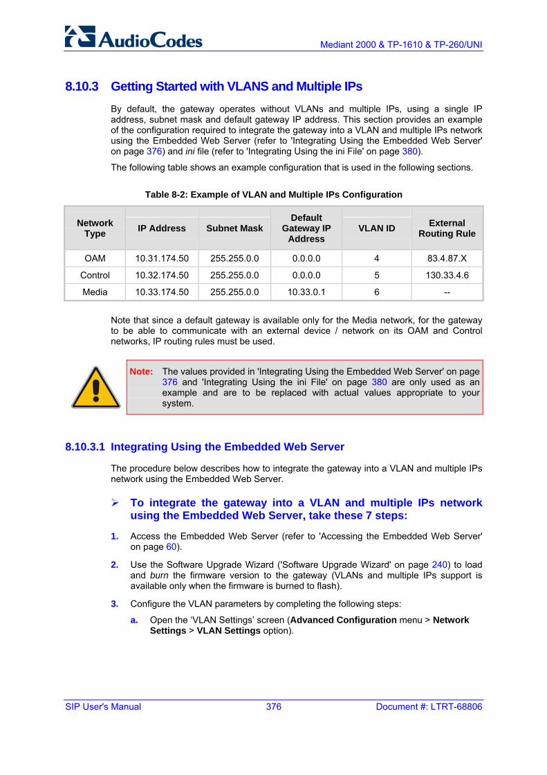
SIP User's Manual 376 Document #: LTRT-68806
Mediant 2000 & TP-1610 & TP-260/UNI
8.10.3 Getting Started with VLANS and Multiple IPs By default, the gateway operates without VLANs and multiple IPs, using a single IP address, subnet mask and default gateway IP address. This section provides an example of the configuration required to integrate the gateway into a VLAN and multiple IPs network using the Embedded Web Server (refer to 'Integrating Using the Embedded Web Server' on page 376) and ini file (refer to 'Integrating Using the ini File' on page 380).
The following table shows an example configuration that is used in the following sections.
Table 8-2: Example of VLAN and Multiple IPs Configuration
Network Type IP Address Subnet Mask
Default Gateway IP
Address VLAN ID External
Routing Rule
OAM 10.31.174.50 255.255.0.0 0.0.0.0 4 83.4.87.X
Control 10.32.174.50 255.255.0.0 0.0.0.0 5 130.33.4.6
Media 10.33.174.50 255.255.0.0 10.33.0.1 6 --
Note that since a default gateway is available only for the Media network, for the gateway to be able to communicate with an external device / network on its OAM and Control networks, IP routing rules must be used.
Note: The values provided in 'Integrating Using the Embedded Web Server' on page 376 and 'Integrating Using the ini File' on page 380 are only used as an example and are to be replaced with actual values appropriate to your system.
8.10.3.1 Integrating Using the Embedded Web Server
The procedure below describes how to integrate the gateway into a VLAN and multiple IPs network using the Embedded Web Server.
To integrate the gateway into a VLAN and multiple IPs network using the Embedded Web Server, take these 7 steps:
1. Access the Embedded Web Server (refer to 'Accessing the Embedded Web Server' on page 60).
2. Use the Software Upgrade Wizard ('Software Upgrade Wizard' on page 240) to load and burn the firmware version to the gateway (VLANs and multiple IPs support is available only when the firmware is burned to flash).
3. Configure the VLAN parameters by completing the following steps:
a. Open the ‘VLAN Settings’ screen (Advanced Configuration menu > Network Settings > VLAN Settings option).

Version 5.2 377 September 2007
SIP User's Manual 8. Networking Capabilities
b. Modify the VLAN parameters to correspond to the values shown in the following figure.
Figure 8-1: VLAN Settings Screen - Example
c. Click the Submit button to save your changes.
4. Configure the multiple IP parameters by completing the following steps:
a. Open the ‘IP Settings’ screen (Advanced Configuration menu > Network Settings > IP Settings option).
b. Modify the IP parameters to correspond to the values shown in the figure below. Note that the OAM, Control, and Media Network Settings parameters appear only after you select the options ‘Multiple IP Networks’ or 'Dual IP' in the field ‘IP Networking Mode’.
Note: Configure the OAM parameters only if the OAM networking parameters are different from the networking parameters used in the Single IP Network mode.

SIP User's Manual 378 Document #: LTRT-68806
Mediant 2000 & TP-1610 & TP-260/UNI
Figure 8-2: IP Settings Screen - Example
c. Click the Submit button to save your changes.
5. Configure the IP Routing table by completing the following steps (the IP Routing table is required to define static routing rules for the OAM and Control networks since a default gateway isn’t supported for these networks):
a. Open the ‘IP Routing Table’ screen (Advanced Configuration menu > Network Settings > IP Routing Table option).
Figure 8-3: IP Routing Table - Example

Version 5.2 379 September 2007
SIP User's Manual 8. Networking Capabilities
b. Use the ‘Add a new table entry’ pane to add the routing rules shown in the following table:
Destination IP Address Destination Mask Gateway IP
Address Hop Count Network Type
130.33.4.6 255.255.255.255 10.32.0.1 20 Control
83.4.87.6 255.255.255.0 10.31.0.1 20 OAM
a. Click the Submit button to save your changes.
6. Save your changes to flash memory (refer to 'Saving Configuration' on page 256).
7. Reset the gateway (refer to 'Resetting the Gateway' on page 257).

SIP User's Manual 380 Document #: LTRT-68806
Mediant 2000 & TP-1610 & TP-260/UNI
8.10.3.2 Integrating Using the ini File
The procedure below describes how to integrate the gateway into a VLAN and multiple IPs network using the ini file.
To integrate the gateway into a VLAN and multiple IPs network using the ini file, take these 3 steps:
1. Prepare an ini file with relevant parameters. Refer to the following notes:
• If the BootP/TFTP utility and the OAM interface are located in the same network, the Native VLAN ID (VlanNativeVlanId) must be equal to the OAM VLAN ID (VlanOamVlanId), which in turn must be equal to the PVID of the switch port to which the gateway is connected. Therefore, set the PVID of the switch port to 4 (in this example).
• Configure the OAM parameters (LocalOAMPAddress, LocalOAMSubnetMask and LocalOAMDefaultGW) only if the OAM networking parameters are different from the networking parameters used in the Single IP Network mode.
• The IP Routing table is required to define static routing rules for the OAM and Control networks since a default gateway isn’t supported for these networks.
Below is an example of an ini file containing VLAN and Multiple IPs parameters:
; VLAN Configuration VlanMode=1 VlanOamVlanId=4 VlanNativeVlanId=4 VlanControlVlanId=5 VlanMediaVlanID=6 ; Multiple IPs Configuration EnableMultipleIPs=1 LocalMediaIPAddress=10.33.174.50 LocalMediaSubnetMask=255.255.0.0 LocalMediaDefaultGW=10.33.0.1 LocalControlIPAddress=10.32.174.50 LocalControlSubnetMask=255.255.0.0 LocalControlDefaultGW=0.0.0.0 LocalOAMPAddress=10.31.174.50 LocalOAMSubnetMask=255.255.0.0 LocalOAMDefaultGW=0.0.0.0 ; IP Routing table parameters RoutingTableDestinationsColumn = 130.33.4.6, 83.4.87.6 RoutingTableDestinationMasksColumn = 255.255.255.255 , 255.255.255.0 RoutingTableGatewaysColumn = 10.32.0.1 , 10.31.0.1 RoutingTableInterfacesColumn = 1 , 0 RoutingTableHopsCountColumn = 20,20
2. Use the BootP/TFTP utility (refer to the SIP Series Reference Manual) to load and
burn (-fb option) the firmware version and the ini file you prepared in the previous step to the gateway (VLANs and multiple IPs support is available only when the firmware is burned to flash).
3. Reset the gateway after disabling it on the BootP/TFTP utility.

Version 5.2 381 September 2007
SIP User's Manual 9. Advanced PSTN Configuration
9 Advanced PSTN Configuration
9.1 Clock Settings The gateway Clock Settings can be configured to generate its own timing signals, use an internal clock, or recover them from one of the E1/T1 trunks.
To use the internal gateway clock source, configure the following parameters:
TDMBusClockSource = 1
ClockMaster = 1 (for all gateway trunks)
To use the recovered clock option configure the following parameters:
TDMBusClockSource = 4
ClockMaster_x = 0 (for all ‘slave’ gateway trunks connected to PBX#1)
ClockMaster_x = 1 (for all ‘master’ gateway trunks connected to PBX#2)
The above assumes that the gateway recovers its internal clock from one of the ‘slave’ trunks connected to PBX#1 and provides clock to PBX#2 on its ‘master’ trunks.
In addition, it's necessary to define from which of the ‘slave’ trunks the gateway recovers its clock:
TDMBusPSTNAutoClockEnable = 1 (The gateway automatically selects one of the connected ‘slave’ trunks) - Or -
TDMBusLocalReference = # (Trunk index: 0 to 7, default = 0)
Notes:
• To configure the TDM Bus Clock Source parameters using the Embedded Web Server, refer to 'Configuring the TDM Bus Settings' on page 195.
• When the gateway is used in a ‘non-span’ configuration, the internal gateway clock must be used (as explained above).

SIP User's Manual 382 Document #: LTRT-68806
Mediant 2000 & TP-1610 & TP-260/UNI
9.2 Release Reason Mapping This appendix describes the available mapping mechanisms of SIP Responses to Q.850 Release Causes and vice versa.
The existing mapping of ISDN Release Causes to SIP Responses is described in' Fixed Mapping of ISDN Release Reason to SIP Response' on page 383 and 'Fixed Mapping of SIP Response to ISDN Release Reason' on page 385. To override this hard-coded mapping and flexibly map SIP Responses to ISDN Release Causes, use the ini file (CauseMapISDN2SIP and CauseMapSIP2ISDN, as' described in ISDN and CAS Interworking-Related' on page 311 Parameters) or the Embedded Web Server (refer to 'Release Cause Mapping' on page 132).
It is also possible to map the less commonly-used SIP Responses to a single default ISDN Release Cause. Use the parameter DefaultCauseMapISDN2IP (described in 'ISDN and CAS Interworking-Related Parameters' on page 311) to define a default ISDN Cause that is always used except when the following Release Causes are received: Normal Call Clearing (16), User Busy (17), No User Responding (18) or No Answer from User (19). This mechanism is only available for Tel-to-IP calls.
9.2.1 Reason Header The gateway supports the Reason header according to RFC 3326. The Reason header is used to convey information describing the disconnection cause of a call:
Sending Reason header: If a call is disconnected from the Tel side (ISDN), the Reason header is set to the received Q.850 cause in the appropriate message (BYE / CANCEL / final failure response) and sent to the SIP side. If the call is disconnected because of a SIP reason, the Reason header is set to the appropriate SIP response.
Receiving Reason header: If a call is disconnected from the IP side and the SIP message includes the Reason header, it is sent to the Tel side according to the following logic:
• If the Reason header includes a Q.850 cause, it is sent as is.
• If the Reason header includes a SIP response:
♦ If the message is a final response, the response status code is translated to Q.850 format and passed to ISDN.
♦ If the message isn’t a final response, it is translated to a Q.850 cause.
• When the Reason header is received twice (i.e., SIP Reason and Q.850), the Q.850 takes precedence over the SIP reason and is sent to the Tel side.

Version 5.2 383 September 2007
SIP User's Manual 9. Advanced PSTN Configuration
9.2.2 Fixed Mapping of ISDN Release Reason to SIP Response The following table describes the mapping of ISDN release reason to SIP response.
Table 9-1: Mapping of ISDN Release Reason to SIP Response
ISDN Release Reason Description SIP
Response Description
1 Unallocated number 404 Not found
2 No route to network 404 Not found
3 No route to destination 404 Not found
6 Channel unacceptable 406* Not acceptable
7 Call awarded and being delivered in an established channel 500 Server internal error
16 Normal call clearing -* BYE
17 User busy 486 Busy here
18 No user responding 408 Request timeout
19 No answer from the user 480 Temporarily unavailable
21 Call rejected 403 Forbidden
22 Number changed w/o diagnostic 410 Gone
26 Non-selected user clearing 404 Not found
27 Destination out of order 502 Bad gateway
28 Address incomplete 484 Address incomplete
29 Facility rejected 501 Not implemented
30 Response to status enquiry 501* Not implemented
31 Normal unspecified 480 Temporarily unavailable
34 No circuit available 503 Service unavailable
38 Network out of order 503 Service unavailable
41 Temporary failure 503 Service unavailable
42 Switching equipment congestion 503 Service unavailable
43 Access information discarded 502* Bad gateway
44 Requested channel not available 503* Service unavailable
47 Resource unavailable 503 Service unavailable
49 QoS unavailable 503* Service unavailable
50 Facility not subscribed 503* Service unavailable
55 Incoming calls barred within CUG 403 Forbidden
57 Bearer capability not authorized 403 Forbidden
58 Bearer capability not presently available 503 Service unavailable

SIP User's Manual 384 Document #: LTRT-68806
Mediant 2000 & TP-1610 & TP-260/UNI
ISDN Release Reason Description SIP
Response Description
63 Service/option not available 503* Service unavailable
65 Bearer capability not implemented 501 Not implemented
66 Channel type not implemented 480* Temporarily unavailable
69 Requested facility not implemented 503* Service unavailable
70 Only restricted digital information bearer capability is available 503* Service unavailable
79 Service or option not implemented 501 Not implemented
81 Invalid call reference value 502* Bad gateway
82 Identified channel does not exist 502* Bad gateway
83 Suspended call exists, but this call identity does not 503* Service unavailable
84 Call identity in use 503* Service unavailable
85 No call suspended 503* Service unavailable
86 Call having the requested call identity has been cleared 408* Request timeout
87 User not member of CUG 503 Service unavailable
88 Incompatible destination 503 Service unavailable
91 Invalid transit network selection 502* Bad gateway
95 Invalid message 503 Service unavailable
96 Mandatory information element is missing 409* Conflict
97 Message type non-existent or not implemented 480* Temporarily not available
98 Message not compatible with call state or message type non-existent or not implemented
409* Conflict
99 Information element non-existent or not implemented 480* Not found
100 Invalid information elements contents 501* Not implemented
101 Message not compatible with call state 503* Service unavailable
102 Recovery of timer expiry 408 Request timeout
111 Protocol error 500 Server internal error
127 Interworking unspecified 500 Server internal error
* Messages and responses were created as the ‘ISUP to SIP Mapping’ draft doesn’t specify their cause code mapping.

Version 5.2 385 September 2007
SIP User's Manual 9. Advanced PSTN Configuration
9.2.3 Fixed Mapping of SIP Response to ISDN Release Reason The following table describes the mapping of SIP response to ISDN release reason.
Table 9-2: Mapping of SIP Response to ISDN Release Reason
SIP Response Description ISDN Release Reason Description
400* Bad request 31 Normal, unspecified
401 Unauthorized 21 Call rejected
402 Payment required 21 Call rejected
403 Forbidden 21 Call rejected
404 Not found 1 Unallocated number
405 Method not allowed 63 Service/option unavailable
406 Not acceptable 79 Service/option not implemented
407 Proxy authentication required 21 Call rejected
408 Request timeout 102 Recovery on timer expiry
409 Conflict 41 Temporary failure
410 Gone 22 Number changed w/o diagnostic
411 Length required 127 Interworking
413 Request entity too long 127 Interworking
414 Request URI too long 127 Interworking
415 Unsupported media type 79 Service/option not implemented
420 Bad extension 127 Interworking
480 Temporarily unavailable 18 No user responding
481* Call leg/transaction doesn’t exist 127 Interworking
482* Loop detected 127 Interworking
483 Too many hops 127 Interworking
484 Address incomplete 28 Invalid number format
485 Ambiguous 1 Unallocated number
486 Busy here 17 User busy
488 Not acceptable here 31 Normal, unspecified
500 Server internal error 41 Temporary failure
501 Not implemented 38 Network out of order
502 Bad gateway 38 Network out of order
503 Service unavailable 41 Temporary failure
504 Server timeout 102 Recovery on timer expiry

SIP User's Manual 386 Document #: LTRT-68806
Mediant 2000 & TP-1610 & TP-260/UNI
Table 9-2: Mapping of SIP Response to ISDN Release Reason
SIP Response Description ISDN Release Reason Description
505* Version not supported 127 Interworking
600 Busy everywhere 17 User busy
603 Decline 21 Call rejected
604 Does not exist anywhere 1 Unallocated number
606* Not acceptable 38 Network out of order
* Messages and responses were created as the ‘ISUP to SIP Mapping’ draft doesn’t specify their cause code mapping.
9.3 ISDN Overlap Dialing Overlap dialing is a dialing scheme used by several ISDN variants to send and / or receive called number digits one after the other (or several at a time). This is as opposed to en-bloc dialing in which a complete number is sent.
The gateway can optionally support ISDN overlap dialing for incoming ISDN calls for the entire gateway by setting the ini file parameter ISDNRxOverlap to 1, or per E1/T1 span by setting ISDNRxOverlap_x to 1 (where x represents the number of the trunk -- 0 to 7). For configuring ISDN overlap dialing using the Embedded Web Server, refer to 'Trunk Settings' on page 178.
To play a Dial tone to the ISDN user side when an empty called number is received, set ISDNINCallsBehavior = 65536 (bit #16). This results in the Progress Indicator to be included in the SetupAck ISDN message.
The gateway stops collecting digits (for ISDN-to-IP calls) when:
The sending device transmits a ‘sending complete’ IE in the ISDN Setup or the following INFO messages to signal that no more digits are going to be sent.
The inter-digit timeout (configured by the parameter TimeBetweenDigits) expires. The default for this timeout is 4 seconds.
The maximum allowed number of digits (configured by the parameter MaxDigits) is reached. The default is 30 digits.
A match is found with the defined digit map (configured by the parameter, DigitMapping).
Relevant parameters (described in 'PSTN Parameters' on page 307):
ISDNRxOverlap
ISDNRxOverlap_x
TimeBetweenDigits
MaxDigits
ISDNInCallsBehavior
DigitMapping

Version 5.2 387 September 2007
SIP User's Manual 9. Advanced PSTN Configuration
9.4 Using ISDN NFAS In regular (non-NFAS) T1 ISDN trunks, a single 64 kbps channel carries signaling for the other 23 B-channels of that particular T1 trunk. This channel is called the D-channel and usually resides on timeslot # 24.
The ISDN Non-Facility Associated Signaling (NFAS) feature enables use of a single D-channel to control multiple PRI interfaces.
With NFAS it is possible to define a group of T1 trunks, called an NFAS group, in which a single D-channel carries ISDN signaling messages for the entire group. The NFAS group’s B-channels are used to carry traffic, such as voice or data. The NFAS mechanism also enables definition of a backup D-channel on a different T1 trunk, to be used if the primary D-channel fails.
The NFAS group comprises several T1 trunks. Each T1 trunk is called an ‘NFAS member’. The T1 trunk whose D-channel is used for signaling is called the ‘Primary NFAS Trunk’. The T1 trunk whose D-channel is used for backup signaling is called the ‘Backup NFAS Trunk’. The primary and backup trunks each carry 23 B-channels while all other NFAS trunks each carry 24 B-channels.
The gateway supports multiple NFAS groups. Each group should contain different T1 trunks.
The NFAS group is identified by an NFAS GroupID number (possible values are 1, 2, 3 and 4). To assign a number of T1 trunks to the same NFAS group, use the ini file parameter NFASGroupNumber_x = groupID (where x is the physical trunkID -- 0 to 7) or the Embedded Web Server (refer to 'Trunk Settings' on page 178).
The parameter ‘DchConfig_x = Trunk_type’ is used to define the type of NFAS trunk. Trunk_type is set to 0 for the primary trunk, to 1 for the backup trunk, and to 2 for an ordinary NFAS trunk. ‘x’ depicts the physical trunkID (0 to 7). You can also use the Embedded Web Server (refer to 'Trunk Settings' on page 178).
For example, to assign the first four gateway T1 trunks to NFAS group #1, in which trunk #0 is the primary trunk and trunk #1 is the backup trunk, use the following configuration:
NFASGroupNumber_0 = 1 NFASGroupNumber_1 = 1 NFASGroupNumber_2 = 1 NFASGroupNumber_3 = 1 DchConfig_0 = 0 ;Primary T1 trunk DchConfig_1 = 1 ;Backup T1 trunk DchConfig_2 = 2 ;24 B-channel NFAS trunk DchConfig_3 = 2 ;24 B-channel NFAS trunk
The NFAS parameters are described in 'PSTN Parameters' on page 307.
9.4.1 NFAS Interface ID Several ISDN switches require an additional configuration parameter per T1 trunk that is called ‘Interface Identifier’. In NFAS T1 trunks, the Interface Identifier is sent explicitly in Q.931 Setup / Channel Identification IE for all NFAS trunks, except for the B-channels of the Primary trunk (refer to note below).
The Interface ID can be defined per each member (T1 trunk) of the NFAS group, and must be coordinated with the configuration of the Switch. The default value of the Interface ID is identical to the number of the physical T1 trunk (0 for the first gateway trunk, 1 for the second gateway T1 trunk, and so on, up to 7).

SIP User's Manual 388 Document #: LTRT-68806
Mediant 2000 & TP-1610 & TP-260/UNI
To define an explicit Interface ID for a T1 trunk (that is different from the default), use the following parameters:
ISDNIBehavior_x = 512 (x = 0 to 7 identifying the gateway physical trunk)
ISDNNFASInterfaceID_x = ID (x = 0 to 255)
Notes:
• Usually the Interface Identifier is included in the Q.931 Setup/Channel Identification IE only on T1 trunks that doesn’t contain the D-channel. Calls initiated on B-channels of the Primary T1 trunk, by default, don’t contain the Interface Identifier. Setting the parameter ISDNIBehavior_x to 2048’ forces the inclusion of the Channel Identifier parameter also for the Primary trunk.
• The parameter ISDNNFASInterfaceID_x = ID can define the ‘Interface ID’ for any Primary T1 trunk, even if the T1 trunk is not a part of an NFAS group. However, to include the Interface Identifier in Q.931 Setup/Channel Identification IE configure ISDNIBehavior_x = 2048 in the ini file.
9.4.2 Working with DMS-100 Switches The DMS-100 switch requires the following NFAS Interface ID definitions:
InterfaceID #0 for the Primary trunk
InterfaceID #1 for the Backup trunk
InterfaceID #2 for a 24 B-channel T1 trunk
InterfaceID #3 for a 24 B-channel T1 trunk
Etc.
For example, if four T1 trunks on a gateway are configured as a single NFAS group with Primary and Backup T1 trunks that is used with a DMS-100 switch, the following parameters should be used:
NFASGroupNumber_0 = 1 NFASGroupNumber_1 = 1 NFASGroupNumber_2 = 1 NFASGroupNumber_3 = 1 DchConfig_0 = 0 ;Primary T1 trunk DchConfig_1 = 1 ;Backup T1 trunk DchConfig_2 = 2 ;B-Channel NFAS trunk DchConfig_3 = 2 ;B-channel NFAS trunk

Version 5.2 389 September 2007
SIP User's Manual 9. Advanced PSTN Configuration
If there is no NFAS Backup trunk, the following configuration should be used:
ISDNNFASInterfaceID_0 = 0 ISDNNFASInterfaceID_1 = 2 ISDNNFASInterfaceID_2 = 3 ISDNNFASInterfaceID_3 = 4 ISDNIBehavior = 512 ;This parameter should be added because of ;ISDNNFASInterfaceID coniguration above NFASGroupNumber_0 = 1 NFASGroupNumber_1 = 1 NFASGroupNumber_2 = 1 NFASGroupNumber_3 = 1 DchConfig_0 = 0 ;Primary T1 trunk DchConfig_1 = 2 ;B-Channel NFAS trunk DchConfig_2 = 2 ;B-Channel NFAS trunk DchConfig_3 = 2 ;B-channel NFAS trunk
9.4.3 Creating an NFAS-Related Trunk Configuration On-The-Fly The procedures for creating and deleting an NFAS group on-the-fly must be performed in the correct order, as described below.
To create an NFAS Group, take these 3 steps:
1. If there’s a backup (‘secondary’) trunk for this group, it must be configured first.
2. Configure the primary trunk before configuring any NFAS (‘slave’) trunk.
3. Configure NFAS (‘slave’) trunks.
To stop / delete an NFAS Group, take these 3 steps:
1. Stop / delete all NFAS (‘slave’) trunks.
2. Stop / delete the backup trunk if a backup trunk exists.
3. Stop / delete the primary trunk.
Notes:
• All trunks in the group must be configured with the same values for trunk parameters TerminationSide, ProtocolType, FramingMethod, and LineCode.
• After stopping or deleting the backup trunk, delete the group and then reconfigure it.

SIP User's Manual 390 Document #: LTRT-68806
Mediant 2000 & TP-1610 & TP-260/UNI
9.5 Redirect Number and Calling Name (Display) The following tables define the gateway redirect number and calling name (Display) support for various PRI variants:
Table 9-3: Calling Name (Display)
DMS-100 NI-2 4/5ESS Euro ISDN
NT TE Yes Yes Yes Yes
TE NT Yes Yes Yes No
Table 9-4: Redirect Number
DMS-100 NI-2 4/5ESS Euro ISDN
NT TE Yes Yes Yes Yes
TE NT Yes Yes Yes No

Version 5.2 391 September 2007
SIP User's Manual 10. Tunneling Applications
10 Tunneling Applications
10.1 TDM Tunneling The gateway TDM Tunneling feature allows you to tunnel groups of digital trunk spans or timeslots (B-channels) over the IP network. TDM Tunneling utilizes the internal routing capabilities of the gateway (without Proxy control) to receive voice and data streams from TDM (1 to 16 E1/T1/J1) spans or individual timeslots, convert them into packets and transmit them automatically over the IP network (using point-to-point or point-to-multipoint gateway distributions). A gateway opposite it (or several gateways when point-to-multipoint distribution is used) converts the IP packets back into TDM traffic. Each timeslot can be targeted to any other timeslot within a trunk in the opposite gateway.
10.1.1 Implementation When TDM Tunneling is enabled (EnableTDMOverIP is set to 1 on the originating gateway), the originating gateway automatically initiates SIP calls from all enabled B-channels belonging to the E1/T1/J1 spans that are configured with the ‘Transparent’ protocol (for ISDN trunks), or ‘Raw CAS’ (for CAS trunks). The called number of each call is the internal phone number of the B-channel that the call originates from. The IP to Trunk Group routing table is used to define the destination IP address of the terminating gateway. The terminating gateway automatically answers these calls if its E1/T1 protocol is set to ‘Transparent’ (ProtocolType = 5), or ‘Raw CAS’ (ProtocolType = 3 for T1 and 9 for E1) and the parameter ChannelSelectMode is set to 0 (By Phone Number).
Note: It's possible to configure both gateways to also operate in symmetric mode. To do so, set EnableTDMOverIP to 1 and configure the Tel to IP Routing tables in both gateways. In this mode, each gateway (after it's reset) initiates calls to the second gateway. The first call for each B-channel is answered by the second gateway.
The gateway monitors the established connections continuously, if for some reason one or more calls are released, the gateway automatically reestablishes these ‘broken’ connections. In addition, when a failure in a physical trunk or in the IP network occurs, the gateways reestablish the tunneling connections as soon as the network restores.
Note: It's recommended to use the keep-alive mechanism for each connection by activating ‘session expires’ timeout, and using ReINVITE messages.
By utilizing the ‘Profiles’ mechanism (refer to 'Configuring the Profile Definitions' on page 132) you can configure the TDM Tunneling feature to choose different settings, based on a timeslot or groups of timeslots. For example, you can use low-bit-rate vocoders to transport voice, and ‘Transparent’ coder to transport data (e.g., for D-channel). You can also use Profiles to assign ToS (for DiffServ) per source, a time-slot carrying data or signaling gets a higher priority value than a time-slot carrying voice.
For tunneling of E1/T1 CAS trunks set the protocol type to Raw CAS (ProtocolType = 3 / 9) and enable RFC 2833 CAS relay mode (CASTransportType = 1).

SIP User's Manual 392 Document #: LTRT-68806
Mediant 2000 & TP-1610 & TP-260/UNI
Note: For TDM over IP, the CallerIDTransportType parameter must be set to 0 (transparent).
Below is an example of ini files for two gateways implementing TDM Tunneling for four E1 spans. Note that in this example both gateways are dedicated to TDM tunneling.
Terminating Side: EnableTDMOverIP = 1 ;E1_TRANSPARENT_31 ProtocolType_0 = 5 ProtocolType_1 = 5 ProtocolType_2 = 5 ProtocolType_3 = 5 [PREFIX] FORMAT PREFIX_Index = PREFIX_DestinationPrefix, PREFIX_DestAddress, PREFIX_SourcePrefix, PREFIX_ProfileId, PREFIX_MeteringCode, PREFIX_DestPort; Prefix 1 = '*,10.8.24.12'; [\PREFIX] ; IP address of the gateway in the opposite ; location ; Channel selection by Phone number. ChannelSelectMode = 0 ;Profiles can be used do define different coders per B-channels ;such as Transparent ; coder for B-channels (time slot 16) that carries PRI ;signaling.[TrunkGroup] FORMAT TrunkGroup_Index = TrunkGroup_TrunkGroupNum, TrunkGroup_FirstTrunkId, TrunkGroup_LastTrunkId, TrunkGroup_FirstBChannel, TrunkGroup_LastBChannel, TrunkGroup_FirstPhoneNumber, TrunkGroup_ProfileId, TrunkGroup_Module; TrunkGroup 1 = 0,0,0,1,31,1000,1; TrunkGroup 1 = 0,1,1,1,31,2000,1; TrunkGroup 1 = 0,2,2,1,31,3000,1; TrunkGroup 1 = 0,3,3,1,31,4000,1; TrunkGroup 1 = 0,0,0,16,16,7000,2; TrunkGroup 1 = 0,1,1,16,16,7001,2; TrunkGroup 1 = 0,2,2,16,16,7002,2; TrunkGroup 1 = 0,3,3,16,16,7003,2; [/TrunkGroup] [CoderName] FORMAT CoderName_Index = CoderName_Type, CoderName_PacketInterval, CoderName_rate, CoderName_PayloadType, CoderName_Sce; CoderName 0 = 'g7231'; CoderName 1 = 'Transparent'; CoderName 5 = 'g7231'; CoderName 6 = 'Transparent'; [/CoderName] [TelProfile] FORMAT TelProfile_Index = TelProfile_ProfileName, TelProfile_TelPreference, TelProfile_CodersGroupID, TelProfile_IsFaxUsed, TelProfile_JitterBufMinDelay, TelProfile_JitterBufOptFactor, TelProfile_IPDiffServ, TelProfile_SigIPDiffServ, TelProfile_DtmfVolume, TelProfile_InputGain, TelProfile_VoiceVolume, TelProfile_EnableReversePolarity, TelProfile_EnableCurrentDisconnect, TelProfile_EnableDigitDelivery, TelProfile_EnableEC, TelProfile_MWIAnalog, TelProfile_MWIDisplay,
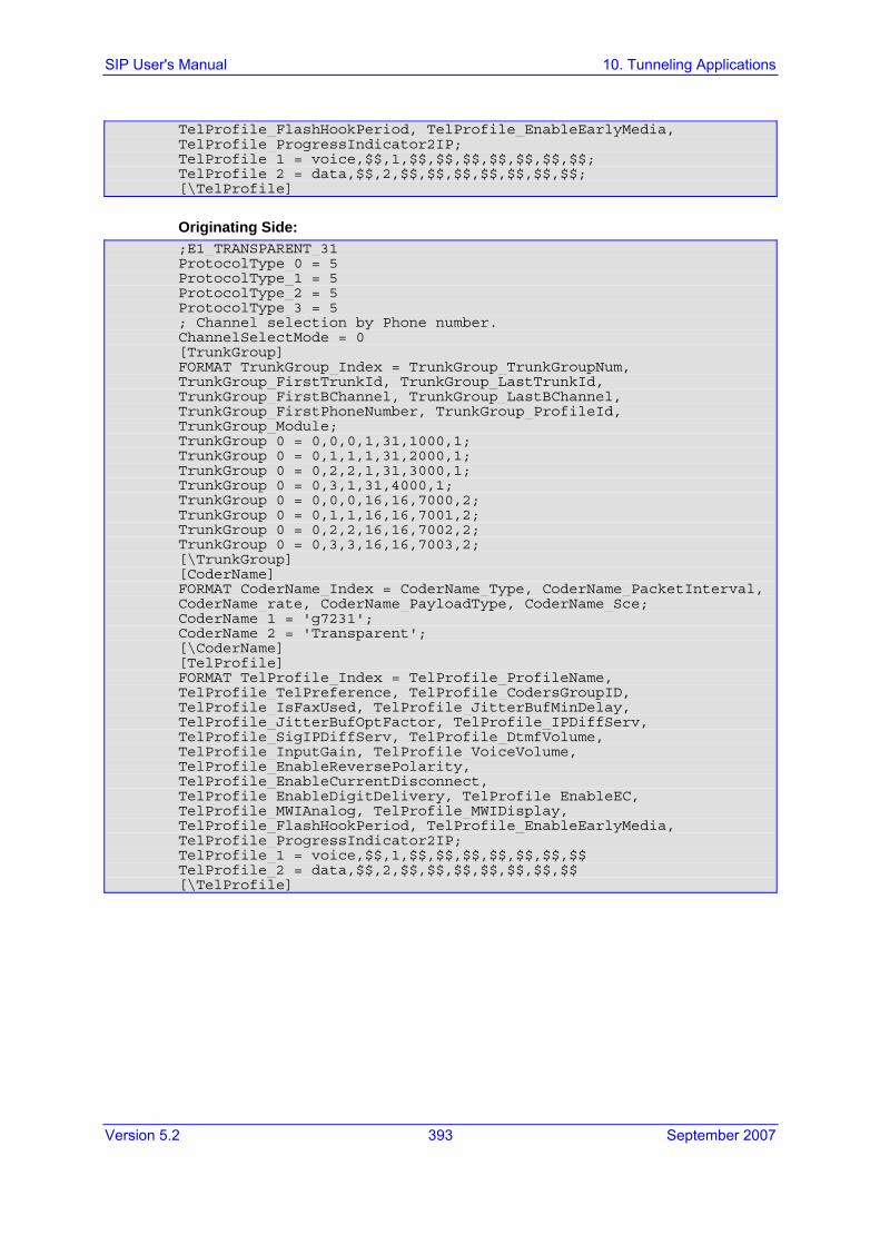
Version 5.2 393 September 2007
SIP User's Manual 10. Tunneling Applications
TelProfile_FlashHookPeriod, TelProfile_EnableEarlyMedia, TelProfile_ProgressIndicator2IP; TelProfile 1 = voice,$$,1,$$,$$,$$,$$,$$,$$,$$; TelProfile 2 = data,$$,2,$$,$$,$$,$$,$$,$$,$$; [\TelProfile]
Originating Side: ;E1_TRANSPARENT_31 ProtocolType_0 = 5 ProtocolType_1 = 5 ProtocolType_2 = 5 ProtocolType_3 = 5 ; Channel selection by Phone number. ChannelSelectMode = 0 [TrunkGroup] FORMAT TrunkGroup_Index = TrunkGroup_TrunkGroupNum, TrunkGroup_FirstTrunkId, TrunkGroup_LastTrunkId, TrunkGroup_FirstBChannel, TrunkGroup_LastBChannel, TrunkGroup_FirstPhoneNumber, TrunkGroup_ProfileId, TrunkGroup_Module; TrunkGroup 0 = 0,0,0,1,31,1000,1; TrunkGroup 0 = 0,1,1,1,31,2000,1; TrunkGroup 0 = 0,2,2,1,31,3000,1; TrunkGroup 0 = 0,3,1,31,4000,1; TrunkGroup 0 = 0,0,0,16,16,7000,2; TrunkGroup 0 = 0,1,1,16,16,7001,2; TrunkGroup 0 = 0,2,2,16,16,7002,2; TrunkGroup 0 = 0,3,3,16,16,7003,2; [\TrunkGroup] [CoderName] FORMAT CoderName_Index = CoderName_Type, CoderName_PacketInterval, CoderName_rate, CoderName_PayloadType, CoderName_Sce; CoderName 1 = 'g7231'; CoderName 2 = 'Transparent'; [\CoderName] [TelProfile] FORMAT TelProfile_Index = TelProfile_ProfileName, TelProfile_TelPreference, TelProfile_CodersGroupID, TelProfile_IsFaxUsed, TelProfile_JitterBufMinDelay, TelProfile_JitterBufOptFactor, TelProfile_IPDiffServ, TelProfile_SigIPDiffServ, TelProfile_DtmfVolume, TelProfile_InputGain, TelProfile_VoiceVolume, TelProfile_EnableReversePolarity, TelProfile_EnableCurrentDisconnect, TelProfile_EnableDigitDelivery, TelProfile_EnableEC, TelProfile_MWIAnalog, TelProfile_MWIDisplay, TelProfile_FlashHookPeriod, TelProfile_EnableEarlyMedia, TelProfile_ProgressIndicator2IP; TelProfile_1 = voice,$$,1,$$,$$,$$,$$,$$,$$,$$ TelProfile_2 = data,$$,2,$$,$$,$$,$$,$$,$$,$$ [\TelProfile]

SIP User's Manual 394 Document #: LTRT-68806
Mediant 2000 & TP-1610 & TP-260/UNI
10.2 QSIG Tunneling The gateway supports QSIG tunneling over SIP according to <draft-elwell-sipping-qsig-tunnel-03>. This method enables all QSIG messages to be sent as raw data in corresponding SIP messages using a dedicated message body. This mechanism is useful for two QSIG subscribers (connected to the same / different QSIG PBX) to communicate with each other over an IP network. Tunneling is supported for both directions (Tel to IP and IP to Tel).
The term tunneling means that messages are transferred ‘as is’ to the remote side, without being converted (QSIG SIP QSIG). The advantage of tunneling over QSIG SIP interworking is that by using interworking, QSIG functionality can only be partially achieved. When tunneling is used, all QSIG capabilities are supported, whereas the tunneling medium (the SIP network) does not need to process these messages.
10.2.1 Implementation QSIG messages are transferred in SIP messages in a separate Multipurpose Internet Mail Extensions (MIME) body. Therefore, if a message contains more than one body (e.g., SDP and QSIG), multipart MIME must be used. The Content-Type of the QSIG tunneled message is ‘application/QSIG’. In addition, the gateway adds a Content-Disposition header in the following format:
Content-Disposition: signal; handling=required.
Call setup (originating gateway):
The QSIG SETUP request is encapsulated in a SIP INVITE message without being altered. After the SIP INVITE request is sent, the gateway doesn’t encapsulate the following QSIG message until a SIP 200 OK response is received. If the originating gateway receives a 4xx, 5xx or 6xx response, it disconnects the QSIG call with a ‘no route to destination’ cause.
Call setup (terminating gateway): After the terminating gateway receives a SIP INVITE request with a Content-Type: application/QSIG, it sends the encapsulated QSIG SETUP message to the Tel side and sends a 200 OK response (no 1xx response is sent) to IP. The 200 OK response includes an encapsulated QSIG CALL PROCEEDING message (without waiting for a CALL PROCEEDING message from the Tel side). If tunneling is disabled and the incoming INVITE includes a QSIG body, a 415 response is sent.
Mid-call communication: After the SIP connection is established, all QSIG messages are encapsulated in SIP INFO messages.
Call tear-down: The SIP connection is terminated once the QSIG call is complete. The RELEASE COMPLETE message is encapsulated in the SIP BYE message that terminates the session.
To enable QSIG tunneling set the parameter EnableQSIGTunneling to 1 on both the originating and terminating gateways, and the parameter ISDNDuplicateQ931BuffMode to 128 (duplicate all messages) (both parameters are described in 'ISDN and CAS Interworking-Related Parameters' on page 311).

Version 5.2 395 September 2007
SIP User's Manual 11. Selected Technical Specifications
11 Selected Technical Specifications The General Specifications (listed in 'General Specifications' on page 395) apply to the Mediant 2000, TP-1610 and TP-260 gateways. For the product-specific specifications, refer to the following sections:
Mediant 2000 (refer to 'Mediant 2000 Specifications' on page 397)
TP-1610 (refer to 'TP-1610 Specifications' on page 399)
TP-260 (refer to 'TP-260 Specifications' on page 401)
Note: All specifications in this document are subject to change without prior notice.
11.1 General Specifications Table 11-1: General Selected Technical Specifications
Function Specification
Voice & Tone Characteristics
Voice Compression G.711 PCM at 64 kbps µ-law/A-law; G.723.1 MP-MLQ at 5.3 or 6.3 kbps; G.726 at 32 kbps ADPCM; G.729 CS-ACELP 8 kbps Annex A / B; NetCoder at 6.4, 7.2, 8.0 and 8.8 kbps; EVRC; AMR; Transparent; GSM Full Rate; Microsoft GSM; GSM-EFR; iLBC; QCELP
Silence Suppression G.723.1 Annex A G.729 Annex B PCM and ADPCM: Standard Silence Descriptor (SID) with Proprietary Voice Activity Detection (VAD) and Comfort Noise Generation (CNG) NetCoder
Packet Loss Concealment
G.711 appendix 1 G.723.1 G.729 a/b
Echo Cancellation G.165 and G.168 2000, configurable tail length per gateway from 32 to 128 msec
DTMF Detection and Generation
Dynamic range 0 to -25 dBm, compliant with TIA 464B and Bellcore TR-NWT-000506.
DTMF Transport (in-band)
Mute, transfer in RTP payload or relay in compliance with RFC 2833
Call Progress Tone Detection and Generation
32 tones: single tone, dual tones or AM tones, programmable frequency & amplitude; 64 frequencies in the range 300 to 1980 Hz, 1 to 4 cadences per tone, up to 4 sets of ON/OFF periods.
Output Gain Control -32 dB to +31 dB in steps of 1 dB
Input Gain Control -32 dB to +31 dB in steps of 1 dB

SIP User's Manual 396 Document #: LTRT-68806
Mediant 2000 & TP-1610 & TP-260/UNI
Table 11-1: General Selected Technical Specifications
Function Specification
Fax and Modem Transport Modes
Real time Fax Relay Group 3 real-time fax relay up to 14400 bps with auto fallback Tolerant network delay (up to 9 seconds round trip delay) T.30 (PSTN) and T.38 (IP) compliant (real-time fax) CNG tone detection & Relay per T.38 Answer tone (CED or AnsAm) detection & Relay per T.38
Fax Transparency Automatic fax bypass (pass-through) to G.711, ADPCM or NSE bypass mode
Modem Transparency Automatic switching (pass-through) to PCM, ADPCM or NSE bypass mode for modem signals (V.34 or V.90 modem detection)
Protocols
VoIP Signaling Protocol SIP RFC 3261
Communication Protocols
RTP/RTCP packetization. IP stack (UDP, TCP, RTP). Remote Software load (TFTP, HTTP and HTTPS).
Telephony Protocols PRI (ETSI Euro ISDN, ANSI NI2, 4/5ESS, DMS 100, QSIG, Japan INS1500, Australian Telecom, New Zealand Telecom, Hong Kong Variant, Korean MIC) E1/T1 CAS protocols: MFC R2, E&M wink start, Immediate start, delay start, loop start, ground start, Feature Group B, D for E1/T1
In-Band Signaling DTMF (TIA 464A) MF-R1, MFC R2 User-defined Call Progress Tones
Diagnostics
Front panel Status LEDs E1/T1 status LAN status Status of gateway (Fail, ACT, Power, and Swap Ready)
Syslog events Supported by Syslog Server, per RFC 3164 IETF standard.
SNMP MIBs and Traps SNMP v2c; SNMP v3
Management
Configuration Configuration of gateway using Web browser or ini files
SNMP v2c; SNMP v3
Syslog, per RFC 3164
Web Management (via HTTP or HTTPS)
Management and Maintenance
Telnet

Version 5.2 397 September 2007
SIP User's Manual 11. Selected Technical Specifications
11.2 Mediant 2000 Specifications Table 11-2: Mediant 2000 Selected Technical Specifications
Function Specification
Trunk & Channel Capacity
Capacity with E1
1, 2, 4, 8 or 16 E1 spans, 30, 60, 120, 240 or 480 digital channels: 30 Channels on 1 E1 span with gateway-1 only 60 Channels on 2 E1 spans with gateway-1 only 120 Channels on 4 E1 spans with gateway-1 only 240 Channels on 8 E1 spans with gateway-1 only 480 Channels on 16 E1 spans with gateway-1 and gateway-2 Note: Mediant 2000 channel capacity depends on configuration settings.
Interfaces
Telephony Interface 1, 2, 4, 8 or 16 E1/T1/J1 Balanced 120/100 ohm, or 75 ohm using a BNC to RJ-45 dual E1/T1 G.703 Balun adapter. Note: The following Balun adaptors were tested and certified by AudioCodes: Manufacture Name: AC&E (Part Number: B04040072) Manufacture Name: RIT (Part Number: R3712271)
Network Interface Two 10/100 Base-TX, half or full duplex with auto-negotiation
RS-232 Interface RS-232 Terminal Interface. DB-9 connector on rear panel (available only on the 1, 2 and 4-span configurations).
LED Indicators
LED Indications on Front Panel Power, ACT/Fail, T1/E1 status, LAN status, Swap ready indication
Connectors & Switches
Rear Panel
Trunks 1 to 8 and 9 to 16
Two 50-pin female Telco connectors (DDK57AE-40500-21D) or 8 RJ-48c connectors for trunks 1 to 8 only
Ethernet 1 and 2 Two 10/100 Base-TX, RJ-45 shielded connectors
RS-232 Console port: DB-9
AC Power Standard IEC320 Appliance inlet. Option for a dual (fully redundant) power supply.
DC Power 2-pin terminal block (screw connection type) suitable for field wiring applications connecting DC Power connector: MSTB2.5/2-STF (5.08 mm) from Phoenix Contact. Bonding and earthing: A 6-32-UNC screw is provided. Correct ring terminal and 16 AWG wire minimum must be used for connection. Or crimp connection shown below.
Note: To meet UL approval, users must fulfill the criteria below: 2-pin terminal block (crimp connection type) comprising a Phoenix Contact Adaptor: Shroud MSTBC2,5/2-STZF-5,08 Contacts: MSTBC-MT0,5-1,0 Cable requirement: 18 AWG x 1.5 m length

SIP User's Manual 398 Document #: LTRT-68806
Mediant 2000 & TP-1610 & TP-260/UNI
Table 11-2: Mediant 2000 Selected Technical Specifications
Function Specification
Physical
AC Power Supply Universal 90 to 260 VAC 1A max, 47-63 Hz Option for a dual redundant power supply.
AC Power Consumption 1 or 2 span: 39.7 W 4 spans: 42.1 W (approximated) 8 spans: 45.3 W
DC Power Supply (optional)
36 to 72 VDC (nominal 48 VDC), 4A max, floating input
DC Power Consumption 1 or 2 span: 28.8 W 4 spans: 32.8 W 8 spans: 36.4 W
Environmental (DC) Operation Temp: 0 to 40 °C (32 to 104 °F) Short Term Operation Temp (per NEBS): 0 to 55 °C (32 to 131 °F) Storage: -40 to 70 °C (-40 to 158 °F) Humidity: 10 to 90% non-condensing
Environmental (AC) Operation Temp: 0 to 40 °C (32 to 104 °F) Storage: -40 to 70 °C (-40 to 158 °F) Humidity: 10 to 90% non-condensing
Hot Swap cPCI cards are full hot swap supported Power supplies are redundant but not hot swappable
Enclosure Dimensions 445 x 44 x 300 mm (17.5 x 1.75 x 12 inches)
Weight Approx. 4.8 kg fully populated (16 spans); 4.2 kg for 1 span
Installation 1U 19-inch 2-slot cPCI chassis; rack-, shelf-, or desktop-mount options.Rack mount with 2 side brackets; optional -- 2 extra (rear) side brackets.
Type Approvals
Telecommunication Standards
IC CS03; FCC part 68 Chassis and Host telecom card are approved to the following telecom standards: IC CS03; FCC part 68; CTR 4, CTR 12 & CTR 13; JATE; Anatel, Mexico Telecom, Russia CCC, ASIF S016, ASIF S038.
Safety and EMC Standards
UL 60 950-1, FCC part 15 Class B, (Class A with SUN 2080 CPU card)CE Mark (EN 55022 Class B (Class A with SUN 2080 CPU card), EN 60950-1, EN 55024, EN 300 386), TS001
Environmental NEBS Level 3: GR-63-Core, GR-1089-Core, Type 1 & 3. Approved for DC powered version. Complies with ETS 301019; ETS 300019-1, -2, -3. (T 1.1, T 2.3, T3.2). Approved for AudioCodes or DC powered versions.
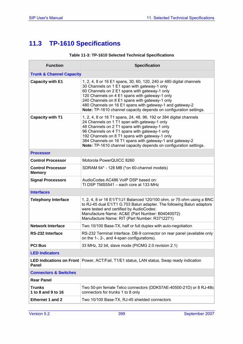
Version 5.2 399 September 2007
SIP User's Manual 11. Selected Technical Specifications
11.3 TP-1610 Specifications Table 11-3: TP-1610 Selected Technical Specifications
Function Specification
Trunk & Channel Capacity
Capacity with E1 1, 2, 4, 8 or 16 E1 spans, 30, 60, 120, 240 or 480 digital channels 30 Channels on 1 E1 span with gateway-1 only 60 Channels on 2 E1 spans with gateway-1 only 120 Channels on 4 E1 spans with gateway-1 only 240 Channels on 8 E1 spans with gateway-1 only 480 Channels on 16 E1 spans with gateway-1 and gateway-2 Note: TP-1610 channel capacity depends on configuration settings.
Capacity with T1 1, 2, 4, 8 or 16 T1 spans, 24, 48, 96, 192 or 384 digital channels 24 Channels on 1 T1 span with gateway-1 only 48 Channels on 2 T1 spans with gateway-1 only 96 Channels on 4 T1 spans with gateway-1 only 192 Channels on 8 T1 spans with gateway-1 only 384 Channels on 16 T1 spans with gateway-1 and gateway-2 Note: TP-1610 channel capacity depends on configuration settings.
Processor
Control Processor Motorola PowerQUICC 8260
Control Processor Memory
SDRAM 64* - 128 MB (*on 60-channel models)
Signal Processors AudioCodes AC486 VoIP DSP based on: TI DSP TMS5541 – each core at 133 MHz
Interfaces
Telephony Interface 1, 2, 4, 8 or 16 E1/T1/J1 Balanced 120/100 ohm, or 75 ohm using a BNC to RJ-45 dual E1/T1 G.703 Balun adapter. The following Balun adaptors were tested and certified by AudioCodes: Manufacture Name: AC&E (Part Number: B04040072) Manufacture Name: RIT (Part Number: R3712271)
Network Interface Two 10/100 Base-TX, half or full duplex with auto-negotiation
RS-232 Interface RS-232 Terminal Interface. DB-9 connector on rear panel (available only on the 1-, 2-, and 4-span configurations).
PCI Bus 33 MHz, 32 bit, slave mode (PICMG 2.0 revision 2.1)
LED Indicators
LED Indications on Front Panel
Power, ACT/Fail, T1/E1 status, LAN status, Swap ready indication
Connectors & Switches
Rear Panel
Trunks 1 to 8 and 9 to 16
Two 50-pin female Telco connectors (DDK57AE-40500-21D) or 8 RJ-48c connectors for trunks 1 to 8 only
Ethernet 1 and 2 Two 10/100 Base-TX, RJ-45 shielded connectors

SIP User's Manual 400 Document #: LTRT-68806
Mediant 2000 & TP-1610 & TP-260/UNI
Table 11-3: TP-1610 Selected Technical Specifications
Function Specification
RS-232 Console port - DB-9
Physical
Physical 6U single cPCI slot. PICMG 2.0, R2.1 and R2.16 and R.3.0 CompactPCI™ card
Supply Voltages and Power Consumption (typical)
480 channels: 40.7 W; 3 A at 5 V; 7.8 A at 3.3 V 240 channels: 24 W; 1.5 A at 5 V; 5 A at 3.3 V 120 channels: 18.4 W; 0.9 A at 5 V; 4.2 A at 3.3 V
Environmental Humidity: 10 to 90% non-condensing
Cooling 500 LFM at 50°C Ambient temp. supporting 480 ports, 400 Linear Feet per Minute (LFM) at 50°C ambient temp. supporting 400 ports 300 LFM at 50 °C ambient temp. supporting 240 ports
Hot Swap Full hot swap supported blades
Type Approvals
Telecommunication Standards
IC CS03, FCC part 68 CTR4, CTR12 , CTR13, JATE, TS.016, TSO, Anatel, Mexico Telecom
Safety and EMC Standards
UL 60950, FCC part 15 Class B, CE Mark (EN55022, EN60950, EN55024, EN300 386)

Version 5.2 401 September 2007
SIP User's Manual 11. Selected Technical Specifications
11.4 TP-260 Specifications
Table 11-4: TP-260 Selected Technical Specifications
Function Specification
Trunk & Channel Capacity
Capacity with E1 1, 2, 4 or 8 E1 spans, 30, 60, 120 or 240 digital channels Note: TP-260 channel capacity depends on configuration settings.
Capacity with T1 1, 2, 4 or 8 T1 spans, 24, 48, 96 or 192 digital channels Note: TP-260 channel capacity depends on configuration settings.
Interfaces
PCI Universal PCI 33/66 MHz, 32/64-bit, 3.3/5V signaling blade
Telephony Up to eight 120-ohm RJ-48C connectors (with adaptor)
Network Ethernet RJ-45 connector, 10/100 Base-TX
LED Indicators
LEDs T1/E1 status, LAN status
Physical
Form Factor Full length single slot PCI card
Supply Voltages and Power Consumption (typical)
8 trunks/240 channels - 18 W (3.6 A at 5V)
Environmental Humidity: 10 to 90% non-condensing
Cooling Requirement 500 LFM at 50 °C ambient temp. supporting 8 ports
Type Approvals
Safety and EMC Standards
UL 60950, FCC part 15 Class B, CE Mark (EN55022, EN60950, EN55024)

SIP User's Manual 402 Document #: LTRT-68806
Mediant 2000 & TP-1610 & TP-260/UNI
Reader's Notes

Version 5.2 403 September 2007
SIP User's Manual 12. Supplied SIP Software Package
12 Supplied SIP Software Package The table below lists the supplied standard SIP software package for the Mediant 2000, TP-1610, and TP-260 SIP gateways. (The supplied documentation includes this User's Manual and the Release Notes.)
Table 12-1: Supplied Software Package
File Name Description
Ram.cmp file
Mediant_SIP_xxx.cmp Image file containing the software for the Mediant 2000 and TP-1610 gateways.
TP260_UN_SIP_xxx.cmp Image file containing the software for the TP-260 gateway.
ini files
Mediant_SIP_T1.ini Sample ini file for Mediant 2000 / TP-1610 E1 gateways.
Mediant_SIP_E1.ini Sample ini file for Mediant 2000 / TP-1610 T1 gateways.
TP260_SIP_T1.ini Sample ini file for TP-260 E1 gateways.
TP260_SIP_E1.ini Sample ini file for TP-260 T1 gateways.
Usa_tones_xx.dat Default loadable Call Progress Tones dat file
Usa_tones_xx.ini Call Progress Tones ini file (used to create dat file)
voice_prompts.dat Sample loadable Voice Prompts dat file
Utilities
DConvert TrunkPack Downloadable Conversion Utility
ACSyslog Syslog server
BootP BootP/TFTP configuration utility
CAS Protocol Files Used for various signaling types, such as E_M_WinkTable.dat
MIB Files MIB library for SNMP browser
CAS Capture Tool Utility that is used to convert CAS traces to textual form
ISDN Capture Tool Utility that is used to convert ISDN traces to textual form
260_UNSeries.inf A PCI driver for the TP-260 that is used to prevent the Found new Hardware Wizard to reappear each time the host PC restarts.