ITS specification: Support sructures and foundations (ITS ... · 2) Document information ... The...
37
ITS specification Support structures and foundations (ITS-01-05) © NZ Transport Agency First edition, Amendment 0 Effective from September 2011
Transcript of ITS specification: Support sructures and foundations (ITS ... · 2) Document information ... The...

ITS specification Support structures and foundations (ITS-01-05)
© NZ Transport Agency
First edition, Amendment 0
Effective from September 2011

Copyright information
This publication is copyright © NZ Transport Agency (NZTA). Material in it may be reproduced for personal or in-house use without formal permission or charge, provided suitable acknowledgement is made to this publication and the NZTA as the source. Requests and enquiries about the reproduction of material in this publication for any other purpose should be made to:
NZ Transport Agency Private Bag 6995 Wellington 6141
The permission to reproduce material in this publication does not extend to any material for which the copyright is identified as being held by a third party. Authorisation to reproduce material belonging to a third party must be obtained from the copyright holder(s) concerned.
Disclaimer
The NZTA has endeavoured to ensure material in this document is technically accurate and reflects legal requirements. However, the document does not override governing legislation. The NZTA does not accept liability for any consequences arising from the use of this document. If the user of this document is unsure whether the material is correct, they should refer directly to the relevant legislation and contact the NZTA.
More information …
Published September 2011
If you have further queries, call our contact centre on 0800 699 000 or write to us:
NZ Transport Agency Private Bag 6995 Wellington 6141
This document is available on the NZTA’s website at www.nzta.govt.nz.

Page i
NZ Transport Agency’s ITS specification: Support structures and foundations (ITS-01-05) First edition, Amendment 0
Document management plan
1) Purpose
The purpose of this document is to specify the requirements for support structures and associated foundations for ITS equipment and systems design and installation.
2) Document information
Document name ITS specification: Support structures and foundations
Document number ITS-01-05
Document status Final
Document availability This document is located in electronic form on the NZ Transport Agency’s website at www.nzta.govt.nz.
Document author Waterview ITS Requirements Working Group: Jamie French [email protected]
(09) 300 9340
Tom Harris [email protected]
(09) 355 9542
Document owner Henry Pretorius
3) Key words
ITS Support Structures and Foundations Requirements

Page ii
NZ Transport Agency’s ITS specification: Support structures and foundations (ITS-01-05) First edition, Amendment 0
Record of amendments
Amendment number
Section amended
Description of change Updated by Effective date
0 All ITS Draft Specifications Issue TLH 20/9/2010
Draft R1 All AMA Specifications Review JF & TLH 25/1/2011

Page iii
NZ Transport Agency’s ITS specification: Support structures and foundations (ITS-01-05) First edition, Amendment 0
Contents
Document management plan i
Record of amendments ii
1.0 General 1
1.1 Scope 1
1.2 Standard drawings 1
2.0 Design criteria 2
2.1 General 2
2.2 Design standards 2
2.3 Site location and layout 2
2.4 Stage 3 safety audit 3
2.5 Roadside cabinet plinths and aprons 3
2.6 CCTV support columns 3
2.6.1 Column type 3
2.6.2 Column design requirements 3
2.7 Variable message sign gantries 4
2.7.1 Gantry type 4
2.7.2 Gantry design requirements 4
2.8 Lane control signal gantries 5
2.8.1 Gantry type 5
2.8.2 Gantry design requirements 5
2.9 Ramp signal poles and gantries 6
2.9.1 Ramp signal poles 6
2.9.2 Ramp signal gantries 6
2.9.3 Ramp signal poles and gantries design requirements 6
2.10 Advance warning sign supports 6
2.10.1 AWS support pole type 6
2.10.2 AWS support design requirements 6
3.0 CCTV and RMS pole construction 7
3.1 General 7
3.2 CCTV pole foundations 7
3.3 RMS and AWS pole foundations 7

Page iv
NZ Transport Agency’s ITS specification: Support structures and foundations (ITS-01-05) First edition, Amendment 0
4.0 Gantry construction 8
4.1 General 8
4.2 Gantry foundation construction 8
4.2.1 General 8
4.2.2 Holding down bolt templates 8
4.2.3 Excavation and backfilling 8
4.2.4 Setting out 8
4.2.5 Concrete 9
4.2.6 Reinforcement 9
4.2.7 Formwork 9
4.2.8 Holding down bolt setting out 9
4.3 Rigid concrete barriers 9
4.3.1 General 9
4.3.2 Standard precast concrete barriers 9
4.3.3 Standard precast tapered transition sections 10
4.3.4 Concrete barrier bedding material 10
4.3.5 Barrier alignment 10
4.3.6 Asphalt surfacing 11
4.4 Gantry and pole support structure construction 11
4.4.1 General 11
4.4.2 Protective coatings 11
4.4.3 Relevant standards 11
4.4.4 VMS support structure attachment 12
4.4.5 LCS backing boards 12
5.0 Appendix A: Standard drawings 13

Page 1
NZ Transport Agency’s ITS specification: Support structures and foundations (ITS-01-05) First edition, Amendment 0
1.0 General
1.1 Scope
This specification covers the minimum requirements for detailed design and construction of structures and their associated foundations for the NZ Transport Agency’s (NZTA) ITS equipment installation.
1.2 Standard drawings The standard drawings attached in Appendix A are provided for information to provide a basis for design.
The contractor shall provide site specific detailed design drawings for all structures and foundations associated with the project for review prior to commencement of fabrication.
The review period shall be ten working days.

Page 2
NZ Transport Agency’s ITS specification: Support structures and foundations (ITS-01-05) First edition, Amendment 0
2.0 Design criteria
2.1 General
The design shall include the structure’s performance requirements for the ITS equipment and the existing ground conditions, existing structures, adjacent services and the associated foundations.
The contractor’s design shall include the structural and environmental requirements and the provision of safe maintenance access to the both the structure and the roadside communication cabinet and any traffic barrier protection required for each ITS motorway site.
Weights and sizes of all equipment supplied by the purchaser shall be provided for the design and shall form the basis of the structural and foundation design.
Constructability shall be considered in the design. Sufficient detail shall be supplied within the design such that the structures and associated foundations can be constructed. Details shall include all civil works required as a consequence of the structure installation including any cut and fill excavations required for maintenance areas:
All supporting structures and associated works shall be with the confines of the motorway reserve.
2.2 Design standards
All structures shall be designed to comply with the current NZTA’s Bridge manual (SP/M/022) and the current appropriate New Zealand Standards. In particular but not limited to, the following design standards shall be considered:
a. AS/NZS 1170 Structural Design Actions
b. NZS 3101 Concrete Design Standards
c. NZS 4230 Masonry Structures
d. NZS 3404 Steel Structures Standard
Design calculations shall be submitted to the NZTA for review prior to construction.
2.3 Site location and layout
Site locations shall be as per the drawings supplied by the NZTA. The Contractor shall review the proposed site locations and be satisfied as to their suitability. Should the need arise for changes in the equipment site locations the changes shall be agreed in advance with the NZTA.
Generally all supporting structures shall be founded at grade. If deviation from grade is considered necessary due to regulatory requirements then this shall be agreed with the NZTA in advance.
Gantry designs shall allow for the designed road contour by making adjustment to the gantry leg length.
CCTV columns shall not be mounted on existing motorway structures.
At all proposed CCTV column locations photographs shall be taken of the CCTV camera view fields and reviewed with the NZTA Traffic Operations Manager to confirm the suitability of the CCTV location.
A layout drawing shall be supplied with the design to highlight the proposed position of all structures and associated foundations. Where space prohibits a structure from being positioned beyond the carriageway shoulder, the structural and foundation design shall incorporate any necessary traffic barriers.

Page 3
NZ Transport Agency’s ITS specification: Support structures and foundations (ITS-01-05) First edition, Amendment 0
Each site should be accessible without the need for traffic control where practicable.
2.4 Stage 3 safety audit
The layout drawings for the site locations of all structures and associated maintenance access and traffic barriers shall be submitted to a nominated Safety Auditor for a Stage 3 Design Safety Audit.
The Contractor shall either amend the site layout design to comply with the Safety Audit recommendations or shall submit to the Engineer a soundly based recommendation on those Safety Audit recommendations that the design should not comply with.
2.5 Roadside cabinet plinths and aprons Roadside cabinets shall be designed to comply with the requirements of the NZTA’s ITS specification: Civil and motorway site works (ITS-01-04).
2.6 CCTV support columns
2.6.1 Column type
Two types of CCTV support columns will be accepted by the NZTA:
a. mid-hinged folding column
b. rigid column.
Preference shall be given to mid-hinged folding columns.
Where the natural ground contour requires a column taller than 15m the column and its associated foundation shall be designed to account for any additional loading and specific consideration shall be given to maintenance access.
The Principal’s approval shall be obtained for the location and maintenance access provisions for any column taller than 15m.
2.6.2 Column design requirements
The supporting structures for all the CCTV installations shall be smooth sided vertical columns meeting the details of this specification and be similar in appearance to existing installations.
The CCTV units shall be independent units and shall be detachable from the supporting structure.
CCTV columns must comply with the following requirements:
a. The supporting column and foundation shall be designed to NZS1170 loadings and for the head-load of both a PTZ CCTV unit and an IP Web camera unit.
b. Total height of any Installation (including any aerials, lightning system elements, or any other hardware) shall not exceed 20m above grade due to a District Plan restriction.
c. Height of all installation components that may require regular service during their lifetime shall not exceed 15m above grade.
d. Installations shall be sited away from any other structures that might allow potential vandals easier access to them.

Page 4
NZ Transport Agency’s ITS specification: Support structures and foundations (ITS-01-05) First edition, Amendment 0
e. The supporting column shall not be fitted with any rungs, ladders, or any other fixture that might allow the general public to climb the structure.
f. The supporting column shall have sufficient internal clearance and provision for cables to be run internally up the length of the column.
g. Hinged folding columns shall have a protection system for the cables at the hinge location.
h. Hinged folding columns shall be proportioned and balanced with the installation of the CCTV units so that the hinged portion of the column will swing down to the base of the column under its own weight.
i. Hinged folding columns shall be aligned and located to swing down parallel to and clear of any carriageway and clear of the site roadside control cabinet or any other obstructions.
j. The hinge of folding columns shall be clamped closed when raised.
2.7 Variable message sign gantries
2.7.1 Gantry type
VMS gantry structures shall be truss gantries with the VMS unit separately bolted onto the gantry truss.
Two types of VMS gantries will be accepted by the NZTA:
a. Portal Gantry, spanning from shoulder berm to motorway median barrier.
b. Cantilever Gantry, founded in shoulder berm.
The full size motorway VMS shall be located centrally over the carriageway.
Portal gantries are preferred for new construction and where there is a wide median for construction of the median column foundation.
Cantilever gantries are preferred over existing carriageways where construction of a median barrier foundation will cause traffic disruption.
2.7.2 Gantry design requirements
VMS gantry structures shall be galvanized steel truss gantries and shall include the following:
a. Steel plate section column detail to prevent the general public from climbing the structure.
b. Access ladder with hoops and padlocked security gate on the gantry shoulder leg.
c. 2.0m deep gantry truss with full width checker plate walkway extending one truss bay past the shoulder end of the VMS sign.
d. VMS support frame with full width checker plate walkway, wide enough to allow maintenance access and the VMS doors to open fully.
e. Handrails around the full extent of the walkway and the ends of the VMS support frame.
f. 200mm by 50mm slotted holes in the traffic face of both gantry shoulder leg columns above the base of the leg and above the truss bottom chord for cable access.
The VMS and gantry truss shall be level across the carriageway and the minimum clearance to the VMS or the gantry structure shall be from the highest level on the trafficked lanes.
Load calculations for the gantry structures shall include an allowance for equipment weight plus 25% to allow for future alterations. The design shall in particular comply with the requirements of AS/NZS 1170, NZS 3101, and NZS 3404.

Page 5
NZ Transport Agency’s ITS specification: Support structures and foundations (ITS-01-05) First edition, Amendment 0
Walkways shall be provided with safety handrails in compliance with NZ Building Code. Access to and along this walkway shall not be obstructed by the truss diagonal bracing members.
Walkways shall be fitted with integral kick-plates at least 150mm high to completely surround the walkway. There shall be no gaps between the walkway and the VMS enclosure that might allow small objects (2mm or larger) to fall through. Drainage holes shall be provided as required, but shall be fitted with stainless steel mesh.
All components of the sign support structure are to be constructed such that a period of at least 25 years to first maintenance can be achieved in the specific site environment. All steel components shall be hot-dip galvanised.
Shop drawings for the both the VMS sign and the gantry structure shall be submitted to the Engineer for comment two weeks prior to fabrication of the gantry structure.
2.8 Lane control signal gantries
2.8.1 Gantry type
LCS gantry structures shall be truss gantries with the Lane Signal Units separately bolted onto the gantry truss.
The Lane Signal Units shall be located over the centre of each lane under the LCS gantry.
The LCS gantries shall be portal gantries spanning from the shoulder berm to the motorway median.
2.8.2 Gantry design requirements
LCS gantry structures shall be galvanized steel truss gantries and shall include the following:
a. Steel plate section column detail to prevent the general public from climbing the structure.
b. Access ladder with hoops and padlocked security gate on the gantry shoulder leg.
c. 1.5m-deep gantry truss with full width checker plate walkway extending across the truss bay where the median end Lane Signal Unit is mounted.
d. LCU support frames allowing the LCU to be vertically and horizontally aligned to maximise viewing distance.
e. Handrails around the full extent of the walkway and the ends of the VMS support frame.
f. 200mm by 50mm slotted holes in the traffic face of both gantry shoulder leg columns above the base of the leg and above the truss bottom chord for cable access.
The gantry truss shall be level across the carriageway and the minimum clearance to the LCU or the gantry structure shall be from the highest level on the trafficked lanes. For locations where the LSU’s share a gantry with other display equipment such as SLVMS, VMS, or static signs, the LSU shall be mounted closest to the motorway.
Load calculations for the gantry structures shall include an allowance for equipment weight plus 25% to allow for future alterations. The design shall in particular comply with the requirements of AS/NZS 1170, NZS 3101, and NZS 3404.
Walkways shall be provided with safety handrails in compliance with NZ Building Code. Access to and along this walkway shall not be obstructed a truss diagonal bracing member at the shoulder leg.
Walkways shall be fitted with integral kick-plates at least 150mm high to completely surround the walkway. Drainage holes shall be provided as required, but shall be fitted with stainless steel mesh.
All components of the sign support structure are to be constructed such that a period of at least 25 years to first maintenance can be achieved in the specific site environment. All steel components shall be hot-dip galvanised.
Shop drawings for the both the LCU support frame and the gantry structure shall be submitted to the Engineer for comment two weeks prior to fabrication of the gantry structure.

Page 6
NZ Transport Agency’s ITS specification: Support structures and foundations (ITS-01-05) First edition, Amendment 0
2.9 Ramp signal poles and gantries
2.9.1 Ramp signal poles
Traffic Signal Poles shall be used to mount the Ramp Meter traffic signals. There are a wide variety of poles available to suit a number of installation requirements.
Each post shall be as detailed in the NZTA’s ITS specification: Ramp meter system standard drawings (ITS-05-03).
2.9.2 Ramp signal gantries
Dependant on the design criteria a Ramp Signal Installation may require gantry mounted LED Traffic Signal Heads. These will normally be used when a bypass or priority lane has been installed on the on-ramp.
2.9.3 Ramp signal poles and gantries design requirements
All components of the signal support structures shall be constructed such that a period of at least 25 years to first maintenance can be achieved in the specific site environment.
All steel components shall be hot-dip galvanised.
2.10 Advance warning sign supports
2.10.1 AWS support pole type
The type of Advance Warning Sign (AWS) support pole and bracket will vary dependant on site conditions and installation restraints as detailed in the design.
Dependant on the design criteria and local conditions these poles may either be ground planted or frangible base (attached to a ground mounted stub).
Each support pole shall be as detailed in the NZTA’s ITS specification: Ramp meter system standard drawings (ITS-05-03).
2.10.2 AWS support design requirements
All components of the sign support structure shall be constructed such that a period of at least 25 years to first maintenance can be achieved in the specific site environment.
All steel components shall be hot-dip galvanised.

Page 7
NZ Transport Agency’s ITS specification: Support structures and foundations (ITS-01-05) First edition, Amendment 0
3.0 CCTV and RMS pole construction
3.1 General
The civil and motorway site construction works shall be carried out in accordance with the NZTA’s ITS specification: Civil and motorway site works (ITS-01-04) and the following specifications.
The Contractor shall bear the cost of any remedial work that is required, if the equipment support pole stubs are placed in the wrong positions or move during the concreting operations.
After completion of concrete placing, the equipment support pole stubs and bolt holes shall be clean and fee of any concrete.
3.2 CCTV pole foundations
The standard CCTV pole foundation is a galvanized steel pole stub with a flange onto which the CCTV support column is bolted. The pole foundation stub shall be supplied to match the CCTV support column. If the CCTV support column is not supplied with a stub the CCTV pole foundation shall be constructed as specified in section 4.2.
The cable duct from the CCTV pole to the roadside control cabinet shall be a 100mm N.B. extra high impact uPVC duct with long radius bends into the CCTV pole foundation stub and into the roadside control cabinet. The duct shall be supplied and installed in accordance with the NZTA’s ITS specification: Duct supply and installation (ITS-02-01).
The supply and construction of concrete for the CCTV pole foundation shall comply with T-CES 101.
The concrete shall have a minimum compressive strength of 25MPa after 28 days.
The CCTV pole stubs shall be positioned and aligned to the following tolerances:
• Level of Top Face: ±3mm.
• Vertical Orientation of Pole Stub: ±0.1 degrees.
The CCTV pole foundation holding down bolts or pole stub bolt holes shall be aligned so that the hinged folding column is aligned and located to swing down parallel to and clear of any carriageway and clear of the site roadside control cabinet.
3.3 RMS and AWS pole foundations
The RMS or AWS pole foundation stubs shall be supplied to match the RMS or AWS pole support columns.
The cable ducts to the roadside control cabinet shall be a 50mm N.B. extra high impact uPVC duct with long radius bends into the pole foundation stub and into the roadside control cabinet. The duct shall be supplied and installed in accordance with the NZTA’s ITS specification: Duct supply and installation (ITS-02-01).
The top face of frangible pole stubs shall provide clearance for maintenance of the fixing bolts and shall not be more than 100mm above finished ground level.
The supply and construction of concrete for the CCTV pole foundation shall comply with T-CES 101.
The concrete shall have a minimum compressive strength of 25MPa after 28 days.

Page 8
NZ Transport Agency’s ITS specification: Support structures and foundations (ITS-01-05) First edition, Amendment 0
4.0 Gantry construction
4.1 General
The civil and motorway site construction works shall be carried out in accordance with the NZTA’s ITS specification: Civil and motorway site works (ITS-01-04) and the following specifications.
4.2 Gantry foundation construction
4.2.1 General
The VMS and LCS gantry holding down bolts shall be fabricated from High Tensile plain round steel bars with a minimum strength of 830 MPa. Other steelwork shall comply with AS 1204, Grade 250. Steel shall be completely free from defects such as laminations, rust or pitting.
The holding down bolt assemblies shall be supplied with nuts, lock nuts washers and leveling nuts complying with AS 1111, Commercial Grade Bolts.
The holding down bolt assemblies and nuts, lock nuts washers and leveling nuts shall be hot dip galvanised in accordance with T-CES 306. Bolts and nuts shall be centrifuged or otherwise treated, on removal from the galvanising bath, to remove any excess molten zinc and to leave clean threads. Nuts shall be re-tapped to size after galvanising.
On completion of the gantry foundation construction all the holding down bolts shall be completely wrapped in “Denso” tape.
4.2.2 Holding down bolt templates
The holding down bolt assemblies shall be supplied 10mm steel plate templates for setting out the top of the bolts. The templates shall be individually numbered to identify each holding down bolt assembly.
On completion of the gantry foundation construction the holding down bolt templates shall be delivered to the Engineer with a plan indicating the locations on the gantry foundations at which template was used..
4.2.3 Excavation and backfilling
Foundation concrete shall be poured against undisturbed surfaces free from loose material. Any unsuitable material shall be excavated and backfilled with blinding concrete, as directed by the Engineer. The final excavated surfaces shall be inspected and approved by the Engineer before the work proceeds. If excessive overbreak does occur, either temporary or permanent formwork may be used to form the foundation. The overbreak shall then be backfilled with 10MPa concrete or approved granular material to ensure no voids are present between the outside face of the foundations and the ground.
Care shall be taken to avoid disturbance of adjacent foundation material in the median strip and shoulders.
Granular backfill shall be compacted in 150mm layers using approved hand operated mechanical tamping equipment to the satisfaction of the Engineer and to a standard at least equivalent to that prior to excavation.
4.2.4 Setting out
All setting out details shown on the drawings, including final position, level and orientation of the base holding down bolt assembly, shall be checked on site by the Engineer prior to excavation and again before any concrete is poured.

Page 9
NZ Transport Agency’s ITS specification: Support structures and foundations (ITS-01-05) First edition, Amendment 0
4.2.5 Concrete
The supply and construction of concrete shall comply with T-CES 101.
The minimum crushing strength at 28 days for the concrete, as measured on standard cylinders, shall be:
• Structural Concrete – 40MPa
• Mass Concrete – 17.5MPa
• Blinding Concrete – 10MPa
4.2.6 Reinforcement
All reinforcing steel shall be Grade 500 E complying with T-CES 101. Deformed bars shall be used unless specifically stated otherwise on the drawings.
4.2.7 Formwork
Formwork shall comply with the requirements of T-CES 101.
All exposed formed concrete surfaces shall have finishes to NZS 3114 F4 standard. The top surface of the base slabs shall have a U1 finish.
4.2.8 Holding down bolt setting out
The holding down bolt assembly shall be positioned and aligned to the following tolerances:
a. Position: Shall be (distance to a common reference line) ±20mm.
b. Level Variation of Top Face: Bolt types shall be concrete in place to the levels shown ±5mm, with all bolts at the same level ±3mm and correct location relative to any other bolt, ±2mm.
c. Orientation of Bolt Groups or Base Stubs: ±0.5 degrees.
The Contractor shall make use of steel templates for the precise positioning of the holding down bolts for the gantry legs.
The Contractor shall bear the cost of any remedial work that is required, if the assembly is placed in the wrong position or moves during the concreting operations.
After completion of concrete placing, the bolt threads shall be cleaned and the nuts run up the full length of thread.
4.3 Rigid concrete barriers
4.3.1 General
Barriers shall be constructed as detailed on the drawings. Details of the barriers are shown on Standard Drawings (Drawing 1/2000/73/7104 Sheet R1).
4.3.2 Standard precast concrete barriers
Concrete barrier construction shall be carried out in accordance with NZS 3109:1997 plus the additional requirements specified below.
All concrete shall have a minimum compressive strength of 25MPa after 28 days.

Page 10
NZ Transport Agency’s ITS specification: Support structures and foundations (ITS-01-05) First edition, Amendment 0
The surface finish of the concrete for exposed surfaces of all types of barrier construction shall be F/4 in accordance with NZS 3114:1987.
Surfaces of re-useable forms shall be thoroughly cleaned immediately after stripping, care being taken that such cleaning does not affect the required surface finish, and the forms shall be carefully stacked to protect the surfaces.
Forms shall be made of steel and drawings showing their design shall be submitted to the Engineer for comment.
Sharp corners of the sheathing shall be chamfered or filleted with 20mm bevels.
Bolts and other metal fittings used in the erection of forms shall be constructed so as to permit their easy removal without injury to the concrete and so that the cavities left are as small as possible.
Two approved “Reid Swiftlift” foot anchors shall be cast into each barrier unit 600mm from each end for lifting purposes. Additional hanger reinforcement tied to the anchor shall be provided to improve the strength capacity (if necessary) in accordance with the anchor supplier’s recommendation.
Careful and sufficient vibration shall be carried out to ensure that air voids do not occur and that the concrete reaches into all parts of the unit. Any remedial work to the surface of the concrete, including grubbing or stoning, shall be carried out immediately after the stripping of the forms.
Methods of handling, reinforcement and stripping times shall be such that the concrete barrier units do not become cracked or damaged during handling. Details of handling, reinforcement and stripping times shall be submitted to the Engineer for comment at least two weeks prior to commencing precasting.
4.3.3 Standard precast tapered transition sections
Tapered transition units shall be tied together with eight gauge galvanised wire around the lifting anchors and the anchor rebates then filled flush with mortar.
The void between the taper lengths of adjacent barrier units is to be infilled with mortar.
Barrier tapers are to be standard precast tapered transition sections.
Steel components are to be galvanised. All sharp edges are to be removed.
Steel cover plates and bolts are to sit flush with the face of the adjacent barriers. Bolts are to be installed in strict accordance with the manufacturer’s specifications.
4.3.4 Concrete barrier bedding material
Where barriers are to be placed on granular material, the bedding material shall consist of PAP 7, all in crushed hard aggregate well graded from coarse to fine, durable and free of non-mineral matter.
The material shall be placed and compacted to a uniformly dense layer of nominal thickness 20mm to provide the barrier alignment required in this specification.
4.3.5 Barrier alignment
The barriers shall be constructed with the vertical axis kept plumb. The horizontal alignment shall be set out as shown on the drawings.
The barriers shall be aligned to within ±10mm of the specified horizontal and vertical alignments and shall have less than 5mm variation from a 3m straight edge placed at any point horizontally or vertically. In all cases, barriers shall be aligned so that the top edge presents a smooth line on visual inspection.
The Contractor shall ensure that, when placing parallel units, the joints coincide. Barrier units on the inside of curves may be shortened by no more than 10mm to achieve this.

Page 11
NZ Transport Agency’s ITS specification: Support structures and foundations (ITS-01-05) First edition, Amendment 0
4.3.6 Asphalt surfacing
Asphaltic concrete paving shall be constructed accordance with the NZTA’s ITS specification: Civil and motorway site works (ITS-01-04).
4.4 Gantry and pole support structure construction
4.4.1 General
Shop drawings for the supporting structures shall be submitted to the Engineer for comment within three weeks from the start of the contract prior to fabrication and construction.
All components of the sign support structure shall be constructed such that a period of at least 25 years to first maintenance can be achieved in the specific site environment. All steel components shall be hot-dip galvanised.
4.4.2 Protective coatings
All VMS and LCS gantry structures and AWS support poles and brackets shall be hot dip galvanised steel in line with the following requirements:
a. AS/NZS 4680:1999 Hot-Dip Galvanised (zinc) coatings on fabricated ferrous articles.
b. AS/NZS 4791:1999 Hot-Dip Galvanised (zinc) coatings on ferrous open sections, applied by an in-line process.
c. AS/NZS 4792:1999 Hot-Dip Galvanised (zinc) coatings on ferrous hollow sections, applied by a continuous or specialised process.
d. AS 1650:1989 Hot dipped Galvanised coatings on ferrous articles
The protective coatings shall be either:
a. zinc with a dry film build-up of 0.350mm or
b. hot dip Galvanised the minimum thickness of zinc coating shall be in accordance with Table 1 of 2 of AS/NZS 4680:1999
All structural steel systems shall have protective coating suitable for the specific environment.
4.4.3 Relevant standards
AS 1111:2000 ISO metric hexagon bolts and screws
AS 1163:1991 Structural steel hollow sections
AS 1252:1996 High strength steel bolts with associated nuts and washers for structural engineering
AS/NZ 1554:2008 Structural steel welding
AS/NZS 1866:1997 Aluminium and aluminium alloys – extruded rod, bar, solid an hollow shapes
AS/NZS 2312:2002 Guidelines to the protection of structural steel against atmospheric corrosion by use of protective coatings
AS/NZS 3678:1999 Structural steel hot rolled plates, floor plates and slabs

Page 12
NZ Transport Agency’s ITS specification: Support structures and foundations (ITS-01-05) First edition, Amendment 0
AS/NZS 4506:2005 Metal finishing – thermoset powder coatings
AS/NZS 4671:2001 Steel reinforcing materials
NZS 3404:1997 Steel structures standard
NZS 4680:2006 Hot Dip galvanised coatings (zinc) on fabricated ferrous articles.
4.4.4 VMS support structure attachment
Within two weeks of contract award the Contractor shall agree with the Engineer the standard width of cabinet, configuration of attachment, and the height of the attachment points above the bottom (taking the external dimension) of the cabinet for all VMS Sign Types.
The Contractor shall provide to the Engineer, within one month of contract award, three copies of each type of master jig/templates for each VMS Sign type for attachment of VMS to support structure (i.e.: a total of 24 Jigs/ Templates).
The Jig/Template shall consist of a rod(s) and attachment template at each end. The Jig/Template will enable the sign supports with correctly positioned attachment points.
The Contractor shall supply to the Engineer, within one month contract award, detailed drawings and specifications for all VMS Sign types showing details of sign fastenings for all VMS sign types.
4.4.5 LCS backing boards
The Contractor shall supply to the Engineer, within one month contract award, detailed drawings and specifications for the supply and installation of the LCS backing boards.

Page 13
NZ Transport Agency’s ITS specification: Support structures and foundations (ITS-01-05) First edition, Amendment 0
5.0 Appendix A: Standard drawings
Standard ITS drawings
Roadside control cabinet 000-0000-0-7104-03-R0
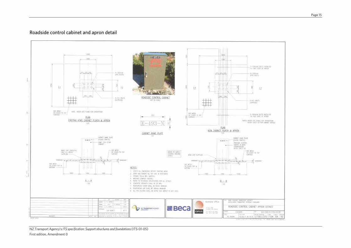
Roadside control cabinet and apron details 000-0000-0-7104-04-R0
Network node cabinet and apron details 000-0000-0-7104-06-R0
CCTV folding pole – general layout 000-0000-0-7104-45-R0
CCTV pole – general layout 000-0000-0-7104-46-R0
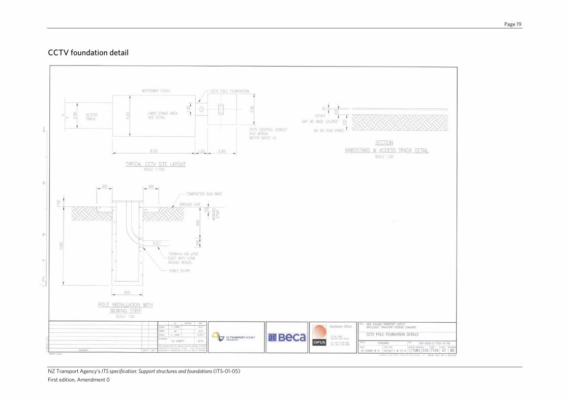
CCTV pole – foundation details 000-0000-0-7104-47-R0
VMS gantry - general layout 000-0000-0-7104-52-R0
VMS gantry - column details 000-0000-0-7104-53-R0
VMS gantry - truss details 000-0000-0-7104-54-R0
VMS gantry - sign frame and walkway detail 000-0000-0-7104-55-R0
VMS gantry - ladder and hoop detail 000-0000-0-7104-56-R0
VMS gantry - vandal barrier and gate 000-0000-0-7104-57-R0
VMS gantry - shoulder foundation 000-0000-0-7104-58-R0
VMS gantry - median foundation 000-0000-0-7104-59-R0
LCS gantry - general layout 000-0000-0-7104-60-R0
LCS gantry – backing boards 000-0000-0-7104-61-R0
LCS gantry - signal support details 000-0000-0-7104-62-R0
LCS gantry – lane signal unit support frame 000-0000-0-7104-63-R0
Disclaimer: The NZ Transport Agency (NZTA) and its employees, agents and consultants do not make any warranties or representations of any kind whatsoever in relation to the accuracy, currency or completeness of any of the content in the attached standard drawings and are under no obligation to update or correct any information shown on the drawings.
The attached standard drawings are made available strictly on the basis that the NZTA and its employees, agents and consultants exclude all liability for any claim made whatsoever (including negligence) by any party arising out of, or relating to the use of these standard drawings, regardless of how the claim arises.

Page 14
NZ Transport Agency’s ITS specification: Support structures and foundations (ITS-01-05) First edition, Amendment 0
Roadside control cabinet
Page 15
NZ Transport Agency’s ITS specification: Support structures and foundations (ITS-01-05) First edition, Amendment 0
Roadside control cabinet and apron detail

Page 16
NZ Transport Agency’s ITS specification: Support structures and foundations (ITS-01-05) First edition, Amendment 0
Network node cabinet and apron detail

Page 17
NZ Transport Agency’s ITS specification: Support structures and foundations (ITS-01-05) First edition, Amendment 0
CCTV folding pole – general layout

Page 18
NZ Transport Agency’s ITS specification: Support structures and foundations (ITS-01-05) First edition, Amendment 0
CCTV pole –general layout
Page 19
NZ Transport Agency’s ITS specification: Support structures and foundations (ITS-01-05) First edition, Amendment 0
CCTV foundation detail

Page 20
NZ Transport Agency’s ITS specification: Support structures and foundations (ITS-01-05) First edition, Amendment 0
VMS gantry – general layout

Page 21
NZ Transport Agency’s ITS specification: Support structures and foundations (ITS-01-05) First edition, Amendment 0
VMS gantry – column detail

Page 22
NZ Transport Agency’s ITS specification: Support structures and foundations (ITS-01-05) First edition, Amendment 0
VMS gantry – truss detail

Page 23
NZ Transport Agency’s ITS specification: Support structures and foundations (ITS-01-05) First edition, Amendment 0
VMS gantry – sign frame and walkway detail

Page 24
NZ Transport Agency’s ITS specification: Support structures and foundations (ITS-01-05) First edition, Amendment 0
VMS gantry – ladder and hoop detail

Page 25
NZ Transport Agency’s ITS specification: Support structures and foundations (ITS-01-05) First edition, Amendment 0
VMS gantry – vandal barrier and gate

Page 26
NZ Transport Agency’s ITS specification: Support structures and foundations (ITS-01-05) First edition, Amendment 0
VMS gantry – shoulder foundation

Page 27
NZ Transport Agency’s ITS specification: Support structures and foundations (ITS-01-05) First edition, Amendment 0
VMS gantry – median foundation

Page 28
NZ Transport Agency’s ITS specification: Support structures and foundations (ITS-01-05) First edition, Amendment 0
LCS gantry – general layout

Page 29
NZ Transport Agency’s ITS specification: Support structures and foundations (ITS-01-05) First edition, Amendment 0
LCS gantry – backing boards

Page 30
NZ Transport Agency’s ITS specification: Support structures and foundations (ITS-01-05) First edition, Amendment 0
LCS gantry – signal support detail

Page 31
NZ Transport Agency’s ITS specification: Support structures and foundations (ITS-01-05) First edition, Amendment 0
LCS gantry – lane signal unit support frame