ITER Central Solenoid
13
Building the World’s Largest Pulsed Superconducting Magnet ITER Central Solenoid
Transcript of ITER Central Solenoid
Building the World’s Largest Pulsed Superconducting Magnet
ITER Central Solenoid

What is ITER? What Will ITER Do?
• World’s largest scientific experiment being built by a partnership of 35 nations
• Plasma physics experiment to demonstrate the technological and scientific feasibility of magnetic fusion
• Produce 500 MW of power, which is 10 times the input heating power
• Demonstrate the integrated operation of technologies for a fusion power plant
• Achieve a deuterium-tritium plasma in which the reaction is sustained through internal heating
• Test tritium breeding
ITER is being built in southern FranceFRANCE
ITERCadarache
Photo credit: ITER Organization, May 2020
2 3

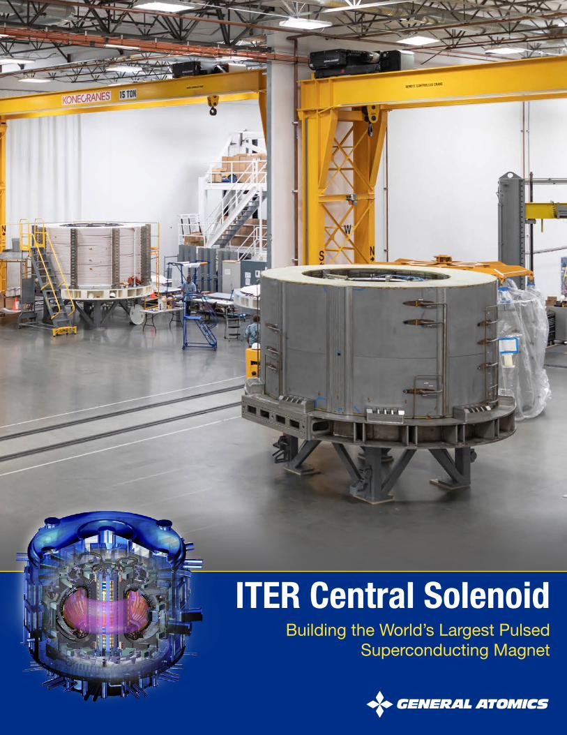
ITER Central SolenoidThe heart of the international fusion energy device
Central Solenoid Module FabricationFlows through 10 custom-built process stations
The Central Solenoid is the heart of ITER. The 5-story, 1,000-ton magnet will drive 15 million amperes of electrical current in ITER’s fusion plasma for stabilization. General Atomics (GA) is fabricating the modules in a dedicated facility in San Diego, CA.
It takes 22-24 months to manufacture each coil and prepare it for full current testing at 4.7 K
EACH MODULE
• 250,000 lb. (110-tonne)• Height: 7 feet (2.1 meters)• Diameter 13.6 feet (4.1 meters)• 3.6 miles (5.8 kilometers) of
steel-jacketed conductor• Conductor wound into 40 layers
CENTRAL SOLENOID ASSEMBLY
• 6 modules• Height: 59 feet (17.7 meters)• Diameter: 14.1 feet (4.3 meters)• Weight: 1,000 tons (900 tonnes)• Peak field strength: 13.1 Tesla• Stored energy capacity: 5.5 gigajoules
Station
1
Station
4
Station
7
Station
9
Station
8
Station
2
Station
5
Station
3
Station
6
Station
10
Conductor Receiving Inspection
Stack & Join/Helium Penetrations
Helium Piping
Winding
Reaction Heat Treatment
Final Test
Joint & Terminal Preparation
Turn Insulation
Turn Over ToolVacuum Pressure ImpregnationGround Insulation
Central SolenoidAssembly
Module
Stainless Steel-Jacketed Conductor
4 5

Central Solenoid Fabrication Facility
Completed High Bay Final Test Facility
• 6,000 sq. meters of temperature-controlled production space
• 0.6 meters thick concrete floors
• 1MW diesel generator
• 1MW cooling tower
• Liquid argon, liquid nitrogen, & liquid helium systems
• Gantry & bridge cranes
• Two 100+ horsepower air compressors
Production Facility Under Construction6 7

Receiving the Conductor Moving Module Between Stations
One of 54 spools of conductor received at the Central Solenoid production facility
Unloading a conductor spool from the delivery Conductor spools stored prior to winding Moving 250,000 lb. (110-tonne) module in facility requires air transporter
8 9
Station1

Winding the Module
Each Central Solenoid module will be fabricated from approximately 6,000 meters of niobium-tin (Nb3Sn) conductor. The production module segment here is wound from 900 meters of conductor into 14-turn pancakes with six layers.
Two spools loaded for winding
Station2
Bending to the required shape
10 11
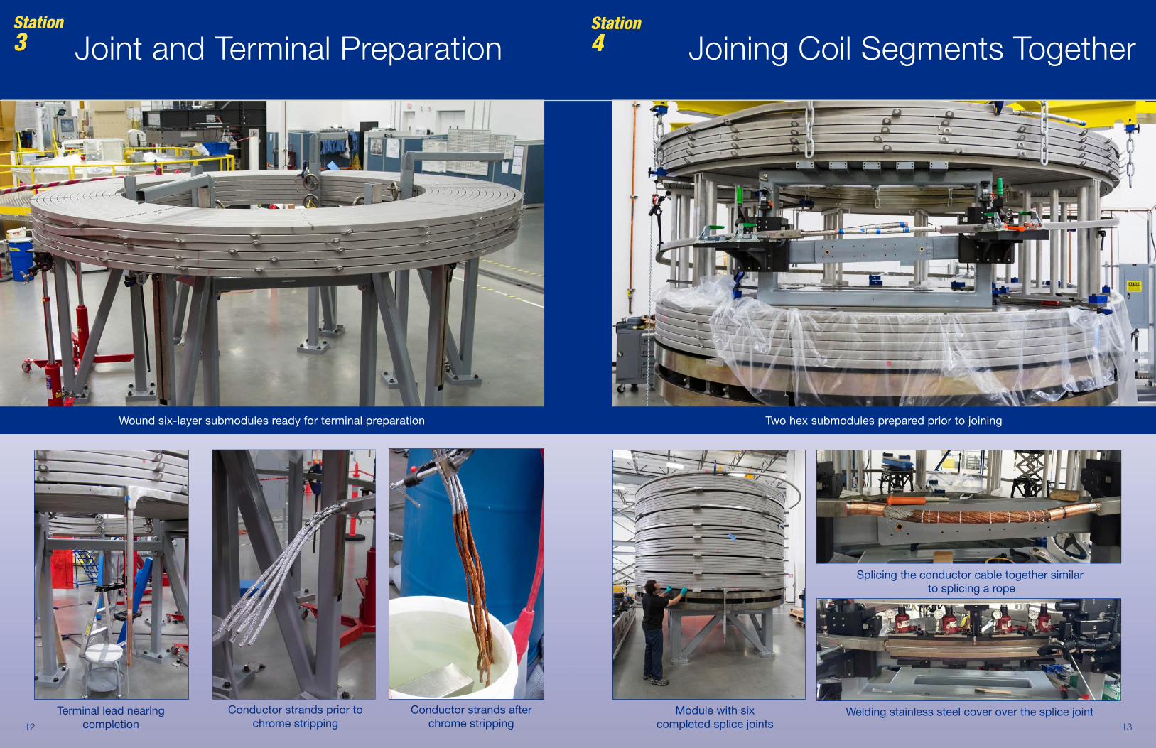
Joint and Terminal Preparation Joining Coil Segments Together
Terminal lead nearing completion
Station3
Station4
Wound six-layer submodules ready for terminal preparation Two hex submodules prepared prior to joining
Conductor strands prior to chrome stripping
Conductor strands after chrome stripping
Splicing the conductor cable together similar to splicing a rope
Welding stainless steel cover over the splice jointModule with six completed splice joints
Station4
12 13

Six ITER CS modulesin different fabrication stages:
Post resin injection on VPI station
Piping complete and ready for final test
Ground insulation
1
1
2
3
23
4
5
6
4
5
6
Post heat treatment
Stack and Join
After thermal cycle and power testing

Turn insulation of module nearing completion Automated heads wrapping fiberglass tape around the conductor
Air transporter placing module in furnace for heat treatment at 650°C (1200°F)
Technician inspecting module after heat treatment
Furnace closed for module heat treatment
Station6Reaction Heat Treatment Turn Insulation Station
Station5
Turn insulation station structure lifts and raises 110-tonne module and releases individual turns for insulation wrapping
16 17

Ground Insulation Station Vacuum Pressure Impregnation
VPI mold being placed over the module in preparation for resin injection
Technician inspects helium outlet pipe insulation on a completely insulated module
Station7
Helium inlet pipe with ground insulation
Module during ground insulation application
Station8
Completed module after resin injection
Module mold alongside resin tanks and mixing pump system for injecting 3,500 liters of resin to encapsulate
the module
18 19

Turnover of module in processThirty-nine helium pipes welded and insulated
to provide the supply and return for supercritical helium at 4.7 K
Module after piping installed
Helium PipingTurnover ToolStation9
Modules require rotation to exchange bases under coil and allow access for piping installation Technician applying insulation to piping on inner bore
20 21

Final Testing
Module in final test chamber50kA magnet charging power supply with 1GJ fast
discharge system including 7kV DC switch and dump resistor for full-current testing of CS modulesModule in final test chamber with camera system installed ready to
begin high voltage testing
1 kW supercritical helium supply system used for cooling the CS modules to 4.7 K
Station10
22 23

If you have unique, precise superconducting magnet fabrication needs, contact us:
John Smith, Director of Engineering and Projects
[email protected] | (858) 909-5276 | San Diego, California USA
www.ga.com/magnetic-fusion/iter-cs
October 20203202_1020