ITAR Restricted Data THEMIS Probe and PCA Overview Mission CDR 6/14 – 6/18/04 Integration and Test...
54
-
Upload
julian-sims -
Category
Documents
-
view
214 -
download
0
Transcript of ITAR Restricted Data THEMIS Probe and PCA Overview Mission CDR 6/14 – 6/18/04 Integration and Test...

ITAR Restricted Data
Integration and TestIntegration and Test
Marc Kaylor
301-902-4392

ITAR Restricted Data
I&T Focus on Major System Components to be VerifiedI&T Focus on Major System Components to be Verified
Launch Vehicle
Spacecraft/Probes
Ground SystemNetwork
Ground TrackingStation
Ground ControlCenter
(ITOS Databases)Instruments

ITAR Restricted Data
I&T ApproachOverview
I&T ApproachOverview
Bottoms Up, Modular Approach- Component Level and Subsystem ETU Verification prior to Integration- System Integration Aliveness Test to verify functionality
System Level Tests- Aliveness Test
- Verifies each probe operates including basic functionality and mechanical motion where applicable
- Functional Test- Verify every interface, command, telemetry point, and function- Uses EGSE as stimulus to test systems more in depth than Aliveness
- Comprehensive Performance Test- Measures performance on each subsystem- Demonstrates measurements of performance at a system level
- Mission / Orbits Simulation Test- Verifies system from simulation test modes at steady state orbits
- Environmental Tests- Verifies subsystem and system at design environment loads with margin
ITAR Restricted Data
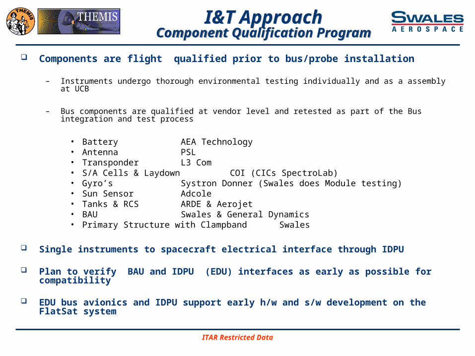
Components are flight qualified prior to bus/probe installation
– Instruments undergo thorough environmental testing individually and as a assembly at UCB
– Bus components are qualified at vendor level and retested as part of the Bus integration and test process
• Battery AEA Technology• Antenna PSL• Transponder L3 Com• S/A Cells & Laydown COI (CICs SpectroLab)• Gyro’s Systron Donner (Swales does
Module testing)• Sun Sensor Adcole• Tanks & RCS ARDE & Aerojet • BAU Swales & General Dynamics• Primary Structure with Clampband Swales
Single instruments to spacecraft electrical interface through IDPU
Plan to verify BAU and IDPU (EDU) interfaces as early as possible for compatibility
EDU bus avionics and IDPU support early h/w and s/w development on the FlatSat system
I&T ApproachComponent Qualification Program
I&T ApproachComponent Qualification Program

ITAR Restricted Data
Test Personnel and RolesTest Personnel and Roles
ITAR Restricted Data
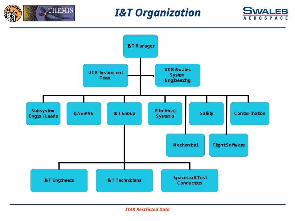
I&T OrganizationI&T Organization
SubsystemEngrs / Leads
QAE/PAE I&T GroupElectricalSystems
Safety Contamination
I&T Engineers I&T TechniciansSpacecraft Test
Conductors
UCB InstrumentTeam
I&T Manager
UCB/SwalesSystem
Engineering
Mechanical Flight Software

ITAR Restricted Data
Core TeamTest Personnel and Roles
Core TeamTest Personnel and Roles
I&T Manager- Responsible for Integration and Test Activities- Directs Test Activities- Coordinates Integration and Test Team- Prepares Facility and Test Stimuli
Systems Engineers- Plans System Tests and creates input parameters to tests- Writes system level test plans / procedures such as Comprehensive Performance Test, Aliveness Test, and
Orbits Simulation Test- Assist in the direction of test activities- Leads Verification Program and assures test objectives and requirements are verified and documented
Subsystem Leads / Engineers- Address technical issues regarding operation and design of subsystem- Works with Systems Engineering in verifying subsystem requirements through test
Quality Assurance Engineer- Cognizant of the execution of the test- Verifies quality of integration hardware, test data and equipment- Witness integration and sign-off of critical procedure steps
Spacecraft Test Conductors- In charge of operations to perform test procedure- Perform troubleshooting during test as required- Identify, report, and initiate corrective action for the flight hardware, database, or GSE- Disposition test anomalies- Conduct test briefings to the team

ITAR Restricted Data
Core TeamResponsible Equipment Engineer (REE) /
Subsystem Engineer
Core TeamResponsible Equipment Engineer (REE) /
Subsystem Engineer
Responsible Equipment Engineer (REE) / Subsystem Engineer
– The REE is the Subsystem Engineer who was responsible for the delivery of the test hardware to the l&T Team.
– The REE is responsible for performing testing to verify delivered hardware is fully operational prior to approving the start of the l&T process.
– The REE is required to attend the Test Readiness Review (TRR), Daily Test Coordination meetings and the Post Test Review (PTR).
– The REE has signature authority on the procedures and Work Order Authorizations (WOAs) applicable to the REE's hardware.
– Prior to signing the REE is to ensure that the testing activities are safe for the hardware, that the REE fully understands the testing activities as planned, and the expected results are accurate.
– The REE's signature is required on any black or red lines made to the procedure. • The signature is required before the black or red lines are to be performed.
– The REE is required to be present and observing all Flight testing. The REE is an active participant in the test operations but only in an oversight and support role. The REE is responsible for ensuring the hardware is never at risk, understanding and approving any deviations and to aid in the investigation of any anomalies or out of tolerance readings

ITAR Restricted Data
Core TeamSafety / Contamination
Core TeamSafety / Contamination
Safety Engineer
– The Safety Engineer is required to attend the Test Readiness Review (TRR), Daily Test Coordination meetings and the Post Test Review (PTR)
– This ensures that the Safety Engineer is cognizant of all testing operations
Contamination Engineer
– The Contamination Engineer is required to attend the Test Readiness Review (TRR), Daily Test Coordination meetings and the Post Test Review (PTR)
– This ensures that the Contamination Engineer is cognizant of all testing operations and potential impacts to the cleanliness of the spacecraft/instrument

ITAR Restricted Data
Facilities PlanFacilities Plan

ITAR Restricted Data
Swales 5015Swales 5015
Primary Probe Integration facility and the epicenter of our flight system development
5015 1st floor layout attachment shows separate work areas and multiple workstations to support our parallel probe I&T flow, includes class 100/10K cleanrooms, Flatsat, and harness labs
– Class 100K required in cleanrooms, Class 10K rules in effect when instrument interiors are exposed
– When the spacecraft is outside of the class 100,000 cleanroom it must be double bagged. 65-75 F, 30-60% RH
– No unique power requirements identified, standard 120VAC, 20A service should be adequate for each lab and zone. In addition zone 2 should be wired for 60A two phase service should we require a dedicated centralized UPS for sensitive GSE and grounding control
– Connectivity to the intranet and Internet required in each lab and zone. Zones 2, 2 and Lab C must also be connected to the THEMIS test net
– Existing portable crane required

ITAR Restricted Data
5015 Layout5015 Layout
OFFICEANTEROOM
ROLLUP DOOR
SLI
DIN
G D
OO
R
GOWNINGROOM
HVAC/FILTER ROOM
FACILITY ROOMLAB B
MECHANICALASSEMBLY
&BONDING
ROOM
LAB AHARNESS
&ELECTRICALASSEMBLY
ROOM
LAB CTESTBED
&FLIGHT S/WCHECKOUT
Staff Machine Shop
LO
BB
Y
ZONE 1
BR
BR
IWS #2
WB
IWS #1
WB
ZONE 2 ZONE 3
WB
EG
SE
1E
GS
E 2
WB
WB
WB
EG
SE
CH
EC
KO
UT
AR
EASHIPPING & REC
AREA
WB WB
WB
WB
MECH ASSYAREA (Hi-Bay)
P P
PP
P
WB
WB
WB
TYP PROBE & DOLLY
WB
WB
EGSEDEVELOPMENT
EGSE 3
WB
INSTRUMENTSTAGING AREA
WB
COMPONENTSTAGING AREA
WB WB
OVERFLOW IWS

ITAR Restricted Data
Swales 5015Mezzanine
Swales 5015Mezzanine
Second floor mezzanine area (not shown) planned for I&T staff office area and conference rooms. Includes areas for I&T team, Hammers SW Team, and Instrument Support Team
– Mezzanine must be wired to support phones Intranet, Internet and THEMIS test net connectivity
– Power requirements limited to standard 120VAC, 20A service
– Printer and photocopy machine available in lobby
Planned usage is as follows
– First floor highbay, labs and office has already begun
– First floor cleanroom 3Q04
– Second floor mezzanine 2Q04

ITAR Restricted Data
Network Security and AccessNetwork Security and Access
UCB
ITOS Front-End WSw/ Apache Server
LabVIEW/VirtualSat PC
THEMISFlightHW
ITOS Sub-SystemWorkstations
Personal PCsOffice PC
Windows PCfor I&T Support
Visitor PCs
SWALESNAS1
File Server
Internet
Swales I&Tat GSFC
Hammers
Firewall(Swales managed,in addition to ODIN)
Zone 1A. THEMIS Secure:Zone 1 network ports see only otherworkstations in the secure zone locally andremote locations (GSFC, UCB, andHammers) configured with secure fixed IPaddresses. The Apache server will beaccessibly by fixed IP Address directedthrough the Swales firewall.
Zone 1B. Swales I&T @ GSFC
Swales Firewall Access:Remote access through the Swales Firewall to theTHEMIS Secure Zone is through encrypted site-to-siteVPN tunnels only. All devices located at GSFC,Hammers and UCB which will participate in the site-to-site VPN are expected to be dedicated, isolated from allother networks at those remote sites.
File Server: Config, DB, Proc, and Data Filesare stored on the NAS1 server and accessibleto WS with Swales VPN access. The server isbacked up daily. A terabyte of space is beingplanned for ops support.
Network Failures:In case of a NAS1 or Network failures real-timetesting will continue. Access to some archived testdata will be temporarily un-available along with testprocedure and other CM files.
HammersFirewall
UCBFirewall
ITOS Front-End WSw/ Apache Server
LabVIEW/VirtualSat PC
THEMISFlightHW
ITOS Sub-SystemWorkstations
Windows PCfor I&T Support
Ethernet
Ethernet
Ethernet
SwalesFirewall
EthernetEthernet
Zone 2. Swales Network and Servers:Zone 2 ports have the same access as generalSwales (Email, web, etc). Approved laptops canbe added and removed as needed.
Zone 3. Hammers and UCB Net

ITAR Restricted Data
Probe Carrier Integration FacilityProbe Carrier Integration Facility
High Bay in Swales Building 11310
– The probe carrier will be fully integrated in this facility.
– There are no requirements to maintain the this hardware assembly in a cleanroom at a Class 100K
– 40’ x 40’ area needed for PC and shipping container
– Same facility that we plan to use to manufacture the probe primary structure components (decks, side and quarter panels)
– Has loading dock, clean areas, access control, bonded storage, machine shop, tooling, lots of staff etc
– No facility modifications identified at this time, expect to use as is
– First use is expected in the 3Q04

ITAR Restricted Data
Swales 5016 HighbaySwales 5016 Highbay
ETU Clampband Requirements (Inside 5016)
– 25’ X 25’ area under beam crane – Overhead crane required –
existing ½ ton beam is acceptable – need hoist
– 65-75 F, 30-60 % RH (TBR)– Standard 120VAC, 20 A service (6
outlets)– Phone and network access in
clampband corner– Capability to partition work areas– 2 work tables one with provisions
for ESD ground– Secure cabinet and/or cage
storage– Planned first use is 1 March 2004
for ETU clampband testing

ITAR Restricted Data
Facilities / Security ControlFacilities / Security Control
FACILITY ACCESS REQUIREMENTS
– Personnel supporting the THEMIS activity will require authorization by the I&T Manager and/or the THEMIS Program Manager for access to the facilities where the activities occur.
– Access to the Swales 5015 Building will be controlled by the use of a key card. QA will maintain a current access log of personnel working on or in the general area of the spacecraft.
– Swales has current arrangements for off duty police patrols from 6PM-6AM weekdays and 24/7 on weekend

ITAR Restricted Data
Cleanroom Support / Contamination
Cleanroom Support / Contamination
Mission level Contamination Control Plan from UCB Baselined– SST, and ESA instrument drive mission contamination requirements– ESA and SST Instruments arrive covered and remain that way except
for TV testing and launch– GN2 purge required, 24 hour interruptions OK– Surface cleanliness levels of 500A specified
The general set of contamination critical surfaces identified in the Themis spacecraft and the instruments include– ESA Microchanel Plates OSRs– ESA Gold-Black Surfaces– SST Detectors– Thermal control surfaces– Solar panels– Sun sensor

ITAR Restricted Data
Contamination PlanContamination Plan
The requirement is to maintain the cleanroom at a Class 100K – Historically, the facility has performed as a Class 10K
– GN2 purge lines and Flow Control for the ESA and SST
– Cleanroom Supplies / Cleanroom Monitoring Equipment
• Cleanroom garments Cleanroom gloves• Cleanroom wipes Cleaning solvents• Paper and report covers Portable vacuum equipment• Witness plates, stainless steel Room air particle counter • Tape-lift supplies Cleanroom bagging material• High purity gaseous nitrogen (GN2) bottles (UCB provided)• GN2 purge cart/lines/controls (UCB provided)
– Probe shall be bagged when ever it is necessary to relocate the probe outside of the cleanroom for any reason

ITAR Restricted Data
Cleanroom Personnel Requirements
Cleanroom Personnel Requirements
Garment Requirements
In Control Area
Prior to instrument integration or instrument bagged (Class 100,000)
Smock
Face Hood
Beard Cover or Eye Hood if facial hair
Gloves
Shoe Cover
After instrument integration and instrument exposed (Class 10,000)
Bunny Suit
Face Hood + Beard Cover or Eye Hood
Gloves
Booties
ITAR Restricted Data
GSFC ENVIRONMENTAL TEST FACILITIES
GSFC ENVIRONMENTAL TEST FACILITIES
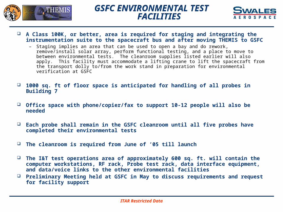
A Class 100K, or better, area is required for staging and integrating the instrumentation suite to the spacecraft bus and after moving THEMIS to GSFC
– Staging implies an area that can be used to open a bay and do rework, remove/install solar array, perform functional testing, and a place to move to between environmental tests. The cleanroom supplies listed earlier will also apply. This facility must accommodate a lifting crane to lift the spacecraft from the transport dolly to/from the work stand in preparation for environmental verification at GSFC
1000 sq. ft of floor space is anticipated for handling of all probes in Building 7
Office space with phone/copier/fax to support 10-12 people will also be needed
Each probe shall remain in the GSFC cleanroom until all five probes have completed their environmental tests
The cleanroom is required from June of ’05 till launch
The I&T test operations area of approximately 600 sq. ft. will contain the computer workstations, RF rack, Probe test rack, data interface equipment, and data/voice links to the other environmental facilities
Preliminary Meeting held at GSFC in May to discuss requirements and request for facility support
ITAR Restricted Data
I&T FlowI&T Flow

ITAR Restricted Data
I&T FlowProbe
I&T FlowProbe
Assemble PrimaryStructure
Sine Burst Test &Modal Signature,Strength Qualified
Structure
Disassemble-S/A’s to Vendor,Bottom Deck to
Vendor
Cell Laydown &Wiring, Test &
Qual
Baseplate Mockupto RCS Vendor RCS Component
Assembly
Bottom Deckto RCS Final
Assembly & Test
Back at SAI forHarness &
Thermal Install
Bottom Deck
Panels
RCS
Component MassMockups
Tanks to RCSVendor
QualifiedSeparation System
Install FlightBAU
Install workhorsebattery
Qualified S/A Top,Bottom, & Side
Panels
Install Sun Sensor& Gyro’s
InstallTransponder
Perform BaselineCPT
Perform1st CPT
EMI Self Com TestSCM & FGM
Boom 1st MotionTest
Mag SurveyS/A Illumination
Test
Store Panels tillneeded
Probe A Ready forEnvironmental
Testing
Install TopDeck &Corner
Panels andAxial Boom
Instrument SuiteArrives at Swales
Unpack & InspectInstrument Suite
Perform Functionalon Instrument
Suite
Hold IntegrationReadiness Review
with InstrumentTeam
Integrate IDPU &Instrument cables
with BAU
Integrate ESAInstrument
Integrate EFIInstruments
Radial / AxialIntegrate SSTs Integrate SCM
Integrate FGMSide Panel
Closeout & InstallSide Panel Arrays
Install S-BandAntenna
Install Top &Bottom S/A’s
Thermal CloseoutsVerify Range andMotion of SCM &
FGM Booms
Instrument Activities
ITAR Restricted Data
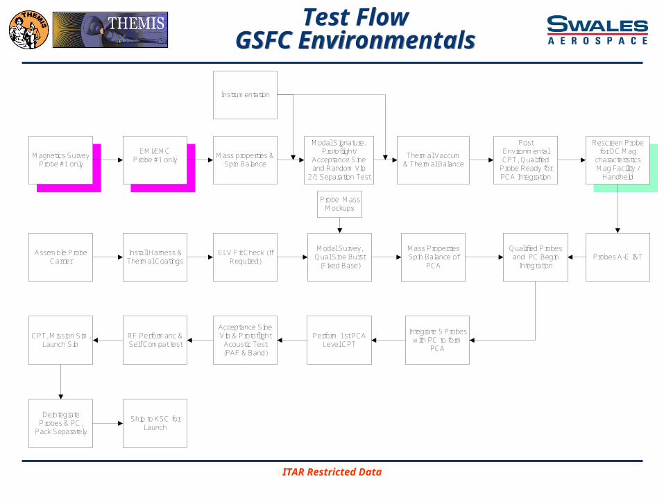
Test FlowGSFC Environmentals
Test FlowGSFC Environmentals
Mass properties &Spin Balance
Modal Signature,Protoflight/
Acceptance Sineand Random Vib
2/1 Separation Test
Thermal Vaccum& Thermal Balance
PostEnvironmentalCPT, Qualified
Probe Ready forPCA Integration
Assemble ProbeCarrier
Probe MassMockups
Install Harness &Thermal Coatings
ELV Fit Check (IfRequired)
Modal Survey,Qual Sine Burst
(Fixed Base)
Qualified Probesand PC Begin
Integration
Integrate 5 Probeswith PC to form
PCA
Perform 1st PCALevel CPT
Acceptance SineVib & Protoflight
Acoustic Test(PAF & Band)
RF Performanc &Self Compat test
CPT, Mission Sim,Launch Sim
DeintegrateProbes & PC,
Pack Separately
Probes A-E I&T
Ship to KSC forLaunch
EMI/EMCProbe #1 only
Magnetics SurveyProbe #1 only
Mass PropertiesSpin Balance of
PCA
Instrumentation
Rescreen Probefor DC Mag
characteristicsMag Facility /
Handheld
ITAR Restricted Data
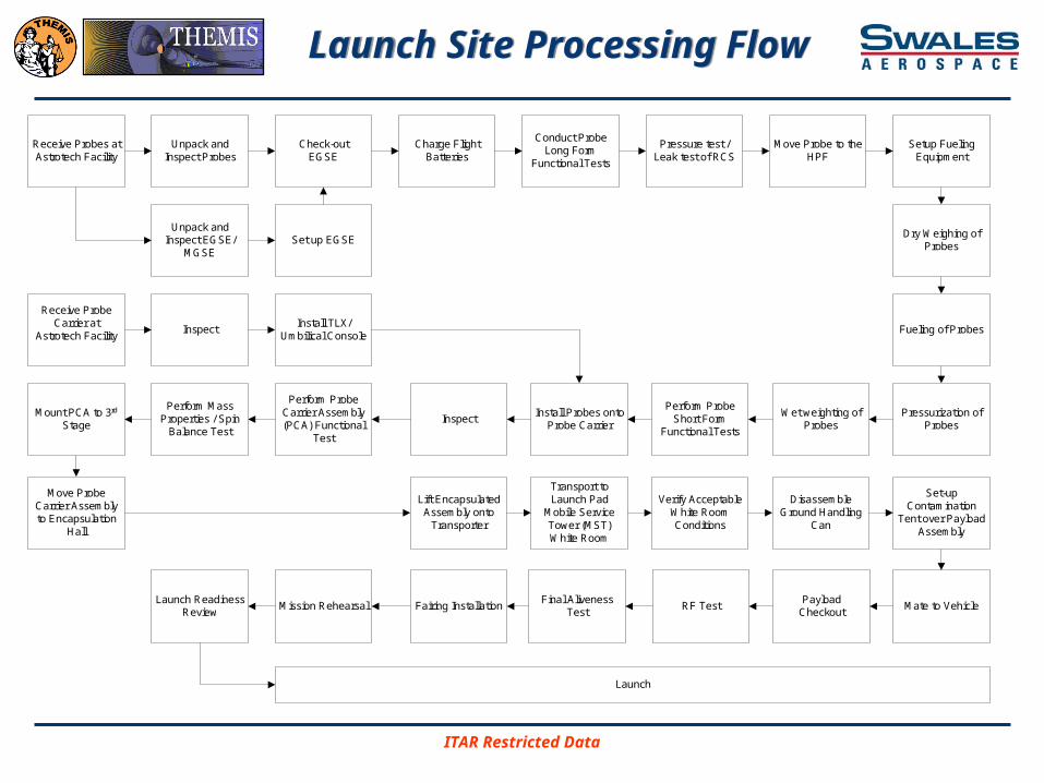
Launch Site Processing FlowLaunch Site Processing Flow
Receive Probes atAstrotech Facility
Unpack andInspect Probes
Install TLX/Umbilical Console
Perform ProbeShort Form
Functional Tests
Charge FlightBatteries
Receive ProbeCarrier at
Astrotech FacilityInspect
Perform ProbeCarrier Assembly(PCA) Functional
Test
Perform MassProperties / Spin
Balance Test
Move ProbeCarrier Assemblyto Encapsulation
Hall
Lift EncapsulatedAssembly onto
Transporter
Transport toLaunch Pad
Mobile ServiceTower (MST)White Room
Mate to VehicleRF TestPayload
Checkout
Verify AcceptableWhite RoomConditions
DisassembleGround Handling
Can
Conduct ProbeLong Form
Functional Tests
Pressure test /Leak test of RCS
Install Probes ontoProbe Carrier
Inspect
Fairing InstallationFinal Aliveness
TestLaunch Readiness
Review
Launch
Mission Rehearsal
Dry Weighing ofProbes
Mount PCA to 3rd
Stage
Set-upContamination
Tent over PayloadAssembly
Unpack andInspect EGSE/
MGSE
Check-outEGSE
Set up EGSE
Move Probe to theHPF
Setup FuelingEquipment
Fueling of Probes
Pressurization ofProbes
Wet weighting ofProbes
ITAR Restricted Data
INTEGRATION PROCESSINTEGRATION PROCESS

ITAR Restricted Data
Work AuthorizationWork Authorization
Manufacturing activities will begin when a Work Order Authorization (WOA) is received and accepted
Production operations shall be conducted in accordance with approved and released documentation (e.g. work instructions, drawings, specifications, standard operating procedures, bill of materials, etc.)
Applicable drawings (properly checked approved and issued through Configuration Management), specifications, and/or procedures must be available for all work requests
Any changes to the applicable documents reflected in work orders must be documented on an approved engineering change order, as a minimum

ITAR Restricted Data
WOA ContWOA Cont
Equipment
– All special equipment (e.g. tooling, jigs, inspection fixtures, etc.) required by the production process shall be clearly specified in the work instructions. Any unique handling/use instructions shall also be identified

ITAR Restricted Data
WOA EntryWOA Entry

ITAR Restricted Data
WOA EntryWOA Entry

ITAR Restricted Data
WOA EntryWOA Entry

ITAR Restricted Data
WOA ReviewWOA Review
ITAR Restricted Data
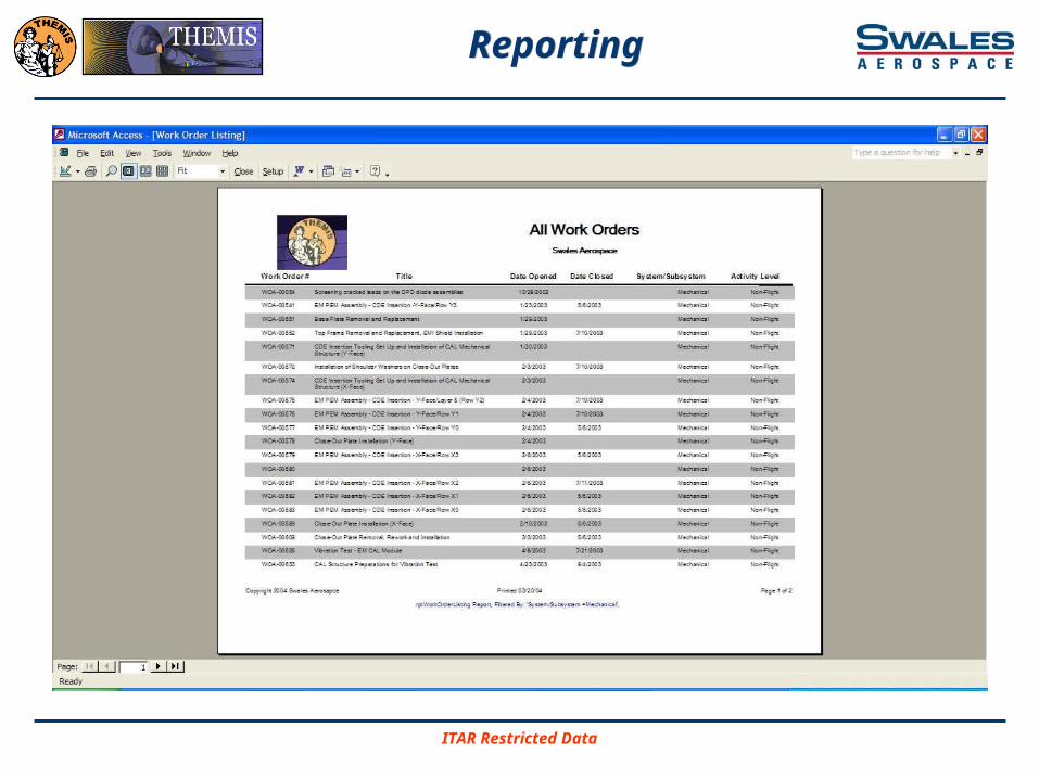
ReportingReporting

ITAR Restricted Data
Problem RecordsProblem Records

ITAR Restricted Data
Test FlowTest Flow

ITAR Restricted Data
Typical Electrical I&T FlowTypical Electrical I&T Flow
HardwareDelivered
Review &Inspection
HardwareFormally
Delievered toI&T
EICIT IVT
ATLong Form
Test CPT
Has the HDWbeen modified
ordissasembled?
Has the HDWbeen
removed butnot
modified?
Safe to Mate
YES
YES
Electrical Interface Continuity and Isolation Test (EICIT)
Interface Verification Test (IVT)
Aliveness Test (AT)
Safe To Mate (STM) (only as required)
Limited Performance Test (LPT)
Comprehensive Performance Tests (CPT)

ITAR Restricted Data
I&T Test Documentation Summary I&T Test Documentation Summary
Test Procedure– Document which details the prerequisites, test configuration,
requirements and steps to demonstrate a set of requirements
WOA– A document which details in incremental steps an operation to be
completed or references a Test Procedure
Test Summary Report– A memo which documents the completion of a test, detailing any
anomalies
Final Test Report– A formal document which details the results of the test, details the
analysis of the data collected during the test, details the status of the procedure, details the rationale for requirements being satisfied, and publishes for the record the complete as run test procedure and data

ITAR Restricted Data
Test ProceduresTest Procedures
The I&T test procedures will be prepared in accordance with the approved I&T Test Plan
The test procedures are developed by the I&T Engineering Group and submitted to the project for review and approval. Once approved all procedures will be under CM control. The basic I&T test procedures that will be developed for each test article are as follows
– Electrical Interface Continuity and Isolation Test (EICIT)
– Interface Verification Test (IVT)
– Aliveness Test (AT)
– Safe To Mate (STM) (only as required)
– Limited Performance Test (LPT)
– Comprehensive Performance Tests (CPT)

ITAR Restricted Data
Functional TestsFunctional Tests
Aliveness Test (AT)– The AT is a short test in which the test article(s) is powered on for
health and status checks. Telemetry is then verified to be within acceptable ranges
Limited Performance Tests (LPT) – A demonstration that the primary hardware and software meet their
performance requirements within allowable tolerances. The test shall demonstrate operation of primary circuitry and satisfactory performance in the primary operational mode
Comprehensive Performance Tests (CPT) – A detailed demonstration that the hardware and software meet their
performance requirements within allowable tolerances. The test shall demonstrate operation of all redundant circuitry and satisfactory performance in all operational modes
ITAR Restricted Data
Verification TestConfiguration Control
Verification TestConfiguration Control
Configuration control shall be maintained for each test conducted
At a minimum the following data shall be captured
– Revision level of all EGSE software and databases
– Revision level of all FSW
– Revision level / serial no. of EGSE hardware
– Revision level of Flight Hardware System/Subsystem components

ITAR Restricted Data
Verification PlansVerification Plan and Envr. Test Spec
Verification PlansVerification Plan and Envr. Test Spec
THEMIS Verification Plan and Environmental Test Specification Document Number SAI-SPEC-1164
Objectives of the Verification Program
– Provide assurance that specified mission objectives are met– Provide assurance that hardware will meet specific functional / performance,
interface and safety requirements– Provide confidence that the probes will survive the environments imposed during the
launch and mission sequence– Determine operating and performance characteristics from simulated mission
environments
Verification Planning of the Instruments – Documented in the THEMIS Instrument Payload Verification Plan and Environmental
Test Specification Document No. THM-SYS-005 Written by UCB

ITAR Restricted Data
Verification PlansSummary of Required Tests
Verification PlansSummary of Required Tests
THEMIS Verification Plan and Environmental Test Specification Document Number SAI-SPEC-1164
Tests are conducted at the Component Level, Subsystem Level, Integrated Probe System Level, and Integrated Probe Carrier Level
Summary of Tests and Analysis for the applicable Components / Systems include
– Comprehensive Performance Test (CPT)– Functional / Performance Test– Electromagnetic Compatibility Test– Mission Simulation Test– Thermal Balance Test– Thermal Vacuum Test– Alignment Demonstration– Sine Sweep Vibration Test– Separation Shock Test– Magnetic Properties Demonstration – Mass Properties Measurement– Acoustic Test– Radiation Susceptibility Analysis– Pressure Profile Verification Analysis

ITAR Restricted Data
ENVIRONMENTAL TEST USING GSFC
ENVIRONMENTAL TEST USING GSFC
The GSFC facilities have been selected as the baseline approach to be used for environmental testing. The environmental test facilities will consist of
Magnetics EMC/ EMI Mass Properties, Weight, Center-of-Gravity (C.G.), Moment-of-
Inertia (MOI) Vibration Thermal Vacuum / Thermal Balance (TV/TB) RF Compatibility Acoustics
GSFC Facilities within 7 miles & Swales staff has worked with GSFC team for many years
ITAR Restricted Data
Magnetics TestingMagnetics Testing
Component testing previously identified and evaluated by UCLA
Probe level self compatibility with onboard FGM and SCM augmented by external magnetometer GSE in a quiet lab here at Swales baseline
Test program designed to verify magnetics requirements specification and guidelines document issued by UCB
– Draft document under UCB review
High fidelity testing at GSFC Magnetics test facility base lined for first probe with the possibility of running two probe for signature comparison
– Visit to the mag test site facility was very informative and generated the possibility of additional test configurations and EGSE needed
– The implementation and impacts of adding compensations magnets to be discussed with Swales mechanical

ITAR Restricted Data
ELECTROMAGNETIC TESTINGELECTROMAGNETIC TESTING
The THEMIS Satellite will be tested for EMC/EMI compatibility in the EMC facility at GSFC Building 7
A self compatibility functional test matrix will be used to exercise each electronic box or function in a noise generation mode while all others are setup in their quiet modes
The objective is to determine if any box or component is sensitive to external RF or electromagnetic emissions, either conducted or radiated
Another objective is to plot an electromagnetic signature of the satellite in its various operating modes
These RF sources will be run based on requirements given in the MIL-STD-461C/462C and will be modified to test any elevated RF emissions (above the levels in the MIL-STD) to simulate transmitters at the launch site

ITAR Restricted Data
Spin Balancing of ProbesSpin Balancing of Probes
Miller table at GSFC will be used to test and iterate to final static and dynamic balance point
UCB has been tasked to make magnetometer booms self balancing when deployed
Swales evaluating the possibility to obtain spin balance of booms both in stowed and deployed configurations prior boom integration onto probe
Masses/washers made of tungsten will be used
Mass properties for the probe (fueled) and stacked PCA shall be performed at AstroTech

ITAR Restricted Data
VibrationVibration
Vibration and shock testing shall be perform at GSFC test facilities
Probes shall be secured to the table via a payload attachment flange
EGSE and racks to be located Upstairs
The tests shall be conducted with the probe “ON”
Probe #1 to be tested to protoflight durations
Shock testing to be conducted via separation firing of the clamp band
Post “Pop and Catch” of the booms was a review question raised during preliminary conformation meetings
ITAR Restricted Data
Separation System Acceptance Testing
Separation System Acceptance Testing
Single firing functional test (Probe 1 twice)
– Performed at Separation System Assembly level
Single firing functional test (performed after delivery to Probes)
– Performed after each flight Probe vibration

ITAR Restricted Data
Thermal Vacuum TestingThermal Vacuum Testing
Probe #1 to be tested alone
Evaluate the ability to test two Probes in the same chamber– Thermal balance / stability with having two probes– Number of environments to be supported– Cold plate / TCUs needed to support environment– Thermal test fixture design
Hot biased thermal design depends on solar heat absorbed on top deck VDG. The hot case thermal balance needs to be conducted using a solar simulator to create the hot top deck boundary condition. Using a heater controlled elevated deck temperature does not validate this design condition
Multiple thermal balance cases need to be run to develop correlated thermal model – at least 6 cases for Probe #1
Thermal balance case for Probes #2-5 to be reduced with in correlated results of Probe #1
Thermocouple instrumentation to be removed after TV test… – This implies that solar arrays will need to be removed prior to test and after test for removal
Hot / Cold case performance with CTV to be evaluated so as not to impact test durations

ITAR Restricted Data
RF COMPATIBILITYRF COMPATIBILITY
The RF Compatibility Test Van (CTV) will be used at GSFC to test the RF compatibility of THEMIS RF subsystems with the Ground Network (GN) and the Space Network (SN)/Tracking and Data Relay Satellite System (TDRSS)
The CTV test will consist of testing the S-Band transponder at different data rates and different data coding modes for telemetry downlink, at 1 kbps for command uplink, and for ranging compatibility. Additional S-Band transponder testing will be done at multiple data rates with the TDRSS
UCB mission Ops has the lead to coordinate this testing
Its expected to support this test during probe thermal vacuum testing
ITAR Restricted Data
ScheduleSchedule

ITAR Restricted Data
Manpower Planthru Phase #1
Manpower Planthru Phase #1
Note: There is approximately and additional 11 subsystem staff that are not included in the I&T Team head count. In addition UCB Instrument Team & MOC staff support I&T
An additional EGSE Rack has been added based on re-evaluation program goals & schedule

ITAR Restricted Data
Manpower Planthru Phase #2
Manpower Planthru Phase #2
ITAR Restricted Data
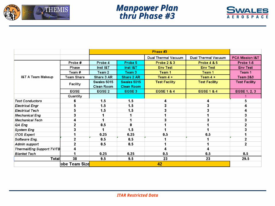
Manpower Planthru Phase #3
Manpower Planthru Phase #3