
IT6601 MOBILE COMPUTING
157
IT6601 MOBILE COMPUTING UNIT – IV Dr.A.Kathirvel, Professor and Head, Dept of IT Mrs. D. Anbarasi, Asst. Professor/IT Anand Institute of Higher Technology, Chennai
-
Upload
anand-institute-of-higher-technology-chennai -
Category
Engineering
-
view
1.772 -
download
2
Transcript of IT6601 MOBILE COMPUTING

IT6601 MOBILE COMPUTING
UNIT – IV
Dr.A.Kathirvel, Professor and Head, Dept of IT
Mrs. D. Anbarasi, Asst. Professor/IT
Anand Institute of Higher Technology, Chennai

Unit - IV
MOBILE AD-HOC NETWORKS
Ad-Hoc Basic Concepts – Characteristics – Applications –
Design Issues – Routing – Essential of Traditional Routing
Protocols – Popular Routing Protocols –
Vehicular Ad-Hoc networks ( VANET) – MANET Vs
VANET – Security
*Prasant Kumar Pattnaik, Rajib Mall, “Fundamentals of Mobile Computing”, PHI Learning Pvt. Ltd, New Delhi
2

Synopsis
Ad-Hoc Basic Concepts
Characteristics of MANETs
Applications of MANETs
MANET Design Issues
Routing
Essential of Traditional Routing Protocols
Popular Routing Protocols
Vehicular Ad-Hoc networks ( VANET)
MANET Vs VANET
Security
3

Ad-Hoc Basic Concepts
Multi-hop Wireless Networks (MHWNs)
It is defined as a collection of nodes that communicate
with each other wirelessly by using radio signals with a
shared common channel.
which forms a temporary network without the aid of
centralized administration or standard support devices
regularly available as conventional networks.
There are several names for MHWNs; it could be
called packet radio network, Ad-Hoc network or
mobile network.
4

Ad-Hoc Basic Concepts
Multi-hop Wireless Networks (MHWNs)
A mobile ad hoc network (MANET) is a continuously self-
configuring, infrastructure-less network of mobile devices
connected without wires.
A mobile ad-hoc network (MANET) is an ad-hoc network
but an ad-hoc network is not necessarily a MANET.
MHWNs
MHWNs MHWNs MHWNs
5
Types of MANET
Vehicular Ad hoc Networks (VANETs)
Smart Phone Ad hoc Networks (SPANs)
Internet based mobile ad hoc networks
(iMANETs)
Military / Tactical MANETs
6
Characteristics of MANET
Autonomous and infrastructureless
Multi-hop routing
Dynamic network topology
Device heterogeneity
Energy constrained operation
Bandwidth constrained variable capacity links
Limited physical security
Network scalability
Self-creation, self-organization and self-administration
7

Applications of MANET
Tactical networks
Emergency services
Commercial and civilian environments
Home and enterprise networking
Education
Entertainment
Sensor networks
Context aware services
Coverage extension
8

MANET Design Issues
Unpredictability of Environment
Unreliability of Wireless Medium
Resource-Constrained Nodes
Dynamic Topology
Transmission Errors
Node Failures
Link Failures
Route Breakages
Congested Nodes or Links
9

Routing
To find and maintain routes between nodes in a
dynamic topology with possibly uni-directional
links, using minimum resources.
Routing Protocols
Proactive protocols (table-based)
Traditional distributed shortest-path
protocols.
Based on periodic updates. High routing
overhead.
10

Routing
Reactive (on-demand) protocols
Discover routes whenever needed to
reduce routing overhead.
No route created a priori. It is created
in response to a need. But introduces
delay.
Source-initiated route discovery.
Hybrid protocols
11

Routing Algorithms
Objective of routing algorithms is to calculate
‘good’ routes
Routing algorithms for both datagrams and virtual
circuits should satisfy:
Correctness
Simplicity
Robustness
Stability
Optimality
Fairness
Impossible to satisfy everything at the same time
12

Elements of Routing Algorithms
Optimization Criteria
Number of Hops
Cost
Delay
Throughput
Decision Time
Once per session (VCs)
Once per packet (datagram)
Decision Place
Each node (distributed routing)
Central node (centralized routing)
Sending node (source routing) 13

Shortest-Path Routing
Routing algorithms generally use a shortest path
algorithm to calculate the route with the least cost.
Three components
Measurement Component: Nodes (routers)
measure the current characteristics such as delay,
throughput, and “cost”
Protocol: Nodes disseminate the measured
information to other nodes
Calculation: Nodes run a least-cost routing
algorithm to recalculate their routes
14

Traditional Routing Protocols
There are two basic approaches to least-cost
routing in a communication network
There are two basic approaches to shortest-
path routing
Link State Routing
Distance Vector Routing
15

Approaches to Shortest Path Routing
Link State Routing
Each node knows the distance to its neighbors
The distance information (=link state) is broadcast to all
nodes in the network
Each node calculates the routing tables independently
Distance Vector Routing
Each node knows the distance (=cost) to its directly connected
neighbors
A node sends a list to its neighbors with the current distances
to all nodes
If all nodes update their distances, the routing tables
eventually converge
16

Distance Vector
Each node maintains two tables:
Distance Table: Cost to each node via each
outgoing link
Routing Table: Minimum cost to each node and
next hop node
Nodes exchange messages that contain
information on the cost of a route
Reception of messages triggers recalculation
of routing table
17

Distance Vector Algorithm: Tables
l (v,w) cost of link (w,v)
C d(v,w) cost from v to d via w Dd(v) minimum cost from v to d
to
Cd(v,n)C
d(v,w)
nw
n
v w dl(v,w)
d
via
to
Dd(v)n
costvia(next hop)
d
Distance Table RoutingTable
Note: In the figure,
Cd(v,w)<Cd(v,n) and,
therefore,
Dd(v) = Cd(v,n)
18

Distance Vector Routing
Entries of routing tables can change while a packet is
being transmitted. This can lead to a single datagram
visiting the same node more than once (Looping)
If the period for updating the routing tables is too
short, routing table entries are changed before
convergence (from the previous updates) is achieved
Example: The ARPANET used a Distance Vector
algorithm with an update period of <1 sec. Due to the
instability of routing, the ARPANET switched in
1979 to a link state routing algorithm
19

20
Characteristics of DV Routing
Periodic Updates: Updates to the routing tables are sent at
the end of a certain time period. A typical value is 90
seconds.
Triggered Updates: If a metric changes on a link, a router
immediately sends out an update without waiting for the
end of the update period.
Full Routing Table Update: Most distance vector routing
protocol send their neighbors the entire routing table (not
only entries which change).
Route invalidation timers: Routing table entries are invalid
if they are not refreshed. A typical value is to invalidate an
entry if no update is received after 3-6 update periods.

21
Distance Vector vs Link State Routing
With distance vector routing, each node has information only
about the next hop
Node A: to reach F go to B
Node B: to reach F go to D
Node D: to reach F go to E
Node E: go directly to F
Distance vector routing makes
poor routing decisions if
directions are not completely
correct
(e.g., because a node is down).
If parts of the directions incorrect, the routing may be incorrect until the routing
algorithms has re-converged.
A B C
D E F

22
Distance Vector vs. Link State Routing
In link state routing, each node has a complete map of the
topology
If a node fails, each
node can calculate
the new route
Difficulty: All nodes need to
have a consistent view of the
network
A B C
D E F
A B C
D E F
A B C
D E F
A B C
D E F
A B C
D E F
A B C
D E F
A B C
D E F

Link State Routing
Each node must
discover its neighbors
measure the delay (=cost) to its neighbors
broadcast a packet with this information to all other
nodes
compute the shortest paths to every other router
The broadcast can be accomplished by flooding
The shortest paths can be computer with Dijkstra’s
algorithm
23

24
Link State Routing: Basic principles
Each router establishes a relationship (“adjacency”) with
its neighbors
Each router generates link state advertisements (LSAs)
which are distributed to all routers
LSA = (link id, state of the link, cost, neighbors of
the link)
Each router maintains a database of all received LSAs
(topological database or link state database), which
describes the network has a graph with weighted edges
Each router uses its link state database to run a shortest
path algorithm (Dijikstra’s algorithm) to produce the
shortest path to each network

25
Link State Routing: Properties
Each node requires complete topology
information
Link state information must be flooded to all
nodes
Guaranteed to converge
26
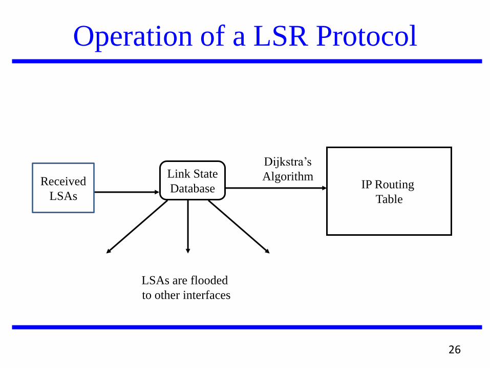
Operation of a LSR Protocol
IP Routing
Table
Dijkstra’s
Algorithm Link State
Database
LSAs are flooded
to other interfaces
Received
LSAs

27
Dijkstra’s Shortest Path Algorithm
Input: Graph (N,E) with
N the set of nodes and E N × N the set of edges
dvw link cost (dvw = infinity if (v,w) E, dvv = 0)
s source node.
Output: Dn cost of the least-cost path from node s to node n
M = {s};
for each n M
Dn = dsn;
while (M all nodes) do
Find w M for which Dw = min{Dj ; j M};
Add w to M;
for each n M
Dn = minw [ Dn, Dw + dwn ];
Update route;
enddo

MANET vs. Traditional Routing
Every node is potentially a router in a MANET, while
most nodes in traditional wired networks do not route
packets
Nodes transmit and receive their own packets and, also,
forward packets for other nodes
Topologies are dynamic in MANETs due to mobile nodes,
but are relatively static in traditional networks
Routing in MANETs must consider both Layer 3 and
Layer 2 information, while traditional protocols rely on
Layer 3 information only
Link layer information can indicate connectivity and
interference
28

MANET vs. Traditional Routing
MANET topologies tend to have many more
redundant links than traditional networks.
A MANET “router�” typically has a single
interface, while a traditional router has an
interface for each network to which it connects
Routed packet sent forward when transmitted, but
also sent to previous transmitter
Channel properties, including capacity and
error rates, are relatively static in traditional
networks, but may vary in MANETs
29
MANET vs. Traditional Routing
Interference is an issue in MANETs, but not in
traditional networks
Channels can be asymmetric with some Layer 2
technologies
Note that the IEEE 802.11 MAC assumes symmetric
channels
Power efficiency is an issue in MANETs, while it is
normally not an issue in traditional networks
MANETs may have gateways to fixed network, but
are typically •gstub networks,•h while traditional
networks can be stub networks or transit networks
30

MANET vs. Traditional Routing
There is limited physical security in a MANET
compared to a traditional network
Increased possibility of eavesdropping, spoofing,
and denial-of-security attacks
Traditional routing protocols for wired networks
do not work well in most MANETs
MANETs are too dynamic
Wireless links present problems of interference,
limited capacity, etc.
31

Classification of Unicast Routing
Proactive Routing Protocol.
Eg. OLSR, FSR, WRP,
Reactive Routing Protocol.
Eg. AODV, DSR
Hybrid Routing Protocol
Eg. TORA, ZRP
32

Popular Routing Protocols
Optimized Link State Routing Protocol (OLSR)
Destination Sequence Distance Vector(DSDV)
Ad hoc On-demand Distance Vector(AODV)
Dynamic Source Routing(DSR)
Flow-state in DSR
Power-Aware DSR-based
Cluster Based Routing Protocol
Fisheye State Routing protocol
Zone-based Hierarchical Link State Routing
Protocol
33

Destination Sequence Distance Vector
DSDV is Proactive (Table Driven)
Each node maintains routing information for
all known destinations
Routing information must be updated
periodically
Traffic overhead even if there is no change in
network topology
Maintains routes which are never used
Keep the simplicity of Distance Vector
34

Destination Sequence Distance Vector
Guarantee Loop Freeness
New Table Entry for Destination Sequence
Number
Allow fast reaction to topology changes
Make immediate route advertisement on
significant changes in routing table
but wait with advertising of unstable routes
(damping fluctuations)
35

DSDV (Table Entries)
Sequence number originated from destination. Ensures loop freeness.
Install Time when entry was made (used to delete stale entries from table)
Stable Data Pointer to a table holding information on how stable a route is. Used to damp fluctuations in network.
Destination Next Metric Seq. Nr Install Time Stable Data
A A 0 A-550 001000 Ptr_A
B B 1 B-102 001200 Ptr_B
C B 3 C-588 001200 Ptr_C
D B 4 D-312 001200 Ptr_D
36

DSDV (Route Advertisements)
Advertise to each neighbor own routing information
Destination Address
Metric = Number of Hops to Destination
Destination Sequence Number
Rules to set sequence number information
On each advertisement increase own destination
sequence number (use only even numbers)
If a node is no more reachable (timeout) increase
sequence number of this node by 1 (odd sequence
number) and set metric =
37

DSDV (Route Selection)
Update information is compared to own routing
table
Select route with higher destination sequence
number (This ensure to use always newest
information from destination)
Select the route with better metric when
sequence numbers are equal.
38
Dest. Next Metric Seq
A A 1 A-550
B B 0 B-100
C C 2 C-588
Dest. Next Metric Seq
A A 0 A-550
B B 1 B-100
C B 3 C-586
Dest. Next Metric Seq.
A B 1 A-550
B B 2 B-100
C C 0 C-588
A 1 2 C B

(A, 1, A-500)
(B, 0, B-102)
(C, 1, C-588)
(A, 1, A-500)
(B, 0, B-102)
(C, 1, C-588)
DSDV (Route Advertisement)
C B A
B increases Seq.Nr from 100 -> 102
B broadcasts routing information
to Neighbors A, C including
destination sequence numbers
Dest. Next Metric Seq
A A 0 A-550
B B 1 B-102
C B 2 C-588
Dest. Next Metric Seq
A A 1 A-550
B B 0 B-102
C C 1 C-588
Dest. Next Metric Seq.
A B 2 A-550
B B 1 B-102
C C 0 C-588
1 1
39

DSDV (Respond to Topology Changes)
Immediate advertisements
Information on new Routes, broken Links, metric
change is immediately propagated to neighbors.
Full/Incremental Update:
Full Update: Send all routing information from own
table.
Incremental Update: Send only entries that has
changed. (Make it fit into one single packet)
40

(D, 0, D-000)
DSDV (New Node)
C B A D
Dest. Next Metric Seq.
A A 0 A-550
B B 1 B-104
C B 2 C-590
Dest. Next Metric Seq.
A A 1 A-550
B B 0 B-104
C C 1 C-590
Dest. Next Metric Seq.
A B 2 A-550
B B 1 B-104
C C 0 C-590
D D 1 D-000
1. D broadcast for first time
Send Sequence number D-000
2. Insert entry for D with sequence
number D-000
Then immediately broadcast own
table
41

(A, 2, A-550)
(B, 1, B-102)
(C, 0, C-592)
(D, 1, D-000)
(A, 2, A-550)
(B, 1, B-102)
(C, 0, C-592)
(D, 1, D-000)
DSDV (New Node cont.)
C B A D
Dest. Next Metric Seq.
A A 1 A-550
B B 0 B-102
C C 1 C-592
D C 2 D-000
Dest. Next Metric Seq.
A A 0 A-550
B B 1 B-104
C B 2 C-590
Dest. Next Metric Seq.
A B 2 A-550
B B 1 B-102
C C 0 C-592
D D 1 D-000
………
………
3. C increases its sequence
number to C-592 then
broadcasts its new table. 4. B gets this new information
and updates its table…….
42

(D, 2, D-100) (D, 2, D-100)
DSDV (No loops, No count to infinity)
C B A D
Dest.c Next Metric Seq.
… … …
D C 2 D-100
Dest. Next Metric Seq.
… … …
D B 3 D-100
Dest. Next Metric Seq.
… … …
D D D-101
1. Node C detects broken Link:
-> Increase Seq. Nr. by 1 (only case where not the destination
sets the sequence number -> odd
number)
2. B does its broadcast
-> no affect on C (C knows that B
has stale information because C has
higher seq. number for destination D)
-> no loop -> no count to infinity
43

(D, , D-101) (D, , D-101)
DSDV (Immediate Advertisement)
C B A D
Dest.c Next Metric Seq.
… … …
D C 3 D-100
Dest. Next Metric Seq.
… … …
D B 4 D-100
Dest. Next Metric Seq.
… … …
D B 1 D-100
Dest. Next Metric Seq.
… … …
D D 1 D-100
D D D-101
1. Node C detects broken Link:
-> Increase Seq. Nr. by 1 (only case where not the destination
sets the sequence number -> odd
number)
3. Immediate propagation
B to A: (update information has higher
Seq. Nr. -> replace table entry)
2. Immediate propagation
C to B: (update information has higher
Seq. Nr. -> replace table entry)
Dest.c Next Metric Seq.
… … … ...
D C 2 D-100
D C D-101
Dest. Next Metric Seq.
… … … ...
D B 3 D-100
D B D-101
44

DSDV (Problem of Fluctuations)
What are Fluctuations
Entry for D in A: [D, Q, 14, D-100]
D makes Broadcast with Seq. Nr. D-102
A receives from P Update (D, 15, D-102)
-> Entry for D in A: [D, P, 15, D-102]
A must propagate this route immediately.
A receives from Q Update (D, 14, D-102)
-> Entry for D in A: [D, Q, 14, D-102]
A must propagate this route immediately.
This can happen every time D or any other
node does its broadcast and lead to
unnecessary route advertisements in the
network, so called fluctuations.
A
D
Q P
10 Hops 11 Hops
(D,0,D-102)
45

DSDV (Damping Fluctuations)
How to damp fluctuations
Record last and avg. Settling Time of every
Route in a separate table. (Stable Data)
Settling Time = Time between arrival of
first route and the best route with a given
seq. nr.
A still must update his routing table on the
first arrival of a route with a newer seq. nr.,
but he can wait to advertising it. Time to
wait is proposed to be 2*(avg. Settling
Time).
Like this fluctuations in larger networks
can be damped to avoid unnecessary
advertisement, thus saving bandwidth.
46
A
D
Q P
10 Hops 11 Hops
(D,0,D-102)

DSR General
Route discovery
Is the mechanism by which a source
node S, obtains a route to a destination D
Used only when S attempt to send a
packet to D and does not already knows
a route to D
47

DSR General
Route maintainance
Is the mechanism by which source node S is
able to detect if the network topology has
changed and can no longer use its route to D
If S knows another route to D, use it
Else invoke route discovery process again to
find a new route
Used only when S wants to send a packet to D
48
DSR General
Each mechanism operate entirely on demand
DSR requires no periodic packets of any kind at
any level
Uni-directional and asymmetric routes support
(e.g. send a packet to a node D through a route
and receive a packet D from another route)
49

DSR Basic Route Discovery
When S wants to sent a packet to D
it places in the header of the packet a source route
giving the sequence of hops that the packet should
follow on its way to D
S obtains a suitable source route by searching its
route table
If no route found for D, S initiate the Route
Discovery protocol to dynamically find a new route
to D
50
DSR Basic Route Discovery
Sender
Broadcasts a Route Request Packet (RREQ)
RREQ contains a unique Request ID and the address of the
sender
Receiver
If this node is the destination node, or has route to the
destination send a Route Reply packet (RREP)
Else if is the source, drop the packet
Else if is already in the RREQ's route table,
drop the packet
Else append the node address in the RREQ's route table and
broadcast the updated RREQ
51

DSR Basic Route Discovery
U
D
Z
Y W
S
V
S
D
Z
W
Z W
Source node
Destination node
Neighbor nodes
S sends
RREQ
RREQ packet
Id=2, {S}
Id=2, {S}
Id=2, {S, W}
Id=2, {S, Y}
Id=2, {S, Y}
Id=2, {S, W, Z}
52

DSR Basic Route Discovery
When a RREQ reaches the destination node, a RREP must be
sent back to source
The destination node
Examine its own Route Cache for a route back to source
If found, it use this route to send back the RREP
Else, the destination node starts a new Route Discovery process to
find a route towards source node
In protocols that require bi-directional links like 802.11, the reversed
route list of the RREQ packet can be used, in order to avoid the
second Route Discovery
53

DSR Basic Route Maintenance
Each node transmitting a packet
is responsible for confirming that the packet has been
received by the next hop along the source route
The confirmation it is done with a standard part of MAC
layer (e.g. Link-level ACKs in 802.11)
If none exists, a DSR-specific software takes the
responsibility to sent back an ACK
When retransmissions of a packet in a node reach a
maximum number, a Route Error Packet (RERR) is sent
from the node back to the source, identifying the broken
link
54

DSR Basic Route Maintenance
The source
Removes from the routing table the broken route
Retransmission of the original packet is a function of upper
layers (e.g. TCP)
It searches the routing table for another route, or start a
new Route Discovery process
55

(DSR) Basic Route Maintenance
U
D
Z
Y W
S
V
S
D
Z
W
Z W
Source node
Destination node
Neighbor nodes
RERR packet
Link fails
Intermediate
node sents a
RERR
RERR(Z, D)
RERR(Z, D)
Route Table D: S, W, Z, D V: S, Y, V
56

AODV Overview AODV is a packet routing protocol designed for use in
mobile ad hoc networks (MANET)
Intended for networks that may contain thousands of nodes
One of a class of demand-driven protocols
The route discovery mechanism is invoked only if a route to a destination is not known
UDP is the transport layer protocol
Source, destination and next hop are addressed using IP addressing
Each node maintains a routing table that contains information about reaching destination nodes.
Each entry is keyed to a destination node.
57

AODV Overview
Routing table size is minimized by only including next hop information, not the entire route to a destination node.
Sequence numbers for both destination and source are used.
Managing the sequence number is the key to efficient routing and route maintenance
Sequence numbers are used to indicate the relative freshness of routing information
Updated by an originating node, e.g., at initiation of route discovery or a route reply.
Observed by other nodes to determine freshness.
58

AODV Overview
The basic message set consists of:
RREQ – Route request
RREP – Route reply
RERR – Route error
HELLO – For link status monitoring
59

Routing Table Fields
Destination IP address
Destination Sequence Number
Valid Destination Sequence Number Flag
Other state and routing flags
Network Interface
Hop Count (needed to reach destination)
Next Hop
Precursor List
Lifetime (route expiration or deletion time)
60

AODV Operation – Message Types
RREQ Messages
While communication routes between nodes are valid, AODV does not play any role.
A RREQ message is broadcasted when a node needs to discover a route to a destination.
As a RREQ propagates through the network, intermediate nodes use it to update their routing tables (in the direction of the source node).
The RREQ also contains the most recent sequence number for the destination.
A valid destination route must have a sequence number at least as great as that contained in the RREQ.
61

RREQ Message
B?
B?
B?
B?
B?
B? B?
B
A
62

AODV Operation – Message Types
RREP Messages
When a RREQ reaches a destination node, the destination route is made available by unicasting a RREP back to the source route.
A node generates a RREP if:
It is itself the destination.
It has an active route to the destination. Ex: an intermediate node may also respond with an RREP if it has a “fresh enough” route to the destination.
As the RREP propagates back to the source node, intermediate nodes update their routing tables (in the direction of the destination node).
63

RREP Message
B
A
A
A
A
A
A
A
64

AODV Operation – Message Types
RERR Messages
This message is broadcast for broken links
Generated directly by a node or passed on when
received from another node
Hello Messages
Hello Message = RREP with TTL = 1
This message is used for broadcasting connectivity
information.
A node should use Hello messages only if it is part
of an active route.
65

Message routing
A
B D
F C
G
E
RREQ
RREQ
RREQ
RREQ
RREQ
RREQ
RREQ
RREQ
RREQ
RREP
RREP
RREP
Source
Destination
66

Congestion Handling
One method that AODV handle congestion is:
If the source node receives no RREP from the
destination, it may broadcast another RREQ, up to
a maximum of RREQ_RETRIES.
For each additional attempt that a source node
tried to broadcast RREQ, the waiting time for the
RREP is multiplied by 2.
DSR is not capable of handling congestion.
67

Congestion Handling
Other possible methods to improve AODV
congestion handling:
A route may predict when congestion is about
to occur and try to avoid it by reduce the
transmission rate.
Schedule the requests so that it will not
overload the network.
68

AODV Routing
There are two phases
Route Discovery
Route Maintenance
Each node maintains a routing table with
knowledge about the network.
AODV deals with route table management.
Route information maintained even for short lived
routes – reverse pointers.
69

Entries in Routing Table
Destination IP Address
Destination Sequence Number
Valid Destination Sequence Number flag
Other state and routing flags (e.g., valid, invalid, repairable, being repaired)
Network Interface
Hop Count (number of hops needed to reach destination)
Next Hop
List of Precursors
Lifetime (expiration or deletion time of the route)
DSR maintains additional table entries, causing a larger memory overhead
70

Discovery
Broadcast RREQ messages.
Intermediate nodes update their routing table
Forward the RREQ if it is not the destination.
Maintain back-pointer to the originator.
Destination generates RREQ message.
RREQ sent back to source using the reverse pointer set up by the intermediate nodes.
RREQ reaches destination, communication starts.
71
Algorithm for Discovery
@Originator: If a route to the destination is available, start sending data. Else generate a RREQ packet. Increment the RREQID by 1. Increment the sequence number by 1.Destination IP address, currently available sequence number included.
@Intermediate Node: Generate route reply, if a 'fresh enough' route is a valid route entry for the destination whose associated sequence number is at least as great as that contained in the RREQ. Change the sequence number of the destination node if stale, increment the hop count by 1 and forward.
@Destination: 1.Increment sequence number of the destination. 2.Generate a RREQ message and sent back to Originator.
72

Discovery
73

Maintenance
Hello messages broadcast by active nodes periodically
HELLO_INTERVAL.
No hello message from a neighbor in
DELETE_PERIOD, link failure identified.
A local route repair to that next hop initiated.
After a timeout ,error propagated both to originator and
destination.
Entries based on the node invalidated.
74

Information “Freshness” Assured
Each originating node maintains a monotonically
increasing sequence number.
Used by other nodes to determine the freshness of the
information.
Every nodes routing table contains the latest
information available about the sequence number for
the IP address of the destination node for which the
routing information is maintained.
Updated whenever a node receives new information
about the sequence number from RREQ, RREP, or
RERR messages received related to that destination.
75
Information “Freshness” Assured
AODV depends on each node in the network to own and maintain its destination sequence number.
A destination node increments its own sequence number immediately before it originates a route discovery
A destination node increments its own sequence number immediately before it originates a RREP in response to a RREQ
The node treats its sequence number as an unsigned number when incrementing accomplishing sequence number rollover.
Destination information is assured by comparing the sequence number of the incoming AODV message with its sequence number for that destination.
76

RERR Messages
Message is broadcasted when
A node detects that a link with adjacent
neighbor is broken (destination no longer
reachable).
If it gets a data packet destined to a node
for which it does not have an active route
and is not repairing.
If it receives a RERR from a neighbor for
one or more active routes.
77

RERR Processing
Build Affected Destination Listing
I. List unreachable destinations containing unreachable neighbor & destination using unreachable as next hop
II. Only one unreachable destination, which node already has.
III. List of nodes where RERR is next hop
Update information
Transmit RERR for each item listed
78
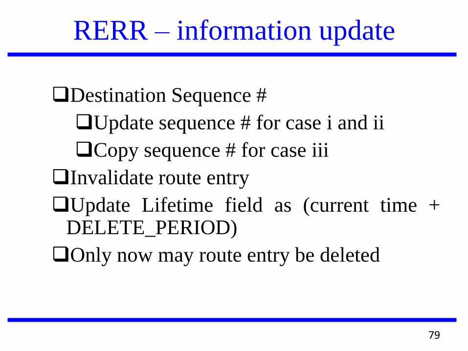
RERR – information update
Destination Sequence #
Update sequence # for case i and ii
Copy sequence # for case iii
Invalidate route entry
Update Lifetime field as (current time + DELETE_PERIOD)
Only now may route entry be deleted
79

RERR message transmission
Unicast
A node detects that a link with adjacent neighbor is broken (destination no longer reachable).
Send RERR to single recipient
If it gets a data packet destined to a node for which it does not have an active route and is not repairing.
If it receives a RERR from a neighbor for one or more active routes.
Unicast iterative
Send RERR to a number of recipients individually
Broadcast
Notify multiple recipients simultaneously
Broadcast via 255.255.255.255 TTL = 1
80

81
A Combined Protocol
It is possible to exploit the good features of both reactive and proactive protcols and the Zone routing protocol does that.
The proactive part of the protocol is restricted to a small neighbourhood of a node and the reactive part is used for routing across the network.
This reduces latency in route discovery and reduces the number of control messages as well.

82
Routing Zones
Each node S in the network has a routing
zone. This is the proactive zone for S as S
collects information about its routing zone in
the manner of the DSDV protocol.
If the radius of the routing zone is k, each node
in the zone can be reached within k hops from
S.
The minimum distance of a peripheral node
from S is k (the radius).

83
A Routing Zone
S
L K
G
H
I
J
A B
C D
E
All nodes except L are in the routing zone of S with radius 2.

84
Nodes in a Routing Zone
The coverage of a node´s trasmitter is the set
of nodes in direct communication with the
node. These are also called neighbours.
In other words, the neighbours of a node are
the nodes which are one hop away.
For S, if the radius of the routing zone is k,
the zone includes all the nodes which are k-
hops away.

85
Neighbour Discovery Protocol
Like other ad hoc routing protocols, each node
executes ZRP to know its current neighbours.
Each node transmits a hello message at regular
intervals to all nodes within its transmission
range.
If a node P does not receive a hello message
from a previously known neighbour Q, P
removes Q from its list of neighbours.

86
Basic Strategy in ZRP
The routing in ZRP is divided into two parts
Intrazone routing : First, the packet is sent within
the routing zone of the source node to reach the
peripheral nodes.
Interzone routing : Then the packet is sent from
the peripheral nodes towards the destination node.
S
D

87
Intrazone Routing
Each node collects information about all
the nodes in its routing zone proactively.
This strategy is similar to a proactive
protocol like DSDV.
Each node maintains a routing table for its
routing zone, so that it can find a route to
any node in the routing zone from this
table.
88
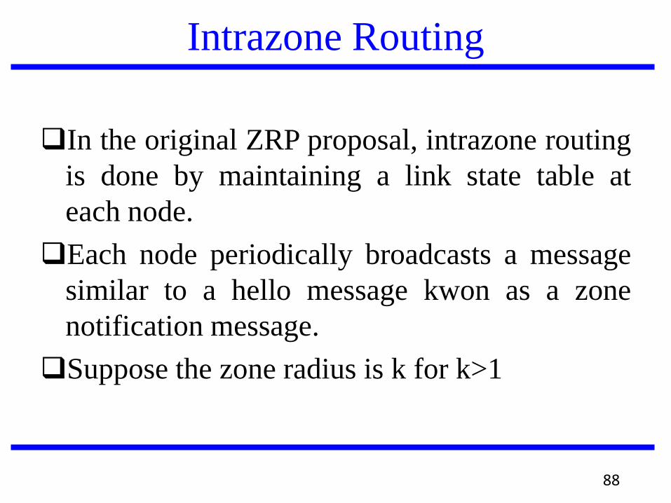
Intrazone Routing
In the original ZRP proposal, intrazone routing
is done by maintaining a link state table at
each node.
Each node periodically broadcasts a message
similar to a hello message kwon as a zone
notification message.
Suppose the zone radius is k for k>1

89
Zone Notification Message
A hello message dies after one hop, i.e., after
reaching a node´s neighbours.
A zone notification mesage dies after k hops,
i.e., after reaching the node´s neighbours at a
distance of k hops.
Each node receiving this message decreases
the hop count of the message by 1 and
forwards the message to its neighbours.

90#
Keeping Track of Nodes in a Routing Zone
The message is not forwarded any more when
the hop count is 0.
Each node P keeps track of its neighbour Q
from whom it received the message through an
entry in its link state table.
P can keep track of all the nodes in its routing
zone through its link state table.

91#
ZRP: Example with Zone Radius K= 2
S C A
E F
B
D
S performs route
discovery for D
Denotes route request

92#
S C A
E
F
B
D
S performs route
discovery for D
Denotes route reply
E knows route from E to D,
so route request need not be
forwarded to D from E
ZRP: Example with Zone Radius K= 2
93#
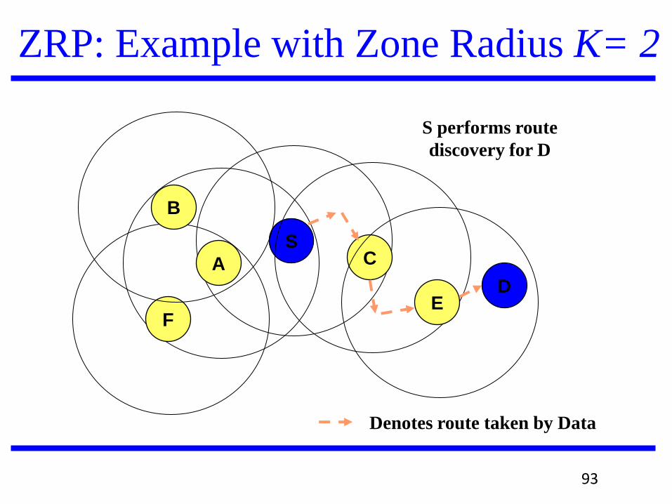
S C A
E F
B
D
S performs route
discovery for D
Denotes route taken by Data
ZRP: Example with Zone Radius K= 2

94#
Interzone Routing
The interzone routing discovers routes to the
destination reactively.
Consider a source (S) and a destination (D).
If D is within the routing zone of S, the
routing is completed in the intrazone routing
phase.
Otherwise, S sends the packet to the
peripheral nodes of its zone through
bordercasting.

95#
Bordercasting
The bordercasting to peripheral nodes can be
done mainly in two ways
By maintaining a multicast tree for the
peripheral nodes. S is the root of this tree.
Otherwise, S maintains complete routing
table for its zone and routes the packet to
the peripheral nodes by consulting this
routing table.

96#
Interzone Route Discovery
S sends a route request (RREQ) message to
the peripheral nodes of its zone through
bordercasting.
Each peripheral node P executes the same
algorithm.
First, P checks whether the destination D is
within its routing zone and if so, sends the
packet to D.
Otherwise, P sends the packet to the peripheral
nodes of its routing zone through bordercasting.

97#
An Example of Interzone Routing
S
D
B
H
A
C

98#
Route Reply in Interzone Routing
If a node P finds that the destination D is
within its routing zone, P can initiate a route
reply.
Each node appends its address to the RREQ
message during the route request phase. This
is similar to route request phase in DSR.
This accumulated address can be used to send
the route reply (RREP) back to the source
node S.

99#
Route Reply in Interzone Routing
An alternative strategy is to keep forward and
backward links at every node´s routing table
similar to the AODV protocol. This helps in
keeping the packet size constant.
A RREQ usually results in more than one
RREP and ZRP keeps track of more than one
path between S and D. An alternative path is
chosen in case one path is broken.

100#
Route Maintenance
When there is a broken link along an active
path between S and D, a local path repair
procedure is initiated.
A broken link is always within the routing
zone of some node.
A
B

101#
Route Maintenance
Hence, repairing a broken link requires
establishing a new path between two nodes
within a routing zone.
The repair is done by the starting node of the
link (node A in the previous diagram) by
sending a route repair message to node B
within its routing zone.
This is like a RREQ message from A with B as
the destination.

102#
How to Prevent Flooding of the Network
Interzone routing may generate many copies of
the same RREQ message if not directed
correctly.
The RREQ should be steered towards the
destination or towards previously unexplored
regions of the network.
Otherwise, the same RREQ message may
reach the same nodes many times, causing the
flooding of the network.

103#
Routing Zones Overlap Heavily
Since each node has its own routing zone,
the routing zones of neighbouring nodes
overlap heavily.
Since each peripheral node of a zone
forwards the RREQ message, the message
can reach the same node multiple times
without proper control.
Each node may forward the same RREQ
multiple times.

Guiding the Search in InterZone Routing
The search explores new regions of the network.
104#

105#
Query Forwarding and Termination Strategy
When a node P receives a RREQ message, P
records the message in its list of RREQ
messages that it has received.
If P receives the same RREQ more than
once, it does not forward the RREQ the
second time onwards.
Also P can keep track of passing RREQ
messages in several different ways.

106#
Termination Strategies
In the promiscuous mode of operation
according to IEEE 802.11 standards, a node
can overhear passing traffic.
Also, a node may act as a routing node
during bordercasting in the intrazone routing
phase.
Whenever P receives a RREQ message
through any of these means, it remembers
which routing zone the message is meant for.

107#
Termination Strategies
Suppose P has a list of nodes A, B,C,...,N such
that the RREQ message has already arrived in
the routing zones of the nodes A, B, C, ...,N.
Now P receives a request to forward a RREQ
message from another node Q.
This may happen when P is a peripheral node
for the routing zone of Q.

108
Early Termination of Unnecessary RREQs
P receives a RREQ from Q since P is a peripheral
node for the routing zone of Q.
P does not bordercast the RREQ to A,B,...,N but
only to X which is not in its list.
P
Q A
B
C
N X

Evaluation of ZRP
When the radius of the routing zone is 1, the
behaviour of ZRP is like a pure reactive
protocol, for example, like DSR.
When the radius of the routing zone is
infinity (or the diameter of the network),
ZRP behaves like a pure proactive protocol,
for example, like DSDV.
The optimal zone radius depends on node
mobility and route query rates.
109

Control Traffic
Control traffic generated by a protocol is the
number of overhead packets generated due to
route discovery requests.
In ZRP, control traffic is generated due to
interzone and intrazone routing.
Hello messages transmitted for neighbour
discovery are not considered as control
traffic since mobility has no effect on it.
110

111#
Control Traffic for Intrazone Routing
In the intrazone routing, each node needs to
construct the bordercast tree for its zone.
With a zone radius of r, this requires
complete exchange of information over a
distance of 2r-1 hops.
For unbounded networks with a uniform
distribution of nodes, this results in O( )
intrazone control traffic.
2r

Control Traffic for Intrazone Routing
However, for a bounded network, the
dependence is lower than
There is no intrazone control traffic when
r=1.
The intrazone control traffic grows fast in
practice with increase in zone radius. So,
it is important to keep the zone radius
small.
2r
112

Control Traffic for Interzone Routing
When the zone radius is 1, the control traffic is
maximum since ZRP degenerates into flood
search.
In other words, every RREQ message
potentially floods the entire network. This is
due to the fact that all the neighbours of a node
n are its peripheral nodes.
However, control traffic drops considerably
even if the zone radius is just 2.
113

Control Traffic for Interzone Routing
The control traffic can be reduced drastically
with early query termination, when a RREQ
message is prevented from going to the same
region of the network multiple times.
However, the amount of control traffic
depends both on node mobility and query rate.
The performance of ZRP is measured by
compairing control traffic with call-to-mobility
(CMR) ratio.
114

Control Traffic for Interzone Routing
The call-to-mobility ratio (CMR) is the ratio of
route query rate to node speed.
As CMR increases, the number of control
messages is reduced by increasing the radius
of the routing zones.
This is because, it is easier to maintain larger
routing zones if mobility is low. Hence, route
discovery traffic also reduces.
115
Control Traffic for Interzone Routing
On the other hand, CMR is low if mobility is
high.
In such a case, the routing zone maintenance
becomes very costly and smaller routing zones
are better for reducing control traffic.
An optimally configured ZRP for a CMR of
500 [query/km] produces 70% less traffic than
flood searching.
116

Route Query Response Time
For a fixed CMR, the route query response
time decreases initially with increased zone
radius.
However, after a certain radius, the response
time increases with zone radius.
This is due to the fact that the network takes
longer time to settle even with small changes
in large routing zones.
117

Expected advantages from multicast
routing
Providing efficient bandwidth
Reducing communication cost
Efficient delivery of data
Supporting dynamic topology
118
Technical constraints for multicast
routing
Minimizing network load
Providing basic support for reliable
transmission
Designing optimal routes
Providing robustness, efficiency, and
adaptability
119

Classification
Globally, there are two main categories of
multicast routing protocols
Tree-based protocols
Mesh-based protocols
120

Examples of tree-based protocols
Multicast Ad hoc On-Demand Distance Vector
(MAODV) routing protocol
Extends AODV to offer multicast capabilities
Builds shared multicast trees on-demand to
connect group members
Capable of unicast, broadcast, and multicast
Associativity based Multicast (ABAM) routing
protocol
Constructed in an attempt to reduce
communication overhead and end-to-end delay
121

An example of mesh-based protocols
On-Demand Multicast Routing Protocol (ODMRP)
ODMRP is based on a mesh structure for connecting
multicast members using the concept of forwarding
group nodes.
When a data packet reaches a multicast receiver, the
receiver creates a Join-Table and broadcasts it to the
neighbors.
Each group member propagates the Join-Table until it
reaches the multicast source via the shortest path.
This process constructs and updates the routes from the
source to the receiver, creating a mesh of nodes.
122

VANETs
A VANET (Vehicular Ad hoc NETwork) is a special kind
of MANET in which packets are exchanged between
mobile nodes (vehicles) traveling on constrained paths
123

Inter-vehicle communication (IVC)
Systems
IVC systems are completely infrastructure-free; only
onboard units (OBUs) sometimes also called in-vehicle
equipment (IVE) are needed.
Single-hop and multi-hop IVCs (SIVCs and MIVCs).
SIVC systems are useful for applications requiring
short-range communications (e.g., lane merging,
automatic cruise control)
MIVC systems are more complex than SIVCs but can
also support applications that require long-range
communications (e.g., traffic monitoring)
124

IVC systems
a) Single-hop IVC system b) multi-hop IVC system
125

Roadside-to-Vehicle Communication
(RVC) Systems
RVC systems assume that all communications
take place between roadside infrastructure
(including roadside units [RSUs]) and OBUs.
Depending on the application, two different
types of infrastructure can be distinguished
Sparse RVC (SRVC) system
Ubiquitous RVC (URVC) system
126

RVC Systems –SRVC
SRVC systems are capable of providing
communication services at hot spots.
A busy intersection scheduling its traffic light, a
gas station advertising its existence (and prices),
and parking availability at an airport, are
examples of applications requiring an SRVC
system.
An SRVC system can be deployed gradually,
thus not requiring substantial investments before
any available benefits.
127

RVC Systems -URVC
A URVC system : providing all roads with
high-speed communication would enable
applications unavailable with any of the other
systems.
Unfortunately, a URVC system may require
considerable investments for providing full
(even significant) coverage of existing
roadways (especially in large countries like
the United States)
128

Hybrid Vehicular Communication
(HVC) Systems
HVC systems are proposed for extending the range of RVC systems.
In HVC systems vehicles communicate with roadside infrastructure even when they are not in direct wireless range by using other vehicles as mobile routers.
An HVC system enables the same applications as an RVC system with a larger transmission range.
The main advantage is that it requires less roadside infrastructure. However, one disadvantage is that network connectivity may not be guaranteed in scenarios with low vehicle density.
129

IVC vs. MANET
MANETs are wireless multihop networks that lack
infrastructure, and are decentralized and self-organizing
IVC systems satisfy all these requirements, and are therefore a
special class of MANETs
There are several characteristics that differentiate IVCs from
the common assumptions made in the MANET literature:
Applications
Addressing
Rate of Link Changes
Mobility Model
Energy Efficiency
130

IVC vs. MANET
Applications
While most MANET articles do not address
specific applications, the common assumption in
MANET literature is that MANET applications are
identical (or similar) to those enabled by the
Internet.
In contrast, as we show later, IVCs have
completely different applications. An important
consequence of the difference in the applications is
the difference in the addressing modes.
131

IVC vs. MANET
Addressing
Faithful to the Internet model, MANET applications
require point-to-point (unicast) with fixed addressing;
that is, the recipient of a message is another node in the
network specified by its IP address.
IVC applications often require dissemination of the
messages to many nodes (multicast) that satisfy some
geographical constraints and possibly other criteria
(e.g., direction of movement). The need for this
addressing mode requires a significantly different
routing paradigm.
132
IVC vs. MANET
Rate of Link Changes
In MANETs, the nodes are assumed to have moderate mobility. This assumption allows MANET routing protocols (e.g., Ad Hoc On Demand Distance Vector, AODV) to establish end-to-end paths that are valid for a reasonable amount of time and only occasionally need repairs.
In IVC applications, it is shown that due to the high degree of mobility of the nodes involved, even multi-hop paths that only use nodes moving in the same direction on a highway have a lifetime comparable to the time needed to discover the path.
133

IVC vs. MANET
Mobility Model
In MANETs, the random waypoint (RWP) is (by far) the most commonly employed mobility model. However, for IVC systems, most existing literature recognized that RWP would be a very poor approximation of real vehicular mobility; instead, detailed vehicular traffic simulators are used.
Energy Efficiency
While in MANETs a significant body of literature is concerned with power-efficient protocols, IVC enjoys a practically unlimited power supply.
134

VANETs
Like MANETs:
They self-organize over an evolving topology
They may rely on multi-hop communications
They can work without the support of a fixed
infrastructure
Unlike MANETs:
They have been conceived for a different set of
applications
They move at higher speeds (0-40 m/s)
They do not have battery and storage constraints
135

VANETs
Communication modes:
Vehicle-to-Vehicle (V2V) among vehicles
Vehicle-to-Infrastructure (V2I), between vehicles and
Road-Side Units (RSUs)
Vehicle-to-X (V2X), mixed V2V-V2I approach
V2V
V2I
V2V
V2I
RSU
RSU
136

VANETs Applications Active Road-Safety Applications
To avoid the risk of car accidents: e.g., cooperative collision
warning, pre-crash sensing, lane change, traffic violation
warning
Traffic efficiency and management applications
To optimize flows of vehicles: e.g., enhanced route
guidance/navigation, traffic light optimal scheduling, lane
merging assistance
Comfort and Infotainment applications
To provide the driver with information support and
entertainment: e.g., point of interest notification, media
downloading, map download and update, parking access,
media streaming, voice over IP, multiplayer gaming, web
browsing, social networking
137

VANETs
VANETs applications exhibit very
heterogeneous requirements
Safety applications require reliable, low-latency,
and efficient message dissemination
Non-safety applications have very different
communication requirements, from no special
real-time requirements of traveler information
support applications, to guaranteed Quality-of-
Service needs of multimedia and interactive
entertainment applications
138

Connectivity in VANETs
There are three primary models for
interconnecting vehicles based on
Network infrastructure
Inter-vehicle communications
Hybrid configuration
139

Connectivity in VANETs
Network infrastructure
Vehicles connect to a centralized server or a backbone
network such as the Internet, through the road-side
infrastructure, e.g., cellular base stations, IEEE 802.11
Access Points, IEEE 802.11p RSUs
140

Connectivity in VANETs
Inter-vehicle communications
Use of direct ad-hoc connectivity among vehicles via
multihop for applications requiring long-range
communications (e.g., traffic monitoring), as well as
short-range communications (e.g., lane merging)
141

Connectivity in VANETs
Hybrid configuration
Use of a combination of V2V and V2I. Vehicles in
range directly connect to the road-side infrastructure,
while exploit multi-hop connectivity otherwise
142

Connectivity in VANETs
Vehicles’ connectivity is determined by a
combination of several factors, like:
Space and time dynamics of moving vehicles
(i.e., vehicle density and speed)
Density of RSUs
Radio communication range
Connectivity Communication range
RSU
Vehicular scenario • Urban • Highway
Market penetration
Vehicle density/speed
Time of day
143

Improving Connectivity in VANETs
• Opportunistic approaches for connectivity
support in VANETs
– Opportunistic contacts, both among vehicles and from
vehicles to available RSUs, can be used to instantiate
and sustain both safety and non-safety applications
• Opportunistic forwarding is the main technique
adopted in DTN
– In VANETs, bridging technique links the
partitioning that exists between clusters traveling in
the same direction of the roadway
144

Improving Connectivity in VANETs
The use of a vehicular grid together with an
opportunistic infrastructure placed on the roads
guarantees seamless connectivity in dynamic
vehicular scenarios
Hybrid communication paradigms for vehicular
networking are used to limit intermittent connectivity
Vehicle-to-X (V2X) works in heterogeneous
scenarios, where overlapping wireless networks
partially cover the vehicular grid. It relies on the
concept of multi-hop communication path
145

Improving Connectivity in VANETs
Different connectivity phases
Phase 1 (No connectivity)
A vehicle is traveling alone in the vehicular grid (totally-
disconnected traffic scenario). The vehicles are completely
disconnected
Phase 2 (Short-range connectivity)
A vehicle is traveling in the vehicular grid and forming a
cluster with other vehicles. Only V2V connectivity is
available
Phase 3 (Long-range connectivity)
A vehicle is traveling in the vehicular grid with available
neighboring RSUs. Only V2I connectivity is assumed to be
available
146

Examples
147#

Applications for VANETs
Public Safety Applications
Traffic Management Applications
Traffic Coordination and Assistance Applications
Traveller Information Support Applications
Comfort Applications
Air pollution emission measurement and reduction
Law enforcement
Broadband services
148

Problems in MANET
Routing
Security and Reliability
Quality of Service
Internetworking
Power Consumption
149

SECURITY
A major issue in Mobile ad-hoc network is “SECURITY”.
Two approaches in protecting mobile ad-hoc networks
Reactive approach: Seeks to detect security threats and react accordingly.
Proactive approach: Attempts to prevent an attacker from launching attacks through various cryptographic techniques.
150
Issues
Secure Multicasting
Secure routing
Privacy-aware Routing
Key management
Intrusion detection System
151

Issues Contd.. Secure multicasting: Is a communication method where
a single data packet can be transmitted from a sender and
replicated to a set of receivers.
Secure routing: Most MANET routing protocols are
vulnerable to attacks that can freeze the whole network.
Need some solutions that work even if some nodes
compromised.
Privacy-aware Routing: Building routing protocols that prevent intermediate nodes from performing traffic analysis.
Schemes for minimizing size of crypto-tags( digital signatures) are needed.
152

Issues Contd..
Key Management
security goals in MANET are mainly achieved through trusted Certificate Authority (CA)
compromised CA can easily damage the entire network.
Intrusion detection and response schemes: Anomaly detection is difficult in MANETs (ex: types of attacks and their source). collaborative IDS schemes are needed.
153

Security Goals
Authentication
Confidentiality
Integrity
Non-repudiation
Availability
Detection and Isolation
154

Authentication: A node must know the identity of the peer node it
is communicating with. Without authentication, an attacker could
gain sensitive information and interfere with other nodes
Confidentiality: Ensures certain information is never disclosed to
unauthorized entities.
Integrity: Message being transmitted is never corrupted.
Non-Repudiation: The sender cannot later deny sending the information and the receiver cannot deny the reception.
Availability: Nodes should be available for communication at all times. A node need continue to provide services despite attacks.
E.g.: Key management service.
Detection and Isolation: Require the protocol can identify misbehaving nodes and render them unable to interfere with routing.
Security Goals
155

IDS-MANET
IDS: Intrusion detection System which is used to detect and report the malicious activity in ad hoc networks.
Ex: Detecting critical nodes using IDS
Intrusion Detection System (IDS) can collect and analyze audit data for the entire network.
Critical node is a node whose failure or malicious behavior disconnects or significantly degrades the performance of the network.
Packets may be dropped due to network congestion or because a malicious node is not faithfully executing a routing algorithm.
Researchers have proposed a number of collaborative IDS systems.
Some of the schemes are neighbor-monitoring, trust-building, and cluster-based voting schemes which are used to detect and report the malicious activity in ad hoc networks.
156

Questions ?
157