ISSN 1402-1544 Stability of Low-Frequency AC Railways
104
Stability of Low-Frequency AC Railways Models and Transient Stability John Laury Electric Power Engineering DOCTORAL THESIS
Transcript of ISSN 1402-1544 Stability of Low-Frequency AC Railways
Stability of Low-Frequency AC RailwaysModels and Transient Stability
John Laury
Electric Power Engineering
Department of Engineering Sciences and MathematicsDivision of Energy Science
ISSN 1402-1544ISBN 978-91-7790-292-8 (print)ISBN 978-91-7790-293-5 (pdf)
Luleå University of Technology 2019
DOCTORA L T H E S I S
John Laury Stability of Low-Frequency A
C R
ailways - M
odels and Transient Stability
Stability of Low-Frequency AC Railways
Models and Transient Stability
John Laury
Luleå University of TechnologyDepartment of Engineering Sciences and Mathematics
Division of Energy Science

Printed by Luleå University of Technology, Graphic Production 2019
ISSN 1402-1544 ISBN 978-91-7790-292-8 (print)ISBN 978-91-7790-293-5 (pdf)
Luleå 2019
www.ltu.se
Abstract
Low-frequency AC railway grids are unique in the sense that a only few coun-tries around the world uses them, still however, they are an important partsof their countries infrastructures. Due to the usage of a different frequencythan the public grid of the country, conversion of frequency is needed for theinterconnection. The frequency conversion is done by machine based rotaryfrequency converters or power electronic based static frequency converters.
When reinforcing with new power conversion capacity, mostly static fre-quency converters are installed since rotary frequency converters for railwayshave not been manufactured for some time. As more static frequency con-verter are introduced, the share of rotary frequency converters is reduced. Itis not well explored how the stability of low-frequency AC railways is affectedwith a large share of static frequency converters.
In this thesis, the main goal has been to obtain knowledge of the stabilityof low-frequency AC railway grids, with focus on synchronous ones. The elec-tromechanical stability of a synchronous low-frequency AC railway is exploredthrough numerical simulations, where the transient stability is the main focus.
The main contributions of this thesis is proposing a model of a rotaryfrequency converter, proposing a model of a static frequency converter, andtransient stability simulations. The model of the rotary frequency converteruses established machine models, whereas the static frequency converter modelhas been developed with help of measurements. It can be concluded that theproposed static frequency converter model captures the main behaviour of themeasurements of a static frequency converter.
The transient stability of synchronous AC railway grids is studied, throughnumerical simulations. The studied cases are for instance different railway gridconfigurations with different types rotary frequency converters and railwaygrids with mixes of static frequency converters and static frequency converter.
The main conclusion is that the rotary frequency converter fed synchronous
i

ii
railway grids studied are transiently stable, and the studied railway gridswhere rotary frequency converters are gradually replaced with static frequencyconverter are also transiently stable. However, it was found that the studiedrailway grids obtain a heavier oscillatory behaviour when there is a mix ofrotary frequency converters and static frequency converters.
Sammanfattning
Lagfrekventa jarnvagsnat ar unika i den meningen att fa lander runt om ivarlden anvander dem, men for de lander som anvander lagfrekventa jarnvags-nat ar det en viktig del av deras infrastrukturen. Pa grund av anvandningenav andra frekvenser an det offentliga natet kravs omvandling av frekvensfor anslutning. Frekvensomvandlingen sker med maskinbaserade roterandefrekvensomformare eller effektelektroniska frekvensomrikatare.
Vid forstarkning med ny omvandlings-kapacitet av effekt, installeras mes-tadels effektelektroniska frekvensomriktare da inga nya maskinbaserade rote-rande omformare fo har producerats for jarnvag. Nar mera effektelektroniskafrekvensomriktare introduceras, sjunker andelen av maskinbaserade roternadefrekvensomformare. Det ar inte val studerat hur stabiliteten i lagfrekventajarnvagsnat paverkas med en okande andelar effektelektroniska frekvensom-riktare.
I denna avhandling har huvudmalet varit att fa kunskap om stabilitetenhos lagfrekvent jarnvagsnat, med fokus pa det synkrona sadana. Den elek-tromekaniska stabiliteten hos synkrona lagfrekventa jarnvagsnatet utforskasgenom numeriska simuleringar, dar den transienta stabiliteten ar huvudfokus.
Huvudbidragen fran denna avhandling ar en foreslagen modell for en mask-inbaserad frekvensomformare, en forslagen modell av en effektelektronisk frek-vensomriktare och simuleringar av den transient stabilitet. Modellen forden maskinbaserad frekvensomformare anvander etablerade maskinmodeller,medans den effektelektroniska frekvensomrikatar modellen har tagits frammed hjalp av matningar. Man kan dra slutsatsen att den foreslagna mod-ellen av en effektelektronisk frekvensomriktare fangar det huvudbeteendet hosmatningarna av en effektelektronisk frekvensomriktare.
De transienta stabilitets-simuleringarna studerar flera fall med olika kon-figurationer av jarnvagsnat med olika typer av maskinbaserade roternadefrekvensomformare, samt blandningen av effektelektroniska frekvensomriktare
iii

iv
och maskinbaserade roternade frekvensomformare.Huvudslutsatsen ar att de studerade synkrona jarnvagsnaten matade med
roterande frekvensomformare ar transient stabila, och de studerade jarnvags-nat dar roterande frekvenskomformare gradvis byts ut mot effektelektron-iska frekvensomriktare ar ocksa transient stabila. Dock far de studeradejarnvagsnat med roterande frekvenskomformare och effektelektroniska frekven-somriktare en mer oscillativt beetende.
Acknowledgements
I want to thanks my main supervisor Professor Math Bollen for allowing meto do research in low-frequency AC railways.
I also want thank the reference group members of this project: Mats Hager,Anders Bulund, David Ribbenfjard and Alija Cosic from the Swedish Trans-port Administration, and Magnus Olofsson for their inputs at the referencegroup meetings. A special thanks to Professor Stefan Ostlund, Dr. ThorstenSchutte and Dr. Steinar Danielsen for answering railway specific questions.
I want to especially thank my co-supervisor, Dr. Lars Abrahamsson for hissupport, interest in the subject, the interesting discussions, taking time fordeep explanation and guidance during this thesis.
A special thanks to Dr. Martin Lundmark, Dr. Anders Larsson and Profes-sor Marcus Ohman for their support during this Ph.D project and especiallyin the end.
I also want to thanks my colleagues in the Electrical Power EngineeringGroup in Skelleftea for the good laughs and the very interesting discussions. Aspecial thanks Benedikt Neyses from wood-technology for the nice discussionsabout everything and the laughs inside and outside university. Also a specialthank to my ex-colleague Dr. Gaurav Singh for the late night discussionsand laughs inside and outside work, during his stay in the Electrical PowerEngineering Group in Skelleftea.
Finally, I want to especially thank my wonderful fiance Anu Tiilikainen forher never ending love, patience and support during this time. Thank you mylove for giving me one of the greatest joys of my life, my daughter and a soonto be born son.
Even if you are not here mother, you are watching from heaven, thanksfor raising me to be the man I am today.
John LauryFebruary, 2019
v

vi
Table of Contents
Abstract i
Sammanfattning iii
Acknowledgements v
1 Introduction 11.1 Background . . . . . . . . . . . . . . . . . . . . . . . . . . . . . 11.2 Motivation . . . . . . . . . . . . . . . . . . . . . . . . . . . . . 31.3 Scope . . . . . . . . . . . . . . . . . . . . . . . . . . . . . . . . 31.4 Approach . . . . . . . . . . . . . . . . . . . . . . . . . . . . . . 41.5 Contributions . . . . . . . . . . . . . . . . . . . . . . . . . . . . 51.6 Structure of the thesis . . . . . . . . . . . . . . . . . . . . . . . 51.7 Publications originating from this thesis . . . . . . . . . . . . . 61.8 Other contributions from the author . . . . . . . . . . . . . . . 8
I Introduction of the Thesis 9
2 Low-frequency AC railways 112.1 Brief historical overview of electrified railways . . . . . . . . . . 112.2 A brief introduction to the Swedish electrified railway grid . . . 122.3 Catenary systems . . . . . . . . . . . . . . . . . . . . . . . . . . 13
2.3.1 BT Systems . . . . . . . . . . . . . . . . . . . . . . . . . 132.3.2 AT Systems . . . . . . . . . . . . . . . . . . . . . . . . . 14
2.4 High voltage transmission systems . . . . . . . . . . . . . . . . 142.5 Frequency converters . . . . . . . . . . . . . . . . . . . . . . . . 15
2.5.1 Rotary Frequency Converters . . . . . . . . . . . . . . . 152.5.1.1 Synchronous-Synchronous RFC . . . . . . . . . 15
vii
viii TABLE OF CONTENTS
2.5.1.2 Asynchronous-Synchronous RFC . . . . . . . . 162.5.2 Static Frequency Converters . . . . . . . . . . . . . . . . 17
2.5.2.1 Direct converters (Cyclo-converters) . . . . . . 172.5.2.2 DC-link converters . . . . . . . . . . . . . . . . 172.5.2.3 MMC converters . . . . . . . . . . . . . . . . . 18
2.6 Synchronous and Asynchronous railway grids . . . . . . . . . . 18
3 Power System Stability Definitions and Classifications 213.1 Definitions . . . . . . . . . . . . . . . . . . . . . . . . . . . . . . 213.2 Classifications . . . . . . . . . . . . . . . . . . . . . . . . . . . . 22
3.2.1 Rotor Angle Stability . . . . . . . . . . . . . . . . . . . 223.2.2 Voltage Stability . . . . . . . . . . . . . . . . . . . . . . 233.2.3 Frequency Stability . . . . . . . . . . . . . . . . . . . . . 24
4 Stability in Railway Power Systems 254.1 Rotor Angle Stability . . . . . . . . . . . . . . . . . . . . . . . 25
4.1.1 Transient Stability . . . . . . . . . . . . . . . . . . . . . 254.1.2 Small-signal Stability . . . . . . . . . . . . . . . . . . . 26
4.1.2.1 Low-frequency oscillations in 16 23 Hz railways . 26
4.1.2.2 Low-frequency oscillations in 50 Hz railways . 264.2 Voltage Stability . . . . . . . . . . . . . . . . . . . . . . . . . . 274.3 Frequency Stability . . . . . . . . . . . . . . . . . . . . . . . . . 27
4.3.1 Low-frequency AC railways . . . . . . . . . . . . . . . . 274.3.2 Frequency stability in transformer fed 50 Hz railways . . 28
5 Mathematical model of a power system 295.1 Mathematical model . . . . . . . . . . . . . . . . . . . . . . . . 295.2 Phasors . . . . . . . . . . . . . . . . . . . . . . . . . . . . . . . 305.3 Transformation between frames . . . . . . . . . . . . . . . . . . 325.4 Overall modelling assumptions . . . . . . . . . . . . . . . . . . 32
II Results of the Thesis 35
6 Models developed 376.1 Proposed RFC model, Paper I . . . . . . . . . . . . . . . . . . 37
6.1.1 Summary . . . . . . . . . . . . . . . . . . . . . . . . . . 376.1.2 Modelling discussion . . . . . . . . . . . . . . . . . . . . 38
6.1.2.1 Single-phase machine as a three-phase machine 386.1.2.2 Stator transients . . . . . . . . . . . . . . . . . 38
TABLE OF CONTENTS ix
6.1.2.3 Sub-transient saliency . . . . . . . . . . . . . . 396.2 Proposed SFC model, Paper II . . . . . . . . . . . . . . . . . . 39
6.2.1 Summary . . . . . . . . . . . . . . . . . . . . . . . . . . 39
7 Transient stability studies 417.1 RFC-fed railway grids . . . . . . . . . . . . . . . . . . . . . . . 417.2 Replacing RFCs with SFCs . . . . . . . . . . . . . . . . . . . . 427.3 Impact of load models in a RFC-fed railway . . . . . . . . . . . 427.4 Brief summary of Paper VIII . . . . . . . . . . . . . . . . . . . 43
III Conclusions of the Thesis 45
8 Conclusions 478.1 Models developed were needed . . . . . . . . . . . . . . . . . . 478.2 The RFC model . . . . . . . . . . . . . . . . . . . . . . . . . . 478.3 The SFC model . . . . . . . . . . . . . . . . . . . . . . . . . . . 488.4 Conclusions from numerical simulations . . . . . . . . . . . . . 48
9 Discussions 499.1 Three-phase grid impact . . . . . . . . . . . . . . . . . . . . . . 499.2 Different converter types . . . . . . . . . . . . . . . . . . . . . . 49
9.2.1 Different RFC types behaviour . . . . . . . . . . . . . . 499.2.2 Different RFC types as well as RFCs and SFCs operat-
ing together . . . . . . . . . . . . . . . . . . . . . . . . . 509.2.2.1 Different RFC types . . . . . . . . . . . . . . . 509.2.2.2 RFCs and SFCs operating together . . . . . . 50
9.2.3 Larger and meshed test systems . . . . . . . . . . . . . 509.3 RFC modelling . . . . . . . . . . . . . . . . . . . . . . . . . . . 50
9.3.1 Sub-transient saliency . . . . . . . . . . . . . . . . . . . 509.3.2 Validity of model parameters . . . . . . . . . . . . . . . 519.3.3 Excitation systems . . . . . . . . . . . . . . . . . . . . . 51
9.4 SFC modelling . . . . . . . . . . . . . . . . . . . . . . . . . . . 519.4.1 DC-link and rectifier . . . . . . . . . . . . . . . . . . . . 519.4.2 Non-regenerating SFCs . . . . . . . . . . . . . . . . . . 529.4.3 Current limitation modes . . . . . . . . . . . . . . . . . 529.4.4 Decreased oscillations with 100% SFCs . . . . . . . . . . 539.4.5 Location and distribution of converters . . . . . . . . . 53
9.5 Train models . . . . . . . . . . . . . . . . . . . . . . . . . . . . 549.6 System loading . . . . . . . . . . . . . . . . . . . . . . . . . . . 54
x TABLE OF CONTENTS
9.7 Electromagnetic transient (EMT) simulations . . . . . . . . . . 54
10 Recommendations 5710.1 General recommendations . . . . . . . . . . . . . . . . . . . . . 5710.2 Model recommendations . . . . . . . . . . . . . . . . . . . . . . 58
10.2.1 RFC model . . . . . . . . . . . . . . . . . . . . . . . . . 5810.2.2 SFC model . . . . . . . . . . . . . . . . . . . . . . . . . 5810.2.3 Train model . . . . . . . . . . . . . . . . . . . . . . . . . 59
10.3 Simulation recommendations . . . . . . . . . . . . . . . . . . . 5910.4 Finals Words . . . . . . . . . . . . . . . . . . . . . . . . . . . . 60
References 61
Appendix A RFC Parameters 71
IV Publications 73
Paper I 75
Paper II 87
Paper III 105
Paper IV 117
Paper V 129
Paper VI 141
Paper VII 155
Paper VIII 167
Chapter 1
Introduction
1.1 Background
Electrified AC railways are the most efficient land based mean of transport[1]. It is more environmentally friendly if the supplied energy is CO2 free.Furthermore, electric operation of trains is always preferred as it has greaterefficiency than diesel locomotives [2].
In many countries the railway grid is an important part of the infrastruc-ture and large amounts of capital is invested and tied to the railway grids.
For practical reasons the vast majority of electrified railway grids aresingle-phase, and due to historical and technical reasons there are severaltypes of single-phase railway grids. Most of the railway grids are 50/60 Hz orDC, whereas low-frequency AC railway grids of 16 2
3 Hz, 16.7 Hz and 25 Hzare less common around the world.
There are two types of low-frequency AC railway grids in use. These are thesynchronous1 and the asynchronous2 railway grids, and it is a clear differencein the power supply system operation and control. For further details seeChapter 2.
For railway grids with a different frequency than the public grid frequency,there are two typical main options of converting the three-phase power tosingle-phase power. These options are
• The use of Rotary Frequency Converters (RFCs)
1See Sections 2.5 and 2.6.2See Sections 2.5 and 2.6.
1
2 CHAPTER 1. INTRODUCTION
• The use of Static Frequency Converters (SFCs).
The RFC, which is essentially a motor-generator set, is a three-phase motorand a single-phase generator mounted on the same mechanical shaft. Thelast manufactured synchronous-synchronous RFC3, for the Swedish TransportAdministration4 was delivered in 1978 by ASEA [3], and until the 1990s RFCsstood for the major share of conversion capacity in the Swedish Railway grid.
The first SFC was introduced approximately in the beginning of 1970s [4,5],and all new installations of conversion capacity are from SFCs nowadays. Thismeans that new converter stations will only have SFCs installed unless RFCsare moved from other converter stations, whereas existent converter stationscan have a mix of RFCs and SFCs of different types operating in parallel.
In 2017/2018 the Swedish Transport Administration bought a numbersRFCs of they type Q50 from Deutsche Bahn (DB) to reinforce the SwedishRailway grid with more RFC conversion capacity [6], as the Swedish TransportAdministration noted problems with increased shares of SFCs.
One of the main benefits of SFCs over RFCs is that they are cheaper andmore efficient. Furthermore, modern types of SFCs provide more controlla-bility than RFCs. Thus, a system of consisting only of SFCs would be moreflexible. However, for the Scandinavian low-frequency AC railway the con-trollability is limited due to the topology of the railway grid and the types ofRFCs used, see Chapter 2 for further details.
The main benefit of an RFC over an SFC is that an RFC provides rota-tional inertia and large over-current ability, which may help to stabilize thesystem after a disturbance. Fault detection is easier with an RFC comparedto an SFC, as an SFC enter current limitation mode. An RFC can temporallybe overloaded above its rated power, whereas an SFC enters power limitationmode if the load exceeds the rated power of the SFC.
For the Swedish Transport Administration it is of interest that their electri-cal railway grid is stable. Having a robust and reliable power supply systemavoids unnecessary disconnections of catenary sections, generation, HV-T5
and trains. Available power supply system decreases the risk for train delayminutes, cancelled trains and the related economic costs.
3See Section 2.5.4The Swedish railway grid owner and grid operator. Please do not confuse the grid
operator with the train/transport operator.5See Section 2.4.
1.2. MOTIVATION 3
1.2 Motivation
In 2013, SFCs stood for 60% of the total amount of installed power conversioncapacity in the Swedish railway grid. The share of power conversion capacityfrom SFCs has increased and is expected to increase and continue to do so asthe railway traffic increases. The Swedish Transport Administration has ex-perienced instability in some converter stations, and the hypothesis has beenthat an increased share of SFCs is causing instabilities. Two examples of theexperienced instabilities can be seen in Paper VIII. The Swedish TransportAdministration initiated this project then to investigate the stability of syn-chronous6 railway grids with increased shares of SFCs, and the possible causesof the instabilities experienced can be.
How an RFC-fed synchronous railway grid, like the Swedish one, behaveafter large disturbance has not been well explored in the academic literature.Studies of the behaviour with different types of RFCs that are different in sizeand rating, increases the understanding of the dynamical behaviour of RFC-fed synchronous railway grids. Furthermore, studies of how mixed RFC/SFC-fed synchronous railways grid behaves dynamically after a large disturbancehas not been studied.
There are few commercial software, such as Simpow [7], that have RFCand SFC models, however those model are not accessible for public use. Forinstance, Simpow’s RFC model are unfortunately not fully explained in thesoftware documentation. Therefore, the motivation has been develop an RFCmodel and an SFC model that is more easier accessible, and that can be usedfor electromechanical stability studies.
Published material and research on synchronous railway grids is scarcecompared to three-phase power systems. Therefore it has been motivated tokeep the overall modelling approach as uncomplicated as possible.
1.3 Scope
The overall scope of this thesis has been to obtain knowledge on the stabil-ity of the synchronous railway grid, where the share of RFCs is kept con-stant/reduced for different shares of SFCs; and obtain understating of thesystem behaviour with different types of synchronous-synchronous RFCs.
Suitable open dynamical models of synchronous-synchronous RFCs andSFCs have not been available in the literature. Therefore, large part of thisthesis emphasizes on the development of RFC and SFC models needed for
6See Chapter 2.
4 CHAPTER 1. INTRODUCTION
electromechanical stability7 studies in the phasor domain done in this the-sis. Many of the SFCs used in Sweden cannot cope with regenerative power,see Section 2.5.2. However, the modelling of SFCs that cannot cope withregenerative power is out of the scope of this thesis.
The stability of a synchronous railway grid after a large disturbance is ofinterest. Therefore, the scope has been to study the transient stability andstudy how is impacted by increased shares of SFCs, different RFC types andusing SFCs and RFCs together in the same system. The studies has beenlimited to the RFCs types Q48/Q49 and Q38/Q39, and to a voltage sourceconverter based SFC.
Transient stability of asynchronous low-frequency railway grids are out ofthe scope of this thesis. Also protection system of low-frequency railway gridsand vehicle modelling is also out of the scope of this thesis.
1.4 Approach
The approach has been to use phasors, i.e the Quasi Steady-State8 (QSS)modelling approach, to describe synchronous low-frequency railway grid, andapplying power system analysis tools as presented in literature such as [8–12].
Based on the mentioned literature and in line with the small number ofelectromechanical studies9 available on low-frequency railway grids, an elec-tromechanical RFC model for studies in the phasor domain is developed fortransient stability studies in the phasor domain.
Most SFCs in use in the Swedish synchronous railway grid are based onVoltage Source Converter (VSC) technology. Therefore the approach has beento develop a VSC-SFC model with current limitation, that is able to capturethe electromechanical dynamics at the railway grid side. Measured data atthe railway grid side of an VSC-SFC has been used in the developing of theSFC model. The fast dynamics of the SFC, such as fast acting controllers arenot including in the modelling approach used.
Based on the RFC and SFC models developed in this thesis, computer sim-ulations on simplified synchronous low-frequency railway grids are performedto study the transient stability, and observe the behaviour of and interactionsbetween RFCs and SFCs, or different types of RFCs.
7See Chapter 5.8Also called Quasi-stationary, see Chapter 5.9See Chapter 4 for an overview of the literature on stability in low-frequency railways.
1.5. CONTRIBUTIONS 5
1.5 Contributions
The main contributions of this thesis are:
• An 8:th order RFC model for electromechanical stability studies of syn-chronous railway grids of the type used in Scandinavia has been pro-posed. Using a high-order model of synchronous machines, the dampinghas not be approximated as when using lower order synchronous ma-chine models.
Paper I and Chapter 6
• An SFC model, with current limitation, that reproduces measurements,for electromechanical stability studied of synchronous railway grids ofthe type used in Scandinavia has been proposed.
Paper II and Chapter 6
• Transient stability simulations, where the following have been studied:
– Studies with different types of RFCs in parallel operation, and theimpact of the catenary systems and the HV-T on transient stability.
– Studies of transient stability with no-load and with loads with dif-ferent types of RFCs.
– The impact of gradually replacing RFCs with SFCs in a synchronousrailway grid.
Paper III-VI and Chapter 7
• An effort to present a more comprehensive description of the differencesbetween synchronous and the asynchronous low-frequency railway grids.One that is more accessible to the reader. The differences between thesynchronous and the asynchronous low-frequency railway grid has beenbriefly described in [13,14].
Paper VIII and Chapter 2
1.6 Structure of the thesis
The reminder of this thesis is divided into nine chapters. These chapters are:
• Part I
6 CHAPTER 1. INTRODUCTION
– Chapter 2 gives a fundamental description of the low-frequency ACrailway grids and the differences between synchronous and asyn-chronous railway grids.
– Chapter 3 gives a description of the power system stability clas-sifications that are used for classifying the instabilities that arecalculated or observed.
– Chapter 4 present a literature review of the work done in the fieldof stability in AC railways.
– Chapter 5 presents an overview of the mathematical descriptionsand a foundation that the models in this thesis are based on.
• Part II
– Chapter 6 describes the models of RFCs and SFCs developed andproposed in this thesis.
– Chapter 7 summarizes the results of the transient stability simula-tions done with the models developed.
• Part III
– Chapter 8 presents the overall conclusions of this thesis.
– Chapter 9 discusses the results and different aspect regarding sim-ulations and modelling of RFC, SFC and trains.
– Chapter 10 proposes recommendations for future work.
• Part IV
– Papers I-VIII
1.7 Publications originating from this thesis
The following papers are appended in this thesis:
Paper I: A rotary frequency converter model for electromechanical transientstudies of 16 2
3 Hz railway systems. John Laury, Lars Abrahamsson, MathH.J Bollen. International Journal of Electrical Power and Energy Systems,2019, Volume 106.
1.7. PUBLICATIONS ORIGINATING FROM THIS THESIS 7
Paper II: A simplified static frequency converter model for electromechanicaltransient stability studies of 16 2
3 Hz railways. John Laury, Lars Abrahams-son, Math H.J Bollen. To be submitted.
Paper III: Transient stability of rotary frequency converter fed low-frequencyrailway grids: The impact of different grid impedances and different converterstations configurations. John Laury, Lars Abrahamsson, Math H.J Bollen.Proceedings of the 2018 IEEE/ASME Joint Rail Conference.
Paper IV: Transient stability of a rotary frequency converter fed railway,interconnected with a parallel low-frequency high voltage transmission system.John Laury, Lars Abrahamsson, Math H.J Bollen. Comprail Conference2018, WIT Transactions on The Built Environment, vol 181, 2018.
Paper V: Impact of reduced share of rotary frequency converter in a low-frequency synchronous railway grid: A transient stability study. John Laury,Lars Abrahamsson, Math H.J Bollen. Proceedings of 2019 IEEE/ASME JoinRail Conference.
Paper VI: Further studies of the transient stability of rotary frequency con-verter fed low frequency AC railway with a high voltage transmission., LarsAbrahamsson, John Laury, Math H.J Bollen. Accepted for publishing inInternational Journal of Energy Production and Management, WIT Press.
Paper VII: Evaluating a constant-current load model through comparativetransient stability case studies of a synchronous-synchronous rotary frequencyconverter fed railway., Lars Abrahamsson, John Laury, Math H.J Bollen.Proceedings of 2019 IEEE/ASME Join Rail Conference.
Paper VIII: Challenges with increased share of power electronic generationin railway power supply systems. John Laury, Lars Abrahamsson, Math H.JBollen. Submitted 2017 to Elsevier Electricity Journal.
Other Publications
Improved voltage control in low frequency AC railways. John Laury, LarsAbrahamsson, Math H.J Bollen. Proceedings of the 2017 IEEE/ASME JointRail Conference.
AC cables strengthening railway low frequency AC power supply systems. LarsAbrahamsson, Daniel Jimenez Serrano, John Laury, Math H.J Bollen. Pro-ceedings of the 2017 IEEE/ASME Joint Rail Conference.
8 CHAPTER 1. INTRODUCTION
Division of work between authors
Papers I-V and VIII J. Laury formulated the outline, researched andwrote the papers under guidance and supervision of Dr. L. Abrahamsson.Professor M. Bollen supervised.
Papers VI-VII J. Laury and L. Abrahamsson formulated the outline ofthe papers and worked jointly on the model development. J. Laury did casestudies and simulations. Dr. L. Abrahamsson did the writing of the papers.Professor M. Bollen supervised.
1.8 Other contributions from the author
The author has been a member of the scientific committee of Comprail 2018in Lisbon, Portugal.
Part I
Introduction of the Thesis
9

Chapter 2
Low-frequency AC railways
The aim of this chapter is to provide an introduction to low-frequency ACrailway grids.
2.1 Brief historical overview of electrified rail-ways
The first example of electrified railways was a DC railway in 1879 [5, 14, 15].However around 1890 the advantages of AC over DC became obvious for mainline electric railway operation [5]. However, three-phase electrified railwaygrids had many drawbacks, specially regarding the design of overhead linesand control of the traction motor [5, 16]. Thus, the choice was to use single-phase AC system.
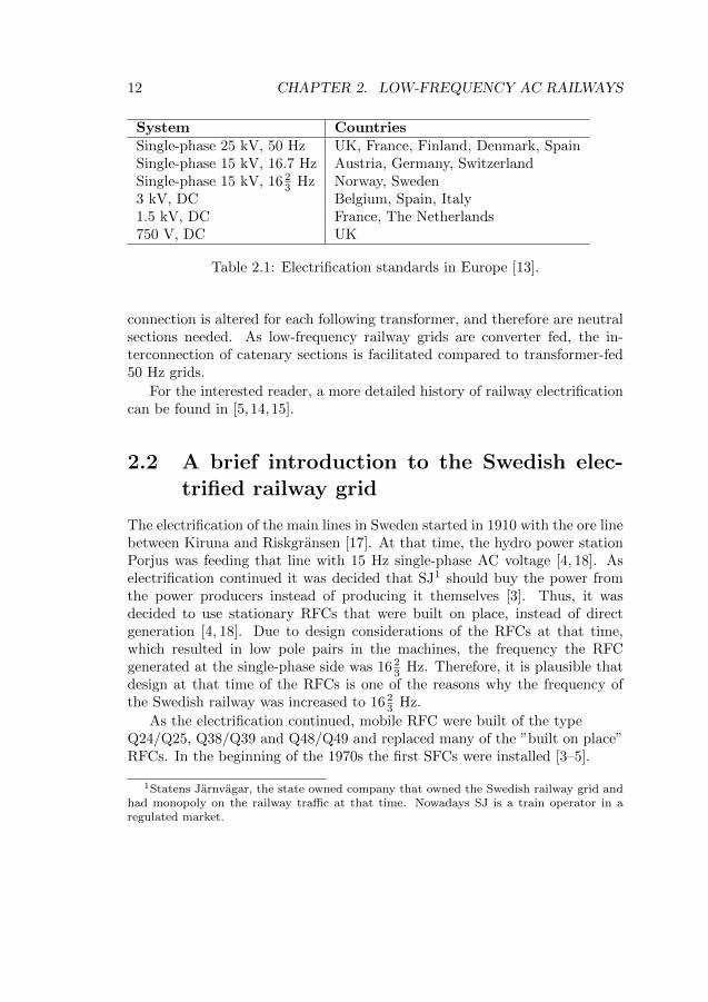
Austria, Germany, Norway, Sweden, Switzerland and the U.S. chose toelectrify their railway grids with single-phase low-frequency AC. Other coun-tries continued with DC or did not electrify until some decades later whenthe technology allowed 50 Hz single-phase electrification for their railway grid.The standards of electrical railways used in Europe are presented in Table 2.1.
Note the difference between the two single-phase 15 kV standards in Ta-ble 2.1, which is further explained in Sections 2.5 and 2.6.
One main advantage of low-frequency AC is that it allows power transferover longer distances as the reactance is lower compared to 50 Hz.
In transformer-fed 50 Hz railway grids, the transformers feeding the rail-way are connected to two phases of the three-phase grid, which causes anunbalance. To avoid excessive unbalance of the three-phase grid, the phase
11
12 CHAPTER 2. LOW-FREQUENCY AC RAILWAYS
System CountriesSingle-phase 25 kV, 50 Hz UK, France, Finland, Denmark, SpainSingle-phase 15 kV, 16.7 Hz Austria, Germany, SwitzerlandSingle-phase 15 kV, 16 2
3 Hz Norway, Sweden3 kV, DC Belgium, Spain, Italy1.5 kV, DC France, The Netherlands750 V, DC UK
Table 2.1: Electrification standards in Europe [13].
connection is altered for each following transformer, and therefore are neutralsections needed. As low-frequency railway grids are converter fed, the in-terconnection of catenary sections is facilitated compared to transformer-fed50 Hz grids.
For the interested reader, a more detailed history of railway electrificationcan be found in [5, 14,15].
2.2 A brief introduction to the Swedish elec-trified railway grid
The electrification of the main lines in Sweden started in 1910 with the ore linebetween Kiruna and Riskgransen [17]. At that time, the hydro power stationPorjus was feeding that line with 15 Hz single-phase AC voltage [4, 18]. Aselectrification continued it was decided that SJ1 should buy the power fromthe power producers instead of producing it themselves [3]. Thus, it wasdecided to use stationary RFCs that were built on place, instead of directgeneration [4, 18]. Due to design considerations of the RFCs at that time,which resulted in low pole pairs in the machines, the frequency the RFCgenerated at the single-phase side was 16 2
3 Hz. Therefore, it is plausible thatdesign at that time of the RFCs is one of the reasons why the frequency ofthe Swedish railway was increased to 16 2
3 Hz.
As the electrification continued, mobile RFC were built of the typeQ24/Q25, Q38/Q39 and Q48/Q49 and replaced many of the ”built on place”RFCs. In the beginning of the 1970s the first SFCs were installed [3–5].
1Statens Jarnvagar, the state owned company that owned the Swedish railway grid andhad monopoly on the railway traffic at that time. Nowadays SJ is a train operator in aregulated market.
2.3. CATENARY SYSTEMS 13
Sweden has about 11200 km of electrified railway [19], and the total in-stalled amount of power conversion capacity by 2013 was approximately 1300MVA, 60% of the installed power conversion capacity consisted of SFCs.
2.3 Catenary systems
The mechanical construction of the catenary system can be more complexcompared to ordinary power lines [4]. For example the mechanical tension ofthe catenary has to be constant independently of the ambient temperature [4].
One of the simplest catenary systems, in terms of the power supply, is tohave one conductor supplying the train, with the rail/earth as return conduc-tor. However, if the return current returns via the rail and ground, there is aconsiderable possibility for stray currents that may cause interference [20].
To avoid return currents through rail and earth, transformer solutions canbe used in combination with extra conductors. There are two main types oftransformer-based solutions for catenary systems, which are Booster Trans-former (BT) and Auto Transformer (AT), which are treated in the followingsubsections.
2.3.1 BT Systems
The utilization of BTs is desired in countries where the earth resistivity ishigh, like in Sweden. When BTs are used in the catenary, the return currenton the rail is drawn up by the BT to a return conductor [20,21]. The BT withreturn conductor system results in reduced rail currents and the therefore inreduced rail potential. Stray current are also reduced, resulting in reducedinterference with telecommunications circuits. [20, 21].
The BTs are connected in series, which results in the currents needingto flow through each BT in the catenary to the train locations and back tothe converter station. An equivalent impedance of a BT catenary system ishigh as the ground cannot be used as a return path [22]. Depending on sizeand the amount of return conductors, there are several BT caternay systemconfigurations, all of them with different equivalent impedances. Equivalentimpedances of BT catenary systems of the Swedish railway grid can be foundin [23].
14 CHAPTER 2. LOW-FREQUENCY AC RAILWAYS
2.3.2 AT Systems
Using ATs in the catenary system allows the effective transfer voltage to beraised, without affecting the voltage seen by the trains. The AT is a trans-former where the midpoint is connected to ground. The voltage between thecontact line and rail is the same, but the voltage between the contact line andan additional conductor2 is typically increased [22]. If the winding ratio ofthe AT is 1:1, the voltage in the additional conductor and contact line will beequal in magnitude, but with opposite signs and thus the feeding voltage isdoubled [20,21,24].
The main benefit of AT is the reduction of transmission losses and theincreased ability to keep voltages at nominal levels. The main disadvantage ofAT catenary systems is that they only make it preferable for the return currentto flow in the additional conductor, as opposed to the BT catenary systemwhere the return current is forced into the return conductor. Therefore, thereis a greater possibility of stray currents with an AT catenary system than witha BT catenary system.
More details about models and simulations with AT catenary systemscan be found in [24–27]. Depending, for instance on size of the additionalconductor, equivalent impedances for some AT systems for the Swedish railwaygrid can be found in [23].
2.4 High voltage transmission systems
In order to strengthen a low-frequency AC railway grid, a parallel High VoltageTransmission (HV-T) system can be installed. In Norway a 55 kV HV-Tsystem is used to strengthen the railway grid. In Sweden a 132 kV HV-Tsystem is installed [4]. The Swedish 132 HV-T system is described in PaperVIII and in [4, 20,28].
In Germany an HV-T of 110 kV is used to feed the catenary via transform-ers, and most of the 110 kV HV-T is fed via large-size converters or powerplants [22, 29]. More information about this type of HV-T system and otherHV-T systems used in Europe can be found in Paper VIII and in [13,29].
2The additional conductor is often called ”negative feeder”
2.5. FREQUENCY CONVERTERS 15
2.5 Frequency converters
As the frequency of low-frequency railway grids is different from the publicgrid frequency of 50 Hz or 60 Hz, conversion of frequency is needed. Thefrequency conversion can be done with Rotary Frequency Converters (RFCs)or Static Frequency Converters (SFCs). The following subsections describethese two types of converters.
2.5.1 Rotary Frequency Converters
An RFC is a three-phase motor and single-phase synchronous generator mountedon the same mechanical shaft [30]. The pole ratio between the motor and thegenerator is three for the RFC used in Europe and 2.4 in the U.S.
There are two types of RFCs used in low-frequency AC railways:
• Synchronous-Synchronous
• Asynchronous-Synchronous.
2.5.1.1 Synchronous-Synchronous RFC
When the motor of an RFC is a synchronous motor, the RFC is said to besynchronous-synchronous. This type of RFC is used in Norway, Sweden, NorthEastern U.S. and in some parts of Germany. The motor has 12 poles pm andthe generator has 4 poles pg in Norway and Sweden, resulting in the pole ratiobeing three [5]. As the rotors of both synchronous machines are mounted onthe same mechanical shaft and with the assumption that the mechanical shaftis stiff, conversion of frequency is
ωmech = ω50elec
2
pm(2.1a)
ω16 2
3
elec = ωmechpg
2, (2.1b)
where ωmech is the mechanical speed of the rotors, ω50elec is the electrical rotor
speed of the motor and ω16 2
3
elec is the electrical rotor speed of the generator.The frequency of an RFC-fed railway grid will follow the frequency of the
public grid, but with a scaling factor of one third as seen in Equation (2.1)under steady-state. Due to the use synchronous-synchronous machine solu-tion, active power flow through a synchronous-synchronous RFC is dependent
16 CHAPTER 2. LOW-FREQUENCY AC RAILWAYS
on the voltage angle difference between the three-phase grid and single-phaserailway grid at the point of connection of the RFC.
The inherent power pulsation of twice the line frequency that exist insingle-phase systems is reduced by the rotating masses and with large damperwindings on the generator [5, 30].
Each of the synchronous machines of the RFC are equipped with their ownexcitation system, and voltage or the reactive power can be controlled on eachside of the RFC.
The downside of RFCs compared to SFCs is that they have long-start uptimes according to [3, 5].
2.5.1.2 Asynchronous-Synchronous RFC
If the motor of the RFC is an induction motor, the RFC is said to be asyn-chronous-synchronous. This type of RFC is used in Austria, Germany andSwitzerland [14,15]. For steady state, a simplified expression of the conversionof frequency is
ωmech = (1− s) · ω50elec
2
pm(2.2a)
ω16 2
3
elec = ωmechpg
2, (2.2b)
where ωmech is the mechanical speed of the rotors, s is the slip, ω50elec is the
electrical rotor speed of the motor, and ω16 2
3
elec is the electrical rotor speed ofthe generator.
The induction motor used here is a controllable motor where the rotor isequipped with three-phase winding and slip-rings, which provide the connec-tion with a variable-frequency source [31]. Using a variable-frequency sourceallows the RFC to control the active power-input to the railway grid [14].
However, when the slip is zero the RFC is at synchronous operation.The variable-frequency source connected to the induction motor will supplyDC then, causing thermal losses and reducing the life-span of the variable-frequency source [13, 15]. Thus, the nominal railway frequency was increasedto 16.7 Hz in Austria, Germany and Switzerland. The active power throughsuch an RFC is dependent on the frequency at the point of connection at thesingle-phase side, which follows a power-frequency droop characteristic [29].
Like for a synchronous-synchronous RFC, the public grid will see a control-lable asynchronous-synchronous RFC as a balanced load [31]. Some disadvan-tages compared to synchronous-synchronous RFCs is the harmonic emission
2.5. FREQUENCY CONVERTERS 17
from the variable-frequency sources, given it is a cyclo-converter, which canlead to poor power factor and excessive heating.
2.5.2 Static Frequency Converters
Three kinds of SFCs based on power electronics are commonly used for alltypes of low-frequency AC railways. Common for all kinds of SFCs is thatthey are controlled in such way that they mimic the steady-state behaviourof an RFC on the single-phase side.
2.5.2.1 Direct converters (Cyclo-converters)
Direct converters were introduced in the Swedish railway grid in the beginningof the 1970s [4]. The direct converter uses either 6-pulse bridge or a 12-pulsebridge connection [5, 32].
By controlling the firing angle of the thyristors, the output voltage on thesingle-phase side is controlled with the desired frequency [5, 32].
As the direct converters are line commutated converters, the strength ofthe supplying three-phase grid is important as the cyclo-converter generatesboth voltage and current harmonics, and consumes reactive power. To copewith the inherent 33 1
3 Hz power pulsation, filters have to be installed on thesingle-phase side. Filters are also required to filter harmonics on both sidesand provide reactive power support at the three-phase side.
2.5.2.2 DC-link converters
The DC-link converter is an SFC that consist of two converters with a com-mon DC link. The three-phase side of the converter rectifies the three phaseAC voltage to DC, whereas the single-phase Voltage Source Converter (VSC)inverts the DC voltage to a sinusoidal voltage.
For cost reasons, the first type of DC-link converters for railways had a12-pulse thyristor bridge instead of Gate Turn-Off (GTO) thyristors on thethree-phase side converter [14]. Therefore, there are some DC-link convertersthat cannot cope with regenerative power [5, 14]. However, nowadays mostDC-link converter has a VSC on the three-phase side.
The three-phase side converters’ main objective is to keep the DC-linkvoltage constant. The single-phase power pulsation twice the single-phase linefrequency is absorbed by a 33 1
3 Hz filter installed in the DC-link. Additionalfilters are also installed in the DC-link and on each side of the SFC to absorbhigher order harmonics that are generated by the converters.
18 CHAPTER 2. LOW-FREQUENCY AC RAILWAYS
The main advantage of VSC based DC-link converters is that they cancontrol the reactive power or control the voltage at the point of connection atthe three-phase side as well as at the single-phase side. The DC-link converterhas almost no requirement on the three-phase grid as they operate in all ofthe four quadrants of the PQ-plane.
On the single-phase side, several inverters are connected in parallel as eachinverter can only handle a restricted amount of power [5, 13]. The benefitswith many inverters is that the output voltage have less harmonics, as theoutput voltage from each individual inverter is displaced in a such way thatharmonics are reduced according to [5].
The downside of the DC-link converter based on VSC technology is thatthey are sensitive to over-currents, and can be difficult to protect [5]. Moredetails about DC-link converters for railways can be found in [5, 13,33,34].
2.5.2.3 MMC converters
Modular Multilevel Converts (MMC) of matrix type, form a new generationof multilevel VSCs. The main idea is to have several sub-modules in series,in which each sub-module has it owns storage capacitor [13, 35]. The MMCconfiguration used for low-frequency railways is the direct AC/AC config-uration [34]. The input voltage is three-phase AC and the output voltageis single-phase AC. Choosing a high number of sub-modules for the neededpower level results in line filters not being a must, and the risk of resonanceis reduced according to [13].
2.6 Synchronous and Asynchronous railway grids
There are two types of low-frequency railway grids in Europe, a synchronous3
and an asynchronous 4.
Austria, Germany and Switzerland decided in the beginning of the 20:thcentury to build up their own railway grid, with hydro-power plants, ther-mal plants and with asynchronous-synchronous RFC. The generators are con-nected to a high voltage transmission system via step-up transformers, and thecatenary is fed via step-down transformers from the high voltage transmissionsystem. This kind of low-frequency railway grid is operated in a similar wayas a three-phase public grid, in the sense that the railway grid power operator
3Also called frequency-stiff or decentralized railway grid4Also called frequency-elastic or centralized railway grid
2.6. SYNCHRONOUS AND ASYNCHRONOUS RAILWAY GRIDS 19
is also responsible for maintaining the frequency. The frequencies of asyn-chronous railway grids are allowed to vary between −3%/+ 2% [36]. Detailsof asynchronous railway grids can be found in Paper VIII and in [13,14].
The railway grids of Norway, Sweden and North Eastern U.S. are of syn-chronous type. The frequency of the railway grid is in Scandinavia exactlyone third of the frequency in the public three-phase grid, in steady-state.
High voltage transmission is used to reduce the impedance and increasethe possible physical distance between converter stations. However, due to thevoltage phase differences in the three-phase grid, active power will also flowat no-load situations into the railway grid. This used to be especially true forthe northern part of the Swedish railway grid, but the unwanted power flowsare reduced by the use of SFCs. Details can be found in Paper VIII andin [4, 13,14,20].
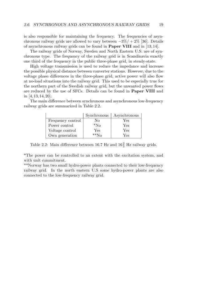
The main difference between synchronous and asynchronous low-frequencyrailway grids are summarized in Table 2.2.
Synchronous AsynchronousFrequency control No YesPower control *No YesVoltage control Yes YesOwn generation **No Yes
Table 2.2: Main difference between 16.7 Hz and 16 23 Hz railway grids.
*The power can be controlled to an extent with the excitation system, andwith unit commitment.**Norway has two small hydro-power plants connected to their low-frequencyrailway grid. In the north eastern U.S some hydro-power plants are alsoconnected to the low-frequency railway grid.

20 CHAPTER 2. LOW-FREQUENCY AC RAILWAYS
Chapter 3
Power System StabilityDefinitions andClassifications
This chapter describes the power system’s stability definitions and the classi-fications commonly used for stability studies.
3.1 Definitions
A power system is defined by [37] as:
A network of one or more electrical generating units, loadsand/or power transmissions lines, including the associated equip-ment electrically or mechanically connected to the network.
With the above definition given of a power system, the proposed stabilitydefinition by [38] is:
Power system stability is the ability of an electric power system,for a given initial operating condition, to regain a state of operatingequilibrium after being subjected to a physical disturbance, withmost system variables bounded so that practically the entire systemremains intact.
21
22 CHAPTER 3. POWER SYSTEM STABILITY
3.2 Classifications
A power systems is always in motion, as load fluctuates and generation isconnected and disconnected. From an engineering point of view, a powersystem will be considered stable for a certain time period for a given initialoperating condition [39]. Thus, if a measured or calculated physical quantitysuch as for example voltage magnitude and phase angle are constant in time,the system is in steady state [40].
If a change occurs in the power system that results in the system operatingquantities to change, the power system undergoes a disturbance [40–42]. Itexists two types of disturbances in a power systems [40,42]
• small disturbances and
• large disturbances.
If the power system is subjected to a small disturbance, the equations describ-ing the power system can be linearised for the purpose of the analysis [42].Small disturbances are for example small changes in load or generation [40,41].
A large disturbance is a disturbance for which the power system equationscannot be linearised [42]. Examples of large disturbances are short-circuits,loss of generation and connection or disconnection of large loads [40,41].
If a power system is subjected to a small disturbance and is able to returnto the same steady-state condition as before the disturbance, the power systemis said to be steady-state stable [40, 42]. However, if the disturbance is largea power system may reach a new stable operating state that is different fromthe initial operating state. The power system is said to be transiently stable[40, 42].
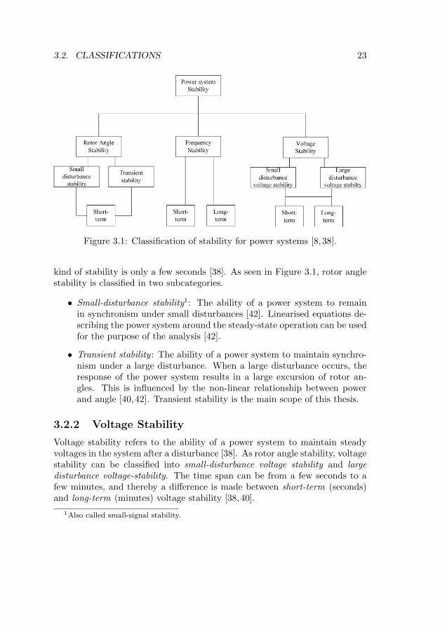
Power systems are complex and simplifications need to be made such thatthe operational modes that results in instability can be observed [38,39]. De-pending on which parameters are most affected after a disturbance, three typesof stabilities are distinguished: Rotor Angle, Voltage and Frequency [38]. Thementioned stability can be classified as short-term stabilities or long-term,depending of the time span for actions [10,40]. Figure 3.1 presents a diagramof the different power system classifications.
3.2.1 Rotor Angle Stability
Rotor angle stability refers to the ability of synchronous machines in an inter-connected power system to remain in synchronism with each other after thepower system is being subjected to a disturbance [39]. The time span of this
3.2. CLASSIFICATIONS 23
Figure 3.1: Classification of stability for power systems [8, 38].
kind of stability is only a few seconds [38]. As seen in Figure 3.1, rotor anglestability is classified in two subcategories.
• Small-disturbance stability1: The ability of a power system to remainin synchronism under small disturbances [42]. Linearised equations de-scribing the power system around the steady-state operation can be usedfor the purpose of the analysis [42].
• Transient stability : The ability of a power system to maintain synchro-nism under a large disturbance. When a large disturbance occurs, theresponse of the power system results in a large excursion of rotor an-gles. This is influenced by the non-linear relationship between powerand angle [40,42]. Transient stability is the main scope of this thesis.
3.2.2 Voltage Stability
Voltage stability refers to the ability of a power system to maintain steadyvoltages in the system after a disturbance [38]. As rotor angle stability, voltagestability can be classified into small-disturbance voltage stability and largedisturbance voltage-stability. The time span can be from a few seconds to afew minutes, and thereby a difference is made between short-term (seconds)and long-term (minutes) voltage stability [38,40].
1Also called small-signal stability.
24 CHAPTER 3. POWER SYSTEM STABILITY
For example HVDC and inductions motors impact the voltage stabilityon the short-time scale [38], whereas tap-changing transformers impact thevoltage stability on the long-term scale [38].
3.2.3 Frequency Stability
Frequency stability is the ability of a power system to keep the frequency closeto nominal after a significant imbalance between power generation and powerconsumption [38]. Any disturbance, small or large, could concern frequencystability [40]. The main difference between rotor angle stability and frequencystability is that the latter one concerns the overall response of the powersystem(s) [40].
Chapter 4
Stability in Railway PowerSystems
This chapter provides an overview of the literature on stability in AC railways.
4.1 Rotor Angle Stability
4.1.1 Transient Stability
Besides the research and work done in this thesis on transient stability of low-frequency AC railways, the reported work on this area is small to its number.
According to [16], concerns about synchronous-synchronous RFCs losingsynchronism has been a stability question of major concern. Danielssen [16]refers to the study in [43] done in 1972. The study done in [43] concludes thatan RFC would not lose synchronism after a short-circuit on the single-phaseside according to [16].
In [44], the transient stability of the northern part of the Swedish railwaygrid was investigated, when the Swedish Transport Administration built alow-frequency high voltage transmission line, in parallel with the catenarysystem. It was concluded that the possibility of an RFC losing synchronismis low. However due to the simple models used, the conclusion is only validfor ”first-swing”. In addition, the study does not address the question of howthe transient stability is affected by SFCs being introduced.
A study [45] investigates the transient stability of the 25 Hz AMTRAKrailway grid in the U.S. The study contains models of RFCs, SFCs and dy-
25
26 CHAPTER 4. STABILITY IN RAILWAY POWER SYSTEMS
namical models of a train. The study showed that the faults applied did notlead to instability. However, parameter data about the models are not known.Furthermore, the SFC model didn’t have any current limitation implemented.
4.1.2 Small-signal Stability
4.1.2.1 Low-frequency oscillations in 16 23 Hz railways
Low-frequency oscillations between railway vehicle and synchronous-synchro-nous RFCs were observed in Norway 1996 [16]. Investigations and modellingwere done internally at Jernbaneverket1 [46]. The modelling and observationsare summarized in [47], where one of the main conclusions was that an RFCof a certain type has a poor damped electromechanical eigenfrequency atapproximately 1.6 Hz, due to the lack of explicit damper windings on theRFCs motor [16].
The interactions between the RFC’s poorly damped eigenfrequency and arailway vehicle are studied in detail in [16]. The work done in [16] presentsmethods for studying the interactions, and proposes different approaches onhow the controls of the railway vehicle can be used to counteract the poorlydamped eigenfrequency of the RFC.
4.1.2.2 Low-frequency oscillations in 50 Hz railways
Low-frequency power oscillations are also of concerns in 50 Hz railway sys-tems, especially when several trains are in a depot (also known as the ”depotproblem”2) where auxiliary power of the train is the only power consumed.However, this type of instability has little to do with rotor angle instabilityas 50 Hz railway systems is mainly transformer fed.
A lot of effort is put into the modelling to capture the mechanism of low-frequency oscillations in 50 Hz railway systems. Papers like [48–55] use someof the methodologies proposed by [16], where the interaction between one orseveral Electric Multiple Units (EMUs) with they supply system and with eachother is investigated. Most of the mentioned papers use impedance methodsin dq-frame for small-signal modelling of the EMU’s line-side converter andthe supply system to investigate the low-frequency oscillations.
1The Norwegian railway administration2The depot problem is also of concern for low-frequency railway grids.
4.2. VOLTAGE STABILITY 27
4.2 Voltage Stability
According to [16], which refers to [56], when doing railway power system stud-ies voltage drops are commonly treated as part of voltage quality and voltagelevel variations, instead of voltage stability and collapse. Before voltage col-lapse can occur, the protection system of the train will often have alreadytriggered on under-voltage and the circuit breakers of the train are opened.The voltage level at which the circuit breakers of the train should open areset by the European Standard EN50388 [16,57].
The requirement of maximum and minimum voltage levels at the train andpower supply are set by the standards EN50388 [57] and EN50163 [36]. Theimpact of voltage levels at train locations is investigated in [58]. Low voltagesat train locations can result in train delays as the train(s) have to reduce theirpower consumption.
A case of voltage collapse in 50 Hz railway is studied in [59], where the trainheadway between two train is reduced until voltage collapse occurs. However,the the study uses constant power loads, and does not consider the voltagedependency that trains have.
Simulations and studies of train traffic and its impact on voltage levelsis studied by the infrastructure manager/owner [16]. Such studies are oftentime consuming, but required to investigate the need of investment in newconverter stations to keep acceptable voltage levels. Reducing the simulationtime is of interest and [20] proposes methods based on neural networks.
4.3 Frequency Stability
4.3.1 Low-frequency AC railways
Due to the use of synchronous-synchronous RFCs in the Norwegian, Swedishand North Eastern U.S. railway grids, frequency stability is not an issue. Evenwith SFCs, at least for normal steady state operation, the frequency of therailway grid is linked to the public grid frequency [39].
In the asynchronous low-frequency AC railway grids in Central Europe,studies regarding frequency stability have been performed.
In [29] the frequency stability of the German single-phase 110 kV networkis investigated, with increasing use of SFCs. The study focuses on the worstcase scenario, which is the loss of a 150 MW generation unit. It is concludedthat frequency will fall, but stabilize within the acceptable range, and thatreplacing RFCs with SFCs the frequency stability will not be endangered.
28 CHAPTER 4. STABILITY IN RAILWAY POWER SYSTEMS
The frequency stability of a major part of the Swiss and German electricalrailway grid network is investigated in [60]. The concern is how the variation ofthe fundamental frequency will affect higher order harmonics, as the frequencyis allowed to vary between 16.19 Hz and 17.03 Hz. The conclusion was that thetime-varying fundamental frequency produced time-varying harmonics thatimpacts the evaluation of interference with the signalling system.
4.3.2 Frequency stability in transformer fed 50 Hz rail-ways
Using the same approach as in [60], the impact of frequency deviation inthe French 50 Hz grid is studied in [61]. Similar conclusions as in [60] aremade, that any drift of the fundamental frequency may result in amplificationof hight order harmonic frequencies. Which may impact the evaluation ofinterference of high-order harmonics with the signalling circuits [61].
Chapter 5
Mathematical model of apower system
This chapter provides a mathematical description of a power system, and themathematical foundation that this work is based on.
5.1 Mathematical model
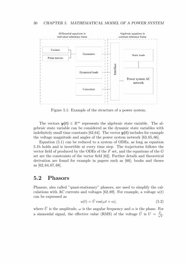
A power system, as shown in Figure 5.1, can be described by a set of differen-tial and algebraic equations. The algebraic equations (5.1b) are for examplethe generator stator equations, the grid equations and the static load modelsin a common reference frame [8, 10, 62].The differential equations (5.1a), de-scribe for example the rotor circuit equations and converter equations in anindividual reference frame [8, 10, 62]. Note that dynamic loads and convert-ers can be also be described as differential equations in a common referenceframe, without the need for an interface. The mathematical model of a powersystem for electromechanical dynamical studies can be described accordingto [42,62–66] as
F set: x(t) = f(x(t), y(t)) (5.1a)
G set: 0 = g(x(t), y(t)). (5.1b)
The vectors x(t) ∈ Rn represents the dynamic state variables of power systemequipments which time constants cannot be neglected [64]. It includes forexample the synchronous machine speed and field voltage.
29
30 CHAPTER 5. MATHEMATICAL MODEL OF A POWER SYSTEM
Figure 5.1: Example of the structure of a power system.
The vectors y(t) ∈ Rm represents the algebraic state variable. The al-gebraic state variable can be considered as the dynamic state variables withindefinitely small time constants [62,64]. The vector y(t) includes for examplethe voltage magnitude and angles of the power system network [63,65,66].
Equation (5.1) can be reduced to a system of ODEs, as long as equation5.1b holds and is invertible at every time step. The trajectories follows thevector field of produced by the ODEs of the F set, and the equations of the Gset are the constraints of the vector field [62]. Further details and theoreticalderivation are found for example in papers such as [66]; books and thesesas [62,64,67,68].
5.2 Phasors
Phasors, also called ”quasi-stationary” phasors, are used to simplify the cal-culations with AC currents and voltages [62, 69]. For example, a voltage u(t)can be expressed as
u(t) = U cos(ωt+ α), (5.2)
where U is the amplitude, ω is the angular frequency and α is the phase. For
a sinusoidal signal, the effective value (RMS) of the voltage U is U = U√2.
5.2. PHASORS 31
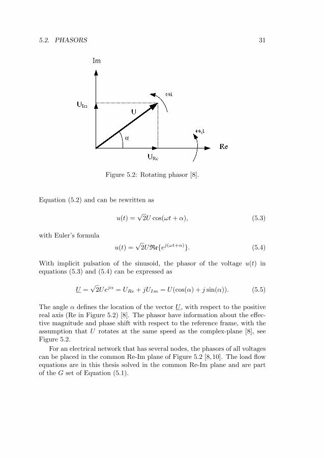
Figure 5.2: Rotating phasor [8].
Equation (5.2) and can be rewritten as
u(t) =√
2U cos(ωt+ α), (5.3)
with Euler’s formula
u(t) =√
2UReej(ωt+α). (5.4)
With implicit pulsation of the sinusoid, the phasor of the voltage u(t) inequations (5.3) and (5.4) can be expressed as
U =√
2Uejα = URe + jUIm = U(cos(α) + j sin(α)). (5.5)
The angle α defines the location of the vector U , with respect to the positivereal axis (Re in Figure 5.2) [8]. The phasor have information about the effec-tive magnitude and phase shift with respect to the reference frame, with theassumption that U rotates at the same speed as the complex-plane [8], seeFigure 5.2.
For an electrical network that has several nodes, the phasors of all voltagescan be placed in the common Re-Im plane of Figure 5.2 [8,10]. The load flowequations are in this thesis solved in the common Re-Im plane and are partof the G set of Equation (5.1).
32 CHAPTER 5. MATHEMATICAL MODEL OF A POWER SYSTEM
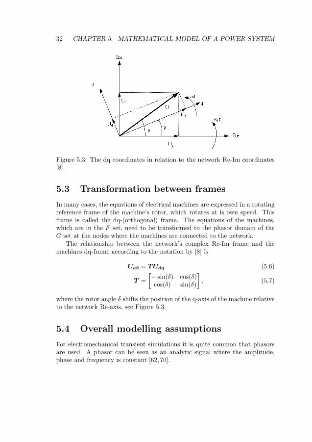
Figure 5.3: The dq coordinates in relation to the network Re-Im coordinates[8].
5.3 Transformation between frames
In many cases, the equations of electrical machines are expressed in a rotatingreference frame of the machine’s rotor, which rotates at is own speed. Thisframe is called the dq-(orthogonal) frame. The equations of the machines,which are in the F set, need to be transformed to the phasor domain of theG set at the nodes where the machines are connected to the network.
The relationship between the network’s complex Re-Im frame and themachines dq-frame according to the notation by [8] is
Uab = TUdq (5.6)
T =
[− sin(δ) cos(δ)cos(δ) sin(δ)
], (5.7)
where the rotor angle δ shifts the position of the q-axis of the machine relativeto the network Re-axis, see Figure 5.3.
5.4 Overall modelling assumptions
For electromechanical transient simulations it is quite common that phasorsare used. A phasor can be seen as an analytic signal where the amplitude,phase and frequency is constant [62,70].
5.4. OVERALL MODELLING ASSUMPTIONS 33
As stated by [62], the assumptions for using the phasor approach is thatthe system is in steady-state and all harmonics are neglected (i.e a perfectsinusoidal signal). Thus, the phasor approach is inconsistent with transientanalysis of power systems, as the frequency changes during a transient [62].However, under quasi-stationary assumption, phasor can be used. Quasi-stationary assumption is when the transients are slow enough that they canbe approximated to be stationary [62, 70]. In other words, the dynamic phe-nomena is considerable slower than system frequency, and electromechanicaltransients satisfy the quasi-stationary assumption [62,66,69,70].
All models used in this work are designed to comply with the phasorparadigm, and are valid under the quasi-stationary assumptions.

34 CHAPTER 5. MATHEMATICAL MODEL OF A POWER SYSTEM
Part II
Results of the Thesis
35

Chapter 6
Models developed
This chapter treats the models proposed of an RFC and an SFC developed inthis thesis, which originates from Paper I and Paper II.
6.1 Proposed RFC model, Paper I
6.1.1 Summary
The main motivation and purpose of Paper I is to propose and describea synchronous-synchronous RFC model for electromechanical studies in thephasor domain. Paper I presents a detailed description of a synchronous-synchronous RFC, and the model is based on the Anderson-Fouad synchronousmachine model [9, 71].
The behaviour of the RFC model is illustrated for single-feeding anddouble-feeding configurations, where the RFC type Q48/Q49 is used. Oneof the main findings is that the rotor speed deviation oscillations after a largedisturbance is around 1.96 Hz for RFC type Q48/Q49.
Paper I illustrates also a concept for RFC model to be implemented forsystem stability studies, and provides a starting platform for future studiesand possible model adjustments.
37
38 CHAPTER 6. MODELS DEVELOPED
6.1.2 Modelling discussion
6.1.2.1 Single-phase machine as a three-phase machine
The single-phase generators of the RFCs (as all large single-phase machines)are designed with more effectively damping damper windings, compared toa typical three-phase machine, to counteract the second harmonic inducedin the stator [31]. The single-phase generator model in this thesis has beendescribed with a three-phase synchronous machine model, likewise in [7,16,44].The RFC model proposed in Paper I has been derived from standard (three-phase) synchronous machine models. The efficient damping of the single-phase machine’s rotor, results in the rotor to experience a reduced share ofthe second order harmonics from the grid/stator. The lesser the impact of thesecond order harmonics on the rotor, the more valid, the three-phase machinemodel of the single-phase machine becomes.
6.1.2.2 Stator transients
In the overall modelling, transients associated with power/current flows inthe railway grid and the public grid are assumed to have a fast decay time, sothat a QSS (Quasi Steady-State)1 [64,67] approach is used. As grid transientsare neglected, the stator transients of the RFC machines have to be neglected[8, 10].
The difference between including and neglecting stator transients is il-lustrated in [10, Section 5.1.1]. In that example, it is shown that the negli-gence of stator transients makes the transients of Id, Iq, and T non-oscillatory,whereas they oscillate after a cleared fault without this negligence. Moreover,in that example, the rotor angle oscillations are shown to be exaggeratedand slightly slower making this negligence. Also, the rotor speed deviationbecomes greater using this negligence than not doing so; and the oscillatorybehaviour of the rotor speed deviation before fault clearing vanishes using thisnegligence, according to the example in [10, Section 5.1.1]. Krause et. al [72]discusses further the effects of neglecting the stator transients. Results pre-sented in [72, Figure 1, Figure 2] verifies the examples made by [10, Section5.1.1].
For public power systems, the increased rotor speed deviation of thisnegligence introduces a conservatism to the model. However, RFC-fed syn-chronously operated (single-phase) low-frequency railway grids have many op-erating conditions differing from public transmission grids fed by thermal or
1See Chapter 5
6.2. PROPOSED SFC MODEL, PAPER II 39
hydro-power generators. One important reason for this is that the mechanicpower of the generator shaft is provided by another synchronous machine forsynchronous railway grids. How the negligence of stator transients impacts theRFC has not been investigated. However, for the modelling purposes and asthe single-phase generator is modelled as a three-phase synchronous machine,the stator transients are neglected.
6.1.2.3 Sub-transient saliency
It is written in Paper I that sub-transient reactance are set equal, and thussub-transient saliency is neglected on both motor and generator. However, thesub-transient saliency does not have to be neglected on the motor side of theRFC model proposed. The RFC model is capable of handling sub-transientsaliency, with the model for connecting the three-phase grid to the RFC motorused. Therefore, the assumption made in the paper regarding saliency on theRFC motor can be neglected, as long as the model of connection betweenthree-phase grid and RFC motor is used.
6.2 Proposed SFC model, Paper II
6.2.1 Summary
The main aim of Paper II is to provide a simple and open model of an SFC in-tended for performing electromechanical stability studies. Current limitationis included in the proposed SFC model. The SFC is modelled as a controllablevoltage source, connected to the busbar via a transformer and an additionalinductance in series to the railway grid.
Measured data of RMS voltage and current was obtained from an SFCoperating in the Swedish railway grid. However, the measured data availablewas only from the inverter side of the SFC and no data was available fromthe rectifier side. Therefore, it was decided for simplicity of the modelling toassume that the DC capacitance of the SFC is large enough to always keepconstant DC voltage. Thus, the rectifier of the SFC can be neglected.
For reproducing the measured data, the model was validated against fourmeasured events. Two events when current limitation never was activated andtwo events when current limitation was activated.
One of the events where current limitation was never activated, was used toadjust and validate the SFC model’s phase and voltage controller parameters.
40 CHAPTER 6. MODELS DEVELOPED
The second event was used to validate the parameters of the phase and voltagecontroller of the SFC model.
In the similar way, one of the events where current limitation was acti-vated, was used to adjust and the validate the current limitation controller’sparameters of the SFC model. Whereas, the second event was used to validatethe SFC model’s current limitation controller.
As shown in Section 4 in Paper II, the model is able to follow the measuredRMS data with an acceptable accuracy. Wind-up in voltages are properly de-scribed by the SFC model, and currents produced by the model follows themeasured current. The main conclusion that can be drawn is that the pro-posed SFC model provides an adequate description of the main characteristicsof an SFC inverter during normal operation and current limit operation.
Chapter 7
Transient stability studies
This chapter summarizes the transient stability studies done in Papers III-VII. The results are based on the models developed in this work and presentedin Chapter 6 and in Papers I-II.
7.1 RFC-fed railway grids
Paper III and Paper IV explores the transient stability with RFC-fed rail-ways trough numerical simulations using the model of the RFC developed inPaper I.
In Paper III, the transient stability of a simple synchronous low-frequencyrailway grid is investigated, regarding the type of catenary system used andthe impact of different distributions of RFC types (Q38/Q39 and Q48/Q49)between converter stations, as well within a converter station.
The trains are modelled as PQ nodes for the steady-state simulations,whereas for the dynamical simulation the trains are modelled as constant shuntadmittances. The value of the shunt admittances is based on the pre-faultvalue of the voltage at the train locations. Furthermore, the train positionsare fixed.
Some of the findings from Paper III are that active power oscillationsincreases with an AT system compared to a BT system, as converter stationsare electrically closer to each other with an AT system compared to a BTsystem. Voltage drops during faults are deeper with AT than with BT. An-other finding was that different distribution of RFCs led to more active poweroscillations.
41
42 CHAPTER 7. TRANSIENT STABILITY STUDIES
Paper IV continues the exploration of the transient stability when havingan HV-T1. system in parallel with a BT catenary system. The system has twoconverter stations, and is investigated for different distribution of RFC types.
The system is investigated at no-load situation, in order to avoid the influ-ence from the load on the power oscillations. Some of the finding is that whenthe system is only fed with the RFC type Q38/Q39 the rotor oscillations areabout 1.68 Hz, which is in line with [16]. For the RFC type Q48/Q49 the rotoroscillations are about 1.96 Hz. Having a mix of these two types of RFC, one ofthe finding is rotor oscillations at a frequency about 1.84-1.87 Hz. The rotoroscillations was the machine-rated-weighted average of the rotor oscillationsof the RFC type Q38/Q39 and RFC type Q48/Q49.
Having a mix of RFC types in a converter station resulted in the activepower of each RFC to be phase and amplitude modulated, see Figure 5bin Paper IV. Thus, the total active power output is approximately zero atcertain time periods of time.
7.2 Replacing RFCs with SFCs
The effects on transient stability by replacing RFCs with SFCs, is studied inPaper V. The system is studied in a no-load situation with a BT caternarysystem, with four converter stations with only one RFC/SFC activated ineach station for simplicity. Five cases are investigated, and in each case oneQ48/Q49 RFC type is replaced with a 15 MVA SFC.
The numerical simulations show that replacing RFCs with SFCs resultsin magnitudes of the active- and reactive power oscillations to increase. Thesimulations shows also that rotor oscillations of an RFC increases in magnitudeand in frequency for each replacement.
7.3 Impact of load models in a RFC-fed railway
To provide alternative, but not too detailed load models, two types of loadsare studied and compared in Paper VI and Paper VII.
In paper Paper VI, the active power consumption of the train is voltage-regulated. The train model is intended to describe the behaviour of a trainduring a transient, which is described in [44].
One of the findings is that the BT system causes the voltage-regulatedtrain to more often enter abnormal operation than the AT system, in the
1See Section 2.4
7.4. BRIEF SUMMARY OF PAPER VIII 43
sense that there is no clear steady-state voltage at the train and thereforeno stable power consumption of the train. The reason is that after the faultbeing cleared, the system undergoes a change from a low impedance systemto a high impedance system. The result is that the transferability is limitedas the voltage level drop is to deep, why the pre-fault active power consumedcannot be delivered. See for example Figure 9 in Paper VI.
A constant current train model is used in Paper VII to investigate theimpact of such a load model on the stability. One of the findings is thatthe system clearly becomes more oscillative with an AT-system than with aBT system. The influence of the RFC type feeding the system affects theoscillations occurred, especially in the voltage magnitude at the train locationdepending on which RFC type is used.
Comparing the two load models with each other, the voltage-regulatedtrain model provides a more realistic view as the vast majority of trains havea power consumption that is voltage dependent. As mentioned earlier, thevoltage-regulated train may enter in abnormal operation. However, with thevoltage-regulated train only minor power or voltage magnitude oscillationsare observed in the system. The constant current train model results in morevoltage magnitude oscillations at the train locations and in the system, andmore active power oscillations are observed. Thus, the constant current trainmodel leads to a more oscillative system compared with voltage-regulatedtrain model.
7.4 Brief summary of Paper VIII
Paper VIII aims to presents the challenges with increased share of powerelectronic generation in railways, with focus on the Swedish one.
The paper describes actual phenomena’s measured in Sweden when havingRFCs and SFCs operating in parallel, or having SFCs of different manufac-tures operating in parallel.
The paper provides also technical background of low-frequency grids, anda comprehensive description and comparison between the two types of low-frequency AC railways grids used.

44 CHAPTER 7. TRANSIENT STABILITY STUDIES
Part III
Conclusions of the Thesis
45

Chapter 8
Conclusions
This chapter presents the overall conclusions of this thesis.
8.1 Models developed were needed
The number of publications of, and related to, transient stability of low-frequency AC railway grids is extremely small. The lack of published studiesand models is even more severe regarding SFCs for synchronous low-frequencyrailway grids. Considering the expected continued increase in use of SFCs inthe future, stability studies are likely to become more necessary.
Therefore, this thesis addresses an important need by proposing both anRFC and an SFC model. These models can be used as a foundation to startfrom for future and continued electromechanical analyses, as well as continuedmodel developments, of synchronous low-frequency AC railway grids.
8.2 The RFC model
The RFC model developed showed that, for studies of only one type of RFCsin the system, the electromechanical oscillations of the rotor where approx-imately 1.96 Hz for an RFC of type Q48/Q49 and approximately 1.67 Hzfor an RFC of type Q38/Q39. These results are validated for grids with oneor two converter stations. The oscillation frequency of the rotor of an RFCof type Q38/Q39 is in line with the results presented in [16] giving valid-ity to the model developed. The results in [16] comes from measurements,
47
48 CHAPTER 8. CONCLUSIONS
Simpow simulations, and from calculations based upon a second order ma-chine model. Besides the differences in rotor oscillation frequencies, the RFCtypes Q48/Q49 and Q38/Q39, seems to differ in behaviour in the sense thatQ38/Q39s give rise to higher amplitudes in the rotor speed deviations and inthe active power output oscillations.
8.3 The SFC model
An SFC is governed by its power electronics with corresponding fast controlsystems. The aim of the SFC model developed in Paper II was to reproducemeasured behaviour of an existing SFC in operation in the Swedish railway.In those measurements however, interactions with other converters were notobvious enough to be confirmed. One side of the SFC in question was single-side-feeding a section.
The validity of the SFC model is confirmed by comparing simulations re-sults using it with measurements. It can be concluded that the SFC modelcaptures the main characteristics of the measurements of a specific SFC ex-periencing transient disturbances.
8.4 Conclusions from numerical simulations
The transient stability of synchronous low-frequency AC railway grids hasin this thesis been studied through numerical simulations using the proposedmodels of an RFC and an SFC. The transient stability simulations done in thisthesis shows how a synchronous low-frequency railway grid may behave aftera large disturbance. It can be concluded that the synchronous low-frequencyrailway grids investigated are transiently stable.
The conclusion from the numerical simulations performed is that whenreplacing RFCs with SFCs, the system becomes less damped for each re-placement. The magnitudes and the frequencies of the rotor oscillations areincreased. Also active and reactive power oscillations increase in magnitude.
Having a purely SFC-fed railway grid, the system was stable and no ap-parent oscillations occurred in the simulations after fault clearance with theproposed SFC model. Given the models used, and the results of the simula-tions done, it may seem like that it is rather an increased mix of RFCs andSFCs that increases oscillations, rather than the SFCs themselves.
Chapter 9
Discussions
This chapter discusses the results and models in this thesis.
9.1 Three-phase grid impact
This thesis has neglected the impact on stability of three-phase grid weaknessby assuming that the RFC motors and SFC rectifiers are all connected toan infinite bus. The assumption was made to simplify the modelling andcalculations. In reality, interactions on the three-phase will occur, and theymight affect the stability.
9.2 Different converter types
9.2.1 Different RFC types behaviour
It still needs to be studied what causes the differences in oscillatory be-haviour after a transient disturbance. For example, the higher amplitudeof the Q38/Q39 oscillations could be explained by their lower apparent powerrating, but possibly also by other inherent differences in machine behaviour.It is noteworthy that the machine-rating-p.u. inertia H of the Q38/Q39 ishigher than that of the Q48/Q49 which could explain the lower frequency inthe rotor oscillations.
49
50 CHAPTER 9. DISCUSSIONS
9.2.2 Different RFC types as well as RFCs and SFCsoperating together
9.2.2.1 Different RFC types
Having a grid purely fed by RFCs of the Q38/Q39 type, the rotor oscillationswhere approximately 1.67 Hz, whereas they were 1.96 Hz for a grid purely fedby Q48/Q49s. However, when mixing the two types of RFCs the rotor oscil-lations of the Q38/Q39s increased as the rotor oscillations of the Q48/Q49sdecreased. The average rotor oscillations, of each of the RFCs in a system fedby one RFC of each type in two stations (four RFC units in total) coincidedwith the machine-rating-weighted average of the rotor oscillation frequencies,of the Q38/Q39 and the Q48/Q49, which is
4 MVA · 1.67 Hz + 10 MVA · 1.96 Hz
14 MVA.
9.2.2.2 RFCs and SFCs operating together
When, in Paper V, replacing Q48/Q49s with SFCs, the rotor oscillationfrequency increased for each replacement. This can probably be explained bythe fact that the response time for an SFC is much faster than it is to anRFC.
9.2.3 Larger and meshed test systems
This far, small, and mainly radial low frequency AC railway grids have beenstudied. However, converter (and vehicle) interactions might be different inmeshed grids.
9.3 RFC modelling
9.3.1 Sub-transient saliency
The model of the RFC presented in this paper neglects sub-transient saliency,assuming for simplicity that X ′′
d = X ′′q to avoid complicated calculations for
interlinking each machine’s rotor dq-frame to the network frame. The con-sideration of sub-transient saliency would improve the accuracy of the RFCmodel, especially on the motor-side.
For the two most common RFC types in Sweden, the fractionX′′
d
X′′q
ranges
from 0.91 to 1.20 on the generator sides, and between 0.69 to 0.70 on the
9.4. SFC MODELLING 51
motor sides. The importance and the impact of such a consideration is notclear since it has not yet been considered in any studies of synchronous low-frequency railway grids.
One possible approach to consider sub-transient saliency could be to intro-duce a dummy coil in the rotor [11]. That approach still allows non-iterativeload flows in the simulation. However, it is important to investigate howsuch an approach will impact the accuracy of the solution compared to othermore exact approaches. Moreover, if the accuracy is good-enough with thisapproach, compared to more exact approaches, it is important to determineif the improvement in accuracy is large enough to motivate the additionalcomputational complexity by adding one extra pair (one for the motor andone for the generator) of differential equations for each RFC in the system.
9.3.2 Validity of model parameters
Presented in [16], the sub-transient reactance in the q-axis had to be increasedto obtain simulation results reflecting the in-reality experienced instability.Therefore, it might be a general need for the parameters of the RFCs (c.f.Appendix A) to be thoroughly reviewed and validated. It is not well docu-mented how the RFC parameters were obtained (and to which extent theyever were verified against reality/measurements).
9.3.3 Excitation systems
In this thesis, the same excitation system model is used regardless of RFCtype. According to [16], the machines are equipped with excitation systemsthat includes an Automatic Voltage Regulator (AVR) and DC or AC brush-less field machines. Today, the major share of RFCs in use have brushlessexcitation systems. There is no complete descriptive documentation acces-sible of the excitation systems in use for the RFCs in use in Scandinavia.Therefore, for the studies done in this thesis, the brushless AC5A excitationsystem [73] is used for the single-phase generators. Moreover, the parametersused originates from [74] which are for a DC excitation system.
9.4 SFC modelling
9.4.1 DC-link and rectifier
The SFC model presented in this thesis is simple, but able to capture an SFC’s(inverter) behaviour. The model can be further improved by considering the
52 CHAPTER 9. DISCUSSIONS
DC-link and rectifier dynamics. A more accurate and less ideal model is likelyto be less stable. Consideration of the rectifier’s behaviour is likely to becomemore important, the weaker the three-phase grid is.
9.4.2 Non-regenerating SFCs
Many of the SFCs used in the Swedish railway grid are not able to handleregeneration of active power, and it is still an open question how such kind ofan SFC impact the stability of the Swedish railway grid. It is however likelythat it would. Consider the following case/scenario:
• Assume that a disturbance occurs, which causes an active power swingin one or many RFCs.
• Assume further that in the same converter station, or in an electricallynearby converter station there exists one or many activated SFCs thatcannot handle active power regeneration.
• Moreover, assume that the electrically closest converter that can absorbthe active power regenerated by the swinging RFC(s) is considerably faraway from the swinging RFC and the non-regenerating SFCs.
• The active power still tries to go somewhere.
In such a case, the SFCs that cannot regenerate power have to change theiroperation modes from mimicking an RFC’s steady-state behaviour to an activepower limitation mode, that keeps the active power generation into the railwaygrid non-negative. The voltage angles (and possibly voltage levels as well) ofsuch an SFC might have to change rapidly in time and considerably in valuesto push away the incoming active power.
As for the current limitation mode, different manufacturers, and differentSFC types might have different strategies in deferring the inrushing activepower. Here, filters and DC-links might also effect the behaviour. All theinteractions that would follow in the system could potentially lead to insta-bilities.
Similar problems could possibly arise for suddenly and heavily regenerationof braking trains under the right critical circumstances.
9.4.3 Current limitation modes
Different SFCs may have different current limitation strategies. Furthermore,an SFC can have several current limitation threshold levels, which are depen-dent for instance on time (thermal constraints) and voltage levels (in other
9.4. SFC MODELLING 53
words, an apparent power limitation). The proposed SFC model considersonly one current threshold level, that is only is dependent on the magnitudeof measured current.
If several current threshold levels are considered there is a possibility thatafter leaving one mode of current limitation, a second mode of current lim-itation could be activated for instance due to a power swing in a mixedRFC/SFC-fed railway grid. Each switching of mode of operation is a dis-continuity of operation.
In addition, different brands/models of SFCs seem to have different strate-gies on how/when to enter and leave a current limitation operation mode. Dif-ferent SFCs also seem to act differently when being in their modes of currentlimitation. A good starting point could be to take inspiration of the time-delays in the algorithm of the voltage controlled active power load in PaperVI, to decide for instance when it is allowed to at the earliest go back to themode of normal operation.
9.4.4 Decreased oscillations with 100% SFCs
For the aim of the model, a first order approach was enough during normaloperation of the SFC. This could explain the lack of oscillatory behaviour inthe studies of a purely SFC-fed grid in the studies in Paper V. In reality,many SFCs operating electrically close to each other could very well give riseto oscillations.
9.4.5 Location and distribution of converters
This thesis has not investigated how the location/distribution of SFCs andRFCs in the system impacts the transient stability. Neither studies of con-verter stations containing at least one RFC and one SFC are parts of thisthesis, even if preliminary studies have been done.
For a system with a number of converter stations, and a number of fre-quency converting units in each converter station, there are many differentpossibilities of distributing, say, 50% conversion capacity in RFCs and 50%conversion capacity in SFCs. Each possible distribution may result in verydisparate transient behaviours.
54 CHAPTER 9. DISCUSSIONS
9.5 Train models
The cases investigated in this thesis models trains as constant impedances,constant current loads, and simple voltage controlled active power loads whereused. These approaches were taken to keep the modelling simple, and comparedifferent fundamental load models.
9.6 System loading
An RFC that is heavily loaded might be more sensitive for a disturbancecausing a rotor instability. Moreover, an SFC operating close to entering a,or already in a current limiting or power limiting mode, might expose thesystem to responses harmful for the low-frequency AC railway grid stability,after being subjected to a disturbance.
In the studies of this thesis, no pre-fault situations with SFCs in currentlimitation mode, or converters regenerating have been considered. However,RFCs being loaded over their rated powers in the pre-fault situation have beenstudied.
9.7 Electromagnetic transient (EMT) simula-tions
There are some important phenomena that electromechanical models in thephasor domain are unable to reproduce. One such phenomenon is the currentinertia of transformers, which in practice has shown to impact the interactionsbetween different frequency converting units in the same converter station.The transient behaviour of filters and grid dynamics in general are other ex-amples of phenomena that cannot be reproduced by electromechanical modelsin the phasor domain. The impact of where in the voltage and current wave-forms a fault occurs is another phenomenon that electromechanical modelscannot address.
Other issues are imperfect sinusoids (especially from Rc1 locomotives andtransient disturbances) that complicates measurement interpretations used asinputs to the control systems. The above mentioned phenomena, and manyother, would be possible to address if using electromagnetic transient (EMT)models instead.
1(thyristor based train, with half-bridges and DC motors)
9.7. ELECTROMAGNETIC TRANSIENT (EMT) SIMULATIONS 55
At the moment, it is not fully clear what a single-phase synchronous gen-erator EMT model representative for synchronous-synchronous RFCs in use,would look like. This imposes a challenge if EMT simulations are to be per-formed. For SFCs on the other hand, the threshold is lower, since componentmodels are available.
An EMT model of an RFC is proposed by [75]. However, the single-phasegenerator model is based on the assumption of a cylindrical rotor, which is notcommon for synchronous-synchronous RFCs. The synchronous-synchronousRFC types known to the author of this thesis (see Appendix A) have single-phase synchronous generators with salient poles.
Initiated by BaneNor, efforts in terms of two consecutive Master’s Thesisprojects have been made, aiming at developing EMT models of synchronous-synchronous RFCs. Models are proposed by [76] and [77]. One of the issuesencountered in both [76,77] is numerical convergence and numerical stability.In general it has been troublesome to validate the models.

56 CHAPTER 9. DISCUSSIONS
Chapter 10
Recommendations
Based on the experience during this thesis project, the discussions in previouschapters and Chapter 9, this chapter proposes recommendations for futurework.
10.1 General recommendations
The following general recommendations are proposed.
• When upgrading catenaries from BT systems to AT systems, it is rec-ommended that stability studies are performed, as it has been shown inthis thesis that an AT system may result in heavier oscillations than aBT system.
• When planning for additional SFCs, that is;
– replacing RFCs with SFCs,
– installing new SFCs in converter stations (already housing RFCsor SFCs) in order to reinforce them, or
– constructing new converter stations with SFCs,
it is recommended that stability studies are performed by the railwaypower system operator. It will lead to better awareness of the impact ofnew SFCs before putting them into operation, and thus reduce the risksof unforeseen problems.
57
58 CHAPTER 10. RECOMMENDATIONS
• It is recommended that electrical railway grid operators in the future de-mand (at least) black box SFC models, with sufficiently high accuracyfor dynamic studies, from the manufacturers. One alternative could beto develop such models internally within the railway operator organiza-tion by system identification methods.
10.2 Model recommendations
10.2.1 RFC model
For future work regarding modelling of RFCs, the following recommendationsare proposed.
• For future more realistic studies, it is properly reproduce the excita-tion system behaviours of the RFCs in use. In, for instance [8, Figure4.20], the diversity of the influence of excitation systems on short-circuitcurrents is illustrated.
• It is recommended to improve the RFC model so that sub-transientsaliency is accounted for.
• It is recommended that the model parameters of the RFC are reviewedand validated against measurements.
• It is recommended that more efforts are made in regards of modellingof single-phase synchronous generators for EMT simulations, as it is ofgreat interest for both railway grid managers and future researchers inthis area.
10.2.2 SFC model
For future work regarding modelling of the SFC, the following recommenda-tions are proposed.
• It is recommended that the SFC model developed in this thesis shouldbe improved and be more generalized.
• It is recommended to further investigate how the different current lim-itation strategies and modes of different SFC types from different SFCmanufacturers affect the system stability.
10.3. SIMULATION RECOMMENDATIONS 59
• As mentioned in Chapter 9 and in Chapter 2, many SFCs in operationin Sweden today cannot regenerate active power. Therefore, model de-velopment considering this mode of operation for such types of SFCs isrecommended.
• It is recommended that emphasis is put in model creation/developmentof M2C/MMC direct converters of matrix type, because of their differentdynamic behaviour (compared to VSC-SFCs) and their increased usagein low-frequency railway grids.
10.2.3 Train model
For future work regarding modelling of the trains, the following recommenda-tions are proposed.
• It is recommended that dynamic train models are developed and in-cluded in the electromechanical models, as understanding of the inter-actions between power supplying converters and the loads, as well asbetween loads are of importance for the overall system stability. Trainsand synchronous-synchronous frequency converters are typically of thesame size in terms rated apparent power. A good start would be toadapt the model presented in [16] for large disturbance.
• It is also recommended to develop dynamical models of Rc locomotivesto represent a still very common type of older trains in use. Informationabout this type of Rc locomotives can be found in [4, 14,20]
10.3 Simulation recommendations
For future simulation studies, the following recommendations are proposed.
• It is recommended that future stability studies consider realistic andrepresentative properties of the points of the three-phase grid connectingto frequency converters of the railway. Three-phase grids which are notinfinitely strong can have an impact on the stability of the railway grid.Disturbances in the railway grid may impact the supplying grid, andvice versa. Collaborations between public grid companies and railwaygrid operators could be beneficial.
• It is recommended to investigate whether the relation found in Sec-tion 7.1 and discussed in Section 9.2.2 is a generalizable relation or if
60 CHAPTER 10. RECOMMENDATIONS
it is only coincidence. For example, it is recommended to investigate ifthe same rotor oscillation frequencies are attained if the same RFCs areoperating in the same system (as in Paper IV), but instead of havingone RFC of each type in each station, having one station with two RFCsof each type.
• It is recommended to study in depth how different locations/distributionsof SFCs impact the transient stability of a railway power system for dif-ferent given shares of SFC conversion capacity.
• It is recommended to do an eigenvalue analysis to obtain a deeper under-standing how different types of RFCs and SFCs as well as loads impacteach other.
• Larger case studies with meshed grids are recommended for deepenedunderstanding of the system behaviour.
• The impact on transient stability of different levels of converter loadingis recommended to be studied in a structured and systematic way. Inparticular, train loads that makes converters regenerate, and SFCs thatoperate close to, or in, their current and power limitation modes needsto be studied.
10.4 Finals Words
In its essence, this thesis has provided a few starting tools and a number ofproposed paths forward to continue the research and improve the understand-ing of stability of synchronous low frequency AC railway grids.
Paths forward in terms of proposed future studies and proposed necessarymodel developments have been presented.
References
[1] L. Abrahamsson, T. Schutte, and S. Ostlund, “Use of converters forfeeding of AC railways for all frequencies,” Energy for SustainableDevelopment, vol. 16, no. 3, pp. 368–378, 2012. [Online]. Available:http://dx.doi.org/10.1016/j.esd.2012.05.003
[2] Y. Oura, N. Hiroki, and Y. Mochinaga, “Railway electric power feedingsystems,” Japan Railway & Transport Review, vol. 16, no. 10, pp. 48–58,1998. [Online]. Available: http://www.ejrcf.or.jp/jrtr/jrtr16/pdf/f48 technology.pdf
[3] N. Biedermann, “Jarnvagens Elmatning/Railway Power Supply,” RoyalInstitute of Technology, Stockholm, Tech. Rep., 2002. [Online]. Available:http://www.nth.se/nb/jvg el.pdf
[4] M. Olofsson, “Optimal Operation of the Swedish Railway Electrical Sys-tem - An application of Optimal Power Flow,” Ph.D. dissertation, RoyalInstitute of Technology, 1996.
[5] S. Ostlund, Electric Railway Traction. Stockholm: School of ElectricalEngineering, Royal Insitute of Technology, 2012.
[6] T. Hoglund, “Val av spanning och frekvens i den svenska jarnvagens kon-taktledningar/Selection of voltage and frequency for the Swedish railwaygrid,” Bachelor Thesis, Lund Tekniska Hogskola, 2018.
[7] Stri/Solvina, Simpow Manual 11.0, 2010.
[8] J. Machowski, J. W. Bialek, and J. R. Bumby, Power System Dynamics- Stability and Control, 2nd ed. John Wiley & Sons, Ltd, 2008.
[9] P. Anderson and A. Fouad, Power System Control and Stability, 2nd ed.,M. El-Hawary, Ed. Wiley-Interscience, 2003.
61
62 REFERENCES
[10] P. Kundur, Power System Stability and Control. McGraw-Hill, Inc.,1994.
[11] K. Padiyar, Power system dynamics: stability and control, 2008.
[12] P. W. Sauer and M. Pai, Power System Dynamics and Stability, M. Hor-ton, Ed. New Jersey: Prentice Hall, 1997.
[13] A. Steimel, “Power-electronic grid supply of AC railway systems,”in 2012 13th International Conference on Optimization of Electricaland Electronic Equipment (OPTIM). IEEE, may 2012, pp. 16–25.[Online]. Available: http://ieeexplore.ieee.org/lpdocs/epic03/wrapper.htm?arnumber=6231844
[14] ——, Electric Traction - Motive Power and Energy Supply, E. Krammer,Ed. Munich: Oldenbourg Industrieverlag GmbH, 2008.
[15] F. Kiessling, R. Puschmann, A. Schmieder, and E. Schneider, ContactLines for Electric Railways: Planning, Design, Implementation, Mainte-nance, 3rd ed. Erlangen: Publicis Publishing, 2018.
[16] S. Danielsen, “Electric Traction Power System Stability,” PhD, Norwe-gian University of Science and Technology, 2010.
[17] R. Lundberg, Larobok i Elektroteknik for Statens Jarnvagars personal.Del IV: Omformastationer. Stockholm: Svenska Tryckeri Forlaget, 1959.
[18] Kungliga Jarnvagstyrelsen, Svensk statsbaneelektrifering ar 1942/Swedishelectrification year 1942. Stockholm: Victor Pettersons bokindustriak-tiebolag, 1942.
[19] Trafikverket, “Sveriges jarnvagsnat/Swedens railway grid,” 2016. [On-line]. Available: https://www.trafikverket.se/resa-och-trafik/jarnvag/Sveriges-jarnvagsnat/
[20] L. Abrahamsson, “Railway Power Supply Models and Methods for Long-term Investment Analysis,” Licentiate Thesis, KTH, Electric Power Sys-tems, 2008.
[21] R. Hill, “Electric railway traction. Part 3: Traction power supplies,”Power Engineering Journal, vol. 8, no. 6, pp. 275–286, dec 1994.[Online]. Available: http://digital-library.theiet.org/content/journals/10.1049/pe 19940604
REFERENCES 63
[22] L. Abrahamsson, “Optimal Railroad Power Supply System Operationand Design: Detailed system studies, and aggregated investment models,”Ph.D. dissertation, Royal Institute of Technology, 2012.
[23] E. Friman, “Impedances for KTL and 132 kV, 30 kV and 15 kV ML.BK-Dokument BKE 02/28,” Tech. Rep., 2006.
[24] E. Pilo, L. Rouco, A. Fernandez, and L. Abrahamsson, “AMonovoltage Equivalent Model of Bi-Voltage Autotransformer-BasedElectrical Systems in Railways,” IEEE Transactions on Power Delivery,vol. 27, no. 2, pp. 699–708, apr 2012. [Online]. Available: http://ieeexplore.ieee.org/lpdocs/epic03/wrapper.htm?arnumber=6172985
[25] J. D. Glover, A. Kusko, and S. M. Peeran, “Train Voltage Analysisfor AC Railroad Electrification,” IEEE Transactions on IndustryApplications, vol. IA-20, no. 4, pp. 925–934, jul 1984. [Online]. Available:http://ieeexplore.ieee.org/document/4504507/
[26] A. Mariscotti, P. Pozzobon, and M. Vanti, “Distribution of the TractionReturn Current in AT Electric Railway Systems,” IEEE Transactionson Power Delivery, vol. 20, no. 3, pp. 2119–2128, jul 2005. [Online].Available: http://ieeexplore.ieee.org/document/1458888/
[27] ——, “Simplified Modeling of 2X25-kV AT Railway System forthe Solution of Low Frequency and Large-Scale Problems,” IEEETransactions on Power Delivery, vol. 22, no. 1, pp. 296–301, jan 2007.[Online]. Available: http://ieeexplore.ieee.org/document/4039450/
[28] E. Friman and A. Nilsson, “Beskrivning av Effektstyrning 132 kVOvergripande funktionsbeskrivning,” Trafikverket, Tech. Rep., 2013.
[29] A. Zynovchenko, H.-J. Haubrich, and P. Treige, “Converter control andstability of the 110-kV railway grid increasing use of the static frequencyconverters,” in 2005 European Conference on Power Electronics andApplications. IEEE, 2005, pp. 8 pp.–P.8. [Online]. Available: http://ieeexplore.ieee.org/lpdocs/epic03/wrapper.htm?arnumber=1665449
[30] W. Walters, “Modern development in single-phase generators,” in AIEE,Atlantic City, 1908, pp. 579–586.
[31] A. Pfeiffer, W. Scheidl, M. Eitzmann, and E. Larsen, “Modernrotary converters for railway applications,” in Proceedings of the 1997IEEE/ASME Joint Railroad Conference. IEEE, 1997, pp. 29–33.
64 REFERENCES
[Online]. Available: http://ieeexplore.ieee.org/lpdocs/epic03/wrapper.htm?arnumber=581349
[32] N. Mohan, T. M. Undeland, and W. P. Robbins, Power Electronics: Con-verters ,Applications and Design, third edit ed., B. Zobrist, Ed. JohnWiley & Sons, INC., 2003.
[33] G. Linhofer, P. Maibach, and N. Umbricht, “The railway connection,”ABB Review 3/2008, pp. 49–55, 2008.
[34] I. Krastev, P. Tricoli, S. Hillmansen, and M. Chen, “Future of ElectricRailways: Advanced Electrification Systems with Static Converters forac Railways,” IEEE Electrification Magazine, vol. 4, no. 3, pp. 6–14, sep2016. [Online]. Available: http://ieeexplore.ieee.org/document/7558342/
[35] R. Alaei, “Modular Multilevel Converters for Power Transmission Sys-tems,” PhD Thesis, University of Alberta, 2017.
[36] CENELEC, “Railway applications: Supply voltages of traction systems,”Brussels, Tech. Rep., 2005.
[37] “Proposed Terms and Definitions for Power System Stability Task Forceon Terms & Definitions System Dynamic Performance SubcommitteePower System Engineering Committee,” IEEE Power EngineeringReview, vol. PER-2, no. 7, pp. 28–28, jul 1982. [Online]. Available: http://ieeexplore.ieee.org/lpdocs/epic03/wrapper.htm?arnumber=5521058
[38] P. Kundur, J. Paserba, V. Ajjarapu, G. Andersson, A. Bose,C. Canizares, N. Hatziargyriou, D. Hill, A. Stankovic, C. Taylor,T. Van Cutsem, and V. Vittal, “Definition and Classification ofPower System Stability IEEE/CIGRE Joint Task Force on StabilityTerms and Definitions,” IEEE Transactions on Power Systems,vol. 19, no. 3, pp. 1387–1401, aug 2004. [Online]. Available: http://ieeexplore.ieee.org/lpdocs/epic03/wrapper.htm?arnumber=1318675
[39] J. Laury, “Transient Stability in Low Frequency Railways with MixedElectronic and Rotational Generation,” Licensiate Thesis, Lulea Univer-sity of Technology, 2016.
[40] M. Reza, “Stability analysis of transmission systems with high penetra-tion of distributed generation,” PhD Thesis, Delft University of Technol-ogy, 2006.
REFERENCES 65
[41] J. Grainger and W. Stevenson, Power System Analysis. McGraw-HillProfessional, 1994.
[42] V. Vittal, “Consequence and impact of electric utility industryrestructuring on transient stability and small-signal stability analysis,”Proceedings of the IEEE, vol. 88, no. 2, pp. 196–207, feb 2000. [Online].Available: http://ieeexplore.ieee.org/document/823998/
[43] H. Biesenack, “Theorie und Betriebsverhalten von Synchron-Synchron-Umformern,” PhD Thesis, Hochschule fur Verkehrswesen, 1972.
[44] M. Olofsson, “Undersokning av transient stabilitet i matningssytem forelektrisk tagdrift/Investigations of transient stability in railway powersupply.” Master’s Thesis, KTH, 1989.
[45] M. Eitzmann, J. Paserba, J. Undrill, C. Amicarella, A. Jones,E. Khalafalla, and W. Liverant, “Model development and stabilityassessment of the Amtrak 25 Hz traction system from New Yorkto Washington DC,” in Proceedings of the 1997 IEEE/ASME JointRailroad Conference. IEEE, 1997, pp. 21–28. [Online]. Available: http://ieeexplore.ieee.org/lpdocs/epic03/wrapper.htm?arnumber=581348
[46] S. Danielsen, O. B. Fosso, and T. Toftevaag, “Use of participationfactors and parameter sensitivities in study and improvement oflow-frequency stability between electrical rail vehicle and power supply.”pp. 1–10. [Online]. Available: http://ieeexplore.ieee.org/articleDetails.jsp?arnumber=5279188
[47] T. Toftevaag and M. Palsson, “Low frequency oscillations in the Nor-wegian electric traction power supply by interaction between the supplysystem and propulsion machenery - analysis and consequences,” in Met05, 7th International conference, Modern electric traction in intergratedXXI st Century Europe., Warsaw, Poland, 2005, pp. 137–142.
[48] G. Zhang, Z. Liu, S. Yao, Y. Liao, and C. Xiang, “Suppression ofLow-Frequency Oscillation in Traction Network of High-Speed RailwayBased on Auto-Disturbance Rejection Control,” IEEE Transactions onTransportation Electrification, vol. 2, no. 2, pp. 244–255, jun 2016.[Online]. Available: http://ieeexplore.ieee.org/document/7458210/
[49] Y. Liao, Z. Liu, G. Zhang, and C. Xiang, “Vehicle-Grid System Modelingand Stability Analysis With Forbidden Region-Based Criterion,” IEEE
66 REFERENCES
Transactions on Power Electronics, vol. 32, no. 5, pp. 3499–3512, may2017. [Online]. Available: http://ieeexplore.ieee.org/document/7506121/
[50] H. Wang, W. Mingli, and J. Sun, “Analysis of Low-FrequencyOscillation in Electric Railways Based on Small-Signal Modeling ofVehicle-Grid System in dq Frame,” IEEE Transactions on PowerElectronics, vol. 30, no. 9, pp. 5318–5330, sep 2015. [Online]. Available:http://ieeexplore.ieee.org/document/7001699/
[51] Z. Liu, G. Zhang, and Y. Liao, “Stability Research of High-SpeedRailway EMUs and Traction Network Cascade System ConsideringImpedance Matching,” IEEE Transactions on Industry Applications,vol. 52, no. 5, pp. 4315–4326, sep 2016. [Online]. Available:http://ieeexplore.ieee.org/document/7482724/
[52] ——, “The stability research of high-speed railway EMUs andtraction network cascade system,” in 2015 Intl Aegean Conferenceon Electrical Machines & Power Electronics (ACEMP), 2015 IntlConference on Optimization of Electrical & Electronic Equipment(OPTIM) & 2015 Intl Symposium on Advanced ElectromechanicalMotion Systems (ELECTROMOTION). IEEE, sep 2015, pp. 123–128.[Online]. Available: http://ieeexplore.ieee.org/document/7426992/
[53] Yicheng Liao, Zhigang Liu, Guinan Zhang, and Chuan Xiang, “Vehicle-grid system stability analysis considering impedance specificationbased on norm criterion,” in 2016 IEEE Transportation ElectrificationConference and Expo, Asia-Pacific (ITEC Asia-Pacific). IEEE, jun2016, pp. 118–123. [Online]. Available: http://ieeexplore.ieee.org/document/7512933/
[54] H. Hu, H. Tao, F. Blaabjerg, X. Wang, Z. He, and S. Gao,“Train–Network Interactions and Stability Evaluation in High-SpeedRailways–Part I: Phenomena and Modeling,” IEEE Transactions onPower Electronics, vol. 33, no. 6, pp. 4627–4642, jun 2018. [Online].Available: http://ieeexplore.ieee.org/document/8171741/
[55] H. Hu, H. Tao, X. Wang, F. Blaabjerg, Z. He, and S. Gao,“Train–Network Interactions and Stability Evaluation in High-SpeedRailways—Part II: Influential Factors and Verifications,” IEEETransactions on Power Electronics, vol. 33, no. 6, pp. 4643–4659, jun2018. [Online]. Available: http://ieeexplore.ieee.org/document/8171748/
REFERENCES 67
[56] M. Aeberhard and M. Lortscher, “Nachweis der mittleren nutzbarenSpannung auf der NBS Mattstetten - Rothristo Title,” Elektrische Bah-nen, vol. 105, pp. 62–66, 2007.
[57] CENELEC, “Railway Applications - Power supply and rolling stock -Technical criteria for the coordination between power supply (substation)and rolling stock to achieve interoperability,” Brussels, Tech. Rep., 2012.
[58] N. Biedermann, “Criteria for the voltage in railway power supply sys-tems,” Master’s Thesis, Royal Institute of Technology, 2010.
[59] K. Aodsup and T. Kulworawanichpong, “Effect of Train Headway onVoltage Collapse in High-Speed AC Railways,” in 2012 Asia-PacificPower and Energy Engineering Conference. IEEE, mar 2012, pp. 1–4.[Online]. Available: http://ieeexplore.ieee.org/document/6307609/
[60] A. Mariscotti and D. Slepicka, “Analysis of frequency stability of16.7 Hz railways,” in 2011 IEEE International Instrumentation andMeasurement Technology Conference. IEEE, may 2011, pp. 1–5.[Online]. Available: http://ieeexplore.ieee.org/lpdocs/epic03/wrapper.htm?arnumber=5944216
[61] ——, “The frequency stability of the 50 Hz French railway,” in2012 IEEE International Instrumentation and Measurement TechnologyConference Proceedings. IEEE, may 2012, pp. 1406–1410. [Online].Available: http://ieeexplore.ieee.org/document/6229163/
[62] S. Cole, “Steady-State and Dynamic Modelling of VSC HVDC Systemsfor Power System Simulation,” PhD Thesis, Katholieke Universiteit Leu-ven, 2010.
[63] S. V. Dhople, Y. C. Chen, L. DeVille, and A. D. Dominguez-Garcia,“Analysis of Power System Dynamics Subject to Stochastic PowerInjections,” IEEE Transactions on Circuits and Systems I: RegularPapers, vol. 60, no. 12, pp. 3341–3353, dec 2013. [Online]. Available:http://ieeexplore.ieee.org/document/6557091/
[64] L. Abrahamsson, “Considering risks in power system operation and theconsequences of different accepted risk levels,” Stockholm, Tech. Rep.,2017.
[65] V. Venkatasubramanian, H. Schattler, and J. Zaborszky, “A time-delaydifferential-algebraic phasor formulation of the large power system
68 REFERENCES
dynamics,” in Proceedings of IEEE International Symposium on Circuitsand Systems - ISCAS ’94, vol. 6. IEEE, pp. 49–52. [Online]. Available:http://ieeexplore.ieee.org/document/409523/
[66] V. Venkatasubramanian, H. Schattler, and J. Zaborsky, “Dynamics oflarge constrained nonlinear systems-a taxonomy theory [power systemstability],” Proceedings of the IEEE, vol. 83, no. 11, pp. 1530–1561, 1995.[Online]. Available: http://ieeexplore.ieee.org/document/481633/
[67] T. Van Cutsem and C. Vournas, Voltage Stability of Electric Power Sys-tems. Springer US, 1998.
[68] N. Banagaaya, G. Alı, and W. Schilders, Index-aware Model OrderReduction Methods. Eindhoven: Atlantis Press, 2016, vol. 2. [Online].Available: http://link.springer.com/10.2991/978-94-6239-189-5
[69] M. Ilic and J. Zaborszky, Dynamics and control of large electric powersystems. New York: Wiley, 2000.
[70] V. Venkatasubramanian, “Tools for dynamic analysis of the general largepower system using time-varying phasors,” International Journal of Elec-trical Power and Energy Systems, vol. 16, no. 6, pp. 365–376, 1994.
[71] F. Milano, Power System Modelling and Scripting. London: Springer,2010.
[72] P. Krause, F. Nozari, T. Skvarenina, and D. Olive, “The Theory ofNeglecting Stator Transients,” IEEE Transactions on Power Apparatusand Systems, vol. PAS-98, no. 1, pp. 141–148, 1979. [Online]. Available:http://ieeexplore.ieee.org/document/4113457/
[73] IEEE, IEEE Recommended Practice for Excitation System Models forPower System Stability Studies, 2006, vol. 2005, no. April.
[74] T. Van Der Lindern, “Dynamic Control of Static Converters,” Master’sThesis, Norwegian University of Science and Technology, 2012.
[75] C. Heising, J. Fang, R. Bartelt, V. Staudt, and A. Steimel, “Modellingof rotary converter in electrical railway traction power-systems forstability analysis,” Electrical Systems for Aircraft, Railway and ShipPropulsion, no. 3, pp. 1–6, oct 2010. [Online]. Available: http://ieeexplore.ieee.org/lpdocs/epic03/wrapper.htm?arnumber=5665235

REFERENCES 69
[76] E. J. Jenssen, “Model of single-phase synchronous machine for rotaryfrequency converter,” Master’s Thesis, Norwegian University of Scienceand Technology, 2016.
[77] G. M. Solberg, “Model of Single-Phase Synchronous Generator for RotaryFrequency Converter,” Master’s Thesis, Norwegian University of Scienceand Technology, 2016.

70 REFERENCES
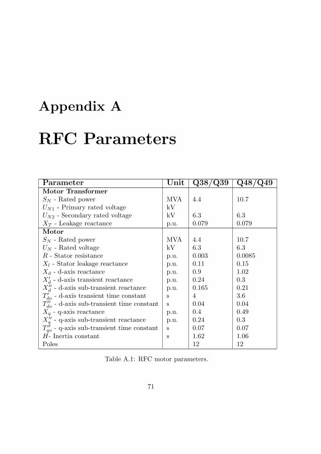
Appendix A
RFC Parameters
Parameter Unit Q38/Q39 Q48/Q49Motor TransformerSN - Rated power MVA 4.4 10.7UN1 - Primary rated voltage kVUN2 - Secondary rated voltage kV 6.3 6.3XT - Leakage reactance p.u. 0.079 0.079MotorSN - Rated power MVA 4.4 10.7UN - Rated voltage kV 6.3 6.3R - Stator resistance p.u. 0.003 0.0085Xl - Stator leakage reactance p.u. 0.11 0.15Xd - d-axis reactance p.u. 0.9 1.02X ′d - d-axis transient reactance p.u. 0.24 0.3
X ′′d - d-axis sub-transient reactance p.u. 0.165 0.21
T ′do - d-axis transient time constant s 4 3.6T ′′do - d-axis sub-transient time constant s 0.04 0.04Xq - q-axis reactance p.u. 0.4 0.49X ′′q - q-axis sub-transient reactance p.u. 0.24 0.3
T ′′qo - q-axis sub-transient time constant s 0.07 0.07H- Inertia constant s 1.62 1.06Poles 12 12
Table A.1: RFC motor parameters.
71
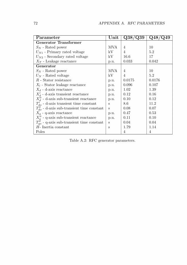
72 APPENDIX A. RFC PARAMETERS
Parameter Unit Q38/Q39 Q48/Q49Generator TransformerSN - Rated power MVA 4 10UN1 - Primary rated voltage kV 4 5.2UN2 - Secondary rated voltage kV 16.6 17XT - Leakage reactance p.u. 0.033 0.042GeneratorSN - Rated power MVA 4 10UN - Rated voltage kV 4 5.2R - Stator resistance p.u. 0.0175 0.0176Xl - Stator leakage reactance p.u. 0.096 0.107Xd - d-axis reactance p.u. 1.02 1.39X ′d - d-axis transient reactance p.u. 0.12 0.16
X ′′d - d-axis sub-transient reactance p.u. 0.10 0.12
T ′do - d-axis transient time constant s 8.6 11.2T ′′do - d-axis sub-transient time constant s 0.08 0.07Xq - q-axis reactance p.u. 0.47 0.53X ′′q - q-axis sub-transient reactance p.u. 0.11 0.10
T ′′qo - q-axis sub-transient time constant s 0.04 0.04H- Inertia constant s 1.79 1.14Poles 4 4
Table A.2: RFC generator parameters.
Part IV
Publications
73

Paper I:
A rotary frequency converter model for electrome-
chanical transient studies of 1623 Hz railway sys-
tems.
75

Paper II
A simplified static frequency converter model for
electromechanical transient stability studies of 1623 Hz
railways.
87


Paper III
Transient stability of rotary frequency converter
fed low frequency railway grids: The impact of
different grid impedances and converter station
configurations.
105

Paper IV
Transient stability of a rotary frequency converter
fed railway, interconnected with a parallel low-
frequency high voltage transmission system.
117

Paper V
Impact of reduced share of rotary frequency con-
verters in a low frequency synchronous railway
grid: A transient stability study.
129

Paper VI
Further studies of the transient stability of rotary
frequency converter fed low frequency AC railway
with a high voltage transmission.
141

Paper VII
Evaluating a constant-current load model through
comparative transient stability case studies of a
synchronous-synchronous rotary frequency con-
verter fed railway.
155

Paper VIII
Challenges with increased share of power elec-
tronic generation in railway power supply sys-
tems.
167

Stability of Low-Frequency AC RailwaysModels and Transient Stability
John Laury
Electric Power Engineering
Department of Engineering Sciences and MathematicsDivision of Energy Science
ISSN 1402-1544ISBN 978-91-7790-292-8 (print)ISBN 978-91-7790-293-5 (pdf)
Luleå University of Technology 2019
DOCTORA L T H E S I S
John Laury Stability of Low-Frequency A
C R
ailways - M
odels and Transient Stability