ISS - KICP Workshops
43
JEM-EUSO focal surface electronics M. Casolino RIKEN INFN & University of Rome Tor Vergata
Transcript of ISS - KICP Workshops

JEM-EUSO focal surface electronics
M. Casolino
RIKEN INFN & University of Rome Tor Vergata

JEM-EUSO(2017)
(2013)
(2014)
JEM-EUSO (2017)
1. Ground-EUSO: Test at Telescope Array site. (2013)
2. EUSO-BALLOON 3 Balloon flights from Canada (French Space Agency CNES) 2014-
The EUSO program
2

3

Conceptual view of the telescope
4

Optical system protoype
2.65 m
1.5 m
large diameter Fresnel lenses manufactured in Japan and tested in the US at the University of Alabama (Huntsville) and at MSFC (NASA)
Tested performances meet already the requirements (or are close to it)
Spot size is 2.5 mm!
5


Image is inverted (Seen from inside)
ELS accelerator building
Control room

3rd groove surface roughness measurement
Electrical noise
RMS surface roughness requirement : < 0.0200um (=20nm)
Lens precision: 20 nm

Focal Surface Mechanics
Volume for Electronics (167 x 128 x 130)
PDM Frame
EC Base64 channel MAPMT
FS Structure – Front view
Three element support, (note sphericity)
Photo Detector Module 2304 channels
137 PDMs in the FS – 315 kchannels
2.5 m

FS Shape
10

Simulations by K. Shinozaki
Sicily seen from EUSO •Simulation of UV light•Environmental monitoring
11

Simulations by K. Shinozaki
Sicily seen from EUSO •Simulation of UV light•Environmental monitoring
10^20 eV shower
11

UltraViolet fluorescence emission
Cherenkov light
Time
250 µs
Signal of a proton shower (1020eV, 60 deg)
12

Mechanical structure of the
13

PMT development• Collaboration with Hamamatsu
M64• Reduction of size• Improvement of Quantum
efficiency• Improvement of uniformity of
response • Each of the 137 PDM boxes
houses 36 PMTs, 64 channels each
Miniaturization of dynodes
Hamamatsu PhotonicsUltra Bialkali ZB0765 Average: (24.4 ± 1.8)%
UV Filter 14

MAPMT
15
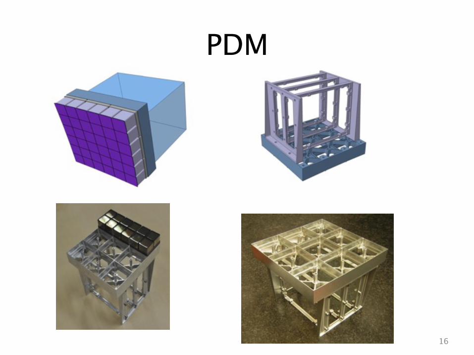
PDM
16

5760 PMT – 300kch
1440 PMT
143 PDM
20 PDM
1 MPU
•300 Kchannels•Strongly parallel and hyerarchical structure•Intrinsic redundancy
36 channel UBA PMT

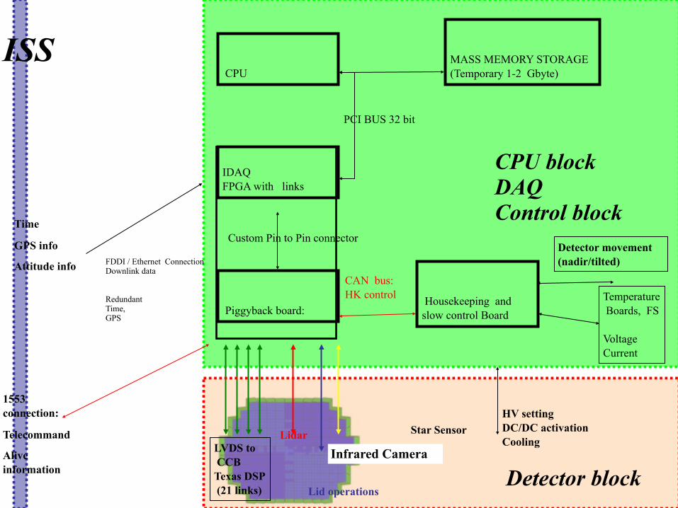
ISS
Detector block
CPU blockDAQ Control block

ISS
LVDS to CCBTexas DSP (21 links)
Lidar
Lid operations
Infrared Camera
Detector block
CPU blockDAQ Control block
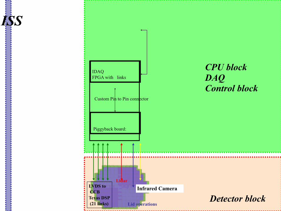
ISS
LVDS to CCBTexas DSP (21 links)
Lidar
Lid operations
Infrared Camera
Piggyback board:
Custom Pin to Pin connector
IDAQ FPGA with links
Detector block
CPU blockDAQ Control block

CPUISS
LVDS to CCBTexas DSP (21 links)
Lidar
Lid operations
Infrared Camera
Piggyback board:
Custom Pin to Pin connector
IDAQ FPGA with links
Detector block
CPU blockDAQ Control block

CPUISS
PCI BUS 32 bit
MASS MEMORY STORAGE(Temporary 1-2 Gbyte)
LVDS to CCBTexas DSP (21 links)
Lidar
Lid operations
Infrared Camera
Piggyback board:
Custom Pin to Pin connector
IDAQ FPGA with links
Detector block
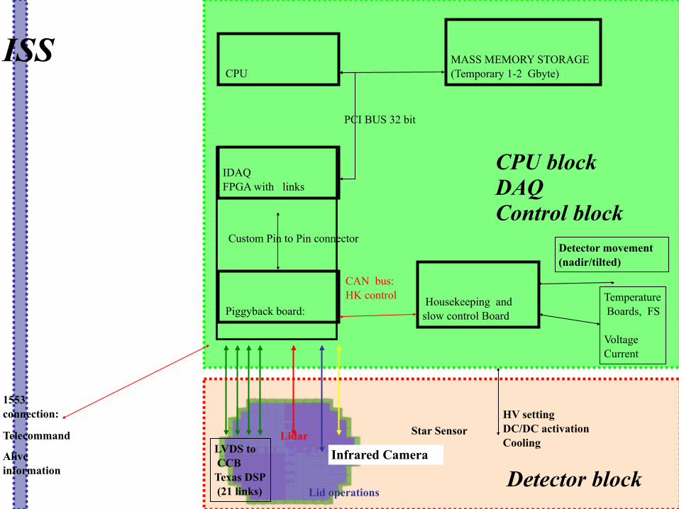
CPU blockDAQ Control block

CPU
CAN bus: HK control Housekeeping and
slow control Board
ISS
PCI BUS 32 bit
MASS MEMORY STORAGE(Temporary 1-2 Gbyte)
LVDS to CCBTexas DSP (21 links)
Lidar
Lid operations
Infrared Camera
Piggyback board:
Custom Pin to Pin connector
IDAQ FPGA with links
Detector block
CPU blockDAQ Control block

CPU
CAN bus: HK control Housekeeping and
slow control Board
ISS
PCI BUS 32 bit
MASS MEMORY STORAGE(Temporary 1-2 Gbyte)
LVDS to CCBTexas DSP (21 links)
Lidar
Lid operations
Infrared Camera
Temperature Boards, FS
VoltageCurrent
Detector movement (nadir/tilted)
Piggyback board:
Custom Pin to Pin connector
IDAQ FPGA with links
Detector block
CPU blockDAQ Control block

CPU
CAN bus: HK control Housekeeping and
slow control Board
ISS
PCI BUS 32 bit
MASS MEMORY STORAGE(Temporary 1-2 Gbyte)
LVDS to CCBTexas DSP (21 links)
Lidar
Lid operations
Infrared Camera
HV setting DC/DC activationCooling
Star Sensor
Temperature Boards, FS
VoltageCurrent
Detector movement (nadir/tilted)
Piggyback board:
Custom Pin to Pin connector
IDAQ FPGA with links
Detector block
CPU blockDAQ Control block
1553 connection:
Telecommand
Alive information
FDDI / Ethernet ConnectionDownlink data Redundant Time, GPS
Time
GPS info
Attitude info

CPU
CAN bus: HK control Housekeeping and
slow control Board
ISS
PCI BUS 32 bit
MASS MEMORY STORAGE(Temporary 1-2 Gbyte)
Downlink to ISSStorage on Hard Disk
LVDS to CCBTexas DSP (21 links)
Lidar
Lid operations
Infrared Camera
HV setting DC/DC activationCooling
Star Sensor
Temperature Boards, FS
VoltageCurrent
Detector movement (nadir/tilted)
Piggyback board:
Custom Pin to Pin connector
IDAQ FPGA with links
Detector block
CPU blockDAQ Control block
1553 connection:
Telecommand
Alive information
FDDI / Ethernet ConnectionDownlink data Redundant Time, GPS
Time
GPS info
Attitude info

JEM-EUSO DAQ – CURRENT Electronic System scheme
FEE
ASIC+FPGA
Count
137 PDM Control Board
FPGA
Track Trigger
Cluster Control Board
FPGA
Fine Trigger
CPU
TelemetryInterfaces
137 Boards 20 Board
1CCB1PDM9EC
140 GB/s (FS)
PhotoDetector Modules
3*10-3 compression
1 PDM 36 x 64 channels
PMT
1936 36-3lay 6
1
1
1
36
300kch1,287 EC
2 Board
137 PDM20 CCB
1 CPU1 CLOCK
1GPS½ Housekeeping
storage
137 PDM New design
10-3 compression 297 kbit/s 3 Gbyte/day (downlink)
Storage on SSD will give factor 3-5, up to 10 Gbyte/dayReturn with Soyuz or Dragon

TA EUSO DAQ – CURRENT Electronic System scheme
FEE
ASIC+FPGA
Count
PDM Control Board
FPGA
Track Trigger
Cluster Control Board
FPGA
Fine Trigger
CPUSpacewire
Clock Board GPS
Data StorageSoftware
TelemetryInterfaces
1 Boards
1CCB1PDM9EC
1GB/s (FS)
PhotoDetector Modules
4*10-3 compression no compression
1 PDM 36 x 64 channels
PMT
2036 36-3lay 6
1
1
1
36
2304ch9 EC
2 Board
1 PDM1 EC BOARD
2 PMT 1 CCB
1 CPU1 CLOCK
1GPS½ Housekeeping
storage
3Mbyte/s 10 Gbyte/hour
Most dataStored on SSD 17 GB/hour (save all stream)

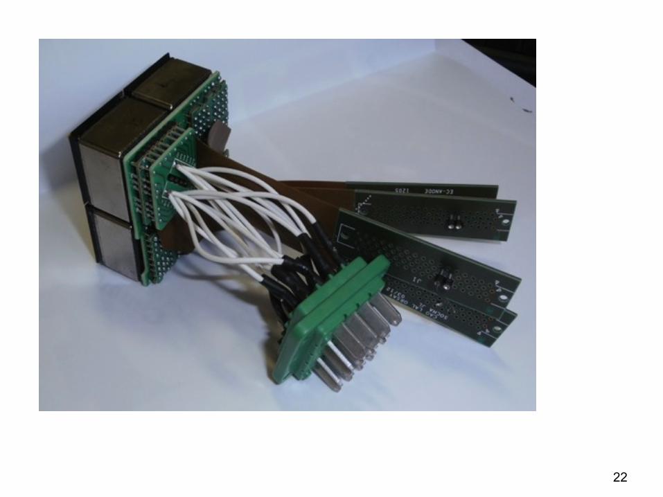
• 3 different PCBs:
• First one (EC DYNODE board) allows to reroute half of the dynodes of 1 MAPMT so that they are aligned perpendicularly to the others. It covers the 4 MAPMTs.
• Second one (EC ANODE board) covers one MAPMT but has dimensions reduced allowing a flex pcb to get out. It is used to collect signal from the anodes and send them to the ASICs.
• Third one (EC HV board) covers one MAPMT. It welcomes the dynodes and supplies the HV (up to 1000 V) to the EC-dynode board which transmits it to the 4 MAPMTs.
Per EC unit:• 1 EC-DYNODE board• 4 EC-ANODE boards• 1 EC-HV boards
UV filter
MAPMTMAPMT MAPMT
Flexible pcb toward EC-back
HV cables toward HV box21
Reminder: EC-front unit
Central column
22

23
HV (Resistor)
PDM
EC-ASIC 1 of 6
EC UNIT1 of 9
4 MAPMT256 channels

24
6 EC-ASICS, each with 3+3 Asics

25
LV PS HK CPU
storage
CCB CLK GPS
PDM EC-ASIC EC-UNIT

26
Laser Light

27
Spot seen in the focal point

28
Real-time On board calibration
Individual channel
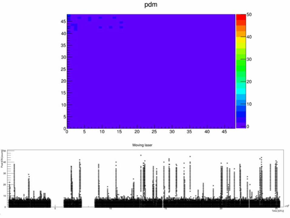
29

CNES approved balloon missionFirst flight 2014

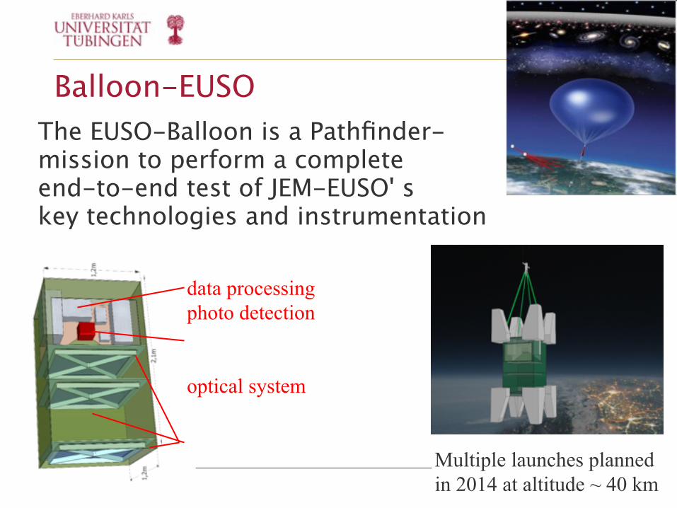
Balloon-EUSO The EUSO-Balloon is a Pathfinder-mission to perform a complete end-to-end test of JEM-EUSO' s key technologies and instrumentation
data processingphoto detection
optical system
Multiple launches plannedin 2014 at altitude ~ 40 km

![ALTEA: 2012 radiation measurements in the ISS - …wrmiss.org/workshops/eighteenth/Narici.pdf · ALTEA: 2012 radiation measurements in the ISS L ... (cm^2 sr s )] Shielding (Poles](https://static.fdocuments.us/doc/165x107/5b09cad17f8b9a3d018e3bed/altea-2012-radiation-measurements-in-the-iss-2012-radiation-measurements-in-the.jpg)