Networking 101. OSI Reference Model Data Header Header Header.
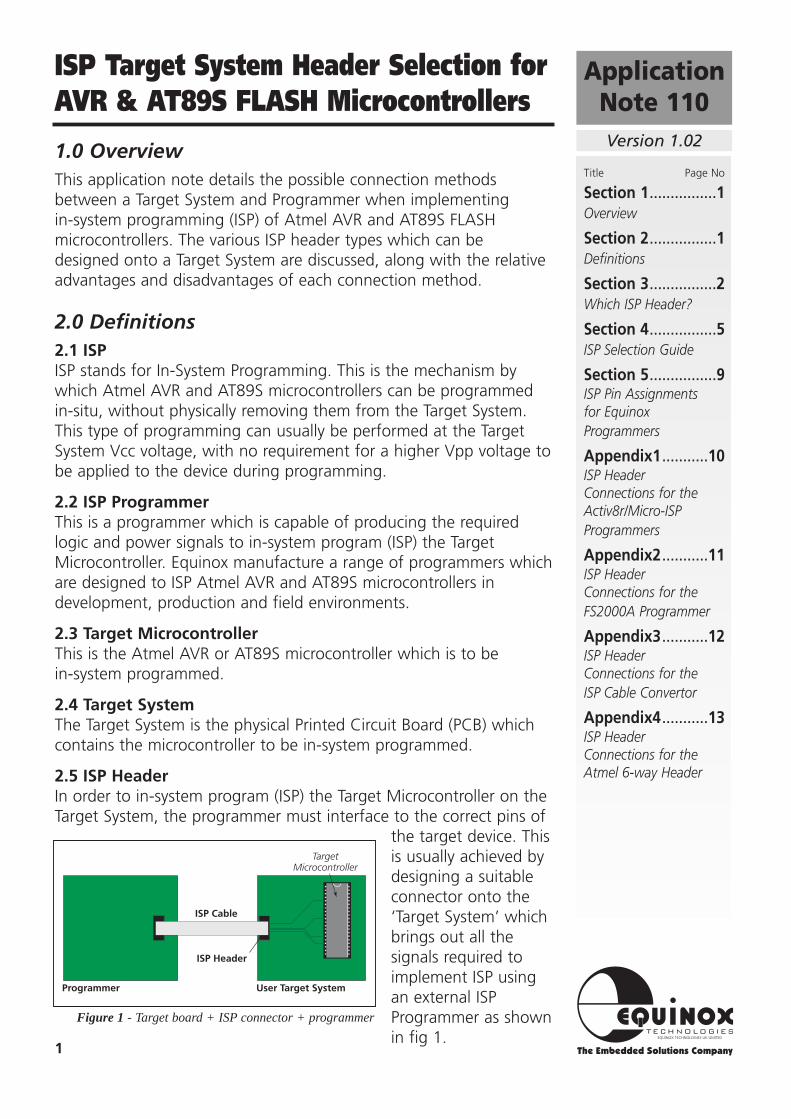
1.0 OverviewThis application note details the possible connection methodsbetween a Target System and Programmer when implementingin-system programming (ISP) of Atmel AVR and AT89S FLASHmicrocontrollers. The various ISP header types which can bedesigned onto a Target System are discussed, along with the relativeadvantages and disadvantages of each connection method.
2.0 Definitions2.1 ISPISP stands for In-System Programming. This is the mechanism bywhich Atmel AVR and AT89S microcontrollers can be programmedin-situ, without physically removing them from the Target System.This type of programming can usually be performed at the TargetSystem Vcc voltage, with no requirement for a higher Vpp voltage tobe applied to the device during programming.
2.2 ISP ProgrammerThis is a programmer which is capable of producing the requiredlogic and power signals to in-system program (ISP) the TargetMicrocontroller. Equinox manufacture a range of programmers whichare designed to ISP Atmel AVR and AT89S microcontrollers indevelopment, production and field environments.
2.3 Target MicrocontrollerThis is the Atmel AVR or AT89S microcontroller which is to bein-system programmed.
2.4 Target SystemThe Target System is the physical Printed Circuit Board (PCB) whichcontains the microcontroller to be in-system programmed.
2.5 ISP HeaderIn order to in-system program (ISP) the Target Microcontroller on theTarget System, the programmer must interface to the correct pins of
the target device. Thisis usually achieved bydesigning a suitableconnector onto the‘Target System’ whichbrings out all thesignals required toimplement ISP usingan external ISPProgrammer as shownin fig 1.
ApplicationNote 110
ISP Target System Header Selection forAVR & AT89S FLASH Microcontrollers
Version 1.02
User Target System
TargetMicrocontroller
ISP Cable
Programmer
ISP Header
1
Figure 1 - Target board + ISP connector + programmer
Title Page No
Section 1................1Overview
Section 2................1Definitions
Section 3................2Which ISP Header?
Section 4................5ISP Selection Guide
Section 5................9ISP Pin Assignmentsfor EquinoxProgrammers
Appendix1...........10ISP HeaderConnections for theActiv8r/Micro-ISPProgrammers
Appendix2...........11ISP HeaderConnections for theFS2000A Programmer
Appendix3...........12ISP HeaderConnections for theISP Cable Convertor
Appendix4...........13ISP HeaderConnections for theAtmel 6-way Header
3.0 Which ISP Header? The choice of interconnection method between the Target Systemand the ISP Programmer depends on many factors including thechosen ISP programmer, Target System space requirements, extra ISPfunctionality required and the quantity/throughput of Target Systemsto be programmed. There is also now a trend to allow field servicepersonnel and even customers to remotely upgrade the productfirmware in the field.
The factors influencing the selection of the ISP Header aredetailed below:
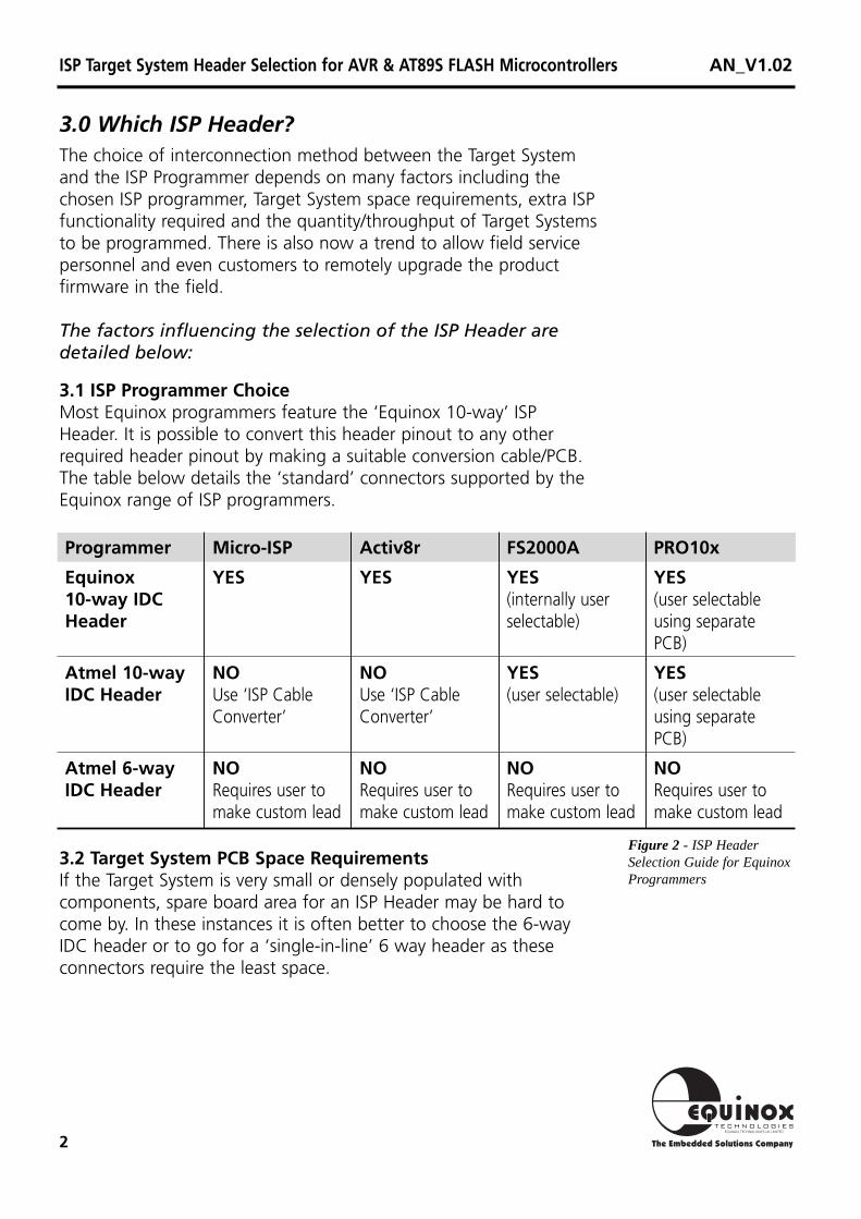
3.1 ISP Programmer ChoiceMost Equinox programmers feature the ‘Equinox 10-way’ ISPHeader. It is possible to convert this header pinout to any otherrequired header pinout by making a suitable conversion cable/PCB.The table below details the ‘standard’ connectors supported by theEquinox range of ISP programmers.
2
Programmer
Equinox10-way IDC Header
Atmel 10-way IDC Header
Atmel 6-way IDC Header
Micro-ISP
YES
NOUse ‘ISP CableConverter’
NORequires user tomake custom lead
Activ8r
YES
NOUse ‘ISP CableConverter’
NORequires user tomake custom lead
FS2000A
YES(internally userselectable)
YES(user selectable)
NORequires user tomake custom lead
PRO10x
YES(user selectableusing separatePCB)
YES(user selectableusing separatePCB)
NORequires user tomake custom lead
3.2 Target System PCB Space RequirementsIf the Target System is very small or densely populated withcomponents, spare board area for an ISP Header may be hard tocome by. In these instances it is often better to choose the 6-wayIDC header or to go for a ‘single-in-line’ 6 way header as theseconnectors require the least space.
Figure 2 - ISPHeaderSelection Guide for EquinoxProgrammers
ISP Target System Header Selection for AVR & AT89S FLASH Microcontrollers AN_V1.02

3
3.3 Signals required for the specific microcontroller beingprogrammedMost Atmel AVR and AT89S microcontrollers require only sixconnections to implement basic ISP programming as follows: Vcc,GND, MOSI, MISO, SCK and RESET. However, there are certaininstances where more pins are required to implement extrafunctionality. The extra pins are SS(Slave Select), SCK2 (Serial Clock2), PROG_LED and a second GROUND connection. The function ofthese pins is detailed in section 4.
Figure 3 - TypicalConnections for ISPProgramming.
ISP Target System Header Selection for AVR & AT89S FLASH Microcontrollers AN_V1.02
TargetSystem
Target Ground
PC
Common earth point
PC Ground
ISP Programmer
VccRSTMOSIMISOSCKGND
ISP Header
ISP Cable
4
TargetConnections
Status LED's
Adaptor Module
Bed of NailsTest Fixture
Target PCB
ISP Cable
Programmer
Test Pin
PCB
SolderConnection
To theProgrammer
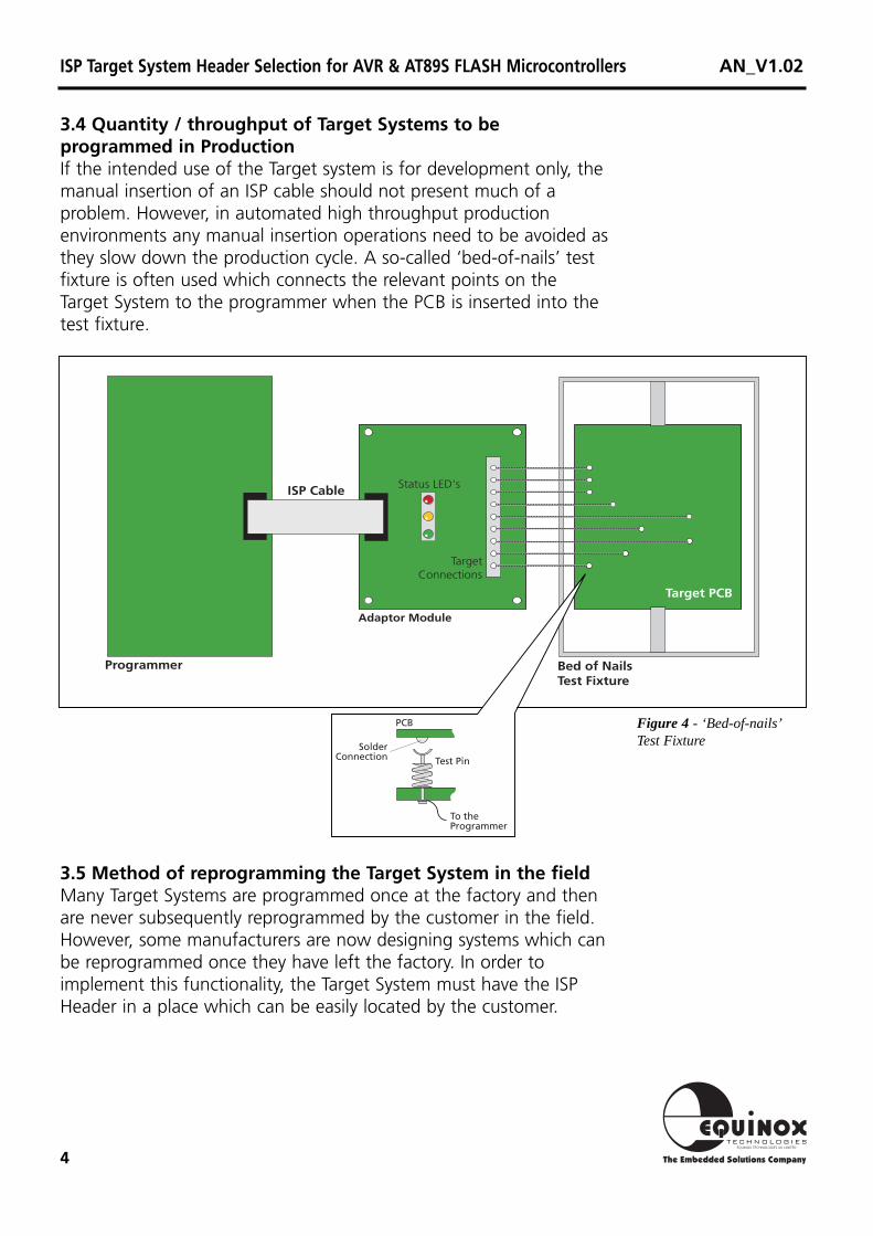
3.4 Quantity / throughput of Target Systems to beprogrammed in ProductionIf the intended use of the Target system is for development only, themanual insertion of an ISP cable should not present much of aproblem. However, in automated high throughput productionenvironments any manual insertion operations need to be avoided asthey slow down the production cycle. A so-called ‘bed-of-nails’ testfixture is often used which connects the relevant points on theTarget System to the programmer when the PCB is inserted into thetest fixture.
3.5 Method of reprogramming the Target System in the fieldMany Target Systems are programmed once at the factory and thenare never subsequently reprogrammed by the customer in the field.However, some manufacturers are now designing systems which canbe reprogrammed once they have left the factory. In order toimplement this functionality, the Target System must have the ISPHeader in a place which can be easily located by the customer.
Figure 4 - ‘Bed-of-nails’Test Fixture
ISP Target System Header Selection for AVR & AT89S FLASH Microcontrollers AN_V1.02

5
4.0 ISP Selection GuideThe relevant advantages and disadvantages of each header type areshown in fig. 5. It is also possible to implement a custom ISPconnector by using an interface cable or PCB between theprogrammer and the header.
ISP Connection type
Equinox10-way IDC Header
Atmel 10-way IDC Header
Atmel 6-way IDC Header
6-way SIL Header
Bed-of-nails
Advantages
1 Extra serial clock signal availableon SCK2 for clocking AVRdevices
2 Target LED control pin available(Micro-ISP only)
3 Second GROUND pin may beused by the target system tosense presence of theprogrammer.
4 IDC plug and socket arepolarised to prevent incorrectinsertion of the ISP cable
5 Used on all Equinox targetsystems and in all Equinoxapplication notes
1 Widely used on the AtmelSTK100, 200 and 300 systems
2 IDC plug and socket arepolarised to prevent incorrectinsertion of the ISP cable
1 Small physical PCB footprint2 Ideal for volume production
where board space is apremium.
1 Simple to add to existing PCBdesign
2 Easier alignment of bed-of-nailstest pins
1 No PCB area taken up by adedicated connector
2 Ideal for automated testhandlers
Disadvantages
1 Larger PCB footprint than 6-wayheader.
2 Not compatible with the AtmelSTK100, 200, 300 systems.
1 Larger PCB footprint than 6-wayheader.
2 No extra lines for SCK2 or LEDcontrol.
1 No extra lines available for SCK2or LED control.
2 6-way non-reversible connectormay be hard to source.
1 No polarisation of ISPheader/plug available
1 ISP connector is not available ifthe product is to bereprogrammed in the field.
2 ISP cable lengths are oftenlonger.
3 Board may require special designto bring out ISP connections.
Figure 5 - ISPConnection Type - Advantage/Disadvantage Guide
ISP Target System Header Selection for AVR & AT89S FLASH Microcontrollers AN_V1.02
6
ISP Target System Header Selection for AVR & AT89S FLASH Microcontrollers AN_V1.02
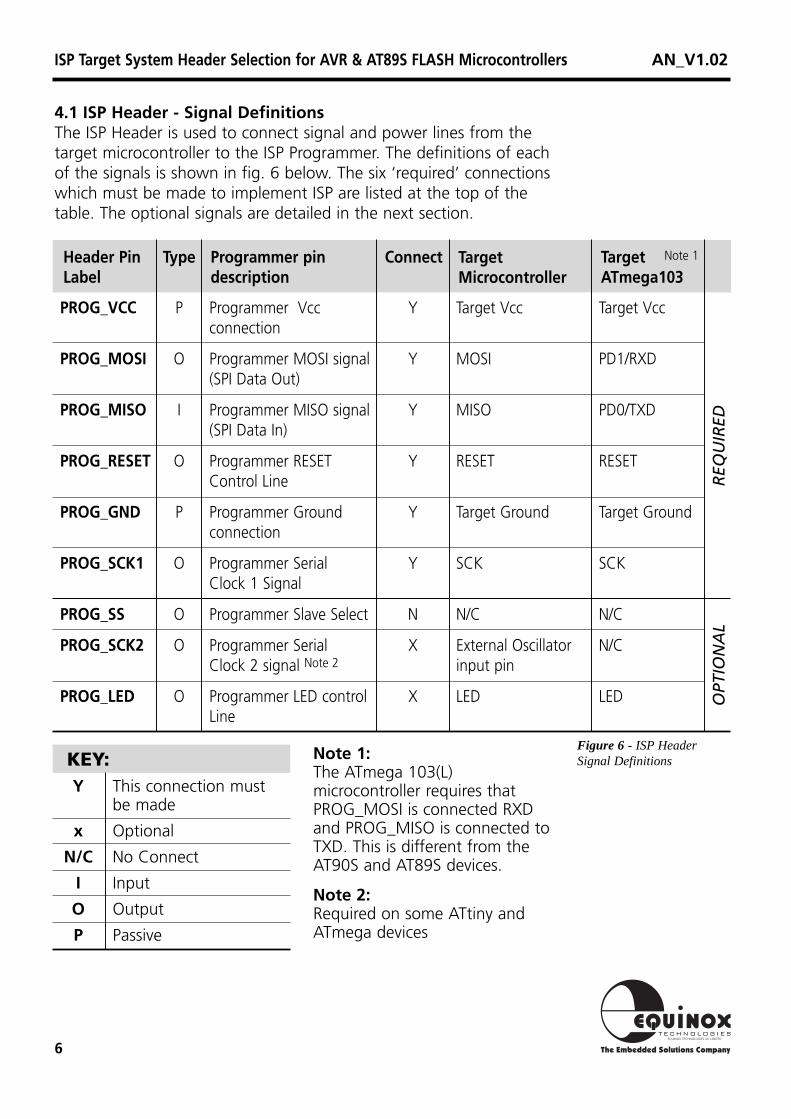
4.1 ISP Header - Signal DefinitionsThe ISP Header is used to connect signal and power lines from thetarget microcontroller to the ISP Programmer. The definitions of eachof the signals is shown in fig. 6 below. The six ‘required’ connectionswhich must be made to implement ISP are listed at the top of thetable. The optional signals are detailed in the next section.
Header PinLabel
Programmer pindescription
Connect TargetMicrocontroller
TargetATmega103
Type
PROG_VCC
PROG_MOSI
PROG_MISO
PROG_RESET
PROG_GND
PROG_SCK1
PROG_SS
PROG_SCK2
PROG_LED
Target Vcc
PD1/RXD
PD0/TXD
RESET
Target Ground
SCK
N/C
N/C
LED
Target Vcc
MOSI
MISO
RESET
Target Ground
SCK
N/C
External Oscillatorinput pin
LED
Y
Y
Y
Y
Y
Y
N
X
X
Programmer Vccconnection
Programmer MOSI signal(SPI Data Out)
Programmer MISO signal(SPI Data In)
Programmer RESET Control Line
Programmer Groundconnection
Programmer SerialClock 1 Signal
Programmer Slave Select
Programmer SerialClock 2 signal Note 2
Programmer LED control Line
P
O
I
O
P
O
O
O
O
KEY:Y This connection must
be made
x Optional
N/C No Connect
I Input
O Output
P Passive
Figure 6 - ISPHeaderSignal Definitions
OPT
ION
AL
REQ
UIR
ED
Note 1:The ATmega 103(L)microcontroller requires thatPROG_MOSI is connected RXDand PROG_MISO is connected toTXD. This is different from theAT90S and AT89S devices.
Note 2:Required on some ATtiny andATmega devices
Note 1
7
4.2 Optional ISP SignalsThe following signal lines are not absolutely necessary to implementISP but should be taken into consideration at the PCB design stage.These signal lines may not be present on all Equinox programmers.
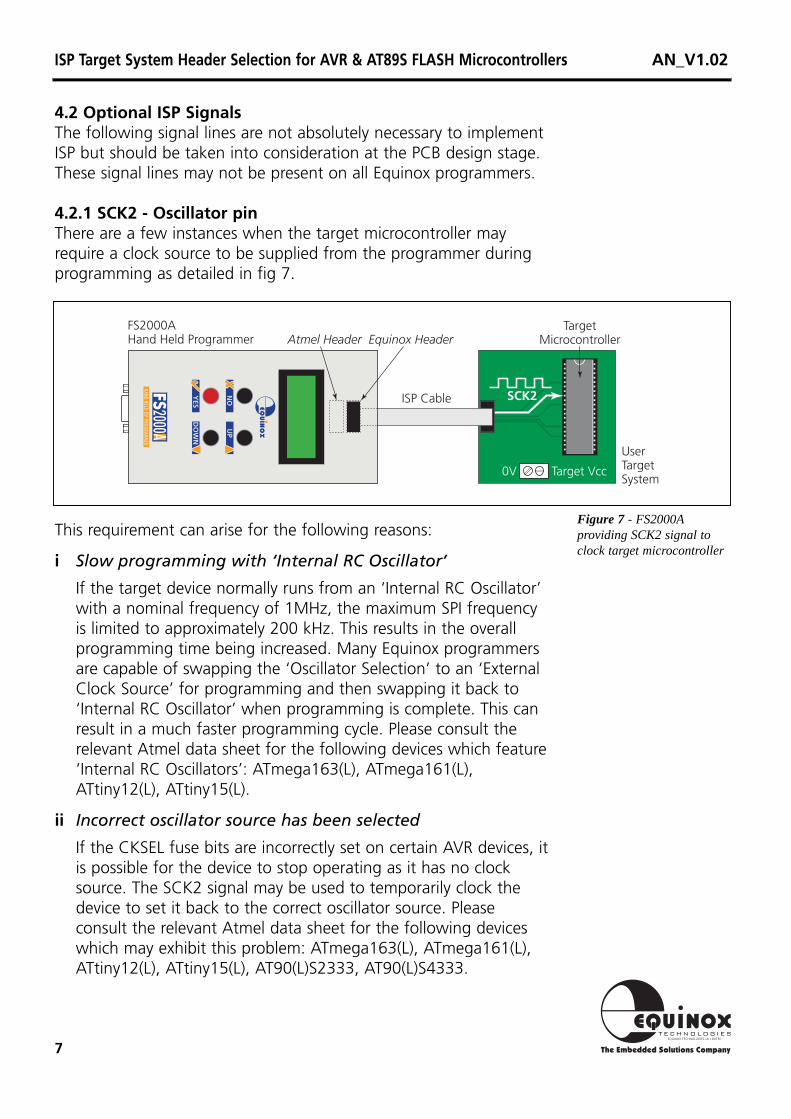
4.2.1 SCK2 - Oscillator pinThere are a few instances when the target microcontroller mayrequire a clock source to be supplied from the programmer duringprogramming as detailed in fig 7.
UserTargetSystem
TargetMicrocontroller
0V Target Vcc
FS2000AHand Held Programmer
ISP Cable
Atmel Header Equinox Header
SCK2
Figure 7 - FS2000Aproviding SCK2 signal toclock target microcontroller
This requirement can arise for the following reasons:
i Slow programming with ‘Internal RC Oscillator’
If the target device normally runs from an ‘Internal RC Oscillator’with a nominal frequency of 1MHz, the maximum SPI frequencyis limited to approximately 200 kHz. This results in the overallprogramming time being increased. Many Equinox programmersare capable of swapping the ‘Oscillator Selection’ to an ‘ExternalClock Source’ for programming and then swapping it back to‘Internal RC Oscillator’ when programming is complete. This canresult in a much faster programming cycle. Please consult therelevant Atmel data sheet for the following devices which feature‘Internal RC Oscillators’: ATmega163(L), ATmega161(L),ATtiny12(L), ATtiny15(L).
ii Incorrect oscillator source has been selected
If the CKSEL fuse bits are incorrectly set on certain AVR devices, itis possible for the device to stop operating as it has no clocksource. The SCK2 signal may be used to temporarily clock thedevice to set it back to the correct oscillator source. Pleaseconsult the relevant Atmel data sheet for the following deviceswhich may exhibit this problem: ATmega163(L), ATmega161(L),ATtiny12(L), ATtiny15(L), AT90(L)S2333, AT90(L)S4333.
ISP Target System Header Selection for AVR & AT89S FLASH Microcontrollers AN_V1.02
8
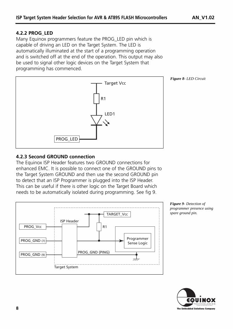
4.2.2 PROG_LEDMany Equinox programmers feature the PROG_LED pin which iscapable of driving an LED on the Target System. The LED isautomatically illuminated at the start of a programming operationand is switched off at the end of the operation. This output may alsobe used to signal other logic devices on the Target System thatprogramming has commenced.
R1
LED1
Target Vcc
PROG_LED
4.2.3 Second GROUND connectionThe Equinox ISP Header features two GROUND connections forenhanced EMC. It is possible to connect one of the GROUND pins tothe Target System GROUND and then use the second GROUND pinto detect that an ISP Programmer is plugged into the ISP Header.This can be useful if there is other logic on the Target Board whichneeds to be automatically isolated during programming. See fig 9.
Figure 8- LED Circuit
Figure 9- Detection ofprogrammer presence usingspare ground pin.
R1
ISP Header
ProgrammerSense Logic
PROG_GND (PING)PROG_GND (9)
PROG_GND (7)
PROG_Vcc
Target System
TARGET_Vcc
ISP Target System Header Selection for AVR & AT89S FLASH Microcontrollers AN_V1.02
9
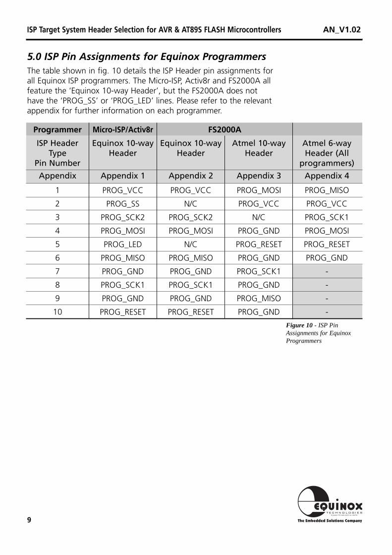
5.0 ISP Pin Assignments for Equinox ProgrammersThe table shown in fig. 10 details the ISP Header pin assignments forall Equinox ISP programmers. The Micro-ISP, Activ8r and FS2000A allfeature the ‘Equinox 10-way Header’, but the FS2000A does nothave the ‘PROG_SS’ or ‘PROG_LED’ lines. Please refer to the relevantappendix for further information on each programmer.
Programmer
ISP HeaderType
Pin Number
Appendix
Atmel 6-wayHeader (All
programmers)
Appendix 4
Atmel 10-wayHeader
Appendix 3
Equinox 10-wayHeader
Appendix 2
FS2000AMicro-ISP/Activ8r
Equinox 10-wayHeader
Appendix 1
1
2
3
4
5
6
7
8
9
10
PROG_MISO
PROG_VCC
PROG_SCK1
PROG_MOSI
PROG_RESET
PROG_GND
-
-
-
-
PROG_MOSI
PROG_VCC
N/C
PROG_GND
PROG_RESET
PROG_GND
PROG_SCK1
PROG_GND
PROG_MISO
PROG_GND
PROG_VCC
N/C
PROG_SCK2
PROG_MOSI
N/C
PROG_MISO
PROG_GND
PROG_SCK1
PROG_GND
PROG_RESET
PROG_VCC
PROG_SS
PROG_SCK2
PROG_MOSI
PROG_LED
PROG_MISO
PROG_GND
PROG_SCK1
PROG_GND
PROG_RESET
Figure 10 - ISPPinAssignments for EquinoxProgrammers
ISP Target System Header Selection for AVR & AT89S FLASH Microcontrollers AN_V1.02

10
Appendix 1 - ISP Header Connections for Activ8r/Micro-ISP Programmers
EquinoxISP CableTop View
Equinox ISP CableBottom View
10-way Headeron User Target System
Pin 1
Pin 1
Red stripeindicatesPin 1
Figure 1 indicates the position of Pin 1 forboth the ISP cable supplied and a 10-wayIDC header situated on the target system.
Figure 2 indicates the pinout required fortarget system IDC header when using eithera Micro-ISP or Activ8r programmer.
UserTargetSystem
TargetMicrocontroller
0V Target Vcc
ISP Cable
Micro-ISPProgrammer
UserTargetSystem
TargetMicrocontroller
0V Target Vcc
ISP Cable
Activ8r Programmer
2
3
5
7 8
6
4
9
1
10
PROG_SS
PROG_SCK1
PROG_MOSI
PROG_RESET
PROG_MISO
PROG_GND
PROG_SCK2
PROG_LED
PROG_Vcc
PROG_GND
Figure 2
Figure 1
Figure 3
Figure 4
ISP Target System Header Selection for AVR & AT89S FLASH Microcontrollers AN_V1.02

11
2
3
5
7 8
6
4
9
1
10
PROG_Vcc
PROG_GND
PROG_GND
PROG_GND
PROG_GND
PROG_MISO
N/C
PROG_RESET
PROG_MOSI
PROG_SCK
Appendix 2 - ISP Header Connections for the FS2000A Programmer
Equinox 10-way headerAtmel 10-way header
EquinoxISP CableTop View
Equinox ISP CableBottom View
10-way Headeron User Target System
Pin 1
Pin 1
Red stripeindicatesPin 1
Figure 1 indicates the position of Pin 1 forboth the ISP cable supplied and a 10-wayIDC header situated on the target system.
Figures 2 & 3 indicate the pinouts requiredfor target system 10-way IDC header whenusing either an Equinox or Atmel 10-wayHeaders
UserTargetSystem
TargetMicrocontroller
0V Target Vcc
FS2000APortable ISP Programmer
ISP Cable
Atmel Header Equinox Header
2
3
5
7 8
6
4
9
1
10
N/C
PROG_SCK1
PROG_MOSI
PROG_RESET
PROG_MISO
PROG_GND
PROG_SCK2
N/C
PROG_Vcc
PROG_GND
Figure 2
Figure 1
Figure 3
Figure 4
ISP Target System Header Selection for AVR & AT89S FLASH Microcontrollers AN_V1.02

12
Appendix 3 - ISP Header Connections for the ISP Cable Convertor
Figure 1 indicates the position of Pin 1 forboth the ISP cable supplied and a 10-wayIDC header situated the cable convertor.
The pinout for the Equinox 10-way headeron the ISP cable convertor is shown infigure 3.
Figure 4 shows the pinout used for theAtmel 10-way header on the user targetsystem. Using this header will require theuse of the ISP Cable Convertor indicated infigure 4.
EquinoxISP CableTop View
Equinox ISP CableBottom View
10-way Headeron User Target System
Pin 1
Pin 1
Red stripeindicatesPin 1
UserTargetSystem
TargetMicrocontroller
0V Target Vcc
ISP CableISP Cable
Micro-ISPProgrammer ISP Cable
Convertor
2
3
5
7 8
6
4
9
1
10
PROG_Vcc
PROG_GND
PROG_GND
PROG_GND
PROG_GND
PROG_MISO
N/C
PROG_RESET
PROG_MOSI
PROG_SCK
2
3
5
7 8
6
4
9
1
10
N/C
PROG_SCK1
PROG_MOSI
PROG_RESET
PROG_MISO
PROG_GND
PROG_SCK2
N/C
PROG_Vcc
PROG_GND
Equinox 10-way header Atmel 10-way header
Figure 2
Figure 1
Figure 3 Figure 4
ISP Target System Header Selection for AVR & AT89S FLASH Microcontrollers AN_V1.02
13
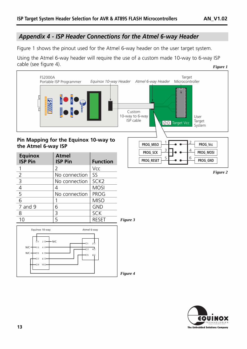
1 2 Vcc2 No connection SS3 No connection SCK24 4 MOSI5 No connection PROG6 1 MISO7 and 9 6 GND8 3 SCK10 5 RESET
EquinoxISP Pin
AtmelISP Pin Function
Figure 1 shows the pinout used for the Atmel 6-way header on the user target system.
Using the Atmel 6-way header will require the use of a custom made 10-way to 6-way ISPcable (see figure 4).
Appendix 4 - ISP Header Connections for the Atmel 6-way Header
UserTargetSystem
TargetMicrocontroller
0V Target Vcc
FS2000APortable ISP Programmer
Custom10-way to 6-way
ISP cable
Equinox 10-way Header Atmel 6-way Header
1 2
3 4
5 6
7 8
9 10
1 2
3 4
5 6
Equinox 10-way Atmel 6-way
N/C
N/C
N/C
2
3
5 6
4
1 PROG_Vcc
PROG_MOSI
PROG_GND
PROG_SCK
PROG_RESET
PROG_MISOPin Mapping for the Equinox 10-way tothe Atmel 6-way ISP
Figure 2
Figure 1
Figure 3
Figure 4
ISP Target System Header Selection for AVR & AT89S FLASH Microcontrollers AN_V1.02