ISOLETTE@ INFANT INCUBATOR MODELS C100-2 … temperature and infant skin temperature. When an x-ray...
32
ISOLETTE@ INFANT INCUBATOR MODELS C100-2 AND 2E C20Q-1 AND 1 E OPERATOR'S MANUAL 111111111 AIRSHIEL A HEALTHDYNE COMPANY
Transcript of ISOLETTE@ INFANT INCUBATOR MODELS C100-2 … temperature and infant skin temperature. When an x-ray...

ISOLETTE@ INFANT INCUBATOR MODELS C100-2 AND 2E
C20Q-1 AND 1 E
OPERATOR'S MANUAL
111111111 AIRSHIEL A HEALTHDYNE COMPANY

OPERATING PRECAUTIONS
GENERAL PRECAUTIONS
lncubator misuse may result in harm to an infant. I.ncubators should be used only by properly trained personnel as directed by an appropriately qualified attending physician aware of currently known hazards and benefits.
The lncubator should not be used if it fails to function properly. Service should be referred to qualified personnel.
Mattress temperature may rise above preset level if Access Panel is left open. Therefore, do not leave open longer than essential. Do not rely on temperature indicator when Access Panel is open.
For infant safety DO NOT leave the infant unattended when the Access Panel is open. I When the Access panel is open, a curtain of warm air flows from beneath the front edge of the mattress toward the top of the Access Panel opening. The temperature of thisair shield is higher than the typical lncubator air temperature, therefore the infant should be kept clear of this warm air path.
The Incubator must be attached to the Cabinet Stand using theclamps provided. Failureto d o so could result in the lncubator separating from the stand if sufficiently tilted, particularly with the hood open.
The air curtain must be properly installed for correct temperature control.
To avoid overheating the infant due to direct radiation, do not position the lncubator in direct sunlight or under other sources of radiant heat.The high air temperature alarm might not be actuated under these conditions.
Phototherapy units located too close to the lncubator may affect hood wall temperature, Incubator.air temperature and infant skin temperature.
When an x-ray is taken through the hood, the hole in the top of the hood used with the optional weighing scale could show up on the x-ray as a radiolucent shadow and could result in incorrect diagnosis.
To prevent harm to the infant, the Hood should not be raised while leads or tubing are connected to the infant. There should be no need to raise the hood at any time while the infant is cared for in the Incubator. All necessary access to the infant can be achieved by means of the Access Panel and Access Doors.
The use of infant seats, head hoods or 'other accessories within the lncubator which can alter the air flow pattern may affect temperature uniformity, temperature variability, the
... correlation of the lncubator temperature reading to center mattress temperature and infant ,-$, .
skin temperature.
ELECTRICAL PRECAUTIONS
To ensure grounding reliability, connect the AC Power Cord only to a properly grounded 3- wire hospital grade or hospital use outlet. Do not useextension cords. If any doubt existsas to the grounding connection, do not operate the equipment.
An electric shock hazard exists within the Controller when the cover is removed. Servicing
COPYRIGHT 1984, AIR-SHIELDS

OPERATING PRECAUTIONS (CONTINUED)
. . - .r)l
EXPLOSION PRECAUTIONS
Do not use in the presence of flammable anesthetics.
Make sure that the oxygen supply to the lrlcubator is turned off and that the lncubator is disconnected from the oxygen supply when performing cleaning and maintenance procedures; a fire and explosion hazard exists when performing cleaning andlor maintenance procedures in an oxygen enriched environment.
OXYGEN PRECAUTIONS
Improper use of supplemental oxygen may be associated with serious side effects including blindness, brain damage, and death. The risks vary with each infant. The method, the concentration, and the duration of oxygen administration should be prescribed by the attending physician.
I f it is necessary to administer oxygen in an emergency, the attending physician should be notified immediately.
NOTE: See current edition of "Guidelines for Perinatal Care" of the American Academy of Pediatricsnhe American College of Obstetricians and Gynecologists.
The oxygen concentration inspired by an infant does not predictably determine the partial pressure of oxygen ( ~ 0 2 ) in the blood. When deemedadvisable by theattending physician, blood p02 should be measured by accepted clinical techniques.
Oxygen flow rates cannot be used as an accurate indication of oxygen concentrations in an Incubator. Oxygen concentrations should be measured with a calibrated oxygen analyzer at intervals directed by the attending physician.
The use of the Vapojette" Humidifier (accessory) orother means of external humidification will alter predicted incubator oxygen concentrations.
A dirty air intake filter may affect oxygen concentrations or causecarbon dioxide buildup.
Keep matches. lighted cigarettes, and all other sources of ignition out of the room in which the lncubator is located. Textiles, oils, and other combustibles are easily ignited and burn with great intensity in air enriched with oxygen.

TABLE OF CONTENTS
SECTION PAGE
. . . . . . . . . . . . . . . . . . . . . . . . . . . . . . . . . . . . . . . . . . . . . . . . . TABLE OF DEFINITIONS AND SYMBOLS 1
1 . GENERAL INFORMATION . . . . . . . . . . . . . . . . . . . . . . . . . . . . . . . . . . . . . . . . . . . . . . . . . . . . . . . . . . . . . . . . . . . . . . . . . . 1.1 Introduction 3
. . . . . . . . . . . . . . . . . . . . . . . . . . . . . . . . . . . . . . . . . . . . . . . . . . . . . . . . . . . . . . . . . . . . . . . . . . . 1.2 Description 3 . . . . . . . . . . . . . . . . . . . . . . . . . . . . . . . . . . . . . . . . . . . . . . . . . . . . . . . . . . . . . . . . . . . . . . . . 1.3 Specifications 3
. . . . . . . . . . . . . . . . . . . . . . . . . . . . . . . . . . . . . . . . . . . . . . . . . . . . . . . . . . . . . . . . . . . . . . . . . . 1.4 Accessories 3
2 . INSTALLATION .. . . . . . . . . . . . . . . . . . . . . . . . . . . . . . . . . . . . . . . . . . . . . . . . . . . . . . . . . . . . . . . . . . . . . . . . . . 2.1 Unpacking 6
............................................................................ 2.2 Assembly 6
3 . FUNCTIONAL DESCRIPTION . . . . . . . . . . . . . . . . . . . . . . . . . . . . . . . . . . . . . . . . . . . . . . . . . . . . . . . . . . . . . . . . . . . . . . . . . . . . . . 3.1 General 7
. . . . . . . . . . . . . . . . . . . . . . . . . . . . . . . . . . . . . . . . . . . . . . . . . . . . . . . . . . . . . . . . 3.2 Functional Description 7
4 . OPERATION . . . . . . . . . . . . . . . . . . . . . . . . . . . . . . . . . . . . . . . . 4.1 Operating Controls. Indicators. and Connectors 10
. . . . . . . . . . . . . . . . . . . . . . . . . . . . . . . . . . . . . . . . . . . . . . . . . . . . . . . . . . . . . . . . . . . . . . . . . . . . 4.2 Operation 16
5 . CLEANING AND MAINTENANCE . . . . . . . . . . . . . . . . . . . . . . . . . . . . . . . . . . . . . . . . . . . . . . . . . . . . . . . . . . . . . . . . . . . . . . . . . . . . . . 5.1 General 23
5.2 Cleaning . . . . . . . . . . . . . . . . . . . . . . . . . . . . . . . . . . . . . . . . . . . . . . . . . . . . . . . . . . . . . . . . . . . . . . . . . . . . . 23 . . . . . . . . . . . . . . . . . . . . . . . . . . . . . . . . . . . . . . . . . . . . . . . . . . . . . . . . . . . . . . . . . . . . . . 5.3 Gas Sterilization 29
5.4 Troubleshooting . . . . . . . . . . . . . . . . . . . . . . . . . . . . . . . . . . . . . . . . . . . . . . . . . . . . . . . . . . . . . . . . . . . . . . 29
6 . REPLACEMENTS PARTS . . . . . . . . . . . . . . . . . . . . . . . . . . . . . . . . . . . . . . . . . . . . . . . . . . . . . . . . . . . . . . . . . . . . . . . . . . . . . . 6.1 General 31

TABLE OF DEFINITIONS AND SYMBOLS
TECHNICAL DEFINITIONS
Control Zone. Between two planes 10 and 15 cm above the mattress center and parallel to the mattress, a ' measurement points being above the center points of the four quadrants of the mattress.
lncubator Temperature. Air temperature at a point 10 cm (4 in.) above and centered over the mattress surface.
Temperature Equilibrium. The condition reached when the average lncubator Temperature does not vary more than 0.2OC over a period of one hour.
Temperature Overshoot. The amount by which lncubator Temperature exceeds average lncubator Temperature at Temperature Equilibrium, resulting from a change in control temperature.
Temperature Rise Time. The time required for the lncubator Temperature to rise 10°C.
Temperature Uniformity. The amount by which the average temperature at each of four points 10cm (4 in.) above the mattress surface differs from the average lncubator Temperature at Temperature Equilibrium. The four points are thecentersof four areas formed by lines that divide the width and length of the mattress surface.
Temperature Variability. The variability of the temperature at a fixed point in the incubator above the mattress that will be observed over a one-hour period after Temperature Equilibrium has been reached and all accesses remain closed.
NOTE, IMPORTANT, CAUTION AND WARNING
NOTE. A Note is inserted in text to point out procedures or conditions which may otherwise be misinterpreted or overlooked. A Note may also be used to clarify apparently contradictory or confusing - - - situations.
IMPORTANT. Similar to a Note but used where greater emphasis is required.
CAUTION. A Caution is inserted i n text to call attention to a procedure which, if not followed exactly, can lead to damage or destruction of the equipment.
WARNING. A Warning is inserted in text to call attention to dangerous or hazardous conditions inherent to the operation, cleaning, and maintenance of the equipment which may result i n personal injury or death of the operator or patient.
SYMBOLS
Attention; consult accompanying documents.
Type B equipment with an F-type isolated (floating) applied part.
Protective earth (ground).

SECTION 1 GENERAL INFORMATION
This manual provides instructions for installation, use, operator maintenance, and troubleshooting of the Air- Shields ISOLETTE@ Infant Incubators, Models C100 and C200. Air-Shields cannut be responsible for the per- formance of the Incubator if the user does not operate the unit in accordance with the instructions, fails to follow the maintenance recommendations in Section 5 of this manual or e f fects any repai rs w i th unau thor i zed components. Calibration and repair should be performed only by qualified service personnel. Technical information is available through your local distributor.
Thrs manual should be read, thoroughly understood, and readily accessible to all personnel who will be work~nq
the Access Panel opening; this air shield minimizes the temperature drop wlthin the hood environment. The lncubator is deslgned for use In a nursery environment havrng a typical amblent operating temperature range of 22 to 28'C. A guard rail is standard on all units.
On the Model C100, Skin or Air Temperature Control is selected by a front panel control. The Model C200 is equlpped only for Air Temperature Control. Instru- mentation includes digital display for temperature, relat~ve indrcatlon of heater output, and a comprehensive visual and audible alarm system which Includes an alarm test feature.
1.3 SPECIFICATIONS - wrth the unrt The manual should be stored on the shelf In the cablnet stand when not In use. If there isanything you Specifications for the lncubators are provided in Table
1.1. All specifications are subject to change without do not understand, please contact your Air-Shields representative for further tnformat~on. notice. The use of infant seats, head hoods or other
accessories within the lncubator which can alter the air
1.2 DESCRIPTION
The forced alr circulation system of the Incubator permits stable temperature control, uniform heat distribution, hurnldiflcatlon, effective isolation of the Infant from a~rborne contaminants, and control of oxygen con- centrations. Accessibility to the infant is provlded by an Access Panel, Access Doors, and Iris Entry Ports. When the Access panel is open, a curta~n of warm air flowsfrom beneath. the front edge of the mattress toward the top of
flow pattern may affect temperature uniformity, tempera- ture var iabi l i ty, the correlat ion of the lncubator temperature reading to center mattress temperature and infant skin temperature.
1.4 ACCESSORIES
Accessories available for use with the Incubators are illustrated in Figure 1 . l . Refer to Sect~on 6 of this manual for part numbers.
TABLE 1.1 SPECllFlCATlOMS
Bower Requirements:
ModelC100-2 . . . . . . . . . . . . . . . . . . . . . . . . . . . . . . . . . . . . . . . . . . . . . . . . . . . . . . . 1101120V -, 50160 Hz,350W Model C100-2E . . . . . . . . . . . . . . . . . . . . . . . . . . . . . . . . . . . . . . . . . . . . . . . . . . . . . . 2201240V -, 50160 Hz, 350W
. . . . . . . . . . . . . . . . . . . . . . . . . . . . . . . . . . . . . . . . . . . . . . . . . . . . . . . . . . 100V -, 50160 Hz,350W Model C200-1 . . . . . . . . . . . . . . . . . . . . . . . . . . . . . . . . . . . . . . . . . . . . . . . . . . . . . . . 11 011 20V -. 50160 Hz, 350W Model C200-1E . . . . . . . . . . . . . . . . . . . . . . . . . . . . . . . . . . . . . . . . . . . . . . . . . . . . . . 2201240V -, 50160 Hz, 350W
. . . . . . . . . . . . . . . . . . . . . . . . . . . . . . . . . . . . . . . . . . . . . . . . . . . . . . . . . . 100V -, 50160 Hz,350W
Chassis Leakage Current . . . . . . . . . . . . . . . . . . . . . . . . . . . . . . . . . . . . . . . . . . . . . . . . . . . . . . . . . . . . . . . . . . . 100pA or less.
Alarms:
. . . . . . . . . . . . . . . . . . . . . . . . . . . . . . . . . . . . . . . . . . . . . . . Air Flow Actuated by fan failure or a short-circuited Air Flow probe.
. . . . . . . . . . . . . . . . . . . . . . . . . . . . . . . . . . . . . . . . . . . . . . . . . . Probe Actuated by a defective Air, Skin* High Tempera- ture or Auxiliary probe or if the Skin* Temperature
probe is disconnected when operating in Skin* Mode. Also actuated by an open-circuited Air Flow
probe when the temperature sensed below deck is greater than 30" to 31" C.
. . . . . . . . . . . . . . . . . . . . . . . . . . . . . . . . . . . . . . . . . . . . . . . . . . . . . . . . . . . High Temperature Actuatesif Air Temperature sensed below deck rises above 39.5 _+ 0.5" C.
. . . . . . . . . . . . . . . . . . . . . . . . . . . . . . . . . . . . . . . Set Temperature (SET TEMP) Actuates if Skin' or Air Temperature fluctuates from set temperature as follows:
In Skin Mode-*Skin Temperature + 1.0 rt 0.3' C -1 .O + 0.3" C
In Air Mode-Air Temperature + 1.5 + 0.5'C -3.0 _+ 0.5' C
- -
*Model ClOO only.

TABLE 1.1 SPECIFICATIONS (CONTINUED)
Alarms (cont):
Power Failure Alarm (POWER FAIL) . . . . . . . . . . . . . . . . . . . An alarm which is actuated if primary power to the incubator fails or the power cord is accidentally
disconnected from the wall receptacle.
Alarm Silence/Reset Switch
Silence . . . . . . . . . . . . . . . . . . . . . . . . . . . . . . . . . . . . . . . . . Silences the set temp audible alarm for 12 to 15 minutes; alarm silence is automatically over-ridden if a
subsequent alarm occurs withrn the period of silence. Reset . . . . . . . . . . . . . . . . . . . . . . . . . . . . . . . . . . . . . . . . . . . . . . . . . . Cancels High Air Temp, Air Flow or Probe Alarm
i f alarm condition no longer exlsts.
Temperature Control Ranges:
Air Temperature Mode . . . . . . . . . . . . . . . . . . . . . . . . . . . . . . . . . . . . . . . . . . . . . . . . . . . . . . . . . . . . . . 20.0 to 38.4 + 0.4'C. Skin Temperature Mode*. . . . . . . . . . . . . . . . . . . . . . . . . . . . . . . . . . . . . . . . . . . . . . . . . . . . . . . . . . . . . . . . . . 34.0 to 37.9"C.
Temperature Rise Time*" . . . . . . . . . . . . . . . . . . . . . . . . . . . . . . . . . . . . . . . . . . . . . . . . . . . . . . . . . . . . . . . . . . . . <45 minutes
. . . . . . . . . . . . . . . . . . . . . . . . . . . . . . . . . . . . . . . . . . . . . . . . . . . . . . . . . . . . . . . . Temperature Overshoot*" 0 5" C maxrmum
. . . . . . . . . . . . . . . . . . . . . . . . . . . . . . . . . . . . . . . . . . . . . . . . . . . . . . . . . . . . . . . . . . . . . . . . Temperature Uniformity** .. I " C
Correlation of lndicated Air Temperature to Actual Incubator Temperature**
. . . . . . . . . . . . . . . . . . . . . . . . . . . . . . . . . . . . . . . . . . . . . . . . . . . . (after Temperature Equil~brium" is reached) ?lac
Correlation of Indicated Temperature to Set Temp
(after Temperature Equilibrium" is reached):
Air . . . . . . . . . . . . . . . . . . . . . . . . . . . . . . . . . . . . . . . . . . . . . . . . . . . . . . . . . . . . . t0.5OC of set temperature up to 38.5OC. Skin'. . . . . . . . . . . . . . . . . . . . . . . . . . . . . . . . . . . . . . . . . . . . . . . . . . . . . . . . . . . . +O 3°C of set temperature up to 37 g0C
. . . . . . . . . . . . . . . . . . . . . . . . . . . . . . . . . . . . . . . . . . . . . . . . . . . . . . . . . . . . . . . . . . . Humidity Typ~cally between 50 and 60°h with water In hum~dtty reservoir.
Nominal Dimensions:
Height . . . . . . . . . . . . . . . . . . . . . . . . . . . . . . . . . . . . . . . . . . . . . . . . . . . . . . . . . . . . . . . . . . . . . . . . . . . 134 cm (52-314") . . . . . . . . . . . . . . . . . . . . . . . . . . . . . . . . . . . . . . . . . . . . . . . . . . . . . . . . . . . . . . . . . . . . . . . . . . . . . . . . . . . . . Depth 56 cm (22")
Width . . . . . . . . . . . . . . . . . . . . . . . . . . . . . . . . . . . . . . . . . . . . . . . . . . . . . . . . . . . . . . . . . . . . . . . . . . . . . . . 116 cm (45.7")
Nominal Weight . . . . . . . . . . . . . . . . . . . . . . . . . . . . . . . . . . . . . . . . . . . . . . . . . . . . . . . . . . . . . . . . . . . . . . . . . 76 Kg (168 Ibs )
Noise Level Within Hood Environment . . . . . . . . . . . . . . . . . . 6OdBA maxlmum w ~ t h 5OdBA or less amb~ent
Air Velocity Over Mattress . . . . . . . . . . . . . . . . . . . . . . . . . . . . . . . . . . . . . . . . . . . . Does not exceed 10 crnlsec (20 ftlmin ) within Control Zone."
'Model C100 only. "Refer to Table of Definitions and Symbols

WEIGHING SCALE?
22" WEIGH HOOK ( R E W WHEN S A L E IS ON AWESSOWY Smm
I I I ,V . POLE
ACCESSORY SHELF
L o x Y G E N CYLINDER R A C K
S T C R ~ L ~ L E R TANK-J
6 BOXES OF 100 EACH
FIGURE 1 .I ACCESSORIES
5

2.1 UNPACKING
Typically, the C a b ~ n e t Stand. the H o o d and Base Assembly. and the Guard R a ~ l are sh~pped In separate cartons When removlng the equ~pment from the cartons, take care not to scratch oro therw~se damage unprotected surfaces Remove all packing materials from the shell assembly
Cablnet Stand as shown in F~gure 2 1 Place the Guard Rall and Base Assembly on the
I WARNING: The lncubator must be attached to the Cabinet Stand using the clamps provided. Failure to do so could result in the lncubator separating from the stand if sufficiently tilted, particularly with the hood open.
2.2 ASSEMBLY
lnstructlons for assembl~ng the lncubator are prov~ded below
C. Secure the Base Assembly to the Cablnet Stand uslng the clamp on each slde of the Cablnet Stand Clamps may be adjusted by turning the threaded latch Into the body of the clamp
A. Attach the Guard R a ~ l to the underside of the Base Assembly using the 6 boltsand lock nutssupplled (see
AUTION: Refer to Figure 2.1 for lifting instructions.
D. Install the Hood Assembly on the Base Assembly as shown In Flgure 2.1
E. Assemble the power cord bracket on to the Base Base Assembly as shown in Figure 2.1
HOOD ASSEMBLY 7
FIGURE 2.1 ASSEMBLY

SECTION 3 FUNCTIONAL DESCRIPTION
3.1 GENERAL
This section provides a general descript ion of the Incubator.
3.2 FUNCTIONAL DESCRIPTION
3.2.1 OVERALL
The contro l of temperature, h u m ~ d ~ t y , and oxygen concentratlon IS ach~eved by means of the forced alr c ~ r c u l a t ~ o n system as shown In F ~ g u r e 3 1 A controlled amount of room alr (approximately 35 Ipm) IS drawn through the arr/oxygen Intake fllter by meansof the motor driven impeller on the controller. Supplemental oxygen, which IS Introduced through the Oxygen Input Valve on the f~ l te r cover, d~splaces a portron of room arr to marntarn the total gas Intake (lncludlng oxygen) at 35 Ipm Slnce the amount of room alr 1s controlled by the ~mpel ler / f~ l ter character~stlcs and the amount of oxygen ~scontro l led by the flowmeter set t~ng, predictable oxygen concentratlon w ~ t h l n the Incubator can be attalned When oxygen flow exceeds 8 Ipm, a valve w ~ t h ~ n the oxygen Inlet hous~ng IS
act~vated to restr~ct alr Intake so that h~gher oxygen concent ra t lons can be a c h ~ e v e d w ~ t h o u t excessive
oxygen flow At 12 Ipm maximum alr Intake restr lct~on IS
achleved
In addltlon to drawlngfresh, f~ l tered air Into the Incubator the Impeller prov~des for the Internal rec~rcu la t~on at a much greater flow than that of the fresh gas Inflow The total flow of fresh plus rec~rculated alr IS d~rected past the alr flow sensor and around the heater wlth a predeter- mined po r t~on b e ~ n g drrected over the humldrty reservorr for h u m l d ~ f ~ c a t ~ o n When the Access Panel of the Hood 1s closed the Air Curtaln Cover 1s closed and all the alr enters the Infant compartment up through the slot at the r ~ g h t end of the maln deck as shown In F1gure3 1 After circulating w ~ t h ~ n the Infant compartment the alr IS then rec~rculated down through the slot In the left end of the maln deck, past the temperature sensing probe w h ~ c h encapsulates the air temperature control therm~stor and a h ~ g h air temperature alarm therm~stor, and back to the ~mpel le r When the Access Panel of the Hood IS open the Arr Curtarn Cover IS ra~sed p e r m ~ t t ~ n g a portlon of the alr to flow crpward past the openlng ( F ~ g u r e 3 1 ) creat~ng a warm alr sh~e ld w h ~ c h mlnlmlzes the drop In lncubator temDerature
3.2.2 TEMPERATURE CONTROL
In the Model C100, lncubator temperature is regulated using either lncubator air or infant's skin temperature as the controlling parameter; the desired mode is selected by a front panel switch. The Model C200 provides only air temperature control.
I n e i ther mode of opera t ion , the heater ou tpu t is proportional to the amount of heat required to mainta~n the desired temperature, and relative amount of heat being provided is indicated by the number of lit HEATER output lamps on the front panel. Changes in the number of lamps i l luminated indicate the amount of power required to maintain a given temperature. During skin tempera ture con t ro l (Mode l C100) i t provides an indication of the degree of the infant's dependency upon the temperature of its environment to maintain body temperature. Each mode of operation is described below.
AIR TEMPERATURE MODE (Models ClOO and C200). In this mode of operation, the air temperature can be maintained from 20.0 to 38.5OC as selected b y the AIR SET TEMP "C thumbwheel switch o n the front panel. The lncubator temperature is monitored by a probe located below deck and compared with the thumbwheel settings. The information from this probe is supplied to the heater control circuitry which proportions the heater output to maintain the thumbwheel setting. Actual air temperature is displayed on the Ai'r Temperature Display. A second sensor w i th in the air-temperature probe serves as a backup to limit the temperature sensed below deck to between 39.0 and 40.0°C; at this temperature an alarm is activated and the heater is shut off.
If des~red, an a u x ~ l ~ a r y probe can be used to mon~ to r and control the lncubator air temperature. T h ~ s probe is suspended above the mattress through the wergh~ng scale hole and plugged Into a special receptacle on the s ~ d e of the lncubator When plugged In, the primary air temperature probe is d~sconnected, but the backup sensor wlthln the primary temperature probe remalns connected. Thus, the aux i l~ary probe becomes the controlling element for the air temperature.
In the Air Temperature mode of operat~on the Infant s temperature w ~ l l be a func t~on of the alr temperature and the Infant's a b ~ l ~ t y to establish and m a ~ n t a ~ n ~ t s own temperature A small Infant, or one w ~ t h underdeveloped homeostatic control, may not be able to malntain a stable temperature at the optlmum level
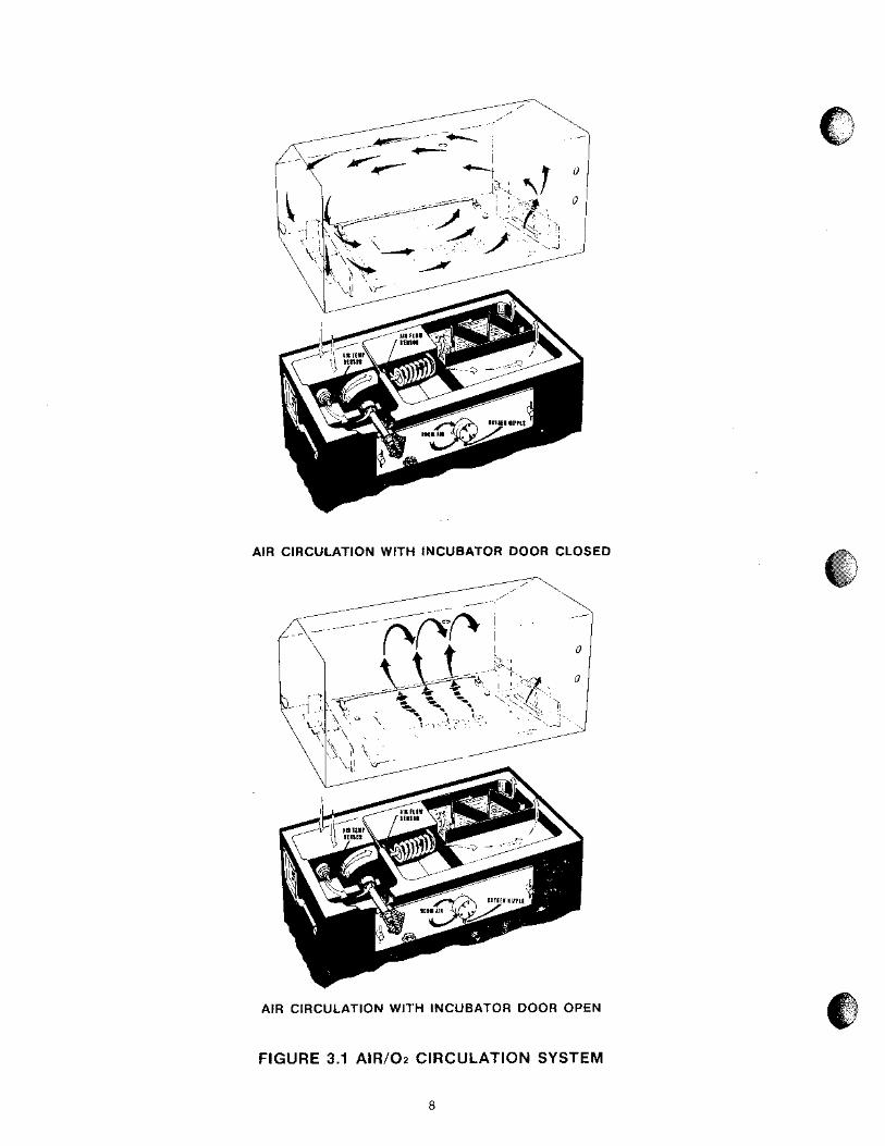
AIR ClRCULATlON WITH INCUBATOR DOOR CLOSED
AlR CIRCULATION WITH lNCUBATOR DOOR OPEN
FIGURE 3.1 AIR102 CIRCULATION SYSTEM

SKIN TEMPERATURE MODE (Modes C100). In thls mode of operation, the Infant's s k ~ n temperature can be malntalned at a temperature from 34.0 to 37 9" C as selected by the SKIN SET TEMP0 C thumbwheel sw~tch on the front panel A temperature senslng probe IS
attached d~rectly to the infant's skln, the ~nformat~on from the probe IS supplred to the heater control clrcultry whlch proportrons the heater output to malntaln the s k ~ n set temperature The alr temperature set temp does not control arr temperature while In the s k ~ n temperature mode, but actual alr temperature IS st111 dlsplayed The alr temperature probe (or a properly rnstalled a u x ~ l ~ a r y probe) st111 l ~ m ~ t s the alr temperature to 38 5" C If the Mode Selector Swrtch IS set to the Air Temperature mode whlle the skln probe remains connected, the S k ~ n Temperature drsplay will contrnue to dlsplay actual skrn temperature, but wlll not control If the probe IS d~sconnected from its receptacle at any time (Skrn mode of operatron), the Skln dlsplay blanks and an alarm IS activated The backup sensor w ~ t h ~ n the Arr Temperature probe remains In the clrcult to llmlt maxlmum dlsplayed air temperature to between 39 0 and 40 0" C
3.2.3 ALARMS
The lncubator is equipped with a system of alarms and temperature protection devices. Alarm indications are provided for power failure, inadequate air flow, probe fa~lure, h ~ g h temperature, and variation from set temp. Each time the unit is turned on, the unit is automatically stepped through an alarm check sequence to verify proper alarm function After the automatic alarm check is made, the low set temp alarm is disabled for about 60 minutes, or unti l the temperature reaches set temp. whichever occurs first; each of these alarms is described below.
AiR FLOW ALARM (Models el00 and 6200). A sensor located below deck in the normal air path of the fan con- trols this alarm. If air flow stops due to a fan failure, the temperature of the self-heated sensor rises causing the AIR FLOW alarm on the front panel to light and produces a pulsating audible tone. A short-circuited air flow sensor failure will also actuate the alarm within 9 to 18secondsof the occurrence of the failure. This alarm is non self- resetting and cannot becancelled by the Alarm SILENCE/ RESET Button until the alarm condition is corrected.
HIGH TEMPERATURE ALARM (Models ClOO and C200). A second sensor within the Alr Temperature Probe sounds thls alarm ~f the sensed temperature exceeds 39.5 + 0.5" C. A high temperature alarm is indicated by a flash~ng light and a continuous audible tone. Thisalarm is non self-resetting and cannot be cancelled by the Alarm SILENCE/RESET Button until the alarm condition is corrected
POWER FAILURE ALAWM (Models C40O and C200). If primary power to the lncubator IS rnterrupted for any reason, ~nc l ud~ng a d~sconnected power cord, an audlble alarm IS activated and an alarm lamp lights This alarm can be deactivated only by restor~ng the prlmary power or sett~ng the lncubator POWER Switch off
PROBE ALARM. Circuitry is provided to monitor the air, skin* and high temperature sensors for short-circuited, open-circuited, or disconnected conditions and the air flow sensor for open condition.
In the Model C100 Incubator, an indicator light flashesand an audible alarm sounds within 9 to 18secondsto indicate a defective air temperature, skin temperature or auxiliary sensor or an open-circuited air flow sensor (see IM- PORTANT). The probe alarm is also actuated if the skin temperature probe is disconnected while in the Skin Mode.
The Model C200 Incubator is equipped only for air control; therefore, no skin probe alarm is provided. The probe alarm is actuated to indicate a defective air temperature or auxiliary sensor or an open-circuited air flow sensor (see IMPORTANT).
IMPORTANT: The probe alarm will be actuated within 9 to 18 seconds if the airflow sensor is open-circuited and the temperature sensed below the mattress deck is greater than approximately 30°C; however, if the temperature sensed below the mattressdeck is less than approximately 30°C, the alarm will not be actuated. During warm-up, it can take anywhere from 15-30 minutes before the alarm actuates, depending on the temperature set point and ambient room temperature. The "probe alarm" indicating an open-circuited air flow sensor will not occur if the set point temperature is below 29°C.
In either Incubator, if a probe shorts (except for the air flow probe), it will appear as a high set temp violation, and the set temp alarm will light. Thisalarm is not self-resetting and cannot be cancelled by the Alarm SILENCEIRESET Button until the alarm condition is corrected. If a probe alarm occurs simultaneously with a set temp alarm, a shorted probe is probably the true cause of the alarm, since a shorted probe will appear as a high temperature condition.
SET TEMP ALARM. The Set Temp alarm is actuated if skin' or air temperature fluctuates from set temperature as follows: "Skin Temperature +I .O 1 0.3OC
-1 .O f 0.3" C Air Temperature + 1.5 rt_ 0.5' C
- 3.0 1 0.5" C A temperature below the set temp is indicated by a flashing light, a pulsating audible tone, and a low temperature reading; a temperature above the set temp is indicated by a flashing light, a continuous audible tone, and a high temperature reading. If a set temp alarm occurs simultaneously with a probe alarm, a shorted probe is probably the true cause of the alarm, since a shorted probe will appear as a high temperature condition.
The set temp alarm is self-resetting; that is, i f the alarm condition is corrected, the audible alarm is automatically silenced and the light is turned off.
The audlble set temp alarm can be silenced by depressing the SILENCE/RESET button; the activation of other audible and visual alarms will not beaffected by use of the 15 minute audible alarm silence. When silenced, the alarm lamp will remain on until the alarm condition is corrected. If the alarm condition is not corrected within 15 minutes. the audible alarm will be reactivated.
'Model ClOO only.

SECTION 4 OPERATION
4.1 OPERATING CONTROLS, BNDICATORS, AND CONNECTORS
Al l controls, indicators, and connectors required for operation of the Incubator are shown in Figure 4.1. An explanation of each item is provided in Table 4.1
FIGURE 4.1 OPERATING CONTROLS, INDICATORS, AND CONNECTORS (SHEET 1 OF 4)

TABLE 4.1 CONTROLS, INDICATORS, AND CONNECTORS
1 NAME I DESCRIPTION 1 INCUBATOR
Hood Lift Handle
Hood Hinge Latch
Mattress Elevator Levers
Iris Entry Port
Access Door ReleaseiLatch
Access Panel ReleaseiLatch
Hum~dity Fill Pipe
Tubing Access Port
Castor Lock
Oxygen Input Connection
Used to lift Hood assembly for cleaning or maintenance
Located on right rear corner of Incubator, latches Hood Assembly in open position; releases when depressed.
Used to position mattress in Fowler or Trendelenberg position.
Provides access to infant compartment
Releases/Latches Access Door
Rotated to latch or release Access Panel.
Provides means of filling humidity reservoir.
Provides routing for tubing, probe leads, etc. into infant compartment.
Located on diagonal corners of cabinet stand, restricts Incubator movement.
Located on rear of Incubator, provides connection point to Oxygen Limiter.

FIGURE 4.1 OPERATING CONTROLS, INDICATORS, AND CONNECTORS - MODEL @I00 (SHEET 2 OF 4)
FlGURE 4.1 OPERATING CONTROLS, INDICATORS, AND CONNECTORS - MODEL C200 (SHEET 3 OF 4)

POWER
TABLE 4.1 CONTROLS, INDICATORS, AND CONNECTORS (CONT.)
*CONTROL MODE
'SKIN SET TEMP " C
NAME
AIR SET TEMP " C
DESCRIPTION
INDICATORS
, HEATER
1 'AIR Temperature Mode
AIR TEMP " C
'SKIN Temperature Mode
'SKIN TEMP " C
ALARMS
I AIR FLOW
FRONT PANEL I
Turns lncubator on or off; illuminates when power is on. When first turned on, the lncubator is automatically stepped through a functional test sequence.
Selects SKIN or AIR temperature mode of control
Thumbwheel switch to adjust skin temperature set temp. Setting is adjustable from 34.0 to 37.g°C.
Thumbwheel switch to adjust air temperature set temp. Setting is adjustable from 20.0 to 39.g°C, but actual air temperature is limited to 38.5OC.
Silences the audible por t ion of set temp alarm for nominal ly 15 minutes; alarm silence is automatically overridden if another alarm occurs within the period of silence.
Also functions as alarm reset for air-flow, high temp and probe alarms, but only after alarm condition is corrected.
Provides indication of relative heater output
Indicates Air temperature control mode of operation
Digital display of lncubator temperature in air or skin' temperature control inode.
Indicates skin temperature control mode.
Digital display of skin temperature, whether in air or skin temperature mode of operation; display is blank if patient probe is disconnected.
Light flashes and a pulsating alarm sounds to indicate fan failure or a short-circuited air flow sensor. This alarm is not self-resetting and cannot be cancelled or reset until the alarm condition is corrected.
'Model C100 only

TABLE 4.1 CONTROLS, INDICATORS, AND CONNECTORS (CONT.)
'Model C100 only.
NAME
"Each time unit is turned on the low set temp alarm for the selected mode is delayed for about 1 hour or until the temperature stays within set temp for about 2-'h minutes.
DESCRIPTION
ALARMS (CONT.)
PROBE
SET TEMP
HIGH TEMP
POWER FAIL
FRONT PANEL (CONT.)
Light flashes and a pulsating alarm sounds to indicate a de- fective air temperature, skin* temperature orauxiliary sensor or an open-circuited air flow sensor (see IMPORTANT).
Also actuated if skin* temperature probe is disconnected while in Skin* Mode. This alarm is not self-resetting and can- not be cancelled or reset until the alarm condition is cor- rected.
IMPORTANT: The probe alarm will be actuated within 9 to 18 seconds if the air flow sensor is open and the tempera- ture sensed below the mattress deck is greater than approxi- mately 30' C.
'Skin Mode: Light flashes to indicate that skin tempera- '
ture is lo C above or below skin set temp. Continuous audible alarm indicates lo C above; pulsating audible alarm indicates l o C below.""
Air Mode: Light flashes to indicate that air tempera- ture is 1.5"C above or 3°C below set temp.
'
Continuous audible alarm indicates above; pulsating audible alarm indicates below."
The set temp alarm is self-resetting; that is, if the alarm con- dition is corrected, the audible alarm is automatically silenced and the light is turned off.
The audibleset tempalarm can be silenced by depressing the SILENCE/RESET button; the activation of other audible and visual alarms will not be affected by use of the 15 minute audi- ble alarm dlence. When silenced, the alarm lamp will remain on until the alarm condition is corrected. If the alarm condi- tion is not corrected within 15 minutes, the audible alarm will be reactivated.
Light flashes to indicate high Incubator temperature; a con- tinuous audible tone also sounds. This alarm is not self- resetting and cannot be cancelled by the Alarm SILENCE/ RESET Button until the alarm condition is corrected.
Lights steady to indicate that primary power to the Incubator has been interrupted; a steady audible alarm also sounds. This alarm can be deactivated only by restoring primary power or setting the lncubator POWER switch to off.

TABLE 4.1 CONTROLS, INDICATORS, AND CONNECTORS (CONT.)
'Model C100 only
NAME
FOR PROPER GROUND RELIABILITY USE A RECEPTACLE MARKEO HOSPITAL GRADE OR HOSPITAL USE
DESCRIPTION
FOR PROPER GROUND RELIABILITY USE A RECEPTACLE MARKEO HOSPITAL GRADE OR HOSPITAL USE
TO REMOVE CONTROLLER, ALL CONNECTIONS
IOOV, 1101120V MODELS 2201240V MODELS
SIDE PANEL
FIGURE 4.1 OPERATING CONTROLS, INDICATORS, AND CONNECTORS (SHEET 4 OF 4)
CONTROL
CIRCUIT BREAKER(S)
CONNECTORS
'PATIENT PROBE
AUXILIARY AIR PROBE
POWER CORD
Provide overload protection; depress to reset.
Accepts skin temperature probe for monitoring and con- trolling infant skin temperature. When connected. SKlN TEMP " C indicates temperature sensed by probe; when disconnected, SKlN TEMP " C is blank.
Accepts auxiliary air temperature probe and disconnects the internal air temperature probe to permit air temperature control by auxiliary probe.
Accepts AC power cord.

4.2 OPERATION E. ADJUST THE AIR SET TEMP°C THUMBWHEEL
The operating procedure is divided into two main sections: General Operation and Functional Checkout
SWITCH TO 34.0. All four HEATER lamps should light, indicating full heater output.
Procedure (4.2.1), and Operation During Use (4.2.2). The operational checkout should be performed each time the NOTE: Allow the unit to operate while continuing the
Incubator is put into service to verify proper operation of operational checkout.
all functions. The operation section should be used for subsequent routine operation. F. CHECK HOOD HINGE AND LATCH OPERATION for
proper positioning. Using the Hood Lift handle, slowly tilt the Hood back until theHood Latch engages. Close the Hood by releas~ng the Hood Latch as shown in F~gure 4.2
@ The lncubator should not be used i f i t fails to function as described. Service should be referred to qualified personnel.
@ The use of infant seats, head hoods or other accessories within the lncubator which can alter the air flow pattern may affect temperature uniformity, temperature variabil i ty, the correlat ion of the lncubator temperature reading to center mattress
4.2.1 GENERAL OPERATION AND FUNCTIONAL CHECKOUT PROCEDURE
The functional checkout should be performed before the lncubator is first placed into use and after any dis- assembly for cleaning or maintenance.
A. BEFORE CONNECTING THE lNClJBATOR to the power source, depress the POWER switch; the power failure alarm should sound, and the POWER FAIL indicator should light. This tests the operation of the power failure alarm circuit and ensures that the rechargeable battery that powers the circuit is in good condition. Depress the POWER switch a second time to silence the alarm.
B. CONNECT THE POWER CORD.
CAUTION: Make sure that the building power source is compatible with the electrical specifications shown on right side of the Incubator. For proper grounding reliability, connect the power cord only to a properly marked 3-wire hospital grade or hospital use receptacle. Do not use'extension cords.
C. ON THE MODEL 6100, set the CONTROL MODE switch to the AIR position.
D. DEPRESS THE POWER SWITCH. When on, the switch is illuminated. When initially turned on, the power unit performs a5-second self test, all alarm lamps light, the audible alarm is pulsed, and each temperature display (two in C100, one in C200) shows3eights (88.8). If any function does not occur, the unit requires service.
IMPORTANT: e This test should be performed on a daily basis. @ The self test tests the lamps displays, and audible
alarms, but does not completely simulate a func- tional failure.
FIGURE 4.2 HOOD RELEASE OPERATION
G. CHECK ACCESS PANEL DETENT. Rotate both latch/ releases inwardly and open the Access Panel as shown ~n F~gure 4 3, the Atr Curta~n Cover should rlse sl~ghtly as the Access Panel opens and the detents should create a noticeable "drag' during ~ n ~ t ~ a l movement of the panel Plvot the Access panel to the full open pos~tion (hang~ng stra~ght down)
FIGURE 4.3 ACCESS PANEL OPERATION
16
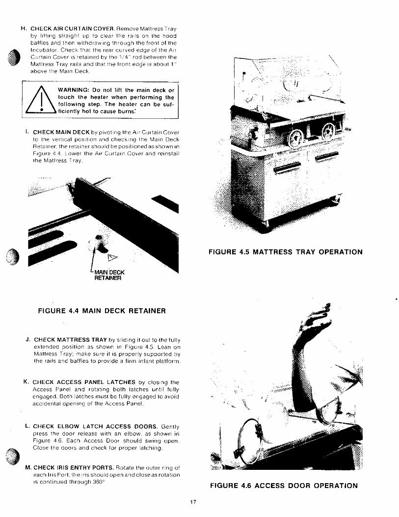
H. CHECK AIR CURTAIN COVER. Remove MattressTray by lifting straight up to clear the rails on the hood baffles and then withdrawing through the front of the Incubator Check that the rear curved edge of the Air Curtain Cover is retained by the 1 4 rod between the Mattress Tray r a ~ l s and that the front edge is about 1 above the Main Deck
WARNING: Do not lift the main deck or touch the heater when performing the following step. The heater can be suf- ficiently hot to cause burns.'
1. CHECK MAIN DECK by pivoting the Air Ccrrtain Cover to the vertical position and checking the Main Deck Retainer the retainer shoiild be positioned as shown ~n Figure 4 4 Lower the Air Curtain Cover and reinstall the Mattress Tray
FIGURE 4.5 MATTRESS TRAY OPERATION
FIGURE 4.4 MABN DECK RETAlNER
J. CHECK MATTRESS TRAY by sliding it out to the fully extended position as shown in Figure 4.5. Lean on Mattress Tray; make sure it is properly supported by the rails and baffles to provide a firm infant platform.
K. CHECK ACCESS PANEL LATCHES by c los~ng the Access Panel and rotsting both latches until fully engaged. Both latches must be fully engaged to avoid acc~derital opening of the Access Panel.
b. CHECK ELBOW LATCH ACCESS DOORS. Gently press the door release with an elbow, as shown in Figure 4.6. Each Access Door should swlng open. Close the doors and check for proper latching
M. CHECK IRIS ENTRY PORTS. Rotate the outer rlng of each Iris Port; the Iris should open and close as rotation is cont~nued through 360"
FIGURE 4.6 ACCESS DOOR OPERATION
17

CHECK MATTRESS ELEVATORS. Separately operate each Mattress Elevator by rotatlng handles downward as shown In F~gc~re 4 7
FIGURE 4.7 MATTRESS ELEVATOR OPERATlOM
N0TE:These elevator levers are provided to permit the infant to be positioned in Trendelenburg or Fowier position. Do not elevate both ends of the mattress at the same time except for possible use during magni- fication x-ray procedures. Never leave the infant un- attended while both elevators are raised.
NOTE: The Hood cannot be opened when either Mattress Elevator is raised.
buildup. The filter must be checked o n a basis and changed at least every three
, CHECK THE AIR INTAKE MICROFILTER. Loosen the two thumbscrews of the Air Intake Filter Cover and remove the cover as shown in Figure 4.8, Inspect the microfilter, if visibly dirty it should be replaced. Refer to paragraph 5.9 for additional instructions.
. CHECK AIRIOXYGEN SYSTEM by introducing a care- fully measured 8 LPM of oxygen, then monitoring levels within hood to verify that they reach the
Q. CHECK AIR TEMPERATURE MODE OF OPERATION. With all access openings closed, allow the lncubator to warm up to the thumbwheel setting (34.0°C); i t should take approximately one hour or less. While the unit is warming up, suspend the auxiliary probe through the hole in the top of the lncubator Hood and position the patient probe* in the center of the mattress surface; do not connect the probe plugs to the receptacles. When the AIR TEMP°C Display has stabilized, the number of HEATER lndicator lamps illuminated will typically be reduced to no more than two. Check that the digital display remains within 0.5OC of set temp for 15 minutes after stabilization.
R. CHECK AIR SET TEMP ALARM by setting the AIR SET TEMP°C thumbwheel first to 32.0°C, then to 38.0" C. An audible and visual alarm should activate at each setting after a 9 to 18 second delay, and cancel when the setting is returned to the display reading.
S. CHECK AUXlLlARY PROBE. Insert the Auxiliary Probe connector into the AUXILIARY AIR PROBE receptacle. Set the AIR SET TEMP0 C thumbwheel to 34.0°C. When AIR TEMP°C Display has stabilized, the number of HEATER lndicator Lamps illuminated will typically be reduced to no more than two. Check that the digital display remains within 0.5" C of set temp for 15 minutes after stabilization.
"8. CHECK SKlN TEMPERATURE MODE OF OPERA- TION. Connect the Patient Probe plug to the PATIENT PROBE Receptacle and set the SKlN SET TEMP°C thumbwheel to 36.0°C. Set the CONTROL MODE Swltch to the SKlN posltlon. When the SET TEMP alarm actuates, depress the Alarm SILENCE/RESET Button.
predicted level as indicated on the Filter Cover Assembly. FIGURE 4.8 FILTER COVER REMOVAL
*Model C100 only. 18

*U. CHECK SKlN SET TEMP ALARM. Allow lncubator Temperature t o s t a b ~ l ~ z e at 36 0°C Leave the CONTROL MODE Switch In the SKlN posltlon and set the SKIN SET TEMP°C thumbwheel to 37 5OC, then to 34 5°C An audlble and v~sual alarm should actlvate at each settlng and cancel when the settlng 1s returned to the dlsplay readlng
*V. CHECK SKlN PROBE ALARM. Leave the CONTROL MODE Switch in the SKlN position and discon- nect the Patient Probe from the receptacle. The audible and visual alarms should activate, the SKlN TEMP°C digital display should blank, and the HEATER Indicator Lamps should all go off. When the Skin Probe is reconnected, the lncubator should return to normal operation.
be sufficiently hot to cause burns; avoid
W. CHECK AIR FLOW ALARM. Set the POWER swltch to OFF Remove the Controller (Flgure 5 1) from the Incubator Remove the fan ~mpeller from the fan motor shaft, and reinstall the Controller In the lncubator Set the POWER sw~tch to ON and Walt for the end of the Auto-Test cycle (5 seconds) Wlthln 5 mlnutes, the AIR FLOW ~ndrcator should flash, a pulsating audlble alarm should sound, and all HEATER l~ghts should go out Reinstall the fan impeller and restore the
$ 4% "" $%
lncubator to normal operating cond~t lon before proceedng
X . CHECK MAXIMUM AIR TEMPERATURE. On the Model C100, position the probe end of the Patient Probe outside the lncubator (leave the CONTROL MODE Switch in the SKlN position) and set the SKlN SET TEMP°C thumbwheel switches to 39.9" C. On the Model C200, set the thumbwheel switches to 39.9"C. Allow the incubator to heat. If the SET TEMP alarm actuates, depress the Alarm SILENCVRESET Button.
The Incubator should not heat above 38.4"C +0.4OC, as indicated on the AIR TEMP°C display.
\I. CHECK HIGH TEMPERATURE ALARM. Position probe end of auxiliary probe outside the Incubator. If the SET TEMP alarm actuates, depress the Alarm SILENCE/RESET Button. When the HIGH TEMPERA- TURE Alarm actuates, disconnect the auxiliary probe and read the AIR TEMP°C display; the display should read 39.5 + 0.5" C.
Z. CHECK THE OXYGEN lNPUT VALVE FILTER. The Oxygen Input Valve Filter Cartr idge should be checked once every four months and replaced if the ends are gray or black. Refer to the Service Manual and qualified service personnel.
"el -3
AA. CHECKOUT IS COMPLETE. Disconnect and store the Auxiliary and Patient* Probes. If the lncubator is to be used, set the CONTROL MODE* Switch to the AIR position and leave the lncubator running until ready for use. If it is not going to be used it may be shut off.
4.2.2 OPERATION DURING USE
IMPORTANT: The lncubator should not be placed in service unless the General Operation and Functional Checkout Procedure (4.2.1) has been performed.
The lncubator should be ventilated and prewarmed in the air temp control mode to the temperature prescribed by the attending physician or according to Nursery Standing Orders. lncubator should be run with no water in humidity reservoir during prewarming.
NOTE: The air curtain that functions when the Access Panel is open is very delicate and can be disturbed by drafts, fans, air-condit ioning, etc. Take necessary measures to keep the lncubator away from these drafts.
'Model ClOO only.
WARNING:
@ For infant safety, d o not leave the infant unattended while the Access Panel is open.
@ The Mattress temperature may rise above the preset level i f the Access panel is left open. Therefore, do not leave i t open longer than essential. The air temperature indicator does not accurately reflect lncubator temperature when the Access Panel is open unless the Auxiliary Probe is being used.
@ When the Access Panel is opened, a curtain of warm air flows from beneath the front edge of the mattress toward the top of the Access Panel opening. The temperature of this air curtain is higher than the typical lncubator air tempera- ture, therefore the infant should be kept clear of this warm air path.
Raising the Hood i f leads or tubing are connected to the infant can result i n harm to the infant. There should be no need to raise the hood at any time while the infantis cared for in the Incubator. A11 necessary access to the infant can be achieved by means of the Access Panel, Access Doors, and Iris Entry Ports.
e Phototherapy units located too close to the lncubator may affect Rood wall temperature, lncubator air temperature and infant skin temperature.
J

A. PLACE INFANT IN INCUBATOR through opened Access Panel. Mattress Tray should be pulled out to stop as shown in Figure 4.5. Return Mattress Tray to normal use position and close Access Panel. Both Access Panel Latches must be positively secured to avoid accidential opening.
*Skin Temperature Control. Connect the plug of the Skin Temperature Porbe to the PATIENT PROBE Receptacle. Insert the probe into the hood compart- ment through the rrght Tubrng Access Port as shown In F~gure 4 9
B. ON THE MODEL C100, SELECT TEMPERATURE CONTROL MODE (AIR OR SKIN); the Model C200 operates w ~ t h Air Temperature Control only.
IMPORTANT: The temperature contro l mode and temperature settings should be prescribed by the attending physician. Infant 's rectal and/or axi l lary temperature should be routinely monitored according to the a t t end ing phys ic ian 's orders o r Nursery Standing Orders.
Air Temperature Control. Set the CONTROL MODE* Switch to the AIR position and set the AIR SET TEMP°C thumbwheel to the prescribed temperature Once stabilized, the lncubator temperature will be maintained wi th in 0 .5 "C of set temp. Note the following:
s The number of HEATER l~ghts illcrm~nated provides an indication of theamount of heater o i~ tp i l t required to maintain the Ir ici~bator alr temperature
@ The AIR TEMP C Display Indicates lncubator Temperature
* @ If a S k ~ n Probe IS connected to the PATIENT PROBE Receptacle the SKlN TEMP C D ~ s p a y w ~ l l Indicate temperature otherw~se this d~splay will be blank
Auxiliary Probe Air Temperature Control. If desired, the auxiliary probe can be used in the Air Temperature Control Mode of operation. When used, this probe automatical ly takes the place of the pr imary Air Temperature Probe which is located below the main deck. Otherwise, the uni t funct ions as described under Air Temperature Control.
Insert the probe end through the hole on the topof the Hood. Make sure the probe hangs freely inside the Incubator. To use the probe, insert its plug into the AUXILIARY AIR PROBE receptacle.
WARNING: FOP proper temperature control, the Auxiliary Probe must be directly beneath the hole in the Hood. Do not operate the lncubator with the Auxiliary Probe outside the lncubator or
other than as recommended. Overheating will occur.
FIGURE 4.9 TUBING ACCESS PORT
The skin area where the probe is to be placed should be thoroughly cleaned and dried before the probe is placed on the skin. When the infant is on its back or side, the Probe should be placed on the abdomen. halfway between the xyphoid and the umbi l icus. When the infant is prone, the probe should be on the infant's back. The probe must never be placed under the infant or used rectally.
Attach the probe to the infant using an Air-Shields SofSpots'" Probe Cover, as shown in Figure 4.10. To stabilize the attached probe, place a piece of tape over the probe wire approximately three to four cent~meters from the probe tip.
Set the CONTROL MODE Switch to theSKIN position and set the SKlN SET TEMP°C thumbwheel to the desired temperature. Once stabilized, the infant's skin' temperature will be automatically controlled within 0.3" C of the set tern^.
Note the fol lowing:
@ The number of HEATER lights illuminated prov~des an indicat ion of the amount of heater output required to maintain Skin Temperature.
a The SKlN TEMP°C Display indicates actual infant skin temperature.
@ The AIR TEMP" C Display indicates actual incubator air temperature necessary to maintain s k ~ n temper- ature The AIR Temperature settlng will have no control of alr temperature
'Model ClOO only

Remove backing from SofSpotsTM Probe Cover
C. OXYGEN. Oxygen can be administered from a wall source or the oxygen cylinder (accessory) on the Incubator Cabinet Stand.
WARNING:
@ Improper use of supplemental oxygen can cause serious side effects including blindness, brain damage and death. The risks vary with each infant. The method, the concentration and the duration of oxygen administration should be prescribed by the attending physician.
@ If i t is necessary to administer oxygen in an emergency, the attending physician should be notified immediately.
@ The use of the VapojetteR Humidifier or other means of external humidi f icat ion wi l l alter predicted incubator oxygen concentrations. Refer to Cat. No. 26 991 30 for operating instructions for the VapojetteR Humidifier.
@ The oxygen concentration inspired by an infant does not predictably determine the part ia l pressure of oxygen (pO2) in the blood. When deemed advisable by the attending physician, blood pOz should be measured by accepted clinical techniques.
NOTE: See current edition of "Guidelines for Perinatal Care" of the American Academy of Bediatrics/The American College of Obstetricians and Gynecologists.
Connect the output of the oxygen flowmeter to the nipple of the Oxygen Input Valve (Figure 4.1 I ) , using 3/16-inch ID surgical tubing. An oxygen concentration gu~de is provided in Figure 4.12. This guide also appears on the Air Input Filter Cover on the back of the Incubator.
Attach Probe
FIGURE 4-10 ATTACHING SKIN PROBE OXYGEN CONCENTRATION GUIDE
SOH2 - 60H2 OPERATION
O X Y G E N I N P U T N O R M A L R A N G E Oz0/0
I L L < $ < h l l N L l T E C F O h F I N A L , O N r , E Y T 9 L ; T I O t I I S A F T E R EACH CHANGE OF 0 . 1 7 C 1 E b ~ '~01'4 ' E l I I N b NOTE THE ABOVE VALUES ARE INTENDED AS GUIDELINES ONLY READJUST FLOW AS REQUIRE0 TO ACHIEVE PRESCRIBED CONCENTRATION SEE WARNING LABEL AND IMPORTANT OPERATING INSTRUCTIONS -*
FIGURE 4.11 OXYGEN INPUT VALVE FIGURE 4.12 OXYGEN CONCENTRATION GUIDE
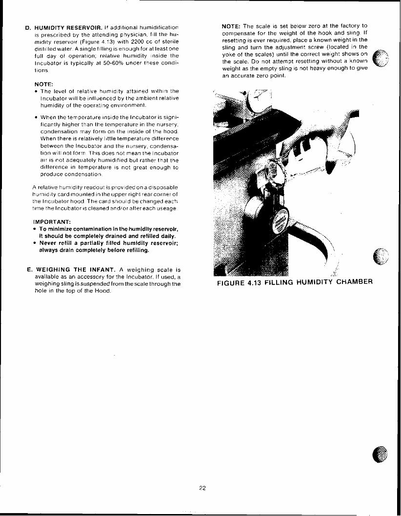
D. HUMIDITY RESERVOIR. I f add~t ional humidification is prescribed by the attending physician, f ~ l l the hu- midity reservoir (F~gure 4.13) with 2200 cc of sterile distilled water. A single filling is enough for at least one full day of operation; relative humidity inside the lncubator is typically at 50-60% under these condi- tions.
NOTE: The level of relative humidity attained within the Incubator will be influenced by the ambient relative humidity of the operating env~ronment.
@ When the temperature lnslde the lncubator is signi- ficantly hlgher than the temperature in the nursery, condensation may form on the inside of the hood. When there is relatively little temperature difference between the lncubator and the nursery, condensa- tion will not form. Thls does not mean the lncubator air is not adequately humidified but rather that the difference In temperature is not great enough to ~ r o d u c e condensation.
A relative humldity readout is p rov~ded on a disposable hurn~dl ty card mounted ~n the upper r ~ g h t rear corner of the Incubator hood. The card should be changed each tlme the Incubator ~scleaned and/or after each useage
IMPORTANT: To minimize contamination in the humidity reservoir, it should be completely drained and refilled daily.
@ Never refill a partially filled humidity reservoir; always drain completely before refilling.
E. WEIGHING THE INFANT. A we igh ing sca le i s available as an accessory for the Incubator. If used, a weighing sling issuspendedfrorn thescalethrough the hole in the top of the Hood.
NOTE: The scale IS set below zero at the factory to compensate for the we~ght of the hook and sllng If resettlng IS ever required, place a known welght In the sllng and turn the adjustment screw (located In the yoke of the scales) u n t ~ l the correct we~gh t shows on the scale Do not attempt resettlng wlthout a known weight as the empty s l ~ n g IS not heavy enough to give an accurate zero polnt
FIGURE 4.13 FILLING HUMIDITY CHAMBER

SECTION 5 CLEANING AND MAINTENANCE
5.1 GENERAL
This sect1011 p r o v ~ d e s cleaning and marntenance instruc- t ~ o r i s Where riecessary disassembly rnst r i ic t~ons are probided Maintenance other than that p r o v ~ d e d i n t h ~ s scctiori s h o ~ ~ l d be performed on ly by qua l~ f red servlce ~ e r s o r i r i e l
5.2. CLEANING
When an infant 1s d~scharged or at least once a week, the I r ic~ ibator shoi i ld be thoroughly c leaned and drsinfected C lean ing can mos t effect ively b e accornpl rshed b y d~sasser-iiblirig then grouplng the parts and o r assem- blies In ca tegor~es accord ing to the method of c leaning
5.2.1 DISASSEMBLY FOR CLEANlNG
NOTE: For routine cleaning there is no need to separate the HoodIBase assembly from the Cabinet Stand. If separation is necessary refer to the Installa- tion Section.
sufficiently hot to cause burns; avoid removing the Controller or touching the heater until the unit has been switched off for at least 45 minutes.
A. REMOVE THE CONTWQLLER. Disconnect the Power Cord and Probes from the side of the Incubator. Release the latch on each side of the Controller as shown in Figure 5.1, then withdraw the unit from the Incubator.
FlGURE 5.1 REMOVAL OF CONTROLLER

* B . REMOVE THE HOOD INNER WALL. Remove the Inner Wal l as descr~bed in F l g ~ ~ r e 5 2
1 RELEASE FRONT OF INNER WALL by pushing slightly back in direction of hood slope, then down.
2 RELEASE REAR OF INNER WALL w h ~ l e rest~ng front edge of inner wall on your arm, l ~ f t rear of Inner wall, pull toward you to release, then lower
3 LOWER REAR OF INNER WALL AS FAR AS 4 REMOVE INNER WALL IT WILL GO. by lowering in direction shown
*Model C100 only.
FIGURE 5.2 REMOVAL OF INNER WALL

* C . REMOVE ACCESS PANEL INNER WALL (HEAT SHIELD). Refer to Figure 5.3. With the Access Panel completely open, remove the Inner Wall by simultan- eously pulling o ~ i t at the top and pushing ~n the down- ward direction
FIGURE 5.3 ACCESS PANEL INNER WALL REMOVAL
4: ,"
"PD. REMOVE MATTRESS TRAY A N D AIR CURTAIN COVER. Close the Access Panel and latch the Hood Assembly in the open position, then lift out the Mattress Tray Remove and discard the disposable mattress cover.
Lift the front of the Air Curtain Cover, swing it toward the back of the Incubator pastthevertical position until you feel it snap free, then slide it s l~ght ly forward to remove.
E. REMOVE M A I N DECK. Rotate the Main Deck Retainer (Figure 5.4) parallel with the slot, then lift out the Main Deck and Hood Seat Gasket.
FBGURE 5.4 WEMQVAL OF MAIN DECK *Model C100 only.
F. REMOVE AIR INTAKE TUBE. Grasp the Air Intake Tube (F ig~ i re 5.5), twist and pull it toward the front of the Incubator until the end of the tube clears the gasket. Remove the tube from the base assembly.
FIGURE 5.5 REMOVAL OF AIR INTAKE TUBE
G. REMOVE DISPOSABLE ACCESS D O O R C U F F from each Access Door Gasket by pulling it off from the outside; discard the cuffs.
W. REMOVE ACCESS D O O R GASKET from each Access Door hole by pulling it off from the outs~de.
I. REMOVE T U B I N G ACCESS PORTS from each side of the Hood by pulling them free.
J. REMOVE DISPOSABLE IRIS ENTRY P O R T SLEEVES by pulling each Sleeve off the retainer rings. discard the sleeves.
K. REMOVE T H E AIR-INTAKE MICROFILTER COVER by loosening the two thumbscrews.
5.2.2 CLEANING
CLEANING AGENTS. An iodophor or quaternary disinfectant-detergent registered by the U.S. Environ- mental Protection Agency should be used, but only after the lncubator is empty and disassembled as described in paragraph 5.2.1. A cleanser such as Air-Shields Kleen- aseptic@ Germicidal Surface Cleanser may be used. When using any cleaning agent follow the manufacturer's direc- tions for use. After removing all solid wastes and contamin- ants from the disassembled parts, clean them as follows:

' SKIN PROBE. Use a d is~nfectant -detergent to thoroughly clean all surfaces, then d ry w ~ t h a clean c lo th or paper towel.
HUMIDITY CHAMBER AND FlLL PIPE. AIR INTAKE TUBE. ACCESS DOOR GASKETS. TUBING ACCESS PORTS. AND MAlN DECK GASKET. Fil l tt ic h~i r l i ic i i ly cli;irl~I,t>r wit t i ;i ciisirifc'c:t,~nt-detergerit the11 rrniovt ' the W - s l ~ a p c i l B;iffli> fro111 I h c C ~ ~ ; I I ~ I ~ C I and dry r t wttt i a clean clot!i 0 1 p ~ i p c r towel Place Itie AI I lr i lake Tube Access D o o ~ Gaskt?ts Ttit>ir-ig Acctiss F'otts arid Ma in Deck Gnskct into t t i i , s o l ~ i t i o n
NOTE: I f r iecessaly n larger container niay be i ised. t ~ i i t i f ttie ct~arl iber I S not irsed then the Fil l Pipe and HLIIIIICII~Y C/iciri iber rlitrst be cleaned separately
Al low thcnl to soak as ~ e c o n i m e n d e d by the clearling s o l ~ i t i o n s rl iantifacttrrer, then remove then1 and dry coriipletely wit t i a clean c lo th or paper towel D r a ~ n the H~rri-i idity Cti,irlit~er scrub i t thoroi igt i ly ~ n c l t i d t n g all l rid en tali or is ttieri dry the chamber and Fil l Pipe ( i n s ~ d e arid o i i t ) with a cleat1 c lo th or paper towel
I f i iecessaly to rrrl-iove the f i l l p ipe for clearirng rotate the Fil l Pipe A s s e ~ l i t ~ l y about 1 4 turn to ttie left Looser? the t t i ~ r m t ~ s c ~ e w that secLires the FIII Pipe Bracket arid rotate the bracket 1 4 turn to the left Uriscrew t i le Fi l l P ~ p e Asser~ib ly b y rolatrny co i rn te r~ lockwrse as shown rn Figtire 5 6 Clean Fil l Pipe Assernbly and the sleeve that t ~ e c o m r s a loose part when the Fil l Pipe Assernbly is t r~ iscrewed
FIGURE 5.6 REMOVAL OF HUMIDITY FlLL PIPE ASSEMBLY
'Model C100 only
CONTROLLER. The portions of the Controller external to the controlled Incubator environment include the front panel and the top, bottom, and two sides of the chassis. These port ions may be wiped clean wi th a c lo th dampened with a disinfectant-detergent.
CAUTION: Some chemical cleaning agents may be conductive and/or leave a residue which may permit a build-up of dust or dirt which may be conductive. Do not permit cleaning agents to contact electrical components. Do not spray cleaning solutions onto any of these surfaces.
The portions of the Controller that are within the Incubator's controlled environment are on the rear surface; included are the air temperature probe, the fan impeller, the heater, the gaskets, and the surface of the Controller to which these components are mounted.
CAUTION: Failure to clean could result in sufficient l int bui ldup to reduce airf low, which wi l l affect temperature control and cause high oxygen concen- trations.
1. Remove any lint buildup; pay particular attention to the fan impeller, heater, air temperature probe, and air flow sensor.
2 Clean these surfaces with a disinfectant-detergent then dry with a clean cloth or paper towel.
NOTE: A disinfecting tank is available as an accessory from Air-Shields to facilitate cleaning the rear surface of the Controller. The Controller rear surface is im- mersed into the tank after filling it with a disinfectant- detergent, then allowed to soak as recommended by the manufacturer of the cleaning solution.
MATTRESS TRAY, AIR CURTAIN COVER, MAlN DECK. Use a disinfectant-detergent to clean all surfaces thoroughly, then dry with a clean cldth or a paper towel.
HOOD AND CABlNET STAND. Use a disinfectant- detergent to clean all surfaces of the hood thoroughly, including the inner wall' and access door heat shield'. Make sure to clean all holes, indentations, baffles, etc., then dry with a clean cloth or paper towel.
CAUTION:
@ Alcohol can cause crazing of the clear Plexiglas" Hood. Do not use alcohol for clean~ng.
Do not expose the hood assembly to d~rect radiation from germ~c~dal lamps. Ultrav~olet radiat~on from "
these sources can cause cracklng of gaskets, fading of paint, and crazing of the clear Plexiglas@ Hood.

AIR-INTAKE MICROFILTER. Do not attempt to clean or reverse the microf~lter If v~sibly d ~ r t y , or older than 3 months ~t should be replaced Before instal l~ng a new f~ l te r , clean the M~crof i l ter chamber and cover w ~ t h a disinfectant-detergent.
concentration and/or cause carbon dioxide buildup. Be sure the filter is checked on a routine basis commensurate with local conditions.
5.2.3 REASSEMBLY AFTER CLEANING
After cleaning all parts and assernbl~es as descr~bed in paragraph 5.2.2, reassemble as described below.
A. INSTALL THE AIR INTAKE TUBE (Into the Base Assembly) by reversing the procedure shown in Figure 5 5.
B. INSERT HUMIDITY CHAMBER BAFFLE ~ n t o the Hum~dt ty Chamber.
WRONG MAlN DECK POSITION-Main
deck placed up on gasket on one side, permitting air flow
as shown by dashed line.
CORRECT MAIN DECK POSITION-Main
deck placed down on conditioning chamber top..
C. INSTALL THE MAlN DECK AND H O O D SEAT GASKET into the Base Assembly as shown In F~gure 5.7. Rotate the M a ~ n Deck Reta~ner (Figure 5.4) to secure the deck.
D. INSTALL THE AIR CURTAIN COVER AND MAT- TRESS TRAY.
WARNING: The Air Curtain Cover must be properly installed ior correct temperature control.
Hook the 11p on the bottom rear of the Air Cu r ta~n onto the rod at the rear of the M a ~ n Deck Assembly, then lower the cover toward the front of the Incubator to the rest p o s ~ t ~ o n . Close the Hood Assembly and check for proper operat~on of ttie Air Cu r ta~n Cover. The Air Cu r ta~n Cover IS operating correctly ~f it rises slightly when the Access Panel is opened Install the Mattress Tray by pos~ t~on ing ~t a few inches above the mattress ra~ ls . then lowertng straight down.
E. INSTALL DISPOSABLE MATTRESS COVER. Place a new disposable Mattress cover over the mattress, then place the mattress onto the tray.
FIGURE 5.9 INSTALLATION OF MAIN BECK AND HOOD SEAT GASKET
27

F. INSTALL DISPOSABLE IRIS ENTRY PORTSLEEVES. Install a new Iris Entry Port Sleeve as shown in F~girre 5 8
NOTE: I f the lnc~rbator I S to be gas sterilized wait ~ ~ r i t l l after sterlllzatlon to ~nsta l l new sleeves
1 Install the smaller diameter elastic band 2 Fold back and slip larger elastic band of a new sleeve over the inner ring of the port housing.
over the outer ring of the port housing.
3 Rotate outer r ing t o close. I f p roper ly instal led, the sleeve wi l l open again if rotation is reversed.
FIGURE 5.8 INSTALLATBON OF IRIS ENTRY PORT SLEEVE

G. INSTALL A TUBING ACCESS PORT Into the front edge of each s~de of the Hood. Replace if distorted or torn
H. INSTALL AN ACCESS DOOR GASKET beh~nd each
L. INSTALL A NEW AIR INTAKE MICROFILTER, i f necessary. Replace the Air Intake Microfilter Cover and tighten the two thumbscrews. If a new filter is installed, indicate the date on the place provided on the cover.
Access Door. as shown rn Figure 5.9. IMPORTANT: A complete functional checkout (paragraph 4.2.1) should be performed before returning the unit to service.
ACCESS BOOR CUFF GROOVE
ACCESS DOOR GASKET
PLEXIGLAS HOOD
INSIDE OF INCUBATOR
FIGURE 5.9 INSTALLATION OF ACCESS BOOR GASKET
I. INSTALL A NEW ACCESS DOOR CUFF onto each Access Door Gasket by stretching the larger diameter elastic band into the groove in the gasket. When installed correctly, the cuff has a small opening at its center. The Access Door should latch with slight pressure, and should open when the latch button is depressed.
NOTE: I f the lncubator is to be gas sterilized, wait untrl after sterilizat~on to install new sleeves.
"J. INSTALL HOOD INNER WALL by reversing the procedure shown in Figure 5.2.
K. INSTALL THE HEAT SHIELD onto the Access Panel
*Model ClOO only.
5.3 GAS STERILIZATION
Prior to gas sterilization, the entire lncubator should be thoroughly cleaned as described elsewhere in this section. All used disposable elements such as iris sleeves, access door cuffs, mattress covers, etc., should be removed and discarded as described in the cleaning instructions. New disposable elements should be installed after sterilization.
Release the Controller latchesand slide the unit out about 1/4". The Access Panel may be closed, but the Access Doors should be left open. The Air Intake Microfilter may be left in place.
CAUTION: Sterilization temperature should not exceed 130" F (54.5" C).
NOTE: Gas sterilization does not eliminate the need for routine replacement of the Air Intake Microfilter.
Standard Gas sterilization procedures as programmed by automatic equipment such as made by American Steri- lizer and Wilmot Castle are satisfactory as these do not normally exceed 130" F (54.5" C).
Upon completion of gas sterilization, an aeration period of 16 to 24 hours should be allowed. The Controller should be properly secured in place and the lncubator should be operated in a dry condition for theentire period of aeration at a temperature of 32 to 35" C. After aeration, if the unit is not to be used immediately,adisposabledu~t cover should be placed on the Incubator.
IMPORTANT: A complete functional checkout proce- dure (paragraph 4.2.1) should be performed before returning the unit to service.
5.4 TROUBLESHOOTING
Troubleshooting for the operator of the lncubator is presented in Table 5.1. If the fault cannot be localized from the chart, the unit should be removed from use and servicing should be referred to factory trained or otherwise qualified personnel.