Isolation Valve Selection
29
RP 62-2 ISOLATION VALVE SELECTION PHILOSOPHY FOR OIL AND GAS PRODUCTION AND PROCESSING September 1996 Copyright © The British Petroleum Company p.l.c.
-
Upload
kalyanvarman -
Category
Documents
-
view
167 -
download
15
description
Isolation Valve Selection
Transcript of Isolation Valve Selection

RP 62-2
ISOLATION VALVE SELECTIONPHILOSOPHY FOR OIL AND GASPRODUCTION AND PROCESSING
September 1996
Copyright © The British Petroleum Company p.l.c.
rezaei
tadvin-arm

Copyright © The British Petroleum Company p.l.c.All rights reserved. The information contained in this document is subjectto the terms and conditions of the agreement or contract under which thedocument was supplied to the recipient's organisation. None of theinformation contained in this document shall be disclosed outside therecipient's own organisation without the prior written permission ofManager, Standards, BP International Limited, unless the terms of suchagreement or contract expressly allow.

BP GROUP RECOMMENDED PRACTICES AND SPECIFICATIONS FOR ENGINEERING
Issue Date September 1996
Doc. No. RP 62-2 Latest Draft No.
Document Title
ISOLATION VALVE SELECTIONPHILOSOPHY FOR OIL AND GASPRODUCTION AND PROCESSING
APPLICABILITY BPXRegional Applicability: International
SCOPE AND PURPOSE
This Recommended Practice gives technical guidance for the selection of valves for landbased and offshore oil and gas processing facilities.
The main purpose of this document is to provide guidance to all new projects andoperating assets to help them minimize whole life cost whilst maintaining a consistentapproach to valve selection which acknowledges company experience.
AMENDMENTSAmd Date Page(s) Description___________________________________________________________________
CUSTODIAN (See Quarterly Status List for Contact)
ValvesIssued by:-
Engineering Practices Group, BP International Limited, Research & Engineering CentreChertsey Road, Sunbury-on-Thames, Middlesex, TW16 7LN, UNITED KINGDOM
Tel: +44 1932 76 4067 Fax: +44 1932 76 4077 Telex: 296041

RP 62-2ISOLATION VALVE SELECTION PHILOSOPHYFOR OIL & GAS PRODUCTION & PROCESSING
PAGE i
CONTENTS
Section Page
FOREWORD ............................................................................................................... iii
1. INTRODUCTION................................................................................................... 1
2. APPLICATION....................................................................................................... 1
3. UNITS...................................................................................................................... 2
4. ASSUMPTIONS...................................................................................................... 2
5. MATERIALS .......................................................................................................... 2
6. CONSTRUCTION/ COMMISSIONING CONDITIONS..................................... 2
7. ASSUMED CONDITIONS FOR OIL/ GAS PROCESSING................................ 2
8. RECOMMENDED VALVE SELECTIONS.......................................................... 3
9. MAINTENANCE CONSIDERATIONS ................................................................ 3
10. ISOLATION REQUIREMENTS ........................................................................... 4
11. NOTES ON SPECIFIC VALVE TYPES AND APPLICATIONS .................. 5
11.1 Main ESD Valves ............................................................................................. 511.2 Pig launcher/Receiver Isolation ......................................................................... 511.3 Butterfly Valves................................................................................................ 611.4 Plug Valves ...................................................................................................... 711.5 Check Valves.................................................................................................... 8
12. RELATED ISSUES................................................................................................. 9
12.1 Weight/Cost Minimisation................................................................................. 912.2 Vent/Drain etc. Plugs...................................................................................... 1012.3 Seal selection.................................................................................................. 1012.4 Fugitive Emissions .......................................................................................... 1112.5 Safety/ Relief Valves....................................................................................... 1312.6 Subsea Application ......................................................................................... 13
TABLE 1. ASSUMED CONDITIONS FOR OIL AND GAS PROCESSING......... 15
TABLE 2. ISOLATING/BLOCK VALVE RECOMMENDATIONS..................... 17
RP 62-2ISOLATION VALVE SELECTION PHILOSOPHYFOR OIL & GAS PRODUCTION & PROCESSING
PAGE ii
TABLE 3. CHECK VALVE RECOMMENDATIONS............................................ 21
APPENDIX A.............................................................................................................. 22
DEFINITIONS AND ABBREVIATIONS .............................................................. 22
APPENDIX B.............................................................................................................. 23
LIST OF REFERENCED DOCUMENTS............................................................... 23

RP 62-2ISOLATION VALVE SELECTION PHILOSOPHYFOR OIL & GAS PRODUCTION & PROCESSING
PAGE iii
FOREWORD
Introduction to BP Group Recommended Practice and Specifications for Engineering
The Introductory volume contains a series of documents that provide an introduction to theBP Group Recommended Practices and Specifications for Engineering (RPSEs). In particular,the 'General Foreword' sets out the philosophy of the RPSEs. Other documents in theIntroductory volume provide general guidance on using the RPSEs and backgroundinformation to Engineering Standards in BP. There are also recommendations for specificdefinitions and requirements.
Value of this Recommended Practice
This Recommended Practice provides flexible valve type recommendations for the principalareas of oil and gas processing facilities adherence to which should ensure that whole life costis minimised. The Recommended Practice also provides a benchmark against whichalternative proposals can be assessed.
Application
Text in italics is Commentary. Commentary provides background information which supportsthe requirements of the Recommended Practice, and may discuss alternative options. It alsogives guidance on the implementation of any "Specification" or "Approval" actions; specificactions are indicated by an asterisk (*) preceding a paragraph number.
Feedback and Further Information
Users are invited to feed back any comments and to detail experiences in the application ofBP RPSE's, to assist in the process of their continuous improvement.
For feedback and further information, please contact Engineering Practices Group, BPEngineering or the Custodian. See Quarterly Status List for contacts.

RP 62-2ISOLATION VALVE SELECTION PHILOSOPHYFOR OIL & GAS PRODUCTION & PROCESSING
PAGE 1
1. INTRODUCTION
Valve selection has a major effect on the whole life cost of an asset. The need toreplace malfunctioning equipment can soon wipe out CAPEX savings made byinappropriate selection.
In the past, BP Exploration has lacked a means of ensuring that valve selections beingmade by engineers working on new developments or asset refurbishment projectsfollowed a consistent pattern which accorded with the knowledge gained by thecompany from operating and test experience. This document is intended to addressthat deficiency.
The philosophy is commercially sustainable (i.e. there are sufficient qualified suppliersof each recommended valve type to ensure competitive tendering or alternativesourcing - not always the case in the past) and, where possible, alternatives areproposed which may offer CAPEX or weight savings without unduly compromisingoperating life. In some cases more expensive alternatives are listed which may befound useful in especially onerous conditions.
In addition to providing general valve selection recommendations in Section 8,particular applications and valve types (e.g. riser emergency shut down valves,equipment isolation etc.) are addressed separately in Section 11. Important relatedissues are dealt with in Section 12.
It is recognised that there will be unique conditions relating to certain projects whichhave to be addressed; the aim of this Recommended Practice is to provide a benchmarkwith which alternative proposals can be compared and against which they should bejustified.
This document is complimentary to BP Group RP 62-1 "Guide to Valve Selection" which containssufficient information for appropriate valve selections to be made but covers a much wider field thanoil and gas production. The high textual content of this document may, perhaps, have discouragedbusy project engineers from using it (but it should be noted that the computerised version (hypertext)can produce valve selections very quickly).
BP Group RP 30-3 should be consulted by all those concerned with selecting or specifying actuatedshut-down valves and this document also provides recommendations covering control valves
2. APPLICATION
This Recommended Practice is intended to be used by all new BP Explorationdevelopment projects (and significant asset modification/refurbishment projects) as thebasis for a project specific valve selection philosophy. It has been written with a viewto minimising whole life costs (on which valves can have a major impact) and accordswith BP operating and test experience.

RP 62-2ISOLATION VALVE SELECTION PHILOSOPHYFOR OIL & GAS PRODUCTION & PROCESSING
PAGE 2
3. UNITS
Units are SI metric except for nominal pipe size (NPS) which is stated with the DNequivalent. Pressure units stated in bar refer to gauge pressures.
4. ASSUMPTIONS
The assumptions made regarding operating conditions are clearly stated and cover themost general case. Trim materials and, in some cases, valve types will have to bealtered where particular conditions require this.
5. MATERIALS
This BP Group Recommended Practice is primarily concerned with functionality andmakes the assumption that valve pressure boundary materials will be selected to becompatible with the connected pipe, the working fluid and the operating conditions.Except as included in Section 12.1, specific material recommendations are not made.
BP Group RP 62-1 includes information on most commonly encountered valve materials.
6. CONSTRUCTION/ COMMISSIONING CONDITIONS
Conditions during construction, line flushing and plant start-up are frequently the mostsevere that a valve will see. Even where the normal operating conditions are clean,soft seated valves can suffer permanent damage unless appropriate steps are taken toprotect them.
Selection of valves suitable for dirty service is the best course. Where this is notpossible consideration should be given to installing critical valves after flushing iscompleted, although relative costs will have to be carefully evaluated. In the case ofsoft seated ball valves of moderate to large size, protection by means of sealantapplication has been shown to be effective and may offer the most economicalternative.
BP Sunbury Branch report 124 240 deals with this topic and is available from the custodian of thisRecommended Practice.
7. ASSUMED CONDITIONS FOR OIL/ GAS PROCESSING
For each zone of the system representing common operating conditions the assumedfluid condition (clean, dirty, wet etc.), along with the assumed typical maximumpressure and temperature are listed in Table 1. Where conditions are known to differfrom the assumed case, appropriate adjustments should be made. In most cases theassumption is conservative, but not always (eg. fuel gas 'dry'). The recommendationsare largely unaffected by the form of the produced fluid (oil, gas, multiphase) although

RP 62-2ISOLATION VALVE SELECTION PHILOSOPHYFOR OIL & GAS PRODUCTION & PROCESSING
PAGE 3
this will have to be taken into account (isolation and low temperature potential of gas,corrosivity of produced water etc.) when making a final selection.
8. RECOMMENDED VALVE SELECTIONS
Table 2 provides a list of recommended isolation/block valve selections against eachzone of the system representing common operating conditions.
Table 3 provides similar recommendations for check valves.
Possible alternatives (which, in some cases, may offer CAPEX savings) are listed.
Most of the alternatives listed offer equivalent (or better) performance than the primerecommendation. It should be recognised, however, that some risk of reduced operating life(compared to the main recommendations) may be attached to a minority of these. Efforts to establishthe suitability of these valve types from several suppliers are ongoing (via the NEL Valve User TestConsortium or, in some cases, field trials) but, until suitability is proven, caution is necessary. Incase of doubt consult the custodian of this RP.
It is not intended that these tables be issued to subcontractors, vendors etc. unless accompanied byguidance from the project/ design contractor as to which alternatives are acceptable in the particularcircumstances. If this advice is ignored, the cheapest alternative is likely to be selected regardless ofany other considerations.
BP Group RP 62-1 provides detailed information on the merits/limitations of the different valvetypes.
9. MAINTENANCE CONSIDERATIONS
The maintenance strategy being adopted for valves on the facility can affect both theultimate choice of valve type and the spares requirements so it is important to establishthis early in the selection process.
If it is intended that work will be carried out in situ, welded pipe connections becomepossible but valve internals will need to capable of being accessed and removed via thebonnet etc. This facility is automatically provided in the case of gate valves, globevalves, swing check valves, plug valves and top entry ball valves. However, the easewith which internals can be withdrawn should be carefully investigated and it may benecessary to provide lifting/handling facilities in the case of large valves. It should benoted that in situ maintenance cannot be conducted on butterfly or wafer check valves.
Where the intention is to remove all valves to a workshop for maintenance maximumflexibility of valve selection is possible. Spares holding may be increased, however,because of the necessity to provide complete replacement valves.

RP 62-2ISOLATION VALVE SELECTION PHILOSOPHYFOR OIL & GAS PRODUCTION & PROCESSING
PAGE 4
10. ISOLATION REQUIREMENTS
Where double block and bleed isolation is required by the isolation philosophy this canbe achieved in three ways:
(1) Two single seated valves in series with a bleed from the connecting pipe.(Acceptable for all applications.)
(2) A single valve having two independent seats sealing in the same direction and aconnection into the cavity between the seats. (Cost savings may be realised byusing a valve of this type compared to (1) above)
The most suitable valve types are those where the seat load is applied mechanically to both upstreamand downstream seats simultaneously (e.g. expanding gate, wedge plug, expanding plug) i.e. they donot rely on line pressure to provide the seating force. Certain types of wedge gate valve (e.g. splitwedge) may also be considered but sealing will not normally be as effective.
Valves which rely on the fluid pressure to provide a seal on both seats simultaneously (e.g. most slabtype (through conduit) gate valves with floating gate) would be the second choice for this duty andare acceptable where sealing against very low pressure is not required.
Trunnion mounted ball valves having double sealing piston effect seats would be the third choice.They should ideally only be used where it is impossible to accommodate other alternatives since thesecond (downstream) seat will usually be effective only when the cavity has been pressurised. Thedesign relies on the difference in anular area between outer and inner seat to body seals and the seatto ball seal which is located diametrically between them. This limits the freedom available to thedesigner and care must be taken to ensure that the normal seating function (particularly of metalseated ball valves) is not compromised. A solution to the latter problem is to make only thedownstream (in the isolation direction) seat a double piston design but this then makes the valvesdirectional.
In all such arrangements ensure that the vent (bleed) valve and pipework is of sufficient size to carryaway leakage past the upstream valve or seat (especially in gas service). This connection should alsobe provided with a double block and bleed valve arrangement where access may be required inservice (e.g. for hot oil flushing of leaking valves).
(3) An integral manifold incorporating two isolating valves and a bleed valve.
Integral valve manifolds are ideally suited to isolation of static branches (e.g. instruments) in smallsizes. For use in flowing systems or where wax, hydrates etc. are anticipated, manifolds should befull bore type. Refer to EEMUA Publication 182 which incorporates a specification and set ofapplication guidelines for these items.
For larger line sizes there are manufacturers who offer manifolded arrangements of two ball, plug orbutterfly valves, in some cases with an overall length not exceeding that of a standard valve. Itshould be noted that these are usually of drastically reduced bore compared to the pipe. Thepotential effects of high velocity flow and increased pressure drop should be carefully consideredwhere their use is contemplated.
BP Group RP 44-10 gives guidance on isolation requirements for various operating conditions.

RP 62-2ISOLATION VALVE SELECTION PHILOSOPHYFOR OIL & GAS PRODUCTION & PROCESSING
PAGE 5
11. NOTES ON SPECIFIC VALVE TYPES AND APPLICATIONS
11.1 Main ESD Valves
ESDVs which isolate the process system from risers or pipelines areusually ball or gate valves fitted with a fail closed actuator. In theorythey can be soft seated but if sand is likely, or the valves have to passpigs, hard metal seated valves are more appropriate. Import risers andpipelines should always be fitted with metal seated valves unless theproduct is known to be thoroughly clean. A high degree of seat leaktightness is not generally required and, although the "as constructed"leak rate of metal seated valves will usually be worse than that of softseated valves it is likely to be maintained without significantdeterioration in adverse conditions. If soft seated valves can bejustified, some sort of seat protection should be provided duringinstallation/commissioning.
See BP Sunbury Branch Report 124-240, available from the custodian of this BPGroup Recommended Practice.
Ball valves having double sealing piston type seats are sometimes usedto provide two seals in series. For ESD service it is recommended thatonly the inboard (process plant) side seat should have this facility. Thisgives some additional security without degrading the performance ofthe main (outboard) seat. Double sealing capability on both seats alsomeans the valve cavity may have to be fitted with a separate relief valvesince overpressure relief is no longer available via the seats. In suchcases the relief valve should be provided with double block and bleedisolation onto the valve body to permit inspection/maintenance. Whendefining test requirements for these relief valves it should be noted thatvalve lift at pressures up to 133% of ESD valve rated pressure isnormally acceptable.
If drain and vent connections are provided on these and other importantvalves (e.g. pig trap isolators) it is worth fitting them with a doubleblock and bleed valve arrangement since this will permit the valve cavityto be accessed with the system live should the need arise (e.g. for hotoil flushing to get a jammed seat to move).
The actuator and associated control system has a major influence on theperformance of ESD valves and should be chosen with care. BP GroupGS 130-6 and GS 134-1 provide guidance.
11.2 Pig launcher/Receiver Isolation
Valves isolating receivers (and launchers which may be reverse pigged)have to be able to withstand debris being pushed through whilst givingtight shut-off. Soft seated ball valves have consistently demonstratedtheir inability to cope with this service. Through conduit slab gate

RP 62-2ISOLATION VALVE SELECTION PHILOSOPHYFOR OIL & GAS PRODUCTION & PROCESSING
PAGE 6
valves are the most appropriate choice and floating gate versions havethe advantage that they offer two isolations per valve (upstream anddownstream seat simultaneously) and can be provided with a cavitybleed/vent valve. Expanding type gate valves which offer a positiveisolation regardless of line pressure combined with double block andbleed in a single valve might be an even better choice (especially on gasservice) provided the actuator requirements are properly addressed.ENP coated gates will usually be adequate in the case of launchervalves.
Tungsten carbide coated ball valves will cope with the service but,under certain operating conditions, can suffer from excessive leakagewhen two are provided in series, due to the fact that the second valvemay not see a sufficient differential pressure to seat it.
Kicker valves and vent valves are used in throttling mode against adifferential pressure and should be capable of withstanding the resultanthigh velocities (eg. on gas service) as well as providing tight shut-off.Again, soft seated ball valves are not ideally suited and alternatives suchas balanced plug valves and (depending on pressure) triple offsetbutterfly valves should be considered. Globe valves may be appropriatefor gas vent duty.
Receiver drain valves have to cope with highly abrasive service.Quarter turn valves having a high degree of resistance such as tungstencarbide coated balls, stellite coated balanced plugs etc. are the mostsuitable choice.
At least one valve manufacturer offers a modified ball valve having a side entrypoint which allows the insertion and removal of pigs. Whilst this may offer someoperational facility there is only a single isolation between the operator and theprocess so the valve cannot be used on a live system unless additional isolatingvalves are provided on either side.
11.3 Butterfly Valves
Lug type wafer or double flanged butterfly valves offer attractive cost and weightsavings over ball or gate types but are more sensitive to installation/handling. Theshort overall length means that, once chosen, the operator cannot subsequentlychange to another valve type without modifying piping. One way round this wouldbe to buy flanged valves having the standard overall length of ball valves etc. or tofit a spool piece but this forfeits some of the cost/weight advantage.
Note that maintenance is only possible by breaking the pipe flange joint.
Butterfly valves are very economical of material and should receiveserious consideration for larger diameter, low pressure lines.
In clean service they can provide excellent isolation and triple offset('tricentric') designs are particularly good in this respect. However
RP 62-2ISOLATION VALVE SELECTION PHILOSOPHYFOR OIL & GAS PRODUCTION & PROCESSING
PAGE 7
metal seated types rarely employ abrasion resistant material and erosionof the seating faces can occur at high velocities in abrasive service (e.g.when valve is almost closed) leading to seat leakage which exacerbatesthe erosion. Test experience has been variable and caution isrecommended in selection. Nevertheless a few designs have performedwell in dirty service tests. (See Valve Test Summary report for furtherdetails).
Since all butterfly valves are torque seated they are very sensitive toerrors/variations in the setting of end stops, air supplies etc.
All wafer type valves are potentially vulnerable to flange leakage in afire. For this reason only lugged or double flange designs should beused and bolting material should be carefully selected. Fitting a steelcasing around the joint is another possibility.
11.4 Plug Valves
These quarter turn valves can be attractive where weight and cost mustbe minimised. There are four types of interest:
(a) Balanced, lubricated type (e.g. Serck Audco, Christensens,Nordstrom) which usually rely on injection of lubricant toprovide a bubble tight seal;
(b) Sleeved type (e.g. Durco, Tuflin) which utilise a PTFE sleeve;
(c) Semi- balanced type incorporating a thrust bearing (Texsteam).
(d) Lifting wedge plug type (Stockham, Goodwin)
"Regular" pattern valves usually have a rectangular flow passage givinga reduced area compared to the pipe; "venturi" pattern have evengreater area reduction and neither can pass pigs. Full bore types areavailable with corresponding increases in cost and weight. Flow areasvary between manufacturers so care should be taken when makingcomparisons.
Lubricated designs are only recommended where maintenanceprocedures will include a re-lubrication schedule. Stellite coateddesigns (and the Texsteam plated design) have been shown to cope withabrasive service where maintenance lubrication is not carried out andfrequent operation is required (e.g. manifold/diverter service). ENPbalanced types may also offer acceptable service in this respect but havenot been proven on test or in service at time of writing. If use ofbalanced valves without re lubrication is contemplated the suppliershould be advised so he can take appropriate measures to cope with theincreased operating torque.
RP 62-2ISOLATION VALVE SELECTION PHILOSOPHYFOR OIL & GAS PRODUCTION & PROCESSING
PAGE 8
Sleeved plug valves have been shown to be capable of acceptableperformance where abrasives are present in the product and have theadvantage that the working fluid is excluded from the valve bodycavity. They should be limited to low pressure ratings and have atendency for the operating torque to increase due to "bedding in" of theplug if not operated or exercised regularly.
Wedge plug designs incorporate an actuating mechanism which lifts theplug out of the body prior to turning. They can cope well with abrasiveor other difficult fluid conditions and may be worth consideration in thesmaller sizes.
11.5 Check Valves
BP Group RP 62-1 includes detailed discussion of the different types ofcheck valves and should be consulted when making selections. Thefollowing points are included here for ease of reference:
(a) The only check valves capable of passing pigs are special typesof swing checks. These do not generally have ideal dynamiccharacteristics.
(b) Tilting disk and duo-disk valves are better at coping withunstable flows than standard swing checks. Axial flow designsare best of all and should always be used at compressor outletsunless there are pressing reasons for doing otherwise.
(c) All check valves should be mounted at least three pipe diametersdownstream of pipe fittings (elbows, valves etc.).
(d) Check valves should always be selected such that under normalflow conditions they are fully open. Where swing check valvesare used in pigged pipelines this will not always be possible. Insuch cases it is important to ensure that hinge pin and bearingdesign is adequate for the constant disk movement which mayresult.
(e) Duo-disk, wafer type valves make extremely economical use ofexpensive material. Where used they should be in lugged ordouble flange form to reduce vulnerability. Bolting for luggeddesigns should be thermally compatible with the valve bodymaterial and flanges.
(f) Lift type and swing type check valves should ideally not befitted in vertical pipes and no check valve should be mounted ina pipe with flow vertically downward except axial flow typewhere the supplier is fully appraised of the condition.
RP 62-2ISOLATION VALVE SELECTION PHILOSOPHYFOR OIL & GAS PRODUCTION & PROCESSING
PAGE 9
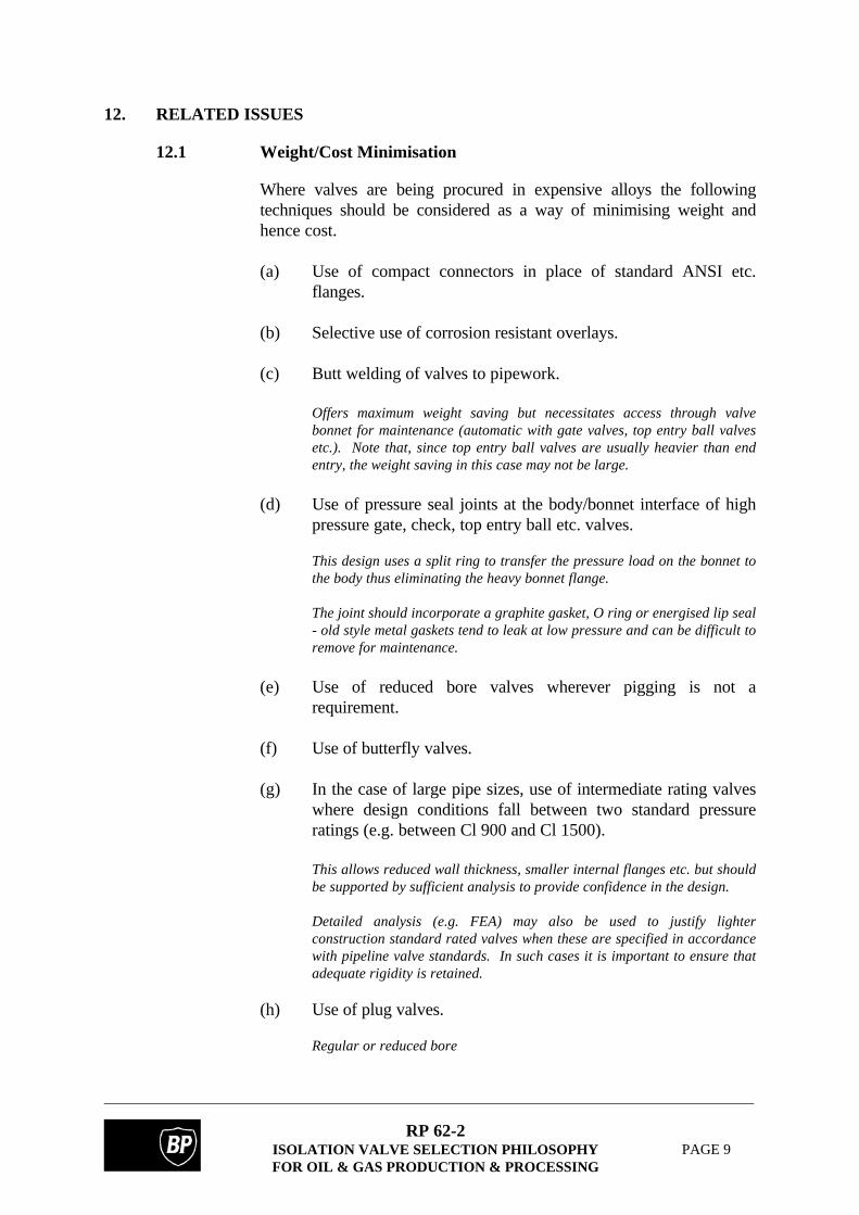
12. RELATED ISSUES
12.1 Weight/Cost Minimisation
Where valves are being procured in expensive alloys the followingtechniques should be considered as a way of minimising weight andhence cost.
(a) Use of compact connectors in place of standard ANSI etc.flanges.
(b) Selective use of corrosion resistant overlays.
(c) Butt welding of valves to pipework.
Offers maximum weight saving but necessitates access through valvebonnet for maintenance (automatic with gate valves, top entry ball valvesetc.). Note that, since top entry ball valves are usually heavier than endentry, the weight saving in this case may not be large.
(d) Use of pressure seal joints at the body/bonnet interface of highpressure gate, check, top entry ball etc. valves.
This design uses a split ring to transfer the pressure load on the bonnet tothe body thus eliminating the heavy bonnet flange.
The joint should incorporate a graphite gasket, O ring or energised lip seal- old style metal gaskets tend to leak at low pressure and can be difficult toremove for maintenance.
(e) Use of reduced bore valves wherever pigging is not arequirement.
(f) Use of butterfly valves.
(g) In the case of large pipe sizes, use of intermediate rating valveswhere design conditions fall between two standard pressureratings (e.g. between Cl 900 and Cl 1500).
This allows reduced wall thickness, smaller internal flanges etc. but shouldbe supported by sufficient analysis to provide confidence in the design.
Detailed analysis (e.g. FEA) may also be used to justify lighterconstruction standard rated valves when these are specified in accordancewith pipeline valve standards. In such cases it is important to ensure thatadequate rigidity is retained.
(h) Use of plug valves.
Regular or reduced bore

RP 62-2ISOLATION VALVE SELECTION PHILOSOPHYFOR OIL & GAS PRODUCTION & PROCESSING
PAGE 10
(i) Use of a single valve (e.g. expanding gate) to provide doubleblock and bleed isolation instead of two independent valves.
12.2 Vent/Drain etc. Plugs
Taper threaded valve body plugs and needle type 'vent' plugs are acommon cause of leakage incidents on gas production systems. This isusually due to a mixture of crevice etc. corrosion and poor mechanicalstrength (excessive PTFE tape application etc.). Where valve bodyconnections are necessary for operational/testing reasons on larger sizevalves consider terminating them with a blank flange or a flange + blockand bleed valve arrangement (see ESD above). Where not necessaryfor operational reasons they should be eliminated (in this case,manufacturer's claims that such body penetrations are necessary tofacilitate manufacture should be challenged).
Technical Bulletin TB 0005 (available from the custodian of this BP GroupRecommended Practice) provides guidance on this subject.
The same considerations apply to sealant injection fittings. Seat sealantinjection can sometimes assist in achieving a single isolation with a softseated ball valve but this operational advantage should be carefullyweighed against the number of additional potential leak paths beingintroduced. Where used, fittings which incorporate double seatedcheck valves may offer improved integrity.
12.3 Seal selection
O ring (or other elastomer type) seals in valves on high pressure gasservice must have:
(a) good resistance to the process fluids, dosing chemicals etc.
and
(b) maximum resistance to explosive decompression.
Special formulations are available for use at pressures above 70barwhich have a relatively high hardness and include a filler to reduce gaspermeability. These must be used with high strength, plastic back-uprings having low extrusion potential and scarf-cut joints.
At lower pressures high hardness will assist in resisting decompressiondamage.
It should be noted that, in the case of rings having section diametersabove approx. 6 mm, it is very difficult to preclude e.d. damage unlessdecompression rates are very low - regardless of material formulation.

RP 62-2ISOLATION VALVE SELECTION PHILOSOPHYFOR OIL & GAS PRODUCTION & PROCESSING
PAGE 11
In the case of very large ring sections damage may be inevitable owingto the difficulty of avoiding manufacturing defects. Such seals shouldbe avoided where possible and alternatives (re-inforced plastic lip seals,metal seals etc.) considered instead.
Valve suppliers knowledge of these considerations varies widely and seal selectionsshould be reviewed against the recommendations of ESR.93.ER.151 (BPExploration's Elastomer Selection Guidelines) and ESR.93.ER.124 (AvoidingExplosive Decompression damage in Seals), both available from the custodian ofthis Recommended Practice.
12.4 Fugitive Emissions
There is currently great interest in reducing fugitive emissions ofvolatile organic compounds from land based plants, the drivers beingboth environmental and economic (loss control). Whilst the economicfactors may be less significant offshore (especially where gas is notbeing exported) the environmental concerns are similar and ways inwhich losses can be minimised should be considered at the design stage.
Because of the general activity in this area it should be possible to take advantageof improved performance at little or no increase in cost.
Site surveys of conventional plant generally indicate that rising stem (globe type)control valves are the worst culprits followed by rising stem (e.g. gate and globe)isolating valves (note that small valves are often worse than larger sizes) withconventional quarter turn valves (ball and plug) giving fewer problems. This is nota surprising result.
Valve gland packings are a major source of these emissions and BP hasbeen conducting tests over a number years (principally on behalf of BPOil and BP Chemicals) in order to obtain an understanding of theproblem and explore possible solutions.
Tests on rising stem gate/globe (block valve) packings showed that:
1. all graphite packings perform better than asbestos;
2. that some quite simple low to medium density packings can givevery good performance;
3. that the best performance was obtained from an "engineered"design of packing with some pressure energising capability(Garlok EVSP 9000);
4. that graphite packings generally are relatively insensitive to stemdamage;
5. that stem straightness and runout must be carefully controlled;
RP 62-2ISOLATION VALVE SELECTION PHILOSOPHYFOR OIL & GAS PRODUCTION & PROCESSING
PAGE 12
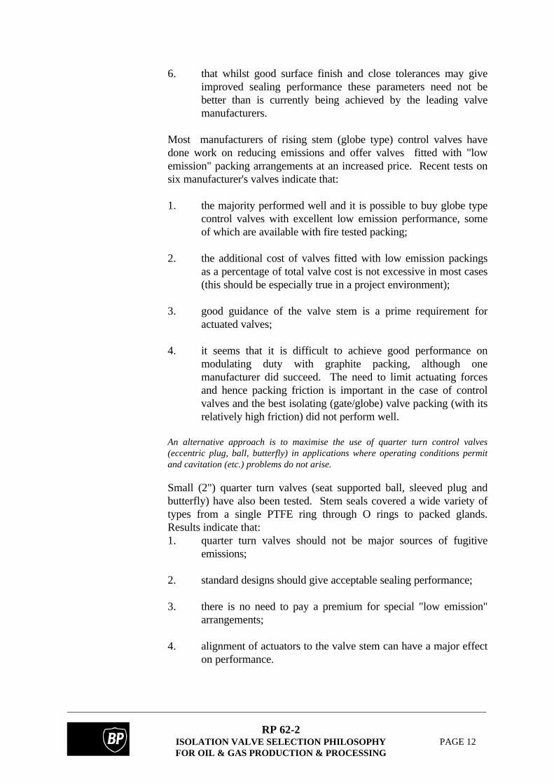
6. that whilst good surface finish and close tolerances may giveimproved sealing performance these parameters need not bebetter than is currently being achieved by the leading valvemanufacturers.
Most manufacturers of rising stem (globe type) control valves havedone work on reducing emissions and offer valves fitted with "lowemission" packing arrangements at an increased price. Recent tests onsix manufacturer's valves indicate that:
1. the majority performed well and it is possible to buy globe typecontrol valves with excellent low emission performance, someof which are available with fire tested packing;
2. the additional cost of valves fitted with low emission packingsas a percentage of total valve cost is not excessive in most cases(this should be especially true in a project environment);
3. good guidance of the valve stem is a prime requirement foractuated valves;
4. it seems that it is difficult to achieve good performance onmodulating duty with graphite packing, although onemanufacturer did succeed. The need to limit actuating forcesand hence packing friction is important in the case of controlvalves and the best isolating (gate/globe) valve packing (with itsrelatively high friction) did not perform well.
An alternative approach is to maximise the use of quarter turn control valves(eccentric plug, ball, butterfly) in applications where operating conditions permitand cavitation (etc.) problems do not arise.
Small (2") quarter turn valves (seat supported ball, sleeved plug andbutterfly) have also been tested. Stem seals covered a wide variety oftypes from a single PTFE ring through O rings to packed glands.Results indicate that:1. quarter turn valves should not be major sources of fugitive
emissions;
2. standard designs should give acceptable sealing performance;
3. there is no need to pay a premium for special "low emission"arrangements;
4. alignment of actuators to the valve stem can have a major effecton performance.
RP 62-2ISOLATION VALVE SELECTION PHILOSOPHYFOR OIL & GAS PRODUCTION & PROCESSING
PAGE 13
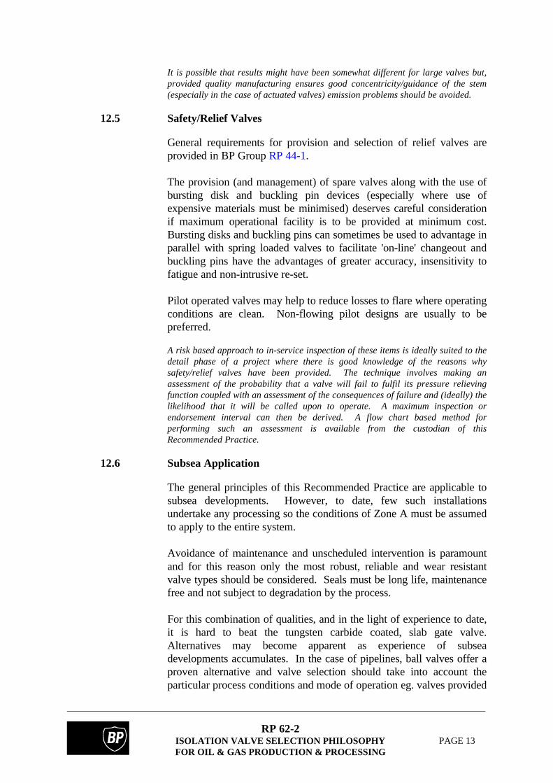
It is possible that results might have been somewhat different for large valves but,provided quality manufacturing ensures good concentricity/guidance of the stem(especially in the case of actuated valves) emission problems should be avoided.
12.5 Safety/Relief Valves
General requirements for provision and selection of relief valves areprovided in BP Group RP 44-1.
The provision (and management) of spare valves along with the use ofbursting disk and buckling pin devices (especially where use ofexpensive materials must be minimised) deserves careful considerationif maximum operational facility is to be provided at minimum cost.Bursting disks and buckling pins can sometimes be used to advantage inparallel with spring loaded valves to facilitate 'on-line' changeout andbuckling pins have the advantages of greater accuracy, insensitivity tofatigue and non-intrusive re-set.
Pilot operated valves may help to reduce losses to flare where operatingconditions are clean. Non-flowing pilot designs are usually to bepreferred.
A risk based approach to in-service inspection of these items is ideally suited to thedetail phase of a project where there is good knowledge of the reasons whysafety/relief valves have been provided. The technique involves making anassessment of the probability that a valve will fail to fulfil its pressure relievingfunction coupled with an assessment of the consequences of failure and (ideally) thelikelihood that it will be called upon to operate. A maximum inspection orendorsement interval can then be derived. A flow chart based method forperforming such an assessment is available from the custodian of thisRecommended Practice.
12.6 Subsea Application
The general principles of this Recommended Practice are applicable tosubsea developments. However, to date, few such installationsundertake any processing so the conditions of Zone A must be assumedto apply to the entire system.
Avoidance of maintenance and unscheduled intervention is paramountand for this reason only the most robust, reliable and wear resistantvalve types should be considered. Seals must be long life, maintenancefree and not subject to degradation by the process.
For this combination of qualities, and in the light of experience to date,it is hard to beat the tungsten carbide coated, slab gate valve.Alternatives may become apparent as experience of subseadevelopments accumulates. In the case of pipelines, ball valves offer aproven alternative and valve selection should take into account theparticular process conditions and mode of operation eg. valves provided

RP 62-2ISOLATION VALVE SELECTION PHILOSOPHYFOR OIL & GAS PRODUCTION & PROCESSING
PAGE 14
to facilitate tie-ins are often required to seal until after the tie-in is madethen function as a piece of pipe. Soft seated valves supplied (and left)in the closed position may be most suitable for this service. Othervalves (eg. associated with pigging operations) will need to be debristolerant to provide repeatable sealing over a long life. All valves willhave to survive flushing and line clearing (see above) and may need tobe protected during these operations.

RP 62-2ISOLATION VALVE SELECTION PHILOSOPHYFOR OIL & GAS PRODUCTION & PROCESSING
PAGE 15
SYSTEM/ ZONEDESCRIPTION
PRESSURE TEMPERATURE NOTES & ASSUMPTIONS RE.SERVICE CONDITIONS
(A) Flowlines,Diverters, Manifoldsetc.Import & InfieldPipelines
< 200 bar (oil)< 500 bar gas
< 150°C Usual case is gas/oil/watermixture. In the case of newdevelopments it should always beassumed that sand will be present(dirty service).
(B) Stabilisation/Processing(liquid line) Stage 1 Stage 2
10-90 bar< 10 bar
< 150°C< 80°C
2 Phase flow after interstagecontr. valve. Still some sand/water until after LP separator.De-salters (where provided)assumed to come after LP sep. -treat as "export oil".
(C) Produced Water(upstream of settlingtanks)
< 90 bar reducingthrough system
< 150°C at HPseparator coolingthereafter
Usually high sand content & canbe very corrosive. Sandtreatment can involve high cycleabrasive service.
(D) Export Oil 2 - 250 bar < 60°C 0.5 to 2% water (max.) by wt.Relatively sweet even on sourservice.
(E) Gas from HPseparator
<90 bar < 150°C Wet & dirty initially.Clean service after scrubbers.
(F) Gas from LPseparator
< 10 bar beforecompression.
< 80°C Wet but generally clean exceptwhere high sand content inproduct.Clean service after scrubbers.
(G) Gas Treatment(drying, sweeteningetc.) Mol. Sieves Glycol, sweetening Dew point proc.
< 80 bar < 100°C
< 300°C< 200°C- 30/40°C min.
Generally clean service but somedryers (e.g. mol. sieves) canintroduce abrasive particles.Switching valves subject to highcycle wear. Potential for lowtemperatures exists (-20°C)throughout gas system.
(H) Export gas < 170 bar < 120°C at comp.outlet,<60°C at exp
Clean service but valvesassociated with piggingoperations may see abrasivedebris and flow at highdifferential pressure.
TABLE 1. ASSUMED CONDITIONS FOR OIL AND GAS PROCESSING

RP 62-2ISOLATION VALVE SELECTION PHILOSOPHYFOR OIL & GAS PRODUCTION & PROCESSING
PAGE 16
(I) Gas re-injection < 350 bar < 150°C Clean service and dry but may bewet where corrosion etc. not aproblem.
(J) Lift gas < 350 bar < 150°C Clean service. Dry if highpressure, otherwise may be wet.
(K) Fuel gas < 80 bar < 100°C Clean service and usually dry.(L) Vent/ Flare/Relief H.P.Flare
L.P. Flare
< 12 bar
< 1.5 bar
-100°C min (gas)-40°C min (oil)< 60°C
Clean service.
(M) Condensereturns
As for main system As for mainsystem
Condense from HP & LPscrubbers etc. assumed to bedirty.Condense from dryers &downstream scrubbers etc.assumed to be clean.
(N) Open Drains As for main system As for mainsystem
Only used for wash out/ purgewith water or N2. Not onerousservice.
(O) Closed drains As for main system As for mainsystem
Assume dirty service where thisassumption is made for associatedsystem
(P) Water Injection < 250 bar < 20°C Filtered at LP and sand free afterpressurisation.
Notes:
When making selections for wet gas systems the erosion/corrosion potential of entrained liquidshould be considered.
TABLE 1. ASSUMED CONDITIONS FOR OIL AND GAS PROCESSING (CONT.)

RP 62-2ISOLATION VALVE SELECTION PHILOSOPHYFOR OIL & GAS PRODUCTION & PROCESSING
PAGE 17
ZONE PRIMARYRECOMMENDATION
COMMENTS & ALTERNATIVES(Notes)
A Slab type gate, tungsten carbide(WC) coated;Trunnion ball, WC coated;
These will be comparably priced. Both canhandle service but gate v. will give betterisolation. (1)Acceptable Alternatives: (2)Stellite coated balanced plug; (3)Rotating disk ("Everlasting"); (3)Eccentric ball ("Orbit");Semi-balanced plug ("Texsteam" - limitedrange). (3)Axial piston (Mokveld)Note: In the case of infrequently operatedvalves in pipelines where sand content islow, soft seated trunnion ball valves may bepossible provided they receive adequateprotection during installation/flushing etc.
B Slab type gate, WC coated;Trunnion ball, WC coated
Where sand content low, Stage 2 may betreated as D below.Acceptable AlternativesIf sand exists for only very limited period,ENP coated gate valve may offer necessaryabrasion resistance combined with goodisolation at economic cost; (4)Stellite coated balanced plug;Sleeved plug (possible for lower pressureratings and smaller sizes but ideally needregular exercising);Other alternatives as for zone A.(See below for import line ESDV and pigtrap applications.)
C Rotating disk ('everlasting');Balanced plug, stellite coated;Semi-balanced plug;Trunnion ball, WC coated;Slab gate WC coated.
All types need careful materialselection/corrosion protection.Acceptable AlternativesEccentric ball;Wedge gate if little sand;Sleeved plug for lower pressure ratings (butideally need exercising regularly);
TABLE 2. ISOLATING/BLOCK VALVE RECOMMENDATIONS

RP 62-2ISOLATION VALVE SELECTION PHILOSOPHYFOR OIL & GAS PRODUCTION & PROCESSING
PAGE 18
D Applications other than pigtrap isolation:Trunnion ball, soft seated;Wedge gate (smaller sizes).Pig trap isolation valves (seesection 11.2):Slab gate; (ENP or WCcoated)Expanding gate;Trunnion ball, WC coated.
Acceptable AlternativesGiven appropriate material selection, mosthigh pressure valve types listed above wouldbe acceptable for the non-pig trap isolationservice.
E1(prior toknock-
out)
Slab gate;Trunnion Ball, WC coated;Stellite coated balanced plug.
ENP coated gate could offer necessaryabrasion resistance at economic cost. (4)
E1(after
knock-out)
Trunnion ball, soft seated;Wedge gate;Slab gate, ENP coated.
Acceptable alternativesButterfly (< Cl 600)ENP coated balanced plug (4)
F Trunnion ball, soft seated (seatsupported ≤ 6");Wedge gate;Slab gate, ENP coated; (4)
Acceptable alternativesButterfly;ENP coated balanced plug. (4)Sleeved plug (smaller sizes)
G Trunnion ball, soft seated;Wedge gate;Slab gate, ENP coated; (4)
Switching/recycle valves associated withsome gas dryers must withstand high cyclewear e.g.Trunnion ball, WC coated;Eccentric ball;Balanced plug, stellite coated;Rotating disc.High and low temperatures will affectselection.Acceptable alternativesButterfly (≤ Cl 600);ENP coated balanced plug. (4)
TABLE 2. ISOLATING/BLOCK VALVE RECOMMENDATIONS (CONT.)
RP 62-2ISOLATION VALVE SELECTION PHILOSOPHYFOR OIL & GAS PRODUCTION & PROCESSING
PAGE 19
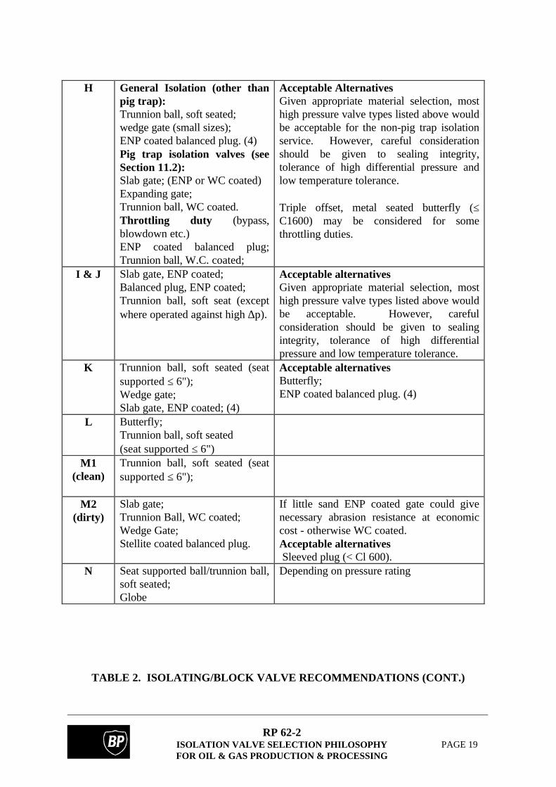
H General Isolation (other thanpig trap):Trunnion ball, soft seated;wedge gate (small sizes);ENP coated balanced plug. (4)Pig trap isolation valves (seeSection 11.2):Slab gate; (ENP or WC coated)Expanding gate;Trunnion ball, WC coated.Throttling duty (bypass,blowdown etc.)ENP coated balanced plug;Trunnion ball, W.C. coated;
Acceptable AlternativesGiven appropriate material selection, mosthigh pressure valve types listed above wouldbe acceptable for the non-pig trap isolationservice. However, careful considerationshould be given to sealing integrity,tolerance of high differential pressure andlow temperature tolerance.
Triple offset, metal seated butterfly (≤C1600) may be considered for somethrottling duties.
I & J Slab gate, ENP coated;Balanced plug, ENP coated;Trunnion ball, soft seat (exceptwhere operated against high ∆p).
Acceptable alternativesGiven appropriate material selection, mosthigh pressure valve types listed above wouldbe acceptable. However, carefulconsideration should be given to sealingintegrity, tolerance of high differentialpressure and low temperature tolerance.
K Trunnion ball, soft seated (seatsupported ≤ 6");Wedge gate;Slab gate, ENP coated; (4)
Acceptable alternativesButterfly;ENP coated balanced plug. (4)
L Butterfly;Trunnion ball, soft seated(seat supported ≤ 6")
M1(clean)
Trunnion ball, soft seated (seatsupported ≤ 6");
M2(dirty)
Slab gate;Trunnion Ball, WC coated;Wedge Gate;Stellite coated balanced plug.
If little sand ENP coated gate could givenecessary abrasion resistance at economiccost - otherwise WC coated.Acceptable alternatives Sleeved plug (< Cl 600).
N Seat supported ball/trunnion ball,soft seated;Globe
Depending on pressure rating
TABLE 2. ISOLATING/BLOCK VALVE RECOMMENDATIONS (CONT.)

RP 62-2ISOLATION VALVE SELECTION PHILOSOPHYFOR OIL & GAS PRODUCTION & PROCESSING
PAGE 20
O As for main system Acceptable alternatives- Sleeved Plug ((<CL600) for dirty service- Globe
P Trunnion ball, soft seated (exceptwhere operated against high ∆por water not sand free, in whichcase see I & J above)
Acceptable alternativesButterfly in L.P.Wedge gate.
Notes:
(1) It is sometimes difficult to accommodate slab gate valves in existing piping systems because of their heightbut this should never be a problem with a new development where the design contractor should considertheir use from the outset.
(2) Suppliers of valves intended for dirty service should have demonstrated good performance in a type testconducted by BP or NEL unless there is sufficient operating experience in similar service to giveconfidence of successful application.
(3) Particularly suited to frequent operation and higher sand content.
(4) Electroless nickel plating is porous as is chrome plating. Base material selections must exhibit adequateresistance to corrosion by the working fluid.
TABLE 2. ISOLATING/BLOCK VALVE RECOMMENDATIONS (CONT.)

RP 62-2ISOLATION VALVE SELECTION PHILOSOPHYFOR OIL & GAS PRODUCTION & PROCESSING
PAGE 21
ZONE ≤ 2" NPS ( DN 50) > 2" NPS (DN 50)A Ball check, hard faced,
straight or "Y" pattern (1)Duo-disk wafer check, hard faced or rubberseated with metal back-up.Acceptable AlternativesSwing check, hard faced; (2)Axial flow "non-slam" check; (3)Tilting disk check. (3)
B As for zone A As for zone AC Ball check, hard faced, straight or
"Y" pattern (1);Diaphragm check.
Duo-disk wafer check, hard faced or rubberseated with metal back-up;Swing check. (2)
D Piston check. (1) Duo-disk wafer check;Swing check.
E1(prior toknock-out)
Ball check; (1) Duo-disk wafer check, hard-faced or rubberseated with metal back-up;Acceptable alternativeSwing Check
E2(afterknock-out)
Piston check; (1) Duo-disk wafer check.Acceptable alternativeSwing check
F As for E2 As for E2G As for E2 Duo-disk wafer check.
Acceptable alternativeAxial flow check.
H As for E2 Axial flow check (4)Duo-disk wafer check;Tilting disk check.
I & J As for H As for HK As for H As for HL As for H Duo-disk wafer check.M1(clean)
Piston check;Ball check. (1)
Duo-disk wafer check;Swing check.
M2(dirty)
Ball check (1) Duo-disk wafer check, hard faced or rubber seatwith metal back-up;Swing check, hard faced.
N Piston/Ball check (1) Swing checkO As for main system As for main systemP Piston/Ball check (1) Duo-disk wafer check;
Swing checkNotes:(1) Where "in line" type ball or piston check valves are used in horizontal pipes they must be fitted
with a closing spring. Consider piston type where frequent flow/pressure variations expected.(2) Wafer style, single disk check valves are not recommended.(3) Usually only to satisfy diversity requirements in this service.(4) Must be used at outlet of reciprocating compressors
TABLE 3. CHECK VALVE RECOMMENDATIONS

RP 62-2ISOLATION VALVE SELECTION PHILOSOPHYFOR OIL & GAS PRODUCTION & PROCESSING
PAGE 22
APPENDIX A
DEFINITIONS AND ABBREVIATIONS
Definitions
Standard definitions may be found in the BP Group RPSEs Introductory Volume.
Abbreviations
ANSI American National Standards Institute
CAPEX Capital Expenditure
DN Nominal Diameter
EEMUA Engineering Equipment and Material Users Association
ENP Electroless Nickel Plate
ESD Emergency Shutdown
ESDV Emergency Shutdown Valve
FEA Finite Element Analysis
NEL Ltd Formally National Engineering Laboratory
NPS Nominal Pipe Size
PTFE Polytetrafluoroethylene
WC Tungsten carbide

RP 62-2ISOLATION VALVE SELECTION PHILOSOPHYFOR OIL & GAS PRODUCTION & PROCESSING
PAGE 23
APPENDIX B
LIST OF REFERENCED DOCUMENTS
A reference invokes the latest published issue or amendment unless stated otherwise.
Referenced standards may be replaced by equivalent standards that are internationally orotherwise recognised provided that it can be shown to the satisfaction of the purchaser'sprofessional engineer that they meet or exceed the requirements of the referenced standards.
BP Documents
BP Group RP 62-1 Guide to Valve Selection
BP Group RP 30-3 Instrument and Control - Selection and use of Control andShutoff Valves.
BP Group RP 44-1 Overpressure Protection Systems
BP Group RP 44-10 Isolation of Equipment for Maintenance
BP Group GS 130-6 Actuators for Shut-off Valves
BP Group GS 134-1 Hydraulic Power Supplies
BP Group ESR.93.ER.151 Elastomar Selection Guidelines
BP Group ESR.93.ER.124 Avoiding Explosive Decompression damage in Seals
BP Group TB0005 Auxiliary Connections in Valve Bodies
BP Sunbury Branch The Protection of Valve Seat during Commissioning by use ofReport 124 240 Silicon Sealant
Others
EEMUA 182 Specification & Application Guidelines for Integral Block &Bleed Valve Manifolds for Direct Connection to Pipework.