ISOIL ML110 CONVERTER For use with ELECTROMAGNETIC...
45
Flomotion Systems Inc. 800.909.3569 FlomotionSystems.com ML 110 Operating & Maintenance Manual 1 ISOIL ML110 CONVERTER For use with ELECTROMAGNETIC FLOWMETERS
Transcript of ISOIL ML110 CONVERTER For use with ELECTROMAGNETIC...

Flomotion Systems Inc. 800.909.3569 FlomotionSystems.com ML 110 Operating & Maintenance Manual
1
ISOIL ML110 CONVERTER For use with
ELECTROMAGNETIC FLOWMETERS

Flomotion Systems Inc. 800.909.3569 FlomotionSystems.com ML 110 Operating & Maintenance Manual
2

Flomotion Systems Inc. 800.909.3569 FlomotionSystems.com ML 110 Operating & Maintenance Manual
3
ML110 CONVERTER MANUAL
Including Installation Instructions for
M/MS SERIES ELECTROMAGNETIC FLOWMETERS
March 2005 VER 3.0x
ML 110 - Version 3.0X
The software version is displayed when powering up the converter.

Flomotion Systems Inc. 800.909.3569 FlomotionSystems.com ML 110 Operating & Maintenance Manual
4
FLOMOTION SYSTEMS, Inc. 586 N. French Rd., Suite 6 Buffalo, NY 14228-2103
Toll Free: 800.909.FLOW (3569) (USA & Canada only)
Phone: 716.691.3941 Fax: 716.691.1253
Email: [email protected]

Flomotion Systems Inc. 800.909.3569 FlomotionSystems.com ML 110 Operating & Maintenance Manual
5
INTRODUCTION
• This manual is an integral part of the product. Please read carefully since it contains important information for the safe use and maintenance of the equipment.
• The technical information and the relative products of this manual are subject to change without notice. • The flow meter must be used for the use it has been built for. The improper use or tampering of the instrument or
parts of it and substitutions of any components not original makes the warranty void. • The manufacturer is considered responsible only if the instrument in used in its original configuration.
The manual is presented in two sections: Section 1: SENSORS Section 2: CONVERTERS

Flomotion Systems Inc. 800.909.3569 FlomotionSystems.com ML 110 Operating & Maintenance Manual
6
DECLARATION OF CONFORMITY
According to ISO / IEC Guide 22 and EN 45014 Product’s name: Electromagnetic flow meter Converter model: ML100 – ML110 (HV, LV versions) Option: all applicable Sensor model: M501 - MS 501 - MS 1000 - MS 2410 - MS 2500 - MS 3700 - MS 3770
ISOIL INDUSTRIA S.P.A. declares that the above-mentioned products satisfy the following requirements: Safety: EN61010, dielectric strength = 4 kV, installation category II, IP67 EMC:
EN55011 (150 kHz – 30 MHz): Group 1, Class B EN55011 (30 MHz – 1GHz): Group 1, Class B IEC 1000-4-2: 6 kV CD, 8 kV AD IEC 1000-4-3 (f = 80 MHz – 1 GHz, antenna at 3 m, AM modulation 1kHz 80%): 10 V/m IEC 1000-4-3 (f = 900MHz, antenna at 3 m, AM modulation 200 Hz 100%): 10 V/m IEC 1000-4-4: 4 kV on all ports IEC 1000-4-5: (2kV differential / 4kV common mode) on main supply port IEC 1000-4-6 (f = 150 kHz – 80 MHz, AM modulation 1 kHz 80%): 10 V IEC 1000-4-11
Flomotion Systems Inc. 800.909.3569 FlomotionSystems.com ML 110 Operating & Maintenance Manual
7
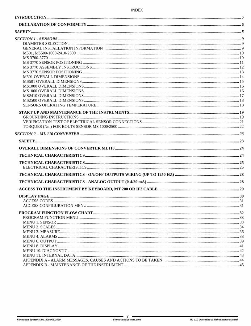
INDEX
INTRODUCTION............................................................................................................................................................................................ 5 DECLARATION OF CONFORMITY..................................................................................................................................................... 6
SAFETY ........................................................................................................................................................................................................... 8 SECTION 1 - SENSORS ................................................................................................................................................................................. 9
DIAMETER SELECTION ....................................................................................................................................................................... 9 GENERAL INSTALLATION INFORMATION ..................................................................................................................................... 9 M501, MS500-1000-2410-2500 ............................................................................................................................................................. 10 MS 3700-3770 ........................................................................................................................................................................................ 10 MS 3770 SENSOR POSITIONING ....................................................................................................................................................... 11 MS 3770 ASSEMBLY INSTRUCTIONS.............................................................................................................................................. 12 MS 3770 SENSOR POSITIONING ....................................................................................................................................................... 13 M501 OVERALL DIMENSIONS.......................................................................................................................................................... 14 MS501 OVERALL DIMENSIONS........................................................................................................................................................ 15 MS1000 OVERALL DIMENSIONS...................................................................................................................................................... 16 MS1000 OVERALL DIMENSIONS...................................................................................................................................................... 16 MS2410 OVERALL DIMENSIONS...................................................................................................................................................... 17 MS2500 OVERALL DIMENSIONS...................................................................................................................................................... 18 SENSORS OPERATING TEMPERATURE.......................................................................................................................................... 18
START UP AND MAINTENANCE OF THE INSTRUMENTS.......................................................................................................... 19 GROUNDING INSTRUCTIONS........................................................................................................................................................... 19 VERIFICATION TEST OF ELECTRICAL SENSOR CONNECTIONS.............................................................................................. 21 TORQUES (Nm) FOR BOLTS SENSOR MS 1000/2500 ..................................................................................................................... 22
SECTION 2 – ML 110 CONVERTER .......................................................................................................................................................... 23 SAFETY..................................................................................................................................................................................................... 23 OVERALL DIMENSIONS OF CONVERTER ML110........................................................................................................................ 24 TECHNICAL CHARACTERISTICS..................................................................................................................................................... 24 TECHNICAL CHARACTERISTICS..................................................................................................................................................... 25
ELECTRICAL CHARACTERISTICS................................................................................................................................................... 25 TECHNICAL CHARACTERISTICS - ON/OFF OUTPUTS WIRING (UP TO 1250 HZ) .............................................................. 28 TECHNICAL CHARACTERISTICS - ANALOG OUTPUT (0-4/20 mA) ......................................................................................... 28 ACCESS TO THE INSTRUMENT BY KEYBOARD, MT 200 OR IF2 CABLE .............................................................................. 29 DISPLAY PAGE....................................................................................................................................................................................... 30
ACCESS CODES ................................................................................................................................................................................... 31 ACCESS CONFIGURATION MENU ................................................................................................................................................... 31
PROGRAM FUNCTION FLOW CHART............................................................................................................................................. 32 PROGRAM FUNCTION MENU........................................................................................................................................................... 33 MENU 1. SENSOR ................................................................................................................................................................................ 33 MENU 2. SCALES................................................................................................................................................................................. 34 MENU 3. MEASURE............................................................................................................................................................................. 36 MENU 4. ALARMS ............................................................................................................................................................................... 38 MENU 6. OUTPUT................................................................................................................................................................................ 39 MENU 8. DISPLAY............................................................................................................................................................................... 41 MENU 10. DIAGNOSTIC ..................................................................................................................................................................... 42 MENU 11. INTERNAL DATA.............................................................................................................................................................. 43 APPENDIX A - ALARM MESSAGES, CAUSES AND ACTIONS TO BE TAKEN.......................................................................... 44 APPENDIX B - MAINTENANCE OF THE INSTRUMENT ............................................................................................................... 45
Flomotion Systems Inc. 800.909.3569 FlomotionSystems.com ML 110 Operating & Maintenance Manual
8
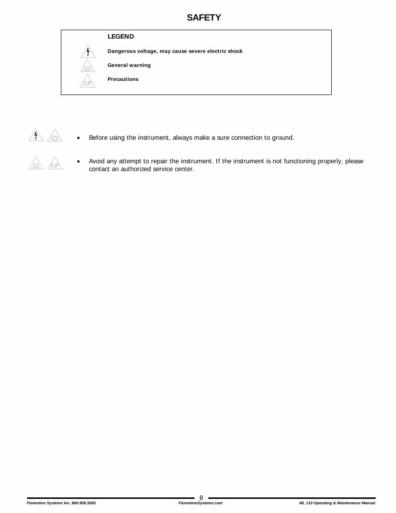
SAFETY
LEGEND
• Before using the instrument, always make a sure connection to ground.
• Avoid any attempt to repair the instrument. If the instrument is not functioning properly, please
contact an authorized service center.
Dangerous voltage, may cause severe electric shock
General warning
Precautions

Flomotion Systems Inc. 800.909.3569 FlomotionSystems.com ML 110 Operating & Maintenance Manual
9
SECTION 1 - SENSORS
DIAMETER SELECTION The suitable nominal diameter can be determined by means of the tables at left. The flow velocity is also determined by the fluid properties: - For “aqueous” solutions, full-scale velocity should be within: 1 to 33 fps - For fluids tending to form deposits within the measuring section velocity should be above 6.5 fps. - For abrasive fluids the velocity must be less than 6.5 fps.
GENERAL INSTALLATION INFORMATION
Flow direction
?
Before installing the sensor determine the direction of the liquid in the pipe.
- FLOW DIRECTION +
The sign of the flow rate is positive, when the flow direction is moving from – to + as printed on the direction tag. If after installation it becomes necessary to reverse the sign of the flow, it is sufficient to reverse the sign of the coefficient (Ka). See the converter instructions in section 1 of this manual.
////
Before tightening the flange nuts make sure that the ends of the sensor are coaxial to those of the pipe.
The Eye Hooks are provided To fully support the weight of the sensor.
Recommended lifting method
Before lifting, make sure the cylinders are on the centerline of the sensor.
Method of lifting recommended for all sensors equipped with eyebolt. For the MS 1000 sensor we recommend the use of centering cylinders (available on request).

Flomotion Systems Inc. 800.909.3569 FlomotionSystems.com ML 110 Operating & Maintenance Manual
10
Avoid installation near curves or hydraulic accessories.
M501, MS500-1000-2410-2500
MS 3700-3770
Install the sensor away from curves and hydraulic accessories.
During operation the pipe must be completely full of liquid, or completely empty.
For vertical installations it is preferable to have an ascending flow.
For installations in long pipelines, please use anti-vibration joints.
Before tightening the nuts bring the flange of the piping and the flange of the sensor as close as possible.
Avoid use with the pipe partially empty.
For vertical installations with descending flow direction contact the manufacturer
Avoid the installation of the sensor in a long pipeline, without any support of the same.
Avoid drawing the flange and counter flange together using the closing force of the nuts.
ALWAYS AVOID 3 DN
2 DN
ANTI-VIBRATION JOINT
MAIN PIPELINE
SEPARATION <= 4mm
MAIN PIPELINE
Install the sensor away from curves and hydraulic accessories.
During operation the pipe must be completely full of liquid, or completely empty.
For vertical installations it is preferable to have an ascending flow.
Before opening the ball valve tighten the fixing nut.
Avoid installation near curves or hydraulic accessories.
Avoid operation with the pipe partially empty.
For vertical installations with descending flow direction contact the manufacturer.
Opening the ball valve before tightening the fixing nut could cause the expulsion of the sensor from the pipeline.
The illustrations in figures A-B-C-E-F-G are also valid for the MS 3770 insertion sensor.
ALWAYS TO AVOID 20 DN
15 DN
A
B
C
D
ATTENTION !!!
E
F
G
H

Flomotion Systems Inc. 800.909.3569 FlomotionSystems.com ML 110 Operating & Maintenance Manual
11
MS 3770 SENSOR POSITIONING
- Weld a 1"Ø pipe to the pipeline. ATTENTION: verify "X" dimension (pic. 2).
Pic. 1Pipe Ø 1"
Pipe line
Spanner 40mm
Screw the valve Ø 1" to the welded pipe
XXmax=140mm
- Screw the 1" jacket to the valve ATTENTION: the O-Ring in the jacket must be placed underside (near valve)
Interior cutaway ofthe jacket(O-Ring seal)
- Insert the sensor with valve closed - Tighten the fixing nut with wrench (pic. 6)
- Open the valve- Screw the sensor up to "Z" dimension- Verify that it lines up (pic. 9)- Tighten the block nut mantaining the aligment
flow
directio
n
Pic. 2
Pic. 3
Pic. 4
Pic. 5
Pic. 6
Pic. 7
Pic. 8
Pic. 9
Z
Blocknut
N.B.: The handles of the insertion sensor are removeable
sensorhandles
1
2
3
4
5
Fixing nut
Fixingnut
Flomotion Systems Inc. 800.909.3569 FlomotionSystems.com ML 110 Operating & Maintenance Manual
12
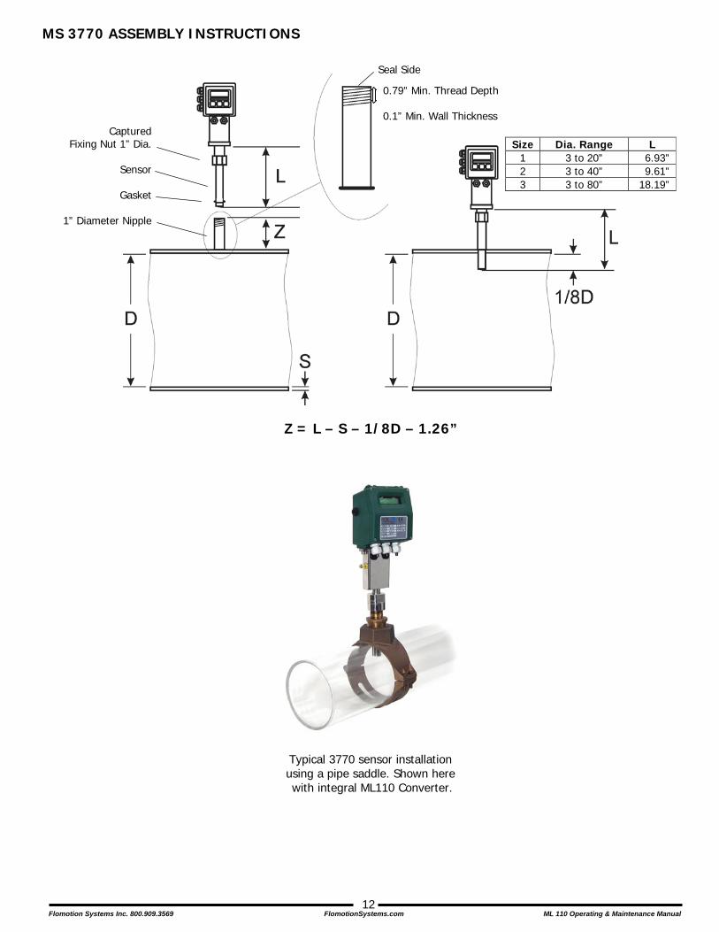
MS 3770 ASSEMBLY INSTRUCTIONS
Z = L – S – 1/8D – 1.26”
Typical 3770 sensor installation using a pipe saddle. Shown here with integral ML110 Converter.
Size Dia. Range L 1 3 to 20” 6.93” 2 3 to 40” 9.61” 3 3 to 80” 18.19”
Captured Fixing Nut 1” Dia.
Sensor
Gasket
1” Diameter Nipple
0.79” Min. Thread Depth 0.1” Min. Wall Thickness
Seal Side

Flomotion Systems Inc. 800.909.3569 FlomotionSystems.com ML 110 Operating & Maintenance Manual
13
MS 3770 SENSOR POSITIONING
Flow direction
Z
Pic. 1
Pic. 2
Pic. 3
Pic. 4
Pic. 5
Pic. 6
Nipple 1" Dia.
Process Pipe
Sensor
Gasket
Nipple 1" Dia.
Process Pipe
Wrench 40mm
zO
ver-m
etal
Cut the 1” installation nipple to the appropriate length (“Z”) based on the following:
Z = L – S – 1/8D - 1.26 Where: L=Sensor Length S=Wall Thickness D=Inside Dia. Of Process Pipe
Weld the nipple to the process pipe (or thread it on if using a Thread-O-Let or saddle).
If the nipple is to be welded onto the process pipe leave one end unthreaded. For mounting on a Thread-O-Let or saddle both ends must be threaded.
Insert the sensor through the 1” nipple. Be sure to install the gasket.
Align the connector box on the sensor with the process pipe as shown in pic. 6. Tighten the sensor fixing nut (pic. 5) while maintaining the alignment of the sensor. The sensor fixing nut must be tightened sufficiently to seal the gasket.

Flomotion Systems Inc. 800.909.3569 FlomotionSystems.com ML 110 Operating & Maintenance Manual
14
M501 OVERALL DIMENSIONS
Sensor Size (D above) CHARACTERISTICS 1/8" 1/4" 1/2" 3/4" 1" Minimum Flow (gpm @ 1 ft/s) .06 0.14 0.85 1.52 2.37 Maximum Flow (gpm @ 33 ft/s) 1.12 4.49 28.03 49.84 77.87 Process Connectors (FNPT) 1/4" 3/8" 3/4" 3/4" 1"

Flomotion Systems Inc. 800.909.3569 FlomotionSystems.com ML 110 Operating & Maintenance Manual
15
MS501 OVERALL DIMENSIONS
Sensor Size CHARACTERISTICS 1/8" 1/4" 3/8" 1/2" 3/4" Min flow rate (gpm @ 1 ft/sec) 0.034 0.14 0.38 0.85 1.52 Max flow rate (gpm @ 33 ft/sec) 1.12 4.49 12.46 28.03 49.84 Weight (lbs.) 4.85 4.85 4.85 4.85 4.85 Length (L above) w/Tri-Clamp Fittings 5.00 5.00 5.00 5.00 5.00 Length (L above) w/NPT Fittings 4.72 4.72 4.72 4.72 4.72
Flomotion Systems Inc. 800.909.3569 FlomotionSystems.com ML 110 Operating & Maintenance Manual
16
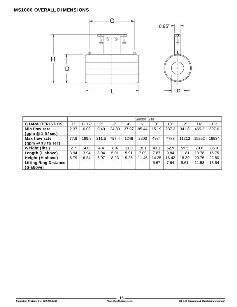
MS1000 OVERALL DIMENSIONS
Sensor Size CHARACTERISTICS 1” 1-1/2” 2” 3” 4” 6” 8” 10” 12” 14” 16” Min flow rate (gpm @ 1 ft/sec)
2.37 6.08 9.49 24.30 37.97 85.44 151.9 237.3 341.8 465.2 607.6
Max flow rate (gpm @ 33 ft/sec)
77.9 199.3 311.5 797.4 1246 2803 4984 7787 11213 15262 19934
Weight (lbs.) 2.7 4.0 4.4 8.4 11.0 18.1 40.1 52.9 59.5 70.6 86.0 Length (L above) 3.94 3.94 3.94 5.91 5.91 7.09 7.87 9.84 11.81 13.78 15.75 Height (H above) 5.79 6.34 6.97 8.23 9.25 11.46 14.25 16.42 18.39 20.75 22.80 Lifting Ring Distance (G above)
- - - - - - 5.67 7.64 9.61 11.58 13.54
Flomotion Systems Inc. 800.909.3569 FlomotionSystems.com ML 110 Operating & Maintenance Manual
17
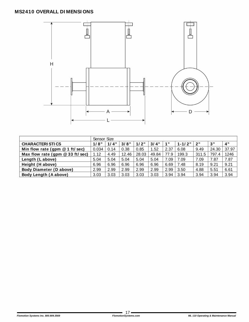
MS2410 OVERALL DIMENSIONS
Sensor Size CHARACTERISTICS 1/8” 1/4" 3/8” 1/2" 3/4" 1” 1-1/2” 2” 3” 4” Min flow rate (gpm @ 1 ft/sec) 0.034 0.14 0.38 0.85 1.52 2.37 6.08 9.49 24.30 37.97Max flow rate (gpm @ 33 ft/sec) 1.12 4.49 12.46 28.03 49.84 77.9 199.3 311.5 797.4 1246 Length (L above) 5.04 5.04 5.04 5.04 5.04 7.09 7.09 7.09 7.87 7.87 Height (H above) 6.96 6.96 6.96 6.96 6.96 6.69 7.48 8.19 9.21 9.21 Body Diameter (D above) 2.99 2.99 2.99 2.99 2.99 2.99 3.50 4.88 5.51 6.61 Body Length (A above) 3.03 3.03 3.03 3.03 3.03 3.94 3.94 3.94 3.94 3.94
Flomotion Systems Inc. 800.909.3569 FlomotionSystems.com ML 110 Operating & Maintenance Manual
18
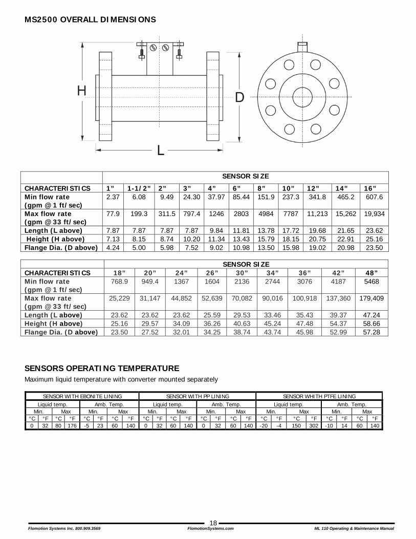
MS2500 OVERALL DIMENSIONS
SENSOR SIZE
CHARACTERISTICS 1” 1-1/2” 2” 3” 4” 6” 8” 10” 12” 14” 16” Min flow rate (gpm @ 1 ft/sec)
2.37 6.08 9.49 24.30 37.97 85.44 151.9 237.3 341.8 465.2 607.6
Max flow rate (gpm @ 33 ft/sec)
77.9 199.3 311.5 797.4 1246 2803 4984 7787 11,213 15,262 19,934
Length (L above) 7.87 7.87 7.87 7.87 9.84 11.81 13.78 17.72 19.68 21.65 23.62 Height (H above) 7.13 8.15 8.74 10.20 11.34 13.43 15.79 18.15 20.75 22.91 25.16 Flange Dia. (D above) 4.24 5.00 5.98 7.52 9.02 10.98 13.50 15.98 19.02 20.98 23.50 SENSOR SIZE CHARACTERISTICS 18” 20” 24” 26” 30” 34” 36” 42” 48” Min flow rate (gpm @ 1 ft/sec)
768.9 949.4 1367 1604 2136 2744 3076 4187 5468
Max flow rate (gpm @ 33 ft/sec)
25,229 31,147 44,852 52,639 70,082 90,016 100,918 137,360 179,409
Length (L above) 23.62 23.62 23.62 25.59 29.53 33.46 35.43 39.37 47.24 Height (H above) 25.16 29.57 34.09 36.26 40.63 45.24 47.48 54.37 58.66 Flange Dia. (D above) 23.50 27.52 32.01 34.25 38.74 43.74 45.98 52.99 57.28
SENSORS OPERATING TEMPERATURE Maximum liquid temperature with converter mounted separately
SENSOR WITH EBONITE LINING SENSOR WITH PP LINING SENSOR WHITH PTFE LINING Liquid temp. Amb. Temp. Liquid temp. Amb. Temp. Liquid temp. Amb. Temp.
Min. Max Min. Max Min. Max Min. Max Min. Max Min. Max °C °F °C °F °C °F °C °F °C °F °C °F °C °F °C °F °C °F °C °F °C °F °C °F 0 32 80 176 -5 23 60 140 0 32 60 140 0 32 60 140 -20 -4 150 302 -10 14 60 140

Flomotion Systems Inc. 800.909.3569 FlomotionSystems.com ML 110 Operating & Maintenance Manual
19
START UP AND MAINTENANCE OF THE INSTRUMENTS BEFORE STARTING UP THE INSTRUMENT PLEASE VERIFY THE FOLLOWING: - Ground connections must be installed as described on the following pages. VERIFY PERIODICALLY: - The integrity of the power supply cables, wiring and other electrical parts connected. - The tightening of the sealing elements (cable gaskets, covers, etc.) - The mechanical mounting of the instrument on the pipe or on the wall stand.
GROUNDING INSTRUCTIONS
IMPORTANT: For correct operation of the meter ALWAYS connect the sensor and converter to ground.
Grounding with METALLIC (conductive) pipe
MS 501 MS 2410 MS 1000 MS 2500 MS 3700 MS 3770
Flomotion Systems Inc. 800.909.3569 FlomotionSystems.com ML 110 Operating & Maintenance Manual
20
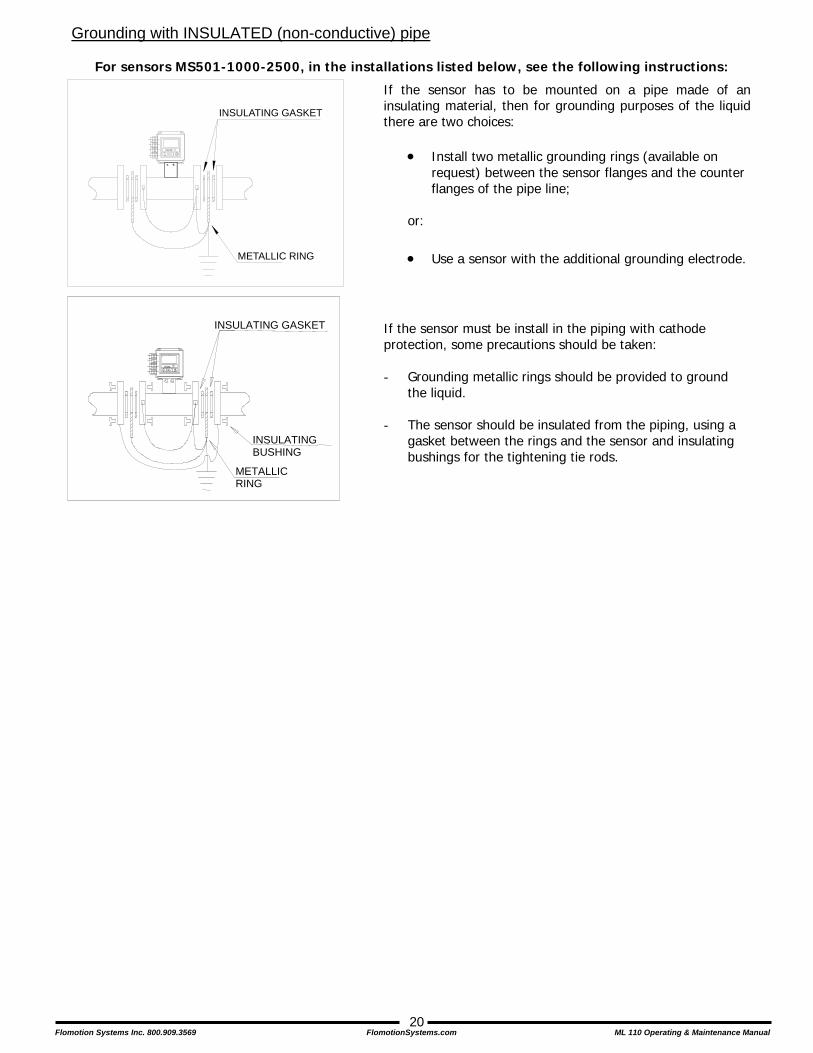
Grounding with INSULATED (non-conductive) pipe
For sensors MS501-1000-2500, in the installations listed below, see the following instructions:
If the sensor must be install in the piping with cathode protection, some precautions should be taken: - Grounding metallic rings should be provided to ground
the liquid.
- The sensor should be insulated from the piping, using a gasket between the rings and the sensor and insulating bushings for the tightening tie rods.
If the sensor has to be mounted on a pipe made of aninsulating material, then for grounding purposes of the liquidthere are two choices:
• Install two metallic grounding rings (available on request) between the sensor flanges and the counter flanges of the pipe line;
or: • Use a sensor with the additional grounding electrode.
ISOIL
METALLIC RING
INSULATING GASKET
ISOIL
METALLIC RING
INSULATING GASKET
INSULATING BUSHING
Flomotion Systems Inc. 800.909.3569 FlomotionSystems.com ML 110 Operating & Maintenance Manual
21
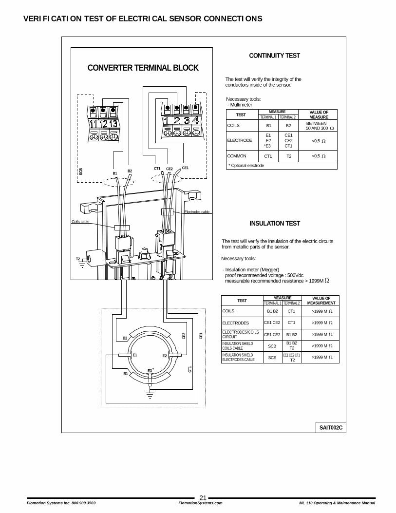
VERIFICATION TEST OF ELECTRICAL SENSOR CONNECTIONS
B1
B2
T2
E1 E2
E3
CE2 CE1CT1B1 B2
∗
* Optional electrode
Coils cable
CONTINUITY TEST
TESTMEASURE VALUE OF
MEASURE
COILS B1 BETWEEN 50 AND 300 Ω
ELECTRODEE1E2 <0,5 Ω
*E3
COMMON CT1 <0,5 Ω
The test will verify the integrity of theconductors inside of the sensor.
INSULATION TEST
TEST MEASURE VALUE OFMEASUREMENT
COILS B1 B2 >1999 M Ω
ELECTRODES CE1 CE2
ELECTRODES/COILSCIRCUIT CE1 CE2
The test will verify the insulation of the electric circuitsfrom metallic parts of the sensor.
>1999 M Ω
>1999 M Ω
SAIT002C
Electrodes cable
CE2
CE1
CT1
INSULATION SHIELDCOILS CABLE SCB >1999 M Ω
INSULATION SHIELDELECTRODES CABLE >1999 M ΩSCE
Necessary tools: - Multimeter
B2
TERMINAL 1 TERMINAL 2
CE1CE2CT1
T2
Necessary tools:
- Insulation meter (Megger) proof recommended voltage : 500Vdc measurable recommended resistance > 1999M Ω
TERMINAL 1 TERMINAL 2
CT1
CT1
B1 B2
B1 B2T2
CE1 CE2 CT1T2
SCB
CONVERTER TERMINAL BLOCK
Flomotion Systems Inc. 800.909.3569 FlomotionSystems.com ML 110 Operating & Maintenance Manual
22
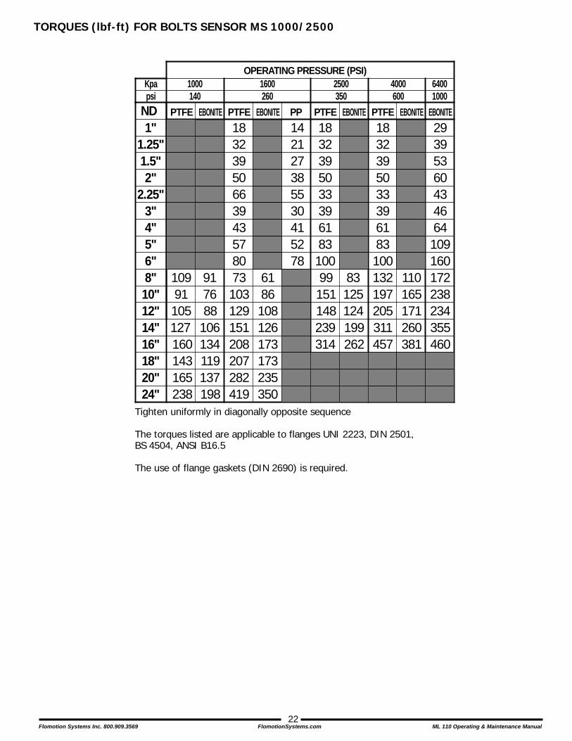
TORQUES (lbf-ft) FOR BOLTS SENSOR MS 1000/2500
Tighten uniformly in diagonally opposite sequence
The torques listed are applicable to flanges UNI 2223, DIN 2501,BS 4504, ANSI B16.5
The use of flange gaskets (DIN 2690) is required.
ND1"
1.5"2"
2.25"3"4"5"6"8"10"12"
1.25"
6186108
83125124
110165171
OPERATING PRESSURE (PSI)Kpa
PTFE EBONITE PTFE EBONITE PP PTFE EBONITE PTFE EBONITE EBONITE
10991105
917688
8073103129
66394357
142127385530415278
99151148
1832395033396183100132197205
172238234
psi1000140
1600260
2500350
4000600
64001000
14"16"18"20"24"
160143165238
127 106134119137198
208207282419
151173173235350
126314239
262199
457311 260
381355460
1832395033396183100
18323950
29395360434664109160
Flomotion Systems Inc. 800.909.3569 FlomotionSystems.com ML 110 Operating & Maintenance Manual
23
SECTION 2 – ML 110 CONVERTER
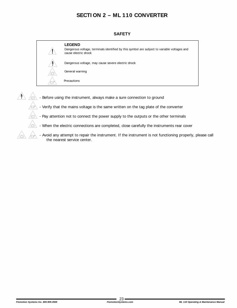
SAFETY
Dangerous voltage, terminals identified by this symbol are subject to variable voltages and cause electric shock
LEGEND
- Before using the instrument, always make a sure connection to ground - Verify that the mains voltage is the same written on the tag plate of the converter - Pay attention not to connect the power supply to the outputs or the other terminals - When the electric connections are completed, close carefully the instruments rear cover
- Avoid any attempt to repair the instrument. If the instrument is not functioning properly, please call
the nearest service center.
Dangerous voltage, may cause severe electric shock
General warning
Precautions

Flomotion Systems Inc. 800.909.3569 FlomotionSystems.com ML 110 Operating & Maintenance Manual
24
OVERALL DIMENSIONS OF CONVERTER ML110
CONVERTER FRONT CONVERTER REAR
127
124
129
168
78
6.6”
4.9”
5.0”
5.1”
COVER POSITIONS
FIXED COVER
120°
PULL IN THE ARROW DIRECTION TO REMOVE THE COVER
3.1”
Flomotion Systems Inc. 800.909.3569 FlomotionSystems.com ML 110 Operating & Maintenance Manual
25
TECHNICAL CHARACTERISTICS
ELECTRICAL CHARACTERISTICS
Classification of the instrument: class I, IP 65, category of installation II
Power supply version
Power supply voltage
Power supply frequency
Pmax current max
HV 90-265 Vac 44-66 Hz 3W/5VA 35 mA
LV 11.5-60 Vdc 15-45 Vac 0-44-66 Hz 3W/5VA 300 mA
Input/output isolation:
• Inputs and outputs are insulated up to 500V • The 4-20 mA output (optional) is electrically connected to the ON/OFF outputs and with the power supply (24VDC) of the
outputs. ENVIRONMENTAL CONDITIONS OF USE
• The instrument can be installed inside or outside of buildings, but protect against direct sunlight exposure. • Altitude: from –200 a 6000 m (from -656 to 19685 feet) • Humidity range: 0-98% • Line voltage range: (see table on technical characteristics)
OPERATING TEMPERATURE OF THE CONVERTER
CONVERTER ML110
Ambient Temperature Min. Max
°C °F °C °F -10* -14* 50 122
* For intermittent use, it is necessary to install a heater.
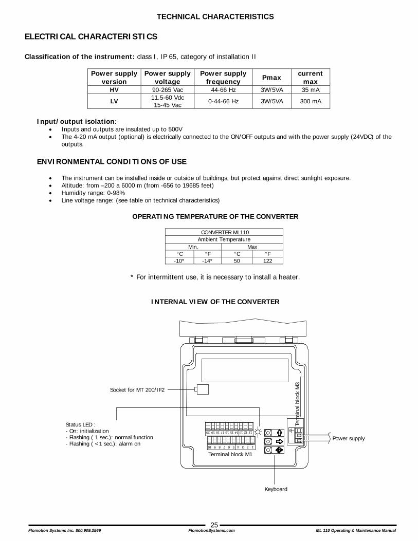
INTERNAL VIEW OF THE CONVERTER
Terminal block M1
Power supply
Socket for MT 200/IF2
Term
inal
blo
ck M
3
Status LED :- On: initialization- Flashing ( 1 sec.): normal function- Flashing ( <1 sec.): alarm on
Keyboard
12345678910
11121314151617181920

Flomotion Systems Inc. 800.909.3569 FlomotionSystems.com ML 110 Operating & Maintenance Manual
26
START UP OF THE INSTRUMENT
GENERAL: BEFORE STARTING UP THE INSTRUMENT PLEASE VERIFY THE FOLLOWING:
• Power supply voltage must correspond to that specified on the name plate • Electric connections must be wired as described in this manual • Ground connections must be properly installed
PARTICULAR INDICATIONS:
When the instrument is powered, if the converter exhibits different operating conditions from the last shutdown, it initiates a verification cycle of the converter while displaying an incrementing diagnostic number from 0 through 90. When the diagnostic is complete an error number will be displayed referencing the chart at the back of this manual. A text message will also be displayed on the alarm screen (to view alarms, from the main display screen press the UP arrow key)
ELECTRICAL CONNECTIONS MS SERIES SENSOR TO CONVERTER
123411
12
13
Electrode 1Electrode 2CommonShieldShieldCoil 1Coil 2
SENSOR SEPARATE VERSION(max length of cable: mt 20) CONVERTER TERMINAL BLOCK M1
Sudden movements of the cable, can causemeasurement noise
C014 CABLE
12345678910
11121314151617181920
WIRING FOR M501 SENSOR TO CONVERTER

Flomotion Systems Inc. 800.909.3569 FlomotionSystems.com ML 110 Operating & Maintenance Manual
27
INPUT/OUTPUT
Terminal block M1 diagram
12345678910
11121314151617181920
-
E C E CE
+
SC B2 B1 SC
OUT2 OUT1 24V24V COILS
E1E2CSC
+-
4-20mA ELECTRODES
• Before connecting the power supply, verify that the main voltage falls between the limits indicated on the nametag.
• Use only approved wiring. • The power supply line must be equipped with an external protection for
current overload (fuse or automatic circuit breaker with limiting capacity not greater than 10 A).
• Place the instrument near a circuit breaker that is easily accessible by the operator and clearly identified.
• NOTE: For information concerning the characteristics of the meter’s power supply, see “technical characteristics” on the following page.
CONVERTER POWER SUPPLY
L(-)
N(+)
Flomotion Systems Inc. 800.909.3569 FlomotionSystems.com ML 110 Operating & Maintenance Manual
28
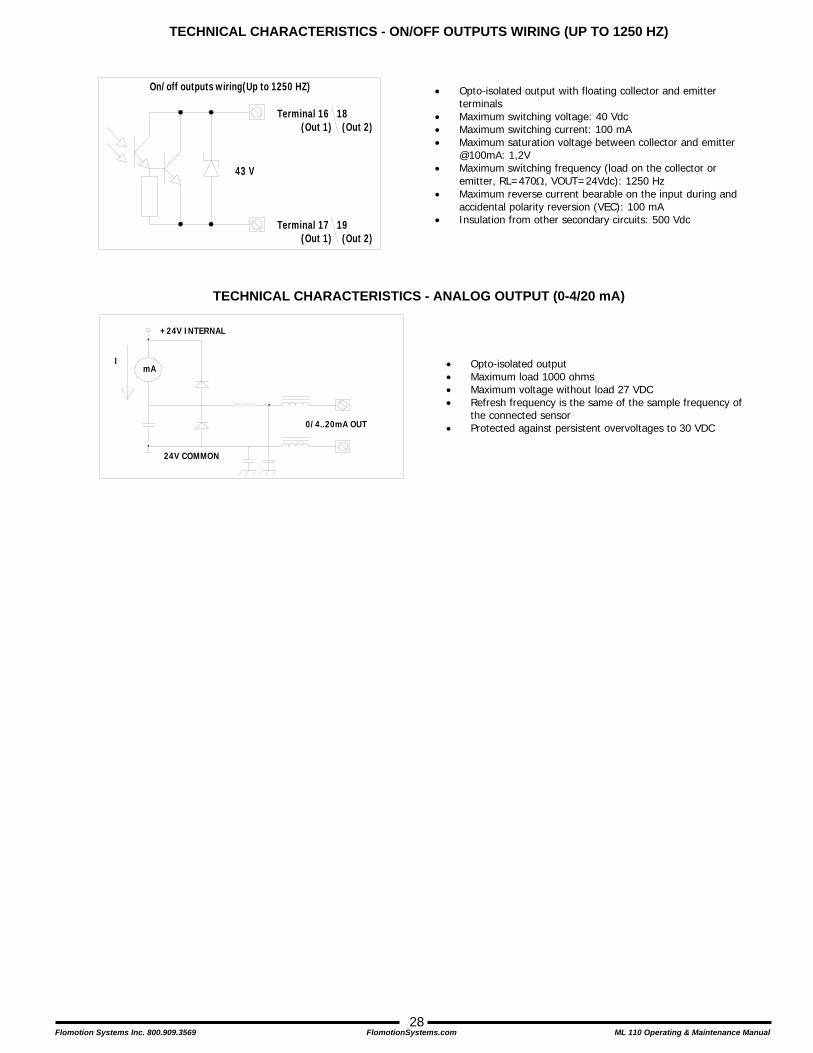
TECHNICAL CHARACTERISTICS - ON/OFF OUTPUTS WIRING (UP TO 1250 HZ)
TECHNICAL CHARACTERISTICS - ANALOG OUTPUT (0-4/20 mA)
• Opto-isolated output with floating collector and emitter terminals
• Maximum switching voltage: 40 Vdc • Maximum switching current: 100 mA • Maximum saturation voltage between collector and emitter
@100mA: 1,2V • Maximum switching frequency (load on the collector or
emitter, RL=470Ω, VOUT=24Vdc): 1250 Hz • Maximum reverse current bearable on the input during and
accidental polarity reversion (VEC): 100 mA • Insulation from other secondary circuits: 500 Vdc
24V COMMON
+24V INTERNAL
0/4..20mA OUT
mAI • Opto-isolated output
• Maximum load 1000 ohms • Maximum voltage without load 27 VDC • Refresh frequency is the same of the sample frequency of
the connected sensor • Protected against persistent overvoltages to 30 VDC
Terminal 16 18(Out 1) (Out 2)
Terminal 17 19(Out 1) (Out 2)
On/off outputs wiring(Up to 1250 HZ)
43 V
Flomotion Systems Inc. 800.909.3569 FlomotionSystems.com ML 110 Operating & Maintenance Manual
29
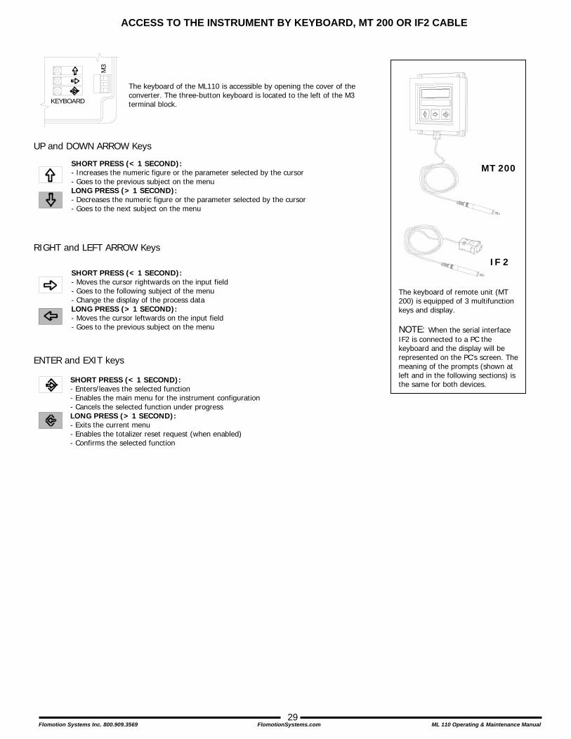
ACCESS TO THE INSTRUMENT BY KEYBOARD, MT 200 OR IF2 CABLE UP and DOWN ARROW Keys RIGHT and LEFT ARROW Keys ENTER and EXIT keys
SHORT PRESS (< 1 SECOND): - Increases the numeric figure or the parameter selected by the cursor - Goes to the previous subject on the menu LONG PRESS (> 1 SECOND): - Decreases the numeric figure or the parameter selected by the cursor - Goes to the next subject on the menu
SHORT PRESS (< 1 SECOND): - Moves the cursor rightwards on the input field - Goes to the following subject of the menu - Change the display of the process data LONG PRESS (> 1 SECOND): - Moves the cursor leftwards on the input field - Goes to the previous subject on the menu
SHORT PRESS (< 1 SECOND): - Enters/leaves the selected function - Enables the main menu for the instrument configuration - Cancels the selected function under progress LONG PRESS (> 1 SECOND): - Exits the current menu - Enables the totalizer reset request (when enabled) - Confirms the selected function
MT 200
IF 2
The keyboard of remote unit (MT 200) is equipped of 3 multifunction keys and display. NOTE: When the serial interface IF2 is connected to a PC the keyboard and the display will be represented on the PC’s screen. The meaning of the prompts (shown at left and in the following sections) is the same for both devices.
KEYBOARDM
3
The keyboard of the ML110 is accessible by opening the cover of the converter. The three-button keyboard is located to the left of the M3 terminal block.
Flomotion Systems Inc. 800.909.3569 FlomotionSystems.com ML 110 Operating & Maintenance Manual
30
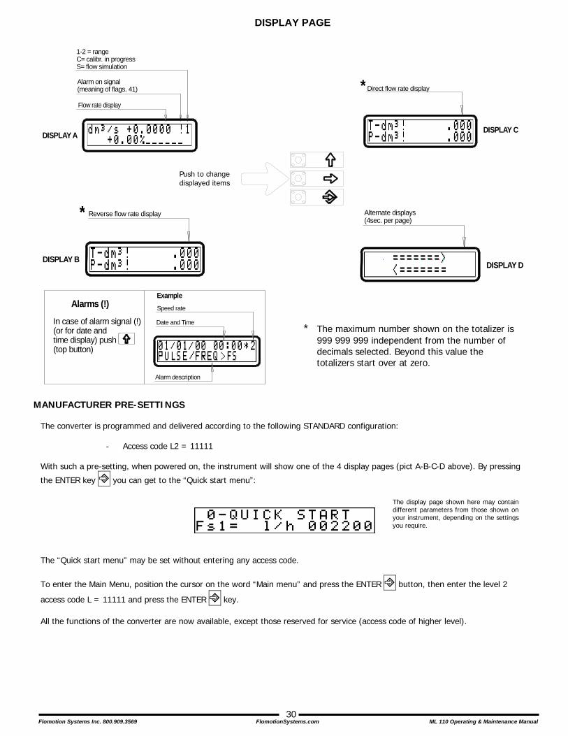
DISPLAY PAGE
MANUFACTURER PRE-SETTINGS
The converter is programmed and delivered according to the following STANDARD configuration: - Access code L2 = 11111
With such a pre-setting, when powered on, the instrument will show one of the 4 display pages (pict A-B-C-D above). By pressing
the ENTER key ! you can get to the “Quick start menu”:
The “Quick start menu” may be set without entering any access code.
To enter the Main Menu, position the cursor on the word “Main menu” and press the ENTER ! button, then enter the level 2
access code L = 11111 and press the ENTER ! key. All the functions of the converter are now available, except those reserved for service (access code of higher level).
The display page shown here may contain different parameters from those shown on your instrument, depending on the settings you require.
Push to change displayed items
1-2 = rangeC= calibr. in progressS= flow simulation
Alarm on signal(meaning of flags. 41)
Flow rate display
DISPLAY A
Direct flow rate display
DISPLAY C
*
Date and Time
Speed rate
Alarm description
Alarms (!)
In case of alarm signal (!)(or for date and time display) push(top button)
Example
Reverse flow rate display
DISPLAY B
* Alternate displays(4sec. per page)
DISPLAY D
* The maximum number shown on the totalizer is 999 999 999 independent from the number of decimals selected. Beyond this value the totalizers start over at zero.

Flomotion Systems Inc. 800.909.3569 FlomotionSystems.com ML 110 Operating & Maintenance Manual
31
ACCESS CODES The information in this manual is related to all the functions available with L2 security level. All the functions available through access codes of higher level are protected and reserved for service personnel only. Access code description: L2 A) with code L2 = 11111 (with this code only) you can access the “Quick start menu”. B) with code L2 = 22222 (with this code only) you disable requests for code L2 and you can proceed with programming without
entering any access code (up to L2 security level). C) With L2 customised (chosen by the user*) you can program all the functions up to L2 security level. You must enter this code
whenever you enter the Main menu. *ATTENTION: take careful note of the custom code you have chosen, there is no way for a user to retrieve it if it is forgotten.
ACCESS CONFIGURATION MENU
From any display page push this key: To choose a menu item push: To enter a menu item:
EXAMPLES
EX. 1 Set full scale from QUICK START menu
Ex. 2 Set full scale from main menu
FROM DISPLAY PAGES
PUSH ENTER: !
FS1= Gal/m 0012.5
!
choose the volume unit with the key:
! in³, GAL, Gal, ft³, Bbl, yd³...
"
choose the type of unit with the key:
! • Metric volume units • British or American volume units • Metric mass units • British or American mass units
"
choose the time unit of measure with the ! key:
s, m, h, d,
Set the numeric value
with the " key:
Use the " key: to move to the numeric side
"
FROM DISPLAY PAGES
PUSH ENTER: !
KEYCODE: 00000
" !
FS1= Gal/m 0012.5
!
choose the volume unit with the key:
! in³, GAL, Gal, ft³, Bbl, yd³...
"
choose the type of unit with the key:
! • Metric volume units • British or American volume units • Metric mass units • British or American mass units
choose the time unit of measure
with the ! key: s, m, h, d,
Set the numeric value
with the " key:
Use the " key: to move to the numeric side
"

Flomotion Systems Inc. 800.909.3569 FlomotionSystems.com ML 110 Operating & Maintenance Manual
32
PROGRAM FUNCTION FLOW CHART 1. Sensor
2. Scale
3. Measure
4. Alarm
6. Output
8. Display
10. Diagnostic
11 Internal Data
Set Nominal Diameter
Set KA
Set KL
Empty Pipe Detect Enable/Disable Empty Pipe Test
Start AZ Cal.
Start EP Cal.
Full Scale 1 Value Set VolumeUnit
Type ofUnit
Time Unit ofMeasure
NumericValueFull Scale 2 Value Set
Unit of Measure Type of Unit # of Totalizer Decimals
CH1 Pulse Value Unit ofMeasureCH2 Pulse Value
CH1 Pulse Duration
CH2 Pulse Duration
CH1 Full Scale Frequency
CH2 Full Scale Frequency
Time Constant Set
Acceleration Threshold Set
Type ofUnit Value
Nominal Signal Peak Cutoff Threshold Set
Low Flow Zero Threshold Set
Enable 50/60 Hz Filter
Enable/Disable
Enable/Disable
Enable/Disable Energy Saving Function
MAX Flow Rate Value
MIN Flow Rate Value
Hysteresis Threshold
Empty Pipe Detection Threshold
4-20 mA Current Alarm Set
4.1 MAX THR
4.2 MIN THR
4.3 HYST
4.4 E. P. THR
4.5 mA VAL. FAULT
3.1 TCONST
3.2 SKIP THR
3.3 PEAK THR
3.4 CUT-OFF
3.5 FILTER
3.6 AUTOCAL
3.7 AUTORANGE
3.8 E. SAVING
2.1 FS1
2.2 FS2
2.3 Tot.MU
2.4 IMP1
2.5 IMP2
2.6 TPUL1
2.7 TPUL2
2.8 FRQ1
2.9 FRQ2
1.1 ND
1.2 KA
1.3 KL
1.4 E.P. Detect
1.5 AutoZero Cal.
1.6 E.P. Calibr.
Frequency Output Alarm Set4.6 Hz VAL. FAULT
See Output MenuDescription
Choose Current Value Output 1
6.1 OUT 1
6.2 OUT 2
6.3 DUTY CYCLE
6.4 OUT. MA1 Start/End Scale (4-20mA) and Sign (+/-)
E. English / I. Italian / F. French
Display Refresh
LCD Contrast
Reset Total Direct Flow Totalizer
Reset Partial Direct Flow Totalizer
8.1 LANGUAGE
8.2 D. RATE
8.3 CONTRAST
8.4 T+ RESET
8.5 P+ RESET
Reset Total Reverse Flow Totalizer8.6 T- RESET
Reset Partial Reverse Flow Totalizer8.7 P- RESET
Enable Calibration
Begin Meter Autotest Function
Enable Flow Rate Simulation (set value from main display)
10.1 CALIBRATION
10.2 SELF TEST
10.3 SIMULATION
Enter Level 2 Access Code
Recall Factory Default Presets
Load User Saved Settings
11.1 L2 KEYCODE
11.2 LOAD FACTORY
11.3 LOAD USER
Save User Settings
Set KS Value
11.4 SAVE USER
11.5 KS
Service Diagnostics:10.4 Electrodes Test
10.5 Display Data10.6 Zero
Service Diagnostics11.6 - Memory Reset11.7 - Serial Number11.8 - Hours11.9 - KT11.10 - KR11.11 - KS
11.12 - Zero11.13 - DAC1 20mA11.14 - DAC1 4mA11.15 - Data Logger11.16 - Input11.17 - DAC111.18 - RS485
Note: Some functions are only displayed if you
have enabled other functions or with the insertion
of additional modules.
Flomotion Systems Inc. 800.909.3569 FlomotionSystems.com ML 110 Operating & Maintenance Manual
33
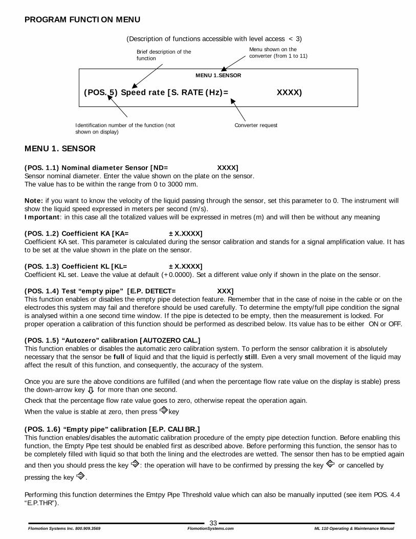
PROGRAM FUNCTION MENU
(Description of functions accessible with level access < 3)
MENU 1. SENSOR (POS. 1.1) Nominal diameter Sensor [ND= XXXX] Sensor nominal diameter. Enter the value shown on the plate on the sensor. The value has to be within the range from 0 to 3000 mm. Note: if you want to know the velocity of the liquid passing through the sensor, set this parameter to 0. The instrument will show the liquid speed expressed in meters per second (m/s). Important: in this case all the totalized values will be expressed in metres (m) and will then be without any meaning (POS. 1.2) Coefficient KA [KA= ±X.XXXX] Coefficient KA set. This parameter is calculated during the sensor calibration and stands for a signal amplification value. It has to be set at the value shown in the plate on the sensor. (POS. 1.3) Coefficient KL [KL= ±X.XXXX] Coefficient KL set. Leave the value at default (+0.0000). Set a different value only if shown in the plate on the sensor. (POS. 1.4) Test “empty pipe” [E.P. DETECT= XXX] This function enables or disables the empty pipe detection feature. Remember that in the case of noise in the cable or on the electrodes this system may fail and therefore should be used carefully. To determine the empty/full pipe condition the signal is analysed within a one second time window. If the pipe is detected to be empty, then the measurement is locked. For proper operation a calibration of this function should be performed as described below. Its value has to be either ON or OFF. (POS. 1.5) “Autozero” calibration [AUTOZERO CAL.] This function enables or disables the automatic zero calibration system. To perform the sensor calibration it is absolutely necessary that the sensor be full of liquid and that the liquid is perfectly still. Even a very small movement of the liquid may affect the result of this function, and consequently, the accuracy of the system. Once you are sure the above conditions are fulfilled (and when the percentage flow rate value on the display is stable) press the down-arrow key # for more than one second.
Check that the percentage flow rate value goes to zero, otherwise repeat the operation again.
When the value is stable at zero, then press !key (POS. 1.6) “Empty pipe” calibration [E.P. CALIBR.] This function enables/disables the automatic calibration procedure of the empty pipe detection function. Before enabling this function, the Empty Pipe test should be enabled first as described above. Before performing this function, the sensor has to be completely filled with liquid so that both the lining and the electrodes are wetted. The sensor then has to be emptied again
and then you should press the key !: the operation will have to be confirmed by pressing the key " or cancelled by
pressing the key !. Performing this function determines the Emtpy Pipe Threshold value which can also be manually inputted (see item POS. 4.4 “E.P.THR”).
MENU 1.SENSOR
(POS. 5) Speed rate [S. RATE (Hz)= XXXX)
Menu shown on the converter (from 1 to 11)
Brief description of the function
Identification number of the function (not shown on display)
Converter request

Flomotion Systems Inc. 800.909.3569 FlomotionSystems.com ML 110 Operating & Maintenance Manual
34
MENU 2. SCALES (POS. 2.1) Full scale no. 1 [FS1=dm³/S X.XXXX] Full-scale value set for range No. 1. There are four fields needed in order to set this parameter, from left to right: 1) volume unit of measure, 2) type of unit, 3) time unit of measure and 4) numeric value. The selection is made by positioning the cursor on the field to modify. To change the type of unit of measure (metric, British or American, mass or volume) the cursor has to be positioned on the “/” (slash) symbol (field No. 2). When the nominal diameter is set to zero it is only possible to modify the numeric field, since the unit of measure stays at m/sec. The following tables show the units of measure available and the conversion factor by comparison with 1 dm3 and 1 kg. The converter accepts any kind of combination of units of measure satisfying both the following conditions: • Numeric field value ≤ 9999
• 1/25 fsmax ≤ numeric field value ≤ fsmax. where fsmax is the maximum full scale value corresponding to the sensor, equal to a 10 m/sec liquid speed.
The units of measure are shown as they appear on the display. Note that the British and American units are designated by using capital and small characters.
Metric units of measure cm3 0.001 Cubic centimetre ml 0.001 Millilitre l 1.000 Litre
dm3 1.000 Cubic decimetre dal 10.000 Decalitre hl 100.000 Hectolitre m3 1000.000 Cubic metre
British or American volume unit of measure
in3 0.0163871 Cubic inch GAL 4.545771 British gallon Gal 3.785333 American gallon ft3 28.31685 Cubic foot Bbl 119.238 Standard barrel BBL 158.984 Oil barrel yd3 764.555 Cubic yard
Metric mass units of measure
G 0.001 Gram Kg 1.000 Kilogram T 1000.000 Ton
British and American mass units of measure
Oz 0.028350 Ounce Lb 0.453591 Pound
Ton 907.18 short tons When a mass unit of measure is set, the specific gravity function is automatically enabled by the system. Please, note that temperature affects the mass measurement significantly and therefore with certain liquids this may cause considerable measurement errors. The units of measure of time may be chosen among the following values: s = second, m = minute, h = hour, d = day. (POS. 2.2) Full scale n. 2 [FS2=dm³/s X.XXXX] Full scale set for scale N.2. Please, refer to the previous function as far as its description is concerned. This function is identical to the previous one (POS. 2.1 Full scale n. 1) and is enabled by the system only when the relevant input or output functions are enabled as well (See item POS. 3.7 AUTORANGE.)

Flomotion Systems Inc. 800.909.3569 FlomotionSystems.com ML 110 Operating & Maintenance Manual
35
(POS. 2.3) Unit of measure and number of decimal totalizers [UM.tot:dm³ X.XXX] Setting the unit of measure and number of decimals for the totalizer display. To set the unit of measure, position the cursor on field of the actual unit of measure; To set the type of unit, position the cursor on the blank space between the unit of measure and the numeric value; To set the number of decimals shown on the totalizers position the cursor on the numeric field and choose one of the possible combinations: 1000-01.00-001.0-00001.
(POS. 2.4) Pulse value channel 1 and unit of measure of the totalizers [IMP1=dm³ X.XXXXX] Setting of the volume corresponding to each pulse of channel 1 and totalizer unit of measure. There are three fields to fill in to set this parameter, from left to right: 1) unit of measure, 2) type of unit of measure and 3) numeric value. The selection is performed by positioning the cursor on the field to modify. To change the type of unit of measure (metric, British or American, mass or volume) just position the cursor on the blank space between the unit of measure and the numeric value. When the nominal diameter is set to zero, it is only possible to modify the numeric field since the unit of measure stays at meters (m). The possible units of measure are those described above in POS. 2.1. This function is active only if the pulse output on channel 1 has been enabled (see item POS. 6.1 OUT1).
(POS. 2.5) Pulse value channel 2 and unit of measure of the totalizers [IMP=dm³ X.XXXXX] Setting the volume corresponding to each pulse of channel 2 and totalizers unit of measure. This function is identical to the previous one and is active only if the pulse emission on channel 1 has been set as enabled (see Function POS. 6.2). (POS. 2.6) Pulse duration channel 1 [TPUL1=ms XXXX.XX] Setting the duration of the pulse generated on channel 1. Its value is expressed in milliseconds and has to be between 0.4 and 9999.99. When the optional high frequency output option is present, then the minimum value can go down to 0.04 milliseconds. ATTENTION: since the instrument cannot detect which type of device it is connected to, it is up to the user to verify the set pulse duration is compatible with the external device processing such pulses. If, for example, an electro-mechanical pulse counter is connected, then two kind of problems may occur: if the pulse is too long than the totalizer coils may overheat or, if it too short, the counter may not count, even damaging the converter output. This function is only active when the pulse output function on channel 1 is enabled.
(POS. 2.7) Pulse duration channel 2 [TPUL2=ms XXXX.XX] Setting of the duration of the pulse generated on channel 2. Its value is expressed in milliseconds and has to be between 0.4 and 9999.99. When the optional high frequency output is present, then the minimum value can go down to 0.04 milliseconds. ATTENTION: use care in selecting the pulse duration as mentioned above. This function is only active when the pulse emission function on channel 2 is enabled.
(POS. 2.8) Full scale frequency channel 1 [FRQ1=Hz XXXXX.X] Full-scale frequency set for channel 1. Its value is expressed in Hertz and is between 1.0 and 1000.0. When the high frequency output is present the maximum value may go up to 10000.0. ATTENTION: use care in selecting the frequency as mentioned above. This function is only enabled when the frequency generation mode on channel 1 is active. (POS. 2.9) Full scale frequency channel 2 [FRQ2=Hz XXXXX.X] Full-scale frequency set for channel 2. Its value is expressed in Hertz and is between 1.0 and 1000.0. ATTENTION: use care in selecting the frequency as mentioned above. This function is only enabled when the frequency generation mode on channel 2 is active.

Flomotion Systems Inc. 800.909.3569 FlomotionSystems.com ML 110 Operating & Maintenance Manual
36
MENU 3. MEASURE
(POS. 3.1) Time constant [TCONST=s XXXX.X] Time constant set. This parameter affects the integrating filter making the instrument response quicker or slower, according to the set value. A higher value corresponds to a more stable but slower response, a smaller value the opposite. The most common values are from 1 to 5 seconds. The value of this parameter has to be within the range from 0 (integral filter disabled) to 6000.0 seconds. The following diagram shows the response of the instrument for a flow rate variation from 0 to 100% within the T time constant period:
T 3T 4T 5T2T0t
%100
69899699
100
0
0
FLOW RATE
MEASURE
%
(POS. 3.2) Acceleration threshold [SKIP THR=% XXX] Acceleration threshold set. The acceleration threshold stands for the limit beyond which a flow rate variation determines an immediate response at the output, without being filtered by the time constant. This system allows the instrument to have an immediate response in case of big variations of the flow rate, filtering (and delaying) the response to small variations. This results in a very stable measurement, ready to follow the process. The value is set as a percentage of the full-scale value from 0 to 125%. If such a value is set to zero any flow rate variation bigger than 0.5% of the full-scale value will immediately affect the outputs. The following diagram shows the instrument response in two cases: a flow rate variation from 0 to 10% completely absorbed by the time constant effect and a variation from 10% to 100% exceeding the acceleration threshold and then immediately sent to the output. In actual fact there is always a minimum time between the measure acquisition and the output update.
0t
%
100
100
0
0
FLOW RATE
MEASURE
%
10
10
5T

Flomotion Systems Inc. 800.909.3569 FlomotionSystems.com ML 110 Operating & Maintenance Manual
37
(POS. 3.3) Peak cut off threshold [PEAK THR=% XXX] Anomalous signal pick cut off threshold set. This parameter allows you to set the maximum value of deviation of the actual measure sample by comparison with the average one. If the new value is higher than the set limit, than such a value is “cut” to the limit value. This function is used to make the meter less sensitive to big perturbations on the flow rate measure, as may happen when there are solids in suspension in the liquid hitting against the electrodes causing high electrical noise. The permitted values of this function go from 0 to 125 % and are referred to the full-scale value. If this parameter is set to zero the peak detection function is disabled and any new measurement will be accepted and processed as-is by the converter. (POS. 3.4) Low flow zero threshold [CUT-OFF=% XX.X] Low flow zero threshold set. When the flow rate value falls below this parameter the flow rate is assumed to be zero and is set to such a value by the converter. This parameter can be set from 0 to 25.0% of the full-scale value. When this parameter is set to zero this function is disabled. (POS. 3.5) Set filter 50/60Hz [FILTER=S 1/0.2] Filter on the power supply frequency. This value can be set to 0.2 s ("fast" measure) or to 1 s (greater filter effect of noise in the liquid). (POS. 3.6) Auto-calibration [AUTOCAL= ON/OFF] Enables or disables the auto-calibration function. When enabled the converter performs a calibration cycle once every hour. During such a cycle the measurement is “frozen” at the latest measured value. The calibration lasts from 8 to 15 seconds and completely removes the thermal derivation error effects on the measurement. It is recommended to enable this function if the instrument undergoes strong temperature variations during operation. (POS. 3.7) Automatic scale change enable [AUTORANGE= ON/OFF] Enables/disables the automatic change of scale. The meter has two different working ranges to handle variable process conditions. In order to get the best results it is important that range No. 2 is bigger than No. 1. When the flow rate increases and reaches 100% of full scale 1, then the meter automatically switches to scale No. 2. When the flow rate decreases again reaching a value on scale 2 equal to 90% of full scale No. 1, then the active scale is No. 1 again. Allowed values for this parameter: ON / OFF.
(POS. 3.8) Energy saving enable [E.SAVING= ON/OFF] Automatic energy saving function enable. This function is used when the instrument is powered by a battery or solar cells, which provide energy savings of up to 60-80%. The energy consumption is controlled by the ratio between the measuring cycles powering the coils and the cycles without powering the coils. When the flow rate is stable the number of “off” cycles is higher than the “on” ones, so that the average consumption is significantly reduced. If the flow rate suddenly changes, then the meter switches to a higher number of measuring cycles (in order to get a higher response time), then switching off the cycles as soon as the flow rate becomes stable again. If the flow rate varies below the “acceleration threshold” percentage value, then the meter continues with “off” cycles, but as soon as the flow rate value exceeds such a threshold, the meter switches back to a higher number of measuring cycles again. The speed that the meter switches the excitation cycles on and off is different: from a constant flow rate to a variable one it is a very fast process, while from variable flow rate to a stable one such a process is much slower. Allowed values for this parameter: ON/OFF. NOTE: to optimize this function it is recommended that you choose a value for the acceleration threshold within 10-15%

Flomotion Systems Inc. 800.909.3569 FlomotionSystems.com ML 110 Operating & Maintenance Manual
38
MENU 4. ALARMS (POS. 4.1) Maximum flow rate threshold [MAX THR=% XXX] Maximum flow rate value alarm set. When the flow rate value exceeds such a threshold as absolute magnitude (i.e. not considering the sign), then an alarm message is generated. The value of this parameter is expressed as a percentage of the full-scale value and may be set from 0 to 125%. Setting this parameter to zero will disable the alarm generation. (POS. 4.2) Minimum flow rate threshold [MIN THR=% XXX] Minimum flow rate value alarm set. When the flow rate value falls below such a threshold as absolute magnitude (i.e. not considering the sign), then an alarm message is generated. The value of this parameter is expressed as percentage of the full-scale value and may be set from 0 to 125%. Setting this parameter to zero will disable the alarm generation. (POS. 4.3) Hysteresis [HYST=% XX] Hysteresis threshold set for the minimum and maximum flow rate alarms. (POS. 4.4) “Empty pipe” detection threshold [E.P.THR= XXX] Empty pipe detection threshold set. The value of this parameter is automatically set by the function “Empty pipe calibration” within the menu SENSOR. (POS. 4.5) Current output value in case of failure [mA VAL.FAULT =% XXX] Setting of the value the 0/4-20 mA current output in the case of one of the following failures:
• Empty pipe • Coils interrupted • ADC error
The allowed range is from 0 to 120% of the 0-20 mA scale, 120% corresponds to 24 mA and does not depend on the selected range (0-20 / 4-20 mA). The NAMUR NE43 recommendations suggest an alarm signalling value for the current output lower than 3.6 mA (<18%) or bigger than 21 mA (>105%). It would then be preferable to set the value of this function at the 10%, so that the current value in case of the failures shown above would be 2 mA, allowing the following diagnostics:
• Current < 2 mA - 5%: line interrupted, power supply failure or faulty converter; • 2 mA -5% ≤ current ≤ 2 mA + 5%: hardware alarm; • 4 mA ≤ current ≤ 20 mA: normal working range; • 20 mA < current ≤ 22 mA: out of range, measure above 100% f.s.
(POS. 4.6) Frequency output value in case of failure [Hz VAL.FAULT=% XXX] Setting of the value the frequency output has to be in the case of one of the following failures:
• Empty pipe • Coils interrupted • ADC error
The allowed range is from 0 to 125% of the frequency full-scale value. Although there are no specific rules regulating cases like this one, it would be convenient to use the failure information as follows:
• 0% Hz ≤ frequency ≤ 100% f.s.: normal working range; • 100% f.s. < frequency ≤ 110% f.s.: overflow, measure above the 100% of the f.s.; • 115% f.s. ≤ frequency ≤ 125% f.s.: hardware alarm condition.
This function is active only when one of the outputs is set as frequency.

Flomotion Systems Inc. 800.909.3569 FlomotionSystems.com ML 110 Operating & Maintenance Manual
39
MENU 6. OUTPUT (POS. 6.1) Choice of the function corresponding to on/off output 1 [OUT1= XXXXXX] Choice of the function corresponding to digital Output 1. The functions are listed in the table below. (POS. 6.2) Choice of the function corresponding to on/off output 2 [OUT2= XXXXXX] Choice of the function corresponding to digital Output 2. The functions are listed in the table below. Attention: Output 2 is optional and is mounted on an optional add on module.
(POS. 6.3) duty cycle value for output pulses/frequency [OUT.1= XXXXXX]
The duty cycle function defines the time ratio between ON and OFF state when frequency output are used: 50% it mean that the ON phase will be the same of OFF phase, 60% it mean that the phase ON will be 60 % and phase OFF will be 40% of the total cycle time. When pulses output are used, the duty cycle define the OFF phase because the ON phase it’s already set with the function "PULSE DURATION"(see menu “SCALE”). In this case if is setting for example the duty cycle at 50% and the pulse duration to 50ms, the OFF phase will be the same of ON phase. The formula for calculate the minimum time of the OFF phase and the time of total cycle is the following:
- T. total cycle= 100 x (pulse duration in ms)/ (duty cycle) - T. OFF phase = T. total cycle - pulse duration
Note: If the value of the function is set to 0 the issue of the pulses happens in synchronous mode with the flow rate therefore when is uses the function in frequency DOESN'T set the duty cycle to 0. The function is active only if one output is on pulse and/or frequency
(POS. 6.4) Function and the range of current output n.2 [OUT.mA2=X÷XX ±] (OPTIONAL) Choice of the function and the range of current output N.1. The current output N.1 is optional and it is mounted on the main board. There are three fields to modify for this function: • Scale zero: 4 or 0 mA • Full scale: 20 or 22 mA • Field: + = positive, - = negative, ± = both, -0+ = central zero scale The values corresponding to the scale points are shown in the following chart:
FUNCTION FOR OUTPUT 1, 2. OFF: DISABLED #1PULS+: PULSE ON CHANNEL 1 FOR POSITIVE FLOW RATE #1PULS-: PULSE ON CHANNEL 1 FOR NEGATIVE FLOW RATE #1PULS±: PULSE ON CHANNEL 1 FOR POSITIVE AND NEGATIVE FLOW RATE #2PULS+: PULSE ON CHANNEL 2 FOR POSITIVE FLOW RATE #2PULS-: PULSE ON CHANNEL 2 FOR NEGATIVE FLOW RATE #2PULS±: PULSE ON CHANNEL 2 FOR POSITIVE AND NEGATIVE FLOW RATE #1FREQ+: FREQUENCY CHANNEL 1 FOR POSITIVE FLOW RATE #1FREQ-: FREQUENCY CHANNEL 1 FOR NEGATIVE FLOW RATE #1FREQ±: FREQUENCY CHANNEL 1 FOR POSITIVE AND NEGATIVE FLOW RATE #2FREQ+: FREQUENCY CHANNEL 2 FOR POSITIVE FLOW RATE #2FREQ-: FREQUENCY CHANNEL 2 FOR NEGATIVE FLOW RATE #2FREQ±: FREQUENCY CHANNEL 2 FOR POSITIVE AND NEGATIVE FLOW RATE SIGN: FLOW DIRECTION OUTPUT (ENERGISED = -) RANGE: RANGE INDICATION OUTPUT (ENERGISED = SCALE 2) MAX AL: MAX FLOW RATE OUTPUT(ENERGISED = AL. OFF) MIN AL: MIN FLOW RATE OUTPUT(ENERGISED = AL. OFF) MAX+MIN: MAX AND MIN FLOW RATE ALARM OUTPUT (ENERGISED = AL. OFF) EMPTY PIPE: EMPTY PIPE ALARM OUTPUT (ENERGISED = FULL PIPE) OVERFLOW.: OUT OF RANGE ALARM OUTPUT (ENERGISED = FLOW RATE OK) HW ALARM: CUMULATIVE ALARM OUTPUT interrupt coils, empty pipe, measure error (ENERGISED = NO ALARMS)
Flomotion Systems Inc. 800.909.3569 FlomotionSystems.com ML 110 Operating & Maintenance Manual
40
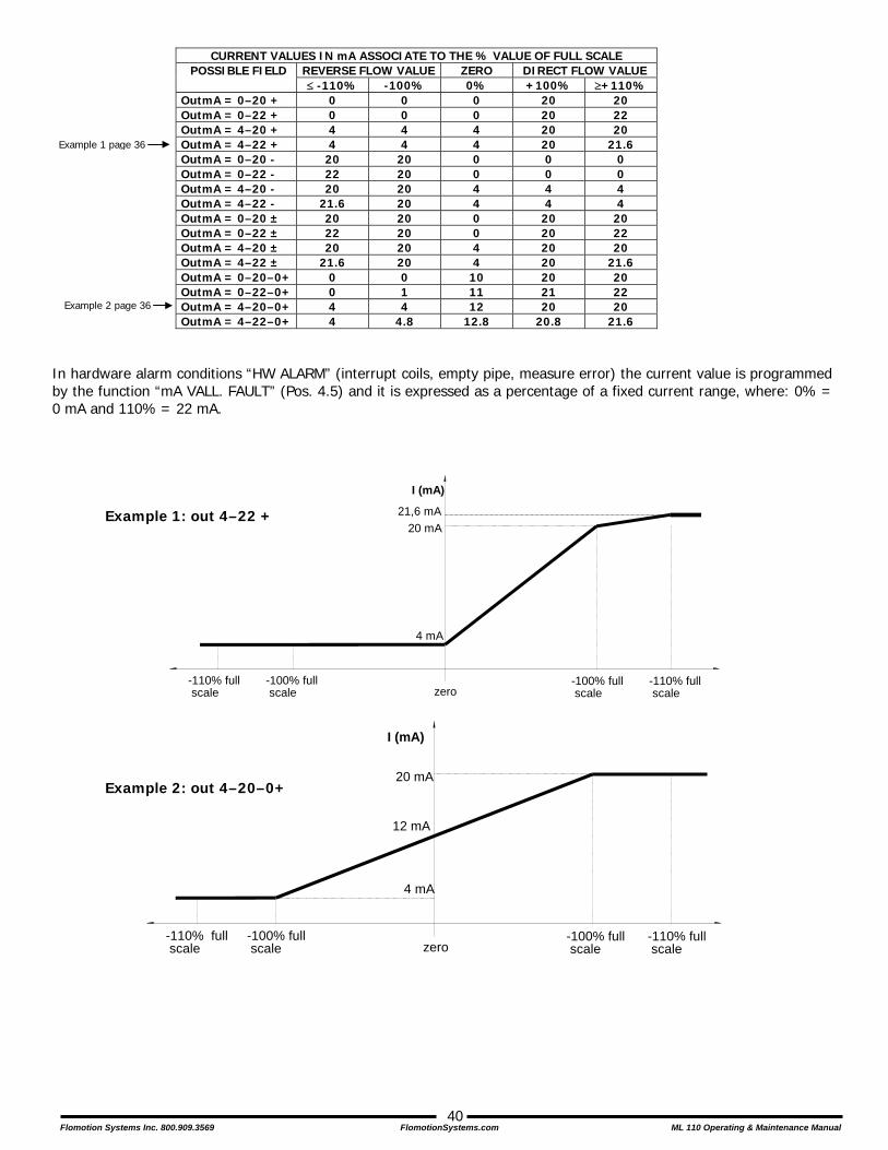
CURRENT VALUES IN mA ASSOCIATE TO THE % VALUE OF FULL SCALE
REVERSE FLOW VALUE ZERO DIRECT FLOW VALUE POSSIBLE FIELD ≤ -110% -100% 0% +100% ≥+110%
OutmA = 0–20 + 0 0 0 20 20 OutmA = 0–22 + 0 0 0 20 22 OutmA = 4–20 + 4 4 4 20 20 OutmA = 4–22 + 4 4 4 20 21.6 OutmA = 0–20 - 20 20 0 0 0 OutmA = 0–22 - 22 20 0 0 0 OutmA = 4–20 - 20 20 4 4 4 OutmA = 4–22 - 21.6 20 4 4 4 OutmA = 0–20 ± 20 20 0 20 20 OutmA = 0–22 ± 22 20 0 20 22 OutmA = 4–20 ± 20 20 4 20 20 OutmA = 4–22 ± 21.6 20 4 20 21.6 OutmA = 0–20–0+ 0 0 10 20 20 OutmA = 0–22–0+ 0 1 11 21 22 OutmA = 4–20–0+ 4 4 12 20 20 OutmA = 4–22–0+ 4 4.8 12.8 20.8 21.6
In hardware alarm conditions “HW ALARM” (interrupt coils, empty pipe, measure error) the current value is programmed by the function “mA VALL. FAULT” (Pos. 4.5) and it is expressed as a percentage of a fixed current range, where: 0% = 0 mA and 110% = 22 mA.
Example 1 page 36
Example 2 page 36
Example 1: out 4–22 +
Example 2: out 4–20–0+
I (mA)
-100% full scale zero
-110% full scale
4 mA
-110% full scale
-100% full scale
20 mA
12 mA
I (mA)
-100% full scale zero
-110% full scale
4 mA
-110% full scale
-100% full scale
20 mA21,6 mA
Flomotion Systems Inc. 800.909.3569 FlomotionSystems.com ML 110 Operating & Maintenance Manual
41
MENU 8. DISPLAY
(POS. 8.1) Language [LANGUAGE= XX] Choice of the programming language. There are 4 languages available: E = English, I = Italian, F = French, S = Spanish. (POS. 8.2) Display refresh frequency set [D.RATE=Hz X] Set the frequency the data on the display are refreshed at. This parameter affects only the display layout and not the response time of the meter itself. The possible choices are: 0.1 – 0.2 – 0.5 – 1, 2, 5 or 10 Hz.
(POS. 8.3) Display contrast set [CONTRAST= X] Display visual contrast set. The contrast can change in relation to ambient temperature. The set values are from 0 to 15. This function is updated only when leaving the function itself. Contrast also set can be change from the main display pages by pushing the # key for 8 seconds or more. In this way the contrast set menu will be visualized at the release of the key.
(POS. 8.4) Total Totalizer + reset activation [T+ RESET ] Activates the reset of the total direct flow totalizer
(POS. 8.5) Partial + totalizer reset enable [P+ RESET] Activates the reset of the partial direct flow totalizer
(POS. 8.6) Total – totalizer reset enable [T- RESET ] Activates the reset of the total reverse (negative) flow totalizer (POS. 8.7) Partial – totalizer reset enable [P - RESET] Activates the reset of the partial reverse (negative) flow totalizer The activation of the functions 8.4-8.5-8.6-8.7 happens pressing the ! key during the display of the function. To the request " EXECUTE?" press for more than two second the ! key to proceed. Press any other key to delete the operation. Note: It is possible to reset the partial totalizers even in the following mode:
• From the main display press the ! key for more than 2 sec.
• Set the L2 code and press the ! key. The following question will be shown: "EXECUTE?". Press the ! key for more than 2 sec. to proceed. Press any other key to cancel the operation.
Flomotion Systems Inc. 800.909.3569 FlomotionSystems.com ML 110 Operating & Maintenance Manual
42
MENU 10. DIAGNOSTIC
(POS. 10.1) Meter “calibration” [CALIBRATION] Enable the calibration of the meter. The activation of this function happens by pressing the ! key during the display (POS. 10.2) “Autotest” function enable [SELF TEST] Meter auto-test function. This function stops the normal functioning of the meter and performs a complete test cycle on the measurement input circuits and on the excitation generator. To activate this function, after selecting it, push the ! key, at the question: “EXECUTE?” push the ! key for more than 1 second to start the auto test, or any other key to delete the operation. The result of the test is shown on the display. At the end of the operation error messages will be displayed (explained in Appendix A.) or you will return to the main display screen. This function is also automatically performed when switching the device on. (POS. 10.3) Flow rate simulation enable [SIMULATION] Flow rate simulation enable. With this function it is possible to enable the generation of an internal signal, which is applied to the input terminals simulating the flow rate, allowing you to the test the outputs and all of the connected instruments. After enabling flow rate simulation you must return to the main display screen to set the flow rate to the desired value:
• Set Value: push the # key for more than 1 second from one of the four main display pages. Set the desired value by moving left or right to the desired digit and using the up or down keys to change its value.
• Start Simulation: push the ! key to set the desired value • Stop Simulation: push the # key for more than 1 second from one of the four main display pages and then push
the ! key for more than 1 second. (POS. 10.4) Electrodes Test [Service Use - Requires Keycode L3] (POS. 10.5) Display Data [Service Use - Requires Keycode L3] (POS. 10.6) Zero Off [Service Use - Requires Keycode L3]

Flomotion Systems Inc. 800.909.3569 FlomotionSystems.com ML 110 Operating & Maintenance Manual
43
MENU 11. INTERNAL DATA
(POS. 11.1) Level 2 access code set [L2 KEYCODE= XXXXX] Level 2 access code. This code is programmable by the user within the range 00001 - 65535. Setting a value of 22222 means that the access code for levels lower than level 3 is disabled. (POS. 11.2) Load Factory Pre-
settings [LOAD FACT PRES.]
Loads the pre-set factory default program. Any previous programming is cancelled and all settings are set to the manufacturer’s standard values. (POS. 11.3) Load User Pre-settings [LOAD USER PRES.] This function recalls the values saved by the user. (POS. 11.4) Save User Pre-settings [SAVE USER PRES.] This function saves the current programming as the “user pre-settings”. (POS. 11.5) Save Factory Pre-
settings [Service - Requires Keycode L3]
(POS. 11.6) Memory reset [Service - Requires Keycode L3] (POS. 11.7) Serial Number [Serial nbr= XXXXX] [Service - Requires Keycode L5] (POS. 11.8) Hours [Hours= XXXXXX] (POS. 11.9) KT [KT= XXXXX] [Service - Requires Keycode L4] (POS. 11.10) KR [KR= XXXXX] [Service - Requires Keycode L3] (POS. 11.11) KS [KS= XXXXX] (POS. 11.12) Zero [Zero= XXXXX] [Service - Requires Keycode L3] (POS. 11.13) DAC1 20 mA [20mA= XXXXX] [Service - Requires Keycode L3] (POS. 11.14) DAC1 4 mA [4 mA= XXXXX] [Service - Requires Keycode L3] (POS. 11.15) Data Logger [DLOGGER= ON/OFF] [Service - Requires Keycode L4] (POS. 11.16) Input [INPUT= ON/OFF] [Service - Requires Keycode L4] (POS. 11.17) DAC1 [DAC1= ON/OFF] [Service - Requires Keycode L4] (POS. 11.18) RS485 [RS485= ON/OFF] [Service - Requires Keycode L4]

Flomotion Systems Inc. 800.909.3569 FlomotionSystems.com ML 110 Operating & Maintenance Manual
44
APPENDIX A - ALARM MESSAGES, CAUSES AND ACTIONS TO BE TAKEN
Message Cause Action to take
MAX ALARM The flow rate is higher than the maximum threshold set Check the maximum flow rate threshold set and the process conditions
MIN ALARM The flow rate is lower than the minimum threshold set Check the minimum flow rate threshold set and the process conditions
FLOW RATE >FS The flow rate is higher than the full scale value set on the instrument
Check the full scale value set on the instrument and the process conditions
PULSE/FREQ>FS The pulse generation output of the device is saturated and cannot generate
Set a bigger unit of volume or, if the connected counting device allows it, reduce the pulse duration value
EMPTY PIPE The measuring pipe is empty or the detection system has not been properly calibrated
Check whether the pipe is empty or perform again the empty pipe function calibration procedure
INPUT NOISY The measure is strongly effected by external noise or the cable connected the converter to the sensor is broken
Check the status of the cables connecting the sensor to the converter, the grounding connections of the devices or the possible presence of strong and anomalous noise sources
EXCITATION FAIL The coils or the cable connecting the sensor to the converter are interrupted
Check the status of the cables connecting the sensor to the converter
P.SUPPLY FAIL Problem on the internal power supply Verify if the value of power supply it’s that suitable in the data label of the converter
Error Codes & Interpretation Of Error Flags
CODES ERROR DESCRIPTIONS ACTION TO TAKE 0001 Problem with watch-dog circuit
0002 Wrong configuration work data in EEPROM
0004 Wrong configuration safety data in flash EEPROM
0008 Defective EEPROM
0010 Defective keyboard (one or more key are pushed during the test)
0020 Reference voltage out range
0100 Initialization error ADC primary of system
0200 Timeout calibration input (input circuit is broken)
CONTACT SERVICE
0400 Gain input stage is out range
Check the status of the cables connecting the sensor to the converter, the grounding connections of the devices or the possible presence of strong and anomalous electrical noise sources
0800 Interruption coils circuit Check the status of the cables connecting the sensor to the converter
MEANING OF ERROR FLAGS FLAG DESCRIPTION
M Alarm max activated m Alarm min activated
! - Interruption coils circuit - Signal error - Empty pipe
C Calibration active S Simulation active

Flomotion Systems Inc. 800.909.3569 FlomotionSystems.com ML 110 Operating & Maintenance Manual
45
APPENDIX B - MAINTENANCE OF THE INSTRUMENT
VERIFY PERIODICALLY:
• The integrity of the power supply cables, wiring and other electrical parts connected. • The integrity of the instrument’s housing (this must not have bruises or other damages that may compromise the
hermetical sealing). • The tightening of the sealing elements (cable glands, covers, etc.). • The integrity of the front panel (display and keyboard), damage may compromise the sealing. • The mechanical attachment of the instrument to the pipe or on the wall stand.