ISO Tool HoldersTaper-angle tolerance quality AT3 according to DIN 2080-1. Taper surface roughness...
30
ISO Tool Holders Chapter 3 of the Product Catalogue 2010/2011 Precision Tools
Transcript of ISO Tool HoldersTaper-angle tolerance quality AT3 according to DIN 2080-1. Taper surface roughness...
www.kelchgmbh.de
0720
7, 0
5/11
Prod
uct C
atal
ogue
201
1 · P
reci
sion
Too
ls
ISO Tool Holders
Germany(Headquarters)Kelch GmbHWerkstrrasse 30D-71384 WeinstadtTel.: +49(0) 71 51 / 2 05 22 -0Fax: +49(0) 71 51 / 2 05 22 [email protected]
EnglandKELCH UK Ltd.Unit 4 Cygnet DriveSwan Valley Business ParkGB-Northampton NN4 9BSTel.: +44 1604 58 38 00Fax: +44 1604 58 38 [email protected]
SwitzerlandKELCH AGWeihermattstrasse 14CH-6260 ReidenTel.: +41 62 7 58 51-26Fax: +41 62 7 58 51-25kelch @bluewin.ch
ChinaHarbin Measuring &Cutting Tool Group Co., Ltd.44 Heping RoadHarbin China 150040Tel.: +86 451 82 64 18 36Fax: +86 451 82 62 35 55www.links-china.com
USAKELCH Inc.1574 Barclay Blvd.
Tel.: +1 847 4 59-96 00Fax: +1 847 4 59-96 [email protected]
www.kelchgmbh.de
Chapter 3 of the Product Catalogue 2010/2011 Precision Tools
Kelch GmbH · Tel.: +49 (0) 71 51 / 2 05 22 -0 · Fax: +49 (0) 71 51 / 2 05 22 -11 · [email protected] · www.kelchgmbh.de
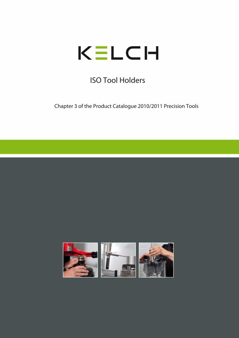
ISO - Steep Tapers

Kelch GmbH · Tel.: +49 (0) 71 51 / 2 05 22 -0 · Fax: +49 (0) 71 51 / 2 05 22 -11 · [email protected] · www.kelchgmbh.de
DIN 69 871 Adapters ISO - HSK 3.22Collet Chucks 3.11 - 3.12Drill Chucks 3.18Fine Boring Tools 3.19Holding Arbors for Milling Cutters 3.15i-tec Shrink Fit Chucks 3.3 - 3.6i-tec SLOTT 3.7Reduction Sleeves 3.16 - 3.17Reduction Sleeves for Straight Shanks 3.8 - 3.10Shell End Mill Arbors 3.13 - 3.14Tool Blanks 3.21Tooling System KELCH FLEXIBORE 3.20
JIS B 6339 i-tec Shrink Fit Chucks 3.24 - 3.26Tooling System KELCH FLEXIBORE 3.27
®
®
®

Kelch GmbH · Tel.: +49(0)7151 /20522-0 · Fax: +49(0)7151 /20522-11 · [email protected] · www.kelchgmbh.de3.2
DIN 69 871-1 type AD/Bwith through-holefor central coolant supplyand for lateral coolant supplyvia the tool flange
Technical Data and Standard SpecificationISO Tool Holders DIN 69 871
DesignSteep taper acc. to DIN 69 871 with bore foridentification chip according to DIN 69 873. Hardened by means of a special low- distortion hardening process. Vickershardnesss 670 ± 40 HV 30 (HRC 58 ± 2). Hardness depth Eht = min. 0.5 mm. Taper-angle tolerance quality AT3 according to DIN 2080-1.
Taper surface roughness indexRz ≤ 0.001 mm.
For details of concentricity of steep taper to tool holder, refer to appropriate page of catalogue.
If there is no other specification:Case-hardened alloy steel with a coretensile strength after case hardening of min. 980 N/mm .
Prices and delivery conditions are shown in the corresponding price list valid at the time in question.
Manufacturer reserves the right to make technicalmodifications. All dimensions in mm.
ISO d1 d2 d3H7
d6- 0.1
d7- 0.5
d8 d9 l1- 0.3
40 44.45 M16 17 63.55 56.25 50 4 68.4050 69.85 M24 25 97.50 91.25 80 6 101.75
ISO l6- 0.4
l7- 0.4
e1± 0.1
e2 a f1 f2 f3
40 22.8 25.0 27 5 3.2 11.1 35 19.150 35.5 37.7 42 7 3.2 11.1 35 19.1
DIN 69 871-1 type AD with through-holefor central coolant supply
DIN 69 871IS
OSt
eep
Tape
rs
Design Standard Specification
MaterialMaterial
Standard Specification

3.3Kelch GmbH · Tel.: +49(0)7151 /20522-0 · Fax: +49(0)7151 /20522-11 · [email protected] · www.kelchgmbh.de
DIN 69 871
Standard Versioni-tec® Shrink Fit Chucks
Similar to DIN 69 882-8, type G
ISO
Stee
p Ta
pers
ISO d1 A d2 d3 l1 g L V kg
40 3 70 311.0011.292 12 17 - - 138 10 0.940 3 120 311.0012.292 12 17 - - 188 10 0.940 4 70 311.0013.292 12 17 - - 138 10 0.940 4 120 311.0014.292 12 17 - - 188 10 0.940 5 70 311.0015.292 12 17 - - 138 10 0.940 5 120 311.0016.292 12 17 - - 188 10 0.940 6 80 311.0001.292 21 31 36 M 5 148 10 1.140 6 120 311.0031.292 21 32 36 M 5 188 10 1.340 8 80 311.0002.292 21 31 36 M 6 148 10 1.140 8 120 311.0032.292 21 32 36 M 6 188 10 1.340 10 80 311.0003.292 24 34 41 M 8 x 1 148 10 1.140 10 120 311.0033.292 24 34 41 M 8 x 1 188 10 1.340 12 80 311.0004.292 24 34 47 M10 x 1 148 10 1.240 12 120 311.0034.292 24 34 47 M10 x 1 188 10 1.340 14 80 311.0005.292 27 37 47 M10 x 1 148 10 1.240 16 80 311.0006.292 27 37 50 M12 x 1 148 10 1.240 16 120 311.0036.292 27 36 50 M12 x 1 188 10 1.440 18 80 311.0007.292 33 43 50 M12 x 1 148 10 1.240 20 80 311.0008.292 33 43 52 M16 x 1 148 10 1.240 20 120 311.0038.292 33 44 52 M16 x 1 188 10 1.640 25 100 311.0009.292 44 50 58 M16 x 1 168 10 1.7
50 6 80 311.0001.291 21 31 36 M 5 182 10 2.950 8 80 311.0002.291 21 31 36 M 6 182 10 2.950 10 80 311.0003.291 24 34 41 M 8 x 1 182 10 3.050 12 80 311.0004.291 24 34 47 M10 x 1 182 10 3.050 14 80 311.0005.291 27 37 47 M10 x 1 182 10 3.050 16 80 311.0006.291 27 37 50 M12 x 1 182 10 3.050 18 80 311.0007.291 33 43 50 M12 x 1 182 10 3.150 20 80 311.0008.291 33 43 52 M16 x 1 182 10 3.150 25 100 311.0009.291 44 53 58 M16 x 1 202 10 3.550 32 100 311.0010.291 44 56 61 M16 x 1 202 10 3.4
For adjusting screws see accessories page 7.13.
UseISO according to DIN 69 871-1, type AD/B.Permissible concentricity deviation of ISO taper to location hole d1 = 0.003 mm (measured at 3 x D cantilever length).Chucks are fine balanced according toISO 1940-1 G 2.5 at 25,000 minThe clamping diamter is designed for a shank tolerance of h6.
Standard SpecificationAdjusting screw for length adjustment(from Ø 6) is not included.
NoteFor further fine balancing of the chucks threaded holes are fitted on the coverage (for ISO 40).Can be rebalanced with threaded pins.
Coolant bores for type B are closed with threaded pins on delivery. If required, unscrew the threaded pins.Other designs and sizes are available on request.
Ref.no.Ref.no.
Use
Note
Standard Specification

3.4 Kelch GmbH · Tel.: +49(0)7151 /20522-0 · Fax: +49(0)7151 /20522-11 · [email protected] · www.kelchgmbh.de
DIN 69 871
Similar to DIN 69 882-8, type G
Conical Versioni-tec® Shrink Fit Chucks
ISO
Stee
p Ta
pers
ISO d1 A d2 d3 d4 l1 l2 g L V kg
40 6 160 311.0081.292 21 27 42 36 90 M 5 228 10 1.540 8 160 311.0082.292 21 27 42 36 90 M 6 228 10 1.540 10 160 311.0083.292 24 34 40 41 100 M 8 x 1 228 10 1.740 12 160 311.0084.292 24 34 40 47 100 M10 x 1 228 10 1.640 14 160 311.0085.292 27 36 42 47 100 M10 x 1 228 10 1.840 16 160 311.0086.292 27 36 42 50 100 M12 x 1 228 10 1.740 18 160 311.0047.292 33 44 -- 50 -- M12 x 1 228 10 2.140 20 160 311.0048.292 33 44 -- 52 -- M16 x 1 228 10 2.140 25 160 311.0049.292 44 50 -- 58 -- M16 x 1 228 10 2.6
50 6 160 311.0081.291 21 27 46 36 75 M 5 262 10 3.450 6 200 311.0091.291 21 27 50 36 130 M 5 302 10 3.750 8 160 311.0082.291 21 27 43 36 85 M 6 262 10 3.350 8 200 311.0092.291 21 27 50 36 130 M 6 302 10 3.750 10 160 311.0083.291 24 34 49 41 90 M 8 x 1 262 10 3.650 10 200 311.0093.291 24 34 49 41 130 M 8 x 1 302 10 3.850 12 160 311.0084.291 24 34 49 47 90 M10 x 1 262 10 3.650 12 200 311.0094.291 24 34 49 47 130 M10 x 1 302 10 3.850 14 160 311.0085.291 27 36 51 47 90 M10 x 1 262 10 3.750 14 200 311.0095.291 27 36 51 47 130 M10 x 1 302 10 4.050 16 160 311.0086.291 27 36 51 50 90 M12 x 1 262 10 3.650 16 200 311.0096.291 27 36 51 50 130 M12 x 1 302 10 3.950 18 160 311.0087.291 33 44 53 50 110 M12 x 1 262 10 4.050 18 200 311.0097.291 33 44 59 50 130 M12 x 1 302 10 4.550 20 160 311.0088.291 33 44 53 52 110 M16 x 1 262 10 3.850 20 200 311.0098.291 33 44 59 52 130 M16 x 1 302 10 4.350 25 160 311.0089.291 44 53 61 58 100 M16 x 1 262 10 4.550 25 200 311.0099.291 44 53 64 58 130 M16 x 1 302 10 5.250 32 160 311.0090.291 44 53 61 61 100 M16 x 1 262 10 4.450 32 200 311.0100.291 44 53 64 61 130 M16 x 1 302 10 5.0
For adjusting screws see accessories page 7.13.
DesignISO according to DIN 69 871-1, type AD/B with bore for identification chip.Permissible concentricity deviation of ISO taper to location hole d1 = 0.003 mm (measured at 3 x D cantilever length).Chucks are fine balanced according toISO 1940-1 G 2.5 at 25,000 minThe clamping diameter is designed for a shank tolerance of h6.
Standard SpecificationAdjusting screw for length adjustmentnot included.
NoteFor further fine balancing of the chucks threaded holes are fitted on the coverage (for ISO 40).Can be rebalanced with threaded pins.Coolant bores for type B are closed with
threaded pins on delivery. If required, unscrew the threaded pins.Other designs and sizes are available on request.
Ref.no.Ref.no.
Design
Note
Standard Specification

3.5Kelch GmbH · Tel.: +49(0)7151 /20522-0 · Fax: +49(0)7151 /20522-11 · [email protected] · www.kelchgmbh.de
DIN 69 871
Slim Versioni-tec® Shrink Fit Chucks
Similar to DIN 69 882-8, type G
ISO
Stee
p Ta
pers
ISO d1 A d2 d3 l1 g L V kg
40 3 120 311.0700.292 9 25 - - 188 - 1.040 3 160 311.0710.292 9 25 - - 228 - 1.140 4 120 311.0701.292 9 25 - - 188 - 1.040 4 160 311.0711.292 9 25 - - 228 - 1.140 5 120 311.0702.292 9 25 - - 188 - 1.040 5 160 311.0712.292 9 25 - - 228 - 1.140 6 120 311.0703.292 15 31 36 M 5 188 10 1.140 6 160 311.0713.292 15 30 36 M 5 228 10 1.340 8 120 311.0704.292 15 31 36 M 6 188 10 1.140 8 160 311.0714.292 15 30 36 M 6 228 10 1.340 10 120 311.0705.292 18 34 41 M 8 x 1 188 10 1.240 10 160 311.0715.292 18 32 41 M 8 x 1 228 10 1.440 12 120 311.0706.292 18 34 47 M10 x 1 188 10 1.140 12 160 311.0716.292 18 32 47 M10 x 1 228 10 1.6
50 3 120 311.0700.291 9 25 - - 222 - 2.850 3 160 311.0710.291 9 25 - - 262 - 2.950 4 120 311.0701.291 9 25 - - 222 - 2.850 4 160 311.0711.291 9 25 - - 262 - 2.950 5 120 311.0702.291 9 25 - - 222 - 2.850 5 160 311.0712.291 9 25 - - 262 - 2.950 6 120 311.0703.291 15 31 36 M 5 222 10 2.950 6 160 311.0713.291 15 30 36 M 5 262 10 3.150 8 120 311.0704.291 15 31 36 M 6 222 10 2.950 8 160 311.0714.291 15 30 36 M 6 262 10 3.150 10 120 311.0705.291 18 34 41 M 8 x 1 222 10 3.050 10 160 311.0715.291 18 32 41 M 8 x 1 262 10 3.250 12 120 311.0706.291 18 34 47 M10 x 1 222 10 2.950 12 160 311.0716.291 18 32 47 M10 x 1 262 10 3.1
DesignISO according to DIN 69 871-1, type AD/B with bore for identification chip.Permissible concentricity deviation of ISO taper to location hole d1 = 0.003 mm (measured at 3 x D cantilever length).Chucks are fine balanced according toISO 1940-1 G 2.5 at 25,000 min
The clamping diameter is designed for a shank tolerance of h6.
Standard SpecificationAdjusting screw for length adjustment(from Ø 6) not included.
NoteCoolant bores for type B are closed with threaded pins on delivery. If required, unscrew the threaded pins.Other designs and sizes are available on request.
Ref.no.Ref.no.
Design
Standard Specification
Note

3.6 Kelch GmbH · Tel.: +49(0)7151 /20522-0 · Fax: +49(0)7151 /20522-11 · [email protected] · www.kelchgmbh.de
DIN 69 871
Similar to DIN 69 882-8, type G
Ultra Short Versioni-tec® Shrink Fit Chucks
ISO
Stee
p Ta
pers
ISO d1 A d2 d3 l1 L kg
40 10 65 311.4353.292 26 33 41 133 1.040 12 65 311.4354.292 26 33 45 133 1.040 16 65 311.4356.292 29 36 52 133 1.040 20 65 311.4358.292 35 42 54 133 1.140 25 75 311.4359.292 45 50 59 143 1.4
ISO according to DIN 69 871-1, type AD/B with bore for identification chip.Permissible concentricity deviation of ISO taper to location hole d1 = 0.003 mm (measured at 3 x D cantilever length).
Chucks are fine balanced according to ISO 1940-1 G 2.5 at 25,000 minThe clamping diameter is designed for a shank tolerance of h6. With closable Cool Stream bores.
NoteCoolant bores for type B are closed with threaded pins on delivery. If required, unscrew the threaded pins.Other designs and sizes are available on request.
Ref.no.Ref.no.
DesignDesign Note

3.7Kelch GmbH · Tel.: +49(0)7151 /20522-0 · Fax: +49(0)7151 /20522-11 · [email protected] · www.kelchgmbh.de
DIN 69 871
i-tec®SLOTT
ISO
Stee
p Ta
pers
ISO d1 A Ref.no. d2 d3 l1 g L V kg
40 3 80 285.0000.292 19 22 - - 149 - 0.840 4 80 285.0002.292 19 22 - - 149 - 0.840 5 80 285.0003.292 19 22 - - 149 - 0.840 6 80 285.0004.292 19 22 35 M 6 149 5 0.940 7 80 285.0005.292 19 22 35 M 6 149 5 0.940 8 80 285.0006.292 19 22 35 M 6 149 5 0.940 9 80 285.0007.292 19 22 37 M 6 149 5 0.940 10 80 285.0008.292 22 22 37 M 6 149 5 1.040 11 80 285.0009.292 22 22 37 M 6 149 5 1.040 12 80 285.0010.292 27 22 37 M 6 149 5 1.040 12 80 285.0020.292 27 30 37 M 6 149 5 1.140 16 80 285.0012.292 27 30 40 M 6 149 5 1.1
For adjusting screws see accessories page 7.13.For shrink rings see accessories page 7.2.
DesignISO according to DIN 69 871-1, type AD/B.The clamping diameter is designed for a shank tolerance of h9.
Shrink ring and adjusting screw for length adjustment (from Ø 6) are included.
NoteCoolant bores for type B are closed with threaded pins on delivery. If required, unscrew the threaded pins.Other designs and sizes are available on request.
Standard Specification
Ref.no.
Design Standard Specification Note

3.8 Kelch GmbH · Tel.: +49(0)7151 /20522-0 · Fax: +49(0)7151 /20522-11 · [email protected] · www.kelchgmbh.de
DIN 69 871
DIN 6359-2
with Lateral Driving Surface (Weldon)Reduction Sleeves for Straight Shanks
ISO
Stee
p Ta
pers
ISO d1 A d2 l1 l2 L d1tolerance
kg
40 6 50 420.0051.292 25 35 31 118 + 0.005 0.940 6 100 420.0060.292 25 35 81 168 + 0.005 1.140 8 50 420.0052.292 28 35 31 118 + 0.005 0.940 8 100 420.0061.292 28 35 81 168 + 0.005 1.140 10 50 420.0053.292 35 39 31 118 + 0.005 1.040 10 100 420.0062.292 35 39 81 168 + 0.005 1.440 12 50 420.0054.292 42 44 31 118 + 0.005 1.240 12 100 420.0063.292 42 44 81 168 + 0.005 1.740 14 50 420.0058.292 44 44 31 118 + 0.005 1.240 14 100 420.0064.292 44 44 81 168 + 0.005 1.740 16 63 420.0055.292 48 47 44 131 + 0.005 1.240 16 100 420.0065.292 48 47 81 168 + 0.005 1.740 18 63 420.0059.292 50 47 44 131 + 0.005 1.540 18 100 420.0066.292 50 47 81 168 + 0.005 1.940 20 63 420.0056.292 52 49 44 131 + 0.007 1.340 20 100 420.0067.292 52 49 81 168 + 0.007 1.840 25 100 420.0057.292 65 54 81 168 + 0.007 2.340 32 100 420.0068.292 72 58 81 168 + 0.007 2.5
50 6 63 420.0051.291 25 35 44 165 + 0.005 2.750 6 100 420.0071.291 25 35 81 202 + 0.005 2.850 8 63 420.0052.291 28 35 44 165 + 0.005 2.750 8 100 420.0072.291 28 35 81 202 + 0.005 2.950 10 63 420.0053.291 35 39 44 165 + 0.005 2.950 10 100 420.0073.291 35 39 81 202 + 0.005 3.250 12 63 420.0054.291 42 44 44 165 + 0.005 3.050 12 100 420.0074.291 42 44 81 202 + 0.005 3.350 14 63 420.0064.291 44 44 44 165 + 0.005 3.050 14 100 420.0075.291 44 44 81 202 + 0.005 3.450 16 63 420.0055.291 48 47 44 165 + 0.005 3.050 16 100 420.0076.291 48 47 81 202 + 0.005 3.550 18 63 420.0068.291 50 47 44 165 + 0.005 3.050 18 100 420.0077.291 50 47 81 202 + 0.005 3.4
Ref.no.Ref.no.

3.9Kelch GmbH · Tel.: +49(0)7151 /20522-0 · Fax: +49(0)7151 /20522-11 · [email protected] · www.kelchgmbh.de
DIN 69 871
with Lateral Driving Surface (Weldon)Reduction Sleeves for Straight Shanks
DIN 6359-2
ISO
Stee
p Ta
pers
For clamping screws see accessories page 7.16.
UseFor holding shank tools with lateral driving surface, DIN 1835 type B and DIN 6535 type HB.
DesignISO according to DIN 69 871-1, type AD/B.Permissible concentricity deviation of ISO to location hole d1 = 0.003 mm.
ISO 40 chucks are balanced according to ISO 1940-1 G 6.3 at 12,000 minISO 50 chucks are balanced according to ISO 1940-1 G 6.3 at 8,000 min
Standard SpecificationClamping screw included.From location hole d1 = 25 mm 2 clamping screws are included.
NoteFor an increased machining accuracy the bore tolerance is much reduced compared to DIN 1835. Coolant bores for type B are closed with threaded pins on delivery. If required, unscrew the threaded pins.Other designs and styles are available on request.
ISO d1 A d2 l1 l2 L Toleranzvon d1
kg
50 20 63 420.0056.291 52 49 44 165 + 0.007 3.150 20 100 420.0078.291 52 49 81 202 + 0.007 3.650 25 80 420.0057.291 65 54 61 182 + 0.007 3.750 25 100 420.0079.291 65 54 81 202 + 0.007 4.450 32 100 420.0058.291 72 58 81 202 + 0.007 4.550 40 100 420.0059.291 80 68 81 202 + 0.007 4.7
Ref.no.Ref.no.
Use
Design Standard Specification
Note

3.10 Kelch GmbH · Tel.: +49(0)7151 /20522-0 · Fax: +49(0)7151 /20522-11 · [email protected] · www.kelchgmbh.de
DIN 69 871
DIN 6359-2
with Inclined Clamping Surface (Whistle Notch)Reduction Sleeves for Straight Shanks
ISO
Stee
p Ta
pers
ISO d1 A d2 l1 l2 g L d1tolerance
V kg
40 6 50 420.0151.292 25 35 31 M 5 118 + 0.005 10 0.940 8 50 420.0152.292 28 35 31 M 6 118 + 0.005 10 0.940 10 50 420.0153.292 35 39 31 M 8 118 + 0.005 10 1.040 12 50 420.0154.292 42 44 31 M10 118 + 0.005 10 1.140 14 50 420.0164.292 44 44 31 M10 118 + 0.005 10 1.240 16 63 420.0155.292 48 47 44 M12 131 + 0.005 10 1.240 18 63 420.0168.292 50 47 44 M12 131 + 0.005 10 1.540 20 63 420.0156.292 52 49 44 M16 131 + 0.007 10 1.940 25 100 420.0157.292 65 54 81 M20 168 + 0.007 10 2.340 32 100 420.0158.292 72 58 81 M20 168 + 0.007 10 2.5
50 6 63 420.0151.291 25 35 44 M 5 165 + 0.005 10 2.750 8 63 420.0152.291 28 35 44 M 6 165 + 0.005 10 2.850 10 63 420.0153.291 35 39 44 M 8 165 + 0.005 10 2.950 12 63 420.0154.291 42 44 44 M10 165 + 0.005 10 2.950 14 63 420.0164.291 44 44 44 M10 165 + 0.005 10 3.050 16 63 420.0155.291 48 47 44 M12 165 + 0.005 10 3.050 18 63 420.0168.291 50 47 44 M12 165 + 0.005 10 3.050 20 63 420.0156.291 52 49 44 M16 165 + 0.005 10 3.150 25 80 420.0157.291 65 54 61 M20 182 + 0.007 10 3.850 32 100 420.0158.291 72 58 81 M20 202 + 0.007 10 4.5
For clamping screws see accessories page 7.16.For adjusting screws see accessories page 7.13.
UseFor holding shank tools with inclined clamping surface (2°), DIN 1835 type E and DIN 6535 type HE.
DesignISO according to DIN 69 871-1, type AD/B.Permissible concentricity deviation of ISO taper to location hole d1 = 0.003 mm.ISO 40 chucks are balanced according to ISO 1940-1 G 6.3 at 12,000 min
ISO 50 chucks are balanced according to ISO 1940-1 G 6.3 at 8,000 min
Standard SpecificationClamping screw and adjusting screw included. From location hole d1 = 25 mm 2 clamping screws are included.
NoteFor an increased machining accuracy the bore tolerance is much reduced compared
to DIN 1835. Bored through adjusting screw for coolant.Coolant bores for type B are closed with threaded pins on delivery. If required, unscrewthe threaded pins.Other designs and sizes are availableon request.
Ref.no.Ref.no.
Use
Design
Standard Specification
Note

3.11Kelch GmbH · Tel.: +49(0)7151 /20522-0 · Fax: +49(0)7151 /20522-11 · [email protected] · www.kelchgmbh.de
DIN 69 871
for ER/ESX ER-11/16 with Internal ThreadCollet Chucks
DIN ISO 15488 (DIN 6499)
ISO
Stee
p Ta
pers
ISO Clampingrange
A d1 d2 D l1 l2 g L V kg
40 0.5 - 7 63 698.0061.292 -- 18.5 19 -- 18 M 6 131 10 0.940 0.5 - 7 100 698.0062.292 -- 18.5 19 -- 18 M 6 168 10 0.940 0.5 - 10 63 698.0051.292 -- 28 28 -- 27 M12 131 10 0.940 0.5 - 10 100 698.0052.292 -- 28 28 -- 27 M12 168 10 1.140 0.5 - 10 160 698.0053.292 46 28 28 85 27 M12 228 10 1.6
50 0.5 - 10 100 698.0051.291 -- 28 28 -- 27 M12 202 10 2.950 0.5 - 10 160 698.0052.291 78 28 28 85 27 M12 262 10 3.4
For adjusting screws see accessories page 7.13.For further accessories such as collets, clamping nuts or clamping keys see accessories from page 7.3 to page 7.8.
UseFor clamping tools with straight shankaccording to DIN ISO 15488 (DIN 6499) type A and B.
DesignISO according to DIN 69 871-1, type AD/B.Permissible concentricity deviation of ISO taper to inner taper 0.003 mm. Chucks are balanced without clamping nut.
ISO 40 chucks are balanced according to ISO 1940-1 G 6.3 at 12,000 minISO 50 chucks are balanced according to ISO 1940-1 G 6.3 at 8,000 minClamping nut is balanced according to ISO 1940-1 G 6.3 at 18,000 min
Standard SpecificationCollet chuck including clamping nut.
NoteCollet chucks are equipped with internalthread for adjusting screws.Coolant bores for type B are closed with threaded pins on delivery. If required, unscrew the threaded pins.Other designs and sizes are available on request.
Ref.no.Ref.no.
Use
Design
Standard Specification
Note

3.12 Kelch GmbH · Tel.: +49(0)7151 /20522-0 · Fax: +49(0)7151 /20522-11 · [email protected] · www.kelchgmbh.de
DIN 69 871
DIN ISO 15488 (DIN 6499)
for ER/ESX ER-25/32/40 for Internal ThreadCollet Chucks
ISO
Stee
p Ta
pers
ISO Clampingrange
A D l1 g L V kg
40 1 - 16 70 697.0050.292 42 36 M16 138 10 0.840 1 - 16 100 697.0055.292 42 36 M16 168 10 1.240 2 - 20 70 697.0051.292 50 40 M16 138 10 1.040 2 - 20 100 697.0053.292 50 40 M16 168 10 1.340 3 - 26 80 697.0052.292 63 58 M16 148 10 1.540 3 - 26 120 697.0054.292 63 58 M16 188 10 1.6
50 3 - 26 80 697.0052.291 63 58 M16 182 10 3.250 3 - 26 120 697.0053.291 63 58 M16 222 10 3.2
For further accessories such as collets, clamping nuts or clamping keys see accessories from page 7.3 to page 7.8.
UseFor clamping tools with straight shankaccording to DIN ISO 15488 (DIN 6499) type A and B.
DesignISO according to DIN 69 871-1, type AD/B.Permissible concentricity deviation of ISO taper to inner taper 0.003 mm.Chucks are balanced without clamping nut.
ISO 40 chucks are balanced according to ISO 1940-1 G 6.3 at 12,000 minISO 50 chucks are balanced according to ISO 1940-1 G 6.3 at 8,000 minClamping nut is balanced according to ISO 1940-1 G 6.3 at 18,000 min
Standard SpecificationCollet chuck including clamping nut.
NoteCollet chucks are equipped with internalthread for adjusting screws.Coolant bores for type B are closed with threaded pins on delivery. If required unscrew the threaded pins.Other designs and sizes are available on request.
Ref.no.Ref.no.
Use
Design
Standard Specification
Note

3.13Kelch GmbH · Tel.: +49(0)7151 /20522-0 · Fax: +49(0)7151 /20522-11 · [email protected] · www.kelchgmbh.de
DIN 69 871
for Milling Cutters with Longitudinal Slot or Tenon DriveShell End Mill Arbors
DIN 6358
ISO
Stee
p Ta
pers
ISO d1 A d2 l3 l4 L A1 kg
40 16 55 489.0011.292 32 17 27 140 45 1.140 16 100 489.0031.292 32 17 27 185 90 1.440 22 55 489.0012.292 40 19 31 142 43 1.340 22 100 489.0032.292 40 19 31 187 88 1.840 27 55 489.0013.292 48 21 33 144 43 1.540 27 100 489.0033.292 48 21 33 189 88 2.140 32 60 489.0004.292 58 24 38 152 46 1.840 32 100 489.0034.292 58 24 38 192 88 2.640 40 60 489.0005.292 70 27 41 155 46 2.1
50 16 55 489.0001.291 32 17 27 174 45 2.950 22 55 489.0002.291 40 19 31 176 43 3.050 22 100 489.0032.291 40 19 31 221 88 3.550 27 55 489.0003.291 48 21 33 178 43 3.250 27 100 489.0033.291 48 21 33 223 88 3.850 32 55 489.0004.291 58 24 38 181 41 3.750 32 100 489.0034.291 58 24 38 226 86 4.550 40 55 489.0005.291 70 27 41 184 41 4.050 40 100 489.0035.291 70 27 41 229 86 5.350 50 70 489.0006.291 90 30 46 202 54 5.5
For further accessories such as cutter retaining screws, keys, feather keys or drive rings see accessories from page 7.16 to page 7.17.
UseFor clamping shell end mills and milling cutters with longitudinal slot or tenon drive.
DesignISO according to DIN 69 871-1, type AD/B.Permissible concentricity deviation of ISO taper to arbor d1 = 0.01 mm.ISO 40 chucks are balanced according to
ISO 1940-1 G 6.3 at 12,000 minISO 50 chucks are balanced according to ISO 1940-1 G 6.3 at 8,000 minCutter drive according to DIN 138.
Standard SpecificationCutter retaining screw, feather key with withdrawal thread and drive ring included.
NoteCoolant bores for type B are closed with threaded pins on delivery. If required, unscrew the threaded pins.Other designs and sizes are available on request.
Ref.no.Ref.no.
Use
Design
Standard Specification
Note

3.14 Kelch GmbH · Tel.: +49(0)7151 /20522-0 · Fax: +49(0)7151 /20522-11 · [email protected] · www.kelchgmbh.de
DIN 69 871
with Enlarged Contact DiameterShell End Mill Arbors
ISO
Stee
p Ta
pers
ISO d1 A d2 l3 L kg
40 16 35 579.0005.292 40 17 120 0.940 22 35 579.0001.292 50 19 122 1.040 27 35 579.0002.292 50 21 124 1.140 32 50 579.0003.292 78 24 142 1.340 40 50 579.0004.292 89 27 145 1.6
50 22 35 579.0001.291 50 19 156 2.950 27 40 579.0002.291 60 21 163 3.350 32 50 579.0003.291 78 24 176 3.650 40 50 579.0004.291 89 27 179 4.250 50 50 579.0005.291 120 30 182 5.2
For further accessories such as cutter retaining screws, keys or drive keys see accessories from page 7.16 to page 7.18.For size 40 x 27 use drive key ref.no. 36.020.
UseFor clamping shell end mills and milling cutters with tenon drive.
DesignISO according to DIN 69 871-1, type AD/B.Permissible concentricity deviation of ISO taper to arbor d1 = 0.01 mm.ISO 40 chucks are balanced according to ISO 1940-1 G 6.3 at 12,000 min
ISO 50 chucks are balanced according to ISO 1940-1 G 6.3 at 8,000 minCentral boring for coolant supply.Clamping diameter 40 with 4 threaded holes for holding cutters with tool holdingaccording to DIN 2079.
Standard SpecificationCutter retaining screw and tightened drive keys included.
NoteCoolant bores for type B are closed with threaded pins on delivery. If required, unscrew the threaded pins .Other designs and sizes are available on request.
Ref.no.Ref.no.
Use
Design
Standard Specification
Note

3.15Kelch GmbH · Tel.: +49(0)7151 /20522-0 · Fax: +49(0)7151 /20522-11 · [email protected] · www.kelchgmbh.de
DIN 69 871
with Internal CenteringHolding Arbors for Milling Cutters
ISO
Stee
p Ta
pers
ISO d1 A d2 d4 d5 L kg
40 40 60 478.0003.292 89.3 M 12 66.7 158 2.3
50 40 70 478.0003.291 89.3 M 12 66.7 202 4.050 60 70 478.0005.291 129.1 M 16 101.6 212 7.3
DesignISO according to DIN 69 871-1, type AD/B.Permissible concentricity deviation of ISO taper to arbor d1 = 0.02 mm.Tool side according to DIN 2079.
Standard SpecificationTightened drive keys included.
NoteOther designs and sizes are available on request.
Ref.no.Ref.no.
Design Standard Specification Note

3.16 Kelch GmbH · Tel.: +49(0)7151 /20522-0 · Fax: +49(0)7151 /20522-11 · [email protected] · www.kelchgmbh.de
DIN 69 871
for Morse Tapers with TangReduction Sleeves
ISO
Stee
p Ta
pers
Ref.no.MT A d1 l1 L kg
40 1 50 454.0001.292 25 31 118 0.940 2 50 454.0002.292 32 31 118 0.940 3 70 454.0003.292 40 51 138 1.040 4 95 454.0004.292 48 76 163 1.3
50 1 45 454.0001.291 25 26 147 2.650 2 60 454.0002.291 32 41 162 2.750 3 65 454.0003.291 40 46 167 2.750 4 95 454.0004.291 48 76 197 3.050 5 105 454.0005.291 63 86 207 3.2
DesignISO according to DIN 69 871-1, type AD.Permissible concentricity deviation of ISO taper to inner taper 0.008 mm.
ISO 40 chucks are balanced according to ISO 1940-1 G 6.3 at 12,000 min .ISO 50 chucks are balanced according to ISO 1940-1 G 6.3 at 8,000 min .
NoteOther designs and sizes are available on request.
Ref.no.
Design Note
ISO

3.17Kelch GmbH · Tel.: +49(0)7151 /20522-0 · Fax: +49(0)7151 /20522-11 · [email protected] · www.kelchgmbh.de
DIN 69 871
for Morse Tapers with Thread Reduction Sleeves
ISO
Stee
p Ta
pers
ISO MT A d1 l1 g L kg
40 1 50 458.0001.292 25 31 M 6 118 0.940 2 50 458.0002.292 32 31 M10 118 0.940 3 70 458.0003.292 40 51 M12 138 1.140 4 (95) 110 458.0004.292 63 91 M16 178 2.2
50 1 45 458.0001.291 25 26 M 6 147 2.750 2 60 458.0002.291 32 41 M10 162 3.050 3 65 458.0003.291 40 46 M12 167 3.050 4 (70) 85 458.0004.291 63 66 M16 187 3.650 5 (100) 118 458.0005.291 78 99 M20 220 4.6
For further accessories such as retaining screws, keys or threaded rings see accessories from page 7.18 to page 7.19.
DesignISO according to DIN 69 871-1, type A.Permissible concentricity deviation of ISO taper to inner taper 0.008 mm.ISO 40 chucks are balanced according to ISO 1940-1 G 6.3 at 12,000 min
ISO 50 chucks are balanced according to ISO 1940-1 G 6.3 at 8,000 min
Standard SpecificationRetaining screw and threaded ring included.
NoteOther designs and sizes are available on request.
Ref.no.Ref.no.
Design
Standard Specification
Note

3.18 Kelch GmbH · Tel.: +49(0)7151 /20522-0 · Fax: +49(0)7151 /20522-11 · [email protected] · www.kelchgmbh.de
DIN 69 871
Drill Chucks
ISO
Stee
p Ta
pers
ISO Clampingrange
A D L kg
40 1 - 13 88 490.0050.292 50 156.5 1.340 3 - 16 88 490.0051.292 55 157.2 1.5
50 1 - 13 88 490.0050.291 50 189.9 3.050 3 - 16 88 490.0051.291 55 190.5 3.3
UseFor holding tools with straight shank for use in machining centres and NC machines.
DesignISO according to DIN 69 871-1, type AD/B.High precision and truth of running.For clockwise and anti-clockwise rotation.Simple to operate, clamping and releasing by an allen key.
NoteOther designs and sizes are availableon request.
Ref.no.Ref.no.
Use Design Note

3.19Kelch GmbH · Tel.: +49(0)7151 /20522-0 · Fax: +49(0)7151 /20522-11 · [email protected] · www.kelchgmbh.de
DIN 69 871
Fine Boring Tools
ISO
Stee
p Ta
pers
ISO d1 A Boring range d2 l1 L kg
40 16 90 493.0011.292 3 - 88.1 55 80 159 1.8
For boring bars see accessories page 7.21.
UseFor boring bars with a shank diameter of 16 mm. For precision boring with closetolerances and high surface finish qualityin the 3 to 88.1 mm diameter range.
Design- Setting accuracy of 0.01 mm or 0.002 mm
using a vernier scale- Micrometer spindle with a large scale for
exact setting and easy reading- Minimum backlash- Variable overhang bar length positions - Internal coolant capability for chip clearance
Standard SpecificationBoring bars to be ordered separately.
Ref.no.Ref.no.
Use Design Standard Specification

3.20 Kelch GmbH · Tel.: +49 (0) 71 51 / 2 05 22 -0 · Fax: +49 (0) 71 51 / 2 05 22 -11 · [email protected] · www.kelchgmbh.de
DIN 69 871
Tooling System KELCH FLEXIBORE
ISO
Stee
p Ta
pers
ISO d2 A l1 L kg
40 25 40 494.0301.292 21 108 0.840 32 40 494.0302.292 21 108 0.940 40 40 494.0303.292 21 108 1.040 50 40 494.0305.292 21 108 1.040 63 60 494.0304.292 41 128 1.5
50 25 40 494.0301.291 21 142 2.750 32 40 494.0302.291 21 142 2.750 40 40 494.0303.291 21 142 2.750 50 40 494.0306.291 21 142 2.850 63 40 494.0304.291 21 142 3.050 100 60 494.0305.291 41 162 4.5
For anti-fatigue bolts see accessories page 7.19.For allen keys see accessories page 7.19.
DesignISO according to DIN 69 871-1, type AD/B.Permissible concentricity deviation of ISO
taper to location hole 0.005 mm.Permissible axial runout deviation of ISO
taper to contact face 0.003 mm.
Standard SpecificationAnti-fatigue bolt and tightened driving dogs included.
NoteCoolant bores for type B are closed with
threaded pins on delivery. If required, unscrew the threaded pins.Other designs and sizes are available
Ref.no.Ref.no.
on request.
Design Standard Specification Note

3.21Kelch GmbH · Tel.: +49(0)7151 /20522-0 · Fax: +49(0)7151 /20522-11 · [email protected] · www.kelchgmbh.de
DIN 69 871
Tool Blanks
ISO
Stee
p Ta
pers
ISO d1 A L kg
40 40 250 517.0001.292 318 3.140 63 250 517.0002.292 318 6.3
50 50 315 517.0001.291 417 7.250 63 315 517.0002.291 417 9.550 95 315 517.0003.291 417 22.5
UseFor self-manufacturing special tools.
DesignTaper including flange hardened.Vickers hardness min. HV 670 kp/mm(min. HRC 58).
Taper ground, shank not ground, prepared to be finished, unhardened.Centre hole according to DIN 332 type R.
MaterialAlloyed case-hardened steel.
NoteWithout bore for identification chip. The dimensions quoted here for d1 are finished dimensions. Delivery with 0.5 mm allowance in the diameter. Other designs and sizes are available on request.
Use
Design
Material
Note
Ref.no.Ref.no.

3.22 Kelch GmbH · Tel.: +49(0)7151 /20522-0 · Fax: +49(0)7151 /20522-11 · [email protected] · www.kelchgmbh.de
DIN 69 871
Adapters ISO - HSK
ISO
Stee
p Ta
pers
ISO d1 A ± 0.01 l1 L kg
40 25 40 716.0001.292 20.9 108.4 0.840 32 40 716.0002.292 20.9 108.4 0.940 40 40 716.0003.292 20.9 108.4 1.040 50 40 716.0004.292 20.9 108.4 1.040 63 80 716.0005.292 60.9 148.4 1.6
50 25 40 716.0001.291 20.9 142 2.650 32 40 716.0002.291 20.9 142 2.750 40 40 716.0003.291 20.9 142 2.850 50 40 716.0004.291 20.9 142 2.950 63 40 716.0005.291 20.9 142 3.150 80 60 716.0006.291 40.9 162 3.850 100 100 716.0007.291 60.9 202 4.6
For clamping cartridges see accessories page 7.19.For cover rings see accessories page 7.20.
UseFor holding HSK tools according to ISO 12164-1; DIN 69 893-1, type A and C, d1 = nominal size HSK.
DesignISO according to DIN 69 871 AD.
Permissible concentricity deviation of ISO taper to inner taper 0.005 mm.
Standard SpecificationComplete with clamping cartridge and cover ring.
NoteWithout bore for identification chip. Special designs are available on request.
Ref.no.Ref.no.
Use
DesignStandard Specification
Note

Kelch GmbH · Tel.: +49 (0) 71 51 / 2 05 22 -0 · Fax: +49 (0) 71 51 / 2 05 22 -11 · [email protected] · www.kelchgmbh.de 3.23
JIS B 6339 - 1986 (MAS 403 BT)
Technical Data and Standard SpecificationISO Tool Holders JIS B 6339
DesignHardened by means of a special low- distortion hardening process. Vickershardness 670 ± 40 HV 30 (HRC 58 ± 2).Hardness depth Eht = min. 0.5 mm.Taper-angle tolerance quality AT 3 according to DIN 2080-1.
Taper surface roughness indexRz ≤ 0.001 mm.
For details of concentricity of hollow taper shank to tool holder, refer to appropriate page of catalogue.
MaterialIf there is no other specification:Case-hardened alloy steel with a coretensile strength after case hardening of min. 980 N/mm2.
NotePrices and delivery conditions are shown in the corresponding price list valid at the
Manufacturer reserves the right to maketechnical modifications. All dimensions in mm.
ISO d1 d2 d3H8
d6h8
d7 d9 l1± 0.15
l6- 0.2
40 44.45 M16 17 63 53 4 65.40 22.650 69.85 M24 25 100 85 6 101.80 35.4
ISO e1± 0.1
e2 a f1 f3
40 27 5 2 16.6 2750 42 7 3 23.2 38
JIS B 6339
ISO
Stee
p Ta
pers
time in question.
Design
Material
Note

3.24 Kelch GmbH · Tel.: +49(0)7151 /20522-0 · Fax: +49(0)7151 /20522-11 · [email protected] · www.kelchgmbh.de
JIS B 6339
Similar to DIN 69 882-8, type G
Standard Versioni-tec® Shrink Fit Chucks
ISO
Stee
p Ta
pers
ISO d1 A d2 d3 l1 g L V kg
40 3 80 311.0111.265 12 17 - - 146 - 1.140 4 80 311.0113.265 12 17 - - 146 - 1.140 5 80 311.0115.265 12 17 - - 146 - 1.140 6 90 311.0101.265 21 31 36 M 5 156 10 1.240 6 160 311.0151.265 21 32 36 M 5 226 10 1.640 8 90 311.0102.265 21 31 36 M 6 156 10 1.240 8 160 311.0152.265 21 32 36 M 6 226 10 1.640 10 90 311.0103.265 24 34 41 M 8 x 1 156 10 1.340 10 160 311.0153.265 24 34 41 M 8 x 1 226 10 1.740 12 90 311.0104.265 24 34 47 M10 x 1 156 10 1.340 12 160 311.0154.265 24 34 47 M10 x 1 226 10 1.740 14 90 311.0105.265 27 37 47 M10 x 1 156 10 1.340 14 160 311.0155.265 27 36 47 M10 x 1 226 10 1.740 16 90 311.0106.265 27 37 50 M12 x 1 156 10 1.340 16 160 311.0156.265 27 36 50 M12 x 1 226 10 1.840 18 90 311.0107.265 33 43 50 M12 x 1 156 10 1.440 18 160 311.0157.265 33 44 50 M12 x 1 226 10 2.240 20 90 311.0108.265 33 43 52 M16 x 1 156 10 1.440 20 160 311.0158.265 33 44 52 M16 x 1 226 10 2.140 25 100 311.0109.265 44 53 58 M16 x 1 166 10 1.840 25 160 311.0159.265 44 53 58 M16 x 1 226 10 2.6
50 6 100 311.0101.225 21 31 36 M 5 202 10 3.850 6 160 311.0151.225 21 32 36 M 5 262 10 4.150 8 100 311.0102.225 21 31 36 M 6 202 10 3.850 8 160 311.0152.225 21 32 36 M 6 262 10 4.150 10 100 311.0103.225 24 34 41 M 8 x 1 202 10 3.950 10 160 311.0153.225 24 34 41 M 8 x 1 262 10 4.250 12 100 311.0104.225 24 34 47 M10 x 1 202 10 3.850 12 160 311.0154.225 24 34 47 M10 x 1 262 10 4.250 14 100 311.0105.225 27 37 47 M10 x 1 202 10 3.950 14 160 311.0155.225 27 36 47 M10 x 1 262 10 4.350 16 100 311.0106.225 27 37 50 M12 x 1 202 10 3.850 16 160 311.0156.225 27 36 50 M12 x 1 262 10 4.250 18 100 311.0107.225 33 43 50 M12 x 1 202 10 4.050 18 160 311.0157.225 33 44 50 M12 x1 262 10 4.650 20 100 311.0108.225 33 43 52 M16 x 1 202 10 3.950 20 160 311.0158.225 33 44 52 M16 x 1 262 10 4.5
Ref.no. Ref.no.

3.25Kelch GmbH · Tel.: +49(0)7151 /20522-0 · Fax: +49(0)7151 /20522-11 · [email protected] · www.kelchgmbh.de
JIS B 6339
Standard Versioni-tec® Shrink Fit Chucks
Similar to DIN 69 882-8, type G
ISO
Stee
p Ta
pers
ISO d1 A d2 d3 l1 g L V kg
50 25 120 311.0109.225 44 57 58 M16 x 1 222 10 4.550 25 160 311.0159.225 44 53 58 M16 x 1 262 10 5.050 32 120 311.0110.225 44 57 61 M16 x 1 222 10 4.350 32 160 311.0160.225 44 53 61 M16 x 1 262 10 4.9
For adjusting screws see accessories page 7.13.
DesignISO taper according to JIS B 6339.Coolant bores according to DIN 69 871, type AD/B.Permissible concentricity deviation of ISO taper to location hole d1 = 0.003 mm (measured at 3 x D cantilever length).Chucks are balanced according to ISO 1940-1G 2.5 at 18,000 min
The clamping diameter is designed for ashank tolerance of h6.
Standard SpecificationAdjusting screw for length adjustment(from Ø 6) not included.
NoteFor further fine balancing of the chucks
threaded holes are fitted on the coverage (for ISO 40).Can be rebalanced with threaded pins.Coolant bores for type B are closed with threaded pins on delivery. If required, unscrew the threaded pins.Other designs and sizes are available on request.
Ref.no.
Design
Standard Specification
Note
Ref.no.

3.26 Kelch GmbH · Tel.: +49(0)7151 /20522-0 · Fax: +49(0)7151 /20522-11 · [email protected] · www.kelchgmbh.de
JIS B 6339
Similar to DIN 69 882-8, type G
Conical Versioni-tec® Shrink Fit Chucks
ISO
Stee
p Ta
pers
ISO d1 A d2 d3 d4 l1 l2 g L V kg
40 6 160 311.0181.265 21 27 42 36 80 M 5 226 10 1.740 8 160 311.0182.265 21 27 42 36 80 M 6 226 10 1.740 10 160 311.0183.265 24 34 40 41 90 M 8 x 1 226 10 1.840 12 160 311.0184.265 24 34 40 47 90 M10 x 1 226 10 1.740 14 160 311.0185.265 27 36 42 47 90 M10 x 1 226 10 1.940 16 160 311.0186.265 27 36 42 50 90 M12 x 1 226 10 1.8
50 6 160 311.0181.225 21 27 42 36 70 M 5 262 10 4.250 8 160 311.0182.225 21 27 42 36 70 M 6 262 10 4.250 10 160 311.0183.225 24 34 45 41 85 M 8 x 1 262 10 4.450 12 160 311.0184.225 24 34 45 47 85 M10 x 1 262 10 4.350 14 160 311.0185.225 27 36 47 47 85 M10 x 1 262 10 4.450 16 160 311.0186.225 27 36 47 50 85 M12 x 1 262 10 4.450 18 160 311.0187.225 33 44 55 50 85 M12 x 1 262 10 4.850 20 160 311.0188.225 33 44 55 52 85 M16 x 1 262 10 4.650 25 160 311.0189.225 44 53 63 58 75 M16 x 1 262 10 5.250 32 160 311.0190.225 44 53 63 61 75 M16 x 1 262 10 5.1
For adjusting screws see accessories page 7.13.
DesignISO tapers according to JIS B 6339.Coolant bores according to DIN 69 871, type AD/B.Permissible concentricity deviation of ISO taper to location hole d1 = 0.003 mm (measured at 3 x D cantilever length).Chucks are balanced according to ISO 1940-1 G 2.5 at 18,000 minThe clamping diameter is designed for a shank tolerance of h6.
Standard SpecificationAdjusting screw for length adjustmentnot included.
NoteFor further fine balancing of the chucks threaded holes are fitted on the coverage (for ISO 40).Can be rebalanced with threaded pins.Coolant bores for type B are closed with threaded pins on delivery. If required,
unscrew the threaded pins.Other designs and sizes are available on request.
Ref.no.Ref.no.
Design
Note
Standard Specification

3.27Kelch GmbH · Tel.: +49(0)7151 /20522-0 · Fax: +49(0)7151 /20522-11 · [email protected] · www.kelchgmbh.de
JIS B 6339
Tooling System KELCH FLEXIBORE
ISO
Stee
p Ta
pers
ISO d1 A l1 L kg
40 25 50 494.0103.265 23 115 1.040 32 50 494.0104.265 23 115 1.140 40 50 494.0101.265 23 115 1.140 50 50 494.0105.265 23 115 1.240 63 50 494.0102.265 23 115 1.4
50 25 60 494.0104.225 23 162 3.650 32 60 494.0105.225 23 162 3.750 40 60 494.0101.225 23 162 3.850 50 60 494.0106.225 22 162 3.950 63 60 494.0102.225 22 162 4.150 100 60 494.0103.225 32 162 4.8
For anti-fatigue bolts see accessories page 7.19.For allen keys see accessories page 7.19.
DesignISO according to JIS B 6339, type AD.Permissible concentricity deviation of ISO taper to location hole 0.005 mm.Permissible axial runout deviation of ISO taper to contact face 0.003 mm.
Standard SpecificationAnti-fatigue bolt and tightened driving dogs included.
NoteOther designs and sizes are available on request.
Ref.no.
Design Standard Specification Note
Ref.no.

www.kelchgmbh.de
As of September 2010 · Technical and design modi�cations are subject to change without notice.
0720
7, 0
5/20
11
Prod
uct C
atal
goue
201
0/11
· Pre
cisi
on T
ools
Product Catalogue 2010/11 Precision Tools
HSK Tool Holders · Tool Holders with Polygonal ShankTool Holders with Steep Taper · FLEXIBORE
Tool Holders with Straight Shank · Shrinking Devices · Accessories
Germany(Headquarters)Kelch GmbHWerkstr. 30D-71384 Weinstadt Tel.: +49 (0) 71 51 / 2 05 22 -0 Fax: +49 (0) 71 51 / 2 05 22 [email protected]
EnglandKELCH UK Ltd.Unit 4 Cygnet DriveSwan Valley Business ParkGB-Northampton NN4 9BSTel.: +44 1604 58 38 00Fax: +44 1604 58 38 [email protected]
SwitzerlandKELCH AGWeihermattstr. 14CH-6260 ReidenTel.: +41 62 7 58 51-26Fax: +41 62 7 58 [email protected]
ChinaHarbin Measuring &Cutting Tool Group Co., Ltd.44 Heping RoadHarbin China 150040Tel.: +86 451 82 64 18 36Fax: +86 451 82 62 35 55www.links-china.com
USAKELCH Inc.1574 Barclay Blvd.Bu�alo Grove IL 60089Tel.: +1 847 4 59-96 00Fax: +1 847 4 59-96 [email protected]