ISO 10110-7 / ISO 14997 Plus Surface Scratch & Dig ...Any scratch defect that is obscured by the...
20
ISO 10110-7 / ISO 14997 Plus Surface Scratch & Dig Evaluation Targets Usage and Applications Guide Version 1.1 © 2007, MLAI Max Levy Autograph, Inc.
Transcript of ISO 10110-7 / ISO 14997 Plus Surface Scratch & Dig ...Any scratch defect that is obscured by the...
ISO 10110-7 / ISO 14997 Plus Surface Scratch & Dig Evaluation Targets
Usage and Applications Guide
Version 1.1 © 2007, MLAI
Max Levy Autograph, Inc.
Max Levy Autograph, Inc. ISO 14997 PLUS Users Manual V1.1 - 2 -
Table of Contents
1. Target Features............................................................................................................... 3
Versions .......................................................................................................................... 3 Standard ISO 10110-7 Features ...................................................................................... 4
Circles ......................................................................................................................... 4 Scratches ..................................................................................................................... 4
Enhanced Features .......................................................................................................... 5 Ronchi Rulings............................................................................................................ 5 Linear Scale ................................................................................................................ 6 Grids............................................................................................................................ 6
Summary of Target Features (Table)...............................................................................7 2. Overview of the ISO 10110-7 Standard......................................................................... 8
The ISO 10110 Series ..................................................................................................... 8 ISO 10110 Part 7............................................................................................................. 9 Other Applicable Standards ............................................................................................ 9 Obtaining the Standard ................................................................................................... 9 Test Methods................................................................................................................. 10
3. Usage Guide.................................................................................................................. 11 General Description ...................................................................................................... 11 Handling........................................................................................................................ 11 Cleaning ........................................................................................................................ 11 General Usage Procedure.............................................................................................. 12
Direct Measurement Method (Transmission) ........................................................... 12 Method for Viewing in Reflection............................................................................ 13 Method of Classification........................................................................................... 13
4. Conventions of the Standard......................................................................................... 15 Notation......................................................................................................................... 15
Surface Imperfection Tolerances (Method 1) ........................................................... 15 Standard Surface Imperfection Artifacts ...................................................................... 16 Additional ISO 10110 Drawing Codes ......................................................................... 17
5. A Comparison to MIL STD Scratch Dig ..................................................................... 18 MIL-PRF-13830B to ISO 10110-7 Comparison Guide ........................................... 19
Max Levy Autograph, Inc. ISO 14997 PLUS Users Manual V1.1 - 3 -
1. Target Features
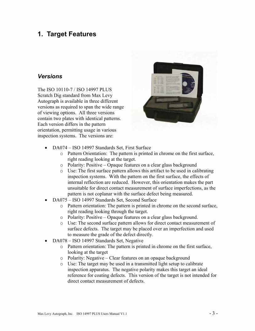
Versions The ISO 10110-7 / ISO 14997 PLUS Scratch Dig standard from Max Levy Autograph is available in three different versions as required to span the wide range of viewing options. All three versions contain two plates with identical patterns. Each version differs in the pattern orientation, permitting usage in various inspection systems. The versions are:
• DA074 – ISO 14997 Standards Set, First Surface o Pattern Orientation: The pattern is printed in chrome on the first surface,
right reading looking at the target. o Polarity: Positive – Opaque features on a clear glass background o Use: The first surface pattern allows this artifact to be used in calibrating
inspection systems. With the pattern on the first surface, the effects of internal reflection are reduced. However, this orientation makes the part unsuitable for direct contact measurement of surface imperfections, as the pattern is not coplanar with the surface defect being measured.
• DA075 – ISO 14997 Standards Set, Second Surface o Pattern orientation: The pattern is printed in chrome on the second surface,
right reading looking through the target. o Polarity: Positive – Opaque features on a clear glass background. o Use: The second surface pattern allows for direct contact measurement of
surface defects. The target may be placed over an imperfection and used to measure the grade of the defect directly.
• DA078 – ISO 14997 Standards Set, Negative o Pattern orientation: The pattern is printed in chrome on the first surface,
looking at the target o Polarity: Negative – Clear features on an opaque background o Use: The target may be used in a transmitted light setup to calibrate
inspection apparatus. The negative polarity makes this target an ideal reference for coating defects. This version of the target is not intended for direct contact measurement of defects.
Max Levy Autograph, Inc. ISO 14997 PLUS Users Manual V1.1 - 4 -
Standard ISO 10110-7 Features ISO 10110-7 lists a number of standard features to be included in a Scale Comparison Plate. These features are listed in Annex E of the standard, and are reprinted in this guide in Table 4.2. The ISO 14997 Scratch Dig Standards include all of the features described by the standard. These features are explained below:
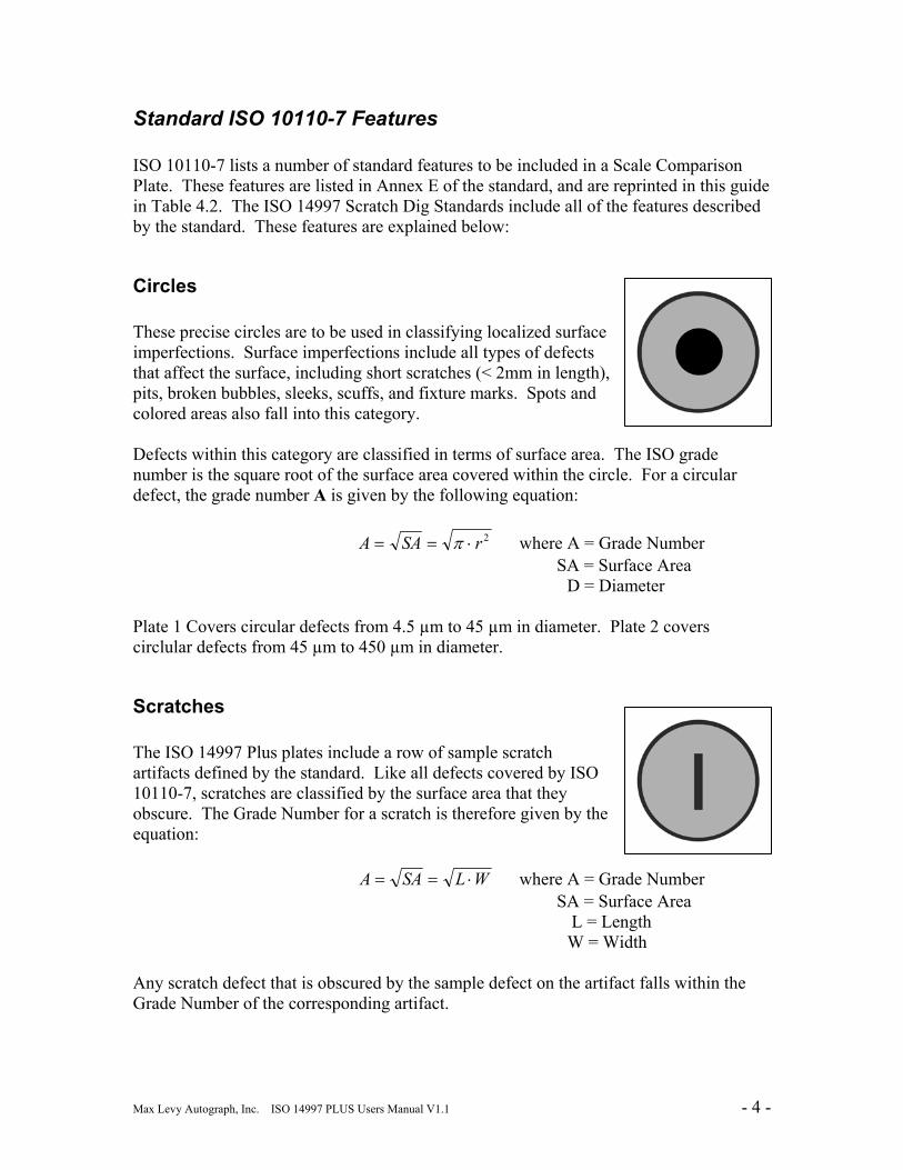
Circles These precise circles are to be used in classifying localized surface imperfections. Surface imperfections include all types of defects that affect the surface, including short scratches (< 2mm in length), pits, broken bubbles, sleeks, scuffs, and fixture marks. Spots and colored areas also fall into this category. Defects within this category are classified in terms of surface area. The ISO grade number is the square root of the surface area covered within the circle. For a circular defect, the grade number A is given by the following equation: 2rSAA ⋅== π where A = Grade Number SA = Surface Area D = Diameter Plate 1 Covers circular defects from 4.5 µm to 45 µm in diameter. Plate 2 covers circlular defects from 45 µm to 450 µm in diameter.
Scratches The ISO 14997 Plus plates include a row of sample scratch artifacts defined by the standard. Like all defects covered by ISO 10110-7, scratches are classified by the surface area that they obscure. The Grade Number for a scratch is therefore given by the equation: WLSAA ⋅== where A = Grade Number SA = Surface Area L = Length W = Width Any scratch defect that is obscured by the sample defect on the artifact falls within the Grade Number of the corresponding artifact.
Max Levy Autograph, Inc. ISO 14997 PLUS Users Manual V1.1 - 5 -
Note: According to ISO 10110-7 notation, any defect longer than 2mm is considered a long scratch. In classifying long scratches, only the width of the scratch is used. The sample scratch artifacts may be used to classify long scratches by only considering the width of the scratch. Section 5 of this guide provides a comparison of this ISO standard to the MIL-PRF-13830B standard.
Enhanced Features
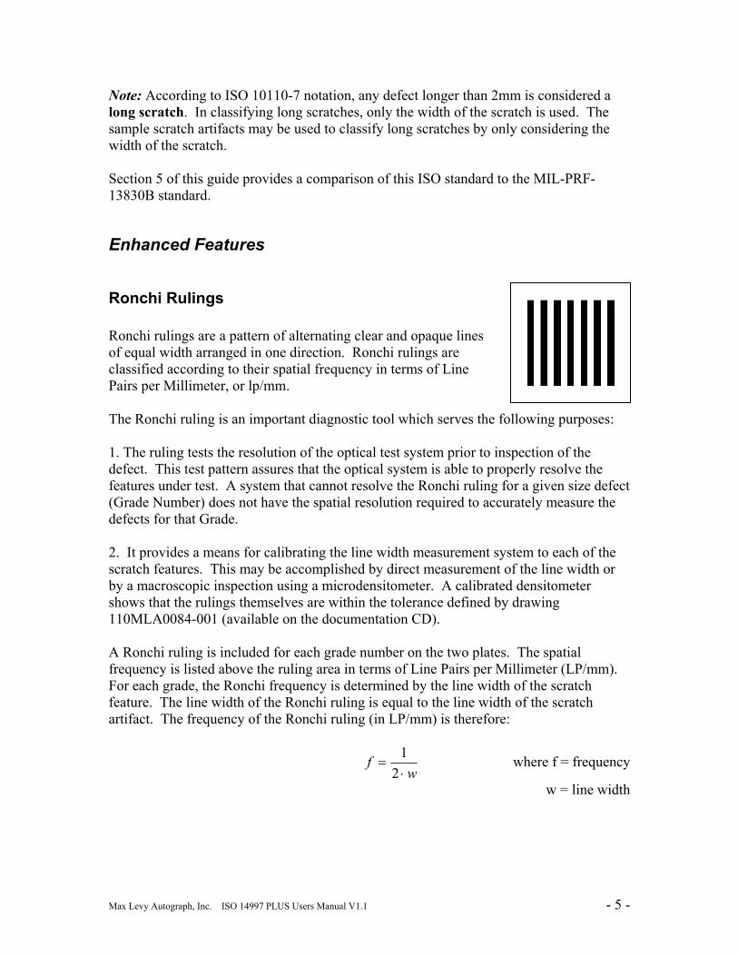
Ronchi Rulings Ronchi rulings are a pattern of alternating clear and opaque lines of equal width arranged in one direction. Ronchi rulings are classified according to their spatial frequency in terms of Line Pairs per Millimeter, or lp/mm. The Ronchi ruling is an important diagnostic tool which serves the following purposes: 1. The ruling tests the resolution of the optical test system prior to inspection of the defect. This test pattern assures that the optical system is able to properly resolve the features under test. A system that cannot resolve the Ronchi ruling for a given size defect (Grade Number) does not have the spatial resolution required to accurately measure the defects for that Grade. 2. It provides a means for calibrating the line width measurement system to each of the scratch features. This may be accomplished by direct measurement of the line width or by a macroscopic inspection using a microdensitometer. A calibrated densitometer shows that the rulings themselves are within the tolerance defined by drawing 110MLA0084-001 (available on the documentation CD). A Ronchi ruling is included for each grade number on the two plates. The spatial frequency is listed above the ruling area in terms of Line Pairs per Millimeter (LP/mm). For each grade, the Ronchi frequency is determined by the line width of the scratch feature. The line width of the Ronchi ruling is equal to the line width of the scratch artifact. The frequency of the Ronchi ruling (in LP/mm) is therefore:
w
f⋅
=2
1 where f = frequency
w = line width
Max Levy Autograph, Inc. ISO 14997 PLUS Users Manual V1.1 - 6 -
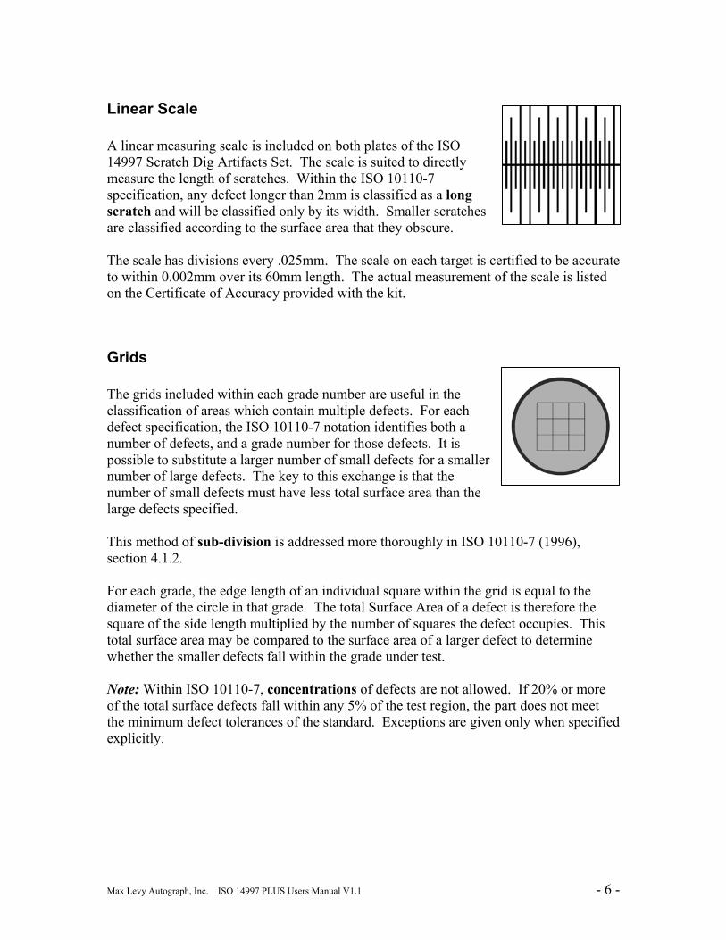
Linear Scale A linear measuring scale is included on both plates of the ISO 14997 Scratch Dig Artifacts Set. The scale is suited to directly measure the length of scratches. Within the ISO 10110-7 specification, any defect longer than 2mm is classified as a long scratch and will be classified only by its width. Smaller scratches are classified according to the surface area that they obscure. The scale has divisions every .025mm. The scale on each target is certified to be accurate to within 0.002mm over its 60mm length. The actual measurement of the scale is listed on the Certificate of Accuracy provided with the kit.
Grids The grids included within each grade number are useful in the classification of areas which contain multiple defects. For each defect specification, the ISO 10110-7 notation identifies both a number of defects, and a grade number for those defects. It is possible to substitute a larger number of small defects for a smaller number of large defects. The key to this exchange is that the number of small defects must have less total surface area than the large defects specified. This method of sub-division is addressed more thoroughly in ISO 10110-7 (1996), section 4.1.2. For each grade, the edge length of an individual square within the grid is equal to the diameter of the circle in that grade. The total Surface Area of a defect is therefore the square of the side length multiplied by the number of squares the defect occupies. This total surface area may be compared to the surface area of a larger defect to determine whether the smaller defects fall within the grade under test. Note: Within ISO 10110-7, concentrations of defects are not allowed. If 20% or more of the total surface defects fall within any 5% of the test region, the part does not meet the minimum defect tolerances of the standard. Exceptions are given only when specified explicitly.
Max Levy Autograph, Inc. ISO 14997 PLUS Users Manual V1.1 - 7 -
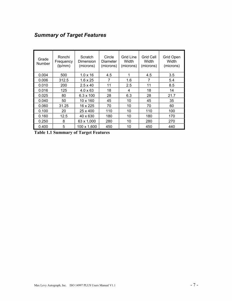
Summary of Target Features
Grade Number
Ronchi Frequency
(lp/mm)
Scratch Dimension (microns)
Circle Diameter (microns)
Grid Line Width
(microns)
Grid Cell Width
(microns)
Grid Open Width
(microns)
0.004 500 1.0 x 16 4.5 1 4.5 3.5 0.006 312.5 1.6 x 25 7 1.6 7 5.4 0.010 200 2.5 x 40 11 2.5 11 8.5 0.016 125 4.0 x 63 18 4 18 14 0.025 80 6.3 x 100 28 6.3 28 21.7 0.040 50 10 x 160 45 10 45 35 0.060 31.25 16 x 225 70 10 70 60 0.100 20 25 x 400 110 10 110 100 0.160 12.5 40 x 630 180 10 180 170 0.250 8 63 x 1,000 280 10 280 270 0.400 5 100 x 1,600 450 10 450 440
Table 1.1 Summary of Target Features
Max Levy Autograph, Inc. ISO 14997 PLUS Users Manual V1.1 - 8 -
2. Overview of the ISO 10110-7 Standard
The ISO 10110 Series The ISO 10110 series of standards specify the design and functional characteristics of optical elements and assemblies. Together, the series of standards provide both a uniform notation for optical design and a traceable reference for testing the conformance of manufactured parts. Table 1.1 lists all of the parts currently included within ISO 10110.
ISO 10110 : Optics and Photonics : Preparation of Drawings for Optical Elements and Systems
Part # Current
Release Title
-1 2006 General -2 1996 Material Imperfections – Stress Birefringence -3 1996 Material Imperfections – Bubbles and Inclusions -4 1997 Material Imperfections – Inhomogeneity and Striae -5 1996 Surface Form Tolerances -6 1996 Centering Tolerances -7 1996 Surface Imperfection Tolerances -8 1997 Surface Texture -9 1996 Surface Treatment and Coating -10 2004 Table Representing Data of Optical Elements and Cemented
Assemblies -11 1996 Non-toleranced Data -12 1997 Aspheric Surfaces -14 2003 Wavefront Deformation Tolerance -17 2004 Laser Irradiation Damage Threshold
Table 2.1 ISO 10110 Parts
Max Levy Autograph, Inc. ISO 14997 PLUS Users Manual V1.1 - 9 -
ISO 10110 Part 7 ISO 10110-7 (1996) specifically covers surface imperfection tolerances. The following defects are covered by this standard:
• Surface Imperfections, including: Scratches Pits Broken Bubbles Sleeks Scuffs Fixture Marks Gray Spots Color Sites
• Long Scratches
• Edge Chips
Other Applicable Standards The ISO 14997 standard is closely related to the ISO 10110-7 standard. While the ISO 10110 family concentrates on notation and drawing conventions, ISO 14997 covers the test methods associated with ISO 10110 specifications. The standard includes the test methods and descriptions of the apparatus that may be used to verify a part’s compliance to the ISO 10110-7 defect specification tolerances.
Obtaining the Standard This guide provides a reference for using the DA074, DA075, and DA078 artifacts according to ISO10110-7 and ISO 14997. It is not intended to be used in lieu of these standards. A full copy of the ISO 10110-7 standard is required to properly interpret drawing notations. All parts of the ISO 10110 standard are available for purchase from the International Organization for Standardization website at
www.iso.org
The standard is protected by copyright and may not be reproduced without permission from the publisher.
Max Levy Autograph, Inc. ISO 14997 PLUS Users Manual V1.1 - 10 -
Test Methods ISO 10110-7 and ISO 14997 list two methods for comparing defects to a reference standard, named simply Method 1 and Method 2. Method 1 involves the direct comparison of defects to a known reference standard. The DA074, DA075, and DA078 artifacts were designed specifically for use with this method. The features on the targets meet the requirements of ISO 10110-7 Annex E (Recommended Dimensions of Artifacts on a Scale Comparison Plate for Method I) and ISO 14997 Annex B with the same title. ISO 14997 lists different apparatus which may be used to aid in a Method I inspection. The choice of pattern orientation – whether it is DA074, DA075, or DA078 – depends on the intended inspection method. For direct contact measurement, the DA074 with its second surface pattern is preferable. For reflective testing or tests involving a comparator, the DA075 and DA078 are better suited. Complete test method details are available in ISO 14997:2003 Section 5. Method 2 is a visibility method designed to measure the conditions at which defects become visible. A special test apparatus is required for this testing. In addition, there is no direct comparison standard. For this reason, the DA074, DA075, and DA078 Standards are not suited to this test method.
Max Levy Autograph, Inc. ISO 14997 PLUS Users Manual V1.1 - 11 -
3. Usage Guide
General Description The ISO target kits consist of a single sheet of glass surrounded by an anodized Aluminum frame. The frame serves two main purposes: to aid in handling the target and to protect the edges of the glass. The target pattern is formed in a thin layer of Chromium metal either on the top or bottom surface of the glass. The pattern is very durable if handled correctly. However, the pattern is not protected by any additional layers and may be damaged if treated incorrectly. Be sure to follow the safe handling and cleaning procedures listed below.
Handling When moving the target, be sure to handle it by the edges. The target should always be held by its frame. Avoid sliding or dragging the target on hard surfaces. Small debris particles on the surface may scratch the glass or pattern if slid. To move the target, lift it up and then place it back down against the surface.
Cleaning The durable target pattern will last for hundreds of cleanings if cleaned properly. Follow the general guidelines for cleaning sensitive optical components when cleaning this target. Always be sure to follow these guidelines:
• Be sure to blow off any loose debris with a dry air source before cleaning • Wipe the surface only with lint free wipers or lens tissue soaked in solvent • Isopropyl alcohol or acetone are the preferred cleaning solvents.
Note: Never wipe the target with a dry or abrasive wipe.
Max Levy Autograph, Inc. ISO 14997 PLUS Users Manual V1.1 - 12 -
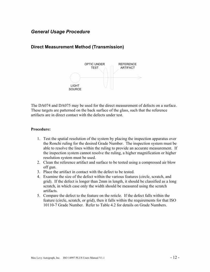
General Usage Procedure
Direct Measurement Method (Transmission)
LIGHT SOURCE
REFERENCEARTIFACT
OPTIC UNDERTEST
The DA074 and DA075 may be used for the direct measurement of defects on a surface. These targets are patterned on the back surface of the glass, such that the reference artifacts are in direct contact with the defects under test. Procedure:
1. Test the spatial resolution of the system by placing the inspection apparatus over the Ronchi ruling for the desired Grade Number. The inspection system must be able to resolve the lines within the ruling to provide an accurate measurement. If the inspection system cannot resolve the ruling, a higher magnification or higher resolution system must be used.
2. Clean the reference artifact and surface to be tested using a compressed air blow off gun.
3. Place the artifact in contact with the defect to be tested. 4. Examine the size of the defect within the various features (circle, scratch, and
grid). If the defect is longer than 2mm in length, it should be classified as a long scratch, in which case only the width should be measured using the scratch artifacts.
5. Compare the defect to the feature on the reticle. If the defect falls within the feature (circle, scratch, or grid), then it falls within the requirements for that ISO 10110-7 Grade Number. Refer to Table 4.2 for details on Grade Numbers.

Max Levy Autograph, Inc. ISO 14997 PLUS Users Manual V1.1 - 13 -
Method for Viewing in Reflection
OPTIC UNDERTEST
LIGHT SOURCE
REFERENCEARTIFACT
BEAM SPLITTER
ISO 14997 defines a test method for part inspection in reflection. The DA078 artifact is ideally suited to this type of measurement. Full details on this test method are available in ISO 14997(2003) Figure 1b, Page 4. The reflective method requires that the pattern have negative polarity (clear features on an opaque background). Using a beam splitter, light source, and reflecting mirror, the DA078 reference artifact may be placed in front of a reflecting mirror such that the light passing through the clear features of the reference passes through a beam splitter and through to the observer.
Method of Classification Standard Defects ISO 10110-7 classifies all types of defects according to the surface area they obscure. All defects, regardless of their shape, fall into a size classification. The exception is for long scratches, defined as a thin imperfection longer than 2mm in length. Although the drawing conventions do not differentiate between circular defects and scratches, the reference standard proposed by ISO 10110-7 does provide separate features for these two defects. This differentiation expedites the classification process; instead of having to measure all sides of a defect and calculate the surface area, the user can simply compare the defect to a comparable artifact on the reference standard. Long Scratches
Max Levy Autograph, Inc. ISO 14997 PLUS Users Manual V1.1 - 14 -
In the case of long scratches, these are identified only by their width. In identifying long scratches, it is only necessary to compare the width of the long scratch to the width of a scratch on the reference standard. For future reference, the length of the scratch may be measured with the linear scale. Coating Blemishes Coating blemishes principly concern optical coatings on elements. These coatings may be Anti-Reflective (AR), bandpass, neutral density, masks, and other types of coatings applied to an optical surface. Delineated patterns fall into this classification as well. If no indication is specified for coating blemishes, then the coating is to be inspected according to the standard surface imperfection tolerances. Coating Blemishes are classified in a similar manner to standard surface imperfections such as scratches and digs. However, these imperfections may be toleranced separately by precedirng the specification with the code “C.” A full explanation is available in Table 4.1. Edge Chips An edge chip is any type of defect that extends from the edge of an optical surface. Edge chips are usually caused by the manufacturing process or from improper handling. Edge chips are classified independently of the other types of surface imperfections. Edge chips are not classified according to surface area as the rest of ISO 10110-7 features are. Instead, only the extent of the edge chip from the physical edge of the element is measured. This extent is specified in millimeters. Note the measurement must be parallel to the surface of the element and that any number of edge chips are permissible as long as they do not extend past the specified distance from the edge of the optic.
Max Levy Autograph, Inc. ISO 14997 PLUS Users Manual V1.1 - 15 -
4. Conventions of the Standard
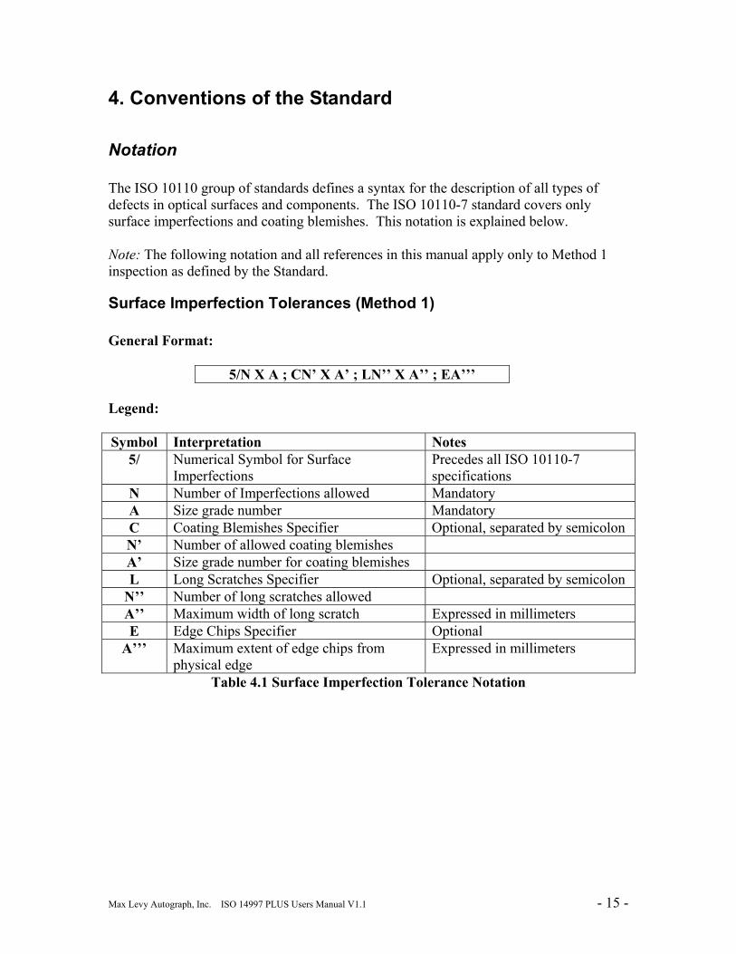
Notation The ISO 10110 group of standards defines a syntax for the description of all types of defects in optical surfaces and components. The ISO 10110-7 standard covers only surface imperfections and coating blemishes. This notation is explained below. Note: The following notation and all references in this manual apply only to Method 1 inspection as defined by the Standard.
Surface Imperfection Tolerances (Method 1) General Format:
5/N X A ; CN’ X A’ ; LN’’ X A’’ ; EA’’’ Legend: Symbol Interpretation Notes
5/ Numerical Symbol for Surface Imperfections
Precedes all ISO 10110-7 specifications
N Number of Imperfections allowed Mandatory A Size grade number Mandatory C Coating Blemishes Specifier Optional, separated by semicolon N’ Number of allowed coating blemishes A’ Size grade number for coating blemishes L Long Scratches Specifier Optional, separated by semicolon
N’’ Number of long scratches allowed A’’ Maximum width of long scratch Expressed in millimeters E Edge Chips Specifier Optional
A’’’ Maximum extent of edge chips from physical edge
Expressed in millimeters
Table 4.1 Surface Imperfection Tolerance Notation
Max Levy Autograph, Inc. ISO 14997 PLUS Users Manual V1.1 - 16 -
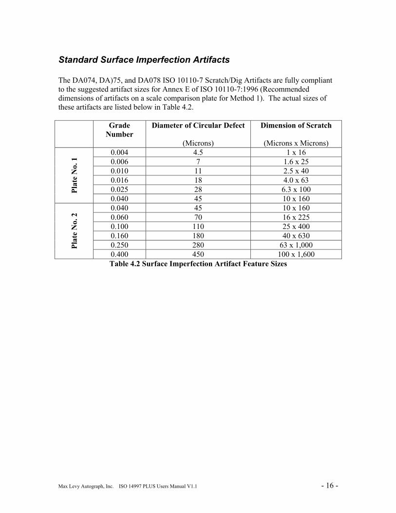
Standard Surface Imperfection Artifacts The DA074, DA)75, and DA078 ISO 10110-7 Scratch/Dig Artifacts are fully compliant to the suggested artifact sizes for Annex E of ISO 10110-7:1996 (Recommended dimensions of artifacts on a scale comparison plate for Method 1). The actual sizes of these artifacts are listed below in Table 4.2. Grade
Number Diameter of Circular Defect
(Microns)
Dimension of Scratch
(Microns x Microns) 0.004 4.5 1 x 16 0.006 7 1.6 x 25 0.010 11 2.5 x 40 0.016 18 4.0 x 63 0.025 28 6.3 x 100 Pl
ate
No.
1
0.040 45 10 x 160 0.040 45 10 x 160 0.060 70 16 x 225 0.100 110 25 x 400 0.160 180 40 x 630 0.250 280 63 x 1,000 Pl
ate
No.
2
0.400 450 100 x 1,600 Table 4.2 Surface Imperfection Artifact Feature Sizes
Max Levy Autograph, Inc. ISO 14997 PLUS Users Manual V1.1 - 17 -
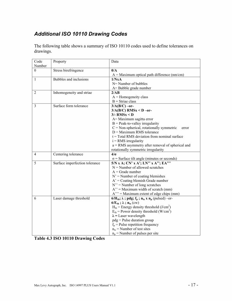
Additional ISO 10110 Drawing Codes The following table shows a summary of ISO 10110 codes used to define tolerances on drawings. Code Number
Property Data
0 Stress birefringence 0/A A = Maximum optical path difference (nm/cm)
1 Bubbles and inclusions 1/NxA N= Number of bubbles A= Bubble grade number
2 Inhomogeneity and striae 2/AB A = Homogeneity class B = Striae class
3 Surface form tolerance 3/A(B/C) –or- 3/A(B/C) RMSx < D –or- 3/- RMSx < D A= Maximum sagitta error B = Peak-to-valley irregularity C = Non-spherical, rotationally symmetric error D = Maximum RMS tolerance t = Total RMS deviation from nominal surface i = RMS irregularity a = RMS asymmetry after removal of spherical and rotationally symmetric irregularity
4 Centering tolerance 4/σ σ = Surface tilt angle (minutes or seconds)
5 Surface imperfection tolerance 5/N x A; CN’ x A’; LN’’ x A’’; EA’’’ N = Number of allowed scratches A = Grade number N’ = Number of coating blemishes A’ = Coating blemish Grade number N’’ = Number of long scratches A’’ = Maximum width of scratch (mm) A’’’ = Maximum extent of edge chips (mm)
6 Laser damage threshold 6/Hth; λ ; pdg; fp ; nts x np (pulsed) –or- 6/Eth ; λ ; nts (cw) Hth = Energy density threshold (J/cm2) Eth = Power density threshold (W/cm2) λ = Laser wavelength pdg = Pulse duration group fp = Pulse repetition frequency nts = Number of test sites np = Number of pulses per site
Table 4.3 ISO 10110 Drawing Codes
Max Levy Autograph, Inc. ISO 14997 PLUS Users Manual V1.1 - 18 -
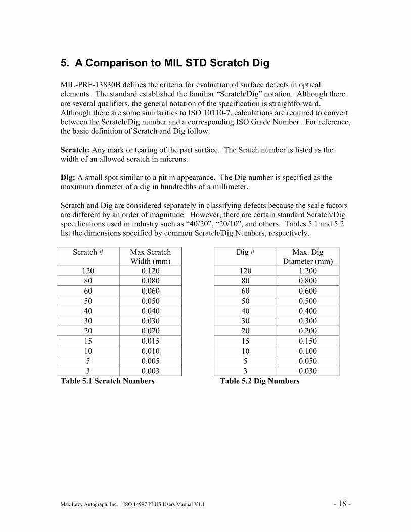
5. A Comparison to MIL STD Scratch Dig MIL-PRF-13830B defines the criteria for evaluation of surface defects in optical elements. The standard established the familiar “Scratch/Dig” notation. Although there are several qualifiers, the general notation of the specification is straightforward. Although there are some similarities to ISO 10110-7, calculations are required to convert between the Scratch/Dig number and a corresponding ISO Grade Number. For reference, the basic definition of Scratch and Dig follow. Scratch: Any mark or tearing of the part surface. The Sratch number is listed as the width of an allowed scratch in microns. Dig: A small spot similar to a pit in appearance. The Dig number is specified as the maximum diameter of a dig in hundredths of a millimeter. Scratch and Dig are considered separately in classifying defects because the scale factors are different by an order of magnitude. However, there are certain standard Scratch/Dig specifications used in industry such as “40/20”, “20/10”, and others. Tables 5.1 and 5.2 list the dimensions specified by common Scratch/Dig Numbers, respectively.
Scratch # Max Scratch Width (mm)
120 0.120 80 0.080 60 0.060 50 0.050 40 0.040 30 0.030 20 0.020 15 0.015 10 0.010 5 0.005 3 0.003
Dig # Max. Dig Diameter (mm)
120 1.200 80 0.800 60 0.600 50 0.500 40 0.400 30 0.300 20 0.200 15 0.150 10 0.100 5 0.050 3 0.030
Table 5.1 Scratch Numbers Table 5.2 Dig Numbers
Max Levy Autograph, Inc. ISO 14997 PLUS Users Manual V1.1 - 19 -
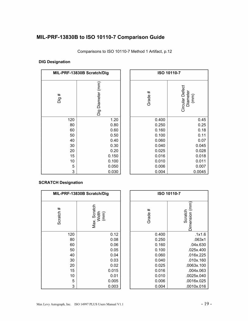
MIL-PRF-13830B to ISO 10110-7 Comparison Guide
Comparisons to ISO 10110-7 Method 1 Artifact, p.12 DIG Designation MIL-PRF-13830B Scratch/Dig ISO 10110-7
Dig
#
Dig
Dia
met
er (m
m)
Gra
de #
Circ
ular
Def
ect
Dia
met
er
(mm
)
120 1.20 0.400 0.45 80 0.80 0.250 0.25 60 0.60 0.160 0.18 50 0.50 0.100 0.11 40 0.40 0.060 0.07 30 0.30 0.040 0.045 20 0.20 0.025 0.028 15 0.150 0.016 0.018 10 0.100 0.010 0.011 5 0.050 0.006 0.007 3 0.030 0.004 0.0045 SCRATCH Designation MIL-PRF-13830B Scratch/Dig ISO 10110-7
Scr
atch
#
Max
. Scr
atch
W
idth
(m
m)
Gra
de #
Scr
atch
D
imen
sion
(mm
)
120 0.12 0.400 .1x1.6 80 0.08 0.250 .063x1 60 0.06 0.160 .04x.630 50 0.05 0.100 .025x.400 40 0.04 0.060 .016x.225 30 0.03 0.040 .010x.160 20 0.02 0.025 .0063x.100 15 0.015 0.016 .004x.063 10 0.01 0.010 .0025x.040 5 0.005 0.006 .0016x.025 3 0.003 0.004 .0010x.016
Max Levy Autograph, Inc. ISO 14997 PLUS Users Manual V1.1 - 20 -
The MLA catalog features a full selection of optical testing and dimensional calibration artifacts.
Visit us online at
www.maxlevy.com