ISM500/501/502-CV Series Interceptor Switch Module Instructions/ISM/ISM50X-CV 080317.pdf · The ISM...
5
InterMotive Inc. 12840 Earhart Ave. Auburn, CA 95602 Phone: (530) 823-1048 Fax: (530) 823-1516 Page 1 of 5 www.intermotive.net [email protected] ISM50X-CV-080317-INS An ISO 9001:2008 Registered Company ISM500/501/502-CV Series Interceptor Switch Module 2013 - 2016 Ford Police Interceptor Sedan 2013 - 2015 Ford Police Interceptor Utility Introduction The Ford Police Interceptors (Sedan and SUV) offer four switches marked ‘Seek’ and ‘Volume’ on the right-side of the steering wheel. From the factory, the switches control the Seek and Volume functions for the OEM radio. The Intermotive ISM50x-BV gives the Police market the ability to program each switch/output. The ISM allows each switch and associated output to be programmed in the following operating modes: • Latching (toggle on—toggle off) • Momentary • Timed (1 - 1,800 seconds) • Radio Button (only one Radio Button active at a time) Example: Seek Up (Aux 1), Seek Down (Aux 2), and Vol Up (Aux 3) programmed as Code 1-3 “Radio Buttons”. Their outputs are wired to appropriate lights/sirens, etc. Pushing any of these three rocker switches activates the desired Code and shuts the others off such that only one is active at a time. Vol Down (Aux 4) could be programmed as Latching, Momentary, or Timed, independent of Aux 1-3. Installation Instructions Disconnect vehicle battery before proceeding with installation. IMPORTANT—READ BEFORE INSTALLATION It is the installer’s responsibility to route and secure all wiring harnesses where they cannot be damaged by sharp objects, mechanical moving parts and high heat sources. Failure to do so could result in damage to the system or vehicle and create possible safety concerns for the operator and passengers. Avoid placing the module where it could encounter strong magnetic fields from high current cabling connected to motors, solenoids, etc. Avoid radio frequency energy from antennas or inverters next to the module. Avoid high voltage spikes in vehicle wiring by always using diode clamped relays when installing upfitter circuits.
Transcript of ISM500/501/502-CV Series Interceptor Switch Module Instructions/ISM/ISM50X-CV 080317.pdf · The ISM...

InterMotive Inc.
12840 Earhart Ave. Auburn, CA 95602
Phone: (530) 823-1048
Fax: (530) 823-1516 Page 1 of 5
www.intermotive.net
[email protected] ISM50X-CV-080317-INS
An ISO 9001:2008 Registered Company
ISM500/501/502-CV Series Interceptor Switch Module
2013 - 2016 Ford Police Interceptor Sedan 2013 - 2015 Ford Police Interceptor Utility
Introduction
The Ford Police Interceptors (Sedan and SUV) offer four switches marked ‘Seek’ and ‘Volume’ on the right-side of the steering wheel. From the factory, the switches control the Seek and Volume functions for the OEM radio. The Intermotive ISM50x-BV gives the Police market the ability to program each switch/output. The ISM allows each switch and associated output to be programmed in the following operating modes:
• Latching (toggle on—toggle off)
• Momentary
• Timed (1 - 1,800 seconds)
• Radio Button (only one Radio Button active at a time)
Example: Seek Up (Aux 1), Seek Down (Aux 2), and Vol Up (Aux 3) programmed as Code 1-3 “Radio Buttons”. Their outputs are wired to appropriate lights/sirens, etc. Pushing any of these three rocker switches activates the desired Code and shuts the others off such that only one is active at a time. Vol Down (Aux 4) could be programmed as Latching, Momentary, or Timed, independent of Aux 1-3.
Installation Instructions
Disconnect vehicle battery before proceeding with installation.
IMPORTANT—READ BEFORE INSTALLATION
It is the installer’s responsibility to route and secure all wiring harnesses where they cannot be damaged by sharp objects, mechanical moving parts and high heat sources. Failure to do so could result in damage
to the system or vehicle and create possible safety concerns for the operator and passengers. Avoid placing the module where it could encounter strong magnetic fields from high current cabling connected to motors, solenoids, etc. Avoid radio frequency energy from antennas or inverters next to the module. Avoid high voltage spikes in vehicle wiring by always using diode clamped relays when
installing upfitter circuits.
InterMotive Inc.
12840 Earhart Ave. Auburn, CA 95602
Phone: (530) 823-1048
Fax: (530) 823-1516 Page 2 of 5
www.intermotive.net
[email protected] ISM50X-CV-080317-INS
Installation Instructions (continued)
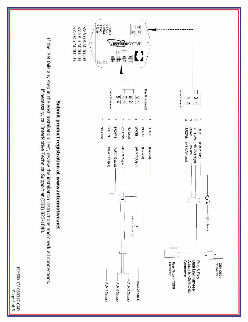
Data Link Harness Installation
1. Locate the vehicle’s OBDII Data Link Connector, mounted below the lower left dash panel.
2. Remove the mounting screws for the OBDII connector. Plug the red connector from the ISM Data Link Harness into the vehicle’s OBDII connector. Ensure the connection is fully seated and secure with the supplied wire tie.
3. Mount the Black pass through connector from the ISM Data Link Harness in the former location of the vehicle’s OBDII connector.
4. Secure the ISM Data Link harness so that it does not hang below the lower dash panel.
5. Attach the Red wire (with factory installed 3-amp fuse) to a Hot in Run power source
6. Plug the free end of the Data Link harness into the mating 4-pin
connector on the ISM module.
Output Harness Installation
1. Attach the Black wire eyelet to a known good ground point.
2. Route the 4 Aux. Output Wires (Green, Brown, Yellow, and White) under the center console and connect them to the desired equipment. These outputs are active low, providing 1/2A ground circuits when the respective switch is active.
3. Plug the connector into the mating 8-pin connector on the ISM module.
InterMotive Inc.
12840 Earhart Ave. Auburn, CA 95602
Phone: (530) 823-1048
Fax: (530) 823-1516 Page 3 of 5
www.intermotive.net
[email protected] ISM50X-CV-080317-INS
Installation Instructions (continued)
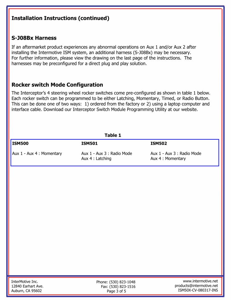
Rocker switch Mode Configuration
The Interceptor’s 4 steering wheel rocker switches come pre-configured as shown in table 1 below. Each rocker switch can be programmed to be either Latching, Momentary, Timed, or Radio Button. This can be done one of two ways: 1) ordered from the factory or 2) using a laptop computer and interface cable. Download our Interceptor Switch Module Programming Utility at our website.
ISM500 Aux 1 - Aux 4 : Momentary
ISM501 Aux 1 - Aux 3 : Radio Mode Aux 4 : Latching
ISM502 Aux 1 - Aux 3 : Radio Mode Aux 4 : Momentary
Table 1
S-J08Bx Harness
If an aftermarket product experiences any abnormal operations on Aux 1 and/or Aux 2 after installing the Intermotive ISM system, an additional harness (S-J08Bx) may be necessary. For further information, please view the drawing on the last page of the instructions. The harnesses may be preconfigured for a direct plug and play solution.
Submit p
roduct re
gistration at w
ww.intermotive.net
If the IS
M fa
ils any ste
p in
the Post In
stallatio
n Test, re
view th
e in
stallatio
n in
structio
ns a
nd ch
eck all co
nnectio
ns.
If necessa
ry, ca
ll InterM
otive Technica
l Support a
t (530) 8
23-1048.
ISM50X-CV-080317-CAD
Page 4 of 5

Submit p
roduct re
gistration at w
ww.intermotive.net
If the IS
M fa
ils any ste
p in
the Post In
stallatio
n Test, re
view th
e in
stallatio
n in
structio
ns a
nd ch
eck all co
nnectio
ns.
If necessa
ry, ca
ll InterM
otive Technica
l Support a
t (530) 8
23-1048.
ISM50X-CV-080317-CAD
Page 5 of 5
S-J08Bx Harness


![Ampnetconnect catalog [080317]](https://static.fdocuments.us/doc/165x107/568c361f1a28ab023596dc49/ampnetconnect-catalog-080317.jpg)