ISL Training Manual - websites.pmc.ucsc.edusilab/ThermoManuals... · This ISL Training Manual is...
142
Part of Thermo Fisher Scientific Thermo Fisher Scientific ISL Training Manual Revision A - 1250890
Transcript of ISL Training Manual - websites.pmc.ucsc.edusilab/ThermoManuals... · This ISL Training Manual is...

Part of Thermo Fisher Scientific
Thermo Fisher Scientific
ISLTraining Manual
Revision A - 1250890

© 2009 Thermo Fisher Scientific Inc. All rights reserved.
All trademarks are the property of Thermo Fisher Scientific Inc. and its subsidiaries.
Thermo Fisher Scientific Inc. provides this document to its customers with a product purchase to use in the product operation. This document is copyright protected and any reproduction of the whole or any part of this document is strictly prohibited, except with the written authorization of Thermo Fisher Scientific Inc.
The contents of this document are subject to change without notice. All technical information in this document is for reference purposes only. System configurations and specifications in this document supersede all previous information received by the purchaser.
Thermo Fisher Scientific Inc. makes no representations that this document is complete, accurate or error-free and assumes no responsibility and will not be liable for any errors, omissions, damage or loss that might result from any use of this document, even if the information in the document is followed properly.
This document is not part of any sales contract between Thermo Fisher Scientific Inc. and a purchaser. This document shall in no way govern or modify any Terms and Conditions of Sale, which Terms and Conditions of Sale shall govern all conflicting information between the two documents.
Revision History: Revision A released in January 2010.

United States
Fax.........+1 561 688 8731E-mail [email protected]
Canada
2845 Argentia Road, Unit 4Mississauga, OntarioL5N 8G6Phone ....+1 800 530 8447Fax.........+1 905 890 5775E-mail [email protected]
Europe
Austria
Wehlistrasse 27b 1200 WienPhone ....+43 1 333 50340Fax.........+43 1 333 503426E-mail [email protected]
Belgium
Z3 Doornveld 1721731 ZellikPhone ....+32 2 482 30 30Fax.........+32 2 482 30 31E-mail [email protected]
Denmark
Fruebjergvej 3 2100 KøbenhavnPhone ....+45 2 70 23 62 60Fax.........+45 2 70 23 62 63E-mail [email protected]
France
(also representing French speaking N. Africa, Algeria, Morocco, and Tunisia)
16 Avenue du Québec Silic 765 Z.A. de Courtaboeuf 91963 Les Ulis Cédex, France Phone ....+33 1 60 92 48 00Fax.........+33 1 60 92 49 00E-mail [email protected]
Germany
Im Steingrund 4–6 63303 Dreieich, GermanyPhone.... +49 6103 408 1050Fax ........ +49 6103 408 1213E-mail ... [email protected]
Italy
Strada Rivoltana 20090 Rodano (Milano)Phone....Numero Verde 800823162Fax ........+39 2 950 59 225
Netherlands
Takkebijsters 1 4817 BL Breda, Netherlands NederlandPhone.... +31 76 579 55 55Fax ........ +31 76 571 41 71E-mail ... [email protected]
Spain
Valportillo I, 22 1a Planta, Edificio CaobaES-28108 Alcobendas (Madrid)Phone.... +34 914 845 965Fax ........ +34 914 843 598E-mail ... [email protected]
Spain
Acer 30-32Edificio Sertram – Planta 2, Modulo 3ES-08038 (Barcelona)Phone.... +34 93 223 0918Fax ........ +34 93 223 0982E-mail ... [email protected]
Sweden, Norway, and Finland
Pyramidbacken 3SE-141 75 Kungens Kurva (Stockholm)Phone.... +46 8 556 468 00Fax ........ +46 8 556 468 08E-mail ... [email protected]
Switzerland
Neuhofstrasse 114153 ReinachPhone.... +41 61716 77 00Fax ........ +41 61716 77 20E-mail ... [email protected]
Offices for Thermo Scientific Products

Europe - Continued
United Kingdom
Stafford House1 Boundary ParkBoundary WayHemel HempsteadHertfordshire HP2 7GEPhone ....+44 1442 233 555Fax.........+44 1442 233 667E-mail [email protected]
Other Europe, Middle East, and Africa
Wehlistrasse 27bA-1200 WienPhone ....+43 1 333 50 34 0Fax.........+43 1 333 50 34 26E-mail [email protected]
Australia and Asia
Australia
P.O. Box 239 RydalmereUnit 14, 38 - 46 South StreetRydalmere, N.S.W. 2116Phone.... +61 2 8844 9500Fax ........ +61 2 8844 9599E-mail ... [email protected]
Japan
C-2F 3-9 Moriya-cho, Kanagawa-kuYokohama, Kanagawa 221-0022Phone.... +81 45 453 9197Fax ........ +81 45 453 9235E-mail ... [email protected]
Japan
6F, Ryokuchi-eki Building2-4-1 Terauchi, Toyonaka CityOsaka 561-0872Phone.... +81 6 6863-1551Fax ........ +81 6 6863-1096E-mail ... [email protected]
P.R. China
Rm. 702-715, 7F Tower West, Younghe PlazaNo. 28, Andingmen East StreetBeijing 100007Phone.... 800 810 5118, 400 650 5118 (Free lines)Fax ........ +86 10 88370548E-mail ... [email protected]
P.R. China
Building 6No. 27 Xin Jin Qiao RoadShanghai 201206mPhone.... 800 810 5118, 400 650 5118 (Free lines)Fax ........ +86 21 64457830E-mail ... [email protected]
Offices for Thermo Scientific Products - Continued

Read This First
Welcome to the Thermo Scientific ISL Training Manual! The Thermo Fisher Scientific Isodat script language (ISL) is part of the Isodat software package for the Thermo Scientific family of gas isotope ratio mass spectrometers (IRMS).
About This GuideThe purpose of this ISL Training Manual is to provide users with specific information regarding the Thermo Fisher Scientific Isodat script language (ISL). Read each section carefully.
Who Uses This Guide
This ISL Training Manual is intended primarily for advanced users of the Thermo Fisher Scientific Isodat software package.
Scope of This Guide
The ISL Training Manual includes the following chapters:
• Chapter 1: “Introduction to Thermo Fisher Scientific ISL” gives a short introduction to the Isodat script language (ISL).
• Chapter 2: “Device Editor” explains how to configure your device with the Device Editor.
• Chapter 3: “Panel Designer”describes how to create the visualization for your device.
• Chapter 4: “ISL Programming” covers general information about libraries, functions and variables. You learn to write and edit scripts.
• The Chapter 5: “Repetition” revises the steps learned in the previous chapters.
Thermo Fisher Scientific ISL Training Manual i

Read This FirstRelated Documentation
Related DocumentationIn addition to this manual, Thermo Fisher Scientific provides the following documents about Isodat:
• Operating Manuals of your Delta V Series and MAT 253
• Operating Manuals of their peripherals
ii ISL Training Manual Thermo Fisher Scientific
Read This FirstContacting Us
Contacting UsThere are several ways to contact Thermo Fisher Scientific.
Assistance
For technical support and ordering information, visit us on the Web:
www.thermo.com/advancedms
Customer Information Service
cis.thermo-bremen.com is the Customer Information Service site aimed at providing instant access to
• latest software updates
• manuals, application reports, and brochures.
Note Thermo Fisher Scientific recommends that you register with the site as early as possible. ▲
To register, visit register.thermo-bremen.com/form/cis and fill in the registration form. Once your registration has been finalized, you will receive confirmation by e-mail.
Changes to the Manual
❖ To suggest changes to this manual• Please send your comments (in German or English) to:
Editors, Technical Documentation Thermo Fisher Scientific (Bremen) GmbH Hanna-Kunath-Str. 11
28199 Bremen
Germany• Send an e-mail message to the Technical Editor at
You are encouraged to report errors or omissions in the text or index. Thank you.
Thermo Fisher Scientific ISL Training Manual iii
Read This FirstTypographical Conventions
Typographical ConventionsThis section describes typographical conventions that have been established for Thermo Fisher Scientific manuals.
Data Input
Throughout this manual, the following conventions indicate data input and output via the computer:
• Messages displayed on the screen are represented by capitalizing the initial letter of each word and by italicizing each word.
• Input that you enter by keyboard is identified by quotation marks: single quotes for single characters, double quotes for strings.
• For brevity, expressions such as “choose File > Directories” are used rather than “pull down the File menu and choose Directories.”
• Any command enclosed in angle brackets < > represents a single keystroke. For example, “press <F1>” means press the key labeled F1.
• Any command that requires pressing two or more keys simultaneously is shown with a plus sign connecting the keys. For example, “press <Shift> + <F1>” means press and hold the <Shift> key and then press the <F1> key.
• Any button that you click on the screen is represented in bold face letters. For example, “click on Close”.
Topic Headings
The following headings are used to show the organization of topics within a chapter:
Chapter 1 Chapter Name
Second Level Topics
Third Level Topics
Fourth Level Topics
iv ISL Training Manual Thermo Fisher Scientific
Read This FirstSafety and EMC Information
Safety and EMC InformationIn accordance with our commitment to customer service and safety, this instrument has satisfied the requirements for the European CE Mark including the Low Voltage Directive.
Designed, manufactured and tested in an ISO9001 registered facility, this instrument has been shipped to you from our manufacturing facility in a safe condition.
This instrument must be used as described in this manual. Any use of this instrument in a manner other than described here may result in instrument damage and/or operator injury.
Notice on Lifting and Handling of Thermo Scientific Instruments
For your safety, and in compliance with international regulations, the physical handling of this Thermo Scientific instrument requires a team effort for lifting and/or moving the instrument. This instrument is too heavy and/or bulky for one person alone to handle safely.
Notice on the Proper Use of Thermo Scientific Instruments
In compliance with international regulations: If this instrument is used in a manner not specified by Thermo Fisher Scientific, the protection provided by the instrument could be impaired.
Notice on the Susceptibility to Electromagnetic Transmissions
Your instrument is designed to work in a controlled electromagnetic environment. Do not use radio frequency transmitters, such as mobile phones, in close proximity to the instrument.
Safety and Special Notices
Make sure you follow the precautionary statements presented in this guide. The safety and other special notices appear different from the main flow of text. Safety and special notices include the following:
Caution Cautions highlight information necessary to protect your instrument from damage. ▲
Note Notes highlight information that can affect the quality of your data. In addition, notes often contain information that you might need if you are having trouble. ▲
Warning Warnings highlight hazards to human beings. Each Warning is accompanied by a Warning symbol. ▲
Thermo Fisher Scientific ISL Training Manual v

Read This FirstSafety and EMC Information
Identifying Safety Information
This guide contains precautionary statements that can prevent personal injury, instrument damage, and loss of data if properly followed. Warning symbols alert the user to check for hazardous conditions. These appear throughout the manual, where applicable. The most common warning symbols are:
Warning General Hazard. This general symbol indicates that a hazard is present that could result in injuries if it is not avoided. The source of danger is described in the accompanying text. ▲
Warning Electric Shock Hazard. High Voltages capable of causing personal injury are used in the instrument. The instrument must be shut down and disconnected from line power before service is performed. Do not operate the instrument with the top cover off. Do not remove protective covers from PCBs. ▲
Warning Strong Magnetic Field. Strong magnetic fields are used in the instrument. Keep away from heart pacemakers, computers, credit cards, and any other magnetically sensitive device. Do not bring compressed gas cylinders within close proximity to the instrument. ▲
Warning Burn Hazard. Treat heated zones with respect. Parts of the instrument might be very hot and might cause severe burns if touched. Allow hot components to cool before servicing them. ▲
Warning Frostbite Hazard. Careless handling of cryogenic liquids might cause severe personal injury including frostbite. Wear protective clothing when operating this equipment including insulated gloves and face shield. ▲
Warning Corrosive Matrerial. Wear gloves when handling toxic, carcinogenic, mutagenic, or corrosive/irritant chemicals. Use approved containers and procedures for disposal of waste solution. ▲
Warning Laser Radiation. Avoid eye or skin exposure to direct or scattered radiation! ▲
vi ISL Training Manual Thermo Fisher Scientific

Read This FirstSafety and EMC Information
In addition to the above described, every instrument has specific hazards. So, be sure to read and comply with the precautions described in the subsequent chapters of this guide. They will help ensure the safe, long-term use of your system.
General Safety Precautions
Observe the following safety precautions when you operate or perform service on your instrument:
• Before plugging in any of the instrument modules or turning on the power, always make sure that the voltage and fuses are set appropriately for your local line voltage.
• Only use fuses of the type and current rating specified. Do not use repaired fuses and do not short-circuit the fuse holder.
• The supplied power cord must be inserted into a power outlet with a protective earth contact (ground). When using an extension cord, make sure that the cord also has an earth contact.
• Do not change the external or internal grounding connections. Tampering with or disconnecting these connections could endanger you and/or damage the system.
• The instrument is properly grounded in accordance with regulations when shipped. You do not need to make any changes to the electrical connections or to the instrument’s chassis to ensure safe operation.
• Never run the system without the housing on. Permanent damage can occur.
• Do not turn the instrument on if you suspect that it has incurred any kind of electrical damage. Instead, disconnect the power cord and contact a Service Representative for a product evaluation. Do not attempt to use the instrument until it has been evaluated. (Electrical damage may have occurred if the system shows visible signs of damage, or has been transported under severe stress.)
• Damage can also result if the instrument is stored for prolonged periods under unfavorable conditions (e.g., subjected to heat, water, etc.).
• Always disconnect the power cord before attempting any type of maintenance.
• Capacitors inside the instrument may still be charged even if the instrument is turned off.
Thermo Fisher Scientific ISL Training Manual vii

Read This FirstSafety and EMC Information
• Never try to repair or replace any component of the system that is not described in this manual without the assistance of your service representative.
• Do not place any objects – especially not containers with liquids – upon the instrument. Leaking liquids might get into contact with electronic components and cause a short circuit.
Safety Advice for Possible Contamination
Hazardous Material Might Contaminate Certain Parts of Your System During Analysis.
In order to protect our employees, we ask you to adhere to special precautions when returning parts for exchange or repair.
If hazardous materials have contaminated mass spectrometer parts, Thermo Fisher Scientific can only accept these parts for repair if they have been properly decontaminated. Materials, which due to their structure and the applied concentration might be toxic or which in publications are reported to be toxic, are regarded as hazardous. Materials that will generate synergetic hazardous effects in combination with other present materials are also considered hazardous.
Your signature on the Repair-Covering letter confirms that the returned parts have been decontaminated and are free of hazardous materials.
The Repair-Covering letter can be ordered from your service engineer or downloaded from the Customer Information Service (CIS) site. Please register under http://register.thermo-bremen.com/form/cis.
Parts contaminated by radioisotopes are not subject to return to Thermo Fisher Scientific – either under warranty or the exchange part program. If parts of the system may be possibly contaminated by hazardous material, please make sure the Field engineer is informed before the engineer starts working on the system.
viii ISL Training Manual Thermo Fisher Scientific
Contents
Chapter 1 Introduction to Thermo Fisher Scientific ISL.......................1-1
Chapter 2 Device Editor..............................................................................2-1Creating a New User Device ............................................. 2-2Editing a User Device ....................................................... 2-5
Configuring Device Objects........................................... 2-6Basic Hardware Parameters ......................................... 2-8Interface Type Fiberline .............................................. 2-9Interface Type Gpib.................................................. 2-10Interface Type Comport Extended............................ 2-11
Dio-derived Classes ...................................................... 2-15Adc-derived Classes ...................................................... 2-16
CalculatingAdc.......................................................... 2-18PressureMeter ........................................................... 2-20HV Status ................................................................. 2-21
Dac-derived Classes...................................................... 2-22CalculatingDac ......................................................... 2-23Magnet Current ........................................................ 2-25Basic HV................................................................... 2-25
Configuring Events ...................................................... 2-25Configuring Sequence .................................................. 2-26
SequenceText............................................................ 2-27SequenceFlag ............................................................ 2-28
Configuring Monitor Parameters ................................. 2-29Configuring System Start Values.................................. 2-30
Closing the Device Editor ............................................... 2-32Selecting an Acquisition Mode........................................ 2-33Selecting Interface Modes................................................ 2-35Exporting Isodat Settings to Offline Computers.............. 2-36EXERCISE 1: Create a Device........................................ 2-37
Task ............................................................................. 2-37
Thermo Fisher Scientific ISL Training Manual ix

Contents
Solution ....................................................................... 2-37Defining Hardware Components .............................. 2-38Setting Properties for the Valves................................ 2-38Setting Properties for AdcTemperature ..................... 2-39Defining Events Parameter........................................ 2-40Defining Sequence Parameter ................................... 2-41Defining Monitor Parameters ................................... 2-43Defining System Start Values .................................... 2-43Closing the Device Editor ......................................... 2-44Creating a New Configuration .................................. 2-44Defining an Acquisition Mode.................................. 2-45
Chapter 3 Panel Designer ......................................................................... 3-1Creating a New Panel........................................................ 3-2Creating a Visualization in the Panel................................. 3-4
Visual Object Text ......................................................... 3-4Visual Object Pipe ......................................................... 3-6Visual Object Valve........................................................ 3-9Arrange Visual Objects................................................. 3-11Lock Visual Objects ..................................................... 3-12Group Visual Objects................................................... 3-13
Saving the Visualization .................................................. 3-15Assigning Visualization ................................................... 3-16EXERCISE 2: Create a Visualization .............................. 3-18
Task ............................................................................. 3-18Solution ....................................................................... 3-18
Creating New Panel .................................................. 3-18Defining Visualization of Valves ............................... 3-19Defining Visualization of AdcTemperature ............... 3-20Assigning Names to the Valves.................................. 3-20Connecting the Three Valves and Adc Temperature with Pipes ......................................................................... 3-21Saving the Visualization ............................................ 3-21Assigning a Visualization Dialog ............................... 3-22
Chapter 4 ISL Programming ...................................................................... 4-1The ISL Library Concept .................................................. 4-2Functions .......................................................................... 4-4
Core Functions/Internal ISL Functions.......................... 4-4Overview of Core Functions ....................................... 4-4Inserting Functions ..................................................... 4-5Viewing Function Argument List ................................ 4-6
User-implemented Functions ......................................... 4-6Dynamic Externals ............................................................ 4-7Opening the ISL Edit Mode ............................................. 4-9
ISL Script Types .......................................................... 4-10
x ISL Training Manual Thermo Fisher Scientific

Contents
ISL Script Structure ..................................................... 4-11Commonly Used Symbols in ISL Edit Mode ............... 4-11Color Syntax in ISL ..................................................... 4-12Tools in the ISL Edit Mode ......................................... 4-12
Help.......................................................................... 4-12Context Menu .......................................................... 4-12
Debugging ...................................................................... 4-14Setting Runtime Debugging......................................... 4-14ISL Toolbar Debug Commands................................... 4-15Debug Bar.................................................................... 4-16
Save Script ...................................................................... 4-17EXERCISE 3: Write a Script .......................................... 4-18
Task ............................................................................. 4-18Solution ....................................................................... 4-18
Creating Variable ...................................................... 4-18Writing Script to Check the Variable ........................ 4-19Debugging the script................................................. 4-20
EXERCISE 4: Write Functions....................................... 4-21Task ............................................................................. 4-21Solution ....................................................................... 4-21
EXERCISE 5: Read Entries in a Sequence ...................... 4-23Task ............................................................................. 4-23
EXERCISE 6: Create Parameters for Methods ................ 4-24Task ............................................................................. 4-24
EXERCISE 7: Declaration of Dynamic Externals, Call Dialog and Evaluation..................................................... 4-25
Task ............................................................................. 4-25
Chapter 5 Repetition ...................................................................................5-1Task .................................................................................. 5-2Creating a New Device ..................................................... 5-2
Configuring the New Device ......................................... 5-3Configuring Events ..................................................... 5-3Configuring Sequence ................................................. 5-4Configuring System Start Values................................. 5-6
Selecting Acqusition Mode................................................ 5-7Creating a New Panel..................................................... 5-8
Creating the Visualization in the New Panel ..................... 5-9Saving the Visualization ............................................... 5-10Assigning a Visualization Dialog .................................. 5-10
Writing the Scripts.......................................................... 5-12Creating the Close Script ............................................. 5-12
Saving the Close Script.............................................. 5-12Creating the Left Script................................................ 5-13
Saving the Left Script ................................................ 5-13Creating the Right Script ............................................. 5-13
Saving the Right Script.............................................. 5-14Assigning the Scripts to the Valves .................................. 5-15
Thermo Fisher Scientific ISL Training Manual xi

Contents
Testing the Scripts .......................................................... 5-17
Glossary ................................................................................... G-1
xii ISL Training Manual Thermo Fisher Scientific

Figures
Isodat subordinate object classes ............................................................ 1-1Isodat folder .......................................................................................... 2-2IsoConfigurator menu Edit ................................................................... 2-2Change into Advanced Mode dialog box ............................................... 2-3Change to Device view in the IsoConfigurator window ........................ 2-3Predefined Devices view ........................................................................ 2-4Add a new User Device ......................................................................... 2-4Rename the User Device ....................................................................... 2-4Right-click menu for device .................................................................. 2-5The tab Device in the Edit window for My Device ............................... 2-6Device tab for My Device with Edit Mode activated ............................. 2-6 Drag and drop Device objects .............................................................. 2-7Right-click menu for a hardware object ................................................. 2-7Interface Type list in hardware parameter dialog ................................... 2-8Basic hardware parameter dialog ........................................................... 2-8Open Interface Type FinniganInterface parameter dialog ...................... 2-9FinniganInterface parameter dialog ..................................................... 2-10Open Interface Type GpibInterface parameter dialog .......................... 2-11GpibInterface parameter dialog ........................................................... 2-11Open Interface Type ComportExtInterface parameter dialog .............. 2-11ComportExtInterface parameter dialog ............................................... 2-12Commands for Send Object and ReceiveObject .................................. 2-13DataSendReceiveText dialog ............................................................... 2-13DataSendReceiveBinary dialog ............................................................ 2-14Number Type list ................................................................................ 2-14Dio-derived classes .............................................................................. 2-15Dio object hardware parameter dialog ................................................. 2-16Adc-derived classes .............................................................................. 2-17AdcHardwarePart parameter dialog ..................................................... 2-18CalculatingAdc .................................................................................... 2-19CalculatingAdc parameter dialog ......................................................... 2-19PressureMeter ..................................................................................... 2-20PressureMeter dialog ........................................................................... 2-21PressureMeter user defined vacuum gauges ......................................... 2-21Dac-derived classes .............................................................................. 2-22Dac object hardware parameter dialog ................................................. 2-23CalculatingDac ................................................................................... 2-24CalculatingDac parameter dialog ........................................................ 2-24The tab Events in the Edit window for My Device .............................. 2-26The tab Sequence in the Edit window for My Device ......................... 2-26Proposals for SequenceText in the tab Sequence ................................. 2-27Right-click menu for SequenceText .................................................... 2-27Properties for SequenceText ................................................................ 2-28
Thermo Fisher Scientific ISL Training Manual xiii

Figures
Right-click menu for SequenceFlag ..................................................... 2-28Properties for SequenceFlag ................................................................. 2-29The tab Monitor Parameter in the DeviceEditor ................................. 2-30The tab System Start Values in the Device Editor ............................... 2-30Properties for valve object of System Start Values ................................ 2-31Closing the Device Editor ................................................................... 2-32Right-click menu of Isodat Configuration.iso ...................................... 2-33New Configuration added to Configurations ...................................... 2-33Right-click menu New Configuration in the IsoConfigurator ............. 2-34Properties of New Configuration ........................................................ 2-34Interface menu in the IsoConfigurator ................................................ 2-35File menu in the IsoConfigurator ........................................................ 2-36The tab Devices for EXERCISE 1 ....................................................... 2-38Properties of Valve 1 for EXERCISE 1 ................................................ 2-38FinniganInterface parameter dialog for EXERCISE 1 ......................... 2-39Properties of AdcTemperature for EXERCISE 1 ................................. 2-40Basic Address setting for AdcTemperature in EXERCISE 1 ................ 2-40The tab Events in the Edit window for EXERCISE 1 ......................... 2-41The tab Sequence and a SequenceText properties ................................ 2-42The tab Sequence and item State ......................................................... 2-42The tab Sequence and item Doit ......................................................... 2-43Defining Monitoring Parameter for ADC ........................................... 2-43Properties for Valve 1 in System Start Values tab ................................ 2-44Add My new device to New Configuration ......................................... 2-45Right-click menu of New Configuration for My new device ............... 2-45Configuration window for acquisition mode ....................................... 2-45New File in Isodat Workspace ............................................................... 3-2PeripheralVisualisation editor with empty panel .................................... 3-3PeripheralVisualisation editor with items in the panel ........................... 3-4Right-click menu of Visual Object Text ................................................ 3-5Properties of Visual Object Text ........................................................... 3-5List for Border of Visual Object Text Properties .................................... 3-6Text in the panel of Visual Object Text Properties ................................ 3-6Properties of Visual Object Pipe ............................................................ 3-7Changing position of Visual Object Pipe by drag and drop ................... 3-7Changing size of Visual Object Pipe box ............................................... 3-8Changing size of pipe ............................................................................ 3-8Changed orientation of pipe .................................................................. 3-8Right-click menu for size handles of pipe .............................................. 3-9Valves dropped into panel ..................................................................... 3-9Example of design for closed and open valve ....................................... 3-10Properties of Visual Object for valve ................................................... 3-10Group of Visual Objects ..................................................................... 3-11Object group with master object highlighted ....................................... 3-11Right-click menu of object group ........................................................ 3-12Example of resized and aligned objects ................................................ 3-12Task bar to arrange objects .................................................................. 3-12Right-click menu item Lock and locked object .................................... 3-13Right-click menu item Group ............................................................. 3-13
xiv ISL Training Manual Thermo Fisher Scientific
Figures
Grouped objects .................................................................................. 3-14File menu of PeripheralVisualisation editor ......................................... 3-15Save As menu of PeripheralVisualisation editor ................................... 3-15Selecting Visualisation Dialogs in Configurations ............................... 3-16Visualisation Dialogs window of New Configuration .......................... 3-16Specification for EXERCISE 2 ............................................................ 3-18Components of My new device ........................................................... 3-19Parameters of Events and Sequence for My new device ....................... 3-19Visual Object Text for valve ................................................................ 3-20Text properties in Properties window for Visual Object Text .............. 3-20Visual Object Valve with Visual Object Text ...................................... 3-21Valve 1 and Ref 1 connected with pipes .............................................. 3-21Library in ISL ........................................................................................ 4-2ISL script showing included libraries ..................................................... 4-3Online Help in ISL ............................................................................... 4-5Core functions in ISL ............................................................................ 4-6Functions and tooltips in ISL ................................................................ 4-6Declare dynamic externals in ISL .......................................................... 4-7Assign default value to variables in ISL .................................................. 4-7Parameters in same line in ISL .............................................................. 4-7Dynexternal types in ISL ....................................................................... 4-7 Declare dynamic externals results in ISL ............................................... 4-8Selecting ISL from Isodat Workspace .................................................... 4-9Script types for ISL ............................................................................... 4-9Example of script structure .................................................................. 4-11Context menu in ISL edit mode .......................................................... 4-12Isodat Workspace Options properties window .................................... 4-14Isodat Workspace Options tab Global ................................................. 4-14ISL toolbar .......................................................................................... 4-15Break points ........................................................................................ 4-15After debugging ................................................................................... 4-16ISL debugging output ......................................................................... 4-16ISL Debug bar Watch button .............................................................. 4-16Script checking state of Valve 1 ........................................................... 4-19Script with function _MessageBox ...................................................... 4-19Script to close Ref 1 ............................................................................ 4-19Complete script to check state of Valve 1 ............................................ 4-20ISL Programming functions EXERCISE 5 .......................................... 4-22Valve scripts to be created for repetition ................................................ 5-2Hardware devices in Device Editor in repetition ................................... 5-3Devices’ properties in repetition ............................................................ 5-4GpibInterface parameter dialog in repetition ......................................... 5-4Sequence definition in repetition ........................................................... 5-5Properties of SequenceText Position in repetition ................................. 5-5Properties of SequenceText Delay (ms) in repetition ............................. 5-6System Start Values for valves in repetition ........................................... 5-6New Configuration in repetition ........................................................... 5-7Acquisition mode settings or My new changeover ................................. 5-8Peripheral Visualisation editor in repetition .......................................... 5-9
Thermo Fisher Scientific ISL Training Manual xv

Figures
Drag Visual Objects Text and Pipe to the panel in repetition ................ 5-9Visualization complete in repetition .................................................... 5-10Assign Visualisation Dialog in repetition ............................................. 5-11The script Close in repetition .............................................................. 5-12The script Left in repetition ................................................................ 5-13The script Right in repetition .............................................................. 5-14Assigning script to valve in repetition .................................................. 5-15PeripheralVisualisation editor script markers in repetition ................... 5-16Isodat folder ........................................................................................ 5-17Repetition test run of MyCOVClose ................................................... 5-17Repetition test run of CovLt ............................................................... 5-18Repetition test run of CovRt ............................................................... 5-18
xvi ISL Training Manual Thermo Fisher Scientific

Tables
Basic types in Isodat .............................................................................. 1-1Right-click menu items for device ......................................................... 2-5Right-click menu items for hardware objects ......................................... 2-7Basic hardware parameters for object properties .................................... 2-9FinniganInterface parameters .............................................................. 2-10GpibInterface parameters .................................................................... 2-11ComportExtInterface parameters ........................................................ 2-12Send Object and ReceiveObject command parameters ........................ 2-13DataSendReceiveText parameters ........................................................ 2-13DataSendReceiveBinary command parameters .................................... 2-14Specifics of Dio-derived classes ............................................................ 2-16Control codes ...................................................................................... 2-16Specifics of Adc derived classes ............................................................ 2-18Specifics of CalculatingAdc dialog ....................................................... 2-20Specifics of PressureMeter dialog ......................................................... 2-21Specifics of Dac object parameter dialog .............................................. 2-23Specifics of CalculatingDac dialog ....................................................... 2-25Specifications for EXERCISE 1 ........................................................... 2-37Properties for panel objects .................................................................... 3-5Script Types ........................................................................................ 4-10Symbols in ISL edit mode ................................................................... 4-11Color syntax in ISL edit mode ............................................................. 4-12Context menu commands in ISL edit mode ........................................ 4-13ISL toolbar .......................................................................................... 4-15Debug bar function windows .............................................................. 4-17Device specifications for repetition ........................................................ 5-2
Thermo Fisher Scientific ISL Training Manual xvii


Chapter 1 Introduction to Thermo Fisher Scientific ISL
The aim of this manual is to give a first introduction to how you can create your own tailor-made analyses using Isodat script language (ISL). ISL is a standard system used to structure mass spectrometers. You will get an overview of the structure of ISL and of some of the functionality tools such as the Device Editor, the Panel Designer and the ISL edit mode.
The basic types in Isodat are:
Isodat is object oriented:
Everything in Isodat is derived from one basic class and is completely object oriented, e.g. DIOs belong to the superordinate object class from which other objects (e.g. valves, traps) can be derived. Interfaces are subordinate object classes of e.g. valves and interfaces also contain objects etc. Any changes to a device will be transferred everywhere in the software. The Hardware is the first level of derivation with significant data.
Table 1-1. Basic types in Isodat
Item Description
DIO Digital In Out: all valves, valcos, split, traps etc. are derived from this basic type and thus have basically the same properties.
ADC Analog Digital Converter: collects analog signals (e.g. temperature or pressure) and converts them into digital numbers the software can work with.
DAC Digital Analog Converter: uses a digital number and converts it into an analog signal to set, for example, a temperature or a voltage.
Figure 1-1. Isodat subordinate object classes
Thermo Fisher Scientific ISL Training Manual 1-1


Chapter 2 Device Editor
This chapter gives an introduction to a hardware-related feature, namely the Device Editor. The following is covered:
• “Creating a New User Device” on page 2-2
• “Editing a User Device” on page 2-5
• “Closing the Device Editor” on page 2-32
• “Selecting an Acquisition Mode” on page 2-33
• “Selecting Interface Modes” on page 2-35
• “Exporting Isodat Settings to Offline Computers” on page 2-36
• “EXERCISE 1: Create a Device” on page 2-37
Thermo Fisher Scientific ISL Training Manual 2-1

Device EditorCreating a New User Device
Creating a New User DeviceIn addition to the predefined devices you can create your own and modify existing devices in Isodat.
Note Creating and editing user devices is only possible in Advanced Mode. ▲
Note Use the Isodat backup tool Version Handler before you do anything to the system, e.g. adding a new device, and make a backup of the existing Isodat version. It is also highly recommended to make several backups while you are working with Isodat, e.g. after having created a new device or a visualization. ▲
The following explanations will guide you through the process of creating a new device.
❖ To create a new Device
1. Open the Isodat folder and select Configurator.
2. In Isodat Configuration - IsoConfigurator select Edit > Advanced mode.
Figure 2-1. Isodat folder
Figure 2-2. IsoConfigurator menu Edit
2-2 ISL Training Manual Thermo Fisher Scientific
Device EditorCreating a New User Device
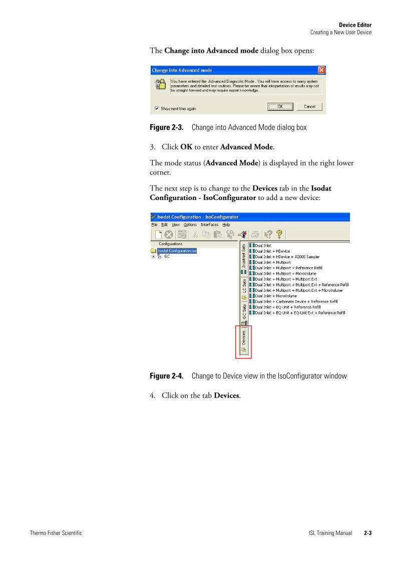
The Change into Advanced mode dialog box opens:
3. Click OK to enter Advanced Mode.
The mode status (Advanced Mode) is displayed in the right lower corner.
The next step is to change to the Devices tab in the Isodat Configuration - IsoConfigurator to add a new device:
4. Click on the tab Devices.
Figure 2-3. Change into Advanced Mode dialog box
Figure 2-4. Change to Device view in the IsoConfigurator window
Thermo Fisher Scientific ISL Training Manual 2-3

Device EditorCreating a New User Device
A window opens that shows the Devices predefined by Thermo Fisher Scientific in its right view:
5. Right-click somewhere in the right view to create a new Device.
The Add User Device button appears:
Note Do not click on an existing Device. ▲
6. Click on the Add User Device button.
The new User Device is added to the Device view:
Figure 2-5. Predefined Devices view
Figure 2-6. Add a new User Device
Figure 2-7. Rename the User Device
2-4 ISL Training Manual Thermo Fisher Scientific

Device EditorEditing a User Device
Editing a User DeviceThe new user device has no content. The content must now be specified.
❖ To specify the content of the new user device
1. Right-click on your new user device, e.g. My Device.
The following list opens:
2. Select the Rename.
3. Uniquely name the new User Device, e.g. My Device.
4. Right-click on My Device.
5. Select the Edit.
Figure 2-8. Right-click menu for device
Table 2-1. Right-click menu items for device
Item Description
Delete Removes the device.
Rename To assigns a new name to the device.
Edit Allows to select a number of objects and to specify their content Objects specified here become components of the device.
Thermo Fisher Scientific ISL Training Manual 2-5

Device EditorEditing a User Device
The opening window shows several tabs:
The following chapters lead you through the configuration of My Device.
Configuring Device Objects
❖ To configure the objects My Device
1. Select the Edit Mode check box in the left lower corner.
Figure 2-9. The tab Device in the Edit window for My Device
Figure 2-10. Device tab for My Device with Edit Mode activated
2-6 ISL Training Manual Thermo Fisher Scientific

Device EditorEditing a User Device
The Device object window appears. In its left view you find various objects or hardware parts.
2. Select the objects you need for My Device and drag and drop them from the left to the right view.
3. Right-click on the hardware objects in the right view.
The following list opens:
For each object there is a parameter dialog with a specific set of parameters, i.e. the Valve parameter dialog differs from the Dac parameter dialog and the Calculating Adc parameter dialog etc.
Figure 2-11. Drag and drop Device objects
Figure 2-12. Right-click menu for a hardware object
Table 2-2. Right-click menu items for hardware objects
Item Description
Delete Removes the device.
Properties To define the properties of the hardware objects.
Thermo Fisher Scientific ISL Training Manual 2-7

Device EditorEditing a User Device
4. Select Properties.
A parameter dialog opens:
The parameters in the upper part of the parameter dialog are the same for all hardware. They will be described below as well as the various Interface Types. The specifics for DIO-, DAC- and ADC-derived classes will also be explained below.
Basic Hardware Parameters
Rename To assigns a new name to the device.
Figure 2-13. Interface Type list in hardware parameter dialog
Table 2-2. Right-click menu items for hardware objects
Item Description
Figure 2-14. Basic hardware parameter dialog
2-8 ISL Training Manual Thermo Fisher Scientific

Device EditorEditing a User Device
Interface Type Fiberline
The Fiberline port is used by Thermo Fisher Scientific peripherals only including the generic Peripheral Controller interface. For detailed information on how to configure the Peripheral Controller, see the Peripheral Controller documentation.
❖ To open the FinniganInterface parameter dialog
1. Follow the description in “Creating a New User Device” on page 2-2, “Editing a User Device” on page 2-5, and “Configuring Device Objects” on page 2-6.
2. Select Fiberline from the Interface Type list (Figure 2-13 on page 2-8).
3. Click on the double arrow button to open the FinniganInterface parameter dialog.
Table 2-3. Basic hardware parameters for object properties
Item Description
Interface Type To select an interface, for example, ‘Fiberline’ (Fiberline is the Thermo Fisher Scientific Interface). Each Interface has its specific parameters.
Optional Activate this check box to be aksed during the configuration set up whether the respective object has been installed.
Standard Inlet Activate this check box for standard inlets. The object (e.g. valve) will appear in the Method under your Reference Ports in the Continuous Flow Module.
Installed Enables the installed object. If this check box is not marked the object will be disabled.
Monitor during Acq Acquisition monitored during acquisition.
Figure 2-15. Open Interface Type FinniganInterface parameter dialog
Thermo Fisher Scientific ISL Training Manual 2-9

Device EditorEditing a User Device
A parameter dialog opens:
Interface Type Gpib
See“Repetition” on page 5-1 for an example where the Gpib interface is used.
❖ To open the GpibInterface parameter dialog
1. Follow the description in “Creating a New User Device” on page 2-2, “Editing a User Device” on page 2-5, and “Configuring Device Objects” on page 2-6.
2. Select Gpib from the Interface Type list (Figure 2-13 on page 2-8).
Figure 2-16. FinniganInterface parameter dialog
Table 2-4. FinniganInterface parameters
Item Description
Basic Address The Basic Address of your Thermo Fisher Scientific MS instrument, refer to the related Hardware Manual.
2nd Address (optional) Optional For internal use only.
Direct Register Access Check the Direct Register Access box and this value will be set anew every second and will not be looped.
Typically, however, you want your data to be looped.
Each value set to the mass spectrometer is typically looped every second by a Digital Signal Processor (DSP).
Use Plug & Measure Activated this will automatically search for the correct instrument port and will assign the needed addresses.
This check box is used for ready-to-use Thermo Fisher Scientific interfaces.
2-10 ISL Training Manual Thermo Fisher Scientific

Device EditorEditing a User Device
3. Click on the double arrow button to open the Gpib parameter dialog.
A parameter dialog opens:
Interface Type Comport Extended
❖ To open the ComportExtInterface parameter dialog
1. Follow the description in “Creating a New User Device” on page 2-2, “Editing a User Device” on page 2-5, and “Configuring Device Objects” on page 2-6.
2. Select Comport Extended from the Interface Type list (Figure 2-13 on page 2-8).
3. Click on the double arrow button to open the Comport Extended parameter dialog.
Figure 2-17. Open Interface Type GpibInterface parameter dialog
Figure 2-18. GpibInterface parameter dialog
Table 2-5. GpibInterface parameters
Item Description
Device Select Code Primary Address of your Gpib device, refer to the related hardware documentation.
Secondary Address Defines sections on your Gpib hardware (often 0).
Port Type Used for internal purposes.
Figure 2-19. Open Interface Type ComportExtInterface parameter dialog
Thermo Fisher Scientific ISL Training Manual 2-11

Device EditorEditing a User Device
A parameter dialog opens:
The ComportExtInterface is an extension of the Comport interface and contains the same parameters.
Figure 2-20. ComportExtInterface parameter dialog
Table 2-6. ComportExtInterface parameters
Item Description
Comport Number Refer to related peripherie manual.
Databits Refer to related peripherie manual.
Stopbits Refer to related peripherie manual.
Baudrate Refer to related peripherie manual.
Parity Possible values: None, Odd, Even, Mark Space.
Refer to related peripherie manual.
Append LF (Line Feet)
Refer to related peripherie manual.
Append CR (Carriage Return)
Refer to related peripherie manual.
Set Parameter Short commands for Send Object and ReceiveObject.
Get Parameter Short commands for Send Object and ReceiveObject.
2-12 ISL Training Manual Thermo Fisher Scientific

Device EditorEditing a User Device
Additionally, the ComportExtInterface permit an easier access to a specific hardware. Short commands allow to set the functions and read the statuses of the hardware.
The user can define the commands Send Object and ReceiveObject. Receive Object contains the answer (if applicable) to the command Send Object. If a Compare Value exists, the ReceiveObject answer will be compared to it. If the ReceiveObject answer corresponds to the Compare Value, the return value of the command is TRUE, otherwise it is FALSE.
For both the Send Object and ReceiveObject there are three commands:
4. Select Text.
The following dialog opens:
Figure 2-21. Commands for Send Object and ReceiveObject
Table 2-7. Send Object and ReceiveObject command parameters
Item Description
None Non defined.
Text Command and expected answer are text
Binary Command and expected answer are binary (Bytes)
Figure 2-22. DataSendReceiveText dialog
Table 2-8. DataSendReceiveText parameters
Item Description
Count Defines the length of the command
Value
Mask Not used for Send Objects
Thermo Fisher Scientific ISL Training Manual 2-13

Device EditorEditing a User Device
5. Select Binary.
The following dialog opens:
Additional parameters can be set for the binary return value.
6. Click on the Number Type list.
The following dialog opens:
In a script you can handle the pump functions with easy Set and Get commands (see LC Isolink Scripts in Global/ISL/LC Isolink or Global/ISL/Lib).
Compare Not used for Send Objects
Figure 2-23. DataSendReceiveBinary dialog
Table 2-9. DataSendReceiveBinary command parameters
Item Description
Count Defines the length of the command
Value
Number Type Additional parameters can be set for the the binary return value.
Byte Mask Filters exactly the Bit that contains the needed information.
Figure 2-24. Number Type list
Table 2-8. DataSendReceiveText parameters, continued
Item Description
2-14 ISL Training Manual Thermo Fisher Scientific
Device EditorEditing a User Device
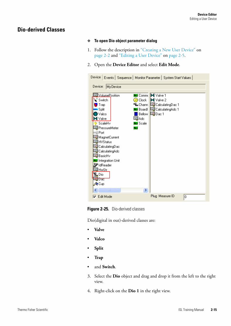
Dio-derived Classes
❖ To open Dio object parameter dialog
1. Follow the description in “Creating a New User Device” on page 2-2 and “Editing a User Device” on page 2-5.
2. Open the Device Editor and select Edit Mode.
Dio(digital in out)-derived classes are:
• Valve
• Valco
• Split
• Trap
• and Switch.
3. Select the Dio object and drag and drop it from the left to the right view.
4. Right-click on the Dio 1 in the right view.
Figure 2-25. Dio-derived classes
Thermo Fisher Scientific ISL Training Manual 2-15

Device EditorEditing a User Device
The following dialog opens:
The specifics are as follows:
Adc-derived Classes
Adc is the main class from which the other Adcs are derived that have the same properties as well as some additional parameters.
Figure 2-26. Dio object hardware parameter dialog
Table 2-10. Specifics of Dio-derived classes
Item Description
Opcode There are official Opcodes for mass spectrometers. Opcode 1 is the standard state, e.g. valve is normally open. The hardware register is in accordance with the state of the DIO. Opcode 2 means inverse state, e.g. valve is normally closed.
Address Code The address code describes an additional address for the object. This parameter is always zero except for the GPIB bus.
Control Code Indicates which bit of the Byte is controlled (1 byte=8 bits). Each interface has its specific Control Codes.
Table 2-11. Control codes
Bit number Gpib Fiberline
0 1 0
1 2 1
2 4 2
3 8 3
4 16 4
5 32 5
6 64 6
7 128 7
2-16 ISL Training Manual Thermo Fisher Scientific

Device EditorEditing a User Device
❖ To open Adc object parameter dialog
1. Follow the description in “Creating a New User Device” on page 2-2 and “Editing a User Device” on page 2-5.
2. Open the Device Editor and select Edit Mode.
Adc(analog digital converter)-derived classes are:
• Adc
• CalculatingAdc
• PressureMeter
• and HVStatus.
3. Select the Adc object and drag and drop it from the left to the right view.
4. Right-click on the Adc 1 in the right view.
Figure 2-27. Adc-derived classes
Thermo Fisher Scientific ISL Training Manual 2-17

Device EditorEditing a User Device
The following dialog opens:
The specifics are as follows:
CalculatingAdc
The CalculatingAdc delivers the values already converted into physical units.
Figure 2-28. AdcHardwarePart parameter dialog
Table 2-12. Specifics of Adc derived classes
Item Description
Minimum The minimum of the Adc (usually 0).
Maximum The maximum of the Adc (e.g. 12-bit ADC = 4095).
Unit The unit of the value (e.g. °C for temperature).
Board The number of the board as defined in the Hardware Manual of your MS.
Channel The channel number as defined in the Hardware Manual of your MS.
Display Format Significant digit of the value (e.g.<%.2f> is equivalent to <two significant digits>).
2-18 ISL Training Manual Thermo Fisher Scientific
Device EditorEditing a User Device
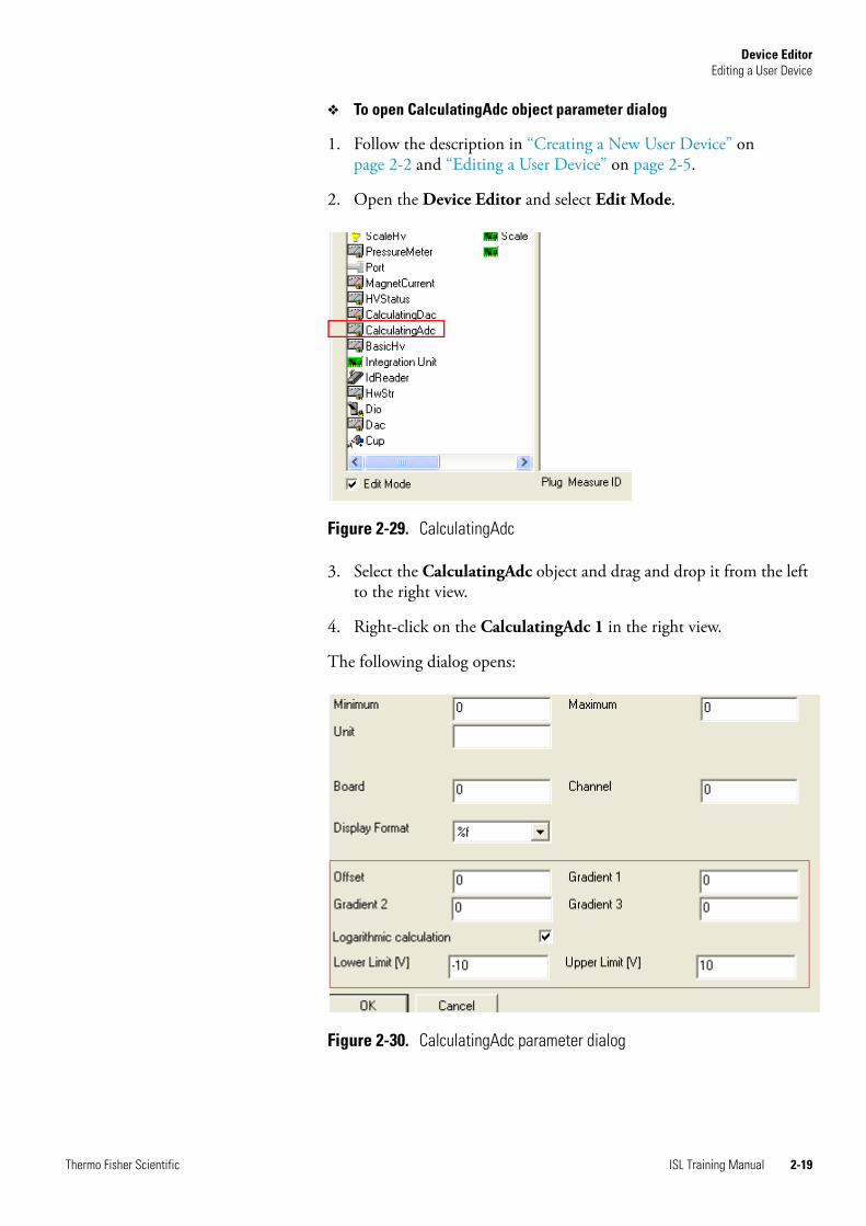
❖ To open CalculatingAdc object parameter dialog
1. Follow the description in “Creating a New User Device” on page 2-2 and “Editing a User Device” on page 2-5.
2. Open the Device Editor and select Edit Mode.
3. Select the CalculatingAdc object and drag and drop it from the left to the right view.
4. Right-click on the CalculatingAdc 1 in the right view.
The following dialog opens:
Figure 2-29. CalculatingAdc
Figure 2-30. CalculatingAdc parameter dialog
Thermo Fisher Scientific ISL Training Manual 2-19

Device EditorEditing a User Device
PressureMeter
❖ To open PressureMeter object parameter dialog
1. Follow the description in “Creating a New User Device” on page 2-2 and “Editing a User Device” on page 2-5.
2. Open the Device Editor and select Edit Mode.
3. Select the PressureMeter object and drag and drop it from the left to the right view.
4. Right-click on the PressureMeter 1 in the right view.
Table 2-13. Specifics of CalculatingAdc dialog
Item Description
Offset
To convert the values into physical units. General formular:Gradient 1
Gradient 2,
Gradient 3
Logarithmic calculation
Uses this formular if check box is selected:
Lower Limit [V] Should be the same as Minimum in Figure 2-12
Upper Limit [V] Should be the same as Maximum in Figure 2-12
f x( ) Gradient 1( )x Gradient 2( )x2 Gradient 3( )x3 Offset( )+ + +=
f2 x( ) log f x( )( )=
Figure 2-31. PressureMeter
2-20 ISL Training Manual Thermo Fisher Scientific

Device EditorEditing a User Device
The following dialog opens:
For the specifics of the dialog parameters, see Figure 2-13. Additionally:
A click on the double arrow opens the following window:
The selection updates the calculation parameters.
HV Status
This object simulates a Dio but is based on an Adc. Internal use only.
Figure 2-32. PressureMeter dialog
Table 2-14. Specifics of PressureMeter dialog
Item Description
User definded To select a predefined vacuum gauges.
Invert voltage For internal use only.
Figure 2-33. PressureMeter user defined vacuum gauges
Thermo Fisher Scientific ISL Training Manual 2-21

Device EditorEditing a User Device
Dac-derived Classes
❖ To open Dac object parameter dialog
1. Follow the description in “Creating a New User Device” on page 2-2 and “Editing a User Device” on page 2-5.
2. Open the Device Editor and select Edit Mode.
Dac(digital analog converter)-derived classes are:
• Dac
• CalculatingDac
• MagnetCurrent
• and BasicHV.
3. Select the Dac object and drag and drop it from the left to the right view.
4. Right-click on the Dac 1 in the right view.
Figure 2-34. Dac-derived classes
2-22 ISL Training Manual Thermo Fisher Scientific

Device EditorEditing a User Device
The following dialog opens:
Their specifics are as follows:
CalculatingDac
❖ To open CalculatingDac object parameter dialog
1. Follow the description in “Creating a New User Device” on page 2-2 and “Editing a User Device” on page 2-5.
2. Open the Device Editor and select Edit Mode.
Figure 2-35. Dac object hardware parameter dialog
Table 2-15. Specifics of Dac object parameter dialog
Item Description
Minimum The minimum of the Dac (usually 0).
Maximum The maximum of the Dac (e.g. 12-bit Adc = 4095).
Unit The unit of the value (e.g. °C for temperature).
Address lo Address code as defined in the Hardware Manual of your MS.
Address hi Address code as defined in the Hardware Manual of your MS.
Start Bit For internal use only.
Significant Bits (0=All)
For internal use only.
Display Format Significant digit of the value (e.g.<%.2f> is equivalent to <two significant digits>).
Thermo Fisher Scientific ISL Training Manual 2-23
Device EditorEditing a User Device
3. Select the CalculatingDac object and drag and drop it from the left to the right view.
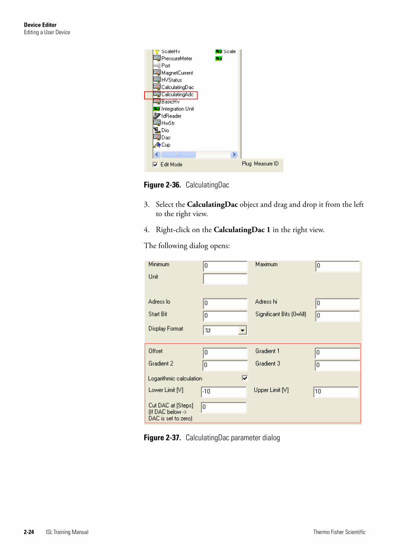
4. Right-click on the CalculatingDac 1 in the right view.
The following dialog opens:
Figure 2-36. CalculatingDac
Figure 2-37. CalculatingDac parameter dialog
2-24 ISL Training Manual Thermo Fisher Scientific

Device EditorEditing a User Device
Magnet Current
Special Dac for internal use only.
Basic HV
Special Dac for internal use only.
Configuring Events
You can also specify time events for a new device. These will then appear in the Thermo Fisher Scientific data acquisition Isodat Method.
Note Time events will only be available in the Continuous Flow acquisition mode. ▲
❖ To specify time events for a new device
1. Open the Edit window for the new device, e.g. My device, as described in “Editing a User Device” on page 2-5.
2. Click on the tab Events.
Table 2-16. Specifics of CalculatingDac dialog
Item Description
Offset
To convert the values into physical units. General formular:Gradient 1
Gradient 2,
Gradient 3
Logarithmic calculation
Uses this formular if check box is selected:
Lower Limit [V] Should be the same as Minimum (see also Figure 2-13)
Upper Limit [V] Should be the same as Maximum (see also Figure 2-13)
Cut DAC at [Steps] (if DAC below -->DAC is set to zero)
For internal use only.
f x( ) Gradient 1( )x Gradient 2( )x2 Gradient 3( )x3 Offset( )+ + +=
f2 x( ) log f x( )( )=
Thermo Fisher Scientific ISL Training Manual 2-25

Device EditorEditing a User Device
The following window opens:
3. Drag and drop an object from the left to the right view. In Isodat Method these can now be set to On or Off.
4. Delete or Rename an item in the Events box by right-clicking on it.
Configuring Sequence
SequenceFlag and SequenceText are used to create additional sequence columns in Isodat Sequence. Device-related parameters can be placed in the sequence. SequenceFlag controls a check mark in your sequence. SequenceText gives you the option to include Proposals.
Note The items SequenceTextSamplerMet, SequenceTextFiles and SequenceCmd are for internal use only. ▲
❖ To specify Sequence for a new device
1. Open the Edit window for the new device, e.g. My device, as described in “Editing a User Device” on page 2-5.
2. Click on the tab Sequence.
The following window opens:
Figure 2-38. The tab Events in the Edit window for My Device
Figure 2-39. The tab Sequence in the Edit window for My Device
2-26 ISL Training Manual Thermo Fisher Scientific

Device EditorEditing a User Device
3. Drag and drop SequenceFlag and SequenceText from the left to the right view.
4. Delete or Rename an item in the Sequence box by right-clicking on it.
SequenceText
SequenceText allows you to define Proposals which can be text or numbers:
5. Edit in the Proposals section as required.
6. Right-click on SequenceText in the right view.
The following window opens:
7. Select Properties from the list.
Figure 2-40. Proposals for SequenceText in the tab Sequence
Figure 2-41. Right-click menu for SequenceText
Thermo Fisher Scientific ISL Training Manual 2-27

Device EditorEditing a User Device
The following window opens:
8. Select the Editable check box to specify whether your object should be editable at any time.
9. Select the Number check box if it should only respond to specific numbers or states that you have defined under Proposals.
SequenceFlag
10. Drag and drop to move SequenceFlag from the left to the right view.
11. Right-click on SequenceFlag in the right view.
The following window opens:
12. Select Properties from the list.
Figure 2-42. Properties for SequenceText
Figure 2-43. Right-click menu for SequenceFlag
2-28 ISL Training Manual Thermo Fisher Scientific

Device EditorEditing a User Device
The following window opens:
Class Name and Object Name are for internal use only.
The Default Value is the value applied to the cells in the newly created sequence column.
13. Select the Default Value check box to activate it.
14. Deselect the Default Value check box to deactivate it.
15. Change the Column Width to the desired value. The standard Column Width is 25 pixel.
Configuring Monitor Parameters
Monitored parameters are frequently read by the system and are send to the visualization objects.
❖ To specify Monitor Parameter for a new device
1. Open the Edit window for the new device, e.g. My device, as described in “Editing a User Device” on page 2-5.
2. Click on the tab Monitor Parameter.
Figure 2-44. Properties for SequenceFlag
Thermo Fisher Scientific ISL Training Manual 2-29

Device EditorEditing a User Device
The following window opens:
3. Drag and drop objects you want to have monitored from the left to the right view.
Configuring System Start Values
You can define system start values for the objects of your new device. For example, you can specify whether your valve should be On or Off after the Isodat system has been started.
❖ To specify System Start Values for a new device
1. Open the Edit window for the new device, e.g. My device, as described in “Editing a User Device” on page 2-5.
2. Click on the tab System Start Values.
3. Drag and drop objects you want to have monitored from the left to the right view.
4. Right-click on the object in the right view.
The following window opens:
Figure 2-45. The tab Monitor Parameter in the DeviceEditor
Figure 2-46. The tab System Start Values in the Device Editor
2-30 ISL Training Manual Thermo Fisher Scientific

Device EditorEditing a User Device
5. Select Properties from the list, e.g. for a valve.
The following window opens:
6. Select On or Off, as appropriate.
7. Confirm with OK.
Figure 2-47. Properties for valve object of System Start Values
Thermo Fisher Scientific ISL Training Manual 2-31

Device EditorClosing the Device Editor
Closing the Device Editor❖ To close the Device Editor
1. In the Device Editor window, click on the red cross in the top left corner.
Figure 2-48. Closing the Device Editor
2-32 ISL Training Manual Thermo Fisher Scientific

Device EditorSelecting an Acquisition Mode
Selecting an Acquisition ModeYou need to select an acquisition mode for your new hardware configuration (Continuous Flow or Dual Inlet).
❖ To select an acquisition mode
1. Open the Isodat Configuration - IsoConfigurator as described in “Creating a New User Device” on page 2-2.
2. Right-click on Isodat Configuration.iso the left view.
The following context menu opens:
3. Select Add Configuration.
4. Drag your device, e.g. My device, from the right view to the left and move it to any port in New Configuration.
5. Right-click on New Configuration.
Figure 2-49. Right-click menu of Isodat Configuration.iso
Figure 2-50. New Configuration added to Configurations
Thermo Fisher Scientific ISL Training Manual 2-33

Device EditorSelecting an Acquisition Mode
The following menu opens:
6. Select Properties.
The following menu opens:
7. Select the acquisition mode as desired.
8. Confirm with OK.
The Default Acquisition Script will be used when creating a new Method for this configuration.
Figure 2-51. Right-click menu New Configuration in the IsoConfigurator
Figure 2-52. Properties of New Configuration
2-34 ISL Training Manual Thermo Fisher Scientific

Device EditorSelecting Interface Modes
Selecting Interface ModesInterfaces can be in either Fake or Active mode. In Fake mode there is no interface available, i.e. it is used just for testing with no actual instrument connected to the computer. In Active Mode the currently connected interface is active.
By clicking on an interface in the Interface menu you can change its status (from active to fake and vice versa).
❖ To select the interface mode
1. Open the Isodat Configuration - IsoConfigurator as described in “Creating a New User Device” on page 2-2.
2. In the main menu select Interfaces.
3. Select the interface and mode you wish to set, e.g. Comport Fake. The menu item is changed to Comport Active.
Figure 2-53. Interface menu in the IsoConfigurator
Thermo Fisher Scientific ISL Training Manual 2-35

Device EditorExporting Isodat Settings to Offline Computers
Exporting Isodat Settings to Offline ComputersYou can export your configuration to an offline computer.
❖ To export Isodat settings
1. Open the Isodat Configuration - IsoConfigurator as described in “Creating a New User Device” on page 2-2.
2. In the main menu select File > Export for Office Installation....
3. Select Export for Office Installation....
4. Select the folder to which you want to export your configuration.
5. Confirm with Open. Your configuration is saved with the file format .std in the chosen folder.
Figure 2-54. File menu in the IsoConfigurator
2-36 ISL Training Manual Thermo Fisher Scientific

Device EditorEXERCISE 1: Create a Device
EXERCISE 1: Create a Device
Task
Your task is to create a new device in the Isodat Configuration - IsoConfigurator with the following specifications:
Solution
❖ To create the new device of EXERCISE 1
1. Create a new device as described in “Creating a New User Device” on page 2-2.
2. Right-click on your new user device My new device and select Edit (“Editing a User Device” on page 2-5). The Device Editor opens.
Table 2-17. Specifications for EXERCISE 1
Item Description
Device name My new device
Device (hardware components)
3 valves (Valve 1, Ref 1, Dilution)
Basic Address; 100, Bit 0-2
Ref 1 is inverse (Opcode=2)
1 Adc (Temperature, Channel 1)
Basic Address: 101
Interface Type: Fiberline
Events all Dios (all valves)
Sequence Volume (editable)
State (selection on/off)
Doit
Monitor Parameter Temperature
System Start Values on (all)
Acquisition mode continuous flow
Thermo Fisher Scientific ISL Training Manual 2-37

Device EditorEXERCISE 1: Create a Device
Defining Hardware Components
Once you are in the Device Editor, assemble your hardware components:
❖ To define hardware components
1. Select the objects as specified in Table 2-17 for My new device and drag and drop them from the left to the right view.
2. Right-click on each object and Rename it according to Table 2-17.
Setting Properties for the Valves
❖ To set properties for hardware components
1. In the Device Editor, right-click on Valve 1 in the right view and select Properties.
The following menu opens:
2. In the Properties window, set Opcode to 1, Address Code and Control Code to 0. For Ref 1, the Opcode must be set to 2.
3. Select the check boxes Installed and Monitor during Acq.
Figure 2-55. The tab Devices for EXERCISE 1
Figure 2-56. Properties of Valve 1 for EXERCISE 1
2-38 ISL Training Manual Thermo Fisher Scientific
Device EditorEXERCISE 1: Create a Device
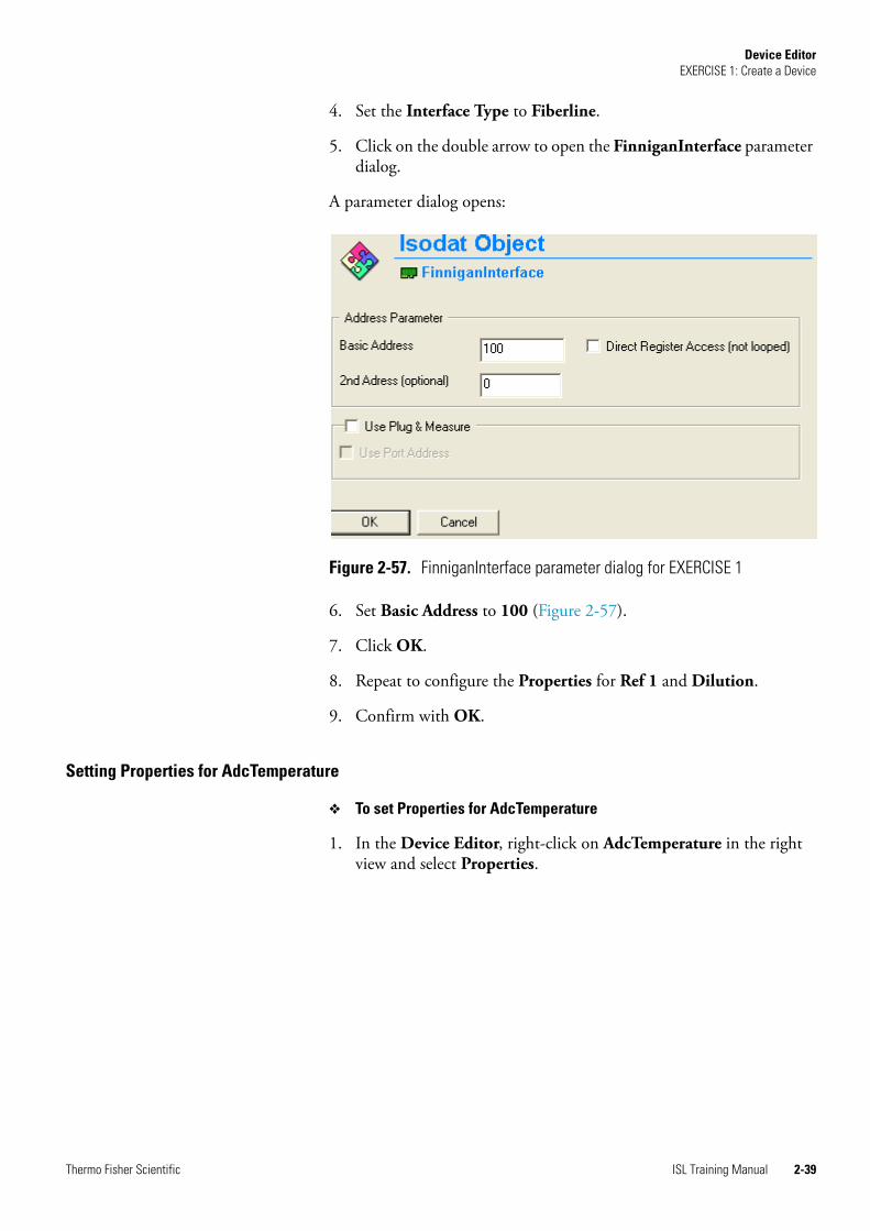
4. Set the Interface Type to Fiberline.
5. Click on the double arrow to open the FinniganInterface parameter dialog.
A parameter dialog opens:
6. Set Basic Address to 100 (Figure 2-57).
7. Click OK.
8. Repeat to configure the Properties for Ref 1 and Dilution.
9. Confirm with OK.
Setting Properties for AdcTemperature
❖ To set Properties for AdcTemperature
1. In the Device Editor, right-click on AdcTemperature in the right view and select Properties.
Figure 2-57. FinniganInterface parameter dialog for EXERCISE 1
Thermo Fisher Scientific ISL Training Manual 2-39

Device EditorEXERCISE 1: Create a Device
The following menu opens:
2. In the Properties window, set Channel to 1.
3. Select the check boxes Installed and Monitor during Acq.
4. Set the Interface Type to Fiberline.
5. Click on the double arrow to open the FinniganInterface parameter dialog.
6. In the FinniganInterface parameter dialog window, set Basic Address to 101 for the AdcTemperature.
7. Confirm with OK.
Defining Events Parameter
❖ To define Events parameter
1. Select the Events tab in the Device Editor.
Figure 2-58. Properties of AdcTemperature for EXERCISE 1
Figure 2-59. Basic Address setting for AdcTemperature in EXERCISE 1
2-40 ISL Training Manual Thermo Fisher Scientific
Device EditorEXERCISE 1: Create a Device
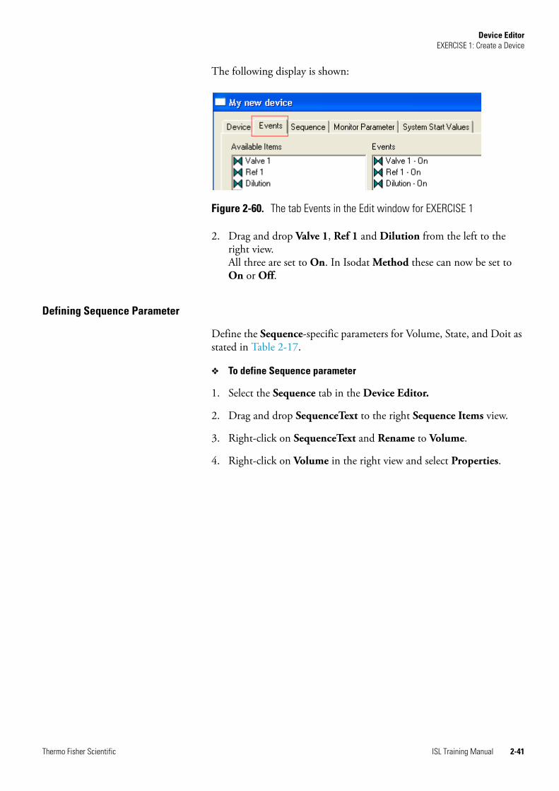
The following display is shown:
2. Drag and drop Valve 1, Ref 1 and Dilution from the left to the right view. All three are set to On. In Isodat Method these can now be set to On or Off.
Defining Sequence Parameter
Define the Sequence-specific parameters for Volume, State, and Doit as stated in Table 2-17.
❖ To define Sequence parameter
1. Select the Sequence tab in the Device Editor.
2. Drag and drop SequenceText to the right Sequence Items view.
3. Right-click on SequenceText and Rename to Volume.
4. Right-click on Volume in the right view and select Properties.
Figure 2-60. The tab Events in the Edit window for EXERCISE 1
Thermo Fisher Scientific ISL Training Manual 2-41
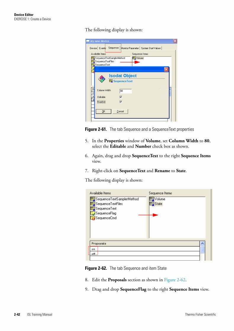
Device EditorEXERCISE 1: Create a Device
The following display is shown:
5. In the Properties window of Volume, set Column Width to 80, select the Editable and Number check box as shown.
6. Again, drag and drop SequenceText to the right Sequence Items view.
7. Right-click on SequenceText and Rename to State.
The following display is shown:
8. Edit the Proposals section as shown in Figure 2-62.
9. Drag and drop SequenceFlag to the right Sequence Items view.
Figure 2-61. The tab Sequence and a SequenceText properties
Figure 2-62. The tab Sequence and item State
2-42 ISL Training Manual Thermo Fisher Scientific

Device EditorEXERCISE 1: Create a Device
10. Right-click on SequenceFlag in the right view and Rename to Doit.
11. Confirm with OK.
Defining Monitor Parameters
❖ To define Monitor Parameters for the AdcTemperature
1. Select the Monitor Parameter tab in the Device Editor.
2. Drag and drop AdcTemperature from the left to the right view. Now it will be monitored.
Defining System Start Values
❖ To define the System Start Values
1. Select the System Start Values tab in the Device Editor.
2. Right-click on the object in the right view, e.g. Valve 1.
3. Select Properties from the list.
Figure 2-63. The tab Sequence and item Doit
Figure 2-64. Defining Monitoring Parameter for ADC
Thermo Fisher Scientific ISL Training Manual 2-43

Device EditorEXERCISE 1: Create a Device
The following window opens:
4. Select On from the list in the Transfer window.
5. Confirm with OK.
6. Repeat to set the System Start Values for all valves to On, as stated in Table 2-17 for EXERCISE 1.
Closing the Device Editor
❖ To close the Device Editor
1. Close the Device Editor as described in “Closing the Device Editor” on page 2-32.
Creating a New Configuration
❖ Create a New Configuration
1. Open the Isodat Configuration - IsoConfigurator as described in “Creating a New User Device” on page 2-2.
2. Right-click on Isodat Configuration.iso the left view.
3. Select Add Configuration. A New Configuration is added in the left Configurations view.
Figure 2-65. Properties for Valve 1 in System Start Values tab
2-44 ISL Training Manual Thermo Fisher Scientific

Device EditorEXERCISE 1: Create a Device
4. Drag and drop My new device from the right view to the left below New Configuration.
A configuration that contains your device is created.
Defining an Acquisition Mode
❖ Define an acquisition mode
1. In the Isodat Configuration - IsoConfigurator, right-click on New Configuration and select Properties.
The following window opens:
Figure 2-66. Add My new device to New Configuration
Figure 2-67. Right-click menu of New Configuration for My new device
Figure 2-68. Configuration window for acquisition mode
Thermo Fisher Scientific ISL Training Manual 2-45

Device EditorEXERCISE 1: Create a Device
2. Select Continuous Flow and confirm with OK.
You finished EXERCISE 1.
2-46 ISL Training Manual Thermo Fisher Scientific

Chapter 3 Panel Designer
With the Panel Designer the users can create panels with active graphical objects to visualize devices and to give direct access to all items of the device.
The following is covered:
• “Creating a New Panel” on page 3-2
• “Creating a Visualization in the Panel” on page 3-4
• “Saving the Visualization” on page 3-15
• “Assigning Visualization” on page 3-16
• “EXERCISE 2: Create a Visualization” on page 3-18
Thermo Fisher Scientific ISL Training Manual 3-1
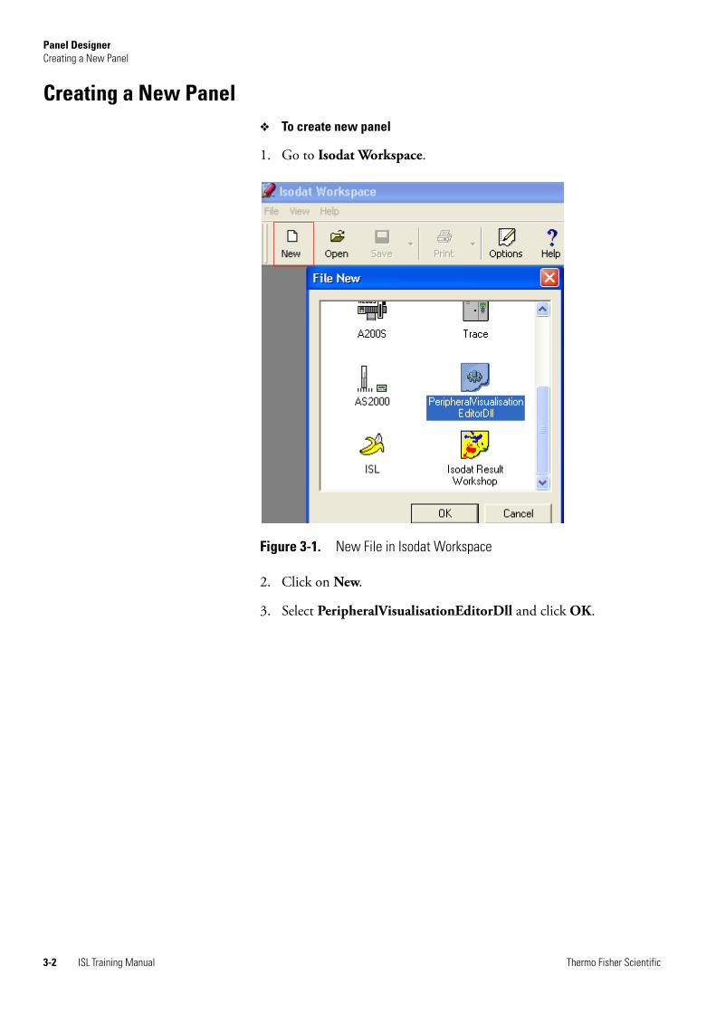
Panel DesignerCreating a New Panel
Creating a New Panel❖ To create new panel
1. Go to Isodat Workspace.
2. Click on New.
3. Select PeripheralVisualisationEditorDll and click OK.
Figure 3-1. New File in Isodat Workspace
3-2 ISL Training Manual Thermo Fisher Scientific
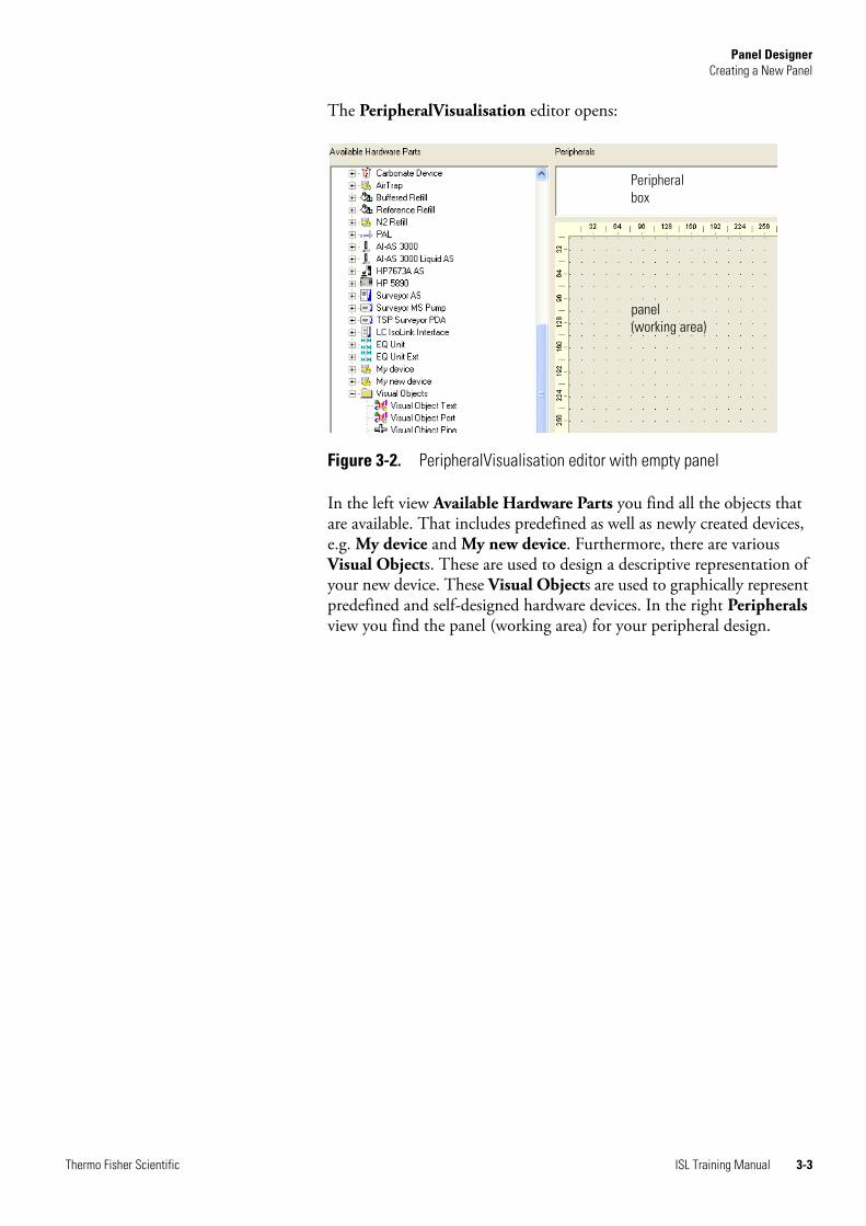
Panel DesignerCreating a New Panel
The PeripheralVisualisation editor opens:
In the left view Available Hardware Parts you find all the objects that are available. That includes predefined as well as newly created devices, e.g. My device and My new device. Furthermore, there are various Visual Objects. These are used to design a descriptive representation of your new device. These Visual Objects are used to graphically represent predefined and self-designed hardware devices. In the right Peripherals view you find the panel (working area) for your peripheral design.
Figure 3-2. PeripheralVisualisation editor with empty panel
panel (working area)
Peripheral box
Thermo Fisher Scientific ISL Training Manual 3-3
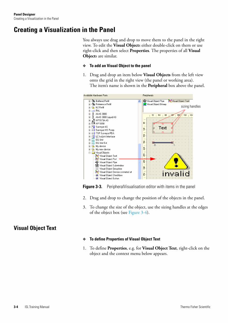
Panel DesignerCreating a Visualization in the Panel
Creating a Visualization in the PanelYou always use drag and drop to move them to the panel in the right view. To edit the Visual Objects either double-click on them or use right-click and then select Properties. The properties of all Visual Objects are similar.
❖ To add an Visual Object to the panel
1. Drag and drop an item below Visual Objects from the left view onto the grid in the right view (the panel or working area). The item’s name is shown in the Peripheral box above the panel.
2. Drag and drop to change the position of the objects in the panel.
3. To change the size of the object, use the sizing handles at the edges of the object box (see Figure 3-4).
Visual Object Text
❖ To define Properties of Visual Object Text
1. To define Properties, e.g. for Visual Object Text, right-click on the object and the context menu below appears.
Figure 3-3. PeripheralVisualisation editor with items in the panel
sizing handles
3-4 ISL Training Manual Thermo Fisher Scientific

Panel DesignerCreating a Visualization in the Panel
2. Select Properties and the following window for Visual Object Text opens.
Note Double-clicking on the object will open the Properties window immediately. ▲
Figure 3-4. Right-click menu of Visual Object Text
Figure 3-5. Properties of Visual Object Text
Table 3-1. Properties for panel objects
Item Description
ISL ID Assigns an ISL ID to the Visual Object by means of which it can be found and analyzed by an ISL script.
Hardware
Border Border gives you the option of four rectangular frames that you can put around your text box (see Figure 3-6). By selecting None you have chosen no border at all.
click to show single dialogs
Thermo Fisher Scientific ISL Training Manual 3-5

Panel DesignerCreating a Visualization in the Panel
List for Border in Figure 3-5:
Example of Text in the panel:
Visual Object Pipe
The Visual Object Pipe is used to illustrate pipes for gas flows. This object can also change its size and direction.
❖ To define Properties of Visual Object Pipe
1. To define Properties right-click on the Visual Object Pipe and the context menu opens.
File To type in the name of a Visual Object which is used as a background picture. You can also specify the path of your object by clicking on the folder symbol. With the checkboxes Stretch and Transparent (slow !) you change the appearance of the text.
Text To type in the text to be displayed in the text box. You can substitute ‘Text’, for example, with ‘First Valve’ (see Figure 3-7).
Font To change font of Visual Object Text description.
Color To change text colour and background colour of Visual Object Text.
To display the background colour uncheck the Transparent check box at the bottom.
Size To change Font size of Visual Object Text description.
Align To change the alignment of Visual Object Text.
Style To change font style of Visual Object Text description by selecting the Bold or Italic check box. If the check box Scale is selected, the text dimensions will change depending on the size of the panel (working area). Otherwise the text dimensions will remain the same, i.e. as originally set.
Figure 3-6. List for Border of Visual Object Text Properties
Figure 3-7. Text in the panel of Visual Object Text Properties
Table 3-1. Properties for panel objects, continued
Item Description
3-6 ISL Training Manual Thermo Fisher Scientific
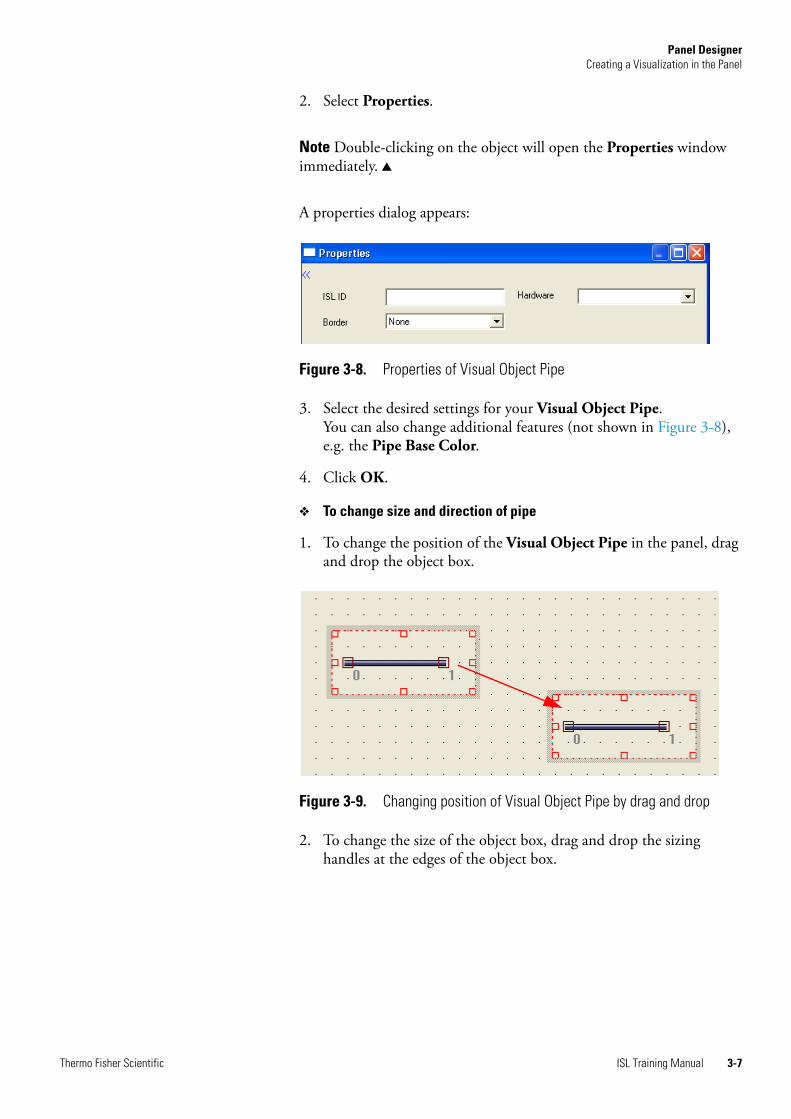
Panel DesignerCreating a Visualization in the Panel
2. Select Properties.
Note Double-clicking on the object will open the Properties window immediately. ▲
A properties dialog appears:
3. Select the desired settings for your Visual Object Pipe. You can also change additional features (not shown in Figure 3-8), e.g. the Pipe Base Color.
4. Click OK.
❖ To change size and direction of pipe
1. To change the position of the Visual Object Pipe in the panel, drag and drop the object box.
2. To change the size of the object box, drag and drop the sizing handles at the edges of the object box.
Figure 3-8. Properties of Visual Object Pipe
Figure 3-9. Changing position of Visual Object Pipe by drag and drop
Thermo Fisher Scientific ISL Training Manual 3-7

Panel DesignerCreating a Visualization in the Panel
3. To change the size (length) of the pipe itself in the Visual Object Pipe box drag and drop the sizing handles at each end of the pipe.
4. To change the direction/orientation of the pipe put your cursor on one of the pipe’s sizing handles, and press the left mouse button and Shift. Keep pressed while dragging and dropping.
5. Right-click on the pipe’s sizing handles for more commands.
Figure 3-10. Changing size of Visual Object Pipe box
Figure 3-11. Changing size of pipe
Figure 3-12. Changed orientation of pipe
3-8 ISL Training Manual Thermo Fisher Scientific

Panel DesignerCreating a Visualization in the Panel
The following menu opens:
Visual Object Valve
❖ To define visualization properties of your valves
1. Drag and drop the Visual Object, for example Valve 1, onto the grid in the right view (the panel or working area). The item’s description is shown in the Peripheral box above the panel.
The design of the valves as blue and horizontal in this case illustrates that they are open.
Figure 3-13. Right-click menu for size handles of pipe
Figure 3-14. Valves dropped into panel
Thermo Fisher Scientific ISL Training Manual 3-9

Panel DesignerCreating a Visualization in the Panel
You can choose different designs to visualize the states of your valves. Another graphic image representing an open valve could be the example below. A closed valve could be presented, for example, by a gray color:
2. Double-click on the Visual Object for valve in the panel.
A properties dialog appears:
Note Note that some more designs (bitmaps) are available in Thermo\Isodat NT\Global\Dynamic Devices\Meta Files. ▲
3. Select a design for the open valve from the pull-down menu Item<Open>.
4. Select a design for the closed valve from the pull-down menu Item <Closed>.
5. Click OK.
Figure 3-15. Example of design for closed and open valve
Figure 3-16. Properties of Visual Object for valve
3-10 ISL Training Manual Thermo Fisher Scientific

Panel DesignerCreating a Visualization in the Panel
Arrange Visual Objects
You can also select several objects in the panel (working area) at the same time and adjust them. For example, you have three Visual Object boxes with different dimensions as illustrated below:
❖ To arrange Visual Objects
1. Click on the first object and then on all other objects you want to resize and align while keeping the Ctrl key pressed. The object that was selected last is the master object and highlighted in red. It determines all adjustments, i.e. the other selected objects will be arranged relative to it.
2. Right-click on any object.
Figure 3-17. Group of Visual Objects
Figure 3-18. Object group with master object highlighted
Thermo Fisher Scientific ISL Training Manual 3-11

Panel DesignerCreating a Visualization in the Panel
A context menu appears:
3. Select Adjust. Another menu opens.
4. Select Same Size.
5. Open the context menu for the object group again as described.
6. Select Adjust. Another menu opens. Select Adjust Top.
Alternatively, you can use the task bar above the panel (working area) and the Peripherals box.
Lock Visual Objects
To make sure that the position of your object will not be changed unintentionally you can lock it:
❖ To lock Visual Object
1. Right-click on the object.
Figure 3-19. Right-click menu of object group
Figure 3-20. Example of resized and aligned objects
Figure 3-21. Task bar to arrange objects
3-12 ISL Training Manual Thermo Fisher Scientific

Panel DesignerCreating a Visualization in the Panel
2. Select Lock in the context menu.
A key symbol appears in the left upper corner of your Visual Object box:
❖ To unlock your object
1. Right-click on it.
2. Select Unlock from the context menu. The key symbol disappears.
Group Visual Objects
Visual Objects can form a group. The command Group in the context menu is used to obtain a logical group.
❖ To group Visual Objects
1. Select at least two objects by clicking on them while keeping the Ctrl key pressed.
2. Right-click on any of the selected objects.
3. Select Group from the context menu.
Figure 3-22. Right-click menu item Lock and locked object
Figure 3-23. Right-click menu item Group
Thermo Fisher Scientific ISL Training Manual 3-13

Panel DesignerCreating a Visualization in the Panel
An entry appears in the Groups box above the panel (working area), in this example Group Index 1:
Those objects which form a group are highlighted in the Peripherals box and are labelled “Group Index 1” in the panel (working area).
Since the shorter pipe on the right was not selected to be included in the group, it is not highlighted in the Peripherals box nor does it have the Groups label.
❖ To ungroup a group:
1. Click on the group and right-click. The context menu opens.
2. Select Ungroup. The name, for example “Group Index 1”, in the Groups box disappears. The objects in the panel (working area) are displayed as individual objects again and are no longer highlighted in the Peripherals box.
Figure 3-24. Grouped objects
3-14 ISL Training Manual Thermo Fisher Scientific

Panel DesignerSaving the Visualization
Saving the VisualizationThe PeripheralVisualisation file must be saved in the Thermo\Isodat NT\Global\Dynamic Devices directory.
❖ To save the visualization
1. In the PeripheralVisualisation editor, go to File > Save As.
2. Type in a descriptive file name, e.g. My new device.
3. Click Save. This PeripheralVisualisation file will now show in the Visualisation Dialogs tab, see “Assigning Visualization” on page 3-16.
Figure 3-25. File menu of PeripheralVisualisation editor
Figure 3-26. Save As menu of PeripheralVisualisation editor
Thermo Fisher Scientific ISL Training Manual 3-15

Panel DesignerAssigning Visualization
Assigning Visualization❖ To assign a Visualization to configuration
1. Open the Isodat Configuration - IsoConfigurator as described in “Creating a New User Device” on page 2-2.
2. In the left Configurations view, right-click on your New Configuration (for creation, see “Selecting an Acquisition Mode” on page 2-33).
3. Select Visualisation Dialogs.
The Visualisation Dialogs window opens. My new device is listed in the left view.
4. Drag and drop My new device into the right view.
5. Close the Isodat Configuration - IsoConfigurator. The PeripheralVisualisation file My new device is assigned to New Configuration.
Figure 3-27. Selecting Visualisation Dialogs in Configurations
Figure 3-28. Visualisation Dialogs window of New Configuration
3-16 ISL Training Manual Thermo Fisher Scientific

Panel DesignerAssigning Visualization
6. Open the Isodat Acquisition program. Your new device panel will be displayed in the accessory bar. All active objects can now be accessed and are able to control My new device.
Note Visualization panels only appear in programs with access to the instrument. ▲
Thermo Fisher Scientific ISL Training Manual 3-17

Panel DesignerEXERCISE 2: Create a Visualization
EXERCISE 2: Create a VisualizationIn “EXERCISE 1: Create a Device” on page 2-37 My new device was created. This device shall now be visually displayed.
Task
The following Peripheral Visualisation is to be created for the devices in Table 2-17 on page 2-37.:
Solution
Creating New Panel
❖ To create new panel
1. Go to Isodat Workspace.
2. Click on New.
3. Select PeripheralVisualisationEditorDll and click OK.
4. In the Available Hardware Parts view click on the plus sign for My new device to display the particular components for this device.
Figure 3-29. Specification for EXERCISE 2
3-18 ISL Training Manual Thermo Fisher Scientific

Panel DesignerEXERCISE 2: Create a Visualization
If you go to Events and Sequence in My new device and click on the plus sign you will see the parameters that you have set to your valves in the Device Editor in “EXERCISE 1: Create a Device” on page 2-37.
Defining Visualization of Valves
❖ To define the visualization of your valves
1. Drag and drop My new device@Valve 1 (see Figure 3-30), into the panel (working area).
2. Double-click on the Visual Object for valve in the panel.
3. Select a design for the opened valve from the pull-down menu Item<Open>.
4. Select a design for the closed valve from the pull-down menu Item<Closed>.
5. Click OK.
Figure 3-30. Components of My new device
Figure 3-31. Parameters of Events and Sequence for My new device
Thermo Fisher Scientific ISL Training Manual 3-19

Panel DesignerEXERCISE 2: Create a Visualization
6. Repeat to define the visualization for the valves My new device@Ref 1 and My new device@Dilution.
Defining Visualization of AdcTemperature
❖ To define the visualization of Adc Temperature
1. Drag and drop My new device@Adc Temperature (see Figure 3-30), into the panel (working area).
2. Double-click on the Visual Object for Adc Temperature in the panel.
3. Select a design.
4. Click OK.
Assigning Names to the Valves
❖ To assign names to the valves
1. Drag and drop Visual Object Text next to the Visual Object Valve on the panel (working area).
2. Double-click on the Visual Object Text box in the panel to define the properties.
Figure 3-32. Visual Object Text for valve
Figure 3-33. Text properties in Properties window for Visual Object Text
3-20 ISL Training Manual Thermo Fisher Scientific

Panel DesignerEXERCISE 2: Create a Visualization
3. Type in the name, e.g. type in Valve 1.
4. Define a text color and the size of the text.
5. Repeat to define properties for Ref 1, Dilution.
Connecting the Three Valves and Adc Temperature with Pipes
You can now connect the three valves and the Adc Temperature of My new device with pipes and assign names to them.
❖ To connect the three valves and the Adc Temperature with pipes
1. To visualize the pipes connecting the valves, drag and drop the Visual Object Pipe to the right.
2. Arrange the pipes for Valve 1 and Ref 1 as defined in Figure 3-29.
3. Continue to arrange the pipes for Dilution and Adc Temperature as defined in Figure 3-29.
Saving the Visualization
For a detailed description, see “Saving the Visualization” on page 3-15.
❖ To save PeripheralVisualisation file
1. In the PeripheralVisualisation editor, go to File > Save As.
Figure 3-34. Visual Object Valve with Visual Object Text
Figure 3-35. Valve 1 and Ref 1 connected with pipes
Thermo Fisher Scientific ISL Training Manual 3-21

Panel DesignerEXERCISE 2: Create a Visualization
2. Type in a descriptive file name.
3. Click Save.
Assigning a Visualization Dialog
For a detailed description, see “Assigning Visualization” on page 3-16.
❖ To assign a Visualisation Dialog
1. In the Configurations view on the left, right-click on New Configuration to open the Visualisation Dialogs window.
2. Drag and drop My new device into the right view.
3. Close the Isodat Configuration - IsoConfigurator.
You finished EXERCISE 2.
3-22 ISL Training Manual Thermo Fisher Scientific

Chapter 4 ISL Programming
With the help of the ISL edit mode you can write and edit scripts.
The following is covered:
• “The ISL Library Concept” on page 4-2
• “Functions” on page 4-4
• “Dynamic Externals” on page 4-7
• “Opening the ISL Edit Mode” on page 4-9
• “Debugging” on page 4-14
• “Save Script” on page 4-17
• “EXERCISE 3: Write a Script” on page 4-18
• “EXERCISE 4: Write Functions” on page 4-21
• “EXERCISE 5: Read Entries in a Sequence” on page 4-23
• “EXERCISE 6: Create Parameters for Methods” on page 4-24
• “EXERCISE 7: Declaration of Dynamic Externals, Call Dialog and Evaluation” on page 4-25
Thermo Fisher Scientific ISL Training Manual 4-1

ISL ProgrammingThe ISL Library Concept
The ISL Library ConceptA library is a place for functions to be used by more than one script. You can also use a library from a library if you need a function which was already defined there.
Note A change in a library will cause changes in all scripts which use this function from this library. ▲
There are libraries in Isodat with a high functionality. Do not change them. Create your own library and include any library you need.
❖ To write a library
1. Write your function in an ISL script the same way you would write an ordinary script, see description “EXERCISE 3: Write a Script” on page 4-18.
Note Libraries must not contain the entry point <main> ▲.
Figure 4-1. Library in ISL
4-2 ISL Training Manual Thermo Fisher Scientific

ISL ProgrammingThe ISL Library Concept
2. Write the path before the library only if you save the library in a different directory than the default script directory. In case the directory is a sub-directory of the default script directory (standard script directory) you can place the path relative to it. If you save the library in the default script directory, you do not need to place a path before the library.
Example of script where libraries are included:
Figure 4-2. ISL script showing included libraries
Thermo Fisher Scientific ISL Training Manual 4-3

ISL ProgrammingFunctions
FunctionsA function helps to structure a program. Functions contain various parts of a program that can be repeatedly executed. They can be called with a user defined argument list and are able to return one value directly. However, functions can return any number of values with referenced arguments. Referenced arguments are variables which can be changed in a called function.
The generic form of a function looks as illustrated below. The asterisk * denotes ‘value by reference’, variables in square brackets [ ] are optional:
function FunctionName([vartype[*] Var],[...]) [:vartype]
{
//your function characteristics
[returned result;]
}
fdsgadfdafa
Core Functions/Internal ISL Functions
There are various functions already available to be included in scripts. These are the core or internal ISL functions. It is recommended to get an overview of these functions before writing a script.
Overview of Core Functions
You can also use the ISL Online Help to get an idea of the structure and functionality of various internal ISL functions.
❖ To open the Online Help
1. In the ISL edit mode in the Isodat Workspace press the function key F1.
2. Go to Statements and a chapter list of some core functions opens.
3. Select one chapter to for more detailed information.
4-4 ISL Training Manual Thermo Fisher Scientific

ISL ProgrammingFunctions
Inserting Functions
❖ To insert core functions
1. Right-click in an open script. A right-click anywhere in an ISL script opens the context menu (see “Context Menu” on page 4-12).
2. Select Insert Function.
Note Alternatively, you can ress Shift + Ctlr + F. ▲
Figure 4-3. Online Help in ISL
Thermo Fisher Scientific ISL Training Manual 4-5

ISL ProgrammingFunctions
The box below opens, which can be enlarged by dragging its margins:
3. Double-click to select a function and insert it in your script.
Viewing Function Argument List
When you are working with scripts in the ISL edit mode you can view the arguments of a function.
❖ To show function argument list
1. Go to a core function name in a script, for example _Get and _Delay, and click on it.
2. Keep the cursor on the function. After a second a tool tip will appear showing the complete argument list of the respective function.
User-implemented Functions
You can also create your own functions and add them to the function list.
Functions are introduced by the keyword function followed by a user defined name, an argument list, a colon and a definition of the return value.
Figure 4-4. Core functions in ISL
Figure 4-5. Functions and tooltips in ISL
4-6 ISL Training Manual Thermo Fisher Scientific

ISL ProgrammingDynamic Externals
Dynamic ExternalsIt is possible to declare dynamic externals in ISL. Dynamic Externals are dynamic external variables, which can be changed externally, i.e. the script itself does not have to be changed because the dynamic externals can be parametered outside a script. You can modify Isodat Methods with Dynamic Externals.
To declare a dynamic external the following steps are necessary:
A default value must be assigned to all variables, except objects. The appearance in a dialog can be influenced as follows:
It is necessary that the dialog parameters for the variables are located in the same line as the declaration:
If you want to add to the style of your dialog you can use the following dynexternal types:
Note For a demonstration code see the ISL Online help. Go to Variables and continue with Dynamic Externals in der Online Help. s
Figure 4-6. Declare dynamic externals in ISL
Figure 4-7. Assign default value to variables in ISL
Figure 4-8. Parameters in same line in ISL
Figure 4-9. Dynexternal types in ISL
Thermo Fisher Scientific ISL Training Manual 4-7

ISL ProgrammingDynamic Externals
The function _Do DynExternalModal brings a property dialog on screen. With the help of this property dialog the DynExternal variables can be edited. The function _Do DynExternalModal displays all valid/declared dynamic externals in the running script including dynamic externals in a library. When the optional parameter positions strTab1 etc. are filled, only those dialog(s) will be displayed that have the name which corresponds to these optional parameters. All dialog(s) will be displayed if no optional parameter is given.
The result of the function _DoDynExternalModal is IDOK if the user selected OK, otherwise it is IDCANCEL.
Modal means blocking the application, i.e. you can only continue when the modal dialog is finished.
Figure 4-10. Declare dynamic externals results in ISL
4-8 ISL Training Manual Thermo Fisher Scientific
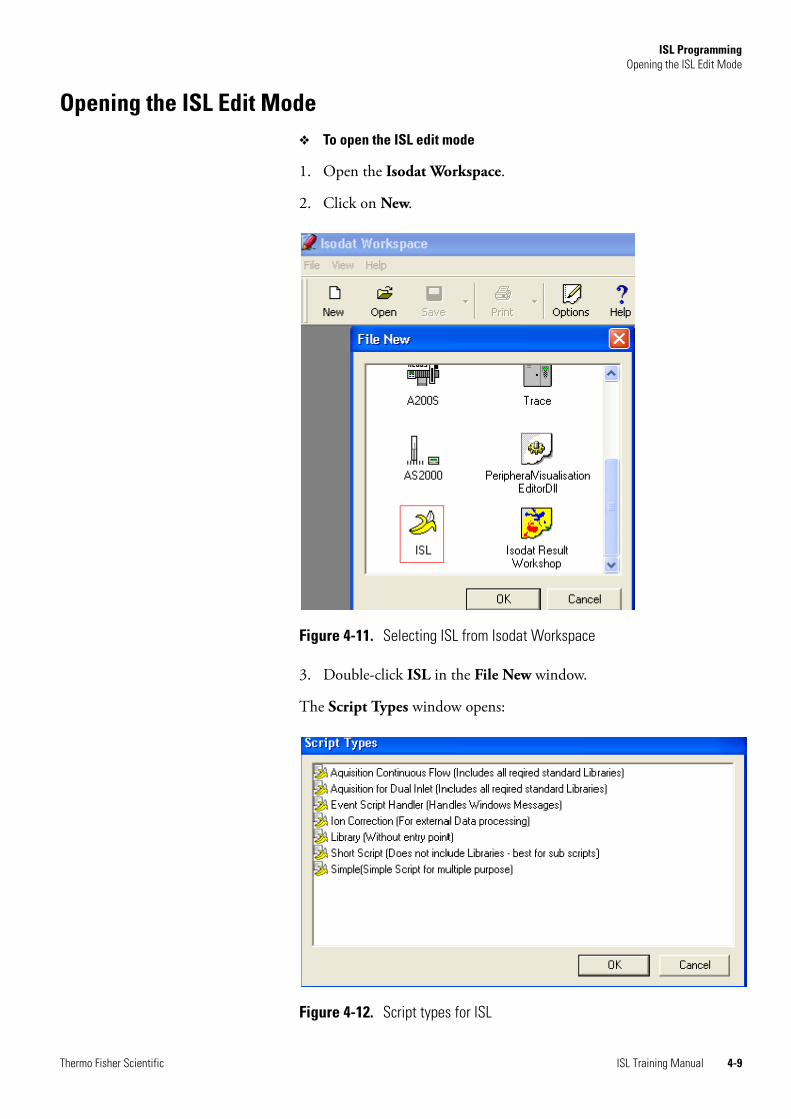
ISL ProgrammingOpening the ISL Edit Mode
Opening the ISL Edit Mode❖ To open the ISL edit mode
1. Open the Isodat Workspace.
2. Click on New.
3. Double-click ISL in the File New window.
The Script Types window opens:
Figure 4-11. Selecting ISL from Isodat Workspace
Figure 4-12. Script types for ISL
Thermo Fisher Scientific ISL Training Manual 4-9

ISL ProgrammingOpening the ISL Edit Mode
4. Select the desired script from the list.
5. Click OK.
6. The ISL edit mode is opened.
Note Double-clicking also selects the script and opens the ISL edit mode. ▲
ISL Script Types
The following script types are available:
Table 4-1. Script Types
Item Description
Acqusition Continuous Flow
Script for continuous flow acquisition. Use this template to create a new acquisition script for Continuous Flow.
Acquisition for Dual Inleet
Script for dual inlet acquisition. Use this template to create a new acquisition script for Dual Inlet.
Event Script Handler Script for event script handler. Use this template to catch events from the system for your own processing requirements. The commonly used event is the peak event. You can, for example, switch on a dilution on a specified peak height.
Ion Correction Script for ion correction. Use this template to create your own evaluation rule. For further information on evaluation scripts.
Library Script for libraries. Use this template to create a new library. It must not contain the entry point < main >. A library is useful for functions that are used from different scripts.
Short Script Short script. This template is useful for underlying control scripts. If you have a Peripheral Visualisation you can select this script type in Properties of the active objects. It guarantees quick script execution.
Simple Simple script. This template is best for programming experiments with an instrument. It includes the basic libraries for instrument control and user interaction.
4-10 ISL Training Manual Thermo Fisher Scientific

ISL ProgrammingOpening the ISL Edit Mode
ISL Script Structure
If you have selected Simple (Simple Script for multiple purpose), for example, the script will show the following script structure:
Commonly Used Symbols in ISL Edit Mode
Various symbols, which are commonly used in ISL, will be explained below.
Figure 4-13. Example of script structure
Table 4-2. Symbols in ISL edit mode
Item Description
//
forward double slash
All of the green lines in a script are comments. However, this symbol is used only for single-line comments.
/* */
forward slash asterisk
This symbol also indicates comments in a script. It is used for comment blocks, i.e. more than one line. Insert /* where the block begins and */ where it ends.
;
semicolon
The semicolon indicates the end of a statement and is required.
{ }
curly brackets
This symbol denotes the beginning and the end of a scope, i.e. it marks the begin and the end of a function body.
( )
parentheses
These brackets begin and end an argument list, and they define a mathematical evaluation order.
Thermo Fisher Scientific ISL Training Manual 4-11

ISL ProgrammingOpening the ISL Edit Mode
Color Syntax in ISL
Tools in the ISL Edit Mode
The help and the context menu are provides when working with the ISL edit mode. The function key F1 opens the ISL Help when you are in ISL edit mode. The context menu opens with a right-click
Help
❖ To open the ISL Help
1. Position cursor on a string and press F1.
The current variable or function will be accessed and the corresponding help topic in the ISL Help will be opened. The ISL Help is context-sensitive.
Context Menu
The context menu provides helpful commands.
❖ To open the context menu
1. Right-click anywhere in an ISL script.
A right-click anywhere in an ISL script opens the context menu:
Table 4-3. Color syntax in ISL edit mode
Item Description
blue Denotes a control structure located in the ISL core and a string value.
lavender Denotes a core function.
black Denotes common source code.
red Denotes a number value.
green Denotes a comment, no functionality.
Figure 4-14. Context menu in ISL edit mode
4-12 ISL Training Manual Thermo Fisher Scientific

ISL ProgrammingOpening the ISL Edit Mode
Table 4-4. Context menu commands in ISL edit mode
Item Description
Open File... Opens the file under the cursor
Goto Definition Jumps to the definition of the function which is below the cursor (Note this command does not work with core functions).
Insert Device Item (Cnf)
Opens a list of hardware items of the current configuration. Items are inserted by double-click or by pressing Enter. The selected device item will be inserted at cursor position. The key Esc cancels the selection.
Insert Device Item (All) Opens a list of hardware items of the system (i.e. not of the current configuration). Items are inserted by double-click or by pressing Enter. The selected device item will be inserted at cursor position. The key Esc cancels the selection.
Insert Function Opens a list of available internal functions. Function is inserted by double-click or by pressing Enter. The selected function will be inserted at cursor position. The key Esc cancels the selection.
Thermo Fisher Scientific ISL Training Manual 4-13
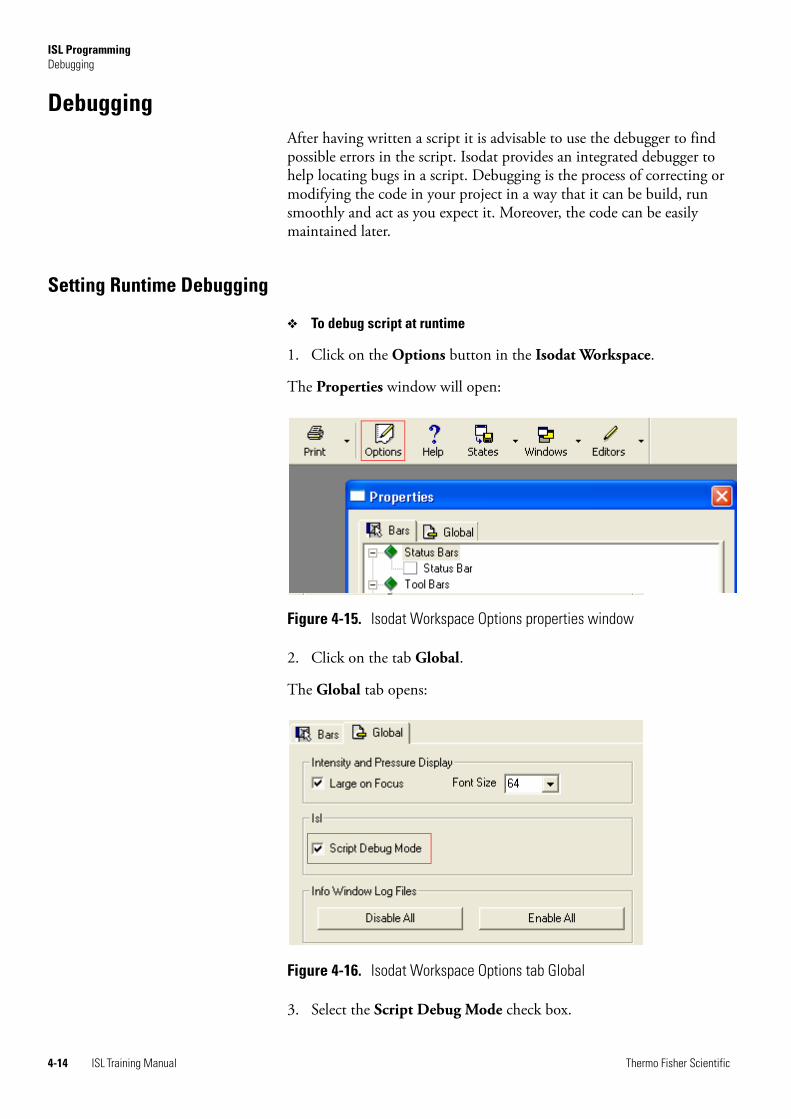
ISL ProgrammingDebugging
DebuggingAfter having written a script it is advisable to use the debugger to find possible errors in the script. Isodat provides an integrated debugger to help locating bugs in a script. Debugging is the process of correcting or modifying the code in your project in a way that it can be build, run smoothly and act as you expect it. Moreover, the code can be easily maintained later.
Setting Runtime Debugging
❖ To debug script at runtime
1. Click on the Options button in the Isodat Workspace.
The Properties window will open:
2. Click on the tab Global.
The Global tab opens:
3. Select the Script Debug Mode check box.
Figure 4-15. Isodat Workspace Options properties window
Figure 4-16. Isodat Workspace Options tab Global
4-14 ISL Training Manual Thermo Fisher Scientific
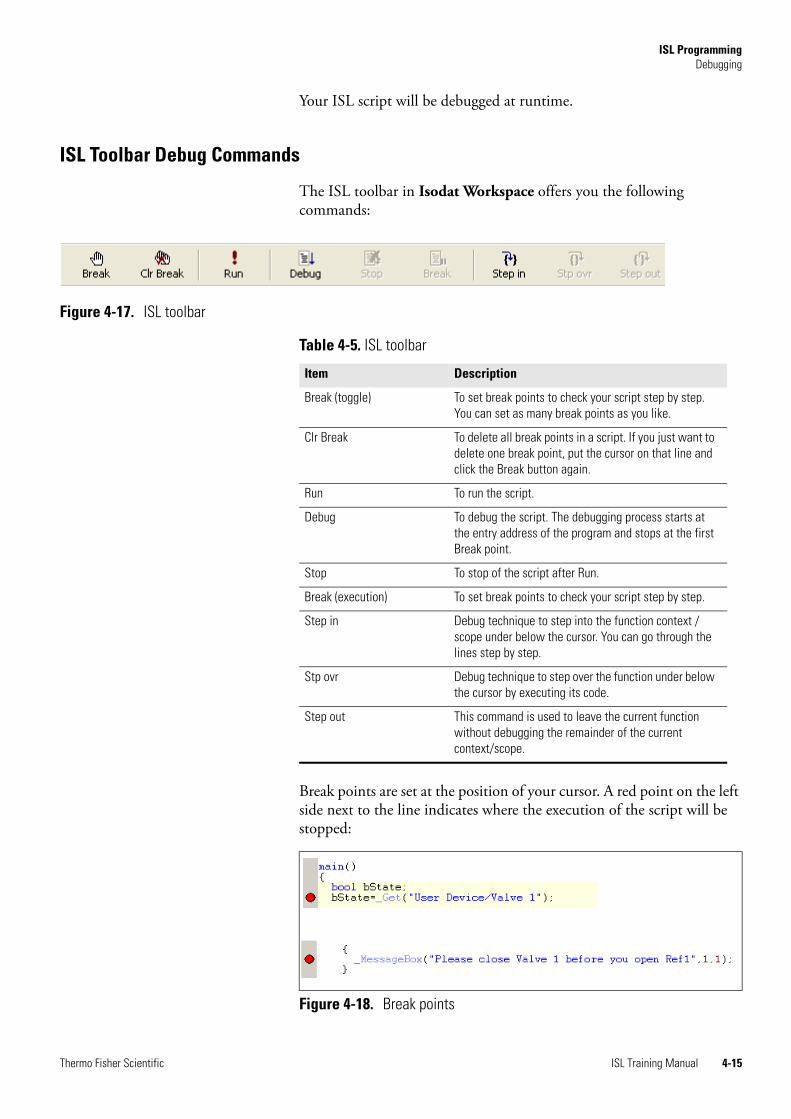
ISL ProgrammingDebugging
Your ISL script will be debugged at runtime.
ISL Toolbar Debug Commands
The ISL toolbar in Isodat Workspace offers you the following commands:
Break points are set at the position of your cursor. A red point on the left side next to the line indicates where the execution of the script will be stopped:
Figure 4-17. ISL toolbar
Table 4-5. ISL toolbar
Item Description
Break (toggle) To set break points to check your script step by step. You can set as many break points as you like.
Clr Break To delete all break points in a script. If you just want to delete one break point, put the cursor on that line and click the Break button again.
Run To run the script.
Debug To debug the script. The debugging process starts at the entry address of the program and stops at the first Break point.
Stop To stop of the script after Run.
Break (execution) To set break points to check your script step by step.
Step in Debug technique to step into the function context / scope under below the cursor. You can go through the lines step by step.
Stp ovr Debug technique to step over the function under below the cursor by executing its code.
Step out This command is used to leave the current function without debugging the remainder of the current context/scope.
Figure 4-18. Break points
Thermo Fisher Scientific ISL Training Manual 4-15

ISL ProgrammingDebugging
After the debugging process Break points are replaced by a yellow line and a yellow arrow, the program pointer:
If the debugger finds an error, this will be indicated by a red X and a red line in the script:
Debug Bar
The content of the debuggee is displayed in the Debug bar. The Debug bar can either be on or off. The visibility of the Debug bar is controlled by the Watch button in the toolbar. However, the Debug bar is shown automatically when starting the debug process.
Figure 4-19. After debugging
Figure 4-20. ISL debugging output
Figure 4-21. ISL Debug bar Watch button
4-16 ISL Training Manual Thermo Fisher Scientific

ISL ProgrammingSave Script
Save Script❖ To save the script
1. In the ISL edit mode, select File > Save as.
2. Select the path where you want to save the script and type in a name. Your script will be saved in the file format .isl.
Table 4-6. Debug bar function windows
Item Description
Variables The Variables window displays all defined variables in the current script and its libraries. The Variables display is structured by function contexts.
You can also view the value of the variable by keeping the cursor on the variable in the script.
Functions To display all functions defined in the current script as well as its libraries.
Call Stack The Call Stack window displays the path (flow diagram) through the functions up to the current location of the program pointer. If you leave a function scope the entry will be removed from the Call Stack window.
The top entry in the Call Stack window is the current function (current location of the program pointer).
Thread To display all running threads created from this script and its libraries.
Thermo Fisher Scientific ISL Training Manual 4-17
ISL ProgrammingEXERCISE 3: Write a Script
EXERCISE 3: Write a ScriptIn “EXERCISE 1: Create a Device” on page 2-37 and “EXERCISE 2: Create a Visualization” on page 3-18 the device My new device was created and visualized. The valves of this device now have to be programmed with the help of a script. Remember, My new device consists of three valves: Valve 1, Ref 1 and Dilution.
Task
Your task is to write a script where:
• Ref 1 may only be opened if Valve 1 is closed.
• If it is tried to open Ref1 when Valve 1 is still open, a message box must displayed.
• The warning message must say that Valve 1 has to be closed before Ref 1 can be opened.
Note To check the state of the two valves (Valve 1 and Ref 1) only one variable (bState) is necessary. After the status of Valve 1 has been checked and a decision has been made (if or else), the old value of bState becomes obsolete. ▲
Solution
❖ To select ISL scripts
1. Open the Isodat Workspace.
2. Click on New and select ISL.
3. Select the script Short Script in Script Types window.
Creating Variable
First, the state of Valve 1 needs to be checked:
• If Valve 1 is closed, switch valve as required
• If Valve 1 is open, display message box with warning
With a variable to which a Boolean value is assigned, the value can either be 0 (TRUE) or 1 (FALSE) depending on the state of Valve 1.
❖ To create the variable bState
1. Type bool bState to define a variable to which a Boolean value is assigned, in our example bState.
4-18 ISL Training Manual Thermo Fisher Scientific

ISL ProgrammingEXERCISE 3: Write a Script
Writing Script to Check the Variable
❖ To check the state of Valve 1
1. Write the script to check the state of Valve 1.
If Valve 1 is open and Ref 1 is to be opened, a message box must display the comment that Valve 1 needs to be closed before Ref 1 can be opened.
❖ To insert the function _MessageBox
1. Right-click at the desired position in the ISL script.
2. Click Insert Function (see Figure 4-14).
3. Select _MessageBox from the list of available internal functions.
❖ To finish the script
If Ref 1 is going to be closed, no restrictions apply, just close Ref 1.
1. Insert the function to close Ref 1.
Figure 4-22. Script checking state of Valve 1
Figure 4-23. Script with function _MessageBox
Figure 4-24. Script to close Ref 1
Thermo Fisher Scientific ISL Training Manual 4-19

ISL ProgrammingEXERCISE 3: Write a Script
Below you find the complete script:
Debugging the script
❖ To debug the script
1. Select Break from the ISL toolbar to set break point where desired.
2. Select Debug from the ISL toolbar.
3. Check the result of the debugging process in the Debug bar. Correct, where necessary.
Figure 4-25. Complete script to check state of Valve 1
4-20 ISL Training Manual Thermo Fisher Scientific

ISL ProgrammingEXERCISE 4: Write Functions
EXERCISE 4: Write Functions
Task
The task is to write a function f1 that returns n3/2:
The task is to write a function f2 that returns sqr(n) and n2:
Useful core functions for this exercise are _strFormat and _MessageBox.
Solution
❖ To create the function
1. Click on New in the Isodat Workspace
2. Select ISL.
3. Select Short Script from the Script Types window.
4. Define the functions f1 und f2.
5. Write the functions using the core functions _strFormat and _MessageBox.
f n( ) n3
2-----=
f n( ) n=
f n( ) n2=
Thermo Fisher Scientific ISL Training Manual 4-21

ISL ProgrammingEXERCISE 4: Write Functions
The complete script:
Figure 4-26. ISL Programming functions EXERCISE 5
4-22 ISL Training Manual Thermo Fisher Scientific

ISL ProgrammingEXERCISE 5: Read Entries in a Sequence
EXERCISE 5: Read Entries in a Sequence
Task
Read the entries in a sequence:
• _GetSequenceNumber
• _GetSequenceText
• _GetSequenceFlag
Thermo Fisher Scientific ISL Training Manual 4-23

ISL ProgrammingEXERCISE 6: Create Parameters for Methods
EXERCISE 6: Create Parameters for Methods
Task
“My 2nd New Device”
New Isodat Methods pages with:
• EQ (yes/no) bool
• EQ-Time [sec] number
• EQ-Channel channel
• Create Library incl.:
• Function: Prepare( )
• Wait delay time
• If EQ activated
4-24 ISL Training Manual Thermo Fisher Scientific

ISL ProgrammingEXERCISE 7: Declaration of Dynamic Externals, Call Dialog and Evaluation
EXERCISE 7: Declaration of Dynamic Externals, Call Dialog and Evaluation
This exercise is an extension of EXERCISE 5 (see “EXERCISE 4: Write Functions” on page 4-21) to modify a method through Dynamic Externals.
Task
Create an Interfering Masses Tab Page:
• Declaration of Dynamic Externals
• Call Dialog
• Evaluation of numbers
Thermo Fisher Scientific ISL Training Manual 4-25


Chapter 5 Repetition
The repetition shall be used to review “Device Editor” on page 2-1, “Panel Designer” on page 3-1 and “ISL Programming” on page 4-1.
The following is covered:
• “Task” on page 5-2
• “Creating a New Device” on page 5-2
• “Selecting Acqusition Mode” on page 5-7
• “Creating the Visualization in the New Panel” on page 5-9
• “Writing the Scripts” on page 5-12
• “Assigning the Scripts to the Valves” on page 5-15
• “Testing the Scripts” on page 5-17
Thermo Fisher Scientific ISL Training Manual 5-1

RepetitionTask
TaskYour task is to:
• create a new device
• to create a visualization for it
• to write scripts
• to assign the scripts to valves
The device to create is a Standard Changeover with the following specifications:
Scripts to generate these three valve states for the Standard Changeover are to be created:
Creating a New Device❖ To create a new device
1. Add a new device to the left Configurations view in Isodat Configuration - IsoConfigurator as described in “Creating a New User Device” on page 2-2.
Table 5-1. Device specifications for repetition
Item Description
Hardware parts /Device 4 valves (31, 32, 33, 34)
Interface Gpib
Address Code 32
Device Select Code 26
Sequence entries position (left/right)
delay (in milliseconds)
System Start Values 31 and 32 Off
33 and 34 On
Acquisition mode dual inlet
Scripts see Figure 5-1
Figure 5-1. Valve scripts to be created for repetition
= Off
= OnClose Left Right
5-2 ISL Training Manual Thermo Fisher Scientific

RepetitionCreating a New Device
2. Via the right-click menu, Rename the new device, e.g. my new changeover.
3. Change to the Edit mode in the Device Editor, as described in “Editing a User Device” on page 2-5.
Configuring the New Device
The configuration of the hardware devices is described in detail in “Configuring Device Objects” on page 2-6.
❖ To configure the new device
• In the Device Editor, drag and drop four valve objects from the left to the right view.
4. Right-click and Rename according to Figure 5-2.
Configuring Events
❖ To specify Events
1. Select the tab Device in the Device Editor.
2. For each valve, right-click in the right view and select Properties.
Figure 5-2. Hardware devices in Device Editor in repetition
Thermo Fisher Scientific ISL Training Manual 5-3
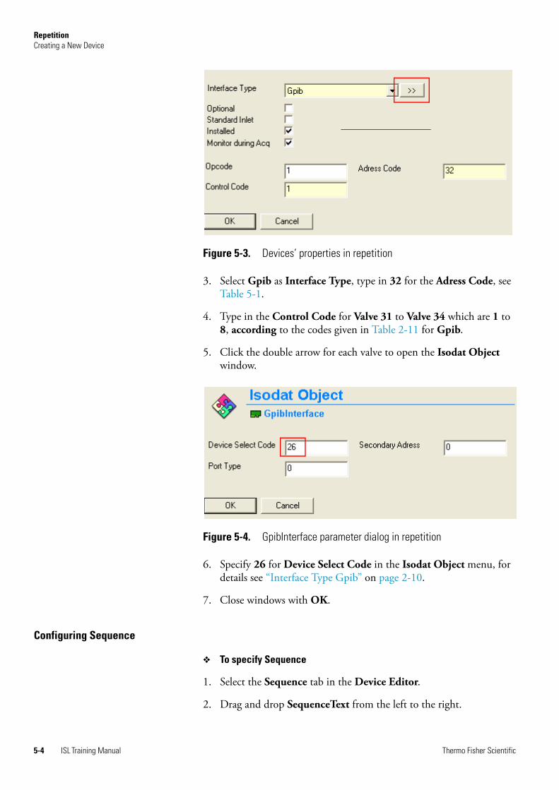
RepetitionCreating a New Device
3. Select Gpib as Interface Type, type in 32 for the Adress Code, see Table 5-1.
4. Type in the Control Code for Valve 31 to Valve 34 which are 1 to 8, according to the codes given in Table 2-11 for Gpib.
5. Click the double arrow for each valve to open the Isodat Object window.
6. Specify 26 for Device Select Code in the Isodat Object menu, for details see “Interface Type Gpib” on page 2-10.
7. Close windows with OK.
Configuring Sequence
❖ To specify Sequence
1. Select the Sequence tab in the Device Editor.
2. Drag and drop SequenceText from the left to the right.
Figure 5-3. Devices’ properties in repetition
Figure 5-4. GpibInterface parameter dialog in repetition
5-4 ISL Training Manual Thermo Fisher Scientific
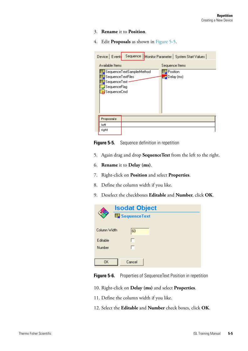
RepetitionCreating a New Device
3. Rename it to Position.
4. Edit Proposals as shown in Figure 5-5.
5. Again drag and drop SequenceText from the left to the right.
6. Rename it to Delay (ms).
7. Right-click on Position and select Properties.
8. Define the column width if you like.
9. Deselect the checkboxes Editable and Number, click OK.
10. Right-click on Delay (ms) and select Properties.
11. Define the column width if you like.
12. Select the Editable and Number check boxes, click OK.
Figure 5-5. Sequence definition in repetition
Figure 5-6. Properties of SequenceText Position in repetition
Thermo Fisher Scientific ISL Training Manual 5-5

RepetitionCreating a New Device
Configuring System Start Values
❖ To specify the System Start Values
1. Select the System Start Values tab in the Device Editor.
2. Drag and drop the valves to the right.
3. For each valve, right-click and select Properties.
4. In the Transfer window, select State Off for Valve 31 and Valve 32.
5. In the Transfer window, select State ON for Valves 33 and Valves 34.
6. Confirm each with OK.
Figure 5-7. Properties of SequenceText Delay (ms) in repetition
Figure 5-8. System Start Values for valves in repetition
5-6 ISL Training Manual Thermo Fisher Scientific

RepetitionSelecting Acqusition Mode
Selecting Acqusition ModeThe acquisition mode is configured in the Isodat Configuration - IsoConfigurator. For a detailed description see “Selecting an Acquisition Mode” on page 2-33.
❖ To configue the acquisition mode
1. Right-click in the left view on Isodat Configuration.iso and click Add Configuration or click the menu Edit > Add Configuration (see Figure 2-2). A New Configuration is added to the left view.
2. Drag and drop My new changeover from the right view to New Configuration in the left below Capillary.
3. Right-click on New Configuration and select Properties.
Figure 5-9. New Configuration in repetition
Thermo Fisher Scientific ISL Training Manual 5-7

RepetitionSelecting Acqusition Mode
4. Select Dual Inlet and confirm with OK.
5. Close the Isodat Configuration - IsoConfigurator.
Creating a New Panel
❖ To create a new panel
1. Create a new Panel as described in “Creating a New Panel” on page 3-2.
Figure 5-10. Acquisition mode settings or My new changeover
5-8 ISL Training Manual Thermo Fisher Scientific

RepetitionCreating the Visualization in the New Panel
Creating the Visualization in the New PanelFor a detailed description on creating a visualization in the Peripheral Visualisatiuon editor, see “Creating a Visualization in the Panel” on page 3-4.
❖ To create the visualization for My new changeover
1. Create a new Panel as described in “Creating a New Panel” on page 3-2.
1. Drag and drop My new changeover@Valve 31, -32, -33 and -34 from the left Available Hardware Parts view into the Peripherals panel (working area). The Peripherals box above the panel will show each item’s description.
2. Drag and drop Visual Object Text to the right, onto the panel.
3. Type in the name for each valve, for example 31, 32, 33, and 34.
Figure 5-11. Peripheral Visualisation editor in repetition
Figure 5-12. Drag Visual Objects Text and Pipe to the panel in repetition
Thermo Fisher Scientific ISL Training Manual 5-9

RepetitionCreating the Visualization in the New Panel
4. Type in the name for each valve, for example 31, 32, 33, and 34.
5. Drag and drop Visual Object Pipe to the right, onto the panel.
6. Connect the Visual Object Pipe to the valves.
7. Repeat until all valves are connected with pipes in the desired way.
Saving the Visualization
For a detailed description, see “Saving the Visualization” on page 3-15.
❖ To save the Peripheral Visualisation file
1. In the PeripheralVisualisation editor, go to File > Save As.
2. Type in a descriptive file name, e.g. My new Cov.
3. Click Save.
Assigning a Visualization Dialog
For a detailed description, see “Assigning a Visualization Dialog” on page 5-10.
❖ To assign a Visualisation Dialog to your device
1. In the Isodat Configuration - IsoConfigurator, right-click on New Configuration.
2. Select Visualisation Dialogs to open the Visualisation Dialogs window.
Figure 5-13. Visualization complete in repetition
5-10 ISL Training Manual Thermo Fisher Scientific

RepetitionCreating the Visualization in the New Panel
3. Drag and drop My new Cov into the right View Dialog view.
4. Close the Isodat Configuration - IsoConfigurator.
Figure 5-14. Assign Visualisation Dialog in repetition
Thermo Fisher Scientific ISL Training Manual 5-11
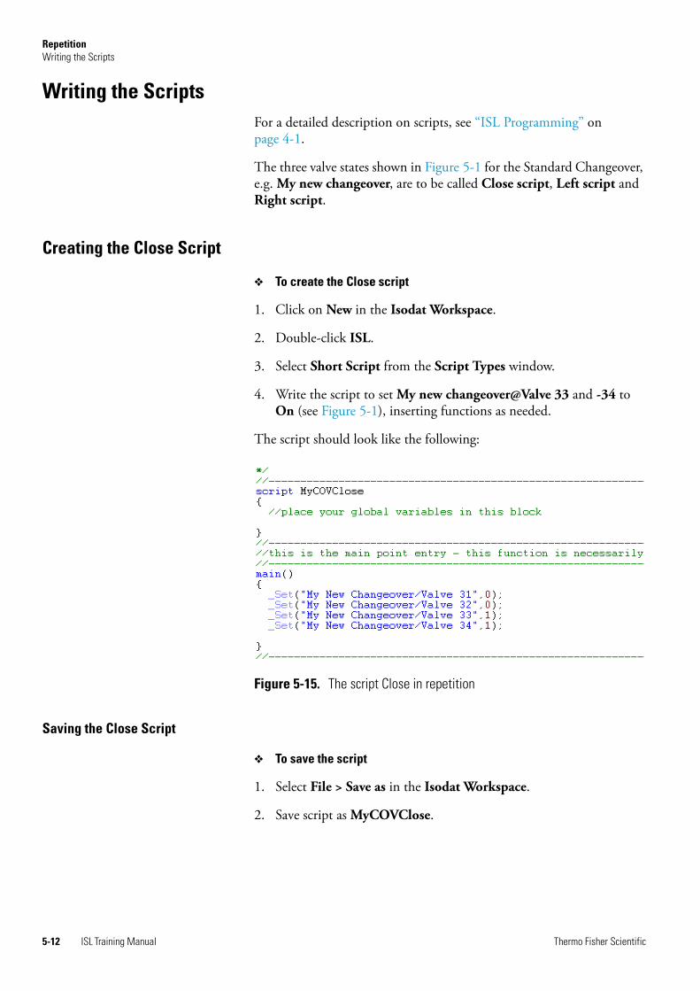
RepetitionWriting the Scripts
Writing the ScriptsFor a detailed description on scripts, see “ISL Programming” on page 4-1.
The three valve states shown in Figure 5-1 for the Standard Changeover, e.g. My new changeover, are to be called Close script, Left script and Right script.
Creating the Close Script
❖ To create the Close script
1. Click on New in the Isodat Workspace.
2. Double-click ISL.
3. Select Short Script from the Script Types window.
4. Write the script to set My new changeover@Valve 33 and -34 to On (see Figure 5-1), inserting functions as needed.
The script should look like the following:
Saving the Close Script
❖ To save the script
1. Select File > Save as in the Isodat Workspace.
2. Save script as MyCOVClose.
Figure 5-15. The script Close in repetition
5-12 ISL Training Manual Thermo Fisher Scientific

RepetitionWriting the Scripts
Creating the Left Script
❖ To create the Left script
1. Click on New in the Isodat Workspace.
2. Double-click ISL.
3. Select Short Script from the Script Types window.
4. Write the script to set My new changeover@Valve 31 and -34 to On (see Figure 5-1), using functions as needed.
The script should look like the following:
Saving the Left Script
❖ To save the script
1. Select File > Save as in the Isodat Workspace.
2. Save script as CovLt.
Creating the Right Script
❖ To create the Right script
1. Click on New in the Isodat Workspace.
2. Double-click ISL.
3. Select Short Script from the Script Types window.
4. Write the script to set My new changeover@Valve 32 and -33 to On (see Figure 5-1), using functions as needed.
Figure 5-16. The script Left in repetition
Thermo Fisher Scientific ISL Training Manual 5-13

RepetitionWriting the Scripts
The script should look like the following:
Saving the Right Script
❖ To save the script
1. Select File > Save as in the Isodat Workspace.
2. Save script as CovRt.
Figure 5-17. The script Right in repetition
5-14 ISL Training Manual Thermo Fisher Scientific

RepetitionAssigning the Scripts to the Valves
Assigning the Scripts to the ValvesThe scripts are to be assigned in the following way:
• Valve 31: assign CovLt
• Valve 32: assign CovRt
• Valve 33: assign MyCOVClose
• Valve 34: assign MyCOVClose
❖ To assign the scripts to the valves
1. Select File > Open in the Isodat Workspace.
2. Open the file My new Cov.Peripheral Visualisation.
3. Double-click on Valve 31 to open the corresponding Properties dialog.
4. Select the ISL script CovLt in the field Script Name to apply it to this valve.
5. Double-click on Valve 32, and in the Properties dialog, select CovRt in the field Script Name to apply it to the valve.
6. Double-click on Valve 33, and in the Properties dialog, select MyCOVClose in the field Script Name to apply it to the valve. Repeat for Valve 34.
7. For each valve, additionally select the check box Show script Marker to visualize that you have put a script behind an item.
Figure 5-18. Assigning script to valve in repetition
Thermo Fisher Scientific ISL Training Manual 5-15

RepetitionAssigning the Scripts to the Valves
The script marker red, curly brackets appear in the visualization:
8. Click Save. The Peripheral Visualisation file My new Cov will automatically be saved in Thermo\Isodat NT\Global\Dynamic Devices.
Figure 5-19. PeripheralVisualisation editor script markers in repetition
5-16 ISL Training Manual Thermo Fisher Scientific

RepetitionTesting the Scripts
Testing the Scripts❖ To test the scripts
1. Open the Isodat folder and select Acquisition.
2. Select your New Configuration from the list of hardware configurations.
3. Open the window of your Peripheral Visualisation file My new Cov.
4. Click on each valve to test the functionality of the scripts.
Figure 5-20. Isodat folder
Figure 5-21. Repetition test run of MyCOVClose
Thermo Fisher Scientific ISL Training Manual 5-17

RepetitionTesting the Scripts
Figure 5-22. Repetition test run of CovLt
Figure 5-23. Repetition test run of CovRt
5-18 ISL Training Manual Thermo Fisher Scientific

Glossary
This section lists and defines terms used in this manual. It also includes acronyms, metric prefixes, symbols, and abbreviations.
A
A ampere
ac alternating current
ADC analog-to-digital converter
AP acquisition processor
API atmospheric pressure ionization
ASCII American Standard Code for Information Interchange
B
b bit
B byte (8 b)
baud rate data transmission speed in events per second
C
°C degrees Celsius
cfm cubic feet per minute
CI chemical ionization
CID collision-induced dissociation
cm centimeter
cm3 cubic centimeter
Continuous-Flow (CF) Automated preparation device and mass spectrometer in which sample analysis is conducted in a continuous stream of helium carrier gas.
CPU central processing unit (of a computer)
CRC cyclic redundancy check
CRM consecutive reaction monitoring
<Ctrl> control key on the terminal keyboard
D
d depth
Da dalton
DAC digital-to-analog converter
dc direct current
driver A device-specific control program that enables a computer to work with a particular device.
DS data system
DSP digital signal processor
Dual Inlet (DI) Inlet method in which a pure gas sample is admitted into an isotope ratio mass spectrometer (IRMS) by a variable volume bellows. A reference gas is admitted into the IRMS via a second variable volume bellows. The bellows are balanced to provide sample and reference signal responses of equal intensity.
E
EI electron ionization
Elemental Analyzer (EA) Automated sample preparation instrument in which samples are automatically converted into pure gases for isotope ratio analysis. An elemental analyzer contains the
A B C D E F G H I J K L M N O P Q R S T U V W X Y Z
Thermo Fisher Scientific ISL Training Manual G-1

Glossary: EMBL – LAN
following elements: (i) furnace for combustion, reduction or pyrolysis of sample material; (ii) chemical traps for analyte gas purification; (iii) gas chromatography for time separation of these analyte gases.
EMBL European Molecular Biology Laboratory
<Enter> Enter key on the terminal keyboard
ESD electrostatic discharge
ESI electrospray ionization
eV electron volt
F
f femto (10-15)
°F degrees Fahrenheit
forepump The pump that evacuates the foreline. A rotary-vane pump is a type of forepump.
ft foot
FTP file transfer protocol
FWHM Full Width at Half Maximum
G
g gram
G Gauss; giga (109)
GC gas chromatograph; gas chromatography
GC/MS gas chromatograph / mass spectrometer
GISP Greenland Ice Sheet Precipitation. International reference standard for hydrogen and oxygen isotopes.
See also SLAP and VSMOW.
GUI graphical user interface
H
h hour
h height
HPLC High Performance Liquid Chromatography. Standalone liquid chromatography system (or inlet for mass spectrometry detector).
HV high voltage
Hz hertz (cycles per second)
I
IAEA International Atomic Energy Agency
ICIS™ Interactive Chemical Information System
ICL™ Instrument Control Language™
ICP inductively coupled plasma
ICP-OES inductively coupled plasma optical emission spectroscopy
ID inside diameter
IEC International Electrotechnical Commission
IEEE Institute of Electrical and Electronics Engineers
in. inch
I/O input/output
ion optics Focuses and transmits ions from the ion source to the mass analyzer.
ion source A device that converts samples to gas-phase ions.
IRMS isotope ratio mass spectrometer
K
k kilo (103, 1000)
K kilo (210, 1024)
KEGG Kyoto Encyclopedia of Genes and Genomes
kg kilogram
L
l length
L liter
LAN local area network
G-2 ISL Training Manual Thermo Fisher Scientific

Glossary: lb – RF
lb pound
LC Liquid chromatography. A process that separates a chemical mixture carried by liquid into components as a result of differential distribution of the solutes as they flow around or over a stationary or solid phase.
LC/MS liquid chromatograph / mass spectrometer
LED light-emitting diode
log file A text file, with a .log file extension, that is used to store lists of information.
μ micro (10-6)
M
m meter
m milli (10-3)
M mega (106)
M+ molecular ion
MB Megabyte (1 048 576 bytes)
MH+ protonated molecular ion
min minute
mL milliliter
mm millimeter
MS mass spectrometer; mass spectrometry
MS MSn power: where n = 1
MS/MS MSn power: where n = 2
MSn MSn power: where n = 1 through 10
m/z Mass-to-charge ratio. An abbreviation used to denote the quantity formed by dividing the mass of an ion (in u) by the number of charges carried by the ion. For example, for the ion C7H7
2+, m/z = 45.5.
N
n nano (10-9)
Natural Abundance The concentration of isotopes as found in nature.
NCBI National Center for Biotechnology Information (USA)
NIST National Institute of Standards and Technology (USA)
noise Any random disturbance that obscures the clarity of a signal.
O
OD outside diameter
Ω ohm
outlier A calibration data point that does not appear to correlate to other calibration data points within experimental error.
P
p pico (10-12)
Pa pascal
PCB printed circuit board
PE protective earth
PID proportional / integral / differential
P/N part number
P/P peak-to-peak voltage
ppm parts per million
psig pounds per square inch, gauge
R
RAM random access memory
relative standard deviation A measure of the dispersion of a group of measurements relative to the mean of the group. Relative standard deviation is expressed as a percentage of the average value. The percent relative standard deviation is calculated
as:%RSD = 100 (S / )
where S is the standard deviation and is the sample mean.
RF radio frequency
Thermo Fisher Scientific ISL Training Manual G-3

Glossary: RMS – WEEE
RMS root mean square
ROM read-only memory
rotary-vane pump A mechanical vacuum pump that establishes the vacuum necessary for the proper operation of the turbomolecular pump. (Also called a roughing pump or forepump.)
RS-232 An accepted industry standard for serial communication connections. This Recommended Standard (RS) defines the specific lines and signal characteristics used by serial communications controllers to standardize the transmission of serial data between devices.
S
s second
serial port An input/output location (channel) for serial data transmission.
SIM selected ion monitoring
SLAP Standard Light Antarctic Precipitation; international reference standard for hydrogen and oxygen isotopes.
See also VSMOW.
SRM selected reaction monitoring
standard deviation In statistics, the standard deviation is a measure of the dispersion of a group of measurements. For example, masses, times, or intensities. Standard deviation is calculated as follows:
where Var (Xi...XN) is the variance.
See also relative standard deviation.
T
TCP/IP transmission control protocol / Internet protocol
TIC total ion current
Torr A unit of pressure, equal to 1 mm of mercury and 133.32 Pa.
turbomolecular pump A vacuum pump that provides a high vacuum for the mass spectrometer and detector system.
U
u atomic mass unit
UHV ultra high vacuum
V
V volt
V ac volts alternating current
V dc volts direct current
vol volume
VCDT Vienna Canyon Diablo Troilite; international reference standard for sulfur isotopes.
VPDB Vienna Pee Dee Belemnite; international reference standard for carbon and oxygen isotopes.
VSMOW Vienna Standard Mean Ocean Water; international reference standard for hydrogen and oxygen isotopes.
See also SLAP.
W
w width
W watt
WEEE European Union Waste Electrical and Electronic Equipment Directive. Provides guidelines for disposal of electronic waste.
G-4 ISL Training Manual Thermo Fisher Scientific


Thermo Fisher Scientific Inc.
81 Wyman Street
P.O. Box 9046
Waltham, Massachussetts 02454-9046
United States
www.thermo.com
Part of Thermo Fisher Scientific