
ISIS Second Target Station Project Summary Target design, analysis and optimisation Robbie Scott...
22
ISIS Second Target Station Project Summary Target design, analysis and optimisation Robbie Scott Mechanical Design / Project Engineer ISIS Facility
-
Upload
cecily-franklin -
Category
Documents
-
view
217 -
download
0
Transcript of ISIS Second Target Station Project Summary Target design, analysis and optimisation Robbie Scott...

ISIS Second Target Station
Project Summary
Target design, analysis and optimisation
Robbie Scott
Mechanical Design / Project Engineer
ISIS Facility

• Upgrade of ISIS – accelerator based,
pulsed neutron source
• Synchrotron accelerator shared
between both target stations
• Double the number of instruments
ISIS Second Target Station
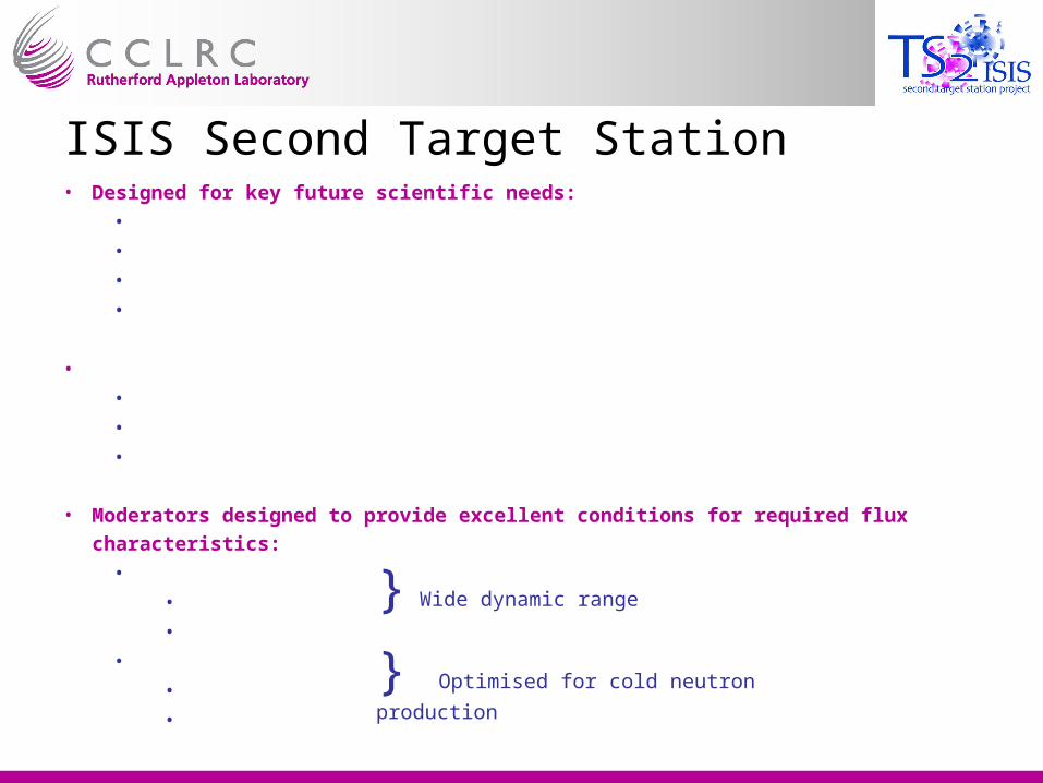
• Designed for key future scientific needs:
•
Soft matter
•
Advanced materials
•
Bio-molecular science
•
Nano-technology
•
Scientific requirements imply need for specific flux characteristics:
•
Significantly enhanced cold neutron flux
•
Broad spectral range
•
High resolution
• Moderators designed to provide excellent conditions for required flux characteristics:
•
Low frequency :
•
10Hz
•
100ms frame
•
Low power:
•
48kW
•
60µA
ISIS Second Target Station
} Wide dynamic range
} Optimised for cold neutron production


• Maximise use of ‘target’ materials
• Design target geometry to match proton beam
• Maximises target neutron yield, while minimising absorption
• Optimise cross-sectional area
• Minimise volume of coolant channels
• Maximises solid angle which moderators view
Neutronically efficient target design
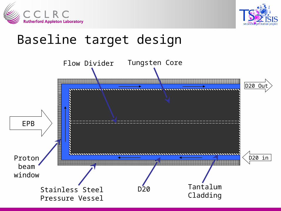
Baseline target design
EPB
D20 Out
D20 in
Stainless Steel Pressure Vessel
D20 Tantalum Cladding
Flow Divider Tungsten Core
Proton beam
window
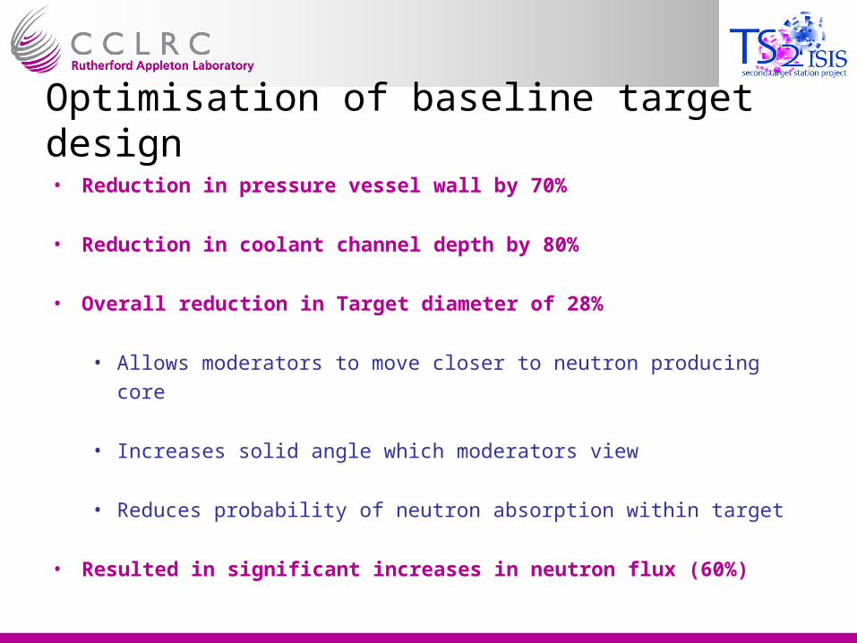
Optimisation of baseline target design
• Reduction in pressure vessel wall by 70%
• Reduction in coolant channel depth by 80%
• Overall reduction in Target diameter of 28%
• Allows moderators to move closer to neutron producing core
• Increases solid angle which moderators view
• Reduces probability of neutron absorption within target
• Resulted in significant increases in neutron flux (60%)

Back to the drawing board!• Removal of proton beam window & introduction of new cooling channel concept
• Proton beam no longer passes through Inconel window and D20
• Flow channel geometry altered – purely radial cooling
• Flux increase of approximately 5%
• Improved reliability
Pressure distribution within target cooling channels


Materials• Pressure vessel material choice
• Replace stainless steel with Tantalum
• Further reductions in target diameter (now 63% of original size)
• Further 15% flux increase

Consequences of design alterations
• Total predicted flux increase due to design alterations ≈ 75 - 80%
• Neutron flux 95% of pure Tungsten target
• However new cooling channel concept must be proven
• Computational Fluid Dynamics (CFD) employed for analysis and
optimisation of coolant channels
• CFD subsequently verified using flow tests

CFD Analysis of initial design• CFX used to Computational Fluid Dynamics analysis
• CFD revealed problematic separation & pressure drop at inside of bend
• Resulting recirculation would heat coolant excessively

Removal of recirculation•A solution was required to
remove the recirculation
•The flow guide was
modified into an aerofoil
form
• Prevents separation and
subsequent recirculation

Cavitation• A fluid’s vapour pressure is
proportional to temperature
• If the pressure within a flow falls
below the local vapour pressure,
cavities (or bubbles) will form
• As the cavities leave the low
pressure region, they collapse,
damaging the vessel wall2.4 bar
1
0
-0.7

Pre
ssu
re [
Pa]
Vapour Pressure H20

Cavitation Prevention• High flow velocities within the target cause
a pressure drop on the inside of the bend
• If local vapour pressure is greater than local pressure, cavitation will occur
• Solution
• Map vapour pressure onto flow model
• Increase inlet and outlet pressures (maintaining differential) until pressure in all regions are above local vapour pressure
• Final inlet pressure 5 bar
[K]
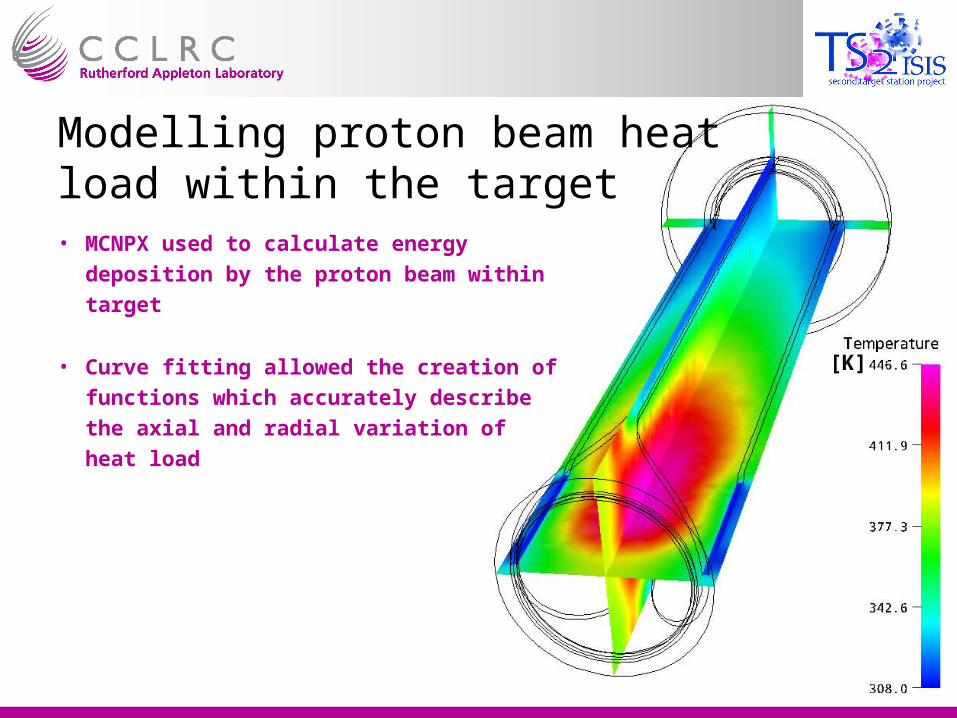
Modelling proton beam heat load within the target• MCNPX used to calculate energy deposition by
the proton beam within target
• Curve fitting allowed the creation of functions
which accurately describe the axial and radial
variation of heat load

Thermally induced stress• Temperatures within target are calculated using CFD
• Temperatures exported to an FEA package (ANSYS)
• Thermally induced expansions are then calculated
• Resultant stresses and are then calculated
• Differing coefficient of thermal expansion
• Tungsten & Tantalum differ by 2µm/m/°C
• Small stresses

Verifying CFD Results• Prototype thermal test target, installed with a dense network of pressure
tappings
• 5 cartridge heaters will supply 37kW of power, to test the cooling
• Power varied axially along the target

Manufacturing• Majority of target simple to manufacture:
• Tungsten core is encased in a 1mm sleeve of Tantalum
• Sleeve is e-beam welded, creating a hermetic seal
• Assembly is hot isostatically pressed (HIP)
• Ultrasonic NDT used to test HIP bond

• Tantalum pressure vessel complex to manufacture
• Incorporates aerofoil structures on ID!
• Former created on CNC mill
• Hot Isostatic Pressing is used to create the vessel from powder
• Former leached away after vessel created
• Pressure vessel shrink fitted onto core, then assembly e-beam welded

Project Uncertainties
• Potential for erosion due to high coolant velocities
• Pressure vessel manufacturing method yet to be proven