Isilon OneFS Version 7.0 Administration Guide
320
Isilon OneFS Version 7.0 Administration Guide
description
Isilon
Transcript of Isilon OneFS Version 7.0 Administration Guide
IsilonOneFSVersion 7.0
Administration Guide

Published November, 2012
Copyright © 2001 - 2012 EMC Corporation. All rights reserved.
EMC believes the information in this publication is accurate as of its publication date. The information is subject to changewithout notice.
The information in this publication is provided as is. EMC Corporation makes no representations or warranties of any kind withrespect to the information in this publication, and specifically disclaims implied warranties of merchantability or fitness for aparticular purpose. Use, copying, and distribution of any EMC software described in this publication requires an applicablesoftware license.
EMC², EMC, and the EMC logo are registered trademarks or trademarks of EMC Corporation in the United States and othercountries. All other trademarks used herein are the property of their respective owners.
For the most up-to-date product documentation, go to the Isilon Customer Support Center.
EMC CorporationHopkinton, Massachusetts 01748-91031-508-435-1000 In North America 1-866-464-7381www.EMC.com
2 OneFS 7.0 Administration Guide

Introduction to Isilon scale-out NAS 15
Architecture..................................................................................................16Isilon Node....................................................................................................16Internal and external networks......................................................................17Isilon cluster.................................................................................................17
Cluster administration............................................................................17Quorum..................................................................................................17Splitting and merging.............................................................................18Storage pools.........................................................................................18IP address pools.....................................................................................19
The OneFS operating system.........................................................................19Data-access protocols............................................................................19Identity management and access control................................................20
Structure of the file system............................................................................21Data layout.............................................................................................21Writing files............................................................................................21Reading files...........................................................................................22Metadata layout.....................................................................................22Locks and concurrency...........................................................................22Striping..................................................................................................22
Data protection overview...............................................................................23N+M data protection...............................................................................24Data mirroring........................................................................................24The file system journal............................................................................25Virtual hot spare.....................................................................................25Balancing protection with storage space.................................................25
VMware integration.......................................................................................25The iSCSI option............................................................................................25Software modules.........................................................................................26
Authentication and access control 27
Data access control.......................................................................................29ACLs.......................................................................................................29UNIX permissions...................................................................................30Mixed-permission environments.............................................................30
Roles and privileges......................................................................................31Built-in roles...........................................................................................31OneFS privileges.....................................................................................32
Authentication..............................................................................................34Local provider.........................................................................................34File provider............................................................................................34Active Directory.......................................................................................35LDAP.......................................................................................................35NIS.........................................................................................................35Authentication provider features.............................................................36
Identity management....................................................................................36Identity types..........................................................................................36Access tokens........................................................................................37ID mapping.............................................................................................38
Chapter 1
Chapter 2
CONTENTS
OneFS 7.0 Administration Guide 3

On-disk identity selection.......................................................................39User mapping across identities...............................................................40Configuring user mapping.......................................................................40Well-known security identifiers...............................................................41
Access zones................................................................................................41Home directories...........................................................................................42
Home directory creation through SMB.....................................................42Home directory creation through SSH and FTP.........................................42Home directory creation in mixed environments.....................................43Default home directory settings in authentication providers....................44Supported expansion variables..............................................................44
Managing access permissions.......................................................................45Configure access management settings..................................................45Modify ACL policy settings......................................................................46Update cluster permissions....................................................................51
Managing roles.............................................................................................52View roles...............................................................................................52Create a custom role...............................................................................53Modify a role...........................................................................................53Delete a custom role...............................................................................53
Create a local user.........................................................................................53Create a local group......................................................................................54Managing users and groups..........................................................................55
Modify a local user.................................................................................55Modify a local group...............................................................................55Delete a local user..................................................................................56Delete a local group................................................................................56
Creating file providers...................................................................................56Create a file provider...............................................................................56Generate a password file........................................................................57
Managing file providers.................................................................................57Modify a file provider..............................................................................57Delete a file provider...............................................................................58Password file format...............................................................................58Group file format....................................................................................59Netgroup file format................................................................................59
Create an Active Directory provider................................................................59Managing Active Directory providers..............................................................60
Modify an Active Directory provider.........................................................60Delete an Active Directory provider.........................................................60Configure Kerberos settings....................................................................60Active Directory provider settings............................................................61
Create an LDAP provider................................................................................62Managing LDAP providers..............................................................................65
Modify an LDAP provider.........................................................................65Delete an LDAP provider.........................................................................65
Create a NIS provider.....................................................................................65Managing NIS providers................................................................................66
Modify a NIS provider.............................................................................66Delete a NIS provider..............................................................................67
Create an access zone...................................................................................67Managing access zones................................................................................68
Modify an access zone............................................................................68Associate an IP address pool with an access zone..................................69Delete an access zone............................................................................69
CONTENTS
4 OneFS 7.0 Administration Guide

File sharing 71
NFS...............................................................................................................72SMB..............................................................................................................72HTTP..............................................................................................................72FTP................................................................................................................73Mixed protocol environments........................................................................73Write caching with SmartCache.....................................................................73
Write caching for asynchronous writes....................................................74Write caching for synchronous writes......................................................74
Create an NFS export.....................................................................................75Create an SMB share.....................................................................................75Configure NFS file sharing.............................................................................76
Disable NFS file sharing..........................................................................77NFS service settings................................................................................77NFS export behavior settings..................................................................78NFS performance settings.......................................................................78NFS client compatibility settings.............................................................80
Configure SMB file sharing............................................................................80File and directory permission settings.....................................................81Disable SMB file sharing.........................................................................81Snapshots settings directory..................................................................82SMB performance settings......................................................................82SMB security settings.............................................................................83
Configure and enable HTTP file sharing..........................................................83Configure and enable FTP file sharing............................................................84Managing NFS exports...................................................................................84
Modify an NFS export..............................................................................85Delete an NFS export..............................................................................85View and configure default NFS export settings.......................................85
Managing SMB shares...................................................................................86Add a user or group to an SMB share......................................................86Modify an SMB share..............................................................................86Delete an SMB share..............................................................................87SMB share settings.................................................................................87View and modify SMB share settings......................................................88
Snapshots 89
Data protection with SnapshotIQ...................................................................90Snapshot disk-space usage..........................................................................90Snapshot schedules......................................................................................91Snapshot aliases..........................................................................................91File and directory restoration.........................................................................91File clones.....................................................................................................91
File clones considerations......................................................................92iSCSI LUN clones....................................................................................93
Snapshot locks.............................................................................................93Snapshot reserve..........................................................................................93SnapshotIQ license functionality...................................................................93Creating snapshots with SnapshotIQ.............................................................94
Create a SnapRevert domain...................................................................94Create a snapshot...................................................................................95Create a snapshot schedule....................................................................95Snapshot naming patterns......................................................................96
Managing snapshots ....................................................................................99
Chapter 3
Chapter 4
CONTENTS
OneFS 7.0 Administration Guide 5

Reducing snapshot disk-space usage.....................................................99Delete snapshots..................................................................................100Modify a snapshot................................................................................101Modify a snapshot alias........................................................................101View snapshots....................................................................................101Snapshot information...........................................................................101
Restoring snapshot data.............................................................................102Revert a snapshot.................................................................................102Restore a file or directory using Windows Explorer................................102Restore a file or directory through a UNIX command line.......................103Clone a file from a snapshot.................................................................103
Managing snapshot schedules....................................................................103Modify a snapshot schedule.................................................................103Delete a snapshot schedule..................................................................104View snapshot schedules.....................................................................104
Managing with snapshot locks....................................................................104Create a snapshot lock.........................................................................104Modify a snapshot lock.........................................................................105Delete a snapshot lock.........................................................................105Snapshot lock information....................................................................105
Configure SnapshotIQ settings....................................................................106SnapshotIQ settings.............................................................................106
Set the snapshot reserve.............................................................................107
Data replication with SyncIQ 109
Replication policies and jobs......................................................................110Source and target cluster association...................................................111Full and differential replication.............................................................111Controlling replication job resource consumption.................................111Replication reports...............................................................................112
Replication snapshots.................................................................................112Source cluster snapshots.....................................................................112Target cluster snapshots.......................................................................113
Data failover and failback with SyncIQ.........................................................113Data failover.........................................................................................114Data failback........................................................................................114
Recovery times and objectives for SyncIQ....................................................114SyncIQ license functionality........................................................................115Creating replication policies........................................................................115
Excluding directories in replication.......................................................115Excluding files in replication.................................................................116File criteria options...............................................................................117Configure default replication policy settings.........................................118Create a replication policy....................................................................119Create a SyncIQ domain........................................................................123Assess a replication policy....................................................................124
Managing replication to remote clusters......................................................124Start a replication job...........................................................................124Pause a replication job.........................................................................124Resume a replication job......................................................................125Cancel a replication job........................................................................125View active replication jobs..................................................................125View replication performance information............................................125Replication job information..................................................................125
Initiating data failover and failback with SyncIQ..........................................126
Chapter 5
CONTENTS
6 OneFS 7.0 Administration Guide

Fail over data to a secondary cluster.....................................................126Fail over SmartLock directories.............................................................127Failover revert.......................................................................................127Fail back data to a primary cluster........................................................128Prepare SmartLock directories for failback............................................128Fail back SmartLock directories............................................................129
Managing replication policies.....................................................................130Modify a replication policy....................................................................130Delete a replication policy....................................................................130Enable or disable a replication policy...................................................130View replication policies.......................................................................131Replication policy information..............................................................131Replication policy settings....................................................................131
Managing replication to the local cluster.....................................................133Cancel replication to the local cluster...................................................133Break local target association...............................................................133View replication jobs targeting the local cluster....................................134Remote replication policy information...................................................134
Managing replication performance rules.....................................................134Create a network traffic rule..................................................................134Create a file operations rule..................................................................135Modify a performance rule....................................................................135Delete a performance rule.....................................................................135Enable or disable a performance rule....................................................136View performance rules........................................................................136
Managing replication reports.......................................................................136Configure default replication report settings.........................................136Delete replication reports.....................................................................136View replication reports........................................................................137Replication report information..............................................................137
Managing failed replication jobs.................................................................138Resolve a replication policy..................................................................138Reset a replication policy......................................................................138Perform a full or differential replication.................................................139
Data layout with FlexProtect 141
File striping.................................................................................................142Data protection levels.................................................................................142FlexProtect data recovery.............................................................................142
Smartfail...............................................................................................143Node failures........................................................................................143
Managing protection levels.........................................................................144Data protection level information................................................................144Data protection level disk space usage.......................................................145
NDMP backup 147
NDMP two way backup................................................................................148NDMP protocol support...............................................................................148Supported DMAs.........................................................................................148NDMP hardware support.............................................................................149NDMP backup limitations............................................................................149NDMP performance recommendations........................................................149Excluding files and directories from NDMP backups....................................151Configuring basic NDMP backup settings....................................................152
Chapter 6
Chapter 7
CONTENTS
OneFS 7.0 Administration Guide 7

Configure and enable NDMP backup.....................................................152Disable NDMP backup..........................................................................153View NDMP backup settings.................................................................153NDMP backup settings..........................................................................153
Create an NDMP user account.....................................................................153Managing NDMP user accounts...................................................................154
Modify the password of an NDMP user account.....................................154Delete an NDMP user account...............................................................154View NDMP user accounts....................................................................154
Managing NDMP backup devices.................................................................154Detect NDMP backup devices...............................................................154Modify an NDMP backup device name..................................................155Delete a device entry for a disconnected NDMP backup device.............155View NDMP backup devices..................................................................155NDMP backup device settings...............................................................156
Managing NDMP backup ports....................................................................156Modify NDMP backup port settings.......................................................156Enable or disable an NDMP backup port...............................................156View NDMP backup ports......................................................................157NDMP backup port settings..................................................................157
Managing NDMP backup sessions...............................................................157Terminate an NDMP session.................................................................157View NDMP sessions............................................................................158NDMP session information...................................................................158
View NDMP backup logs..............................................................................159NDMP environment variables......................................................................159
File retention with SmartLock 163
SmartLock operation modes........................................................................164Enterprise mode...................................................................................164Compliance mode.................................................................................164
Replication and backup with SmartLock......................................................165Data replication in compliance mode....................................................165Data replication and backup in enterprise mode...................................165
SmartLock license functionality...................................................................166SmartLock best practices and considerations..............................................166Set the compliance clock............................................................................167View the compliance clock..........................................................................168Creating a SmartLock directory....................................................................168
Retention periods.................................................................................168Autocommit time periods.....................................................................168Create a SmartLock directory................................................................169
Managing SmartLock directories.................................................................170Modify a SmartLock directory................................................................170View SmartLock directory settings........................................................170SmartLock directory configuration settings...........................................170
Managing files in SmartLock directories......................................................171Set a retention period through a UNIX command line............................172Set a retention period through Windows Powershell.............................172Commit a file to a WORM state through a UNIX command line...............172Commit a file to a WORM state through Windows Explorer....................173Override the retention period for all files in a SmartLock directory.........173Delete a file committed to a WORM state .............................................174View WORM status of a file...................................................................174
Chapter 8
CONTENTS
8 OneFS 7.0 Administration Guide

Protection domains 175
Protection domain considerations...............................................................176Create a protection domain.........................................................................176Delete a protection domain.........................................................................176View protection domains.............................................................................177Protection domain types.............................................................................177
Cluster administration 179
User interfaces............................................................................................180Web administration interface................................................................180Command-line interface .......................................................................180Node front panel...................................................................................180OneFS Platform API...............................................................................181
Connecting to the cluster.............................................................................181Log in to the web administration interface............................................181Open an SSH connection to a cluster....................................................181Restart or shut down the cluster...........................................................181
Licensing....................................................................................................182Activating licenses................................................................................182Activate a license through the web administration interface.................182Activate a license through the command-line interface.........................183View license information......................................................................183Unconfiguring licenses.........................................................................183Unconfigure a license...........................................................................184
General cluster settings...............................................................................184Configuring the cluster date and time...................................................184Set the cluster date and time................................................................185Specify an NTP time server....................................................................185Set the cluster name.............................................................................186Specify contact information..................................................................186View SNMP settings..............................................................................186Configure SMTP email settings..............................................................186Configuring SupportIQ..........................................................................187Enable and configure SupportIQ...........................................................187Disable SupportIQ................................................................................188Enable or disable access time tracking.................................................188Specify the cluster join mode................................................................188Specify the cluster character encoding..................................................188
Cluster statistics.........................................................................................189Performance monitoring..............................................................................189Cluster monitoring.......................................................................................189
Monitor the cluster...............................................................................190View node status..................................................................................191Events and notifications.......................................................................191
Monitoring cluster hardware........................................................................196View node hardware status...................................................................196SNMP monitoring..................................................................................197
Cluster maintenance...................................................................................199Replacing node components.................................................................199Managing cluster nodes.......................................................................200
Remote support using SupportIQ.................................................................201SupportIQ scripts..................................................................................202
Upgrading OneFS........................................................................................203Cluster join modes......................................................................................204
Chapter 9
Chapter 10
CONTENTS
OneFS 7.0 Administration Guide 9

Event notification settings...........................................................................204System job management.............................................................................205
Job engine overview..............................................................................205Job performance impact........................................................................207Job impact policies...............................................................................207Job priorities.........................................................................................208Managing system jobs..........................................................................208Monitoring system jobs........................................................................211Creating impact policies.......................................................................211Managing impact policies.....................................................................212
SmartQuotas 215
Quotas overview.........................................................................................216Quota types..........................................................................................216Usage accounting and limits.................................................................218Disk-usage calculations........................................................................219Quota notifications...............................................................................220Quota notification rules........................................................................221Quota reports.......................................................................................221
Creating quotas...........................................................................................222Create an accounting quota..................................................................222Create an enforcement quota................................................................223
Managing quotas........................................................................................223Search for quotas.................................................................................224Manage quotas.....................................................................................224Export a quota configuration file...........................................................225Import a quota configuration file...........................................................225
Managing quota notifications......................................................................226Configure default quota notification settings........................................226Configure custom quota notification rules.............................................227Map an email notification rule for a quota.............................................228Configure a custom email quota notification template..........................228
Managing quota reports..............................................................................229Create a quota report schedule.............................................................229Generate a quota report........................................................................229Locate a quota report............................................................................230
Basic quota settings....................................................................................230Advisory limit quota notification rules settings............................................231Soft limit quota notification rules settings...................................................232Hard limit quota notification rules settings..................................................233Limit notification settings............................................................................233Quota report settings..................................................................................234Custom email notification template variable descriptions...........................235
Storage pools 237
Storage pool overview.................................................................................238Autoprovisioning.........................................................................................238Virtual hot spare and SmartPools................................................................239Spillover and SmartPools............................................................................239Node pools.................................................................................................240
Add or move node pools in a tier..........................................................240Change the name or protection level of a node pool..............................240
SSD pools...................................................................................................241File pools with SmartPools..........................................................................241
Chapter 11
Chapter 12
CONTENTS
10 OneFS 7.0 Administration Guide

Tiers............................................................................................................242Create a tier..........................................................................................242Rename a tier.......................................................................................242Delete a tier..........................................................................................243
File pool policies.........................................................................................243Pool monitoring...........................................................................................243
Monitor node pools and tiers................................................................244View unhealthy subpools......................................................................244
Creating file pool policies with SmartPools..................................................244Managing file pool policies.........................................................................245
Configure default file pool policy settings.............................................245Configure default file pool protection settings.......................................246Configure default I/O optimization settings..........................................246Modify a file pool policy........................................................................246Copy a file pool policy...........................................................................247Prioritize a file pool policy.....................................................................247Use a file pool template policy..............................................................247Delete a file pool policy........................................................................248
SmartPools settings....................................................................................248Default file pool protection settings.............................................................250Default file pool I/IO optimization settings..................................................252
Networking 253
Cluster internal network overview................................................................254Internal IP address ranges....................................................................254Cluster internal network failover...........................................................254
External client network overview.................................................................254External network settings......................................................................255IP address pools...................................................................................255Connection balancing with SmartConnect.............................................256External IP failover................................................................................257NIC aggregation....................................................................................257VLANs...................................................................................................258DNS name resolution............................................................................258IPv6 support.........................................................................................258
Configuring the internal cluster network......................................................259Modify the internal IP address range.....................................................259Modify the internal network netmask....................................................259Configure and enable an internal failover network................................260Disable internal network failover..........................................................261
Configuring an external network..................................................................261Adding a subnet...................................................................................261Managing external client subnets.........................................................266Managing IP address pools...................................................................268Managing IP address pool interface members.......................................271Configure DNS settings.........................................................................274
Managing external client connections with SmartConnect...........................275Configure client connection balancing..................................................275Client connection settings....................................................................276
Managing network interface provisioning rules............................................276Create a node provisioning rule............................................................277Modify a node provisioning rule............................................................278Delete a node provisioning rule............................................................278
Chapter 13
CONTENTS
OneFS 7.0 Administration Guide 11
Hadoop 279
Hadoop support overview...........................................................................280Hadoop cluster integration..........................................................................280Managing HDFS...........................................................................................280Configure the HDFS protocol........................................................................280Create a local user.......................................................................................282Enable or disable the HDFS service..............................................................282
Antivirus 283
On-access scanning....................................................................................284Antivirus policy scanning............................................................................284Individual file scanning...............................................................................284Antivirus scan reports.................................................................................285ICAP servers................................................................................................285Supported ICAP servers...............................................................................285Anitvirus threat responses...........................................................................286Configuring global antivirus settings...........................................................287
Exclude files from antivirus scans.........................................................287Configure on-access scanning settings.................................................288Configure antivirus threat response settings.........................................288Configure antivirus report retention settings.........................................288Enable or disable antivirus scanning....................................................289
Managing ICAP servers................................................................................289Add and connect to an ICAP server........................................................289Test an ICAP server connection.............................................................289Modify ICAP connection settings...........................................................289Temporarily disconnect from an ICAP server..........................................289Reconnect to an ICAP server..................................................................290Remove an ICAP server.........................................................................290
Create an antivirus policy............................................................................290Managing antivirus policies.........................................................................291
Modify an antivirus policy.....................................................................291Delete an antivirus policy.....................................................................291Enable or disable an antivirus policy.....................................................291View antivirus policies..........................................................................291
Managing antivirus scans............................................................................291Scan a file............................................................................................291Manually run an antivirus policy...........................................................292Stop a running antivirus scan...............................................................292
Managing antivirus threats..........................................................................292Manually quarantine a file....................................................................292Rescan a file.........................................................................................292Remove a file from quarantine..............................................................292Manually truncate a file........................................................................292View threats.........................................................................................293Antivirus threat information..................................................................293
Managing antivirus reports..........................................................................293Export an antivirus report......................................................................293View antivirus reports...........................................................................293View antivirus events............................................................................294
iSCSI 295
iSCSI targets and LUNs................................................................................296
Chapter 14
Chapter 15
Chapter 16
CONTENTS
12 OneFS 7.0 Administration Guide
Using SmartConnect with iSCSI targets.................................................296iSNS client service.......................................................................................296Access control for iSCSI targets...................................................................297
CHAP authentication.............................................................................297Initiator access control.........................................................................297
iSCSI considerations and limitations...........................................................297Supported SCSI mode pages.......................................................................298Supported iSCSI initiators...........................................................................298Configuring the iSCSI and iSNS services......................................................298
Configure the iSCSI service...................................................................298Configure the iSNS client service..........................................................299View iSCSI sessions and throughput.....................................................299
Create an iSCSI target..................................................................................299Managing iSCSI targets...............................................................................301
Modify iSCSI target settings..................................................................301Delete an iSCSI target...........................................................................301View iSCSI target settings.....................................................................301
Configuring iSCSI initiator access control....................................................302Configure iSCSI initiator access control.................................................302Control initiator access to a target........................................................303Modify initiator name...........................................................................303Remove an initiator from the access list................................................303Create a CHAP secret............................................................................304Modify a CHAP secret............................................................................304Delete a CHAP secret............................................................................304Enable or disable CHAP authentication.................................................305
Creating iSCSI LUNs....................................................................................305Create an iSCSI LUN..............................................................................305Clone an iSCSI LUN...............................................................................307
Managing iSCSI LUNs..................................................................................309Modify an iSCSI LUN.............................................................................309Delete an iSCSI LUN..............................................................................309Migrate an iSCSI LUN to another target.................................................309Import an iSCSI LUN..............................................................................310View iSCSI LUN settings........................................................................311
VMware integration 313
VASA...........................................................................................................314Isilon VASA alarms...............................................................................314VASA storage capabilities.....................................................................314
VAAI............................................................................................................315VAAI support for block storage..............................................................315VAAI support for NAS............................................................................315
Configuring VASA support...........................................................................315Enable VASA.........................................................................................315Download the Isilon vendor provider certificate....................................315Add the Isilon vendor provider..............................................................316
Disable or re-enable VASA...........................................................................316
File System Explorer 317
Browse the file system................................................................................318Create a directory........................................................................................318Modify file and directory properties.............................................................318View file and directory properties................................................................318
Chapter 17
Chapter 18
CONTENTS
OneFS 7.0 Administration Guide 13

File and directory properties........................................................................319
CONTENTS
14 OneFS 7.0 Administration Guide

CHAPTER 1
Introduction to Isilon scale-out NAS
The EMC Isilon scale-out NAS storage platform combines modular hardware with unifiedsoftware to harness unstructured data. Powered by the distributed OneFS operatingsystem, an EMC Isilon cluster delivers a scalable pool of storage with a globalnamespace.
The platform's unified software provides centralized web-based and command-lineadministration to manage the following features:
u A symmetrical cluster that runs a distributed file system
u Scale-out nodes that add capacity and performance
u Storage options that manage files, block data, and tiering
u Flexible data protection and high availability
u Software modules that control costs and optimize resources
u Architecture..........................................................................................................16u Isilon Node............................................................................................................16u Internal and external networks..............................................................................17u Isilon cluster.........................................................................................................17u The OneFS operating system.................................................................................19u Structure of the file system....................................................................................21u Data protection overview.......................................................................................23u VMware integration...............................................................................................25u The iSCSI option....................................................................................................25u Software modules.................................................................................................26
Introduction to Isilon scale-out NAS 15

ArchitectureOneFS combines the three traditional layers of storage architecture—file system, volumemanager, and data protection—into a scale-out NAS cluster. In contrast to a scale-upapproach, EMC Isilon takes a scale-out approach by creating a cluster of nodes that runsa distributed file system.
Each node adds resources to the cluster. Because each node contains globally coherentRAM, as a cluster becomes larger, it becomes faster. Meanwhile, the file system expandsdynamically and redistributes content, which eliminates the work of partitioning disksand creating volumes.
Nodes work as peers to spread data across the cluster. Segmenting and distributing data—a process known as striping—not only protects data, but also enables a userconnecting to any node to take advantage of the entire cluster's performance.
The use of distributed software to scale data across commodity hardware sets OneFSapart from other storage systems. No master device controls the cluster; no slaves invokedependencies. Instead, each node helps control data requests, boosts performance, andexpands the cluster's capacity.
Isilon NodeAs a rack-mountable appliance, a node includes the following components in a 2U or 4Urack-mountable chassis with an LCD front panel: memory, CPUs, RAM, NVRAM, networkinterfaces, InfiniBand adapters, disk controllers, and storage media. An Isilon clustercomprises three or more nodes, up to 144.
When you add a node to a cluster, you increase the cluster's aggregate disk, cache, CPU,RAM, and network capacity. OneFS groups RAM into a single coherent cache so that adata request on a node benefits from data that is cached anywhere. NVRAM is grouped towrite data with high throughput and to protect write operations from power failures. Asthe cluster expands, spindles and CPU combine to increase throughput, capacity, andinput-output operations per second (IOPS).
EMC Isilon makes several types of nodes, all of which can be added to a cluster tobalance capacity and performance with throughput or IOPS:
Node Use Case- -S-Series IOPS-intensive applications
X-Series High-concurrency and throughput-drivenworkflows
NL-Series Near-primary accessibility, with near-tape value
The following EMC Isilon nodes improve performance:
Node Function- -Performance Accelerator Independent scaling for high performance
Backup Accelerator High-speed and scalable backup-and-restoresolution
Introduction to Isilon scale-out NAS
16 OneFS 7.0 Administration Guide
Internal and external networksA cluster includes two networks: an internal network to exchange data between nodesand an external network to handle client connections.
Nodes exchange data through the internal network with a propriety, unicast protocol overInfiniBand. Each node includes redundant InfiniBand ports so you can add a secondinternal network in case the first one fails.
Clients reach the cluster with 1 GigE or 10 GigE Ethernet. Since every node includesEthernet ports, the cluster's bandwidth scales with performance and capacity as you addnodes.
Isilon clusterAn Isilon cluster consists of three or more hardware nodes, up to 144. Each node runs theIsilon OneFS operating system, the distributed file-system software that unites the nodesinto a cluster. A cluster’s storage capacity ranges from a minimum of 18 TB to a maximumof 15.5 PB.
Cluster administrationOneFS centralizes cluster management through a web administration interface and acommand-line interface. Both interfaces provide methods to activate licenses, check thestatus of nodes, configure the cluster, upgrade the system, generate alerts, view clientconnections, track performance, and change various settings.
In addition, OneFS simplifies administration by automating maintenance with a jobengine. You can schedule jobs that scan for viruses, inspect disks for errors, reclaim diskspace, and check the integrity of the file system. The engine manages the jobs tominimize impact on the cluster's performance.
With SNMP versions 1, 2c, and 3, you can remotely monitor hardware components, CPUusage, switches, and network interfaces. EMC Isilon supplies management informationbases (MIBs) and traps for the OneFS operating system.
OneFS also includes a RESTful application programming interface—known as the PlatformAPI—to automate access, configuration, and monitoring. For example, you can retrieveperformance statistics, provision users, and tap the file system. The Platform APIintegrates with OneFS role-based access control to increase security. See the IsilonPlatform API Reference.
QuorumAn Isilon cluster must have a quorum to work properly. A quorum prevents data conflicts—for example, conflicting versions of the same file—in case two groups of nodes becomeunsynchronized. If a cluster loses its quorum for read and write requests, you cannotaccess the OneFS file system.
For a quorum, more than half the nodes must be available over the internal network. Aseven-node cluster, for example, requires a four-node quorum. A 10-node cluster requiresa six-node quorum. If a node is unreachable over the internal network, OneFS separatesthe node from the cluster, an action referred to as splitting.
When the split node can reconnect with the cluster and resynchronize with the othernodes, the node rejoins the cluster's majority group, an action referred to as merging.Although a cluster can contain only one majority group, nodes that split from the majorityside can form multiple groups.
A OneFS cluster contains two quorum properties:
Introduction to Isilon scale-out NAS
Internal and external networks 17
u read quorum (efs.gmp.has_quorum)u write quorum (efs.gmp.has_super_block_quorum)
By connecting to a node with SSH and running the sysctl command-line tool as root,you can view the status of both types of quorum. Here is an example for a cluster that hasa quorum for both read and write operations, as the command's output indicates with a1, for true:
sysctl efs.gmp.has_quorum efs.gmp.has_quorum: 1 sysctl efs.gmp.has_super_block_quorum efs.gmp.has_super_block_quorum: 1
The degraded states of nodes—such as smartfail, read-only, offline, and so on—affectquorum in different ways. A node in a smartfail or read-only state affects only writequorum. A node in an offline state, however, affects both read and write quorum. In acluster, the combination of nodes in different degraded states determines whether readrequests, write requests, or both work.
A cluster can lose write quorum but keep read quorum. Consider a four-node cluster inwhich nodes 1 and 2 are working normally. Node 3 is in a read-only state, and node 4 isin a smartfail state. In such a case, read requests to the cluster succeed. Write requests,however, receive an input-output error because the states of nodes 3 and 4 break thewrite quorum.
A cluster can also lose both its read and write quorum. If nodes 3 and 4 in a four-nodecluster are in an offline state, both write requests and read requests receive an input-output error, and you cannot access the file system. When OneFS can reconnect with thenodes, OneFS merges them back into the cluster. Unlike a RAID system, an Isilon nodecan rejoin the cluster without being rebuilt and reconfigured.
Splitting and mergingSplitting and merging optimize the use of nodes without your intervention.
OneFS monitors every node in a cluster. If a node is unreachable over the internalnetwork, OneFS separates the node from the cluster, an action referred to as splitting.When the cluster can reconnect to the node, OneFS adds the node back into the cluster,an action referred to as merging.
If a cluster splits during a write operation, OneFS might need to re-allocate blocks for thefile on the side with the quorum, which leads allocated blocks on the side without aquorum to become orphans. When the split nodes reconnect with the cluster, the OneFSCollect system job reclaims the orphaned blocks.
Meanwhile, as nodes split and merge with the cluster, the OneFS AutoBalance jobredistributes data evenly among the nodes in the cluster, optimizing protection andconserving space.
Storage poolsStorage pools segment nodes and files into logical divisions to simplify the managementand storage of data.
A storage pool comprises node pools and tiers. Node pools group equivalent nodes toprotect data and ensure reliability. Tiers combine node pools to optimize storage byneed, such as a frequently used high-speed tier or a rarely accessed archive.
The SmartPools module groups nodes and files into pools. By default, the basicunlicensed technology provisions node pools and creates one file pool. When you licensethe SmartPools module, you receive more features. You can, for example, create multiplefile pools and govern them with policies. The policies move files, directories, and file
Introduction to Isilon scale-out NAS
18 OneFS 7.0 Administration Guide
pools among node pools or tiers. You can also define how OneFS handles writeoperations when a node pool or tier is full. A virtual hot spare, which reserves space toreprotect data if a drive fails, comes with both the licensed and unlicensed technology.
IP address poolsWithin a subnet, you can partition a cluster's external network interfaces into pools of IPaddress ranges. The pools empower you to customize your storage network to servedifferent groups of users. Although you must initially configure the default external IPsubnet in IPv4 format, you can configure additional subnets in IPv4 or IPv6.
You can associate IP address pools with a node, a group of nodes, or NIC ports. Forexample, you can set up one subnet for storage nodes and another subnet for acceleratornodes. Similarly, you can allocate ranges of IP addresses on a subnet to different teams,such as engineering and sales. Such options help you create a storage topology thatmatches the demands of your network.
In addition, network provisioning rules streamline the setup of external connections.After you configure the rules with network settings, you can apply the settings to newnodes.
As a standard feature, the OneFS SmartConnect module balances connections amongnodes by using a round-robin policy with static IP addresses and one IP address pool foreach subnet. The licensed version of SmartConnect adds features, such as defining IPaddress pools to support multiple DNS zones.
The OneFS operating systemA distributed operating system based on FreeBSD, OneFS presents an Isilon cluster's filesystem as a single share or export with a central point of administration.
The OneFS operating system does the following:
u Supports common data-access protocols, such as SMB and NFS.
u Connects to multiple identity management systems, such as Active Directory andLDAP.
u Authenticates users and groups.
u Controls access to directories and files.
Data-access protocolsWith the OneFS operating system, you can access data with multiple file-sharing andtransfer protocols. As a result, Microsoft Windows, UNIX, Linux, and Mac OS X clients canshare the same directories and files.
OneFS supports the following protocols.
Protocol Description- -SMB Server Message Block gives Windows users
access to the cluster. OneFS works with SMB 1,SMB 2, and SMB 2.1. With SMB 2.1, OneFSsupports client opportunity locks (oplocks) andlarge (1 MB) MTU sizes. The default file shareis /ifs.
NFS The Network File System enables UNIX, Linux,and Mac OS X systems to remotely mount any
Introduction to Isilon scale-out NAS
IP address pools 19

Protocol Description- -
subdirectory, including subdirectories createdby Windows users. OneFS works with versions 2through 4 of the Network File System protocol(NFSv2, NFSv3, NFSv4). The default export is /ifs.
FTP File Transfer Protocol lets systems with an FTPclient connect to the cluster to exchange files.
iSCSI The Internet Small Computer System Interfaceprotocol provides access to block storage.
HDFS The Hadoop Distributed File System protocolmakes it possible for a cluster to work withApache Hadoop, a framework for data-intensivedistributed applications. HDFS integrationrequires a separate license.
HTTP Hyper Text Transfer protocol gives systemsbrowser-based access to resources. OneFSincludes limited support for WebDAV.
Identity management and access controlOneFS works with multiple identity management systems to authenticate users andcontrol access to files. In addition, OneFS features access zones that allow users fromdifferent directory services to access different resources based on their IP address. Role-based access control, meanwhile, segments administrative access by role.
OneFS authenticates users with the following identity management systems:
u Microsoft Active Directory (AD)
u Lightweight Directory Access Protocol (LDAP)
u Network Information Service (NIS)
u Local users and local groups
u A file provider for accounts in /etc/spwd.db and /etc/group files. With the fileprovider, you can add an authoritative third-party source of user and groupinformation.
You can manage users with different identity management systems; OneFS maps theaccounts so that Windows and UNIX identities can coexist. A Windows user accountmanaged in Active Directory, for example, is mapped to a corresponding UNIX account inNIS or LDAP.
To control access, an Isilon cluster works with both the access control lists (ACLs) ofWindows systems and the POSIX mode bits of UNIX systems. When OneFS musttransform a file's permissions from ACLs to mode bits or from mode bits to ACLs, OneFSmerges the permissions to maintain consistent security settings.
OneFS presents protocol-specific views of permissions so that NFS exports display modebits and SMB shares show ACLs. You can, however, manage not only mode bits but alsoACLs with standard UNIX tools, such as the chmod and chown commands. In addition,ACL policies enable you to configure how OneFS manages permissions for networks thatmix Windows and UNIX systems.
Introduction to Isilon scale-out NAS
20 OneFS 7.0 Administration Guide

u Access zones — OneFS includes an access zones feature. Access zones allow users fromdifferent authentication providers, such as two untrusted Active Directory domains, to accessdifferent OneFS resources based on an incoming IP address. An access zone can containmultiple authentication providers and SMB namespaces.
u RBAC for administration — OneFS includes role-based access control (RBAC) foradministration. In place of a root or administrator account, RBAC lets you manageadministrative access by role. A role limits privileges to an area of administration. For example,you can create separate administrator roles for security, auditing, storage, and backup.
Structure of the file systemOneFS presents all the nodes in a cluster as a global namespace—that is, as the defaultfile share, /ifs.
In the file system, directories are inode number links. An inode contains file metadataand an inode number, which identifies a file's location. OneFS dynamically allocatesinodes, and there is no limit on the number of inodes.
To distribute data among nodes, OneFS sends messages with a globally routable blockaddress through the cluster's internal network. The block address identifies the node andthe drive storing the block of data.
Data layoutOneFS evenly distributes data among a cluster's nodes with layout algorithms thatmaximize storage efficiency and performance. The system continuously reallocates datato conserve space.
OneFS breaks data down into smaller sections called blocks, and then the system placesthe blocks in a stripe unit. By referencing either file data or erasure codes, a stripe unithelps safeguard a file from a hardware failure. The size of a stripe unit depends on thefile size, the number of nodes, and the protection setting. After OneFS divides the datainto stripe units, OneFS allocates, or stripes, the stripe units across nodes in the cluster.
When a client connects to a node, the client's read and write operations take place onmultiple nodes. For example, when a client connects to a node and requests a file, thenode retrieves the data from multiple nodes and rebuilds the file. You can optimize howOneFS lays out data to match your dominant access pattern—concurrent, streaming, orrandom.
Writing filesOn a node, the input-output operations of the OneFS software stack split into twofunctional layers: A top layer, or initiator, and a bottom layer, or participant. In read andwrite operations, the initiator and the participant play different roles.
When a client writes a file to a node, the initiator on the node manages the layout of thefile on the cluster. First, the initiator divides the file into blocks of 8 KB each. Second, theinitiator places the blocks in one or more stripe units. At 128 KB, a stripe unit consists of16 blocks. Third, the initiator spreads the stripe units across the cluster until they span awidth of the cluster, creating a stripe. The width of the stripe depends on the number ofnodes and the protection setting.
After dividing a file into stripe units, the initiator writes the data first to non-volatilerandom-access memory (NVRAM) and then to disk. NVRAM retains the information whenthe power is off.
During the write transaction, NVRAM guards against failed nodes with journaling. If anode fails mid-transaction, the transaction restarts without the failed node. When the
Introduction to Isilon scale-out NAS
Structure of the file system 21
node returns, it replays the journal from NVRAM to finish the transaction. The node alsoruns the AutoBalance job to check the file's on-disk striping. Meanwhile, uncommittedwrites waiting in the cache are protected with mirroring. As a result, OneFS eliminatesmultiple points of failure.
Reading filesIn a read operation, a node acts as a manager to gather data from the other nodes andpresent it to the requesting client.
Because an Isilon cluster's coherent cache spans all the nodes, OneFS can store differentdata in each node's RAM. By using the internal InfiniBand network, a node can retrievefile data from another node's cache faster than from its own local disk. If a read operationrequests data that is cached on any node, OneFS pulls the cached data to serve itquickly.
In addition, for files with an access pattern of concurrent or streaming, OneFS pre-fetchesin-demand data into a managing node's local cache to further improve sequential-readperformance.
Metadata layoutOneFS protects metadata by spreading it across nodes and drives.
Metadata—which includes information about where a file is stored, how it is protected,and who can access it—is stored in inodes and protected with locks in a B+ tree, astandard structure for organizing data blocks in a file system to provide instant lookups.Meanwhile, OneFS replicates a file's metadata at least to the protection level of the file.
Working together as peers, all the nodes help manage metadata access and locking. If anode detects an error in metadata, the node looks up the metadata in an alternatelocation and then corrects the error.
Locks and concurrencyOneFS includes a distributed lock manager that orchestrates locks on data across all thenodes in a cluster.
The lock manager grants locks for the file system, byte ranges, and protocols, includingSMB share-mode locks and NFS advisory locks. OneFS also supports SMB opportunisticlocks and NFSv4 delegations.
Because OneFS distributes the lock manager across all the nodes, any node can act as alock coordinator. When a thread from a node requests a lock, the lock manager's hashingalgorithm typically assigns the coordinator role to a different node. The coordinatorallocates a shared lock or an exclusive lock, depending on the type of request. A sharedlock allows users to share a file simultaneously, typically for read operations. Anexclusive lock allows only one user to access a file, typically for write operations.
StripingIn a process known as striping, OneFS segments files into units of data and thendistributes the units across nodes in a cluster. Striping protects your data and improvescluster performance.
To distribute a file, OneFS reduces it to blocks of data, arranges the blocks into stripeunits, and then allocates the stripe units to nodes over the internal network.
Introduction to Isilon scale-out NAS
22 OneFS 7.0 Administration Guide

At the same time, OneFS distributes erasure codes that protect the file. The erasure codesencode the file's data in a distributed set of symbols, adding space-efficient redundancy.With only a part of the symbol set, OneFS can recover the original file data.
Taken together, the data and its redundancy form a protection group for a region of filedata. OneFS places the protection groups on different drives on different nodes—creatingdata stripes.
Because OneFS stripes data across nodes that work together as peers, a user connectingto any node can take advantage of the entire cluster's performance.
By default, OneFS optimizes striping for concurrent access. If your dominant accesspattern is streaming--that is, lower concurrency, higher single-stream workloads, such aswith video--you can change how OneFS lays out data to increase sequential-readperformance. To better handle streaming access, OneFS stripes data across more drives.Streaming is most effective on clusters or subpools serving large files.
Data protection overviewAn Isilon cluster is designed to serve data even when components fail. By default, OneFSprotects data with erasure codes, enabling you to retrieve files when a node or disk fails.As an alternative to erasure codes, you can protect data with two to eight mirrors.
When you create a cluster with five or more nodes, erasure codes deliver as much as 80percent efficiency. On larger clusters, erasure codes provide as much as four levels ofredundancy.
OneFS applies data protection at the level of the file, not the block. You can, however, setdifferent protection levels on directories, files, file pools, subpools, and the cluster.Although a file inherits the protection level of its parent directory by default, you canchange the protection level at any time. OneFS protects metadata and inodes at the sameprotection level as their data. A system job called FlexProtect detects and repairsdegraded files.
In addition to erasure codes and mirroring, OneFS includes the following features to helpprotect the integrity, availability, and confidentiality of data:
Feature Description- -Antivirus OneFS can send files to servers running the
Internet Content Adaptation Protocol (ICAP) toscan for viruses and other threats.
Clones OneFS enables you to create clones that shareblocks with other files to save space.
NDMP backup and restore OneFS can back up data to tape and otherdevices through the Network Data ManagementProtocol. Although OneFS supports both NDMP3-way and 2-way backup, 2-way backuprequires an Isilon Backup Accelerator node.
Protection domains You can apply protection domains to files anddirectories to prevent changes.
The following software modules also help protect data, but they require a separatelicense:
Introduction to Isilon scale-out NAS
Data protection overview 23

Licensed Feature Description- -SyncIQ SyncIQ replicates data on another Isilon cluster
and automates failover and failback operationsbetween clusters. If a cluster becomesunusable, you can fail over to another Isiloncluster.
SnapshotIQ You can protect data with a snapshot—a logicalcopy of data stored on a cluster.
SmartLock The SmartLock tool prevents users frommodifying and deleting files. With a SmartLocklicense, you can commit files to a write-once,read-many state: The file can never be modifiedand cannot be deleted until after a set retentionperiod. SmartLock can help you comply withSecurities and Exchange Commission Rule17a-4.
N+M data protectionOneFS supports N+M erasure code levels of N+1, N+2, N+3, and N+4.
In the N+M data model, N represents the number of nodes, and M represents the numberof simultaneous failures of nodes or drives that the cluster can handle without losingdata. For example, with N+2 the cluster can lose two drives on different nodes or lose twonodes.
To protect drives and nodes separately, OneFS also supports N+M:B. In the N+M:Bnotation, M is the number of disk failures, and B is the number of node failures. With N+3:1 protection, for example, the cluster can lose three drives or one node without losingdata.
The default protection level for clusters larger than 18 TB is N+2:1. The default forclusters smaller than 18 TB is N+1.
The quorum rule dictates the number of nodes required to support a protection level. Forexample, N+3 requires at least seven nodes so you can maintain a quorum if three nodesfail.
You can, however, set a protection level that is higher than the cluster can support. In afour-node cluster, for example, you can set the protection level at 5x. OneFS protects thedata at 4x until a fifth node is added, after which OneFS automatically reprotects the dataat 5x.
Data mirroringYou can protect on-disk data with mirroring, which copies data to multiple locations.OneFS supports two to eight mirrors. You can use mirroring instead of erasure codes, oryou can combine erasure codes with mirroring.
Mirroring, however, consumes more space than erasure codes. Mirroring data threetimes, for example, duplicates the data three times, which requires more space thanerasure codes. As a result, mirroring suits transactions that require high performance,such as with iSCSI LUNs.
Introduction to Isilon scale-out NAS
24 OneFS 7.0 Administration Guide

You can also mix erasure codes with mirroring. During a write operation, OneFS dividesdata into redundant protection groups. For files protected by erasure codes, a protectiongroup consists of data blocks and their erasure codes. For mirrored files, a protectiongroup contains all the mirrors of a set of blocks. OneFS can switch the type of protectiongroup as it writes a file to disk. By changing the protection group dynamically, OneFS cancontinue writing data despite a node failure that prevents the cluster from applyingerasure codes. After the node is restored, OneFS automatically converts the mirroredprotection groups to erasure codes.
The file system journalA journal, which records file-system changes in a battery-backed NVRAM card, recoversthe file system after failures, such as a power loss. When a node restarts, the journalreplays file transactions to restore the file system.
Virtual hot spareWhen a drive fails, OneFS uses space reserved in a subpool instead of a hot spare drive.The reserved space is known as a virtual hot spare.
In contrast to a spare drive, a virtual hot spare automatically resolves drive failures andcontinues writing data. If a drive fails, OneFS migrates data to the virtual hot spare toreprotect it. You can reserve as many as four disk drives as a virtual hot spare.
Balancing protection with storage spaceYou can set protection levels to balance protection requirements with storage space.
Higher protection levels typically consume more space than lower levels because youlose an amount of disk space to storing erasure codes. The overhead for the erasurecodes depends on the protection level, the file size, and the number of nodes in thecluster. Since OneFS stripes both data and erasure codes across nodes, the overheaddeclines as you add nodes.
VMware integrationOneFS integrates with several VMware products, including vSphere, vCenter, and ESXi.
For example, OneFS works with the VMware vSphere API for Storage Awareness (VASA) sothat you can view information about an Isilon cluster in vSphere. OneFS also works withthe VMware vSphere API for Array Integration (VAAI) to support the following features forblock storage: hardware-assisted locking, full copy, and block zeroing. VAAI for NFSrequires an ESXi plug-in.
With the Isilon for vCenter plug-in, you can backup and restore virtual machines on anIsilon cluster. With the Isilon Storage Replication Adapter, OneFS integrates with theVMware vCenter Site Recovery Manager to recover virtual machines that are replicatedbetween Isilon clusters.
The iSCSI optionBlock-based storage offers flexible storage and access. OneFS enables clients to storeblock data on an Isilon cluster by using the Internet Small Computer System Interface(iSCSI) protocol. With the iSCSI module, you can configure block storage for Windows,Linux, and VMware systems.
On the network side, the logical network interface (LNI) framework dynamically managesinterfaces for network resilience. You can combine multiple network interfaces with LACP
Introduction to Isilon scale-out NAS
The file system journal 25
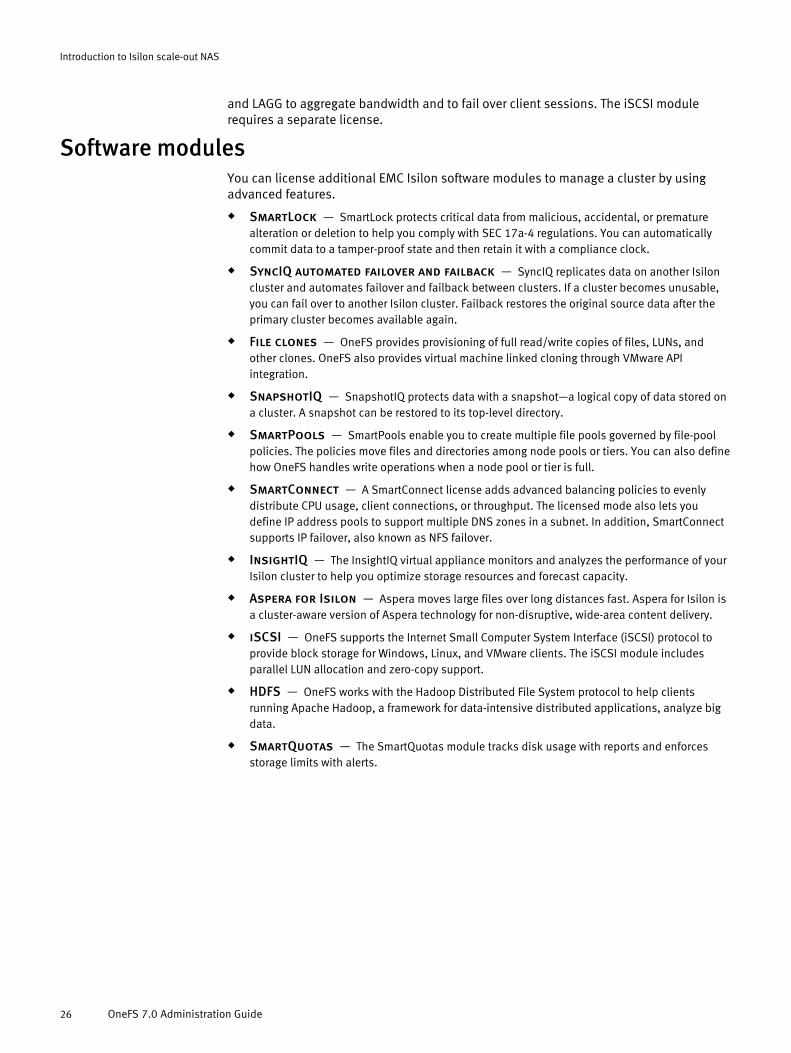
and LAGG to aggregate bandwidth and to fail over client sessions. The iSCSI modulerequires a separate license.
Software modulesYou can license additional EMC Isilon software modules to manage a cluster by usingadvanced features.
u SmartLock — SmartLock protects critical data from malicious, accidental, or prematurealteration or deletion to help you comply with SEC 17a-4 regulations. You can automaticallycommit data to a tamper-proof state and then retain it with a compliance clock.
u SyncIQ automated failover and failback — SyncIQ replicates data on another Isiloncluster and automates failover and failback between clusters. If a cluster becomes unusable,you can fail over to another Isilon cluster. Failback restores the original source data after theprimary cluster becomes available again.
u File clones — OneFS provides provisioning of full read/write copies of files, LUNs, andother clones. OneFS also provides virtual machine linked cloning through VMware APIintegration.
u SnapshotIQ — SnapshotIQ protects data with a snapshot—a logical copy of data stored ona cluster. A snapshot can be restored to its top-level directory.
u SmartPools — SmartPools enable you to create multiple file pools governed by file-poolpolicies. The policies move files and directories among node pools or tiers. You can also definehow OneFS handles write operations when a node pool or tier is full.
u SmartConnect — A SmartConnect license adds advanced balancing policies to evenlydistribute CPU usage, client connections, or throughput. The licensed mode also lets youdefine IP address pools to support multiple DNS zones in a subnet. In addition, SmartConnectsupports IP failover, also known as NFS failover.
u InsightIQ — The InsightIQ virtual appliance monitors and analyzes the performance of yourIsilon cluster to help you optimize storage resources and forecast capacity.
u Aspera for Isilon — Aspera moves large files over long distances fast. Aspera for Isilon isa cluster-aware version of Aspera technology for non-disruptive, wide-area content delivery.
u iSCSI — OneFS supports the Internet Small Computer System Interface (iSCSI) protocol toprovide block storage for Windows, Linux, and VMware clients. The iSCSI module includesparallel LUN allocation and zero-copy support.
u HDFS — OneFS works with the Hadoop Distributed File System protocol to help clientsrunning Apache Hadoop, a framework for data-intensive distributed applications, analyze bigdata.
u SmartQuotas — The SmartQuotas module tracks disk usage with reports and enforcesstorage limits with alerts.
Introduction to Isilon scale-out NAS
26 OneFS 7.0 Administration Guide
CHAPTER 2
Authentication and access control
OneFS supports several methods for ensuring that your cluster remains secure, throughUNIX- and Windows-style data access permissions as well as configuration controlsincluding role-based administration and access zones.
OneFS is designed for a mixed environment in which both Windows Access Control Lists(ACLs) and standard UNIX permissions can be configured on the cluster file system.Windows and UNIX permissions cannot coexist on a single file or directory; however,OneFS uses identity mapping to translate between Windows and UNIX permissions asneeded.
Access zones enable you to partition authentication control configuration based on the IPaddress that a user connects to on the cluster. OneFS includes a built-in access zonenamed "system." By default, new authentication providers, SMB shares, and NFS exportsare added to the system zone. When a new IP address pool is added to the cluster, youcan select a single access zone that will be used when connecting to any IP address inthat pool.
Roles enable you to assign privileges to member users and groups. By default, only the"root" and "admin" users can log in to the web administration interface through HTTP, orthe command-line interface (CLI) through SSH. The root and admin users can then assignother users to built-in or custom roles with login privileges and other privileges that arerequired to perform administrative functions. It is recommended that you assign users toroles that contain the minimum set of privileges necessary.
In most situations, the default permission policy settings, system access zone, and built-in roles are sufficient; however, you can create additional access zones and custom rolesand modify permission policies as necessary for your particular environment.
u Data access control...............................................................................................29u Roles and privileges..............................................................................................31u Authentication......................................................................................................34u Identity management............................................................................................36u Access zones........................................................................................................41u Home directories...................................................................................................42u Managing access permissions...............................................................................45u Managing roles.....................................................................................................52u Create a local user.................................................................................................53u Create a local group..............................................................................................54u Managing users and groups..................................................................................55u Creating file providers...........................................................................................56u Managing file providers.........................................................................................57u Create an Active Directory provider........................................................................59u Managing Active Directory providers......................................................................60u Create an LDAP provider........................................................................................62u Managing LDAP providers......................................................................................65u Create a NIS provider.............................................................................................65u Managing NIS providers........................................................................................66u Create an access zone...........................................................................................67
Authentication and access control 27

u Managing access zones........................................................................................68
Authentication and access control
28 OneFS 7.0 Administration Guide

Data access controlOneFS supports two types of authorization data on a file: Windows-style access controllists (ACLs) and POSIX mode bits (UNIX permissions). The type used is based on the ACLpolicies that are set and on the file-creation method.
Generally, files that are created over SMB or in a directory that has an ACL receive an ACL;otherwise, OneFS relies on the POSIX mode bits that define UNIX permissions. In eithercase, the owner can be represented by a UNIX identifier (UID or GID) or by its Windowsidentifier (SID). The primary group can be represented by a GID or SID. Although modebits are present when a file has an ACL, the mode bits are provided only for protocolcompatibility and are not used for access checks.
During user authorization, OneFS compares the access token that is generated during theinitial connection with the authorization data on the file. All user and identity mappingoccurs during token generation; no mapping takes place when evaluating permissions.
Access to a file or directory can be governed by either a Windows access control list (ACL)or UNIX mode bits. Regardless of the security model, OneFS enforces access rightsconsistently across access protocols. A user is granted or denied the same rights to a filewhen using SMB for Windows file sharing as when using NFS for UNIX file sharing.
The OneFS file system ships with UNIX permissions. By using Windows Explorer or OneFSadministrative tools, you can give a file or directory an ACL. In addition to Windowsdomain users and groups, ACLs in OneFS can include local, NIS, and LDAP users andgroups. After you give a file an ACL, OneFS stops enforcing the file's mode bits, whichremain only as an estimate of the effective permissions.
An EMC Isilon cluster includes global policy settings that enable you to customize thedefault ACL and UNIX permissions to best support your environment. Although you canconfigure ACL policies to optimize a cluster for UNIX or Windows, you should do so only ifyou understand how ACL and UNIX permissions interact.
ACLsIn Windows environments, file and directory permissions, referred to as access rights, aredefined in access control lists (ACLs). Although ACLs are more complex than mode bits,ACLs can express much more granular sets of access rules. OneFS uses the ACLprocessing rules commonly associated with Windows ACLs.
A Windows ACL contains zero or more access control entries (ACEs), each of whichrepresents the security identifier (SID) of a user or a group as a trustee. In OneFS, an ACLcan contain ACEs with a UID, GID, or SID as the trustee. Each ACE contains a set of rightsthat allow or deny access to a file or folder. An ACE can optionally contain an inheritanceflag to specify whether the ACE should be inherited by child folders and files.
Instead of the standard three permissions available for mode bits, ACLs have 32 bits offine-grained access rights. Of these, the upper 16 bits are general and apply to all objecttypes. The lower 16 bits vary between files and directories but are defined in a way thatallows most applications to use the same bits for files and directories.
Rights can be used for granting or denying access for a given trustee. A user's access canbe blocked explicitly through a deny ACE. Access can also be blocked implicitly byensuring that the user does not directly (or indirectly through a group) appear in an ACEthat grants the right in question.
Authentication and access control
Data access control 29
UNIX permissionsIn a UNIX environment, file and directory access is controlled by POSIX mode bits, whichgrant read, write, or execute permissions to the owning user, the owning group, andeveryone else.
OneFS supports the standard UNIX tools for changing permissions, chmod and chown. Formore information, see the OneFS man pages for the chmod, chown, and ls commands.
All files contain 16 permission bits, which provide information about the file or directorytype and the permissions. The lower 9 bits are grouped as three 3-bit sets, called triples,which contain the read ®), write (w), and execute (x) permissions for each class of users(owner, group, and other). You can set permissions flags to grant permissions to each ofthese classes.
Assuming the user is not root, OneFS uses the class to determine whether to grant ordeny access to the file. The classes are not cumulative; the first class matched is used. Itis therefore common to grant permissions in decreasing order.
Mixed-permission environmentsWhen a file operation requests an object’s authorization data (for example, with the ls -l command over NFS or with the Security tab of the Properties dialog box in WindowsExplorer over SMB), OneFS attempts to provide that data in the requested format. In anenvironment that mixes UNIX and Windows systems, some translation may be requiredwhen performing create file, set security, get security, or access operations.
NFS access of Windows-created filesIf a file contains an owning user or group that is a SID, the system attempts to map it to acorresponding UID or GID before returning it to the caller.
In UNIX, authorization data is retrieved by calling stat(2) on a file and examining theowner, group, and mode bits. Over NFSv3, the GETATTR command functions similarly. Thesystem approximates the mode bits and sets them on the file whenever its ACL changes.Mode bit approximations need to be retrieved only to service these calls.
SID-to-UID and SID-to-GID mappings are cached in both the OneFS ID mapper andthe stat cache. If a mapping has recently changed, the file might report inaccurateinformation until the file is updated or the cache is flushed.
SMB access of UNIX-created filesNo UID-to-SID or GID-to-SID mappings are performed when creating an ACL for a file; allUIDs and GIDs are converted to SIDs or principals when the ACL is returned.
OneFS uses a two-step process for returning a security descriptor, which contains SIDs forthe owner and primary group of an object:
1. The current security descriptor is retrieved from the file. If the file does not have adiscretionary access control list (DACL), a synthetic ACL is constructed from the file’slower 9 mode bits, which are separated into three sets of permission triples—oneeach for owner, group, and everyone. For details about mode bits, see "UNIXpermissions."
2. Two access control entries (ACEs) are created for each triple: the allow ACE containsthe corresponding rights that are granted according to the permissions; the deny ACEcontains the corresponding rights that are denied. In both cases, the trustee of the
Authentication and access control
30 OneFS 7.0 Administration Guide

ACE corresponds to the file owner, group, or everyone. After all of the ACEs aregenerated, any that are not needed are removed before the synthetic ACL is returned.
Roles and privilegesIn addition to controlling access to files and directories through ACLs and POSIX modebits, OneFS controls configuration-level access through administrator roles.
A role is a collection of OneFS privileges, usually associated with a configurationsubsystem, that are granted to members of that role as they log in to the cluster throughthe platform API, command-line interface, or web administration interface.
OneFS includes built-in administrator roles with predefined sets of privileges that cannotbe modified. You can also create additional roles with configurable sets of privileges.
Privileges have one of two forms:
u Action — Allows a user to perform a specific action on the cluster. For example theISI_PRIV_LOGIN_SSH privilege allows a user to log in to the cluster through an SSH client.
u Read/Write — Allows a user to view or modify a configuration subsystem such as statistics,snapshots, or quotas. For example, the ISI_PRIV_SNAPSHOT privilege allows an administratorto create and delete snapshots and snapshot schedules. A read/write privilege can grant eitherread-only (RO) or read/write (RW) access. Read-only access allows a user to view configurationsettings; read/write access allows a user to view and modify configuration settings.
OneFS includes a small set of privileges that allow access to Platform API URIs, but do notallow additional configuration through the CLI or web administration interface. Forexample, the ISI_PRIV_EVENT privilege provides access to the /platform/1/event URI,but does not allow access to the isi events CLI command. By default, API-onlyprivileges are part of the built-in SystemAdmin role but are hidden from the systemprivilege list that is viewable by running the isi auth privileges.
Built-in rolesBuilt-in roles include privileges to perform a set of administrative functions.
The following table describes each of the built-in roles from most powerful to leastpowerful. The table includes the privileges and read/write access levels (if applicable)that are assigned to each role. You can assign users and groups to built-in roles as wellas to roles that you create.
Role Description Privileges Read/write access- - - -SecurityAdmin Administer security
configuration on the cluster,including authenticationproviders, local users andgroups, and role membership.
ISI_PRIV_LOGIN_CONSOLE N/A
ISI_PRIV_LOGIN_PAPI N/A
ISI_PRIV_LOGIN_SSH N/A
ISI_PRIV_AUTH Read/write
ISI_PRIV_ROLE Read/write
SystemAdmin Administer all aspects ofcluster configuration that arenot specifically handled by theSecurityAdmin role.
ISI_PRIV_LOGIN_CONSOLE N/A
ISI_PRIV_LOGIN_PAPI N/A
ISI_PRIV_LOGIN_SSH N/A
ISI_PRIV_EVENT Read-only
Authentication and access control
Roles and privileges 31

Role Description Privileges Read/write access- - - -
ISI_PRIV_LICENSE Read-only
ISI_PRIV_NFS Read/write
ISI_PRIV_QUOTA Read/write
ISI_PRIV_SMB Read/write
ISI_PRIV_SNAPSHOT Read/write
ISI_PRIV_STATISTICS Read/write
ISI_PRIV_NS_TRAVERSE N/A
ISI_PRIV_NS_IFS_ACCESS N/A
AuditAdmin View all system configurationsettings.
ISI_PRIV_LOGIN_CONSOLE N/A
ISI_PRIV_LOGIN_PAPI N/A
ISI_PRIV_LOGIN_SSH N/A
ISI_PRIV_LICENSE Read-only
ISI_PRIV_NFS Read-only
ISI_PRIV_QUOTA Read-only
ISI_PRIV_SMB Read-only
ISI_PRIV_SNAPSHOT Read-only
ISI_PRIV_STATISTICS Read-only
OneFS privilegesPrivileges in OneFS are assigned through role membership; they cannot be assigneddirectly to users and groups.
Table 1 Login privileges
OneFS privilege User right Privilege type- - -ISI_PRIV_LOGIN_CONSOLE Log in from the console. Action
ISI_PRIV_LOGIN_PAPI Log in to the Platform APIand the webadministration interface.
Action
ISI_PRIV_LOGIN_SSH Log in using SSH. Action
Authentication and access control
32 OneFS 7.0 Administration Guide
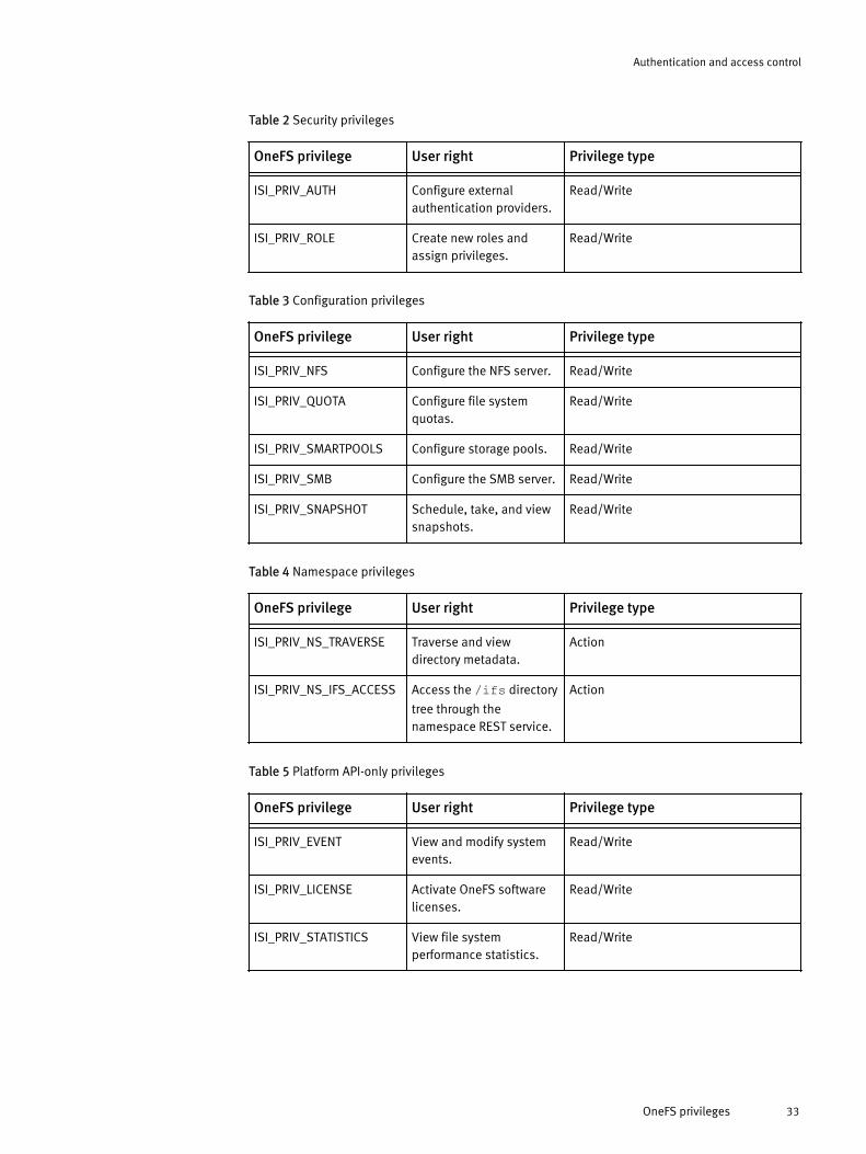
Table 2 Security privileges
OneFS privilege User right Privilege type- - -ISI_PRIV_AUTH Configure external
authentication providers.Read/Write
ISI_PRIV_ROLE Create new roles andassign privileges.
Read/Write
Table 3 Configuration privileges
OneFS privilege User right Privilege type- - -ISI_PRIV_NFS Configure the NFS server. Read/Write
ISI_PRIV_QUOTA Configure file systemquotas.
Read/Write
ISI_PRIV_SMARTPOOLS Configure storage pools. Read/Write
ISI_PRIV_SMB Configure the SMB server. Read/Write
ISI_PRIV_SNAPSHOT Schedule, take, and viewsnapshots.
Read/Write
Table 4 Namespace privileges
OneFS privilege User right Privilege type- - -ISI_PRIV_NS_TRAVERSE Traverse and view
directory metadata.Action
ISI_PRIV_NS_IFS_ACCESS Access the /ifs directory
tree through thenamespace REST service.
Action
Table 5 Platform API-only privileges
OneFS privilege User right Privilege type- - -ISI_PRIV_EVENT View and modify system
events.Read/Write
ISI_PRIV_LICENSE Activate OneFS softwarelicenses.
Read/Write
ISI_PRIV_STATISTICS View file systemperformance statistics.
Read/Write
Authentication and access control
OneFS privileges 33

AuthenticationOneFS supports a variety of local and remote authentication providers to verify that usersattempting to access the cluster are who they claim to be. Anonymous access, whichdoes not require authentication, is supported for protocols that allow it.
To use an authentication provider, it must be added to an access zone. By default, whenyou create an authentication provider it is added to the built-in system zone, whichalready includes a local provider and a file provider. You can create multiple instances ofeach provider type, but it is recommended that you only use a single instance of aprovider type within an access zone. For more information about creating and managingaccess zones, see "Access zones."
OneFS supports the concurrent use of multiple authentication providers. For example,OneFS is frequently configured to authenticate Windows clients with Active Directory andto authenticate UNIX clients with LDAP. It is important that you understand theirinteractions before enabling multiple providers on the cluster.
Authentication providers support a mix of the following features:
u Authentication. All authentication providers support plain text authentication; someproviders can also be configured to support NTLM or Kerberos authentication.
u Ability to manage users and groups directly on the cluster.
u Netgroups. Used primarily by NFS, netgroups configure access to NFS exports.
u UNIX-centric user and group properties such as login shell, home directory, UID, andGID. Missing information is supplemented by configuration templates or additionalauthentication providers.
u Windows-centric user and group properties such as NetBIOS domain and SID.Missing information is supplemented by configuration templates.
Local providerThe local provider provides authentication and lookup facilities for user accounts thatwere added by an administrator. Local users do not include system accounts such as rootor admin. The local provider also maintains local group membership. Localauthentication can be useful when Active Directory, LDAP, or NIS directory services arenot used, or when a specific user or application needs to access the cluster.
Unlike UNIX groups, local groups can include built-in groups and Active Directory groupsas members. Local groups can also include users from other providers. Netgroups are notsupported in the local provider.
Each access zone in the cluster contains a separate instance of the local provider, whichallows each access zone to have its own list of local users that can authenticate to it.
File providerA file provider enables you to supply an authoritative third-party source of user and groupinformation to the cluster. A third-party source is useful in UNIX environments wherepasswd, group, and netgroup files are synchronized across multiple UNIX servers.
OneFS uses standard BSD /etc/spwd.db and /etc/group database files as the backingstore for the file provider. You generate the spwd.db file by running the pwd_mkdbcommand-line utility. You can script updates to the database files.
Authentication and access control
34 OneFS 7.0 Administration Guide

The built-in system file provider includes services to list, manage, andauthenticate against system accounts such as root, admin, and nobody. Modifying thesystem file provider is not recommended.
Active DirectoryThe Active Directory directory service is a Microsoft implementation of LightweightDirectory Access Protocol (LDAP), Kerberos, and DNS technologies that can storeinformation about network resources. Active Directory can serve many functions, but theprimary reason for joining the cluster to an Active Directory domain is to perform user andgroup authentication.
When the cluster joins an Active Directory domain, a single Active Directory machineaccount is created. The machine account is used to establish a trust relationship with thedomain and to enable the cluster to authenticate and authorize users in the ActiveDirectory forest. By default, the machine account is named the same as the cluster;however, if the cluster name is more than 15 characters long, the name is hashed anddisplayed after joining the domain.
Whenever possible, a single Active Directory instance should be used when all domainshave a trust relationship. Multiple instances should be used only to grant access tomultiple sets of mutually-untrusted domains.
LDAPThe Lightweight Directory Access Protocol (LDAP) is a networking protocol that enablesyou to define, query, and modify directory services and resources.
OneFS can authenticate users and groups against an LDAP repository in order to grantthem access to the cluster.
The LDAP service supports the following features:
u Users, groups, and netgroups.
u Configurable LDAP schemas. For example, the ldapsam schema allows NTLMauthentication over the SMB protocol for users with Windows-like attributes.
u Simple bind authentication (with and without SSL).
u Redundancy and load balancing across servers with identical directory data.
u Multiple LDAP provider instances for accessing servers with different user data.
u Encrypted passwords.
NISThe Network Information Service (NIS) provides authentication and identity uniformityacross local area networks. OneFS includes a NIS authentication provider that enablesyou to integrate the cluster with your NIS infrastructure.
NIS, designed by Sun Microsystems, can be used to authenticate users and groups whenthey access the cluster. The NIS provider exposes the passwd, group, and netgroup mapsfrom a NIS server. Hostname lookups are also supported. Multiple servers can bespecified for redundancy and load balancing.
NIS is different from NIS+, which OneFS does not support.
Authentication and access control
Active Directory 35
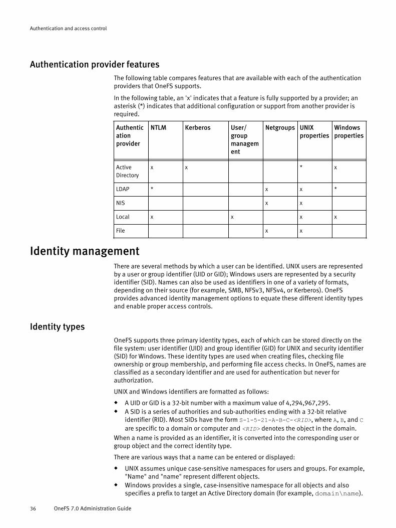
Authentication provider featuresThe following table compares features that are available with each of the authenticationproviders that OneFS supports.
In the following table, an 'x' indicates that a feature is fully supported by a provider; anasterisk (*) indicates that additional configuration or support from another provider isrequired.
Authenticationprovider
NTLM Kerberos User/groupmanagement
Netgroups UNIXproperties
Windowsproperties
- - - - - - -ActiveDirectory
x x * x
LDAP * x x *
NIS x x
Local x x x x
File x x
Identity managementThere are several methods by which a user can be identified. UNIX users are representedby a user or group identifier (UID or GID); Windows users are represented by a securityidentifier (SID). Names can also be used as identifiers in one of a variety of formats,depending on their source (for example, SMB, NFSv3, NFSv4, or Kerberos). OneFSprovides advanced identity management options to equate these different identity typesand enable proper access controls.
Identity typesOneFS supports three primary identity types, each of which can be stored directly on thefile system: user identifier (UID) and group identifier (GID) for UNIX and security identifier(SID) for Windows. These identity types are used when creating files, checking fileownership or group membership, and performing file access checks. In OneFS, names areclassified as a secondary identifier and are used for authentication but never forauthorization.
UNIX and Windows identifiers are formatted as follows:
u A UID or GID is a 32-bit number with a maximum value of 4,294,967,295.u A SID is a series of authorities and sub-authorities ending with a 32-bit relative
identifier (RID). Most SIDs have the form S-1-5-21-A-B-C-<RID>, where A, B, and Care specific to a domain or computer and <RID> denotes the object in the domain.
When a name is provided as an identifier, it is converted into the corresponding user orgroup object and the correct identity type.
There are various ways that a name can be entered or displayed:
u UNIX assumes unique case-sensitive namespaces for users and groups. For example,"Name" and "name" represent different objects.
u Windows provides a single, case-insensitive namespace for all objects and alsospecifies a prefix to target an Active Directory domain (for example, domain\name).
Authentication and access control
36 OneFS 7.0 Administration Guide
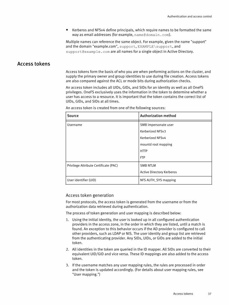
u Kerberos and NFSv4 define principals, which require names to be formatted the sameway as email addresses (for example, [email protected]).
Multiple names can reference the same object. For example, given the name "support"and the domain "example.com", support, EXAMPLE\support, [email protected] are all names for a single object in Active Directory.
Access tokensAccess tokens form the basis of who you are when performing actions on the cluster, andsupply the primary owner and group identities to use during file creation. Access tokensare also compared against the ACL or mode bits during authorization checks.
An access token includes all UIDs, GIDs, and SIDs for an identity as well as all OneFSprivileges. OneFS exclusively uses the information in the token to determine whether auser has access to a resource. It is important that the token contains the correct list ofUIDs, GIDs, and SIDs at all times.
An access token is created from one of the following sources:
Source Authorization method- -Username SMB impersonate user
Kerberized NFSv3
Kerberized NFSv4
mountd root mapping
HTTP
FTP
Privilege Attribute Certificate (PAC) SMB NTLM
Active Directory Kerberos
User identifier (UID) NFS AUTH_SYS mapping
Access token generationFor most protocols, the access token is generated from the username or from theauthorization data retrieved during authentication.
The process of token generation and user mapping is described below:
1. Using the initial identity, the user is looked up in all configured authenticationproviders in the access zone, in the order in which they are listed, until a match isfound. An exception to this behavior occurs if the AD provider is configured to callother providers, such as LDAP or NIS. The user identity and group list are retrievedfrom the authenticating provider. Any SIDs, UIDs, or GIDs are added to the initialtoken.
2. All identities in the token are queried in the ID mapper. All SIDs are converted to theirequivalent UID/GID and vice versa. These ID mappings are also added to the accesstoken.
3. If the username matches any user mapping rules, the rules are processed in orderand the token is updated accordingly. (For details about user mapping rules, see"User mapping.")
Authentication and access control
Access tokens 37

The default on-disk identity is calculated using the final token and the global setting.These identities are used for newly created files.
ID mappingThe file access protocols provided by OneFS support a limited number of identity types:UIDs, GIDs, and SIDs. When an identity is requested that does not match the stored type,a mapping is required. Administrators with advanced knowledge of UNIX and Windowsidentities can modify the default settings that determine how those identities aremapped in the system.
Mappings are stored in a cluster-distributed database called the ID mapper. Whenretrieving a mapping from the database, as input the ID mapper takes a source and targetidentity type (UID, GID, or SID). If a mapping already exists between the specified sourceand the requested type, that mapping is returned; otherwise, a new mapping is created.
Each mapping is stored as a one-way relationship from source to destination. Two-waymappings are presented as two complementary one-way mappings in the database.
There are four types of identity mappings. The mapping type and identity sourcedetermine whether these mappings are stored persistently in the ID mapper.
u External mappings are derived from identity sources outside OneFS. For example,Active Directory (AD) can store a UID or GID along with a SID. When retrieving the SIDfrom AD, the UID/GID is also retrieved and used for mappings on OneFS. By default,mappings derived from AD are not persistently stored in the ID mapper, but mappingsfrom other external identity sources including LDAP and NIS are persistently stored.
u Algorithmic mappings are created by adding a UID or GID to a well-known base SID,resulting in a temporary “UNIX SID.” (For more information, see “Mapping UNIX IDs toWindows IDs.”) Unlike external mappings, algorithmic mappings are not persistentlystored in the ID mapper database.
u Manual mappings are set explicitly by running the isi auth mapping command atthe command line. For command syntax and examples, see the OneFS CommandReference. Manual mappings are stored persistently in the ID mapper database.
u Automatic mappings are generated if no other mapping type can be found. A SID ismapped to a UID or GID out of the default range of 1,000,000-2,000,000. This rangeis assumed to be otherwise unused, and a check is made only to ensure there is nomapping from the given UID before it is used. After creation, these mappings arestored persistently in the ID mapper database.
Mapping Windows IDs to UNIX IDsIf the caller requests a SID-to-UID or SID-to-GID mapping, the actual object (an AD user orgroup) must first be located.
After the object is located, the following rules are applied to create two mappings, one ineach direction:
1. If the object has an associated UID or GID (an external mapping), create a mappingfrom the SID.
2. If a mapping for the SID already exists in the ID mapper database, use that mapping.
3. Determine whether a lookup of the user or group is necessary in an external source,according to the following conditions:l The user or group is in the primary domain or one of the listed lookup domains.
l Lookup is enabled for users or groups.
4. If a lookup is necessary, follow these steps:a. By default, normalize the user or group name to lowercase.
Authentication and access control
38 OneFS 7.0 Administration Guide

b. Search all authentication providers except Active Directory for a matching user orgroup object by name.
c. If an object is found, use the associated UID or GID to create an external mapping.
5. Allocate an automatic mapping from the configured range.
Mapping UNIX IDs to Windows IDsUID-to-SID and GID-to-SID mappings are used only if the caller requests a mapping to becreated and one did not already exist. Resulting “UNIX SIDs” are never stored on-disk.
UIDs and GIDs have a set of pre-defined mappings to and from SIDs.
If a UID-to-SID or GID-to-SID mapping is requested, a temporary UNIX SID is generated inthe format S-1-22-1-<UID> or S-1-22-2-<GID> by using the following rules:
u UIDs are mapped to a SID with a domain of S-1-22-1 and a resource ID (RID)matching the UID. For example, the UNIX SID for UID 600 is S-1-22-1-600.
u GIDs are mapped to a SID with a domain of S-1-22-2 and a RID matching the GID. Forexample, the UNIX SID for GID 800 is S-1-22-2-800.
On-disk identity selectionOnesFS can store either UNIX or Windows identities in file metadata on disk. Theidentities are set when a file is created or a file's access control data is modified.Choosing the preferred identity to store is important because nearly all protocols requiresome level of mapping to operate correctly. You can choose to store the UNIX or theWindows identity, or allow OneFS to determine the optimal identity to store.
u The on-disk selection does not guarantee the preferred identity can always be storedon disk.
u On new installations, the on-disk identity is set to native, which is optimized for amixed Windows and UNIX environment.
u When you upgrade from OneFS 6.0 or earlier, the on-disk identity is set to unix tomatch the file system behavior of those earlier versions without requiring an upgradeof all your files and directories.
The available on-disk identities and the corresponding actions taken by the systemauthentication daemon are described below.
u native: Determine the identity to store on disk by checking the following ID mappingtypes in order. The first rule that applies is used to set the on-disk identity.1. Algorithmic mappings: If an incoming SID matches S-1-22-1-<UID> or
S-1-22-2-<GID> (also called a "UNIX SID"), convert it back to the correspondingUID or GID and set it as the on-disk identity.
2. External mappings: If an incoming UID or GID is defined in an external provider(AD, LDAP, or NIS), set it as the on-disk identity.
3. Persistent mappings (usually created with the isi auth mapping createcommand): If an incoming identity has a mapping that is stored persistently in theID mapper database, store the incoming identity as the on-disk identity unless themapping is flagged as on-disk (in which case, set the target ID as the on-diskidentity). For example, if a mapping of GID:10000 -> S-1-5-32-545 exists andthe --on-disk option has been set with the isi auth mapping modifycommand, a request for the on-disk storage of GID:10000 returnsS-1-5-32-545.
Authentication and access control
On-disk identity selection 39

4. Automatic mappings: If an incoming SID is not mapped to a UID or GID, set the SIDas the on-disk identity. If a UNIX identifier is later required (for example, for cross-protocol NFS or local file system access), a mapping to an auto-allocated UNIXidentifier is created.
u unix: Always store incoming UNIX identifiers on disk. For incoming SIDs, search theconfigured authentication providers by user name. If a match is found, the SID ismapped to either a UID or GID. If the SID does not exist on the cluster (for example, itis local to the client or part of an untrusted AD domain), a UID or GID is allocated fromthe ID mapper database and stored on disk, and the resulting SID-to-UID or -GIDmapping is stored in the ID mapper database.
u sid: Store incoming SIDs on disk, with the exception of temporary UNIX SIDs, whichare always converted back to their corresponding UNIX identifiers before being storedon disk. For incoming UIDs or GIDs, search the configured authentication providers. Ifa match is found, store the SID on disk; otherwise, store the UNIX identity.
User mapping across identitiesUser mapping provides a way to control the permissions given to users by specifyingwhich user and group identifiers (SIDs, UIDs, and GIDs) the user has. These identifiers areused when creating files and when checking file or group ownership. Mapping rules canbe used to rename users, add supplemental user identities, and modify a user's groupmembership. User mapping is performed only during login or protocol access.
Configuring user mappingYou can create and configure user mapping rules in each access zone.
By default, every mapping rule is processed. This behavior allows multiple rules to beapplied, but can present problems when applying a “deny all" rule such as "deny allunknown users." Additionally, replacement rules may interact with rules that containwildcard characters.
To minimize complexity when configuring multiple mapping rules, it is recommended thatyou group rules by type and organize them in the following order:
1. Replacements: Any user renaming should be processed first to ensure that allinstances of the name are replaced.
2. Joins: After the names are set by any replacement operations, use join, add, andinsert rules to add extra identifiers.
3. Allow/deny: All processing must be stopped before a default deny rule can beapplied. To do this, create a rule that matches allowed users but does nothing (suchas an add operator with no field options) and has the break option. After enumeratingthe allowed users, a catchall deny may be placed at the end to replace anybodyunmatched with an empty user.
Within each group of rules, put explicit rules before rules involving wildcard characters;otherwise, the explicit rules might be skipped.
Authentication and access control
40 OneFS 7.0 Administration Guide

Well-known security identifiersThe OneFS file system can store any SID it receives in a file's ACL, including all well-known SIDs; however, only a small subset of well-known SIDs have meaning in OneFS.
Table 6 Well-known SIDs
SID Name Description- - -S-1-1-0 Everyone A system-controlled list of all users,
including anonymous users andguests. If set on an ACL, this SIDgrants file or directory access to allusers. If assigned to a role, all usersare considered members of that role.
S-1-3-0 Creator Owner A placeholder in an inheritable accesscontrol entry (ACE) for the identity ofthe object's creator. This well-knownSID is replaced when the ACE isinherited.
S-1-3-1 Creator Group A placeholder in an inheritable ACE forthe identity of the object creator'sprimary group. This well-known SID isreplaced when the ACE is inherited.
S-1-3-4 Owner Rights A group that represents the object'scurrent owner which, when applied toan object through an ACE, instructsthe system to ignore the objectowner's implied READ_CONTROL andWRITE_DAC permissions.
S-1-5-21-domain-501 Guest An account for users who do not haveindividual accounts. This accountdoes not require a password andcannot log in to a shell. By default, theGuest account is mapped to the UNIX'nobody' account and is disabled.
S-1-5-32-544 Administrators A built-in group whose members canadminister the cluster throughMicrosoft MMC RPC calls. After theinitial OneFS installation, this groupcontains only the Administratoraccount. The Domain Admins group isadded to this group the first time acluster is joined to an Active Directorydomain.
Access zonesAccess zones provide a way to partition cluster configuration into self-contained units,allowing a subset of parameters to be configured as a virtual cluster. OneFS includes a
Authentication and access control
Well-known security identifiers 41

built-in access zone called "system." By default, all cluster IP addresses connect to thesystem zone, which contains all configured authentication providers, all available SMBshares, and all available NFS exports.
Access zones contain all of the necessary configuration settings to supportauthentication and identity management services in OneFS.
You can create additional access zones and configure each zone with its own set ofauthentication providers, user mapping rules, and SMB shares. NFS users can only beauthenticated against the system zone. Multiple access zones are particularly useful forserver consolidation, for example when merging multiple Windows file servers that arepotentially joined to different untrusted forests.
If you create access zones, it is recommended that you use them for data access only andthat you use the system zone strictly for configuration access. To use an access zone, youmust configure your network settings to map an IP address pool to the zone.
Home directoriesWhen you create a local user, OneFS automatically creates a home directory for the user.OneFS also supports dynamic home directory creation for users who access the cluster byconnecting to an SMB share or by logging in through FTP or SSH. Regardless of themethod by which a home directory was created, you can configure access to the homedirectory through a combination of SMB, SSH, and FTP.
Home directory creation through SMBYou can create a special SMB share that includes expansion variables in the share path,enabling users to access their home directories by connecting to the share. You canenable dynamic creation of home directories that do not exist at SMB connection time.
By default, an SMB share's directory path is created with a synthetic ACL based on modebits. You can enable the "inheritable ACL" setting on a share to specify that, if the parentdirectory has an inheritable ACL, it will be inherited on the share path.
For details about creating and modifying SMB shares through the CLI, see the isi smbcreate and isi smb modify entries in the OneFS Command Reference.
Home directory creation through SSH and FTPFor users who access the cluster through SSH or FTP, you can configure home directorysupport by modifying authentication provider settings.
The following authentication provider settings determine how home directories are setup.
u Home Directory Naming — Specifies the path to use as a template for naming homedirectories. The path must begin with /ifs and may contain variables, such as %U, that are
expanded to generate the home directory path for the user.
u Create home directories on first login — Specifies whether to create a homedirectory the first time a user logs in, if a home directory does not already exist for the user.
u UNIX Shell — Specifies the path to the user's login shell. This setting applies only to userswho access the file system through SSH.
Authentication and access control
42 OneFS 7.0 Administration Guide

Home directory creation in mixed environmentsIf a user will log in through both SMB and SSH, it is recommended that you set up thehome directory such that the path template is the same in both the SMB share and theauthentication provider against which the user is authenticating through SSH.
Home directory permissionsA user's home directory can be set up with a Windows ACL or with POSIX mode bits,which are then converted into a synthetic ACL. The method by which a home directory iscreated determines the initial permissions that are set on the home directory.
When you create a local user, the user's home directory is created with mode bits bydefault.
For users who authenticate against external sources, home directories can bedynamically created at login time. If a home directory is created during a login throughSSH or FTP, it is set up with mode bits; if a home directory is created during an SMBconnection, it receives either mode bits or an ACL. For example, if an LDAP user first logsin through SSH or FTP, the user's home directory is created with mode bits. However, ifthe same user first connects through an SMB share, the home directory is created withthe permissions indicated by the configured SMB settings. If the "inherited path ACL"setting is enabled, an ACL is generated; otherwise, mode bits are used.
Because SMB sends an NT password hash to authenticate SMB users, only usersfrom authentication providers that can handle NT hashes can log in over SMB. Theseproviders include the local provider, Active Directory, and LDAP with Samba extensionsenabled. File, NIS, and non-Samba LDAP users cannot log in over SMB.
Dot file provisioningHome directories that are created through SSH or FTP are provisioned with configurationfiles that are pulled from a template "skeleton" directory. The skeleton directory isdefined in the configuration settings of the user's access zone.
The skeleton directory, which is located at /usr/share/skel by default, contains a setof files that are copied to the user's home directory when a local user is created or when auser home directory is dynamically created during login. Files in the skeleton directorythat begin with dot. are renamed to remove the dot prefix when they are copied to theuser's home directory. For example, dot.cshrc is copied to the user's home directoryas .cshrc. This format enables dot files in the skeleton directory to be viewable throughthe command-line interface without requiring the ls -a command.
For SMB shares that might use home directories that were provisioned with dot files, youcan set an option to prevent users who connect to the share through SMB from viewingthe dot files.
For example, the following command modifies an SMB share named "homedir" to hidedot files:
isi smb modify share homedir --hide-dot-files=yes
For a user who can access the cluster both through SMB and through an SSH orFTP login, dot files are not provisioned if the user's home directory is created dynamicallythrough an SMB connection; however, they can be manually copied from the skeletondirectory of the user's access zone. You can find the location of the skeleton directory byrunning the isi zone zones view command through the OneFS command-line interface.
Authentication and access control
Home directory creation in mixed environments 43

Default home directory settings in authentication providersThe default settings that affect how home directories are set up differ based on theauthentication provider that the user authenticates against.
Authenticationprovider
Home directorynaming
Home directorycreation
UNIX login shell
- - - -Local /ifs/home/%U Enabled /bin/sh
File None Disabled None
Active Directory /ifs/home/%D/%U
If available,provider informationoverrides this value.
Disabled /bin/sh
LDAP None Disabled None
NIS None Disabled None
Supported expansion variablesYou can include expansion variables in an SMB share path or in an authenticationprovider's home directory template.
OneFS supports the following expansion variables.
Variable Description- -%U Expands to the user name, for example,
user_001. This variable is typically included atthe end of the path, for example, /ifs/home/%U.
%D Expands to the user's domain name, whichvaries by authentication provider:
l For Active Directory users, %D expands tothe Active Directory NetBIOS name.
l For local users, %D expands to the clustername in uppercase characters. Forexample, given a cluster namedcluster1, %D expands to CLUSTER1.
l For users in the system file provider, %Dexpands to UNIX_USERS.
l For users in a file provider other than thesystem provider, %D expands toFILE_USERS.
l For LDAP users, %D expands toLDAP_USERS.
l For NIS users, %D expands to NIS_USERS.
Authentication and access control
44 OneFS 7.0 Administration Guide

Variable Description- -%Z Expands to the access zone name, for example,
System. If multiple zones are activated, this
variable is useful for differentiating users inseparate zones. For example, given the path /ifs/home/%Z/%U, a user named "admin7" in
the system zone will be mapped to /ifs/home/System/admin7.
%L Expands to the host name of the cluster,normalized to lowercase.
%0 Expands to the first character of the user name.
%1 Expands to the second character of the username.
%2 Expands to the third character of the username.
If the user name includes fewer than three characters the %0, %1, and %2variables wrap around. For example, given a user named "ab" the %2 variable maps to a;given a user named "a", all three variables map to a.
Managing access permissionsThe internal representation of identities and permissions can contain information fromUNIX sources, Windows sources, or both. Because access protocols can process theinformation from only one of these sources, the system may need to makeapproximations to present the information in a format the protocol can process.
Configure access management settingsYou can configure default access settings, including the identity type to store on-disk; theWindows workgroup name to use when running in local mode and whether to sendNTLMv2 responses for SMB connections; and character substitution for spacesencountered in user and group names.
If you change the on-disk identity, it is recommended that you also run the RepairPermissions job.
1. Click Cluster Management > Access Management > Settings.
2. Configure the following settings as needed.l Send NTLMv2: Configures the type of NTLM response that is sent to an SMB client.
Acceptable values are: yes, no (default).
l On-Disk Identity: Controls the preferred identity to store on-disk. If OneFS is unableto convert an identity to the preferred format, it is stored as-is. This setting doesnot affect identities that are currently stored on-disk. Select one of the followingsettings:– native: Let OneFS determine the identity to store on-disk. This is the
recommended setting.
– unix: Always store incoming UNIX identifiers (UIDs and GIDs) on-disk.
Authentication and access control
Managing access permissions 45

– sid: Store incoming Windows security identifiers (SIDs) on-disk, unless the SIDwas generated from a UNIX identifier; in that case, convert it back to the UNIXidentifier and store it on-disk.
If you change the on-disk identity selection, permission errors may occur unlessyou run the Repair Permissions job as described in the final step of thisprocedure.
l Workgroup: Specifies the NetBIOS workgroup. The default value is WORKGROUP.
l Space Replacement: For clients that have difficulty parsing spaces in user and groupnames, specifies a substitute character.
3. Click Save.
4. If you changed the on-disk identity, run the Repair Permissions 'Convert Permissions'task to prevent potential permission errors.a. Click Protocols > ACLs > Repair Permissions Job.
b. Optional: Modify the Priority and Impact policy settings.
c. For the Repair task setting, click to select Convert permissions.
d. For the Path to repair setting, type or click Browse to select the path to the directorywhose permissions you want to repair.
e. For the Target setting, ensure the Use default system type option is selected.
f. For the Access Zone setting, click to select the zone that is using the directoryspecified in the Path to repair setting.
g. Click Start.
Modify ACL policy settingsThe default ACL policy settings are sufficient for most cluster deployments. Because theychange the behavior of permissions throughout the system, these policies should bemodified only as necessary by experienced administrators with advanced knowledge ofWindows ACLs. This is especially true for the advanced settings, which are appliedregardless of the cluster's environment.
For UNIX, Windows, or balanced environments, the optimal permission policy settings areselected and cannot be modified. However, you can choose to manually configure thecluster's default permission settings if necessary to support your particular environment.
1. Click Protocols > ACLs > ACL Policies.
2. In the Standard Settings section, under Environment, click to select the setting that bestdescribes your environment, or select Configure permission policies manually toconfigure individual permission policies.
UNIX only Causes cluster permissions to operate with UNIX semantics, asopposed to Windows semantics. Enabling this option preventsACL creation on the system.
Balanced Causes cluster permissions to operate in a mixed UNIX andWindows environment. This setting is recommended for mostcluster deployments.
Authentication and access control
46 OneFS 7.0 Administration Guide
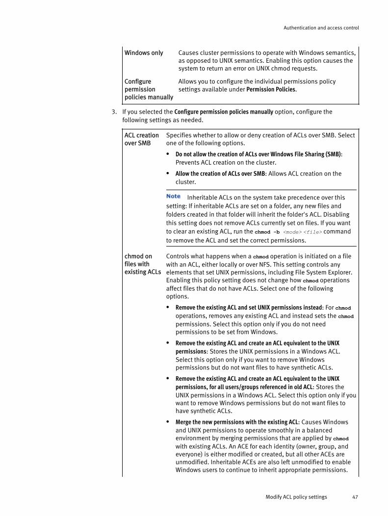
Windows only Causes cluster permissions to operate with Windows semantics,as opposed to UNIX semantics. Enabling this option causes thesystem to return an error on UNIX chmod requests.
Configurepermissionpolicies manually
Allows you to configure the individual permissions policysettings available under Permission Policies.
3. If you selected the Configure permission policies manually option, configure thefollowing settings as needed.
ACL creationover SMB
Specifies whether to allow or deny creation of ACLs over SMB. Selectone of the following options.
l Do not allow the creation of ACLs over Windows File Sharing (SMB):Prevents ACL creation on the cluster.
l Allow the creation of ACLs over SMB: Allows ACL creation on thecluster.
Inheritable ACLs on the system take precedence over thissetting: If inheritable ACLs are set on a folder, any new files andfolders created in that folder will inherit the folder's ACL. Disablingthis setting does not remove ACLs currently set on files. If you wantto clear an existing ACL, run the chmod -b <mode> <file> commandto remove the ACL and set the correct permissions.
chmod onfiles withexisting ACLs
Controls what happens when a chmod operation is initiated on a filewith an ACL, either locally or over NFS. This setting controls anyelements that set UNIX permissions, including File System Explorer.Enabling this policy setting does not change how chmod operationsaffect files that do not have ACLs. Select one of the followingoptions.
l Remove the existing ACL and set UNIX permissions instead: For chmodoperations, removes any existing ACL and instead sets the chmodpermissions. Select this option only if you do not needpermissions to be set from Windows.
l Remove the existing ACL and create an ACL equivalent to the UNIXpermissions: Stores the UNIX permissions in a Windows ACL.Select this option only if you want to remove Windowspermissions but do not want files to have synthetic ACLs.
l Remove the existing ACL and create an ACL equivalent to the UNIXpermissions, for all users/groups referenced in old ACL: Stores theUNIX permissions in a Windows ACL. Select this option only if youwant to remove Windows permissions but do not want files tohave synthetic ACLs.
l Merge the new permissions with the existing ACL: Causes Windowsand UNIX permissions to operate smoothly in a balancedenvironment by merging permissions that are applied by chmodwith existing ACLs. An ACE for each identity (owner, group, andeveryone) is either modified or created, but all other ACEs areunmodified. Inheritable ACEs are also left unmodified to enableWindows users to continue to inherit appropriate permissions.
Authentication and access control
Modify ACL policy settings 47

However, UNIX users can set specific permissions for each ofthose three standard identities.
l Deny permission to modify the ACL: Prevents users from making NFSand local chmod operations. Enable this setting if you do not wantto allow permission sets over NFS.
If you try to run the chmod command on the same permissions thatare currently set on a file with an ACL, you may cause the operationto silently fail—The operation appears to be successful, but if youwere to examine the permissions on the cluster, you would noticethat the chmod command had no effect. As a workaround, you canrun the chmod command away from the current permissions and thenperform a second chmod command to revert to the originalpermissions. For example, if your file shows 755 UNIX permissionsand you want to confirm this number, you could run chmod 700file; chmod 755 file
ACLs createdondirectories byUNIX chmod
On Windows systems, the access control entries for directories candefine fine-grained rules for inheritance; on UNIX, the mode bits arenot inherited. Making ACLs that are created on directories by thechmod command inheritable is more secure for tightly controlledenvironments but may deny access to some Windows users whowould otherwise expect access.
Select one of the following options.
l Make them inheritable
l Do not make them inheritable
chown on fileswith existingACLs
Changes a file or folder's owning user or group. Select one of thefollowing options.
l Modify the owner and/or group permissions: Causes the chownoperation to perform as it does in UNIX. Enabling this settingmodifies any ACEs in the ACL associated with the old and newowner or group.
l Do not modify the ACL: Cause the NFS chown operation to functionas it does in Windows. When a file owner is changed overWindows, no permissions in the ACL are changed.
Over NFS, the chown operation changes the permissions andthe owner or owning group. For example, consider a file owned byuser Joe with "rwx------" (700) permissions, signifying "rwx"permissions for the owner, but no permissions for anyone else. If yourun the chown command to change ownership of the file to user Bob,the owner permissions are still "rwx" but they now represent thepermissions for Bob, rather than for Joe. In fact, Joe will have lost allof his permissions. This setting does not affect UNIX chownoperations performed on files with UNIX permissions, and it does notaffect Windows chown operations, which do not change anypermissions.
Authentication and access control
48 OneFS 7.0 Administration Guide

Accesschecks(chmod,chown)
In UNIX environments, only the file owner or superuser has the rightto run a chmod or chown operation on a file. In Windowsenvironments, you can implement this policy setting to give usersthe right to perform chmod operations, called the "changepermissions" right, or the right to perform chown operations, calledthe "take ownership" right.
The "take ownership" right only gives users the ability to takefile ownership, not to give ownership away.
Select one of the following options.
l Allow only owners to chmod or chown: Causes chmod and chownaccess checks to operate with UNIX-like behavior.
l Allow owner and users with 'take ownership' right to chown, and ownerand users with 'change permissions' right to chmod: Causes chmodand chown access checks to operate with Windows-like behavior.
4. In the Advanced Settings section, configure the following settings as needed.
Treatment of"rwx"permissions
In UNIX environments, "rwx" permissions signify two things: A useror group has read, write, and execute permissions; and a user orgroup has the maximum possible level of permissions.
When you assign UNIX permissions to a file, no ACLs are stored forthat file. However, a Windows system processes only ACLs;Windows does not process UNIX permissions. Therefore, when youview a file's permissions on a Windows system, the cluster musttranslate the UNIX permissions into an ACL. This type of ACL iscalled a synthetic ACL. Synthetic ACLs are not stored anywhere;instead, they are dynamically generated as needed and then theyare discarded. If a file has UNIX permissions, you may noticesynthetic ACLs when you run the ls file command on the cluster inorder to view a file’s ACLs.
When you generate a synthetic ACL, the cluster maps UNIXpermissions to Windows rights. Windows supports a more granularpermissions model than UNIX does, and it specifies rights thatcannot easily be mapped from UNIX permissions. If the cluster maps"rwx" permissions to Windows rights, you must enable one of thefollowing options. The main difference between "rwx" and "FullControl" is the broader set of permissions with "Full Control".
Select one of the following options.
l Retain 'rwx' permissions: Generates an ACE that provides onlyread, write, and execute permissions.
l Treat 'rwx' permissions as Full Control: Generates an ACE thatprovides the maximum Windows permissions for a user or agroup by adding the "change permissions" right, the "takeownership" right, and the "delete" right.
Group ownerinheritance
Operating systems tend to work with group ownership andpermissions in two different ways: BSD inherits the group ownerfrom the file's parent folder; Windows and Linux inherit the groupowner from the file creator's primary group. If you enable a setting
Authentication and access control
Modify ACL policy settings 49

that causes the group owner to be inherited from the creator'sprimary group, it can be overridden on a per-folder basis by runningthe chmod command to set the set-gid bit. This inheritance appliesonly when the file is created. For more information, see the manualpage for the chmod command.
Select one of the following options.
l When an ACL exists, use Linux and Windows semantics, otherwise useBSD semantics: Controls file behavior based on whether the newfile inherits ACLs from its parent folder. If it does, the file usesthe creator's primary group. If it does not, the file inherits fromits parent folder.
l BSD semantics - Inherit group owner from the parent folder: Causesthe group owner to be inherited from the file's parent folder.
l Linux and Windows semantics - Inherit group owner from the creator'sprimary group: Causes the group owner to be inherited from thefile creator's primary group.
chmod (007)on files withexisting ACLs
Specifies whether to remove ACLs when running the chmod (007)command. Select one of the following options.
l chmod(007) does not remove existing ACL: Sets 007 UNIXpermissions without removing an existing ACL.
l chmod(007) removes existing ACL and sets 007 UNIX permissions:Removes ACLs from files over UNIX file sharing (NFS) and locallyon the cluster through the chmod (007) command. If you enablethis setting, be sure to run the chmod command on the fileimmediately after using chmod (007) to clear an ACL. In mostcases, you do not want to leave 007 permissions on the file.
Ownerpermissions
It is impossible to represent the breadth of a Windows ACL's accessrules using a set of UNIX permissions. Therefore, when a UNIX clientrequests UNIX permissions for a file with an ACL over NFS (an actionknown as a "stat"), it receives an imperfect approximation of thefile's true permissions. By default, executing an ls -lcommand from aUNIX client returns a more open set of permissions than the userexpects. This permissiveness compensates for applications thatincorrectly inspect the UNIX permissions themselves whendetermining whether to attempt a file-system operation. Thepurpose of this policy setting is to ensure that these applicationsproceed with the operation to allow the file system to properlydetermine user access through the ACL.
Select one of the following options.
l Approximate owner mode bits using all possible owner ACEs: Makesthe owner permissions appear more permissive than the actualpermissions on the file.
l Approximate owner mode bits using only the ACE with the owner ID:Makes the owner permissions appear more accurate, in that yousee only the permissions for a particular owner and not the morepermissive set. However, this may cause access-deniedproblems for UNIX clients.
Authentication and access control
50 OneFS 7.0 Administration Guide

grouppermissions
Select one of the following options for group permissions:
l Approximate group mode bits using all possible group ACEs: Makesthe group permissions appear more permissive than the actualpermissions on the file.
l Approximate group mode bits using only the ACE with the group ID:Makes the group permissions appear more accurate, in that yousee only the permissions for a particular group and not the morepermissive set. However, this may cause access-deniedproblems for UNIX clients.
No "deny"ACEs
The Windows ACL user interface cannot display an ACL if any "deny"ACEs are out of canonical ACL order. However, in order to correctlyrepresent UNIX permissions, deny ACEs may be required to be out ofcanonical ACL order.
Select one of the following options.
l Remove “deny” ACEs from synthetic ACLs: Does not include "deny"ACEs when generating synthetic ACLs. This setting can causeACLs to be more permissive than the equivalent mode bits.
l Do not modify synthetic ACLs and mode bit approximations: Specifiesto not modify synthetic ACL generation; “deny” ACEs will begenerated when necessary.
This option can lead to permissions being reordered,permanently denying access if a Windows user or an applicationperforms an ACL get, an ACL modification, and an ACL set(known as a "roundtrip") to and from Windows.
Access check(utimes)
You can control who can change utimes, which are the access andmodification times of a file, by selecting one of the followingoptions.
l Allow only owners to change utimes to client-specific times (POSIXcompliant): Allows only owners to change utimes, which complieswith the POSIX standard—an approach that is probably familiarto administrators of UNIX systems.
l Allow owners and users with ‘write’ access to change utimes to client-specific times: Allows owners as well as users with write access tomodify utimes—a less restrictive approach that is probablyfamiliar to administrators of Windows systems.
Update cluster permissionsYou can run the Repair Permissions job to update file permissions or ownership. If youchange the on-disk identity, we recommend that you run this job with the 'Convertpermissions' task to ensure the changes propagate throughout the file system.
1. Click Protocols > ACLs > Repair Permissions Job.
2. Optional: To change the priority level of this job compared to other jobs, click a value(1-10) in the Priority box.
3. Optional: To specify a different impact policy for this job to use, click an availableoption in the Impact policy box.
Authentication and access control
Update cluster permissions 51

4. For Repair task, click to select one of the following settings:l Convert permissions: For each file and directory within the specified Path to repair
setting, converts the owner, group and access control list (ACL) to the target on-disk identity. To prevent permissions issues, this task should be run whenever theon-disk identity has been changed.
l Clone permissions: Applies the permissions settings for the specified TemplateDirectory as-is to the directory specified in the Path to repair.
l Inherit permissions: Recursively applies the ACL that is used by the specifiedTemplate Directory to each file and subdirectory within the specified Path to repairdirectory, according to normal inheritance rules.
5. For Path to repair, type the full path beginning at /ifs to the directory whosepermissions need repaired, or click Browse to navigate to the directory via File SystemExplorer.
6. For Template Directory (available with Clone and Inherit tasks only), type the full pathbeginning at /ifs to the directory whose permissions settings you want to apply, orclick Browse to navigate to the directory via File System Explorer.
7. Optional: For Target (available with Convert task only), select the on-disk identity typeto convert to:l Use default system type: Uses the system's default identity type. This is the default
setting.
l Use native type: If a user or group does not have an authoritative UNIX identifier(UID or GID), uses the Windows identity type (SID).
l Use UNIX type: Uses the UNIX identity type.
l Use SID (Windows) type: Uses the Windows identity type.
8. Optional: For Access Zone (available with Convert task only), click to select the accesszone to use for ID mapping.
Managing rolesYou can view, add, or remove members of any role. Except for built-in roles, whoseprivileges you cannot modify, you can add or remove OneFS privileges on a role-by-rolebasis.
Roles take both users and groups as members. If a group is added to a role, allusers who are members of that group are assigned the privileges associated with therole. Similarly, members of multiple roles are assigned the combined privileges of eachrole.
View rolesYou can view information about built-in and custom roles.
For information about the commands and options used in this procedure, run theisi auth roles --help command.
1. Establish an SSH connection to any node in the cluster.
2. At the command prompt, run one of the following commands.l To view a basic list of all roles on the cluster, run:
isi auth roles list
Authentication and access control
52 OneFS 7.0 Administration Guide

l To view detailed information about each role on the cluster, including memberand privilege lists, run:isi auth roles list --verbose
l To view detailed information about a single role, run the following command,where <role> is the name of the role:isi auth roles view <role>
Create a custom roleYou can create custom roles and then assign privileges and members to them.
1. Establish an SSH connection to any node in the cluster.
2. At the command prompt, run the following command, where <name> is the name toassign to the role and --description <string> specifies an optional description of therole:isi auth roles create <name> [--description <string>]
ResultsAfter creating a role, you can add privileges and member users and groups by running theisi auth roles modify command. For more information, see "Modify a customrole" or run the isi auth roles modify --help command.
Modify a roleYou can modify the description and the user or group membership of any role, includingbuilt-in roles. However, you cannot modify the name or privileges that are assigned tobuilt-in roles.
1. Establish an SSH connection to any node in the cluster.
2. At the command prompt, run the following command, where <role> is the role nameand <options> are optional parameters:isi auth roles modify <role> [<options>]
For a complete list of the available options, see the OneFS Command Reference.
Delete a custom roleDeleting a role does not affect the privileges or users that are assigned to it. Built-in rolescannot be deleted.
1. Establish an SSH connection to any node in the cluster.
2. At the command prompt, run the following command, where <role> is the name ofthe role that you want to delete:isi auth roles delete <role>
3. At the confirmation prompt, type y.
Create a local userEach access zone includes a local provider that allows you to create and manage localusers and groups. When creating a local user account, you can configure its name,password, home directory, UNIX user identifier (UID), UNIX login shell, and groupmemberships.
1. Click Cluster Management > Access Management > Users.
2. From the Select a zone list, select an access zone (for example, System).
Authentication and access control
Create a custom role 53
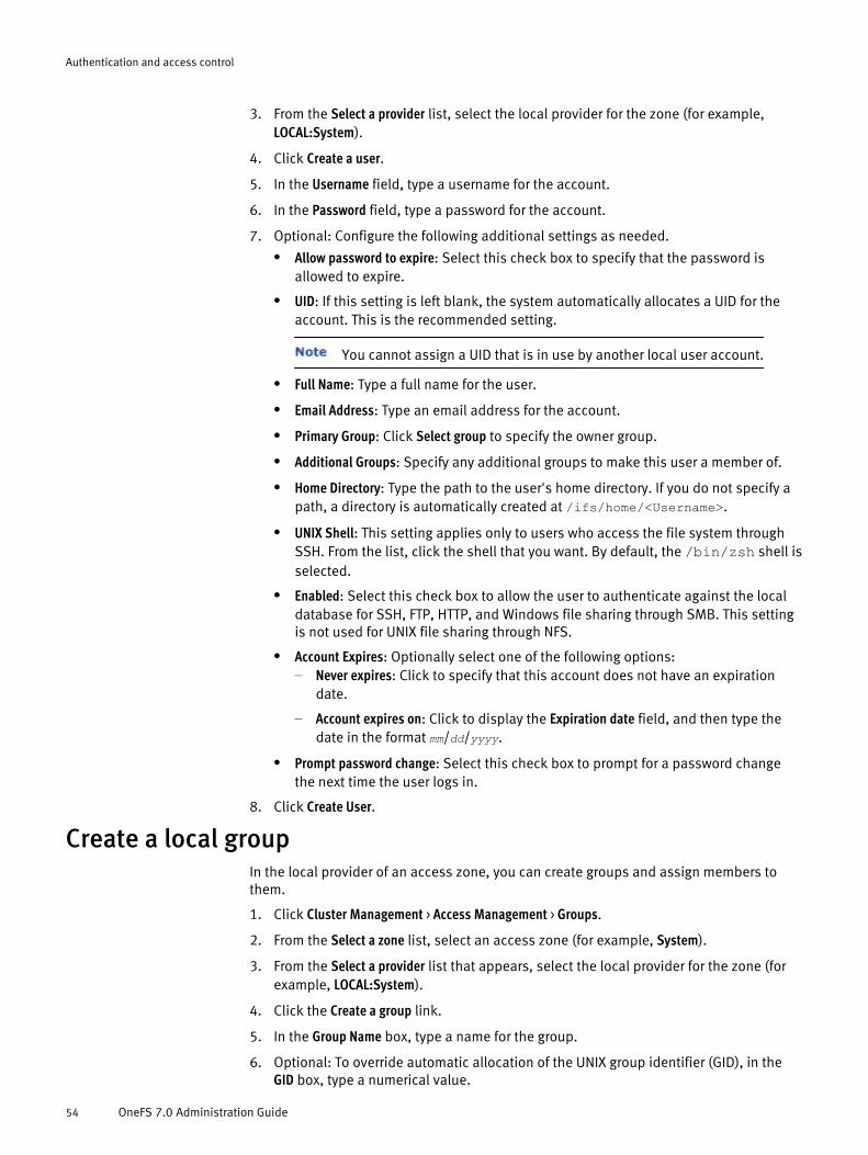
3. From the Select a provider list, select the local provider for the zone (for example,LOCAL:System).
4. Click Create a user.
5. In the Username field, type a username for the account.
6. In the Password field, type a password for the account.
7. Optional: Configure the following additional settings as needed.l Allow password to expire: Select this check box to specify that the password is
allowed to expire.
l UID: If this setting is left blank, the system automatically allocates a UID for theaccount. This is the recommended setting.
You cannot assign a UID that is in use by another local user account.
l Full Name: Type a full name for the user.
l Email Address: Type an email address for the account.
l Primary Group: Click Select group to specify the owner group.
l Additional Groups: Specify any additional groups to make this user a member of.
l Home Directory: Type the path to the user's home directory. If you do not specify apath, a directory is automatically created at /ifs/home/<Username>.
l UNIX Shell: This setting applies only to users who access the file system throughSSH. From the list, click the shell that you want. By default, the /bin/zsh shell isselected.
l Enabled: Select this check box to allow the user to authenticate against the localdatabase for SSH, FTP, HTTP, and Windows file sharing through SMB. This settingis not used for UNIX file sharing through NFS.
l Account Expires: Optionally select one of the following options:– Never expires: Click to specify that this account does not have an expiration
date.
– Account expires on: Click to display the Expiration date field, and then type thedate in the format mm/dd/yyyy.
l Prompt password change: Select this check box to prompt for a password changethe next time the user logs in.
8. Click Create User.
Create a local groupIn the local provider of an access zone, you can create groups and assign members tothem.
1. Click Cluster Management > Access Management > Groups.
2. From the Select a zone list, select an access zone (for example, System).
3. From the Select a provider list that appears, select the local provider for the zone (forexample, LOCAL:System).
4. Click the Create a group link.
5. In the Group Name box, type a name for the group.
6. Optional: To override automatic allocation of the UNIX group identifier (GID), in theGID box, type a numerical value.
Authentication and access control
54 OneFS 7.0 Administration Guide

You cannot assign a GID that is in use by another group. It is recommendedthat you leave this field blank to allow the system to automatically generate the GID.
7. Optional: Follow these steps for each member that you want to add the group:a. For the Members setting, click Add user. The Select a User dialog box appears.
b. For the Search for setting, select either Users or Well-known SIDs.
c. If you selected Users, specify values for the following fields:
– Username: Type all or part of a user name, or leave the field blank to return allusers. Wildcard characters are accepted.
– Access Zone: Select the access zone that contains the authentication providerthat you want to search.
– Provider: Select an authentication provider.
d. Click Search.
e. In the Search Results table, select a user and then click Select.The dialog box closes.
8. Click Create.
Managing users and groupsYou can view the users and groups of any authentication provider. You can create,modify, and delete users and groups in the local provider only.
Modify a local userYou can modify any setting for a local user account except the user name.
1. Click Cluster Management > Access Management > Users.
2. From the Select a zone list, select an access zone (for example, System).
3. From the Select a provider list, select the local provider for the access zone (forexample, LOCAL:System).
4. In the list of users, click View details for the local user whose settings you want tomodify.
5. For each setting that you want to modify, click Edit, make the change, and then clickSave.
6. Click Close.
Modify a local groupYou can add or remove members from a local group.
1. Click Cluster Management > Access Management > Groups.
2. From the Select a zone list, select an access zone (for example, System).
3. From the Select a provider list, select the local provider for the access zone (forexample, LOCAL:System).
4. In the list of groups, click View details for the local group whose settings you want tomodify.
5. For the Members setting, click Edit.
6. Add or remove the users that you want, and then click Save.
Authentication and access control
Managing users and groups 55

7. Click Close.
Delete a local userA deleted user can no longer access the cluster through the command-line interface, webadministration interface, or file access protocol. When you delete a local user account, itshome directory remains in place.
1. Click Cluster Management > Access Management > Users.
2. From the Select a zone list, select an access zone (for example, System).
3. From the Select a provider list, select the local provider for the zone (for example,LOCAL:System).
4. Click Delete for the user that you want to delete.
5. In the confirmation dialog box, click Delete.
Delete a local groupYou can delete a local group even if members are assigned to it; deleting a group doesnot affect the members of that group.
1. Click Cluster Management > Access Management > Groups.
2. From the Select a zone list, select an access zone (for example, System).
3. From the Select a provider list, select the local provider for the zone (for example,LOCAL:System).
4. Click Delete for the group that you want to delete.
5. In the confirmation dialog box, click Delete.
Creating file providersYou can create one or more file providers, each with its own combination of replacementfiles, for each access zone. Password database files, which are also called userdatabases files, must be in binary format.
Create a file providerYou can specify replacement files for any combination of users, groups, and netgroups.
1. Click Cluster Management > Access Management > File Provider.
2. Click Add a file provider.
3. In the File Provider Name field, type a name for the file provider.
4. Optional: Specify one or more replacement files by typing or browsing to theirlocations:l Users File: The full path to the spwd.db replacement file.
l Groups File: The full path to the group replacement file.
l Netgroups File: The full path to the netgroup replacement file.
5. Optional: To enable this provider to authenticate users, select the Authenticate usersfrom this provider check box.
6. Optional: To specify a home directory naming template, in the Home Directory Namingfield, type the full directory path that will contain all home directories.
Authentication and access control
56 OneFS 7.0 Administration Guide

7. Optional: To automatically create home directories for users the next time they log in,select the Create home directories on first login check box.
8. Optional: From the UNIX Shell list, select the shell that will be used when users accessthe file system through SSH.
9. Click Add File Provider.
Generate a password fileA file provider requires a password database file that is in binary format. To generate abinary password file, you must use the pwd_mkdb utility in the command-line interface(CLI).
1. Establish an SSH connection to any node in the cluster.
2. Run the following command, where -d <directory> specifies the location to store thespwd.db file and <file> specifies the location of the source password file:pwd_mkdb -d <directory> <file>
If you omit the -d option, the file is created in the /etc directory. For fullcommand usage, view the manual ("man") page by running the man pwd_mkdbcommand.
The following command generates an spwd.db file in the /ifs directory from a passwordfile located at /ifs/test.passwd:pwd_mkdb -d /ifs /ifs/test.passwd
What to do nextTo use the spwd.db file, when creating or modifying a file provider using the webadministration interface, specify its full path in the Users File setting.
Managing file providersEach file provider pulls directly from up to three replacement database files: a group filethat uses the same format as /etc/group; a netgroups file; and a binary password file,spwd.db, which provides fast access to the data in a file that uses the /etc/master.passwd format. You must copy the replacement files to the cluster and referencethem by their directory path.
If the replacement files are located outside the /ifs directory tree, you mustmanually distribute them to every node in the cluster. Changes that are made to thesystem provider's files are automatically distributed across the cluster.
Modify a file providerYou can modify any setting for a file provider, including its name.
1. Click Cluster Management > Access Management > File Provider.
2. In the File Providers table, click View details for the provider whose settings you want tomodify.
3. For each setting that you want to modify, click Edit, make the change, and then clickSave.
4. Click Close.
Authentication and access control
Generate a password file 57
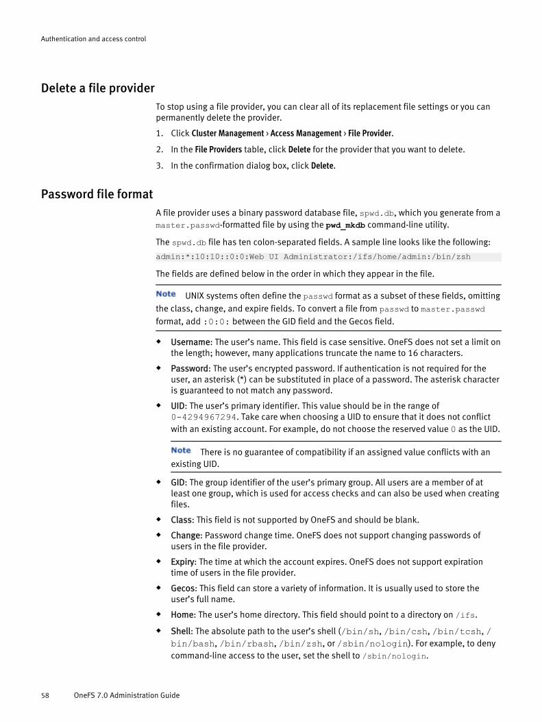
Delete a file providerTo stop using a file provider, you can clear all of its replacement file settings or you canpermanently delete the provider.
1. Click Cluster Management > Access Management > File Provider.
2. In the File Providers table, click Delete for the provider that you want to delete.
3. In the confirmation dialog box, click Delete.
Password file formatA file provider uses a binary password database file, spwd.db, which you generate from amaster.passwd-formatted file by using the pwd_mkdb command-line utility.
The spwd.db file has ten colon-separated fields. A sample line looks like the following:
admin:*:10:10::0:0:Web UI Administrator:/ifs/home/admin:/bin/zsh
The fields are defined below in the order in which they appear in the file.
UNIX systems often define the passwd format as a subset of these fields, omittingthe class, change, and expire fields. To convert a file from passwd to master.passwdformat, add :0:0: between the GID field and the Gecos field.
u Username: The user’s name. This field is case sensitive. OneFS does not set a limit onthe length; however, many applications truncate the name to 16 characters.
u Password: The user’s encrypted password. If authentication is not required for theuser, an asterisk (*) can be substituted in place of a password. The asterisk characteris guaranteed to not match any password.
u UID: The user’s primary identifier. This value should be in the range of0-4294967294. Take care when choosing a UID to ensure that it does not conflictwith an existing account. For example, do not choose the reserved value 0 as the UID.
There is no guarantee of compatibility if an assigned value conflicts with anexisting UID.
u GID: The group identifier of the user’s primary group. All users are a member of atleast one group, which is used for access checks and can also be used when creatingfiles.
u Class: This field is not supported by OneFS and should be blank.
u Change: Password change time. OneFS does not support changing passwords ofusers in the file provider.
u Expiry: The time at which the account expires. OneFS does not support expirationtime of users in the file provider.
u Gecos: This field can store a variety of information. It is usually used to store theuser’s full name.
u Home: The user’s home directory. This field should point to a directory on /ifs.
u Shell: The absolute path to the user’s shell (/bin/sh, /bin/csh, /bin/tcsh, /bin/bash, /bin/rbash, /bin/zsh, or /sbin/nologin). For example, to denycommand-line access to the user, set the shell to /sbin/nologin.
Authentication and access control
58 OneFS 7.0 Administration Guide

Group file formatThe file provider uses the format of the /etc/group file found on most UNIX systems.
The group file uses four colon-separated fields. A sample line looks like the following:
admin:*:10:root,admin
The fields are defined below in the order in which they appear in the file.
u Group name: The group’s name. This field is case sensitive. Although OneFS does notset a limit on the length of the group name, many applications truncate the name to16 characters.
u Password: This field is not supported by OneFS and should be set as an asterisk (*).
u GID: The group identifier. This value should be in the range of 0-4294967294. Becareful when choosing a GID to ensure that it does not conflict with an existing group.
u Group members: A comma-delimited list of user names that make up the group’smembers.
Netgroup file formatA netgroup file consists of one or more netgroups, each of which can contain members.Members of a netgroup can be hosts, users, or domains specified in a member triple. Anetgroup can also contain another netgroup.
Each entry in a netgroup file consists of the netgroup name, followed by a space-delimited set of member triples and nested netgroup names. A nested netgroup must bedefined somewhere else in the file.
A member triple takes the form (host, user, domain), where host is a machine,user is a username, and domain is a domain. Any combination is valid except an emptytriple (,,).
A sample file looks like the following:
rootgrp (myserver, root, somedomain.com) othergrp (someotherserver, root, somedomain.com) othergrp (other-win,, somedomain.com) (other-linux,, somedomain.com)
In this sample file, if you use rootgrp you get all four hosts; if you use othergrp you getonly the last two.
A new line signifies a new netgroup. For long netgroup entries, you can type abackslash character (\) in the right-most position of a line to indicate line continuation.
Create an Active Directory providerYou can configure multiple Active Directory domains, each with its own configurationsettings. You can join each access zone to an Active Directory domain.
1. Click Cluster Management > Access Management > Active Directory.
2. Click Join a domain.
3. In the Domain Name field, type a fully-qualified Active Directory domain name. Thisname will be used as the provider name
4. In the User field, type the username of an account that is authorized to join the ActiveDirectory domain.
5. In the Password field, type the password for the account.
Authentication and access control
Group file format 59

6. Optional: In the Organizational Unit field, type the organizational unit (OU) to connectto on the Active Directory server.
7. Optional: In the Machine Account field, type the name of the machine account.
Joining the domain will fail if the machine account exists but resides in adifferent organizational unit than the one you specified.
8. Optional: To enable Active Directory authentication for NFS, select the Enable SecureNFS check box. If you enable this setting, OneFS registers NFS service principal names(SPNs) during the domain join.
9. Optional: Click Advanced Active Directory Settings to configure advanced settings.
10. Click Join.
Managing Active Directory providersYou can view, modify, and delete Active Directory providers. OneFS includes a Kerberosconfiguration file for Active Directory in addition to the global Kerberos configuration file,both of which you can configure through the command-line interface.
Modify an Active Directory providerYou can modify the advanced settings for an Active Directory provider.
1. Click Cluster Management > Access Management > Active Directory.
2. In the list of Active Directory providers, click View details for the provider whosesettings you want to modify.
3. Click Advanced Active Directory Settings.
4. For each setting that you want to modify, click Edit, make the change, and then clickSave.
5. Optional: Click Close.
Delete an Active Directory providerWhen you delete an Active Directory provider, you disconnect the cluster from the ActiveDirectory domain that is associated with the provider, disrupting service for users whoare accessing it. After you leave an Active Directory domain, users can no longer accessthe domain from the cluster.
1. Click Cluster Management > Access Management > Active Directory.
2. In the Active Directory Providers table, click Leave for the domain you want to leave.
3. In the confirmation dialog box, click Leave.
Configure Kerberos settingsKerberos 5 protocol configuration is supported through the command line only.
In addition to the global Kerberos configuration file, OneFS includes a Kerberosconfiguration file for Active Directory. You can modify either file by following thisprocedure.
Authentication and access control
60 OneFS 7.0 Administration Guide

Most settings require modification only if you are using a Kerberos KeyDistribution Center (KDC) other than Active Directory—for example, if you are using an MITKDC for NFS version 3 or version 4 authentication.
1. Establish an SSH connection to any node in the cluster.
2. Run the isi auth krb5 command with the add, modify, or delete sub-command tospecify which entries to modify in the Kerberos configuration file.
For usage information, see the OneFS Command Reference.
3. Propagate the changes to the Kerberos configuration file by running the isi authkrb5 write command.
By default, changes are written to the global Kerberos configuration file, /etc/krb5.conf. To update the Kerberos configuration file for Active Directory, usethe --path option to specify the /etc/likewise-krb5-ad.conf file.
Active Directory provider settingsYou can view or modify the settings for an Active Directory provider.
Setting Description- -Services For UNIX Specifies whether to support RFC 2307
attributes for domain controllers. RFC 2307 isrequired for Windows UNIX Integration andServices For UNIX technologies.
Map user/group into primary domain Enables the lookup of unqualified user namesin the primary domain. If this setting is notenabled, the primary domain must be specifiedfor each authentication operation.
Ignore Trusted Domains Ignores all trusted domains.
Trusted Domains Specifies trusted domains to include if IgnoreTrusted Domains is set to Yes.
Domains to Ignore Specifies trusted domains to ignore even if
Ignore Trusted Domains is set to No.
Offline Alerts Sends an alert if the domain goes offline.
Enhanced Privacy Encrypts communication to and from thedomain controller.
Home Directory Naming Specifies the path to use as the home directorynaming template.
Create Home Directory Creates a home directory the first time a userlogs in.
UNIX Shell Specifies the path to the UNIX login shell.
Lookup User Looks up Active Directory users in all otherproviders before allocating a UID.
Authentication and access control
Active Directory provider settings 61
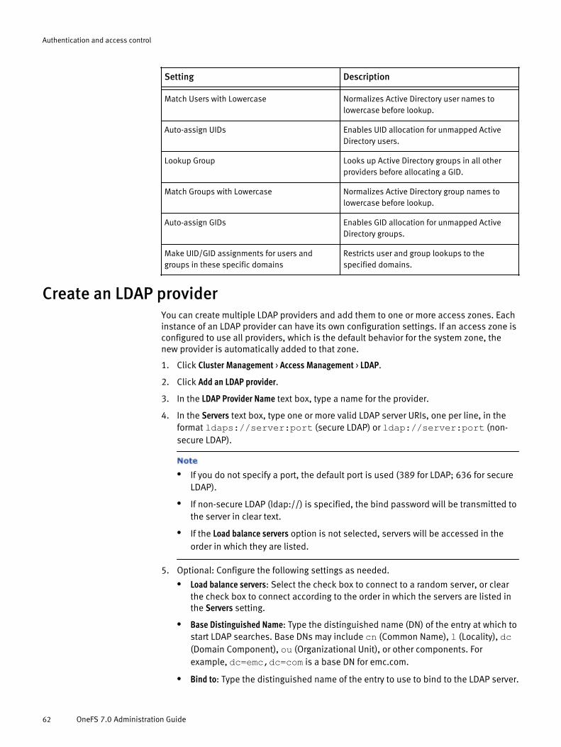
Setting Description- -Match Users with Lowercase Normalizes Active Directory user names to
lowercase before lookup.
Auto-assign UIDs Enables UID allocation for unmapped ActiveDirectory users.
Lookup Group Looks up Active Directory groups in all otherproviders before allocating a GID.
Match Groups with Lowercase Normalizes Active Directory group names tolowercase before lookup.
Auto-assign GIDs Enables GID allocation for unmapped ActiveDirectory groups.
Make UID/GID assignments for users andgroups in these specific domains
Restricts user and group lookups to thespecified domains.
Create an LDAP providerYou can create multiple LDAP providers and add them to one or more access zones. Eachinstance of an LDAP provider can have its own configuration settings. If an access zone isconfigured to use all providers, which is the default behavior for the system zone, thenew provider is automatically added to that zone.
1. Click Cluster Management > Access Management > LDAP.
2. Click Add an LDAP provider.
3. In the LDAP Provider Name text box, type a name for the provider.
4. In the Servers text box, type one or more valid LDAP server URIs, one per line, in theformat ldaps://server:port (secure LDAP) or ldap://server:port (non-secure LDAP).
l If you do not specify a port, the default port is used (389 for LDAP; 636 for secureLDAP).
l If non-secure LDAP (ldap://) is specified, the bind password will be transmitted tothe server in clear text.
l If the Load balance servers option is not selected, servers will be accessed in theorder in which they are listed.
5. Optional: Configure the following settings as needed.l Load balance servers: Select the check box to connect to a random server, or clear
the check box to connect according to the order in which the servers are listed inthe Servers setting.
l Base Distinguished Name: Type the distinguished name (DN) of the entry at which tostart LDAP searches. Base DNs may include cn (Common Name), l (Locality), dc(Domain Component), ou (Organizational Unit), or other components. Forexample, dc=emc,dc=com is a base DN for emc.com.
l Bind to: Type the distinguished name of the entry to use to bind to the LDAP server.
Authentication and access control
62 OneFS 7.0 Administration Guide

l Password: Specify the password to use when binding to the LDAP server. Use ofthis password does not require a secure connection; if the connection is not usingTLS the password will be sent in clear text.
6. Optional: Click Default Query Settings to configure the following additional settings.l Distinguished Name: Type the distinguished name of the entry at which to start
LDAP searches.
l Search Scope: Defines the default depth from the base DN to perform LDAPsearches.Click to select one of the following values:
– base: Search only the entry at the base DN.
– onelevel: Search all entries exactly one level below the base DN.
– subtree: Search the base DN and all entries below it.
– children: Search all entries below the base DN, excluding the base DN itself.
l Search Timeout: Type the number of seconds after which a search will not be retriedand will fail. The default value is 100.
7. Optional: Click User Query Settings to configure the following additional settings.l Distinguished Name: Type the distinguished name of the entry at which to start
LDAP searches for users.
l Search Scope: Defines the depth from the base DN to perform LDAP searches forusers.Click to select one of the following values:
– default: Use the setting defined in the default query settings.
– base: Search only the entry at the base DN.
– onelevel: Search all entries exactly one level below the base DN.
– subtree: Search the base DN and all entries below it.
– children: Search all entries below the base DN, excluding the base DN itself.
l Query Filter: Sets the LDAP filter for user objects.
l Authenticate users from this provider: Select the check box to enable the provider torespond to authentication requests, or clear the check box to prevent respondingto authentication requests.
l Home Directory Naming: Type the full path to the location on /ifs to create homedirectories.
l Create home directories on first login: Select the check box to automatically create ahome directory when a user logs in, if one does not already exist for the user.
l UNIX Shell: Click to select a login shell from the list. This setting applies only tousers who access the file system through SSH.
8. Optional: Click Group Query Settings to configure the following additional settings.l Distinguished Name: Type the distinguished name of the entry at which to start
LDAP searches for groups.
l Search Scope: Defines the depth from the base DN to perform LDAP searches forgroups.Click to select one of the following values:
– default: Use the setting defined in the default query settings.
– base: Search only the entry at the base DN.
Authentication and access control
Create an LDAP provider 63
– onelevel: Search all entries exactly one level below the base DN.
– subtree: Search the base DN and all entries below it.
– children: Search all entries below the base DN, excluding the base DN itself.
l Query Filter: Sets the LDAP filter for group objects.
9. Optional: Click Netgroup Query Settings to configure the following additional settings.l Distinguished Name: Type the distinguished name of the entry at which to start
LDAP searches for netgroups.
l Search Scope: Defines the depth from the base DN to perform LDAP searches fornetgroups.Click to select one of the following values:
– default: Use the setting defined in the default query settings.
– base: Search only the entry at the base DN.
– onelevel: Search all entries exactly one level below the base DN.
– subtree: Search the base DN and all entries below it.
– children: Search all entries below the base DN, excluding the base DN itself.
l Query Filter: Sets the LDAP filter for netgroup objects.
10. Optional: Click Advanced LDAP Settings to configure the following additional settings.l Name Attribute: Specifies the LDAP attribute that contains UIDs, which are used as
login names. The default value is uid.
l Common Name Attribute: Specifies the LDAP attribute that contains common names.The default value is cn.
l Email Attribute: Specifies the LDAP attribute that contains email addresses. Thedefault value is email.
l GECOS Field Attribute: Specifies the LDAP attribute that contains GECOS fields. Thedefault value is gecos.
l UID Attribute: Specifies the LDAP attribute that contains UID numbers. The defaultvalue is uidNumber.
l GID Attribute: Specifies the LDAP attribute that contains GIDs. The default value isgidNumber.
l Home Directory Attribute: Specifies the LDAP attribute that contains homedirectories. The default value is homeDirectory.
l UNIX Shell Attribute: Specifies the LDAP attribute that contains UNIX login shells.The default value is loginShell.
l Netgroup Members Attribute: Specifies the LDAP attribute that contains netgroupmembers. The default value is memberNisNetgroup.
l Netgroup Triple Attribute: Specifies the LDAP attribute that contains netgrouptriples. The default value is nisNetgroupTriple.
l Group Members Attribute: Specifies the LDAP attribute that contains groupmembers. The default value is memberUid.
l Unique Group Members Attribute: Specifies the LDAP attribute that contains uniquegroup members. This determines what groups a user is a member of if the LDAPserver is queried by the user’s DN instead of the user’s name. This setting has nodefault value.
Authentication and access control
64 OneFS 7.0 Administration Guide

l UNIX Password Attribute: Specifies the LDAP attribute that contains UNIXpasswords. This setting has no default value.
l Windows Password Attribute: Specifies the LDAP attribute that contains Windowspasswords. The default value is ntpasswdhash.
l Certificate Authority File: Specifies the full path to the root certificates file.
l Require secure connection for passwords: Specifies whether to require a TLSconnection.
l Ignore TLS Errors: Continues over a secure connection even if identity checks fail.
11. Click Add LDAP provider.
Managing LDAP providersYou can view, modify, and delete LDAP providers or you can stop using an LDAP providerby removing it from all access zones that are using it.
Modify an LDAP providerYou can modify any setting for an LDAP provider except its name. You must specify atleast one server for the provider to be enabled.
1. Click Cluster Management > Access Management > LDAP.
2. In the list of LDAP providers, click View details for the provider whose settings youwant to modify.
3. For each setting that you want to modify, click Edit, make the change, and then clickSave.
4. Optional: Click Close.
Delete an LDAP providerWhen you delete an LDAP provider, it is removed from all access zones. As an alternative,you can stop using an LDAP provider by removing it from each access zone that containsit so that the provider remains available for future use.
1. Click Cluster Management > Access Management > LDAP.
2. Click Delete for the provider that you want to delete.
3. In the confirmation dialog box, click Delete.
Create a NIS providerYou can create multiple NIS providers and add them to one or more access zones. Eachinstance of a NIS provider can have its own configuration settings. If an access zone isconfigured to use all providers, which is the default behavior for the system zone, thenew provider is automatically added to the zone.
1. Click Cluster Management > Access Management > NIS.
2. Click Add a NIS provider.
3. In the NIS Provider Name field, type a name for the provider.
4. In the Servers text box, type one or more valid IP addresses, host names, or fullyqualified domain names, separated by commas.
Authentication and access control
Managing LDAP providers 65

If the Load balance servers option is not selected, servers will be accessed inthe order in which they are listed.
5. Optional: For the Load balance servers setting, click the check box to connect to arandom server, or clear the check box to connect according to the order in which theservers are listed in the Servers setting.
6. Optional: Click Default Query Settings to configure the following additional settings.l NIS Domain: Type the NIS domain name.
l Search Timeout: Type the number of seconds after which a search will not be retriedand will fail. The default value is 100.
l Retry Frequency: Type the number of seconds after which a search will be retried.The default value is 5.
7. Optional: Click User Query Settings to configure the following additional settings.l Authenticate users from this provider: Select the check box to enable this provider to
respond to authentication requests, or clear the check box to prevent respondingto authentication requests.
l Home Directory Naming: Type the full path to the location on /ifs to create homedirectories.
l Create home directories on first login: Select the check box to automatically create ahome directory when a user logs in, if one does not already exist for the user.
l UNIX Shell: Click to select a shell from the list. This setting applies only to userswho access the file system through SSH.
8. Optional: Click Host Name Query Settings to configure the following additional settings.l Resolve Hosts: Select the check box to resolve hosts, or clear the check box to
specify not to resolve hosts.
9. Click Add NIS provider.
Managing NIS providersYou can view and modify NIS providers or delete providers that are no longer needed. Asan alternative to deleting a NIS provider, you can remove it from any access zones thatare using it.
Modify a NIS providerYou can modify any setting for a NIS provider except its name. You must specify at leastone server for the provider to be enabled.
1. Click Cluster Management > Access Management > NIS.
2. In the list of NIS providers, click View details for the provider whose settings you wantto modify.
3. For each setting that you want to modify, click Edit, make the change, and then clickSave.
4. Click Close.
Authentication and access control
66 OneFS 7.0 Administration Guide

Delete a NIS providerWhen you delete a NIS provider, it is removed from all access zones. As an alternative,you can stop using a NIS provider by removing it from each access zone that contains itso that the provider remains available for future use.
1. Click Cluster Management > Access Management > NIS.
2. Click Delete for the provider that you want to delete.
3. In the confirmation dialog box, click Delete.
Create an access zoneWhen you create an access zone, you can add one or more authentication providerinstances, user mapping rules, and SMB shares, or you can create an empty access zoneand configure it later.
1. Click Cluster Management > Access Management > Access Zones.
2. Click Create an access zone.
3. In the Access Zone Name field, type a name for the access zone.
4. Optional: In the Authentication Providers list, click one of the following options:l Use all authentication providers: Adds an instance of each available provider to the
access zone.
l Manually select authentication providers: Allows you to select one or more providerinstances to add to the access zone. Follow these steps for each provider instancethat you want to add:a. Click Add an authentication provider.
b. In the Authentication Provider Type list, select a provider type. A provider type islisted only if an instance of that type exists and is not already in use by theaccess zone.
c. In the Authentication Provider list, select an available provider instance.
d. If you are finished adding provider instances, you can change the priority inwhich they are called by changing the order in which they are listed. To do so,click the title bar of a provider instance and drag it up or down to a newposition in the list.
5. Optional: In the User Mapping Rules list, follow these steps for each user mapping rulethat you want to add:
a. Click Create a user mapping rule. The User Mapping Rules table appears and displaysthe Create a User Mapping Rule form.
b. In the Operation list, click to select one of the following operations:– Append fields from a user: Modifies a token by adding specified fields to it. All
appended identifiers become members of the additional groups list.
– Insert fields from a user: Modifies a token by adding specified fields fromanother token. An inserted primary user or group becomes the new primaryuser or group in the token and moves the old primary user or group to theadditional identifiers list. Modifying the primary user leaves the token’susername unchanged. When inserting additional groups from a token, the newgroups are added to the existing groups.
– Replace a user with a new user: Replaces a token with the token identified byanother user. If another user is not specified, the token is removed from the
Authentication and access control
Delete a NIS provider 67

list and no user is inserted to replace it. If there are no tokens in the list,access is denied with a "no such user" error.
– Remove supplemental groups from a user: Modifies a token by removing thesupplemental groups.
– Join two users together: Inserts the new token into the list of tokens. If the newtoken is the second user, it is inserted after the existing token; otherwise, it isinserted before the existing token. The insertion point is primarily relevantwhen the existing token is already the first in the list because the first token isused to determine the ownership of new system objects.
c. Fill in the fields as needed.
Available fields differ depending on the selected operation.
d. Click Add Rule.
e. If you are finished adding user mapping rules, you can change the priority inwhich they are called by changing the order in which they are listed. To do so,click the title bar of a rule and drag it up or down to a new position in the list.
To ensure that each rule gets processed, it is recommended that you listreplacements first and allow/deny rules last.
6. Optional: For the SMB Shares setting, select one of the following options:l Use no SMB shares: Ignores all SMB shares.
l Use all SMB shares: Adds each available SMB share to the access zone.
l Manually select SMB shares: Allows you to select the SMB shares to add to theaccess zone. The following additional steps are required:a. Click Add SMB shares. The Select SMB Shares dialog box appears.
b. Select the check box for each SMB share that you want to add to the accesszone.
c. Click Select.
7. Click Create Access Zone.
What to do nextBefore you can use an access zone, you must associate it with an IP address pool. See"Associate an IP address pool with an access zone."
Managing access zonesYou can configure the authentication providers, SMB namespace, and user mappingrules for any access zone. You can modify the name of any zone except the system zone.
Modify an access zoneYou can modify the authentication providers, SMB shares, and user mapping rules for anaccess zone. You can modify the name of any access zone except the system zone.
1. Click Cluster Management > Access Management > Access Zones.
2. Click View details for the access zone whose settings you want to modify.
3. For each setting that you want to modify, click Edit, make the change, and then clickSave.
Authentication and access control
68 OneFS 7.0 Administration Guide

Associate an IP address pool with an access zoneYou can specify which access zone to use according to the IP address that a user isconnecting to.
1. Click Cluster Management -> Network Configuration.
2. In the External Network Settings section, under Subnets, click a subnet name (forexample, subnet0).
3. In the IP Address Pools section, click the + icon if necessary to view the settings for apool.
4. Next to the Basic Settings heading, click Edit.The Configure IP Pool dialog box appears.
5. For the Access zone setting, select the zone to use when connecting through an IPaddress that belongs to this pool.
6. Click Submit.
Delete an access zoneYou can delete any access zone except the built-in system zone. When you delete anaccess zone, any associated authentication provider instances or SMB shares remainavailable to other zones.
1. Click Cluster Management > Access Management > Access Zones.
2. Click Delete for the zone that you want to delete.
3. In the confirmation dialog box, click Delete.
Authentication and access control
Associate an IP address pool with an access zone 69

Authentication and access control
70 OneFS 7.0 Administration Guide
CHAPTER 3
File sharing
Multi-protocol support is built into the OneFS operating system, enabling a single file ordirectory to be accessed through SMB for Windows file sharing, NFS for UNIX file sharing,secure shell (SSH), FTP, and HTTP. By default, only the SMB and NFS protocols areenabled.
OneFS creates the /ifs directory, which is the root directory for all file system data onthe cluster. The /ifs directory is configured as an SMB share and an NFS export bydefault. You can create additional shares and exports within the /ifs directory tree.
You can set Windows- and UNIX-based permissions on OneFS files and directories. Userswho have the required permissions and administrative privileges can create, modify, andread data on the cluster through one or more of the supported file sharing protocols.
u SMB. Allows Microsoft Windows and Mac OS X clients to access files that are storedon the cluster.
u NFS. Allows UNIX, Linux, Mac OS X, Solaris, and other UNIX-based clients to accessfiles that are stored on the cluster.
u HTTP (with optional DAV). Allows clients to access files that are stored on the clusterthrough a web browser.
u FTP. Allows any client that is equipped with an FTP client program to access files thatare stored on the cluster through the FTP protocol.
u NFS.......................................................................................................................72u SMB......................................................................................................................72u HTTP......................................................................................................................72u FTP........................................................................................................................73u Mixed protocol environments................................................................................73u Write caching with SmartCache.............................................................................73u Create an NFS export.............................................................................................75u Create an SMB share.............................................................................................75u Configure NFS file sharing.....................................................................................76u Configure SMB file sharing....................................................................................80u Configure and enable HTTP file sharing..................................................................83u Configure and enable FTP file sharing....................................................................84u Managing NFS exports...........................................................................................84u Managing SMB shares...........................................................................................86
File sharing 71
NFSNFS exports provide UNIX clients network access to file system resources on the cluster.OneFS includes a configurable NFS service that enables you to create and manage NFSexports.
OneFS supports asynchronous and synchronous communication over NFS.
The OneFS cluster supports the following authentication providers for NFS file sharing.
u Network Information Service (NIS). NIS is a client/server directory service protocol fordistributing system configuration data, such as user and host names, betweencomputers on a network.
u Lightweight Directory Access Protocol (LDAP). LDAP is an application protocol forquerying and modifying directory services running over TCP/IP.
SMBSMB shares provide Windows clients network access to file system resources on thecluster. OneFS includes a configurable SMB service that enables you to create andmanage SMB shares. You can grant permissions to users and groups to carry outoperations such as reading, writing, and setting access permissions on SMB shares.
The /ifs directory is configured as an SMB share and enabled by default. OneFSsupports the "user" and "anonymous" security modes. If the "user" security mode isenabled, when you connect to a share from an SMB client you must provide a valid username with proper credentials.
The SMB protocol uses security identifiers (SIDs) exclusively for authorization data. Allidentities are converted to SIDs during retrieval and are converted back to their on-diskrepresentation before storage.
When a file or directory is created, OneFS checks the access control list (ACL) of its parentdirectory. If any inheritable access control entries (ACEs) are found, a new ACL isgenerated from those ACEs. If no inheritable ACEs are found, a default ACL is created fromthe combined file and directory create mask / create mode settings.
OneFS supports the following SMB clients:
u SMB 1 in Windows 2000/ Windows XP and later.
u SMB 1 in Mac OS X 10.5 and later.
u SMB 2 in Windows Vista/ Windows Server 2008 and later.
u SMB 2.1 in Windows 7/ Windows Server 2008 R2 and later.
HTTPOneFS includes a configurable HTTP service, which it uses to request files that are storedon the cluster and to interact with the web administration interface.
OneFS supports the Distributed Authoring and Versioning (DAV) service to enablemultiple users to manage and modify files. DAV is a set of extensions to HTTP that allowsclients to read and write from the cluster through the HTTP protocol. You can enable DAVin the web administration interface.
OneFS supports a form of the web-based DAV (WebDAV) protocol that enables users tomodify and manage files on remote web servers. OneFS performs distributed authoring,but does not support versioning and does not perform security checks.
Each node in the cluster runs an instance of the Apache HTTP Server to provide HTTPaccess. You can configure the HTTP service to run in different modes.
File sharing
72 OneFS 7.0 Administration Guide
FTPThe FTP service is disabled by default. You can enable the FTP service to allow any nodein the cluster to respond to FTP requests through a standard user account.
When configuring FTP access, make sure that the specified FTP root is the home directoryof the user who logs in. For example, the FTP root for local user "jsmith" should be ifs/home/jsmith.
You can enable the transfer of files between remote FTP servers and enable anonymousFTP service on the root by creating a local user named "anonymous" or "ftp".
Mixed protocol environmentsThe /ifs directory is the root directory for all file system data in the cluster, serving as anSMB share, an NFS export, and a document root directory. You can create additionalshares and exports within the /ifs directory tree. Although it is not recommended, theOneFS cluster can be configured to use SMB or NFS exclusively. Within these scenariosyou can also enable HTTP, FTP, and SSH.
Access rights are enforced consistently across access protocols regardless of the securitymodel. A user is granted or denied the same rights to a file when using SMB as they arewhen using NFS. Clusters running OneFS support a set of global policy settings thatenable you to customize the default access control list (ACL) and UNIX permissionssettings.
OneFS is configured with traditional UNIX permissions on the file tree. By using WindowsExplorer or OneFS administrative tools, any file or directory can be given an ACL. ACLs inOneFS can include local, NIS, and LDAP users and groups in addition to Windows domainusers and groups. After a file is given an ACL, its mode bits are no longer enforced, andexist only as an estimate of the effective permissions.
It is recommended that you only configure ACL and UNIX permissions if you fullyunderstand how they interact with one another.
Write caching with SmartCacheWrite caching accelerates the process of writing data to the cluster. OneFS includes awrite-caching feature called SmartCache, which is enabled by default for all files anddirectories.
If write caching is enabled, OneFS writes data to a write-back cache instead ofimmediately writing the data to disk. OneFS can write the data to disk at a time that ismore convenient.
It is recommended that you do not disable write caching for a file or directory andthat you enable write caching for all file pool policies.
OneFS interprets writes to the cluster as either synchronous or asynchronous, dependingon a client's specifications. The impacts and risks of write caching depend on whatprotocols clients use to write to the cluster, and whether the writes are interpreted assynchronous or asynchronous. If you disable write caching, client specifications areignored and all writes are performed synchronously.
The following table explains how clients' specifications are interpreted, according to theprotocol.
File sharing
FTP 73
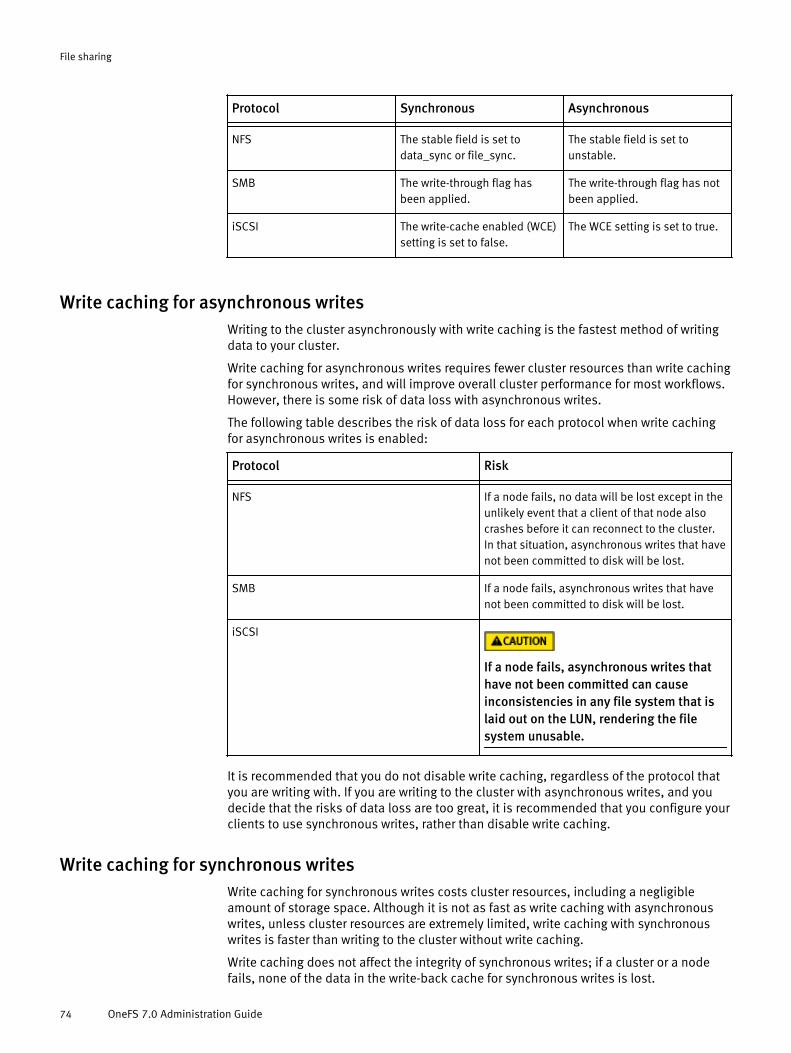
Protocol Synchronous Asynchronous- - -NFS The stable field is set to
data_sync or file_sync.The stable field is set tounstable.
SMB The write-through flag hasbeen applied.
The write-through flag has notbeen applied.
iSCSI The write-cache enabled (WCE)setting is set to false.
The WCE setting is set to true.
Write caching for asynchronous writesWriting to the cluster asynchronously with write caching is the fastest method of writingdata to your cluster.
Write caching for asynchronous writes requires fewer cluster resources than write cachingfor synchronous writes, and will improve overall cluster performance for most workflows.However, there is some risk of data loss with asynchronous writes.
The following table describes the risk of data loss for each protocol when write cachingfor asynchronous writes is enabled:
Protocol Risk- -NFS If a node fails, no data will be lost except in the
unlikely event that a client of that node alsocrashes before it can reconnect to the cluster.In that situation, asynchronous writes that havenot been committed to disk will be lost.
SMB If a node fails, asynchronous writes that havenot been committed to disk will be lost.
iSCSI
If a node fails, asynchronous writes thathave not been committed can causeinconsistencies in any file system that islaid out on the LUN, rendering the filesystem unusable.
It is recommended that you do not disable write caching, regardless of the protocol thatyou are writing with. If you are writing to the cluster with asynchronous writes, and youdecide that the risks of data loss are too great, it is recommended that you configure yourclients to use synchronous writes, rather than disable write caching.
Write caching for synchronous writesWrite caching for synchronous writes costs cluster resources, including a negligibleamount of storage space. Although it is not as fast as write caching with asynchronouswrites, unless cluster resources are extremely limited, write caching with synchronouswrites is faster than writing to the cluster without write caching.
Write caching does not affect the integrity of synchronous writes; if a cluster or a nodefails, none of the data in the write-back cache for synchronous writes is lost.
File sharing
74 OneFS 7.0 Administration Guide

Create an NFS exportOneFS does not restrict the number of NFS exports that you can create.
1. Click Protocols > UNIX Sharing (NFS) > NFS Export.
2. Click Add an Export.
3. Optional: In the Description text field, type a comment with basic information aboutthe export you are creating. There is a 255 character limit.
4. Optional: In the Clients text field, type the names of the clients that are allowed toaccess the specified directories. To export all clients, leave this field blank. You canspecify a client by host name, IP address, subnet, or netgroup. You can includemultiple clients in this field, in the form of one client entry per line.
5. Click Browse and select the file directory you want to export. Repeat this step to addas many directory paths as needed.
6. Specify export permissions:l Restrict actions to read-only.
l Enable mount access to subdirectories. Allow subdirectories below the path(s) tobe mounted.
7. Specify User/Group mapping. If you select the Custom Default option, you can limitaccess by mapping root users or all users to a specific user and/or group ID. For rootsquash, map the root user (UID 0) to the user name "nobody".
8. Select the security type for the export:l UNIX system.
l Kerberos5.
l Kerberos5 Integrity.
l Kerberos5 Privacy.
9. Configure Advanced NFS Export Settings.
10. Click Save.
Create an SMB shareWhen creating an SMB share, you can override default permissions, performance, andaccess settings. You can configure SMB home directory provisioning by using directorypath variables to automatically create and redirect users to their own home directories.
1. Click Protocols > Windows Sharing (SMB) > SMB Shares.
2. Click Add a share.
3. In the Share Name text field, type a name for the share.
Share names can contain up to 80 characters, and can only contain alphanumericcharacters, hyphens, and spaces.
4. In the Description text field, type a comment with basic information about the shareyou are creating. There is a 255 character limit.
A description is optional, but is helpful when managing multiple shares.
5. In the Directory to be Shared field, type the full path of the share, beginning with /ifs,or click Browse to locate the share.
The variables that can be used in the directory path are as follows:
File sharing
Create an NFS export 75

Variable Expansion- -%D NetBIOS domain name.
%U User name, for example user_001.
%Z Zone name, for example System.
%L Host name of the cluster, normalized tolowercase.
%0 First character of the user name.
%1 Second character of the user name.
%2 Third character of the user name.
For example, if a user in the domain named DOMAIN and with the username ofuser_1, the path /ifs/home/%D/%U is interpreted as /ifs/home/DOMAIN/user_1.
6. Apply the initial Directory ACLs settings. These settings can be modified later.l To maintain the existing permissions on the shared directory, click the Do not
change existing permissions option.
l To apply a default ACL to the shared directory, click the Apply Windows default ACLsoption.
l To maintain the existing permissions on the shared directory, click the Do notchange existing permissions option.
To apply a default ACL to the shared directory, click the Apply Windows defaultACLs option If the Auto-Create Directories setting is selected, an ACL with the equivalentof UNIX 700 mode bit permissions is created for any directory that is automaticallycreated.
7. Optional: If needed, apply the home directory provisioning options.l Select the Allow Variable Expansion option to expand path variables (%U, %L, %D,
and %Z) in the share directory path.
l Select the Auto-Create Directories option to automatically create directories whenusers access the share for the first time. This option can only be selected if AllowVariable Expansion has been applied.
Allow Variable Expansion is required for paths to be created automatically. IfAllow Variable Expansionis applied, but Auto-Create Directories is not, no paths will beautomatically created, and any expansion variables in the name will not beexpanded. For example: a new share named "home_share" is created with the path /ifs/%U/home. User "user_1" attempts to connect to "home_share", they will not beable to connect to the cluster and will see an error message.
8. If needed, apply the Users & Groups options.
9. If needed, apply advanced SMB share settings.
10. Click Create.
Configure NFS file sharingYou can enable or disable the NFS service, set the lock protection level, and set thesecurity type. These settings are applied across all nodes in the cluster. You can change
File sharing
76 OneFS 7.0 Administration Guide

the settings for individual NFS exports as you create them, or edit the settings forindividual exports as needed.
1. Click Protocols > UNIX Sharing (NFS) > NFS Settings.
2. Enable or disable the NFS service and version support settings:l NFS Service
l NFSv2 Support
l NFSv3 Support
l NFSv4 Support
3. Select the Lock Protection Level setting.
4. Click the Reload Cached Configuration button.The cached NFS export settings are reloaded to ensure that changes to DNS or NIS areapplied.
5. In the Users/Groups Mapping menu, click Custom Default. A box containing the settingsfor Map to User Credentials and Also map these user groups appears.a. To limit access by mapping root users or all users to a specific user or group, from
the Root users list, click Specific username and then type the user names in the textfield. A user is any user available in one of the configured authorization providers.
b. To map users to groups, select the Also map these users to groups check box, clickSpecific user group(s), and then type the group names in the text field.
6. Select the security type.
The default setting is UNIX.
7. Click Save.
Disable NFS file sharingOneFS supports multiple versions of NFS. You can disable support for NFSv2, NFSv3,NFSv4, or the entire NFS service.
1. Click Protocols > UNIX Sharing (NFS) > NFS Settings.
2. Click disable for the entire NFS service or for individual versions of the NFS protocol.
3. Click Save.
NFS service settingsThe NFS service settings are the global settings that determine how the NFS file sharingservice operates. These settings include versions of NFS to support, the lock protectionlevel, NFS exports configuration, user/group mappings, and security types.
Setting Description- -Service Enables or disables the NFS service. This
setting is enabled by default.
NFSv2 support Enables or disables support for NFSv2. Thissetting is enabled by default.
NFSv3 support Enables or disables support for NFSv3. Thissetting is enabled by default.
File sharing
Disable NFS file sharing 77
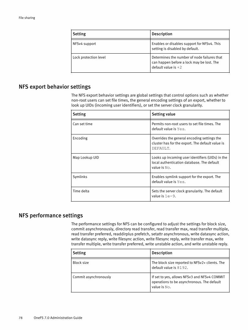
Setting Description- -NFSv4 support Enables or disables support for NFSv4. This
setting is disabled by default.
Lock protection level Determines the number of node failures thatcan happen before a lock may be lost. Thedefault value is +2
NFS export behavior settingsThe NFS export behavior settings are global settings that control options such as whethernon-root users can set file times, the general encoding settings of an export, whether tolook up UIDs (incoming user identifiers), or set the server clock granularity.
Setting Setting value- -Can set time Permits non-root users to set file times. The
default value is Yes.
Encoding Overrides the general encoding settings thecluster has for the export. The default value isDEFAULT.
Map Lookup UID Looks up incoming user identifiers (UIDs) in thelocal authentication database. The defaultvalue is No.
Symlinks Enables symlink support for the export. Thedefault value is Yes.
Time delta Sets the server clock granularity. The defaultvalue is 1e-9.
NFS performance settingsThe performance settings for NFS can be configured to adjust the settings for block size,commit asynchronously, directory read transfer, read transfer max, read transfer multiple,read transfer preferred, readdirplus prefetch, setattr asynchronous, write datasync action,write datasync reply, write filesync action, write filesync reply, write transfer max, writetransfer multiple, write transfer preferred, write unstable action, and write unstable reply.
Setting Description- -Block size The block size reported to NFSv2+ clients. The
default value is 8192.
Commit asynchronously If set to yes, allows NFSv3 and NFSv4 COMMIToperations to be asynchronous. The defaultvalue is No.
File sharing
78 OneFS 7.0 Administration Guide
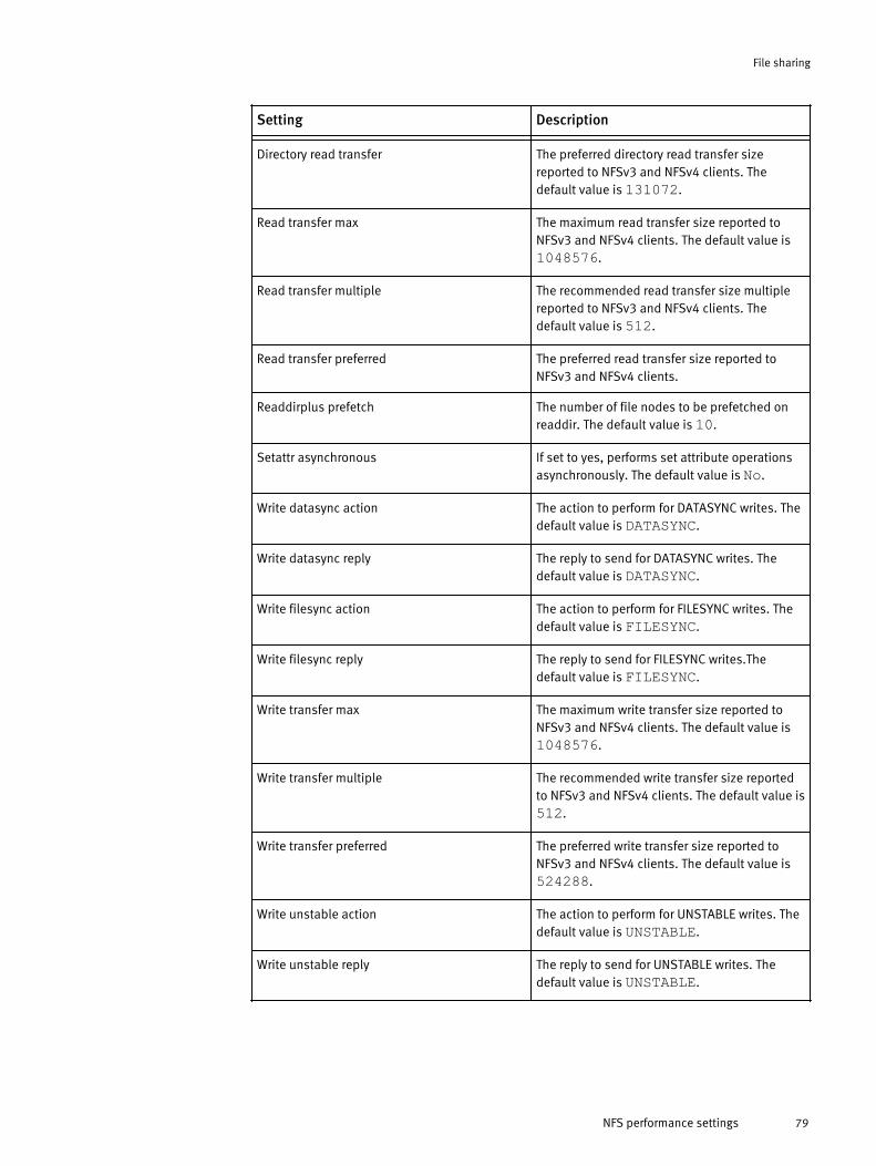
Setting Description- -Directory read transfer The preferred directory read transfer size
reported to NFSv3 and NFSv4 clients. Thedefault value is 131072.
Read transfer max The maximum read transfer size reported toNFSv3 and NFSv4 clients. The default value is1048576.
Read transfer multiple The recommended read transfer size multiplereported to NFSv3 and NFSv4 clients. Thedefault value is 512.
Read transfer preferred The preferred read transfer size reported toNFSv3 and NFSv4 clients.
Readdirplus prefetch The number of file nodes to be prefetched onreaddir. The default value is 10.
Setattr asynchronous If set to yes, performs set attribute operationsasynchronously. The default value is No.
Write datasync action The action to perform for DATASYNC writes. Thedefault value is DATASYNC.
Write datasync reply The reply to send for DATASYNC writes. Thedefault value is DATASYNC.
Write filesync action The action to perform for FILESYNC writes. Thedefault value is FILESYNC.
Write filesync reply The reply to send for FILESYNC writes.Thedefault value is FILESYNC.
Write transfer max The maximum write transfer size reported toNFSv3 and NFSv4 clients. The default value is1048576.
Write transfer multiple The recommended write transfer size reportedto NFSv3 and NFSv4 clients. The default value is512.
Write transfer preferred The preferred write transfer size reported toNFSv3 and NFSv4 clients. The default value is524288.
Write unstable action The action to perform for UNSTABLE writes. Thedefault value is UNSTABLE.
Write unstable reply The reply to send for UNSTABLE writes. Thedefault value is UNSTABLE.
File sharing
NFS performance settings 79

NFS client compatibility settingsThe NFS client compatibility settings are global settings that affect the customization ofNFS exports. These settings include the maximum file size, enabling readdirplus, and 32-bit file IDs.
Setting Setting value- -Max file size Specifies the maximum file size to allow. The
default value is 9223372036854776000.
Readdirplus enable Enables readdirplus. The default value is yes.
Return 32 bit file IDs Returns 32-bit file IDs.
Configure SMB file sharingYou can configure the global settings for SMB, including SMB server, snapshots directory,SMB share, file and directory permissions, performance, and security settings.
The global advanced settings for SMB shares are the same as the advanced settings forindividual SMB shares. To change the advanced settings for an individual share, clickSMB Shares.
Modifying the advanced settings could result in operational failures. Be aware ofthe potential consequences before committing changes to these settings.
1. Click Protocols > Windows Sharing (SMB) > SMB Settings .The SMB Settings page appears. The advanced settings for an SMB share are thefollowing:
l File and Directory Permissions.
The File and Directory Permissions include Create Permissions, Create Mask (Dir),Create Mode (Dir), Create Mask (File), and Create Mode (File).
l Performance settings.
The Performance settings include Change Notify and Oplocks.
The Security settings include Impersonate Guest, Impersonate User, and NTFS ACL.
l Security Settings.
The Security settings include Impersonate Guest, Impersonate User, and NTFS ACL.
2. Select the setting you want to modify, and then click the drop-down list next to it andselect Custom default.a. A message reminding you that uninformed changes to the advanced settings
could result in operational failures. Be aware of the potential consequences ofchanges before committing to save them appears. Click Continue.
The setting properties can now be modified.
3. Make your changes to all of the settings you want to modify, and then click Save.
ResultsThe global settings for SMB have now been configured.
File sharing
80 OneFS 7.0 Administration Guide

File and directory permission settingsYou can view and configure the Create Permissions, Create Mask (Dir), Create Mode (Dir),Create Mask (File), and Create Mode (File) file and directory permission settings of anSMB share.
If changes to the file and directory permission settings are made from the SMBSettings tab, those changes will affect all current and future SMB shares. To changesettings for individual SMB shares, click Protocols > Windows Sharing (SMB) > SMB Shares,and select the share you want to modify from the list that appears.
If the mask and mode bits match the default values, a green check mark next to a settingappears, indicating that the specified read (R), write (W), or execute (X) permission isenabled at the user, group, or other level. The "other" level includes all users who are notlisted as the owner of the share, and are not part of the group level that the file belongsto.
Setting Setting value- -Create Permissions Sets the default source permissions to apply
when a file or directory is created. The defaultvalue is Default ACL.
Create Mask (Dir) Specifies UNIX mode bits that are removedwhen a directory is created, restrictingpermissions. Mask bits are applied beforemode bits are applied.
Create Mode (Dir) Specifies UNIX mode bits that are added whena directory is created, enabling permissions.Mode bits are applied after mask bits areapplied.
Create Mask (File) Specifies UNIX mode bits that are removedwhen a file is created, restricting permissions.Mask bits are applied before mode bits areapplied.
Create Mode (File) Specifies UNIX mode bits that are added whena file is created, enabling permissions. Modebits are applied after mask bits are applied.
Disable SMB file sharingYou can disable the SMB file sharing service.
1. Click Protocols > Windows Sharing (SMB) > SMB Settings .
2. Click Disable SMB.
3. Click Save.
File sharing
File and directory permission settings 81
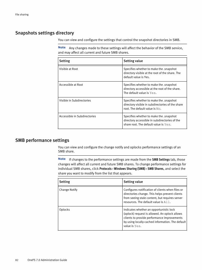
Snapshots settings directoryYou can view and configure the settings that control the snapshot directories in SMB.
Any changes made to these settings will affect the behavior of the SMB service,and may affect all current and future SMB shares.
Setting Setting value- -Visible at Root Specifies whether to make the .snapshot
directory visible at the root of the share. Thedefault value is Yes.
Accessible at Root Specifies whether to make the .snapshotdirectory accessible at the root of the share.The default value is Yes.
Visible in Subdirectories Specifies whether to make the .snapshotdirectory visible in subdirectories of the shareroot. The default value is No.
Accessible in Subdirectories Specifies whether to make the .snapshotdirectory accessible in subdirectories of theshare root. The default value is Yes.
SMB performance settingsYou can view and configure the change notify and oplocks performance settings of anSMB share.
If changes to the performance settings are made from the SMB Settings tab, thosechanges will affect all current and future SMB shares. To change performance settings forindividual SMB shares, click Protocols > Windows Sharing (SMB) > SMB Shares, and select theshare you want to modify from the list that appears.
Setting Setting value- -Change Notify Configures notification of clients when files or
directories change. This helps prevent clientsfrom seeing stale content, but requires serverresources. The default value is All.
Oplocks Indicates whether an opportunistic lock(oplock) request is allowed. An oplock allowsclients to provide performance improvementsby using locally-cached information. The defaultvalue is Yes.
File sharing
82 OneFS 7.0 Administration Guide

SMB security settingsYou can view and configure the Impersonate Guest, Impersonate User, and NTFS ACLsecurity settings of an SMB share.
If changes to the security settings are made from the SMB Settings tab, thosechanges will affect all current and future SMB shares. To change settings for individualSMB shares, click Protocols > Windows Sharing (SMB) > SMB Shares, and select the share youwant to modify from the list that appears.
Setting Setting value- -Impersonate Guest Determines guest access to a share. The default
value is Never.
Impersonate User Allows all file access to be performed as aspecific user. This must be a fully qualified username. The default value is No value.
NTFS ACL Allows ACLs to be stored and edited from SMBclients. The default value is Yes.
Configure and enable HTTP file sharingYou can configure HTTP and DAV to enable users to edit and manage files collaborativelyacross remote web servers.
1. Navigate to Protocols > HTTP Settings.
2. Select the setting for HTTP Protocol:l Enable HTTP. Allows HTTP access for cluster administration and browsing content
on the cluster.
l Disable HTTP and redirect to the web interface. Allows only administrative access tothe web administration interface. This is the default mode.
l Disable HTTP entirely. Closes the HTTP port used for file access. Users can stillaccess the web administration interface, but they must specify the port number(8080) in the URL in order to do so.
3. In the Document root directory field, type or click Browse to navigate to an existingdirectory in /ifs, or click File System Explorer to create a new directory and set itspermissions.
The HTTP server runs as the daemon user and group. To properly enforceaccess controls, you must grant the daemon user or group read access to all filesunder the document root, and allow the HTTP server to traverse the document root.
4. In the Server hostname field, type the HTTP server name. The server hostname must bea fully-qualified, SmartConnect zone name and valid DNS name. The name mustbegin with a letter and contain only letters, numbers, and hyphens (-).
5. In the Administrator email address field, type an email address to display as the primarycontact for issues that occur while serving files.
6. From the Active Directory Authentication list, select an authentication setting:l Off.
File sharing
SMB security settings 83
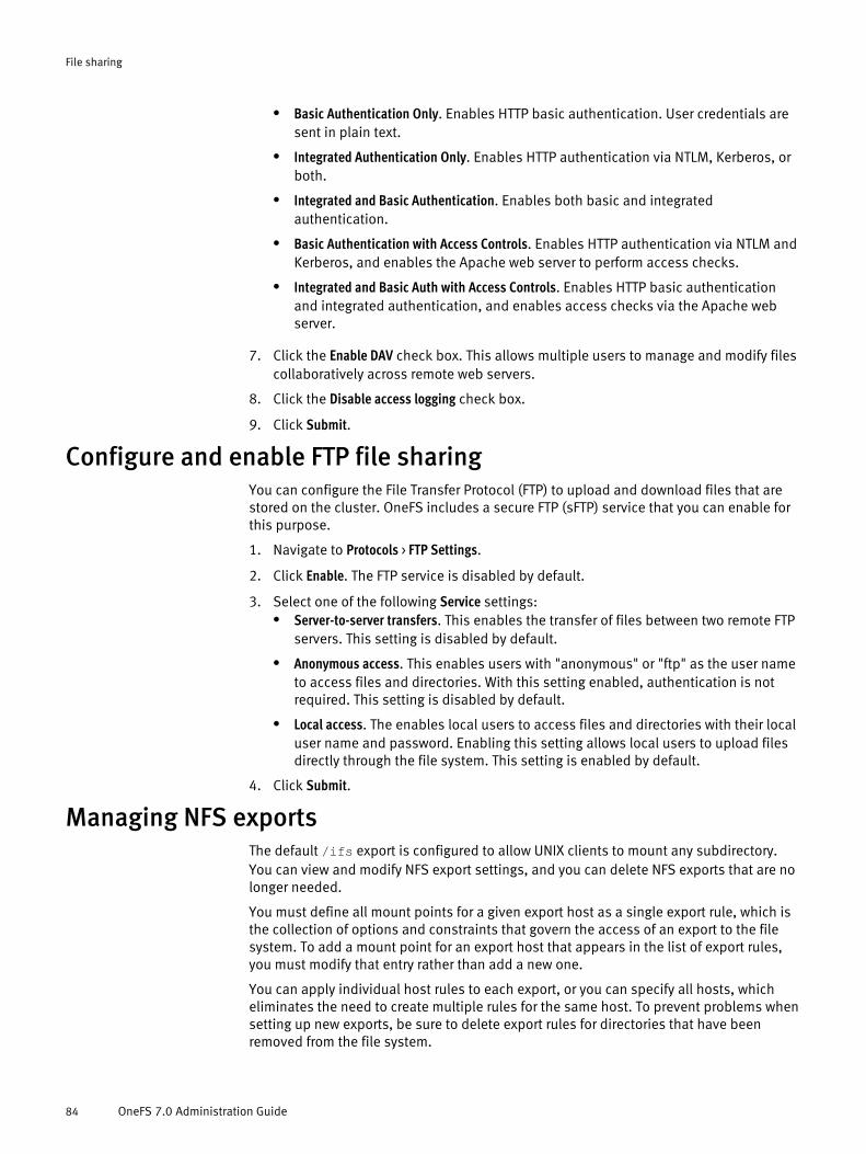
l Basic Authentication Only. Enables HTTP basic authentication. User credentials aresent in plain text.
l Integrated Authentication Only. Enables HTTP authentication via NTLM, Kerberos, orboth.
l Integrated and Basic Authentication. Enables both basic and integratedauthentication.
l Basic Authentication with Access Controls. Enables HTTP authentication via NTLM andKerberos, and enables the Apache web server to perform access checks.
l Integrated and Basic Auth with Access Controls. Enables HTTP basic authenticationand integrated authentication, and enables access checks via the Apache webserver.
7. Click the Enable DAV check box. This allows multiple users to manage and modify filescollaboratively across remote web servers.
8. Click the Disable access logging check box.
9. Click Submit.
Configure and enable FTP file sharingYou can configure the File Transfer Protocol (FTP) to upload and download files that arestored on the cluster. OneFS includes a secure FTP (sFTP) service that you can enable forthis purpose.
1. Navigate to Protocols > FTP Settings.
2. Click Enable. The FTP service is disabled by default.
3. Select one of the following Service settings:l Server-to-server transfers. This enables the transfer of files between two remote FTP
servers. This setting is disabled by default.
l Anonymous access. This enables users with "anonymous" or "ftp" as the user nameto access files and directories. With this setting enabled, authentication is notrequired. This setting is disabled by default.
l Local access. The enables local users to access files and directories with their localuser name and password. Enabling this setting allows local users to upload filesdirectly through the file system. This setting is enabled by default.
4. Click Submit.
Managing NFS exportsThe default /ifs export is configured to allow UNIX clients to mount any subdirectory.You can view and modify NFS export settings, and you can delete NFS exports that are nolonger needed.
You must define all mount points for a given export host as a single export rule, which isthe collection of options and constraints that govern the access of an export to the filesystem. To add a mount point for an export host that appears in the list of export rules,you must modify that entry rather than add a new one.
You can apply individual host rules to each export, or you can specify all hosts, whicheliminates the need to create multiple rules for the same host. To prevent problems whensetting up new exports, be sure to delete export rules for directories that have beenremoved from the file system.
File sharing
84 OneFS 7.0 Administration Guide

Changes to the advanced settings affect all current and future NFS exports thatuse default settings, and may impact the availability of the NFS file sharing service. Donot make changes to these settings unless you have experience working with NFS. It isrecommended that you change the default values for individual NFS exports as you createthem, or edit the settings of existing exports.
Modify an NFS exportYou can modify the settings for individual NFS exports.
1. ClickProtocols > UNIX Sharing (NFS) > NFS Export.
2. From the list of NFS exports, click View details for the export whose settings you wantto modify.
3. For each setting that you want to modify, click Edit, make the change, and then clickSave.
4. Click Close.
Delete an NFS exportYou can delete NFS exports that are no longer needed.
You can delete all the exports on a cluster by selecting the Export ID/Path option,and then selecting Delete from the drop-down menu.
1. Click Protocols > UNIX Sharing (NFS) > NFS Export
2. From the list of NFS exports, click the check box for the export that you want to delete.
3. Click Delete.
4. In the confirmation dialog box, click Delete to confirm the deletion.
View and configure default NFS export settingsDefault settings apply to all current and future NFS exports. For each setting, you cancustomize the default value or select the factory default value. The factory default valuecannot be modified.
Modifying the global default values is not recommended. You can override thesettings for NFS exports as you create them, or modify the settings for existing exports.
1. Click Protocols > UNIX Sharing (NFS) > NFS Settings.
2. Click the NFS export settings menu.
3. For each setting that you want to modify, click System Default in the list of options andselect Custom Default.
If a confirmation dialog box appears, click Continue.
4. Make your changes to the information in the setting value text field.
5. When you are finished modifying settings, click Save.
File sharing
Modify an NFS export 85
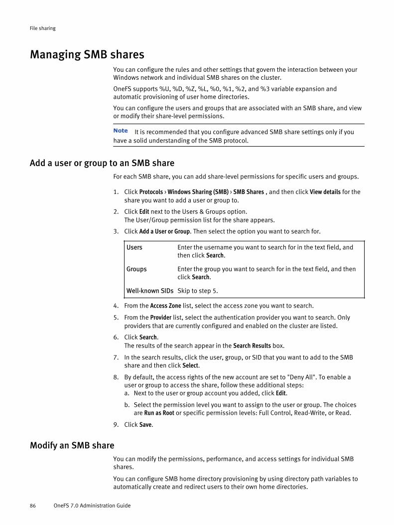
Managing SMB sharesYou can configure the rules and other settings that govern the interaction between yourWindows network and individual SMB shares on the cluster.
OneFS supports %U, %D, %Z, %L, %0, %1, %2, and %3 variable expansion andautomatic provisioning of user home directories.
You can configure the users and groups that are associated with an SMB share, and viewor modify their share-level permissions.
It is recommended that you configure advanced SMB share settings only if youhave a solid understanding of the SMB protocol.
Add a user or group to an SMB shareFor each SMB share, you can add share-level permissions for specific users and groups.
1. Click Protocols > Windows Sharing (SMB) > SMB Shares , and then click View details for theshare you want to add a user or group to.
2. Click Edit next to the Users & Groups option.The User/Group permission list for the share appears.
3. Click Add a User or Group. Then select the option you want to search for.
Users Enter the username you want to search for in the text field, andthen click Search.
Groups Enter the group you want to search for in the text field, and thenclick Search.
Well-known SIDs Skip to step 5.
4. From the Access Zone list, select the access zone you want to search.
5. From the Provider list, select the authentication provider you want to search. Onlyproviders that are currently configured and enabled on the cluster are listed.
6. Click Search.The results of the search appear in the Search Results box.
7. In the search results, click the user, group, or SID that you want to add to the SMBshare and then click Select.
8. By default, the access rights of the new account are set to "Deny All". To enable auser or group to access the share, follow these additional steps:a. Next to the user or group account you added, click Edit.
b. Select the permission level you want to assign to the user or group. The choicesare Run as Root or specific permission levels: Full Control, Read-Write, or Read.
9. Click Save.
Modify an SMB shareYou can modify the permissions, performance, and access settings for individual SMBshares.
You can configure SMB home directory provisioning by using directory path variables toautomatically create and redirect users to their own home directories.
File sharing
86 OneFS 7.0 Administration Guide

Any changes made to these settings will only affect the settings for this share. Ifyou need to make changes to the global default values, that can be done from the SMBSettings tab.
1. Click Protocols > Windows Sharing (SMB) > SMB Shares.
2. From the list of SMB shares, locate the share you want to modify and then click Viewdetails.
3. For each setting that you want to modify, click Edit, make the change, and then clickSave.
4. To modify the settings for file and directory permissions, performance, or security,click Advanced SMB Share Settings.
Delete an SMB shareYou can delete SMB shares that are no longer needed.
While unused SMB shares do not hinder cluster performance, they can be deleted. Whenan SMB share is deleted, the path of the share is deleted but the directory it referencedwill still exist. If you create a new share with the same path as the share that was deleted,the directory the previous share referenced will be accessible again through the newshare.
You can delete all of the shares on a cluster by selecting the Name/Path option,and then selecting Delete from the drop-down menu.
1. On the web dashboard, click Protocols > Windows Sharing (SMB) > SMB Shares .
2. Select the share you want to delete from the list of SMB shares listed.
3. Click Delete.
4. In the confirmation dialog box, click Delete to confirm the deletion.
SMB share settingsSettings for SMB shares can be applied on individual shares, or on a global level for theentire SMB service.
SMB share settingsThe settings for an SMB share can be applied at the time the share is created, or modifiedat a later time. To view the settings for an individual SMB share, on the web dashboardclick Protocols > Windows Sharing (SMB) > SMB Shares. A list of SMB shares will appear.Locate the share you want to view the settings for, then click the View details link.
The basic settings for an SMB share are the following:
u Share Name.
u Description.
u Shared Directory.
u Home Directory Provisioning.
u Users and Groups.
The advanced settings for individual SMB shares are the same as the advanced settingsfor all SMB shares. If you need to change the global default values for the advancedsettings, click the SMB Settings tab.
File sharing
Delete an SMB share 87

Uninformed changes to the advanced settings could result in operational failures.Be aware of the potential consequences of changes before committing to save them.
The advanced settings for an SMB share are the following:
u File and Directory Permissions.
The File and Directory Permissions include Create Permissions, Create Mask (Dir), CreateMode (Dir), Create Mask (File), and Create Mode (File).
u Performance settings.
The Performance settings include Change Notify and Oplocks.
The Security settings include Impersonate Guest, Impersonate User, and NTFS ACL.
u Security Settings.
The Security settings include Impersonate Guest, Impersonate User, and NTFS ACL.
View and modify SMB share settingsYou can view the status and settings of any SMB shares on the cluster.
1. Click Protocols > Windows Sharing (SMB) > SMB Shares .
2. To view the settings for file and directory permissions, performance, or security, clickAdvanced SMB Share Settings.
Any changes made to these settings will override the default settings for thisshare only. If you need to make changes to the global default values, that can bedone from the SMB Settings tab.
File sharing
88 OneFS 7.0 Administration Guide

CHAPTER 4
Snapshots
A OneFS snapshot is a logical pointer to data stored on a cluster at a specific point intime. A snapshot contains a directory on a cluster, and includes all data stored in thegiven directory and any subdirectories that the directory contains. If data contained in asnapshot is modified, the snapshot stores a physical copy of the original data, andreferences the copy.
Snapshots are created according to users' specifications, or automatically generated byOneFS to facilitate system operations. In some cases, snapshots generated by OneFSoperations are optional and can be disabled. However, some applications are unable tofunction without generating snapshots.
To create and manage snapshots, you must configure a SnapshotIQ license on thecluster. However, some OneFS operations generate snapshots without requiring that theSnapshotIQ license be configured. If an application generates a snapshot, and aSnapshotIQ license is not configured, you can still view the snapshot. However, there aresome OneFS operations that generate snapshots for internal system use. Unless aSnapshotIQ license is configured, all snapshots generated by OneFS operations areautomatically deleted after they are no longer needed.
You can identify and locate snapshots by the snapshot name or ID. A snapshot name isspecified by a user and assigned to the subdirectory that contains the snapshot. Asnapshot ID is a numerical identifier that is assigned to snapshots by the system.
u Data protection with SnapshotIQ...........................................................................90u Snapshot disk-space usage...................................................................................90u Snapshot schedules..............................................................................................91u Snapshot aliases...................................................................................................91u File and directory restoration.................................................................................91u File clones.............................................................................................................91u Snapshot locks.....................................................................................................93u Snapshot reserve..................................................................................................93u SnapshotIQ license functionality...........................................................................93u Creating snapshots with SnapshotIQ.....................................................................94u Managing snapshots ............................................................................................99u Restoring snapshot data.....................................................................................102u Managing snapshot schedules............................................................................103u Managing with snapshot locks............................................................................104u Configure SnapshotIQ settings............................................................................106u Set the snapshot reserve.....................................................................................107
Snapshots 89

Data protection with SnapshotIQYou can create snapshots to protect data through the SnapshotIQ tool. Snapshots protectdata against accidental deletion and modification by enabling you to restore deleted filesand revert modified files. To use the SnapshotIQ tool, you must configure a SnapshotIQlicense on the cluster.
Snapshots are less costly than backing up your data on a separate physical storagedevice in terms of both time and storage consumption. While the time required to movedata to another physical device depends on the amount of data being moved, snapshotsare created almost instantaneously regardless of the amount of data contained in thesnapshot. Also, because snapshots are available locally, end-users can often restoretheir data without the assistance of a system administrator, saving administrators thetime it takes to retrieve the data from another physical location.
Snapshots require less space than a remote backup because unaltered data isreferenced rather than recreated. Using another physical storage device requires you tocreate another physical copy of the data.
It is important to remember that snapshots do not protect against hardware or file-systemissues. Snapshots reference data that is stored on a cluster, and if the data on a clusterbecomes unavailable, the snapshots will also be unavailable. Because of this, it isrecommended that you use snapshots in addition to backing up your data on a separatephysical device. Snapshots are convenient, but do not protect against all forms of dataloss.
Snapshot disk-space usageThe amount of disk space used by a snapshot is dependent on the number of snapshotsthat contain the data and the amount of modifications made to the data that thesnapshot contains.
At the time it is created, a OneFS snapshot consumes a negligible amount of storagespace on the cluster. However, as the files that a snapshot contains are modified, thesnapshot stores read-only copies of the unmodified data. This allows the snapshot tomaintain a pointer to data that existed in a directory at the time that the snapshot wascreated, even after the data has changed. A snapshot consumes only the space that isnecessary to restore the data contained in the snapshot. If the data that a snapshotcontains is not modified, the snapshot does not consume additional storage space onthe cluster.
In order to reduce storage disk-space usage, snapshots that contain the sameinformation reference each other, with older snapshots referencing newer ones. If data ismodified on the cluster, and several snapshots contain the same data, only one copy ofthe unmodified data is made. The size of a snapshot reflects the amount of disk-spaceconsumed by physical copies of data stored in that snapshot. However, snapshotsalmost always reference data that is stored by other snapshots. The size of a snapshotdoes not reflect the amount of data that is referenced by that snapshot.
Because OneFS snapshots do not consume a set amount of storage space, there is noavailable-space requirement for creating a snapshot. The size of a snapshot growsaccording to the modification of the data that it contains. However, a cluster can containno more than 2048 snapshots.
Snapshots
90 OneFS 7.0 Administration Guide

Snapshot schedulesOneFS can automatically generate snapshots intermittently according to a snapshotschedule.
With snapshot schedules, you can periodically generate snapshots of a directory, withouthaving to manually create a snapshot every time. You can also assign an expirationperiod to the snapshots that are generated, causing OneFS to automatically delete eachsnapshot after the specified period has expired. It is often advantageous to create morethan one snapshot per directory, with shorter duration periods assigned to snapshotsthat are generated more frequently, and longer expiration periods assigned to snapshotsthat are generated less frequently.
Snapshot aliasesA snapshot alias is an optional, alternative name for a snapshot. If a snapshot isassigned an alias, and that alias is later assigned to another snapshot, the alias isautomatically removed from the old snapshot before it is assigned to the new snapshot.
Snapshot aliases are most commonly used by snapshot schedules. When specified in asnapshot schedule, OneFS assigns the alias to each snapshot generated by theschedule. The alias is then attached only to the most recent snapshot generated basedon the schedule. You can use aliases to quicky identify the most recent snapshotgenerated according to a schedule.
OneFS also uses snapshot aliases internally to identify the most recent snapshotgenerated by OneFS operations.
File and directory restorationThere are various ways that you can restore the files and directories contained insnapshots. You can copy data from a snapshot, clone a file from a snapshot, or revert anentire snapshot.
Copying a file out of a snapshot creates a new copy of the file on the cluster. If you copy afile from a snapshot, two copies of the same file exist on the cluster, taking up twice theamount of storage space as the original file. Even if you delete the original file from thenon-snapshot directory, the copy of the file is still stored in the snapshot.
You can also clone a file from a snapshot. While copying a file from a snapshotimmediately consumes additional space on the cluster, cloning a file from a snapshotdoes not consume any additional space on the cluster unless the clone or cloned file ismodified.
You can also revert an entire snapshot. Reverting a snapshot replaces the contents of adirectory with the data stored in a snapshot. Before a snapshot is reverted, OneFS createsa snapshot of the directory that is being replaced, enabling you to undo a snapshotrevert. Reverting a snapshot can be useful if you have made many changes to files anddirectories contained in a snapshot and you want to revert all of the changes. If new filesor directories have been created in a directory since a snapshot of the directory wascreated, those files and directories are deleted when the snapshot is reverted.
File clonesOneFS enables you to create file clones that share blocks with existing files in order tosave space on the cluster. Although you can clone files from snapshots, clones areprimarily used internally by OneFS.
File clones share blocks with existing files in order to save space on the cluster. Theshared blocks are contained in a shadow store that is referenced by both the clone and
Snapshots
Snapshot schedules 91

the cloned file. A file clone usually consumes less space and takes less time to createthan a file copy.
Immediately after a clone is created, all data originally contained in the cloned file istransferred to a shadow store. A shadow store is a hidden file that is used to hold shareddata for clones and cloned files. Because both files reference all blocks from the shadowstore, the two files consume no more space than the original file; the clone does not takeup any additional space on the cluster. However, if the cloned file or clone is modified,the file and clone will share only blocks that are common to both of them, and themodified, unshared blocks will occupy additional space on the cluster.
Over time, the shared blocks contained in the shadow store might become useless ifneither the file nor clone references the blocks. The blocks that are no longer needed aredeleted routinely by the cluster. However, you can cause the cluster to delete unusedblocks at any time by running the shadow store delete job.
File clones considerationsClones of files and cloned files behave differently in OneFS than files that have not beencloned.
Be aware of the following considerations about file clones:
u Reading a cloned file might be slower than reading a copied file. Specifically, readingnon-cached data from a cloned file is slower than reading non-cached data from acopied file. Reading cached data from a cloned file takes no more time than readingcached data from a copied file.
u When a file and its clone are replicated to another Isilon cluster or backed up to anNetwork Data Management Protocol (NDMP) backup device, the file and clone do notshare blocks on the target Isilon cluster or backup device. Shadows stores are nottransferred to the target cluster or backup device, so clones and cloned files consumethe same amount of space as copies.
u When a file is cloned, the shadow store referenced by the clone and cloned file isassigned to the storage pool of the cloned file. If you delete the storage pool that theshadow store resides on, the shadow store is moved to a pool occupied either by theoriginal file or a clone of the file.
u The protection level of a shadow store is at least as high as the most protected file orclone associated referencing the shadow store. For example, if a cloned file resides ina storage pool with +2 protection, and the clone resides in a storage pool with +3protection, the shadow store is protected at +3.
u Quotas account for clones and cloned files as if they consumed both shared andunshared data; from the perspective of a quota, a clone and a copy of the same filedo not consume different amounts of data. However, if the quota includes dataprotection overhead, the data protection overhead for the shadow store is notaccounted for by the quota.
u Clones cannot contain alternate data streams. If you clone a file with alternate datastreams (ADS), the clone will not contain the alternate data streams.
Snapshots
92 OneFS 7.0 Administration Guide

iSCSI LUN clonesOneFS enables you to create clones of iSCSI logical units (LUNs) that share blocks withexisting LUNs in order to save space on the cluster. Internally, OneFS creates iSCSI LUNclones by creating file clones.
Snapshot locksA snapshot lock prevents a snapshot from being deleted. If a snapshot has one or morelocks applied to it, the snapshot cannot be deleted and is referred to as a lockedsnapshot.
You cannot delete a locked snapshot manually. OneFS is also unable to delete asnapshot lock. If the duration period of a locked snapshot expires, the snapshot will notbe deleted by the system until all locks on the snapshot have been deleted.
OneFS applies snapshot locks to ensure that snapshots generated by OneFS applicationsare not deleted prematurely. For this reason, it is recommended that you do not deletesnapshot locks or modify the duration period of snapshot locks.
A limited number of locks can be applied to a snapshot at a time. If you create too manysnapshot locks and the limit is reached, OneFS might be unable to apply a snapshot lockwhen necessary. For this reason, it is recommended that you do not create snapshotlocks.
Snapshot reserveThe snapshot reserve enables you to set aside a minimum portion of the cluster-storagecapacity specifically for snapshots. If specified, the percentage of cluster capacity that isreserved for snapshots is not accessible to any other OneFS operation.
The snapshot reserve does not limit the amount of space that snapshots areallowed to consume on the cluster. Snapshots can consume more than the percentage ofcapacity specified by the snapshot reserve. It is recommended that you do not specify asnapshot reserve.
SnapshotIQ license functionalityYou can create snapshots only if you configure a SnapshotIQ license on a cluster.However, you can view snapshots and snapshot locks that are created for internal use byOneFS without configuring a SnapshotIQ license.
The following table describes the functionality that is available with the SnapshotIQlicense in both configured and unconfigured states:
Configured Unconfigured- - -Create snapshots andsnapshot schedules
Yes No
Configure SnapshotIQ settings Yes No
View snapshot schedules Yes Yes
Delete snapshots Yes Yes
Access snapshot data Yes Yes
Snapshots
iSCSI LUN clones 93
Configured Unconfigured- - -View snapshots Yes Yes
If you unconfigure a SnapshotIQ license, you will not be able to create new snapshots, allsnapshot schedules will be disabled, and you will not be able to modify snapshots orsnapshot settings. However, you will still be able to delete snapshots and access datacontained in snapshots.
Creating snapshots with SnapshotIQTo create snapshots, you must configure the SnapshotIQ licence on the cluster. You cancreate snapshots either by creating a snapshot schedule or manually generating anindividual snapshot.
Manual snapshots are useful if you want to create a snapshot immediately, or at a timethat is not specified in a snapshot schedule. For example, if you plan to make changes toyour file system, but are unsure of the consequences, you can capture the current state ofthe file system in a snapshot before you make the change.
Before capturing snapshots, consider that reverting a snapshot requires that aSnapRevert domain exist for the directory that is being reverted. If you intend on revertingsnapshots for a directory, it is recommended that you create SnapRevert domains forthose directories while the directories are empty.
Create a SnapRevert domainBefore you can revert a snapshot that contains a directory, you must create a SnapRevertdomain for the directory. It is recommended that you create SnapRevert domains for adirectory while the directory is empty.
The root path of the SnapRevert domain must be the same root path of the snapshot. Forexample, a domain with a root path of /ifs/data/media cannot be used to revert asnapshot with a root path of /ifs/data/media/archive. To revert /ifs/data/media/archive, you must create a SnapRevert domain with a root path of /ifs/data/media/archive.
1. Click Cluster Management > Operations > Operations Summary.
2. In the Running Jobs area, click Start Job.
3. From the Job list, select Domain Mark.
4. Optional: To specify the priority a priority for the job, from the Priority list, select apriority.
Lower values indicate a higher priority. If you do not specify a priority, the job isassigned the default domain mark priority.
5. Optional: To specify the amount of cluster resources the job is allowed to consume,from the Impact policy list, select an impact policy.
If you do not specify a policy, the job is assigned the default domain mark policy.
6. From the Domain type list, select snaprevert.
7. Ensure that the Delete domain check box is cleared.
8. In the Domain root path field, type the path of the directory you want to create aSnapRevert domain for, and then click Start.
Snapshots
94 OneFS 7.0 Administration Guide
Create a snapshotYou can create a snapshot of a directory.
1. Click Data Protection > SnapshotIQ > Summary.
2. Click Capture a new snapshot.
3. Optional: To modify the default name of a snapshot, in the Capture a Snapshot area, inthe Snapshot Name field, type a name
4. In the Directory Path field, specify the directory that you want the snapshot to contain.
5. Optional: To create an alternative name for the snapshot, specify a snapshot alias.a. Next to Create an Alias, click Yes.
b. To modify the default snapshot alias name, in the Alias Name field, type analternative name for the snapshot.
6. Optional: To assign a time that OneFS will automatically delete the snapshot, specifyan expiration period.a. Next to Snapshot Expiration, click Snapshot Expires on.
b. In the calendar, specify the day that you want the snapshot to be automaticallydeleted.
7. Click Capture.
Create a snapshot scheduleYou can create a snapshot schedule to continuously generate snapshots of directories.
1. Click Data Protection > SnapshotIQ > Snapshot Schedules.
2. Click Create a snapshot schedule.
3. Optional: To modify the default name of the snapshot schedule, in the Create aSnapshot Schedule area, in the Schedule Name field, type a name for the snapshotschedule.
4. Optional: To modify the default naming pattern for the snapshot schedule, in theNaming pattern for Generated Snapshots field, type a naming pattern. Each snapshotgenerated according to this schedule is assigned a name based on the pattern.For example, the following naming pattern is valid:
WeeklyBackup_%m-%d-%Y_%H:%M
The example produces names similar to the following:
WeeklyBackup_07-13-2012_14:215. In the Directory Path field, specify the directory that you want to be contained in
snapshots that are generated according to this schedule.
6. Specify how often you want to generate snapshots according to the schedule.
Generate snapshots every day, or skipgenerating snapshots for a specifiednumber of days.
From the Snapshot Frequency list, selectDaily, and specify how often you want togenerate snapshots.
Generate snapshots on specific days ofthe week, and optionally skipgenerating snapshots for a specifiednumber of weeks.
From the Snapshot Frequency list, selectWeekly and specify how often you want togenerate snapshots.
Snapshots
Create a snapshot 95

Generate snapshots on specific days ofthe month, and optionally skipgenerating snapshots for a specifiednumber of months.
From the Snapshot Frequency list, selectMonthly and specify how often you want togenerate snapshots.
Generate snapshots on specific days ofthe year.
From the Snapshot Frequency list, selectYearly and specify how often you want togenerate snapshots.
A snapshot schedule cannot span multiple days. For example, you cannotspecify to begin generating snapshots at 5:00 PM Monday and end at 5:00 AMTuesday. To continuously generate snapshots for a period greater than a day, youmust create two snapshot schedules. For example, to generate snapshots from 5:00PM Monday to 5:00 AM Tuesday, create one schedule that generates snapshots from5:00 PM to 11:59 PM on Monday, and another schedule that generates snapshotsfrom 12:00 AM to 5:00 AM on Tuesday.
7. Optional: To assign an alternative name to the most recent snapshot generated bythe schedule, specify a snapshot alias.a. Next to Create an Alias, click Yes.
b. To modify the default snapshot alias name, in the Alias Name field, type analternative name for this snapshot.
8. Optional: To specify a length of time that snapshots generated according to theschedule exist on the cluster before they are automatically deleted by OneFS, specifyan expiration period.a. Next to Snapshot Expiration, click Snapshots expire.
b. Next to Snapshots expire, specify how long you want to retain the snapshotsgenerated according to this schedule.
9. Click Create.
Snapshot naming patternsIf you schedule snapshots to be automatically generated by OneFS, either according to asnapshot schedule or a replication policy, you must assign a snapshot naming patternthat determines how the snapshots are named. Snapshot naming patterns containvariables that include information about how and when the snapshot is created.
The following variables can be included in a snapshot naming pattern:
Variable Description- -%A The day of the week.
%a The abbreviated day of the week. For example,if the snapshot is generated on a Sunday, %a isreplaced with "Sun".
%B The name of the month.
%b The abbreviated name of the month. Forexample, if the snapshot is generated inSeptember, %b is replaced with "Sep".
Snapshots
96 OneFS 7.0 Administration Guide

Variable Description- -%C The first two digits of the year. For example, if
the snapshot is created in 2012, %C is replacedwith "20".
%c The time and day. This variable is equivalent tospecifying "%a %b %e %T %Y".
%d The two digit day of the month.
%e The day of the month. A single-digit day ispreceded by a blank space.
%F The date. This variable is equivalent tospecifying "%Y-%m-%d"
%G The year. This variable is equivalent tospecifying "%Y". However, if the snapshot is
created in a week that has less than four daysin the current year, the year that contains themajority of the days of the week is displayed.The first day of the week is calculated asMonday. For example, if a snapshot is createdon Sunday, January 1, 2017, %G is replacedwith "2016", because only one day of that
week is in 2017.
%g The abbreviated year. This variable isequivalent to specifying "%y". However, if the
snapshot was created in a week that has lessthan four days in the current year, the year thatcontains the majority of the days of the week isdisplayed. The first day of the week iscalculated as Monday. For example, if asnapshot is created on Sunday, January 1,2017, %g is replaced with "16", because only
one day of that week is in 2017.
%H The hour. The hour is represented on the 24-hour clock. Single-digit hours are preceded by azero. For example, if a snapshot is created at1:45 AM, %H is replaced with "01".
%h The abbreviated name of the month. Thisvariable is equivalent to specifying "%b".
%I The hour represented on the 12-hour clock.Single-digit hours are preceded by a zero. Forexample, if a snapshot is created at 1:45 AM,%I is replaced with "01".
%j The numeric day of the year. For example, if asnapshot is created on February 1, %j isreplaced with "32".
Snapshots
Snapshot naming patterns 97

Variable Description- -%k The hour represented on the 24-hour clock.
Single-digit hours are preceded by a blankspace.
%l The hour represented on the 12-hour clock.Single-digit hours are preceded by a blankspace. For example, if a snapshot is created at1:45 AM, %I is replaced with "1".
%M The two-digit minute.
%m The two-digit month.
%p AM or PM.
%{PolicyName} The name of the replication policy that thesnapshot was created for. This variable is validonly if you are specifying a snapshot namingpattern for a replication policy.
%R The time. This variable is equivalent tospecifying "%H:%M".
%r The time. This variable is equivalent tospecifying "%I:%M:%S %p".
%S The two-digit second.
%s The second represented in UNIX or POSIX time.
%{SrcCluster} The name of the source cluster of thereplication policy that the snapshot wascreated for. This variable is valid only if you arespecifying a snapshot naming pattern for areplication policy.
%T The time. This variable is equivalent tospecifying "%H:%M:%S"
%U The two-digit numerical week of the year.Numbers range from 00 to 53. The first day of
the week is calculated as Sunday.
%u The numerical day of the week. Numbers rangefrom 1 to 7. The first day of the week is
calculated as Monday. For example, if asnapshot is created on Sunday, %u is replacedwith "7".
%V The two-digit numerical week of the year thatthe snapshot was created in. Numbers rangefrom 01 to 53. The first day of the week is
calculated as Monday. If the week of January 1is four or more days in length, then that week iscounted as the first week of the year.
Snapshots
98 OneFS 7.0 Administration Guide
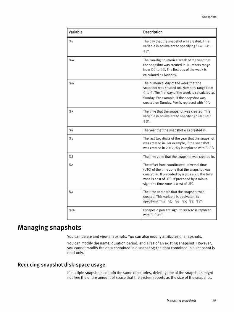
Variable Description- -%v The day that the snapshot was created. This
variable is equivalent to specifying "%e-%b-%Y".
%W The two-digit numerical week of the year thatthe snapshot was created in. Numbers rangefrom 00 to 53. The first day of the week is
calculated as Monday.
%w The numerical day of the week that thesnapshot was created on. Numbers range from0 to 6. The first day of the week is calculated as
Sunday. For example, if the snapshot wascreated on Sunday, %w is replaced with "0".
%X The time that the snapshot was created. Thisvariable is equivalent to specifying "%H:%M:%S".
%Y The year that the snapshot was created in.
%y The last two digits of the year that the snapshotwas created in. For example, if the snapshotwas created in 2012, %y is replaced with "12".
%Z The time zone that the snapshot was created in.
%z The offset from coordinated universal time(UTC) of the time zone that the snapshot wascreated in. If preceded by a plus sign, the timezone is east of UTC. If preceded by a minussign, the time zone is west of UTC.
%+ The time and date that the snapshot wascreated. This variable is equivalent tospecifying "%a %b %e %X %Z %Y".
%% Escapes a percent sign. "100%%" is replacedwith "100%".
Managing snapshotsYou can delete and view snapshots. You can also modify attributes of snapshots.
You can modify the name, duration period, and alias of an existing snapshot. However,you cannot modify the data contained in a snapshot; the data contained in a snapshot isread-only.
Reducing snapshot disk-space usageIf multiple snapshots contain the same directories, deleting one of the snapshots mightnot free the entire amount of space that the system reports as the size of the snapshot.
Snapshots
Managing snapshots 99

The size of a snapshot is the maximum amount of data that might be freed if thesnapshot is deleted.
Be aware of the following considerations when attempting to reduce the capacity used bysnapshots:
u Deleting a snapshot frees only the space that is taken up exclusively by thatsnapshot. If two snapshots reference the same stored data, that data is not freeduntil both snapshots are deleted. Remember that snapshots store data contained inall subdirectories of the root directory; if snapshot_one contains /ifs/data/, andsnapshot_two contains /ifs/data/dir, the two snapshots most likely share data.
u If you delete a directory, and then re-create it, a snapshot containing the directorystores the entire re-created directory, even if the files in that directory are nevermodified.
u Deleting multiple snapshots that contain the same directories is more likely to freedata than deleting multiple snapshots that contain different directories.
u If multiple snapshots of the same directories exist, deleting the older snapshots ismore likely to free disk-space than deleting newer snapshots. Snapshots store onlydata that cannot be found on the file system or another snapshot.If you delete the oldest snapshot of a directory, the amount of space known as thesize of the snapshot will be freed.
u Snapshots that are assigned expiration dates are automatically marked for deletionby the snapshot daemon. If the daemon is disabled, snapshots will not beautomatically deleted by the system.
Delete snapshotsYou can delete a snapshot if you no longer want to access the data contained in thesnapshot.
Disk space occupied by deleted snapshots is freed when the snapshot delete job is run.Also, if you delete a snapshot that contains clones or cloned files, data in a shadow storemight no longer be referenced by files on the cluster; unreferenced data in a shadowstore is deleted when the shadow store delete job is run. OneFS routinely runs both theshadow store delete and snapshot delete jobs. However, you can also manually run thejobs at any time.
1. Click Data Protection > SnapshotIQ > Snapshots.
2. Specify the snapshots that you want to delete.a. For each snapshot you want to delete, in the Saved File System Snapshots table, in
the row of a snapshot, select the check box.
b. From the Select an action list, select Delete.
c. In the confirmation dialog box, click Delete.
3. Optional: To increase the speed at which deleted snapshot data is freed on thecluster, run the snapshot delete job.a. Navigate to Cluster Management > Operations.
b. In the Running Jobs area, click Start Job.
c. From the Job list, select SnapshotDelete.
d. Click Start.
4. Optional: To increase the speed at which deleted data shared between cloned files isfreed on the cluster, run the shadow store delete job.
Run the shadow store delete job only after you run the snapshot delete job.
Snapshots
100 OneFS 7.0 Administration Guide

a. Navigate to Cluster Management > Operations.
b. In the Running Jobs area, click Start Job.
c. From the Job list, select ShadowStoreDelete.
d. Click Start.
Modify a snapshotYou can modify the name and expiration date of a snapshot.
1. Click File System Management > SnapshotIQ > Snapshots.
2. In the Saved File System Snapshots table, in the row of the snapshot that you want tomodify, click View Details.
3. In the Snapshot Details area, modify snapshot attributes.
4. Next to each snapshot attribute that you modified, click Save.
Modify a snapshot aliasYou can modify the alias of a snapshot to assign a different alternative name for thesnapshot.
1. Click Data Protection > SnapshotIQ > Snapshots.
2. Above the Saved File System Snapshots table, click View snapshot aliases.
3. In the Snapshot Aliases table, in the row of the alias that you want to modify, click Viewdetails.
4. In the Snapshot Alias Details pane, in the Alias Name area, click Edit.
5. In the Alias Name field, type a new alias name.
6. Click Save.
View snapshotsYou can view all snapshots.
1. Click Data Protection > SnapshotIQ > Snapshots.
2. In the Saved File System Snapshots table, view snapshots.
Snapshot informationYou can view information about snapshots, including the total amount of spaceconsumed by all snapshots.
The following information is displayed in the Saved Snapshots area:
u SnapshotIQ Status — Indicates whether the SnapshotIQ tool is accessible on the cluster.
u Total Number of Saved Snapshots — Indicates the total number of snapshots thatexist on the cluster.
u Total Number of Snapshots Pending Deletion — Indicates the total number ofsnapshots that were deleted on the cluster since the last snapshot delete job was run. Thespace consumed by the deleted snapshots is not freed until the snapshot delete job is runagain.
Snapshots
Modify a snapshot 101
u Total Number of Snapshot Aliases — Indicates the total number of snapshot aliasesthat exist on the cluster.
u Capacity Used by Saved Snapshots — Indicates the total amount of space consumedby all snapshots.
Restoring snapshot dataYou can restore snapshot data through various methods. You can revert a snapshot, oraccess snapshot data through the snapshots directory.
You can revert all data contained in a snapshot path to the state it was in when thesnapshot was created. You can also access individual files and directories through thesnapshots directory. From the snapshots directory, you can either clone a file or copy adirectory or a file. The snapshots directory can be accessed through Windows Explorer ora UNIX command line. You can disable and enable access to the snapshots directory forany of these methods through snapshots settings.
Revert a snapshotYou can revert a directory back to the state it was in when a snapshot was taken.
Before you beginu Create a SnapRevert domain for the directory.
u Create a snapshot of a directory.
1. Click Cluster Management > Operations > Operations Summary.
2. In the Running Jobs area, click Start job.
3. From the Job list, select SnapRevert.
4. Optional: To specify a priority for the job, from the Priority list, select a priority.
Lower values indicate a higher priority. If you do not specify a priority, the job isassigned the default snapshot revert priority.
5. Optional: To specify the amount of cluster resources the job is allowed to consume,from the Impact policy list, select an impact policy.
If you do not specify a policy, the job is assigned the default snapshot revert policy.
6. In the Snapshot field, type the name or ID of the snapshot that you want to revert, andthen click Start.
Restore a file or directory using Windows ExplorerIf the Microsoft Shadow Copy Client is installed on your computer, you can use it torestore files and directories that are stored in snapshots.
You can access up to 64 snapshots of a directory through Windows explorer,starting with the most recent snapshot. To access more than 64 snapshots for a directory,access the cluster through a UNIX command line.
1. In Windows Explorer, navigate to the directory that you want to restore or thedirectory that contains the file that you want to restore.
2. Right-click the folder, and then click Properties.
3. In the Properties window, click the Previous Versions tab.
4. Select the version of the folder that you want to restore or the version of the folderthat contains the version of the file that you want to restore.
Snapshots
102 OneFS 7.0 Administration Guide

5. Restore the version of the file or directory.l To restore all files in the selected directory, click Restore.
l To copy the selected directory to another location, click Copy and then specify alocation to copy the directory to.
l To restore a specific file, click Open, and then copy the file into the originaldirectory, replacing the existing copy with the snapshot version.
Restore a file or directory through a UNIX command lineYou can restore a file or directory through a UNIX command line.
1. Open a connection to the cluster through a UNIX command line.
2. To view the contents of the snapshot you want to restore a file or directory from, runthe ls command for a subdirectory of the snapshots root directory.For example, the following command displays the contents of the /archive directorycontained in Snapshot2012Jun04:
ls /ifs/.snapshot/Snapshot2012Jun04/archive3. Copy the file or directory by using the cp command.
For example, the following command creates a copy of file1:
cp /ifs/.snapshot/Snapshot2012Jun04/archive/file1 /ifs/archive/file1_copy
Clone a file from a snapshotYou can clone a file from a snapshot. However, you cannot clone a file from a non-snapshot directory.
1. Open a secure shell (SSH) connection to any node in the cluster and log in.
2. To view the contents of the snapshot you want to restore a file or directory from, runthe ls command for a subdirectory of the snapshots root directory.For example, the following command displays the contents of the /archive directorycontained in Snapshot2012Jun04:
ls /ifs/.snapshot/Snapshot2012Jun04/archive3. Clone a file from the snapshot by running the cp command with the -c option.
For example, the following command clones test.txt from Snapshot2012Jun04:
cp -c /ifs/.snapshot/Snapshot2012Jun04/archive/test.txt /ifs/archive/test_clone.text
Managing snapshot schedulesYou can modify, delete, and view snapshot schedules.
You can modify the name, path, naming pattern, schedule, expiration period, and alias ofa snapshot schedule. Modifications to a snapshot schedule affect only the snapshotsthat are generated after the schedule is modified.
Modify a snapshot scheduleYou can modify a snapshot schedule. Any changes to a snapshot schedule are appliedonly to snapshots generated after the modifications are made. Existing snapshots are notaffected by schedule modifications.
If you modify the alias of a snapshot schedule, the alias is assigned to the next snapshotgenerated based on the schedule. However, in this case, the old alias is not removed
Snapshots
Restore a file or directory through a UNIX command line 103

from the last snapshot that it was assigned to. Unless you manually remove the alias, thealias remains attached to the last snapshot that it was assigned to.
1. Click Data Protection > SnapshotIQ > Snapshot Schedules.
2. In the Snapshot Schedules table, in the row of the snapshot schedule you want tomodify, click View details.
3. In the Snapshot Schedule Details area, modify snapshot schedule attributes.
4. Next to each snapshot schedule attribute that you modified, click Save.
Delete a snapshot scheduleYou can modify a snapshot schedule. Deleting a snapshot schedule will not deletesnapshots that were previously generated according to the schedule.
1. Click Data Protection > SnapshotIQ > Snapshot Schedules.
2. In the Snapshot Schedules table, in the row of the snapshot schedule you want todelete, click Delete.
3. In the Confirm Delete dialog box, click Delete.
View snapshot schedulesYou can view snapshot schedules.
1. Click Data Protection > SnapshotIQ > Snapshot Schedules.
2. In the Snapshot Schedules table, view snapshot schedules.
3. Optional: To view detailed information about a snapshot schedule, in the SnapshotSchedules table, in the row of the snapshot schedule that you want to view, click Viewdetails.
Snapshot schedule settings are displayed in the Snapshot Schedule Details area.Snapshots that are scheduled to be generated according to the schedule aredisplayed in the Snapshot Calendar area.
Managing with snapshot locksYou can delete, create, and modify the expiration period of snapshot locks.
It is recommended that you do not create, delete, or modify snapshots locks unless youare instructed to do so by Isilon Technical Support.
Deleting a snapshot lock that was created by OneFS might result in data loss. If youdelete a snapshot lock that was created by OneFS, it is possible that the correspondingsnapshot might be deleted while it is still in use by OneFS. If OneFS cannot access asnapshot that is necessary for an operation, the operation will malfunction and data lossmight result.
Modifying the expiration period of a snapshot lock can have impacts similar to deletingand creating snapshot locks. Reducing the duration period of a snapshot lock that hasbeen created by OneFS might cause the lock to be deleted prematurely.
Create a snapshot lockYou can create snapshot locks that prevent snapshots from being deleted.
Although you can prevent a snapshot from being automatically deleted by creating asnapshot lock, it is recommended that you do not create snapshot locks. Instead, it is
Snapshots
104 OneFS 7.0 Administration Guide

recommended that you extend the duration period of the snapshot by modifying thesnapshot.
1. Open a secure shell (SSH) connection to any node in the cluster and log in.
2. Create a snapshot lock by running the isi snapshot locks create command.For example, the following command applies a snapshot lock to "SnapshotApril2012", sets the lock to expire in one month, and adds a description of"Maintenance Lock":
isi snapshot locks create "Snapshot April2012" --expires "1M" --comment "Maintenance Lock"
Modify a snapshot lockYou can modify the expiration date of a snapshot lock.
It is recommended that you do not modify the expiration dates of snapshot locks.
1. Open a secure shell (SSH) connection to any node in the cluster and log in.
2. Modify a snapshot lock by running the isi snapshot locks modify command.For example, the following command sets a snapshot lock that is applied to"Snapshot April2012" and has an ID of 1 to expire in two days:
isi snapshot locks modify "Snapshot 2012Apr16" 1 --expires "2D"
Delete a snapshot lockYou can delete a snapshot lock.
It is recommended that you do not delete snapshot locks.
1. Open a secure shell (SSH) connection to any node in the cluster and log in.
2. Delete a snapshot lock by running the isi snapshot locks delete command.For example, the following command deletes a snapshot lock that is applied to"Snapshot April2012" and has an ID of 1:
isi snapshot locks delete "Snapshot 2012Apr16" 1
The system prompts you to confirm that you want to delete the snapshot lock.
3. Type yes and then press ENTER.
Snapshot lock informationYou can view snapshot lock information through the isi snapshot locks view andisi snapshot locks list commands.
You can view the following information about snapshot locks.
u ID — Numerical identification number of the snapshot lock.
u Comment — Description of the snapshot lock. This can be any string specified by a user.
u Expires — The date that the snapshot lock will be automatically deleted by OneFS.
u Count — The number of times the snapshot lock is held.The file clone operation can hold a single snapshot lock multiple times. If multiple file clonesare created simultaneously, the file clone operation holds the same lock multiple times, rather
Snapshots
Modify a snapshot lock 105

than creating multiple locks. If you delete a snapshot lock that is held more than once, you willdelete only one of the instances that the lock is held. In order to delete a snapshot lock that isheld multiple times, you must delete the snapshot lock the same number of times as displayedin the count field.
Configure SnapshotIQ settingsYou can configure SnapshotIQ settings that determine how snapshots can be created andthe methods that users can access snapshot data.
1. Click Data Protection > SnapshotIQ > Settings.
2. Modify SnapshotIQ settings, and then click Save.
SnapshotIQ settingsSnapshotIQ settings determine how snapshots behave and can be accessed.
The following SnapshotIQ settings can be configured:
u Snapshot Scheduling — Determines whether snapshots can be generated.
Disabling snapshot generation might cause some OneFS operations to fail. Itis recommended that you do not disable this setting.
u Auto-create Snapshots — Determines whether snapshots are automaticallygenerated according to snapshot schedules.
u Auto-delete Snapshots — Determines whether snapshots are automatically deletedaccording to their expiration dates.
u NFS Visibility & Accessibility —
u Root Directory Accessible — Determines whether snapshot directories areaccessible through NFS.
u Root Directory Visible — Determines whether snapshot directories are visiblethrough NFS.
u Sub-directories Accessible — Determines whether snapshot subdirectories areaccessible through NFS.
u SMB Visibility & Accessible —
u Root Directory Accessible — Determines whether snapshot directories areaccessible through SMB.
u Root Directory Visible — Determines whether snapshot directories are visiblethrough SMB.
u Sub-directories Accessible — Determines whether snapshot subdirectories areaccessible through SMB.
u Local Visibility & Accessibility —
u Root Directory Accessible — Determines whether snapshot directories areaccessible through the local file system accessed through an SSH connection or the localconsole.
u Root Directory Visible — Determines whether snapshot directories are visiblethrough the local file system accessed through an SSH connection or the local console.
Snapshots
106 OneFS 7.0 Administration Guide

u Sub-directories Accessible — Determines whether snapshot subdirectories areaccessible through the local file system accessed through an SSH connection or the localconsole.
Set the snapshot reserveYou can specify a minimum percentage of cluster-storage capacity that you want toreserve for snapshots.
The snapshot reserve does not limit the amount of space that snapshots are allowed toconsume on the cluster. Snapshots can consume more than the percentage of capacityspecified by the snapshot reserve. It is recommended that you do not specify a snapshotreserve.
1. Open a secure shell (SSH) connection to any node in the cluster and log in.
2. Set the snapshot reserve by running the isi snapshot settings modify commandwith the --reserve option.
For example, the following command sets the snapshot reserve to 20%:
isi snapshot settings modify --reserve 20
Snapshots
Set the snapshot reserve 107

Snapshots
108 OneFS 7.0 Administration Guide

CHAPTER 5
Data replication with SyncIQ
OneFS enables you to replicate data from one Isilon cluster to another through the SyncIQtool. To replicate data from one Isilon cluster to another, you must configure a SyncIQlicense on both of the Isilon clusters.
You can specify what data you want to replicate at the directory level, with the option toexclude specific files and sub-directories from being replicated. SyncIQ creates andreferences snapshots to replicate a consistent point-in-time image of a root directory.Metadata such as access control lists (ACLs) and alternate data streams (ADSs) arereplicated along with data.
You can use data replication to retain a consistent backup copy of your data on anotherIsilon cluster. OneFS offers automated failover and failback capabilities that enable youto continue operations on another Isilon cluster if a primary cluster becomes unavailable.
u Replication policies and jobs..............................................................................110u Replication snapshots.........................................................................................112u Data failover and failback with SyncIQ.................................................................113u Recovery times and objectives for SyncIQ............................................................114u SyncIQ license functionality................................................................................115u Creating replication policies................................................................................115u Managing replication to remote clusters..............................................................124u Initiating data failover and failback with SyncIQ..................................................126u Managing replication policies.............................................................................130u Managing replication to the local cluster.............................................................133u Managing replication performance rules.............................................................134u Managing replication reports...............................................................................136u Managing failed replication jobs.........................................................................138
Data replication with SyncIQ 109
Replication policies and jobsData replication is coordinated according to replication policies and jobs. Replicationpolicies specify what data is replicated, where the data is replicated to, and how oftenthe data is replicated. Replication jobs are the operations that replicate data from oneIsilon cluster to another. OneFS generates replication jobs according to replicationpolicies.
A replication policy specifies two clusters: the source and the target. The cluster on whichthe replication policy exists is the source cluster. The cluster that data is being replicatedto is the target cluster. When a replication policy starts, OneFS generates a replication jobfor the policy. When a replication job runs, files from a directory on the source cluster arereplicated to a directory on the target cluster; these directories are known as source andtarget directories. After the first replication job created by a replication policy finishes,the target directory and all files contained in the target directory are set to a read-onlystate, and can be modified only by other replication jobs belonging to the samereplication policy. You can configure replication policies to replicate data according to aschedule; however, all replication policies can be started manually at any time. There isno limit to the number of replication policies that can exist on a cluster.
It is recommended that you ensure that ACL policy settings are the same acrosssource and target clusters.
You can create two types of replication policies: synchronization policies and copypolicies. A synchronization policy maintains an exact replica of the source directory onthe target cluster. If a file or sub-directory is deleted from the source directory, the file ordirectory is deleted from the target cluster when the policy is run again. You can usesynchronization policies to failover and failback data between source and target clusters.When a source cluster becomes unavailable, you can fail over data to a target cluster andmake data available to clients. When the source cluster becomes available again, youcan fail back data to the source cluster.
A copy policy maintains recent versions of the files that are stored on the source cluster.However, files that are deleted on the source cluster are not deleted from the targetcluster. Failback is not supported for copy policies. Copy policies are most commonlyused for archival purposes. Copy policies enable you to remove files from the sourcecluster without losing those files on the target cluster. Deleting files on the source clusterimproves performance on the source cluster while the deleted files are maintained on thetarget cluster. This can be useful if, for example, your source cluster is being used forproduction purposes and your target cluster is being used only for archiving.
When a replication policy is started, OneFS creates a replication job on the source cluster.After a job is created for a replication policy, OneFS does not create another job for thepolicy until the existing job completes. Any number of replication jobs can exist on acluster at a given time; however, only five replication jobs can run on a source cluster atthe same time. If more than five replication jobs exist on a cluster, the first five jobs runwhile the others are queued to run. The number of replication jobs that a single targetcluster can support concurrently is dependent on the number of workers available on thetarget cluster.
There is no limit to the amount of data that can be replicated in a replication job; anynumber of files and directories can be replicated by a single job. You can control theamount of cluster resources and network bandwidth that data synchronizationconsumes, enabling you to prevent a large replication job from overwhelming the system.Because each node in a cluster is able to send and receive data, the speed at which datais replicated increases for larger clusters.
Data replication with SyncIQ
110 OneFS 7.0 Administration Guide

Source and target cluster associationOneFS associates a replication policy with a target cluster by marking the target clusterwhen the job is run for the first time. Even if you modify the name or IP address of thetarget cluster, the mark persists on the target cluster. When a replication policy is run,OneFS checks the mark to ensure that data is being replicated to the correct location.
On the target cluster, you can manually break an association between a replication policyand target directory. Breaking the association between a source and target cluster causesthe mark on the target cluster to be deleted. You might want to manually break a targetassociation if an association is obsolete. If you break the association of a policy, thepolicy is disabled on the source cluster and you are not able to run the policy. If you wantto run the disabled policy again, you must reset the replication policy.
Breaking an association of a policy causes either a full or differential replicationto occur the next time the replication policy is run. During a full or differential replication,OneFS creates a new association between the source and target. Depending on theamount of data being replicated, a full or differential replication can take a very long timeto complete.
Full and differential replicationIf a replication policy encounters an error that cannot be fixed (for example, if theassociation was broken on the target cluster), you might need to reset the replicationpolicy. If you reset a replication policy, OneFS performs either a full or differentialreplication the next time the policy is run. You can specify the type of replication thatOneFS performs.
During a full replication, OneFS transfers all data from the source cluster regardless ofwhat data exists on the target cluster. Full replications consume large amounts ofnetwork bandwidth and can take a very long time to complete. However, full replicationsare less strenuous on CPU usage than a differential replication.
During a differential replication, OneFS transfers only data that does not already exist onthe target cluster; OneFS does this by first checking to make sure that a file does notalready exist on the target cluster before sending the file. If a file already exists on thetarget cluster, OneFS does not transfer the file to the target cluster. A differentialreplication consumes less network bandwidth than a full replication; however,differential replications consume more CPU. Differential replication can be much fasterthan a full replication, provided there is an adequate amount of available CPU for thedifferential replication job to consume.
Controlling replication job resource consumptionYou can create rules that limit the network traffic created and the rate at which files aresent by replication jobs. You can also specify the number of workers that are spawned bya replication policy to limit the amount of cluster resources consumed. Also, you canrestrict a replication policy to connect only to a specific storage pool.
You can create network-traffic rules that control the amount of network traffic generatedby replication jobs during specified time periods. These rules can be useful if, forexample, you want to limit the amount of network traffic created during other resource-intensive operations. You can create multiple network traffic rules to enforce differentlimitations at different times. For example, you might allocate a small amount of networkbandwidth during peak business hours, but allow unlimited network bandwidth duringnon-peak hours.
Data replication with SyncIQ
Source and target cluster association 111

When a replication job runs, OneFS generates workers on the source and target cluster.Workers on the source cluster send data while workers on the target cluster write data.You can modify the maximum number of workers generated per node to control theamount of resources that a replication job is allowed to consume. For example, you canincrease the maximum number of workers per node to increase the speed at which datais replicated to the target cluster. OneFS generates no more than 40 workers for areplication job.
You can also reduce resource consumption through file-operation rules that limit the rateat which replication policies are allowed to send files. However, it is recommended thatyou do not create file-operation rules unless the files you intend on replicating arepredictably similar in size, and not especially large.
Replication reportsOneFS generates reports that contain detailed information about replication joboperations. You cannot customize the content of replication policy reports.
OneFS routinely deletes replication policy reports. You can specify the maximum numberof replication reports retained by OneFS and the length of time that replication reports areretained by OneFS. If the maximum number of replication reports is exceeded on acluster, OneFS deletes reports beginning with the oldest reports.
If a replication job fails, and you run the job again, OneFS creates two reports for thatreplication job and consolidates those reports into a single report. This is also true if youmanually cancel a replication job and then start the replication policy again.
If you delete a replication policy, OneFS automatically deletes any reports thatwere generated for that policy.
Replication snapshotsOneFS generates snapshots to facilitate replication, failover, and failback between Isilonclusters. Snapshots generated by OneFS can also be used for archival purposes on thetarget cluster.
Source cluster snapshotsOneFS generates snapshots on the source cluster to ensure that a consistent point-in-time image is replicated, and that unaltered data is not sent to the target cluster.
Before a replication job is run, OneFS takes a snapshot of the source directory. OneFSthen replicates data according to the snapshot, rather than the current state of thecluster. This enables modifications to source-directory files while ensuring that an exactpoint-in-time image of the source directory is replicated. For example, if a replication jobof /ifs/data/dir/ starts at 1:00 PM and finishes at 1:20 PM, and /ifs/data/dir/file is modified at 1:10 PM, the modifications are not reflected on the target cluster,even if /ifs/data/dir/file is not replicated until 1:15 PM.
You can replicate data according to a snapshot generated with the SnapshotIQ tool. Ifyou replicate according to a user-generated snapshot, OneFS does not generate anothersnapshot of the source directory. This method can be useful if you want to replicateidentical copies of data to multiple Isilon clusters.
Source snapshots are also used by OneFS to ensure that replication jobs do not transferunmodified data. When a job is created for a replication policy, OneFS checks to see ifthis is the first job created for the policy. If this is not the first job created for the policy,OneFS compares the snapshot generated for the earlier job with the snapshot generated
Data replication with SyncIQ
112 OneFS 7.0 Administration Guide

for the new job. OneFS replicates only data that has changed since the last time asnapshot was generated for the replication policy. When a replication job completes, thesystem deletes the previous sourcecluster snapshot and retains the most recentsnapshot until the next job runs.
Target cluster snapshotsWhen a replication job is run, OneFS generates a snapshot on the target cluster tofacilitate failover operations. When the next replication job is created for the replicationpolicy, the job creates a new snapshot and deletes the old one. If the SnapshotIQ moduleis licensed on the target cluster, you can configure a replication policy to generateadditional snapshots that remain on the target cluster even as subsequent replicationjobs run.
Snapshots are generated to facilitate failover on the target cluster regardless of whetherthe SnapshotIQ module is licensed. These snapshots are generated when a replicationjob completes. OneFS retains only one of these snapshots per replication policy, anddeletes the old snapshot once the new snapshot is created.
If the SnapshotIQ module is licensed on the target cluster, you can configure OneFS togenerate snapshots on the target cluster that are not automatically deleted whensubsequent replication jobs run. These snapshots contain the same data as thesnapshots that are generated for failover purposes; however, you can configure how longthese snapshots are retained on the target cluster. You can access these snapshots thesame way that you access other snapshots generated on a cluster. These snapshotsprovide a consistent view of replicated files even after subsequent transfers.
Data failover and failback with SyncIQOneFS enables you to perform automated data failover and failback operations betweenIsilon clusters. If a cluster is rendered unusable, you can fail over to another Isiloncluster, enabling clients to access their data on the other cluster. If the unusable clusterbecomes accessible again, you can fail back to the original Isilon cluster.
For the purposes of explaining failover and failback procedures, the cluster originallyaccessed by clients is referred to as the primary cluster, and the cluster that client data isoriginally replicated to is referred to as the secondary cluster. Failover is the process thatallows clients to modify data on a secondary cluster. Failback is the process that allowsclients to access data on the primary cluster again, and begins to replicate data back tothe secondary cluster.
Failover and failback can be useful in disaster recovery procedures. For example, if aprimary cluster is damaged by a natural disaster, clients can be migrated to a secondarycluster. Then, after the primary cluster is repaired, the clients can be migrated back to theprimary cluster.
You can also use failover and failback to facilitate scheduled cluster maintenance. Forexample, if you are upgrading the primary cluster, you might want to migrate clients to asecondary cluster while the primary cluster is upgraded. You can then migrate clientsback to the primary cluster after maintenance is complete.
Automated data failover and failback are not supported for SmartLock directories.However, you can manually failover and failback SmartLock directories.
Data replication with SyncIQ
Target cluster snapshots 113

Data failoverData failover is the process of preparing data on the secondary cluster to be modified byclients. After you fail over to a secondary cluster, you can redirect clients to modify theirdata on the secondary cluster.
Before failover is performed, you must create and run a replication policy on the primarycluster. The failover process is initiated on the secondary cluster. Failover is performedper replication policy, meaning that if the data you want to migrate is spread acrossmultiple replication policies, you must initiate failover for each replication policy.
You can use any replication policy to failover; however, if the action of the replicationpolicy is set to copy, any file that was deleted on the primary cluster will be present onthe secondary cluster. When the client connects to the secondary cluster, all files thatwere deleted on the primary cluster are available to the client.
If you initiate failover for a replication policy while an associated replication job isrunning, the replication job fails, and the failover operation succeeds. Because datamight be in an inconsistent state, OneFS uses the snapshot generated by the lastsuccessful replication job to revert data on the secondary cluster to the last recoverypoint.
If a disaster occurs on the primary cluster, any modifications to data that were made afterthe last successful replication job started are not reflected on the secondary cluster.When a client connects to the secondary cluster, their data appears in the same state asit was when the last successful replication job was started.
Data failbackData failback is the process of restoring clusters to the roles they occupied before thefailover was performed, with the primary cluster hosting clients and the secondary clusterbeing replicated to for backup.
The failback process includes updating the primary cluster with all of the modificationsthat were made to the data on the secondary cluster, preparing the primary cluster to beaccessed by clients, and resuming data replication from the primary to the secondarycluster. At the end of the failback process, you can redirect users to resume accessingtheir data on the primary cluster.
You can fail back data with any replication policy that meets the following criteria:
u Was failed overu Is a synchronization policyu Does not replicate a SmartLock directoryu Does not exclude any files or directories from replication
Recovery times and objectives for SyncIQThe Recovery Point Objective (RPO) and the Recovery Time Objective (RTO) aremeasurements of the impacts that a disaster will have on business operations. You cancalculate your RPO and RTO for a disaster recovery with replication policies.
RPO is the maximum amount of time for which data is lost if a cluster suddenly becomesunavailable. For an Isilon cluster, the RPO is the amount of time that has passed sincethe last completed replication job started. The RPO is never greater than the time it takesfor two consecutive replication jobs to run and complete. If a disaster occurs while areplication job is running, the data on the secondary cluster is reverted to the state it wasin when the last replication job completed. For example, consider an environment inwhich a replication policy is scheduled to run every three hours, and replication jobs take
Data replication with SyncIQ
114 OneFS 7.0 Administration Guide

two hours to complete. If a disaster occurs five hours after a replication job begins, theRPO is four hours, because it has been four hours since a completed job beganreplicating data.
RTO is the maximum amount of time required to make backup data available to clientsafter a disaster. The RTO is always less than or approximately equal to the RPO,depending on the rate at which replication jobs are created for a given policy.
If replication jobs run continuously, meaning that another replication job is createdbefore the previous replication job completes, the RTO is approximately equal to the RPO.When the secondary cluster is failed over, the data on the cluster is reset to the state itwas in when the last job completed; resetting the data takes an amount of timeproportional to the time it took users to modify the data.
If replication jobs run on an interval, meaning that there is a period of time after areplication job completes before the next replication job starts, the relationship betweenRTO and RPO is dependant on whether a replication job is running when the disasteroccurs. If a job is in progress when a disaster occurs, the RTO is roughly equal to the RPO.However, if a job is not running when a disaster occurs, the RTO is equal to a negligibleamount of time. This is because the secondary cluster was not modified since the lastreplication job ran, and the failover procedure is essentially instantaneous.
SyncIQ license functionalityYou can replicate data to another Isilon cluster only if you configure a SyncIQ license onboth the local cluster and the cluster you are replicating data to.
If you unconfigure a SyncIQ license, you cannot create, run, or manage replicationpolicies; all previously created replication policies are disabled. Replication policies thattarget the local cluster are also disabled. However, data that was previously replicated tothe local cluster is still available.
Creating replication policiesYou can create replication policies that determine when replication jobs are created. Youcan use replication jobs to replicate data with SyncIQ.
Excluding directories in replicationYou can exclude directories from being replicated by replication policies even if thedirectories exist under the specified source directory.
You cannot fail back replication policies that exclude directories.
By default, all files and directories under the source directory of a replication policy arereplicated to the target cluster. However, you can prevent any of the directories under thesource directory from being replicated. If you specify a directory to exclude, files anddirectories under the excluded directory are not replicated to the target cluster. If youspecify a directory to include, only the files and directories under the included directoryare replicated to the target cluster. By including directories, you are excluding anydirectories that are not contained in the included directories.
If you both include and exclude directories, any excluded directories must be containedin one of the included directories; otherwise, the excluded-directory setting has no effect.For example, consider a policy in which the specified root directory is /ifs/data, andthe following directories are included and excluded:
Included directories:
u /ifs/data/media/music
Data replication with SyncIQ
SyncIQ license functionality 115
u /ifs/data/media/moviesExcluded directories:
u /ifs/data/archiveu /ifs/data/media/music/workingIn this example, the setting that excludes the /ifs/data/archive directory has noeffect because the /ifs/data/archive directory is not under either of the includeddirectories; the /ifs/data/archive directory is not replicated regardless of whether thedirectory is explicitly excluded. However, the setting that excludes the /ifs/data/media/music/working directory does have an effect, because the directory would bereplicated if the setting was not specified.
In addition, if you exclude a directory that contains the source directory, the exclude-directory setting has no effect. For example, if the root directory of a policy is /ifs/data,explicitly excluding the /ifs directory has no effect.
Any directories that you explicitly include or exclude must be contained in or under thespecified root directory. For example, consider a policy in which the specified rootdirectory is /ifs/data. In this example, you could include both the /ifs/data/mediaand the /ifs/data/users/ directories because they are under /ifs/data.
Excluding directories from a synchronization policy does not cause the directoriesto be deleted on the target cluster. For example, consider a replication policy thatsynchronizes /ifs/data on the source cluster to /ifs/data on the target cluster. If thepolicy excludes /ifs/data/media from replication, and /ifs/data/media/file existson the target cluster, running the policy does not cause /ifs/data/media/file to bedeleted from the target cluster.
Excluding files in replicationIf you do not want specific files to be replicated by a replication policy, you can excludethem from the replication process through file-matching criteria statements. You canconfigure file-matching criteria statements during the replication policy creation process.
You cannot fail back replication policies that exclude files.
A file-criteria statement can include one or more elements. Each file-criteria elementcontains a file attribute, a comparison operator, and a comparison value. To combinemultiple criteria elements into a criteria statement, use the Boolean "AND" and "OR"operators. You can configure any number of file-criteria definitions.
Configuring file-criteria statements can cause the associated jobs to run slowly. It isrecommended that you specify file-criteria statements in a replication policy only ifnecessary.
Modifying a file-criteria statement will cause a full replication to occur the next time that areplication policy is started. During a full replication, all data is replicated from the sourceto the target directory, and OneFS creates a new association between the source andtarget. Depending on the amount of data being replicated, a full replication can take avery long time to complete.
Data replication with SyncIQ
116 OneFS 7.0 Administration Guide

For synchronization policies, if you modify the comparison operators or comparisonvalues of a file attribute, and a file no longer matches the specified file-matchingcriteria, the file is deleted from the target the next time the job is run. This rule does notapply to copy policies.
File criteria optionsYou can configure a replication policy to exclude files that meet or do not meet specificcriteria.
You can specify file criteria based on the following options:
u Date created — Includes or excludes files based on when the file was created. This optionis available for copy policies only.You can specify a relative or specific date and time. Time settings are based on a 24-hourclock.
u Date accessed — Includes or excludes files based on when the file was last accessed. Thisoption is available for copy policies only. This setting is available only if the global access-time-tracking option of the cluster is enabled.You can specify a relative date and time, such as "two weeks ago", or specific date and time,such as "January 1, 2012." Time settings are based on a 24-hour clock.
u Date modified — Includes or excludes files based on when the file was last modified. Thisoption is available for copy policies only.You can specify a relative or specific date and time. Time settings are based on a 24-hourclock.
u File name — Includes or excludes files based on the file name. You can specify to include orexclude full or partial names that contain specific text.The following wildcards are accepted:
Alternatively, you can filter file names by using POSIX regular-expression(regex) text. Regular expressions are sets of symbols and syntax that are used tomatch patterns of text. These expressions can be more powerful and flexible thansimple wildcard characters. Isilon clusters support IEEE Std 1003.2 (POSIX.2) regularexpressions. For more information about POSIX regular expressions, see the BSD manpages.
Wildcard Description- -* Matches any string in place of the asterisk.
For example, specifying "m*" would match"movies" and "m123"
[ ] Matches any characters contained in thebrackets, or a range of characters separated bya dash.
For example, specifying "b[aei]t" would match"bat", "bet", and "bit"
For example, specifying "1[4-7]2" would match"142", "152", "162", and "172"
Data replication with SyncIQ
File criteria options 117
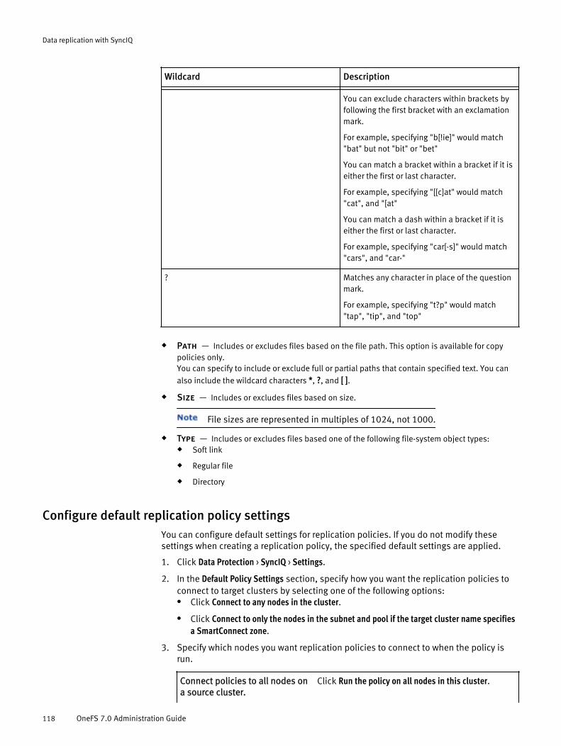
Wildcard Description- -
You can exclude characters within brackets byfollowing the first bracket with an exclamationmark.
For example, specifying "b[!ie]" would match"bat" but not "bit" or "bet"
You can match a bracket within a bracket if it iseither the first or last character.
For example, specifying "[[c]at" would match"cat", and "[at"
You can match a dash within a bracket if it iseither the first or last character.
For example, specifying "car[-s]" would match"cars", and "car-"
? Matches any character in place of the questionmark.
For example, specifying "t?p" would match"tap", "tip", and "top"
u Path — Includes or excludes files based on the file path. This option is available for copypolicies only.You can specify to include or exclude full or partial paths that contain specified text. You can
also include the wildcard characters *, ?, and [ ].
u Size — Includes or excludes files based on size.
File sizes are represented in multiples of 1024, not 1000.
u Type — Includes or excludes files based one of the following file-system object types:u Soft link
u Regular file
u Directory
Configure default replication policy settingsYou can configure default settings for replication policies. If you do not modify thesesettings when creating a replication policy, the specified default settings are applied.
1. Click Data Protection > SyncIQ > Settings.
2. In the Default Policy Settings section, specify how you want the replication policies toconnect to target clusters by selecting one of the following options:l Click Connect to any nodes in the cluster.
l Click Connect to only the nodes in the subnet and pool if the target cluster name specifiesa SmartConnect zone.
3. Specify which nodes you want replication policies to connect to when the policy isrun.
Connect policies to all nodes ona source cluster.
Click Run the policy on all nodes in this cluster.
Data replication with SyncIQ
118 OneFS 7.0 Administration Guide

Connect policies only to nodescontained in a specified subnetand pool.
a. Click Run the policy only on nodes in the specifiedsubnet and pool.
b. From the Subnet and pool list, select the subnetand pool .
Replication does not support dynamic pools.
4. Click Submit.
Create a replication policyYou can create a replication policy with SyncIQ that defines how and when data isreplicated to another Isilon cluster. Configuring a SyncIQ policy is a five-step process.
Configure replication policies carefully. If you modify any of the following policy settingsafter the policy is run, OneFS performs either a full or differential replication the next timethe policy is run:
u Source directory
u Included or excluded directories
u File-criteria statement
u Target cluster name or addressThis applies only if you target a different cluster. If you modify the IP or domain nameof a target cluster, and then modify the replication policy on the source cluster tomatch the new IP or domain name, a full replication is not performed.
u Target directory
Configure basic policy settingsYou must configure basic settings for a replication policy.
1. Click Data Protection > SyncIQ > Policies.
2. Click Add policy.
3. In the Basic Settings area, in the Policy name field, type a name for the replicationpolicy.
4. Optional: To specify a description for the replication policy, in the Description field,type a description.
5. In the Action area, specify the type of replication policy.l To copy all files from the source directory to the target directory, click Copy.
Failback is not supported for copy policies.
l To copy all files from the source directory to the target directory and delete anyfiles on the target directory that are not in the source directory, click Synchronize.
6. In the Run job area, specify whether the job runs according to a schedule, or onlywhen initiated by a user.
Run the policy onlywhen manually initiatedby a user.
Click Manually.
Data replication with SyncIQ
Create a replication policy 119

Run the policyautomatically accordingto a schedule.
a. Click Scheduled.
b. Click Edit schedule.
c. Specify a schedule.
If you configure a replication policy to run more than oncea day, you cannot configure the interval to span acrosstwo calendar days. For example, you can configure areplication policy to run every hour starting at 7:00 PMand ending at 11:00 PM, but you cannot configure areplication policy to run every hour starting at 7:00 PMand ending at 1:00 AM.
What to do nextThe next step in the process of creating a replication policy is specifying sourcedirectories and files.
Specify source directories and filesYou must specify policy source directories and files for a replication policy.
1. In the Source Cluster pane, in the Root directory field, type the full path of the sourcedirectory that you want to replicate to the target cluster.
You must specify a directory contained in /ifs. You cannot specify the /ifs/.snapshot directory or subdirectory of it.
2. Optional: To prevent specific subdirectories of the root directory from beingreplicated, click the Add directory links located to the right of the Include directories andExclude directories fields.
3. Optional: To prevent specific files from being replicated, specify a file-criteriastatement.a. In the File criteria box, click Add criteria.
b. In the Configure File Matching Criteria dialog box, select a file attribute andcomparison operator.
What to do nextThe next step in the process of creating a replication policy is specifying the targetdirectory.
Specify the policy target directoryYou must specify a target cluster and directory to replicate data to.
1. In the Target Cluster area, in the Name or address field, type one of the following:l The fully qualified domain name of any node in the target cluster.
l The host name of any node in the target cluster.
l The name of a SmartConnect zone in the target cluster.
l The IPv4 or IPv6 address of any node in the target cluster.
l localhostThis will replicate data to another directory on the local cluster.
Replication does not support dynamic pools.
2. Specify how you want the replication policy to connect to the target cluster byselecting one of the following options.l Click Connect to any nodes in the cluster.
Data replication with SyncIQ
120 OneFS 7.0 Administration Guide

l Click Connect to only the nodes in the subnet and pool if the target cluster name specifiesa SmartConnect zone.
3. In the Target directory field, type the absolute path of the directory on the target clusterthat you want to replicate data to.
If you specify an existing directory on the target cluster, ensure that the directory isnot the target of another replication policy. If this is a synchronization policy, ensurethat the directory is empty. All files are deleted from the target of a synchronizationpolicy the first time the policy is run.
If the specified target directory does not already exist on the target cluster, thedirectory created the first time the job is run. It is recommended that you do notspecify the /ifs directory. If you specify the /ifs directory, the entire target clusteris set to a read-only state, preventing you from storing any other data on the cluster.
If this is a copy policy, and files exist in the target directory that are also present inthe source directory, those files are overwritten when the job is run.
What to do nextThe next step in the process of creating a replication policy is specifying policy targetsnapshot settings.
Configure policy target snapshot settingsYou can optionally specify target cluster snapshot settings that determine how archivalsnapshots are generated on the target cluster. You can use archival snapshots the sameway that you use regular snapshots for data protection.
One snapshot is always retained on the target cluster to facilitate failover, regardless ofthese settings.
1. In the Target Cluster Archival Snapshots area, next to Create snapshots, specify whether tocreate archival snapshots on the target cluster by selecting one of the followingoptions.l Click Create archival snapshots on the target cluster.
l Click Do not create archival snapshots on the target cluster.
2. Optional: To modify the default alias of the last snapshot created according to thisreplication policy, in the Snapshot alias name field, type a new alias.You can specify the alias name as a snapshot naming pattern. For example, thefollowing naming pattern is valid:
%{PolicyName}-on-%{SrcCluster}-latest
The previous example produces names similar to the following:
newPolicy-on-Cluster1-latest3. Optional: To modify the snapshot naming pattern, in the Snapshot naming pattern field,
type a naming pattern. Each snapshot generated for this replication policy isassigned a name based on this pattern.For example, the following naming pattern is valid:
%{PolicyName}-from-%{SrcCluster}-at-%H:%M-on-%m-%d-%Y
The example produces names similar to the following:
newPolicy-from-Cluster1-at-10:30-on-7-12-20124. Specify whether you want OneFS to automatically delete snapshots generated
according to this policy.
Data replication with SyncIQ
Create a replication policy 121

l Click Do not delete any archival snapshots.
l Click Delete archival snapshots when they expire and specify an expiration period.
What to do nextThe next step in the process of creating a replication policy is configuring advancedpolicy settings.
Configure advanced policy settingsYou can optionally configure advanced settings for a replication policy.
1. In the Workers per node field, specify the maximum number of concurrent processesper node that will perform replication operations.
Do not modify the default setting without consulting Isilon Technical Support.
2. From the Log level list, select the level of logging you want OneFS to perform forreplication jobs.
The following log levels are valid, listed from least to most verbose:
l Click Error.
l Click Notice.
l Click Network Activity.
l Click File Activity.
3. If you want OneFS to perform a checksum on each file data packet that is affected bythe replication job, select the Validate file integrity check box.
If you enable this option, and the checksum values for a file data packet do notmatch, OneFS retransmits the affected packet.
4. To configure shared secret authentication, in the Shared secret field, type a sharedsecret.
To establish this type of authentication, you must configure both the source andtarget cluster to require the same shared secret. For more information, see the IsilonKnowledge Base.
This feature does not perform any encryption.
5. To modify the length of time OneFS retains replication reports for the policy, in theKeep reports for area, specify a length of time.
After the specified expiration period has passed for a report, OneFS automaticallydeletes the report.
Some units of time are displayed differently when you view a report than how theywere originally entered. Entering a number of days that is equal to a correspondingvalue in weeks, months, or years results in the larger unit of time being displayed. Forexample, if you enter a value of 7 days, 1 week appears for that report after it iscreated. This change occurs because OneFS internally records report retention timesin seconds and then converts them into days, weeks, months, or years for display.
6. Specify which nodes you want the replication policy to connect to when the policy isrun.
Connect the policy to all nodes onthe source cluster.
Click Run the policy on all nodes in this cluster.
Data replication with SyncIQ
122 OneFS 7.0 Administration Guide

Connect the policy only to nodescontained in a specified subnetand pool.
l Click Run the policy only on nodes in thespecified subnet and pool.
l From the Subnet and pool list, select thesubnet and pool .
Replication does not support dynamic pools.
7. Specify whether to record information about files that are deleted by synchronizationjobs by selecting one of the following options:l Click Record when a synchronization deletes files or directories.
l Click Do not record when a synchronization deletes files or directories.
This option is applicable for synchronization policies only.
What to do nextThe next step in the process of creating a replication policy is saving the replicationpolicy settings.
Save replication policy settingsOneFS does not begin replicating data according to a replication policy until you save thereplication policy.
Before you beginReview the current settings of the replication policy. If necessary, modify the policysettings.
1. Click Submit.
What to do nextYou can increase the speed at which you can failback a replication policy by creating areplication domain for the source directory of the policy.
Create a SyncIQ domainYou can create a SyncIQ domain to increase the speed at which failback is performed fora replication policy.
Failing back a replication policy requires that a SyncIQ domain be created for the sourcedirectory. OneFS automatically creates a SyncIQ domain during the failback process.However, if you intend on failing back a replication policy, it is recommended that youcreate a SyncIQ domain for the source directory of the replication policy while thedirectory is empty.
1. Click Cluster Management > Operations > Operations Summary.
2. In the Running Jobs area, click Start Job.
3. From the Job list, select Domain Mark.
4. Optional: To specify a priority for the job, from the Priority list, select a priority.
Lower values indicate a higher priority. If you do not specify a priority, the job isassigned the default domain mark priority.
5. Optional: To specify the amount of cluster resources the job is allowed to consume,from the Impact policy list, select an impact policy.
If you do not specify a policy, the job is assigned the default domain mark policy.
6. From the Domain type list, select synciq.
Data replication with SyncIQ
Create a SyncIQ domain 123

7. Ensure that the Delete domain check box is cleared.
8. In the Domain root path field, type the path of a source directory of a replication policy,and then click Start.
Assess a replication policyBefore running a replication policy for the first time, you can view statistics on the filesthat would be affected by the replication without transferring any files. This can be usefulif you want to preview the size of the data set that is affected if you ran the policy.
You can assess only replication policies that have never been run before.
1. Click Data Protection > SyncIQ > Policies.
2. In the Policies area, in the row of the policy you want to assess, click Assess.
3. After the job completes, click Data Protection > SyncIQ > Reports.
4. In the Reports table, in the row of the assessment job, click View details.The report displays data as if the assessment job had transferred the data to thetarget directory. Assessment is displayed in the Transferred column.
Managing replication to remote clustersYou can manually run, view, assess, pause, resume, cancel, resolve, and reset replicationjobs that target other clusters.
After a policy job starts, you can pause the job to suspend replication activities.Afterwards, you can resume the job, continuing replication from the point where the jobwas interrupted. You can also cancel a running or paused replication job if you want tofree the cluster resources allocated for the job. A paused job reserves cluster resourceswhether or not the resources are in use. A cancelled job releases its cluster resources andallows another replication job to consume those resources. No more than five runningand paused replication jobs can exist on a cluster at a time. However, there is no limit tothe number of canceled replication jobs that can exist on a cluster. If a replication jobremains paused for more than a week, OneFS automatically cancels the job.
Start a replication jobYou can manually start a replication job for a replication policy at any time.
If you want to replicate data according to an existing snapshot, at the OneFS commandprompt, run the isi sync policy run command with the --use_snapshot option.Replicating data according to snapshots generated by the SyncIQ tool is not supported.
1. Click Data Protection > SyncIQ > Policies.
2. In the Policies table, in the Actions column of the policy you want to start a replicationjob for, click Start.
Pause a replication jobYou can pause a running replication job and then resume the job later. Pausing areplication job temporarily stops data from being replicated, but does not free the clusterresources replicating the data.
1. Click Data Protection > SyncIQ > Summary.
2. In the Currently Running table, in the Actions column of the job, click Pause.
Data replication with SyncIQ
124 OneFS 7.0 Administration Guide

Resume a replication jobYou can resume a paused replication job.
1. Click Data Protection > SyncIQ > Summary.
2. In the Currently Running table, in the Actions column of the job, click Resume.
Cancel a replication jobYou can cancel a running or paused replication job. Cancelling a replication job stopsdata from being replicated and frees the cluster resources that were replicating data. Youcannot resume a cancelled replication job; in order to restart replication, you must startthe replication policy again.
1. Click Data Protection > SyncIQ > Summary.
2. In the Currently Running table, in the Actions column of the job, click Cancel.
View active replication jobsYou can view information about replication jobs that are currently running or paused.
1. Click Data Protection > SyncIQ > Policies.
2. In the Currently Running and Recently Completed tables, review information about activereplication jobs.
View replication performance informationYou can view information about how many files are sent and the amount of networkbandwidth consumed by replication policies.
1. Click Data Protection > SyncIQ > Policies.
2. In the Network Performance and File Operations tables, view performance information.
Replication job informationYou can view information about replication jobs through the Currently Running and RecentlyCompleted tables.
The following information is displayed in the Currently Running table:
u Run — The status of the job.
u Policy — The name of the associated replication policy.
u Started — The time the job started.
u Elapsed — Indicates how much time has elapsed since the job started.
u Transferred — The number of files that were transferred during the job run, and the totalsize of all transferred files.
u Sync Type — The type of replication being performed. The possible values are Initial, which
indicates that either a differential or a full replication is being performed; Upgrade, which
indicates that a policy-conversion replication is being performed; and Incremental, whichindicates that only modified files are being transferred to the target cluster.
u Source — The source directory on the source cluster.
Data replication with SyncIQ
Resume a replication job 125
u Target — The target directory on the target cluster.
u Actions — Displays any job-related actions that you can perform.
The Recently Completed table contains the following information:
u Run — Indicates the status of the job. A green icon indicates that the last job completedsuccessfully. A yellow icon indicates that the last job did not complete successfully, but that anearlier job did complete successfully. A red icon indicates that jobs have run, but that none ofthe jobs completed successfully. If no icon appears, the job was not run.
u Policy — The name of the associated replication policy.
u Started — The time at which the job started.
u Ended — The time at which the job finished running.
u Duration — Indicates the total amount of time that the job ran for.
u Transferred — The number of files that were transferred during the job run, and the totalsize of all transferred files.
u Sync Type — The type of replication that was performed. The possible values are Initial,which indicates that either a differential or a full replication was performed; Upgrade, whichindicates that a policy-conversion replication occurred after upgrading the OneFS operatingsystem or merging policies; and Incremental, which indicates that only modified files weretransferred to the target cluster.
u Source — The source directory on the source cluster.
u Target — The target directory on the target cluster.
Initiating data failover and failback with SyncIQYou can fail over to a secondary Isilon cluster if, for example, a cluster becomesunavailable. You can also fail back to a primary cluster if, for example, the primary clusterbecomes available again. You can undo a failover if you decide that the failover wasunnecessary, or for testing purposes.
The procedures for failing over and failing back vary if SmartLock directories areinvolved. Failover revert is not supported for SmartLock directories.
Fail over data to a secondary clusterYou can fail over to a secondary Isilon cluster if, for example, a cluster becomesunavailable.
Complete the following procedure for each replication policy you want to fail over.
Before you beginCreate and successfully run a replication policy.
1. On the secondary Isilon cluster, in the Isilon web administration interface, click DataProtection > SyncIQ > Local Targets .
2. In the Local Targets table, in the row of a replication policy, click Allow Writes.
What to do nextRedirect clients to begin accessing the secondary cluster.
Data replication with SyncIQ
126 OneFS 7.0 Administration Guide

Fail over SmartLock directoriesYou can fail over SmartLock directories to a secondary Isilon cluster if, for example, acluster becomes unavailable.
Complete the following procedure for each replication policy you want to fail over.
Before you beginCreate and successfully run a replication policy.
1. On the secondary cluster, in the Isilon web administration interface, click DataProtection > SyncIQ > Local Targets.
2. In the Policies table, in the row of the replication policy, enable writes to the targetdirectory of the policy.l If the last replication job completed successfully and a replication job is not
currently running, click Allow Writes. This will maintain the association between theprimary and secondary cluster.
l If a replication job is currently running, it is recommended that you wait until thereplication job completes, and then click Allow Writes. This will maintain theassociation between the primary and secondary cluster.
l If the primary cluster became unavailable while a replication job was running,click Break. This will break the association between the primary and secondarycluster.
3. If you clicked Break, restore any files left in an inconsistent state.a. Delete all files that were not committed to a WORM state from the target directory.
b. Copy all files from the failover snapshot to the target directory.
Failover snapshots are named according to the following naming pattern:
SIQ-Failover-<policy-name>-<year>-<month>-<day>_<hour>-<minute>-<second>
4. If any SmartLock directory configuration settings, such as an autocommit time period,were specified for the source directory of the replication policy, apply those settingsto the target directory.
What to do nextRedirect clients to begin accessing the secondary cluster.
Failover revertYou can perform a failover revert if, for example, the primary cluster becomes availablebefore data is modified on the secondary cluster. You also might want to perform failoverrevert if you were failing over for testing purposes. Failover revert enables you to replicatedata from the primary cluster to the secondary cluster again.
Failover revert does not migrate data back to the primary cluster. If clients modified dataon the secondary cluster, and you want to migrate the modified data back to the primarycluster, you must fail back to the primary cluster.
Failover revert is not supported for SmartLock directories.
Complete the following procedure for each replication policy you want to fail over.
Before you beginFail over a replication policy.
Data replication with SyncIQ
Fail over SmartLock directories 127
1. On the secondary Isilon cluster, click Data Protection > SyncIQ > Local Targets .
2. In the Local Targets table, in the row of a replication policy, click Disallow Writes, andthen, in the confirmation dialog box, click Yes.
Fail back data to a primary clusterAfter you fail over to a secondary cluster, you can fail back to the primary cluster if, forexample, the primary cluster is available again.
Before you beginFail over a replication policy.
1. On the primary cluster, click Data Protection > SyncIQ > Policies .
2. For each replication policy you want to fail back, in the Policies table, in the row of apolicy you want to fail back, click Prepare re-sync.A mirror policy is created for each replication policy on the secondary cluster.
Mirror policies are named according to the following pattern:
<replication-policy-name>_mirror3. On the secondary cluster, replicate data to the primary cluster by using the mirror
policies.
You can replicate data either by manually starting the mirror policies or by modifyingthe mirror policies and specifying a schedule.
4. Disallow client access to the secondary cluster and run each mirror policy again.
5. On the primary cluster, click Data Protection > SyncIQ > Local Targets .
6. For each mirror policy, in the Local Targets table, in the row of the mirror policy, clickAllow Writes.
7. On the secondary cluster, click Data Protection > SyncIQ > Policies .
8. For each mirror policy, in the Policies table, in the row of the policy, click Prepare re-sync.
What to do nextRedirect clients to begin accessing the primary cluster.
Prepare SmartLock directories for failbackYou must prepare SmartLock directories before you can fail back to them.
You cannot failback to compliance directories or to enterprise directories with theprivileged delete functionality permanently disabled. Instead, you must create newSmartLock directories, and fail back to those empty directories. Failing back to an emptySmartLock directory creates two copies of your data on the primary cluster. If you do nothave space on the primary cluster to store two copies of your data, contact IsilonTechnical Support for information about reformatting your cluster.
Complete the following procedure for each SmartLock directory you want to fail back to.
Before you beginFail over SmartLock directories.
1. On the primary cluster, enable the privileged delete functionality for the directory youwant to fail back to by running the isi worm modify command.
Data replication with SyncIQ
128 OneFS 7.0 Administration Guide

For example, the following command enables privileged delete functionality for /ifs/data/dir:
isi worm modify --path /ifs/data/dir --privdel on2. Disable the autocommit time period for the directory you want to fail back to by
running the isi worm modify command.For example, the following command disables the autocommit time period for /ifs/data/dir:
isi worm modify --path /ifs/data/dir --autocommit none
Fail back SmartLock directoriesAfter you fail over SmartLock directories to a cluster, you can fail back to the cluster youoriginally failed over from if, for example, the original cluster becomes available again.
In some cases, you might be able to fail back a SmartLock directory by following theprocedure for non-SmartLock directory failback. Follow the non-SmartLock directoryprocedure if the following statements are true:
u The SmartLock directory you are failing back is an enterprise directory.
u The privileged delete functionality was not permanently disabled for the directory.
u During the failover process, you maintained the association between the source andtarget cluster.
Complete the following procedure for each replication policy you want to fail back.
Before you beginPrepare SmartLock directories for failback.
1. On the secondary cluster, create a replication policy that meets the followingrequirements:l The source directory is the target directory of the policy you are failing back.
l If you are failing back to an enterprise directory with the privileged deletefunctionality enabled, the target directory of the policy must be the sourcedirectory of the policy you are failing back.
l If you are failing back to a compliance directory, or an enterprise directory with theprivileged delete functionality permanently disabled, the target must be an emptySmartLock directory. The directory must be of the same SmartLock type as thesource directory of the policy you are failing back. For example, if the targetdirectory is a compliance directory, the source must also be a compliancedirectory.
2. Optional: Replicate data to the primary cluster by running the policy you created.
Continue to replicate data until a time when client access to the cluster is minimal.For example, you might wait until a weekend when client access to the cluster isreduced.
3. Disallow client access to the secondary cluster and run the policy that you created.
4. On the primary cluster, click Data Protection > SyncIQ > Local Targets .
5. In the Local Targets table, for the replication policy that you created, click Allow Writes.
6. Optional: If any SmartLock directory configuration settings, such as an autocommittime period, were specified for the source directory of the replication policy, applythose settings to the target directory.
7. Prepare the source directory of the replication policy on the secondary cluster forfailback.
Data replication with SyncIQ
Fail back SmartLock directories 129

For more information, see Prepare SmartLock directories for failback.
8. Begin replicating data by enabling or replacing the replication policy that youoriginally failed over.
What to do nextRedirect clients to begin accessing the primary cluster.
Managing replication policiesYou can modify, view, enable and disable replication policies.
Modify a replication policyYou can modify the settings of a replication policy.
If you modify any of the following policy settings after the policy runs, OneFS performseither a full or differential replication the next time the policy runs:
u Source directory
u Included or excluded directories
u File-criteria statement
u Target clusterThis applies only if you target a different cluster. If you modify the IP or domain nameof a target cluster, and then modify the replication policy on the source cluster tomatch the new IP or domain name, a full replication is not performed.
u Target directory
1. Click Data Protection > SyncIQ > Policies.
2. In the Policies table, click the name of the policy you want to modify.
3. Modify the settings of the replication policy, and then click Submit.
Delete a replication policyYou can delete a replication policy. Once a policy is deleted, it no longer createsreplication jobs. Deleting a replication policy breaks the target association on the targetcluster, and allows writes to the target directory again.
If you want to temporarily suspend a replication policy from creating replication jobs, youcan disable the policy, and then enable the policy again later.
1. Click Data Protection > SyncIQ > Policies.
2. In the Policies table, in the Actions column of the policy, click Delete.
3. In the confirmation dialog box, click Yes.
Enable or disable a replication policyYou can temporarily suspend a replication policy from creating replication jobs, and thenenable it again later.
If you disable a replication policy while an associated replication job is currentlyrunning, the running replication job completes. However, another replication job will notbe created according to the policy until the policy is enabled.
1. Click Data Protection > SyncIQ > Policies.
Data replication with SyncIQ
130 OneFS 7.0 Administration Guide

2. In the Policies table, in the Actions column of the policy, click either Enable or Disable.If neither Enable nor Disable is displayed in the Actions column, verify that anassociated replication job is not running. If an associated replication job is notrunning, ensure that the SyncIQ license is configured on the cluster.
View replication policiesYou can view information about replication policies on a cluster.
1. Click Data Protection > SyncIQ > Policies.
2. In the Policies table, review information about replication policies.
Replication policy informationYou can view information about replication policies through the Policies table.
u Run — If a replication job is running for this policy, indicates whether the job is running orpaused. If no job is running, indicates whether the SyncIQ tool is disabled on the cluster. If noicon appears, indicates that SyncIQ is enabled and that no replication job is currently running.
u Data — Indicates the status of the last run of the job. A green icon indicates that the last jobcompleted successfully. A yellow icon indicates that the last job did not complete successfully,but that an earlier job did complete successfully. If no icon appears, a job for the policy wasnot run.
u Policy — Displays the name of the policy.
u Last Known Good — Indicates when the last successful job ran.
u Schedule — Indicates when the next job is scheduled to run. A value of Manual indicatesthat the job can be run only manually.
u Source — Displays the source directory path.
u Target — Displays the target directory path.
u Actions — Displays any policy-related actions that you can perform.
Replication policy settingsReplication policies are configured to run according to specific replication policy settings.
The following replication policy fields are available through the Isilon web administrationinterface and OneFS command-line interface.
u Policy name — Name of the policy.
u Description — Optional string that describes the policy. For example, the description mightexplain the purpose or function of the policy.
u Action — Describes the how the policy replicates data. All policies copy files from thesource directory to the target directory and update files in the target directory to match files onthe source directory. The action dictates how deleting a file on the source directory affects thetarget. The following values are valid:
u Copy — If a file is deleted in the source directory, the file is not deleted in the targetdirectory.
u Synchronize — Deletes files in the target directory if they are no longer present on thesource. This ensures that an exact replica of the source directory is maintained on thetarget cluster.
Data replication with SyncIQ
View replication policies 131
u Run job — Specifies whether the job is run automatically according to a schedule, or onlymanually when specified by a user.
u Root directory — The full path of the source directory. Data is replicated from the sourcedirectory to the target directory.
u Include directories — Determines which directories are included in replication. If one ormore directories are specified by this setting, any directories that are not specified are notreplicated.
u Exclude directories — Determines which directories are excluded from replication. Anydirectories specified by this setting are not replicated.
u File criteria — Determines which files are excluded from replication.
u Name or address (of target cluster) — The IP address or fully qualified domain nameof the target cluster.
u Target directory — The full path of the target directory. Data is replicated to the targetdirectory from the source directory.
u Create snapshots — Determines whether archival snapshots are generated on the targetcluster.
u Snapshot alias name — Specifies an alias for the latest archival snapshot taken on thetarget cluster.
u Snapshot naming pattern — Specifies how archival snapshots are named on the targetcluster.
u Snapshot expiration — Specifies how long archival snapshots are retained on the targetcluster before they are automatically deleted by the system.
u Workers per node — Specifies the number of workers per node that are generated byOneFS to perform each replication job for the policy.
u Log level — Specifies the amount of information that is recorded in the logs for replicationjobs.More verbose options include all information from less verbose options. The following listdescribes the log levels from least to most verbose:
u Notice — Includes job and process-level activity, including job starts and stops, andworker coordination information. It is recommended that you select this option.
u Error — Includes events related to specific types of failures.
u Network Activity — Includes more job-level activity and work-item information,including specific paths and snapshot names.
u File Activity — Includes a separate event for each action taken on a file. Do not selectthis option without first consulting Isilon Technical Support.
Replication logs are typically used only for debugging purposes. If necessary, you can log in toa node through the command-line interface and view the contents of the /var/log/isi_migrate.log file on the node.
u Check integrity — Determines whether OneFS performs a checksum on each file datapacket that is affected by a replication job. If a checksum value does not match, OneFSretransmits the affected file data packet.
u Shared secret — Determines whether OneFS references a shared secret on the source andtarget cluster to prevent certain types of attacks.
This feature does not perform any encryption.
Data replication with SyncIQ
132 OneFS 7.0 Administration Guide
u Keep reports for — Specifies how long replication reports are kept before they areautomatically deleted by OneFS.
u Source node restrictions — Specifies whether replication jobs connect to any nodes inthe cluster or if jobs can connect only to nodes in a specified subnet and pool.
u Delete on synchronization — Determines whether OneFS records when asynchronization job deletes files or directories on the target cluster.
The following replication policy fields are available only through the OneFS command-lineinterface.
u Password — Specifies a password to access the target cluster.
u Max reports — Specifies the maximum number of replication reports that are retained forthis policy.
u Diff sync — Determines whether full or differential replications are performed for this policy.Full or differential replications are performed the first time a policy is run and after a policy isreset.
u Rename pattern — Determines whether snapshots generated for the replication policy onthe source cluster are deleted when the next replication policy is run. If specified, snapshotsthat are generated for the replication policy on the source cluster are retained and renamedaccording to the specified rename pattern. If not specified, snapshots generated on the sourcecluster are deleted. Specifying this setting does not require that the SnapshotIQ license beconfigured on the cluster.
u Rename expiration — If snapshots generated for the replication policy on the sourcecluster are retained, specifies an expiration period for the snapshots.
Managing replication to the local clusterYou can control certain operations of replication jobs that target the local cluster.
You can cancel a currently running job that targets the local cluster, or you can break theassociation between a policy and its specified target. Breaking a source and targetcluster association causes the replication policy to perform a full replication the next timea job for the policy is run.
Cancel replication to the local clusterYou can cancel a replication job that is targeting the local cluster.
1. Click Data Protection > SyncIQ > Local Targets.
2. In the Local Targets table, specify whether to cancel a specific replication job or allreplication jobs targeting the local cluster.l In the Actions column of a job, click Cancel.
l Click Cancel all running target policies.
Break local target associationYou can break the association between a replication policy and the local cluster.Breaking this association requires you to reset the replication policy before you can runthe policy again.
Depending on the amount of data being replicated, a full or differential replication cantake a very long time to complete.
Data replication with SyncIQ
Managing replication to the local cluster 133

1. Click Data Protection > SyncIQ > Local Targets.
2. In the Local Targets table, in the Actions column of the policy, click Break.
3. In the Confirm dialog box, click Yes.
View replication jobs targeting the local clusterYou can view information about currently running replication jobs that are replicatingdata to the local cluster.
1. Click Data Protection > SyncIQ > Local Targets.
2. In the Local Targets table, view information about replication jobs.
Remote replication policy informationYou can view information about replication policies that are currently targeting the localcluster.
The following information is displayed in the Local Targets table:
u Run — The status of the last run of the job.The following icons might appear:
u Green — Indicates that the last job completed successfully.
u Yellow — Indicates that the last job did not complete successfully, but that an earlierjob did complete successfully.
u Red — Indicates that jobs have run, but that none of the jobs completed successfully.
A yellow or red icon might indicate that the policy is in an unrunnable state.You can view more detailed policy-status information and, if necessary, resolve thesource-target association, through the web administration interface on the sourcecluster.
u Policy — The name of the replication policy.
u Updated — The time when data about the policy or job was last collected from the sourcecluster.
u Source — The source directory on the source cluster.
u Target — The target directory on the target cluster.
u Coordinator IP — The IP address of the node on the source cluster that is acting as thejob coordinator.
u Actions — Displays any job-related actions that you can perform.
Managing replication performance rulesYou can manage the impact of replication on cluster performance by creating rules thatlimit the network traffic created and the rate at which files are sent by replication jobs.
Create a network traffic ruleYou can create a network traffic rule that limits the amount of network traffic thatreplication policies are allowed to generate during a specified time period.
1. Click Data Protection > SyncIQ > Performance .
2. In the Network Rules area, click Add rule.
Data replication with SyncIQ
134 OneFS 7.0 Administration Guide

3. In the Edit Limit dialog box, in the Limit (bits/sec) area, specify the maximum number ofbits per second that replication rules are allowed to send.
4. In the Days area, select the days of the week that you want to apply the rule.
5. In the Start and End areas, specify the period of time that you want to apply the rule.
6. Optional: To add an optional description of this network traffic rule, in the Descriptionbox, type a description.
7. Click Enabled.
If you do not select Enabled, the rule is disabled by default.
8. Click Submit.
Create a file operations ruleYou can create a file-operations rule that limits the number of files that replication jobscan send per second.
1. Click Data Protection > SyncIQ > Performance .
2. In the File Operations Rules area, click Add rule.
3. In the Edit Limit dialog box, in the Limit (files/sec) area, specify the maximum numberof files per second that replication rules are allowed to send.
4. In the Days area, select the days that you want to apply the rule.
5. In the Start and End areas, specify the period of time that you want to apply the rule.
6. Optional: To add an optional description of this file-operations rule, in the Descriptionbox, type a description.
7. Click Enabled.
If you do not select Enabled, the rule is disabled by default.
8. Click Submit.
Modify a performance ruleYou can modify a performance rule.
1. Click Data Protection > SyncIQ > Performance .
2. In either the Network Rules table or the File Operation Rules table, in the row of the ruleyou want to modify, click Edit.
3. In the Edit Limit dialog box, modify rule settings as needed, and then click Submit.
Delete a performance ruleYou can delete a performance rule.
1. Click Data Protection > SyncIQ > Performance .
2. In either the Network Rules table or the File Operation Rules table, in the row of the rule,click Delete.
3. In the Confirm dialog box, click Yes.
Data replication with SyncIQ
Create a file operations rule 135

Enable or disable a performance ruleYou can disable a performance rule to temporarily prevent the rule from being enforced.You can also enable a performance rule after it has been disabled.
1. Click Data Protection > SyncIQ > Performance .
2. In either the Network Rules table or the File Operation Rules table, in the row of the rule,click Edit.
3. In the Edit Limit dialog box, click either Enabled or Disabled.
4. Click Submit.
View performance rulesYou can view performance rules.
1. Click Data Protection > SyncIQ > Performance .
2. In either the Network Rules table or the File Operation Rules table, view performancerules.
Managing replication reportsIn addition to viewing replication reports, you can configure how long reports are retainedon the cluster. You can also request that the cluster immediately delete any reports thathave passed their expiration period. If necessary, you can also rebuild the databases thatcontain replication reports.
Configure default replication report settingsYou can configure the default amount of time that OneFS retains replication reports onthe cluster and the maximum number of reports that OneFS retains for each replicationpolicy.
1. Click Data Protection > SyncIQ > Settings.
2. In the Report Settings area, in the Retain reports for area, specify how long you want toretain replication reports for.
After the specified expiration period has passed for a report, OneFS automaticallydeletes the report.
Some units of time are displayed differently when you view a report than how youoriginally enter them. Entering a number of days that is equal to a correspondingvalue in weeks, months, or years results in the larger unit of time being displayed. Forexample, if you enter a value of 7 days, 1 week appears for that report after it iscreated. This change occurs because OneFS internally records report retention timesin seconds and then converts them into days, weeks, months, or years for display.
3. In the Number of reports to keep per policy field, type the maximum number of reportsyou want to retain at a time for a replication policy.
4. Click Submit.
Delete replication reportsReplication reports are routinely deleted by OneFS after the reports are retained past theirgiven expiration date or when the number of reports exceeds the maximum number
Data replication with SyncIQ
136 OneFS 7.0 Administration Guide
specified for a report. Excess reports are periodically deleted by OneFS; however, you canmanually delete all excess replication reports at any time.
1. Open a secure shell (SSH) connection to any node in the cluster and log in.
2. Delete excess replication reports by running the following command:isi sync report rotate
What to do nextIf OneFS did not delete the desired number of replication reports, configure thereplication report settings, and then repeat this procedure.
View replication reportsYou can view replication reports.
1. Click Data Protection > SyncIQ > Reports.
2. In the Reports table, view replication reports.
3. Optional: View details of a replication report by clicking View Details in the Actionscolumn of the report you want to view.
Replication report informationYou can view information about replication reports.
The following information is displayed in the Reports table:
u Status — The status of the last run of the job.The following icons are displayed:
u Green — Indicates that the last job completed successfully.
u Yellow — Indicates that the last job did not complete successfully, but that an earlierjob did complete successfully.
u Red — Indicates that jobs have run, but were unsuccessful.
If no icon appears, the job was not run.
u Policy — The name of the associated policy for the job. You can view or edit settings for thepolicy by clicking the policy name.
u Started, Ended, and Duration — Indicates when the job started and ended, and theduration of the job.
u Transferred — The total number of files that were transferred during the job run, and thetotal size of all transferred files. For assessed policies, Assessment appears.
u Sync Type — The action that was performed by the replication job.The following actions are displayed:
u Initial Sync — Indicates that either a differential or a full replication was performed.
u Incremental Sync — Indicates that only modified files were transferred to the targetcluster.
u Failover / Failback Allow Writes — Indicates that writes were enabled on a targetdirectory of a replication policy.
u Failover / Failback Dissallow Writes — Indicates that an allow writes operationwas undone.
Data replication with SyncIQ
View replication reports 137

u Failover / Failback Resync Prep — Indicates that an association between files onthe source cluster and files on the target cluster was created. This is the first step in thefailback preparation process.
u Failover / Failback Resync Prep Domain Mark — Indicates that a SyncIQ domainwas created for the source directory. This is the second step in the failback preparationprocess.
u Failover / Failback Resync Prep Restore — Indicates that a source directory wasrestored to the last recovery point. This is the third step in the failback preparationprocess.
u Failover / Failback Resync Prep Finalize — Indicates that a mirror policy wascreated on the target cluster. This is the last step in the failback preparation process.
u Upgrade — Indicates that a policy-conversion replication occurred after upgrading theOneFS operating system or merging policies.
u Source — The source directory on the source cluster.
u Target — The target directory on the target cluster.
u Actions — Displays any report-related actions that you can perform.
Managing failed replication jobsIf a replication job fails due to an error, OneFS might disable the correspondingreplication policy. If a replication policy is disabled, the policy cannot be run. Replicationjobs are often disabled due to the IP or hostname of the target cluster being modified.
To resume replication for a disabled policy, you must either fix the error that caused thepolicy to be disabled, or reset the replication policy. It is recommended that you attemptto fix the issue rather than reset the policy. If you believe you have fixed the error, youcan return the replication policy to an enabled state by resolving the policy. You can thenrun the policy again to test whether the issue was fixed. If you are unable to fix the issue,you can reset the replication policy. Resetting the policy causes a full or differentialreplication to be performed the next time the policy is run.
Depending on the amount of data being synchronized or copied, a full anddifferential replications can take a very long time to complete.
Resolve a replication policyIf a replication job encounters an error, and you fix the issue that caused the error, youcan resolve a replication policy. Resolving a replication policy enables you to run thepolicy again. If you cannot resolve the issue that caused the error, you can reset thereplication policy.
1. Click Data Protection > SyncIQ > Policies.
2. In the Policies table, in the Actions column of the policy, click Resolve.
3. In the confirmation dialog box, type yes and then click Yes.
Reset a replication policyIf a replication job encounters an error that you cannot resolve, you can reset thecorresponding replication policy. Resetting a policy causes OneFS to perform a full ordifferential replication the next time the policy is run.
Resetting a replication policy deletes the snapshot for the source-cluster snapshot.
Data replication with SyncIQ
138 OneFS 7.0 Administration Guide

Depending on the amount of data being replicated, a full or differential replication cantake a very long time to complete. Reset a replication policy only if you cannot fix theissue that caused the replication error. If you fix the issue that caused the error, resolvethe policy instead of resetting the policy.
1. Click Data Protection > SyncIQ > Policies.
2. In the Policies table, in the Actions column of a policy, click Reset.
3. In the Confirm dialog box, type yes and then click Yes.
Perform a full or differential replicationAfter you reset a replication policy, you must perform either a full or differentialreplication.
Before you beginReset a replication policy.
1. Open a secure shell (SSH) connection to any node in the cluster and log in throughthe root or compliance administrator account.
2. Specify the type of replication you want to perform by running the isi sync policymodify command.l To perform a full replication, disable the --diff_sync option.
For example, the following command disables differential synchronization fornewPolicy:
isi sync policy modify newPolicy --diff_sync offl To perform a differential replication, enable the --diff_sync option.
For example, the following command enables differential synchronization fornewPolicy:
isi sync policy modify newPolicy --diff_sync on3. Run the policy by running the isi sync policy run command.
For example, the following command runs newPolicy:
isi sync policy run newPolicy
Data replication with SyncIQ
Perform a full or differential replication 139

Data replication with SyncIQ
140 OneFS 7.0 Administration Guide

CHAPTER 6
Data layout with FlexProtect
An Isilon cluster is designed to continuously serve data, even when one or morecomponents simultaneously fail. OneFS ensures data availability by striping or mirroringdata across the cluster. If a cluster component fails, data stored on the failed componentis available on another component. After a component failure, lost data is restored onhealthy components by the FlexProtect proprietary system.
Data protection is specified at the file level, not the block level, enabling the system torecover data quickly. Because all data, metadata, and parity information is distributedacross all nodes in the cluster, an Isilon cluster does not require a dedicated parity nodeor drive. This ensures that no single node limits the speed of the rebuild process.
u File striping.........................................................................................................142u Data protection levels.........................................................................................142u FlexProtect data recovery.....................................................................................142u Managing protection levels.................................................................................144u Data protection level information........................................................................144u Data protection level disk space usage................................................................145
Data layout with FlexProtect 141

File stripingOneFS uses the back-end network to automatically allocate and stripe data across nodesand disks in the cluster. OneFS protects data as the data is being written. No separateaction is necessary to stripe data.
OneFS breaks files into smaller logical chunks called stripes before writing the files todisk; the size of each file chunk is referred to as the stripe unit size. Each OneFS block is8 KB, and a stripe unit consists of 16 blocks, for a total of 128 KB per stripe unit. During awrite, OneFS breaks data into stripes and then logically places the data in a stripe unit.As OneFS stripes data across the cluster, OneFS fills the stripe unit according to thenumber of nodes and protection level.
OneFS can continuously reallocate data and make storage space more usable andefficient. As the cluster size increases, OneFS stores large files more efficiently.
Data protection levelsData protection levels determine the amount of redundant data created on the cluster toensure that data is protected against component failures. OneFS enables you to modifythe protection levels in real time, while clients are reading and writing data on the cluster.
OneFS provides several levels of configurable data protection settings. You can modifythese protection settings at any time without rebooting or taking the cluster or file systemoffline. The configured protection level allows up to four failures at one time on distinctnodes. When planning your storage solution, keep in mind that increasing the parityprotection settings reduces write performance and requires additional storage space forthe increased number of nodes.
OneFS uses the Reed Solomon algorithm for N+M protection. In the N+M data protectionmodel, N represents the number of data-stripe units, and M represents the number ofsimultaneous node or drive failures—or a combination of node and drive failures—thatthe cluster can withstand without incurring data loss. N must be larger than M.
In addition to N+M data protection levels, OneFS also supports data mirroring from 2x-8x,allowing from two to eight mirrors of the specified content. In terms of overall clusterperformance and resource consumption, N+M protection is often more efficient thanmirrored protection. However, because read and write performance is reduced for N+Mprotection, data mirroring might be faster for data that is updated often and is small insize. Data mirroring requires significant overhead and might not always be the best data-protection method. For example, if you enable 3x mirroring, the specified content isduplicated three times on the cluster; depending on the amount of content mirrored, thiscan consume a significant amount of storage space.
FlexProtect data recoveryOneFS uses the FlexProtect proprietary system to detect and repair files and directoriesthat are in a degraded state due to node or drive failures.
OneFS protects data in the cluster based on the configured protection policy. OneFSrebuilds failed disks, uses free storage space across the entire cluster to further preventdata loss, monitors data, and migrates data off of at-risk components.
OneFS distributes all data and error-correction information across the cluster and ensuresthat all data remains intact and accessible even in the event of simultaneous componentfailures. Under normal operating conditions, all data on the cluster is protected againstone or more failures of a node or drive. However, if a node or drive fails, the clusterprotection status is considered to be in a degraded state until the data is protected byOneFS again. OneFS reprotects data by rebuilding data in the free space of the cluster.While the protection status is in a degraded state, data is more vulnerable to data loss.
Data layout with FlexProtect
142 OneFS 7.0 Administration Guide

Because data is rebuilt in the free space of the cluster, the cluster does not require adedicated hot-spare node or drive in order to recover from a component failure. Becausea certain amount of free space is required to rebuild data, it is recommended that youreserve adequate free space through the virtual hot spare feature.
As a cluster grows larger, data restriping operations become faster. As you add morenodes, the cluster gains more CPU, memory, and disks to use during recovery operations.
SmartfailOneFS protects data stored on failing nodes or drives through a process calledsmartfailing.
During the smartfail process, OneFS places a device into quarantine. Quarantineddevices can be used only for read operations. While the device is quarantined, OneFSreprotects the data on the device by distributing the data to other devices. After all datamigration is complete, OneFS logically removes the device from the cluster, the clusterlogically changes its width to the new configuration, and the node or drive can bephysically replaced.
OneFS automatically smartfails devices only as a last resort. Although you can manuallysmartfail nodes or drives, it is recommended that you first consult Isilon TechnicalSupport.
Occasionally a device might fail before OneFS detects a problem. If a drive fails withoutbeing smartfailed, OneFS automatically starts rebuilding the data to available free spaceon the cluster. However, because a node might recover from a failure, if a node fails,OneFS does not start rebuilding data unless the node is logically removed from thecluster.
Node failuresBecause node loss is often a temporary issue, OneFS does not automatically startreprotecting data when a node fails or goes offline. If a node reboots, the file system doesnot need to be rebuilt because it remains intact during the temporary failure.
If an N+1 data protection level is configured, and one node fails, all of the data is stillaccessible from every other node in the cluster. If the node comes back online, the noderejoins the cluster automatically without requiring a full rebuild.
To ensure that data remains protected, if you physically remove a node from the cluster,you must also logically remove the node from the cluster. After you logically remove anode, the node automatically reformats its own drives, and resets itself to the factorydefault settings. The reset occurs only after OneFS has confirmed that all data has beenreprotected. You can logically remove a node using the smartfail process. It is importantthat you use the smartfail process only when you want to permanently remove a nodefrom the cluster.
If you remove a failed node before adding a new node, data stored on the failed nodemust be rebuilt in the free space in the cluster. After the new node is added, the data isthen distributed to the new node. It is more efficient to add a replacement node to thecluster before failing the old node because OneFS can immediately use the replacementnode to rebuild the data stored on the failed node.
Data layout with FlexProtect
Smartfail 143
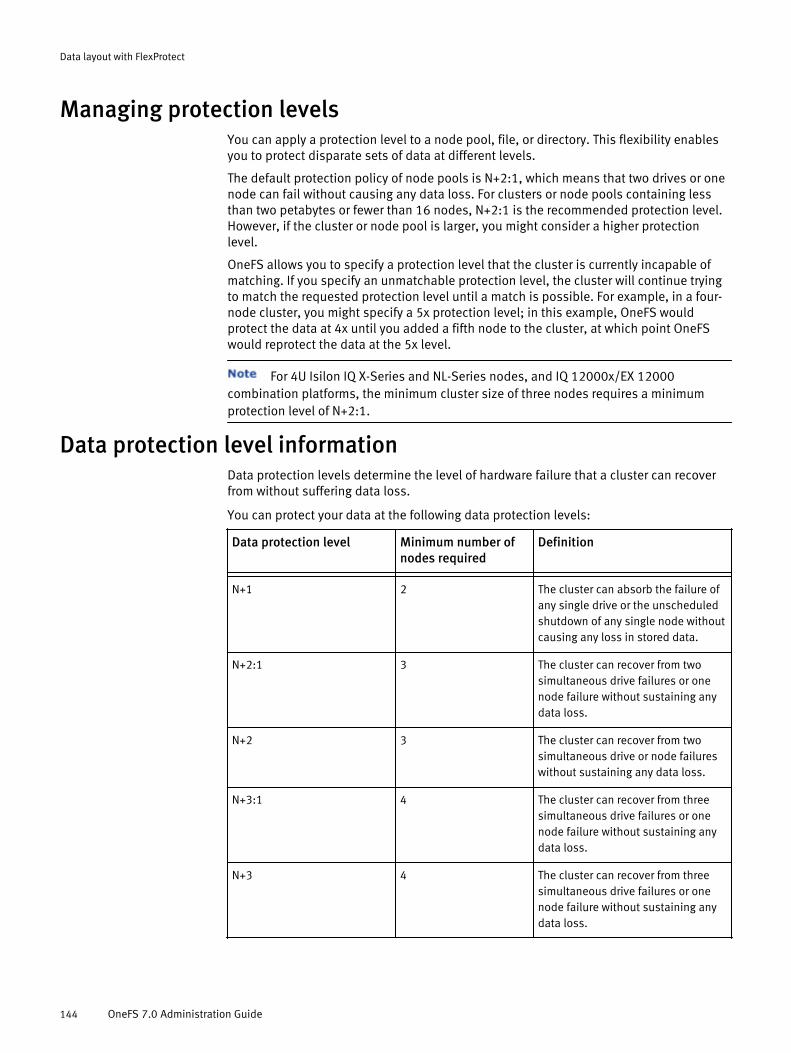
Managing protection levelsYou can apply a protection level to a node pool, file, or directory. This flexibility enablesyou to protect disparate sets of data at different levels.
The default protection policy of node pools is N+2:1, which means that two drives or onenode can fail without causing any data loss. For clusters or node pools containing lessthan two petabytes or fewer than 16 nodes, N+2:1 is the recommended protection level.However, if the cluster or node pool is larger, you might consider a higher protectionlevel.
OneFS allows you to specify a protection level that the cluster is currently incapable ofmatching. If you specify an unmatchable protection level, the cluster will continue tryingto match the requested protection level until a match is possible. For example, in a four-node cluster, you might specify a 5x protection level; in this example, OneFS wouldprotect the data at 4x until you added a fifth node to the cluster, at which point OneFSwould reprotect the data at the 5x level.
For 4U Isilon IQ X-Series and NL-Series nodes, and IQ 12000x/EX 12000combination platforms, the minimum cluster size of three nodes requires a minimumprotection level of N+2:1.
Data protection level informationData protection levels determine the level of hardware failure that a cluster can recoverfrom without suffering data loss.
You can protect your data at the following data protection levels:
Data protection level Minimum number ofnodes required
Definition
- - -N+1 2 The cluster can absorb the failure of
any single drive or the unscheduledshutdown of any single node withoutcausing any loss in stored data.
N+2:1 3 The cluster can recover from twosimultaneous drive failures or onenode failure without sustaining anydata loss.
N+2 3 The cluster can recover from twosimultaneous drive or node failureswithout sustaining any data loss.
N+3:1 4 The cluster can recover from threesimultaneous drive failures or onenode failure without sustaining anydata loss.
N+3 4 The cluster can recover from threesimultaneous drive failures or onenode failure without sustaining anydata loss.
Data layout with FlexProtect
144 OneFS 7.0 Administration Guide

Data protection level Minimum number ofnodes required
Definition
- - -N+4 5 The cluster can recover from four
simultaneous drive or node failureswithout sustaining any data loss.
Nx (Data mirroring) N
For example, 5x requiresa minimum of five nodes.
The cluster can recover from N - 1node failures without sustaining dataloss. For example, 5x protectionmeans that the cluster can recoverfrom four node failures
Data protection level disk space usageIncreasing protection levels increases the amount of space consumed by the data on thecluster.
The parity overhead for N + M protection levels depends on the file size and the numberof nodes in the cluster. The percentage of parity overhead declines as the cluster getslarger.
The following table describes the estimated amount of overhead depending on the N+Mprotection level and the size of the cluster or node pool. The table is for informationalpurposes only and does not reflect protection level recommendations based on clustersize.
Number ofnodes
+1 +2:1 +2 +3:1 +3 +4
- - - - - - -3 2 +1 (33%) 4 + 2 (33%) 3x — — —
4 3 +1 (25%) 6 + 2 (25%) 2 + 2 (50%) 9 + 3 (25%) 4x —
5 4 +1 (20%) 8 + 2 (20%) 3 + 2 (40%) 12 + 3(20%)
4x 5x
6 5 +1 (17%) 10 + 2(17%)
4 + 2 (33%) 15 + 3(17%)
3 + 3 (50%) 5x
7 6 +1 (14%) 12 + 2(14%)
5 + 2 (29%) 15 + 3(17%)
4 + 3 (43%) 5x
8 7 +1 (13%) 14 + 2(12.5%)
6 + 2 (25%) 15 + 3(17%)
5 + 3 (38%) 4 + 4 (50%)
9 8 +1 (11%) 16 + 2(11%)
7 + 2 (22%) 15 + 3(17%)
6 + 3 (33%) 5 + 4 (44%)
10 9 +1 (10%) 16 + 2(11%)
8 + 2 (20%) 15 + 3(17%)
7 + 3 (30%) 6 + 4 (40%)
12 11 +1 (8%) 16 + 2(11%)
10 + 2(17%)
15 + 3(17%)
9 + 3 (25%) 8 + 4 (33%)
14 13 + 1 (7%) 16 + 2(11%)
12 + 2(14%)
15 + 3(17%)
11 + 3(21%)
10 + 4(29%)
Data layout with FlexProtect
Data protection level disk space usage 145

Number ofnodes
+1 +2:1 +2 +3:1 +3 +4
- - - - - - -16 15 + 1 (6%) 16 + 2
(11%)14 + 2(13%)
15 + 3(17%)
13 + 3(19%)
12 + 4(25%)
18 16 + 1 (6%) 16 + 2(11%)
16 + 2(11%)
15 + 3(17%)
15 + 3(17%)
14 + 4(22%)
20 16 + 1 (6%) 16 + 2(11%)
16 + 2(11%)
16 + 3(16%)
16 + 3(16%)
16 + 4(20%)
30 16 + 1 (6%) 16 + 2(11%)
16 + 2(11%)
16 + 3(16%)
16 + 3(16%)
16 + 4(20%)
The parity overhead for mirrored data protection is not affected by the number of nodes inthe cluster. The following table describes the parity overhead for each mirrored dataprotection level.
2x 3x 4x 5x 6x 7x 8x- - - - - - -50% 67% 75% 80% 83% 86% %88
Data layout with FlexProtect
146 OneFS 7.0 Administration Guide

CHAPTER 7
NDMP backup
OneFS enables you to back up and restore file-system data through the Network DataManagement Protocol (NDMP). From a backup server, you can direct backup and recoveryprocesses between an Isilon cluster and backup devices such as tape devices, mediaservers, and virtual tape libraries (VTLs).
OneFS supports both NDMP three-way backup and NDMP two-way backup. During athree-way NDMP backup operation, a data management application (DMA) on a backupserver instructs the cluster to start backing up data to a tape media server that is eitherattached to the LAN or directly attached to the DMA. During a two-way NDMP backup, aDMA on a backup server instructs a Backup Accelerator node on the cluster to startbacking up data to a tape media server that is attached to the Backup Accelerator node.Two-way NDMP backup is the most efficient method in terms of cluster resourceconsumption; however, two-way NDMP backup requires that one or more BackupAccelerator nodes be attached to the cluster. In both the two-way and three-way NDMPbackup models, file history data is transferred from the cluster to a backup server.
Before a backup begins, OneFS creates a snapshot of the targeted directory. OneFS thenbacks up the snapshot, which ensures that the backup image represents a specific pointin time. After the backup is completed or canceled, OneFS automatically deletes thesnapshot. You do not need to configure a SnapshotIQ license on the cluster to performNDMP backups. However, if a SnapshotIQ license is configured on the cluster, you cangenerate a snapshot through the SnapshotIQ tool, and then back up the snapshot. If youback up a snapshot that you generated, OneFS does not create another snapshot for thebackup.
If you are backing up SmartLock compliance directories, it is recommended thatyou do not specify autocommit time periods for the SmartLock directories.
u NDMP two way backup........................................................................................148u NDMP protocol support.......................................................................................148u Supported DMAs.................................................................................................148u NDMP hardware support.....................................................................................149u NDMP backup limitations....................................................................................149u NDMP performance recommendations................................................................149u Excluding files and directories from NDMP backups............................................151u Configuring basic NDMP backup settings............................................................152u Create an NDMP user account.............................................................................153u Managing NDMP user accounts...........................................................................154u Managing NDMP backup devices.........................................................................154u Managing NDMP backup ports............................................................................156u Managing NDMP backup sessions.......................................................................157u View NDMP backup logs......................................................................................159u NDMP environment variables..............................................................................159
NDMP backup 147
NDMP two way backupTo perform NDMP two-way backups, you must attach a Backup Accelerator node to theIsilon cluster, attach one or more tape devices to the Backup Accelerator node. Beforetape devices can be used for backup, you must detect the devices through OneFS.
Each Backup Accelerator node contains Fibre Channel ports through which you canconnect tape and media changer devices or Fibre Channel switches. If you connect a FibreChannel switch to a port, you can connect multiple tape and media changer devicesthrough a single port; for more information, see your Fibre Channel switch documentationabout zoning the switch to allow communication between the Backup Accelerator nodeand the tape and media changer devices.
If you attach devices to a Backup Accelerator node, the cluster detects the devices whenyou start or restart the Backup Accelerator node or when you rescan the Fibre Channelports to discover devices. If a cluster detects a tape or media changer device, it creates adevice entry for each path to the device. If you connect a device through a Fibre Channelswitch, multiple paths can exist for a single device. For example, if you connect a tapedevice to a Fibre Channel switch, and then connect the Fibre Channel switch to two FibreChannel ports, OneFS creates two entries for the device, one for each path.
If you perform an NDMP two-way backup operation, you must assign static IPaddresses to the Backup Accelerator node. If you connect to the cluster through a DataManagement Application (DMA), you must connect to the IP address of a BackupAccelerator node. If you perform an NDMP three-way backup, you can connect to anynode in the cluster.
NDMP protocol supportYou can back up cluster data through NDMP version 3 or 4.
OneFS supports the following features of NDMP versions 3 and 4:
u Full (0) NDMP backups
u Level-based (1-9) NDMP incremental backups
u Token-based NDMP backups
u NDMP TAR and dump types
If you specify the NDMP dump backup type, the backup will be stored on thebackup device in TAR format.
u Path-based and dir/node file history format.
u Direct Access Restore (DAR)
u Directory DAR (DDAR)
u Including and excluding specific files and directories from backup
u Backup of file attributes
u Backup of Access Control Lists (ACLs)
u Backup of Alternate Data Streams (ADSs)
Supported DMAsNDMP backups are coordinated by a data management application (DMA) that runs on abackup server.
OneFS supports the following DMAs:
NDMP backup
148 OneFS 7.0 Administration Guide

u Symantec NetBackup
u EMC Networker
u Symantec Backup Exec
u IBM Tivoli Storage Manager
u Quest Software NetVault
u CommVault Simpana
u Atempo Time Navigator
NDMP hardware supportOneFS can backup data to specific backup devices.
OneFS supports the following types of emulated and physical tape devices:
u LTO-3
u LTO-4
u LTO-5
OneFS supports the following virtual tape libraries (VTLs):
u FalconStor VTL 5.20
u Data Domain VTL 5.1.04 or later
Point-to-point (also known as direct) topologies are not supported for VTLs. VTLs mustinclude a Fibre Channel switch.
NDMP backup limitationsThe OneFS NDMP backup functionality includes the following limitations:
u OneFS does not back up file system configuration data, such as file protection levelpolicies and quotas.
u OneFS does not support multiplexing across multiple streams.
u OneFS does not support shared storage options to shared media drives.
u OneFS does not support restoring data from another file system other than OneFS.However, you can migrate data from a NetApp storage system to OneFS.
u Backup Accelerator nodes cannot interact with more than 1024 device paths,including paths of tape and media changer devices. For example, if each device hasfour paths, you can connect 256 devices to a Backup Accelerator node. If each devicehas two paths, you can connect 512 devices.
u OneFS does not support more than 64 concurrent NDMP sessions.
NDMP performance recommendationsTo improve the speed and efficiency of NDMP backup and restore operations, considerimplementing these recommended best practices.
General performance recommendationsThe following recommended best practices can improve performance of NDMP backupand restore operations:
u If you are backing up multiple directories that contain small files, set up a separateschedule for each directory.
u If you are performing three-way NDMP backups, run multiple NDMP sessions onmultiple nodes.
NDMP backup
NDMP hardware support 149

u Do not perform both three-way and two-way NDMP backup operations on the samecluster.
u Install the latest patches from Isilon and your data management application (DMA)vendor when available.
u Restore files through Direct Access Restore (DAR) and Directory DAR (DDAR). This isespecially recommended if you restore files frequently. However, it is recommendedthat you do not use DAR to restore a full backup or a large number of files.
u Use the largest tape record size available for your version of OneFS. The largest taperecord size for OneFS versions 6.5.5 and later is 256 k. The largest tape record sizefor versions of OneFS earlier than 6.5.5 is 128 k.
u If possible, do not include or exclude files from backup. Including or excluding filescan affect backup performance, due to filtering overhead during tree walks.
u Limit the depth of nested subdirectories in your file system.
u Limit the number of files in a directory. Distribute files across multiple directoriesinstead of including a large number of files in a single directory.
Networking recommendationsThe following best practices are recommended for configuring the connection between acluster and NDMP backup devices:
u Assign static IP addresses to Backup Accelerator nodes.
u Configure SmartConnect zones that are dedicated to NDMP backup activity.
It is recommended that you connect NDMP sessions only throughSmartConnect zones that are exclusively used for NDMP backup.
u Configure multiple policies when scheduling backup operations, with each policycapturing a portion of the file system. Do not attempt to back up the entire file systemthrough a single policy.
Backup Accelerator recommendationsThe following best practices are recommended if you are performing NDMP two-waybackups:
u Run four concurrent streams per Backup Accelerator node.
This is recommended only if you are backing up a significant amount of data.Running four concurrent streams might not be possible or necessary for smallerbackups.
u Attach more Backup Accelerator nodes to larger clusters. The recommended numberof Backup Accelerator nodes depends on the type of nodes that are included in thecluster. The following table lists the recommended number of Backup Acceleratornodes to include in a cluster.
Node type Recommended number of nodes per Backup Accelerator node
i-Series 5
X-Series 3
NL-Series 3
S-Series 3
NDMP backup
150 OneFS 7.0 Administration Guide
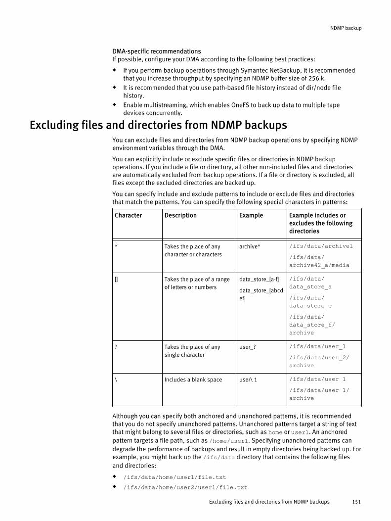
DMA-specific recommendationsIf possible, configure your DMA according to the following best practices:
u If you perform backup operations through Symantec NetBackup, it is recommendedthat you increase throughput by specifying an NDMP buffer size of 256 k.
u It is recommended that you use path-based file history instead of dir/node filehistory.
u Enable multistreaming, which enables OneFS to back up data to multiple tapedevices concurrently.
Excluding files and directories from NDMP backupsYou can exclude files and directories from NDMP backup operations by specifying NDMPenvironment variables through the DMA.
You can explicitly include or exclude specific files or directories in NDMP backupoperations. If you include a file or directory, all other non-included files and directoriesare automatically excluded from backup operations. If a file or directory is excluded, allfiles except the excluded directories are backed up.
You can specify include and exclude patterns to include or exclude files and directoriesthat match the patterns. You can specify the following special characters in patterns:
Character Description Example Example includes orexcludes the followingdirectories
- - - -* Takes the place of any
character or charactersarchive* /ifs/data/archive1
/ifs/data/archive42_a/media
[] Takes the place of a rangeof letters or numbers
data_store_[a-f]
data_store_[abcdef]
/ifs/data/data_store_a/ifs/data/data_store_c/ifs/data/data_store_f/archive
? Takes the place of anysingle character
user_? /ifs/data/user_1/ifs/data/user_2/archive
\ Includes a blank space user\ 1 /ifs/data/user 1/ifs/data/user 1/archive
Although you can specify both anchored and unanchored patterns, it is recommendedthat you do not specify unanchored patterns. Unanchored patterns target a string of textthat might belong to several files or directories, such as home or user1. An anchoredpattern targets a file path, such as /home/user1. Specifying unanchored patterns candegrade the performance of backups and result in empty directories being backed up. Forexample, you might back up the /ifs/data directory that contains the following filesand directories:
u /ifs/data/home/user1/file.txtu /ifs/data/home/user2/user1/file.txt
NDMP backup
Excluding files and directories from NDMP backups 151

u /ifs/data/home/user3/other/file.txtu /ifs/data/home/user4/emptydirectoryIf you include the home directory, you will back up the following files and directories:
u /ifs/data/home/user1/file.txtu /ifs/data/home/user2/user1/file.txtu /ifs/data/home/user3/other/file.txtu /ifs/data/home/user4/emptydirectoryThe empty directory /ifs/data/home/user4/home/emptydirectory would be backedup.
If you specify both include and exclude patterns, any excluded files or directories underincluded directories are not backed up. If the excluded directories are not contained inany of the included directories, the exclude specification has no effect. For example,assume that you are backing up the /ifs/data directory, and you include the followingdirectories:
u /ifs/data/media/musicu /ifs/data/media/moviesAlso, assume that you exclude the following directories:
u /ifs/data/media/music/workingu /ifs/data/archiveIn this example, the setting that excludes the /ifs/data/archive directory has noeffect because the /ifs/data/archive directory is not contained under either of theincluded directories. However, the setting that excludes the /ifs/data/media/music/working directory does have an effect because the /ifs/data/media/music/workingdirectory is contained under the /ifs/data/media/music directory. If the setting hadnot been specified, the /ifs/data/media/music/working would have been backedup.
Configuring basic NDMP backup settingsYou can configure basic NDMP backup settings that control whether NDMP backups areenabled for the cluster. You can also configure which data management application(DMA) vendor you want to access the Isilon cluster through. You can optionally configurethe port that the Isilon cluster is accessed through for NDMP backups.
Configure and enable NDMP backupNDMP backup in OneFS is disabled by default. Before you can perform NDMP backups,you must enable NDMP backups and configure NDMP settings.
1. Click Data Protection > Backup > NDMP Settings.
2. In the Service area, click Enable.
3. Optional: To specify a port through which data management applications (DMAs)access the cluster, or the default DMA vendor that OneFS is configured to interactwith, in the Settings area, click Edit settings.l To specify the port, in the Port number field, type a port number.
l To modify the DMA vendor, from the DMA vendor list, select the name of the DMAvendor you are coordinating backup operations through.
NDMP backup
152 OneFS 7.0 Administration Guide

If your DMA vendor is not included in the list, select generic. However, any vendorsnot included in the list are not supported.
4. Optional: To add an NDMP user account through which a DMA can access the cluster,click Add administrator.a. In the Add Administrator dialog box, in the Name field, type a name for the account.
b. In the Password and Confirm password fields, type a password for the account.
c. Click Submit.
Disable NDMP backupYou can disable NDMP backup if you no longer want to back up data through NDMP.
1. Click Data Protection > Backup > NDMP Settings.
2. In the Service area, click Disable.
View NDMP backup settingsYou can view current NDMP backup settings, which indicate whether the service isenabled, the port through which data management applications (DMAs) connect to thecluster, and the DMA vendor that OneFS is configured to interact with.
1. Click Data Protection > Backup > NDMP Settings and view NDMP backup settings.
2. In the Settings area, review NDMP backup settings.
NDMP backup settingsYou can configure settings that control how NDMP backups are performed on the cluster.
The following NDMP backup settings can be configured:
u Port number — The number of the port through which data management applications(DMAs) can connect to the cluster.
u DMA vendor — The DMA vendor that the cluster is configured to interact with.
Create an NDMP user accountBefore you can perform NDMP backups, you must create an NDMP user account throughwhich a data management application (DMA) can access the cluster.
1. Click Data Protection > Backup > NDMP Settings.
2. In the NDMP Administrators area, click Add administrator.
3. In the Add Administrator dialog box, in the Name field, type a name for the account.
4. In the Password and Confirm password fields, type a password for the account.
5. Click Submit.
NDMP backup
Disable NDMP backup 153

Managing NDMP user accountsTo access the cluster through a data management application (DMA), you must log in tothe cluster by providing valid authentication credentials. You can configure theseauthentication credentials by creating NDMP user accounts.
Modify the password of an NDMP user accountYou can modify the password associated with an NDMP user account.
1. Click Data Protection > Backup > NDMP Settings.
2. In the NDMP Administrator table, in the row for the user account that you want tomodify, click Change password.
3. In the Password and Confirm password fields, type a new password for the account.
4. Click Submit.
Delete an NDMP user accountYou can delete an NDMP user account if you no longer want to access the cluster throughthat account.
1. Click Data Protection > Backup > NDMP Settings.
2. In the NDMP Administrators table, in the row for the user account that you want todelete, click Delete.
3. In the Confirm dialog box, click Yes.
View NDMP user accountsYou can view information about NDMP user accounts.
1. Click Data Protection > Backup > NDMP Settings.
2. In the NDMP administrators area, review information about NDMP user accounts.
Managing NDMP backup devicesYou can manage tape and media changer devices that are attached to an Isilon clusterthrough a Backup Accelerator node.
After you attach a tape or media changer device to a cluster, you must configure OneFS todetect the device; this establishes a connection between the cluster and the device. Afterthe cluster detects a device, you can modify the name that the cluster has assigned to thedevice, or disconnect the device from the cluster.
Detect NDMP backup devicesIf you connect devices to a Backup Accelerator node, you must configure OneFS to detectthe devices before OneFS can back up data to and restore data from the devices. You canscan a specific node, a specific port, or all ports on all nodes.
1. Click Data Protection > Backup > Devices.
2. Click Discover devices.
3. Optional: To scan only a specific node for NDMP devices, from the Nodes list, select anode.
NDMP backup
154 OneFS 7.0 Administration Guide

4. Optional: To scan only a specific port for NDMP devices, from the Ports list, select aport.
If you specify a port and a node, only the specified port on the node is scanned.However, if you specify only a port, the specified port will be scanned on all nodes.
5. Optional: To remove entries for devices or paths that have become inaccessible,select the Delete inaccessible paths or devices check box.
6. Click Submit.
ResultsFor each device that is detected, an entry is added to either the Tape Devices or MediaChangers tables.
Modify an NDMP backup device nameYou can modify the name of an NDMP device entry.
1. Click Data Protection > Backup > Devices.
2. In the Tape Devices table, click the name of the backup device entry that you want tomodify.
3. In the Rename Device dialog box, in the Device Name field, type a new name for thebackup device.
4. Click Submit.
Delete a device entry for a disconnected NDMP backup deviceIf you physically remove an NDMP device from a cluster, OneFS retains the entry for thedevice. You can delete a device entry for a removed device. You can also remove thedevice entry for a device that is still physically attached to the cluster; this causes OneFSto disconnect from the device.
If you remove a device entry for a device that is connected to the cluster, and you do notphysically disconnect the device, OneFS will detect the device the next time it scans theports. You cannot remove a device entry for a device that is currently being backed up toor restored from.
1. Click Data Protection > Backup > Devices.
2. In the Tape Devices table, in the row for the device that you want to disconnect orremove the device entry for, click Delete device.
3. In the Confirm dialog box, click Yes.
View NDMP backup devicesYou can view information about tape and media changer devices that are currentlyattached to the cluster through a Backup Accelerator node.
1. Click Data Protection > Backup > Devices.
2. In the Tape Devices and Media Changers tables, review information about NDMP backupdevices.
NDMP backup
Modify an NDMP backup device name 155

NDMP backup device settingsIf you attach tape or media changer devices to a cluster through a Backup Acceleratornode, OneFS creates a device entry for each device. OneFS configures settings for eachdevice entry.
The following settings appear in the Tape Devices and Media Changers tables:
u Name — Specifies a unique device name assigned by OneFS.
u State — Indicates whether data is currently being backed up to or restored from the device.If the device is in use, Read/Write appears. If the device is not in use, Closed appears.
u WWN — Specifies the world wide node name (WWNN) of the device.
u Product — Specifies the name of the device vendor, and the model name or number of thedevice.
u Serial Number — Specifies the serial number of the device.
u Paths — Specifies the name of the Backup Accelerator node that the device is attached to,and the port number or numbers to which the device is connected.
u LUN — Specifies the logical unit number (LUN) of the device.
u Port ID — Specifies the port ID of the device that binds the logical device to the physicaldevice.
u WWPN — Specifies the world wide port name (WWPN) of the port on the tape or mediachanger device.
u Actions — Displays actions you can perform on the device. The following action is available.
u Delete — Disconnects this device by deleting the associated device entry.
Managing NDMP backup portsYou can manage the Fibre Channel ports through which tape and media changer devicesattach to a Backup Accelerator node. You can also modify the settings of an NDMPbackup port, or enable or disable an NDMP backup port.
Modify NDMP backup port settingsYou can modify the settings of an NDMP backup port.
1. Click Data Protection > Backup > Ports.
2. In the Sessions table, click the port whose settings you want to modify.
3. In the Edit Port dialog box, modify port settings as needed, and then click Submit.
Enable or disable an NDMP backup portYou can enable or disable an NDMP backup port.
1. Click Data Protection > Backup > Ports.
2. In the Ports table, in the row of the port that you want to enable or disable, click Enableor Disable.
NDMP backup
156 OneFS 7.0 Administration Guide

View NDMP backup portsYou can view information about the Fibre Channel ports of Backup Accelerator nodesattached to a cluster.
1. Click Data Protection > Backup > Ports.
2. In the Ports table, review information about NDMP backup ports.
NDMP backup port settingsIf a Backup Accelerator node is attached to your cluster, OneFS assigns default settingsto each port on the node. These settings control, for example, the Fibre Channel topologythat the port is configured to support. You can modify NDMP backup port settings at anytime.
The following settings appear in the Ports table:
u Port — Specifies the name of the Backup Accelerator node, and the number of the port.
u Topology — Indicates the type of Fibre Channel topology that the port is configured tosupport. The following settings might appear:
u Point to Point — Indicates that the port is configured to support a point-to-pointtopology, with one backup device or Fibre Channel switch directly connected to the port.
u Loop — Indicates that the port is configured to support an arbitrated loop topology, withmultiple backup devices connected to a single port in a circular formation.
u Auto — Indicates that the port is configured to detect the topology automatically. This isthe recommended setting. If you are using a fabric topology, specify this setting.
u WWNN — Indicates the world wide node name (WWNN) of the port. This name is the same foreach port on a given node.
u WWPN — Indicates the world wide port name (WWPN) of the port. This name is unique to theport.
u Rate — Indicates the rate at which data is sent through the port. Valid values are 1 Gb/s, 2Gb/s, 4 Gb/s, and Auto. If set to Auto, the port automatically detects the rate of data.
u Actions — Displays actions that you can perform on the port. The following actions might beavailable:
u Enable — Enables this port. If Enable appears, the port is currently disabled.
u Disable — Disables this port. If Disable appears, the port is currently enabled.
Managing NDMP backup sessionsYou can view the status of NDMP backup sessions or terminate a session that is inprogress.
Terminate an NDMP sessionYou can terminate an NDMP session if you want to interrupt an NDMP backup or restoreoperation.
1. Click Data Protection > Backup > Sessions.
2. In the Sessions table, in the row of the NDMP session that you want to terminate, clickKill.
NDMP backup
View NDMP backup ports 157

3. In the Confirm dialog box, click Yes.
View NDMP sessionsYou can view information about NDMP sessions that exist between the cluster and datamanagement applications (DMAs).
1. Click Data Protection > Backup > Sessions.
2. In the Sessions table, review information about NDMP sessions.
NDMP session informationOneFS displays information about active NDMP sessions that you can view through theOneFS web administration interface.
The following information is included in the Sessions table:
u Session — The unique identification number that OneFS assigned to the session.
u Elapsed — Specifies how much time has elapsed since the session started.
u Transferred — Specifies the amount of data that has been transferred during the session.
u Throughput — Specifies the average throughput of the session over the past five minutes.
u Client/Remote — Specifies the IP address of the backup server that the data managementapplication (DMA) is running on. If a three-way NDMP backup or restore operation is currentlyrunning, the IP address of the remote tape media server also appears.
u Mover/Data — Describes the current state of the data mover and the data server. The firstword describes the activity of the data mover. The second word describes the activity of thedata server.The data mover and data server send data to and receive data from each other during backupand restore operations. The data mover is a component of the backup server that receives dataduring backups and sends data during restore operations. The data server is a component ofOneFS that sends data during backups and receives information during restore operations.
The following states might appear:
u Active — The data mover or data server is currently sending or receiving data.
u Paused — The data mover is in the process of receiving data during a backup operation,but is temporarily unable to continue. While the data mover is paused, the data servercannot send data to the data mover. The data server cannot be paused.
u Idle — The data mover or data server is not sending or receiving data.
u Listen — The data mover or data server is ready to send or receive data, but is waiting toconnect to the data server or data mover.
u Operation — Indicates the type of operation that is currently in progress. If no operation isin progress, this field is blank. The following operations can be performed:
u Backup — Indicates that data is currently being backed up to a media server. The levelof NDMP backup (0-9).
u Restore — Indicates that data is currently being restored from a media server.
u Source/Destination — If an operation is currently in progress, specifies the /ifsdirectories that are affected by the operation. If a backup is in progress, the path of the sourcedirectory that is being backed up is displayed. If a restore operation is in progress, the path ofthe directory that is being restored is displayed along with the destination directory to which
NDMP backup
158 OneFS 7.0 Administration Guide
the tape media server is restoring data. If you are restoring data to the same location that youbacked up your data from, the same path appears twice.
u Device — Specifies the name of the tape or media changer device that is communicatingwith the cluster.
u Mode — Indicates how OneFS is interacting with data on the backup media server. OneFSinteracts with data in one of the following ways:
u Read/Write — OneFS is reading and writing data during a backup operation.
u Read — OneFS is reading data during a restore operation.
u Raw — Indicates that the DMA has access to tape drives, but the drives are notnecessarily attached to tape media.
u Actions — Displays session-related actions that you can perform on the session. You canperform the following action:
u Kill — Terminates this NDMP session.
View NDMP backup logsYou can view information about NDMP backup and restore operations through NDMPbackup logs.
1. Click Data Protection > Backup > Logs.
2. In the Log Location area, from the Node list, select the node that you want to viewNDMP backup logs for.
3. In the Log Contents area, review information about NDMP backup and restoreoperations.
NDMP environment variablesYou can configure how NDMP backup and restore operations are performed byconfiguring NDMP environment variables through your data management application(DMA). If you do not specify these variables, OneFS assigns default values. For moreinformation about how to configure NDMP environment variables, see your DMAdocumentation.
The following NDMP environment variables are valid:
FILESYSTEM <path>
Specifies the full path of the directory you want to back up.The default value is /ifs.
LEVEL <integer>
Specifies the level of NDMP backup to perform. This variable is ignored if BASE_DATEis specified.The following values are valid:
u 0 — Performs a full NDMP backup.
u 1 - 9 — Performs an incremental backup at the level specified.
The default value is 0.
BASE_DATE
If this variable is specified, a token-based incremental backup is performed. Also, ifthis variable is specified, the dump dates file will not be updated, regardless of thesetting of the UPDATE variable.
UPDATE {Y | N}
NDMP backup
View NDMP backup logs 159

Determines whether OneFS updates the dump dates file.The following values are valid:
u Y — OneFS updates the dump dates file.
u N — OneFS updates the dump dates file.
TYPE <backup-format>
Specifies the format for the backup.The following values are valid:
u tar — Backups are in TAR format.
u dump — Backups are in dump format.
If you specify dump, the backup will still be stored on the backup device
in TAR format.
The default value is tar.
HIST <file-history-format>
Specifies the file history format.The following values are valid:
u D — Specifies dir/node file history.
u F — Specifies path-based file history.
u Y — Specifies the default file history format determined by your DMA.
u N — Disables file history.
The default value is Y.
DIRECT {Y | N}
Enables or disables Direct Access Restore (DAR) and Directory DAR (DDAR).The following values are valid:
u Y — Enables DAR and DDAR.
u N — Disables DAR and DDAR.
The default value is Y.
FILES <file-matching-pattern>
If this option is specified, OneFS includes only the files and directories that meet thespecified pattern in backup operations. Separate multiple patterns with a space.There is no default value.
EXCLUDE <file-matching-pattern>
If this option is specified, OneFS does not back up files that meet the specifiedpattern. Separate multiple patterns with a space.There is no default value.
ENCODING <encoding-type>
Encodes file-selection or file-history information according to the specified encodingtype.The following values are valid:
u UTF8u UTF8_MACu EUC_JPu EUC_JP_MS
NDMP backup
160 OneFS 7.0 Administration Guide
u EUC_KR
u CP932
u CP949
u CP1252
u ISO_8859_1
u ISO_8859_2
u ISO_8859_3
u ISO_8859_4
u ISO_8859_5
u ISO_8859_6
u ISO_8859_7
u ISO_8859_8
u ISO_8859_9
u ISO_8859_10
u ISO_8859_13
u ISO_8859_14
u ISO_8859_15
u ISO_8859_16
The default value is UTF8.
RESTORE_HARDLINK_BY_TABLE {Y | N}
Determines whether OneFS recovers hard links by building a hard-link table duringrestore operations. Specify this option if hard links have been incorrectly backed up,and restore operations are failing.If a restore operation fails because hard links have been incorrectly backed up, thefollowing message appears in the NDMP backup logs:
Bad hardlink path for <path>
FH_REPORT_FULL_DIRENTS {Y | N}
If you are using node-based file history, specifying Y causes entries for backed updirectories up to be reported. You must enable this option if you are performing anincremental backup with node-based file history through NDMP v4.
NDMP backup
NDMP environment variables 161

NDMP backup
162 OneFS 7.0 Administration Guide
CHAPTER 8
File retention with SmartLock
OneFS enables you to prevent users from modifying and deleting files on an Isilon clusterthrough the SmartLock tool. To use the SmartLock tool, you must configure a SmartLocklicense on a cluster.
With the SmartLock tool, you can create SmartLock directories. Within SmartLockdirectories, you can commit files to a write once read many (WORM) state. A filecommitted to a WORM state is non-erasable and non-rewritable. The file can never bemodified, and cannot be deleted until after a specified retention period has passed.
u SmartLock operation modes................................................................................164u Replication and backup with SmartLock..............................................................165u SmartLock license functionality...........................................................................166u SmartLock best practices and considerations......................................................166u Set the compliance clock....................................................................................167u View the compliance clock..................................................................................168u Creating a SmartLock directory............................................................................168u Managing SmartLock directories.........................................................................170u Managing files in SmartLock directories..............................................................171
File retention with SmartLock 163

SmartLock operation modesOneFS can operate in either SmartLock enterprise or SmartLock compliance mode. Theoperation mode controls not only how SmartLock directories function, but how the clustercan be accessed by users.
The Smartlock operation mode is set during the initial cluster configuration process,before you configure the SmartLock license. If you do not set a cluster to compliancemode, the cluster is automatically set to enterprise mode. All clusters that are upgradedfrom a OneFS version earlier than 7.0 are automatically set to enterprise mode. Youcannot modify the operation mode after it has been set.
Enterprise modeYou can use SmartLock enterprise mode if you want to protect files from accidentalmodification or deletion, but are not required by law to do so. SmartLock enterprise modeis the default SmartLock operation mode.
If a file is committed to a WORM state in a SmartLock enterprise directory, the file can bedeleted by the root user through the privileged delete feature. SmartLock enterprisedirectories reference the system clock to facilitate time-dependent operations, includingfile retention. Before you can create SmartLock enterprise directories, you must configurethe SmartLock enterprise license.
Isilon clusters operating in SmartLock enterprise mode cannot be made compliantwith the regulations defined by U.S. Securities and Exchange Commission rule 17a-4.
Compliance modeSmartLock compliance mode enables you to protect your data in compliance with theregulations defined by U.S. Securities and Exchange Commission rule 17a-4.
If you set a cluster to SmartLock compliance mode, you will not be able to log into that cluster through the root user account. Instead, you can log in to the clusterthrough the compliance administrator account. You must configure the complianceadministrator account during the initial cluster configuration process. If you are logged inthrough the compliance administrator account, you can perform administrative tasksthrough the sudo command.
In SmartLock compliance mode, you can create SmartLock compliance directories. In aSmartLock enterprise directory, a file can be committed to a WORM state either manuallyor automatically by the system. A file that has been committed to a WORM state in acompliance directory cannot be modified or deleted before the specified retention periodhas expired. You cannot delete committed files, even if you are logged in to thecompliance administrator account. The privileged delete feature is not available inSmartLock compliance mode.
Before you can create SmartLock compliance directories, you must set the SmartLockcompliance clock. SmartLock compliance directories reference the SmartLock complianceclock to facilitate time-dependent operations, including file retention. You can set thecompliance clock only once. After you set the compliance clock, you cannot modify thecompliance-clock time.
In addition to creating SmartLock compliance directories, you can also create SmartLockenterprise directories on SmartLock compliance clusters.
File retention with SmartLock
164 OneFS 7.0 Administration Guide

SmartLock compliance mode is not compatible with Isilon for vCenter, VMwarevSphere API for Storage Awareness (VASA), or the vSphere API for Array Integration (VAAI)NAS Plug-In for Isilon.
Replication and backup with SmartLockIf you want to create duplicate copies of SmartLock directories on other storage devices,there are some considerations that you should be aware of.
If you replicate SmartLock directories to another Isilon cluster through the SyncIQ tool,the WORM state of files is replicated. However, SmartLock directory configuration settingsare not transferred to the target directory. For example, if you replicate a directory thatcontains a committed file that is set to expire on March 4th, the replicated directory willstill be set to expire on March 4th on the target cluster. However, if the directory on thesource cluster is set to not allow files to be committed for more than a year, the targetdirectory will not automatically be set to the same restriction.
It is recommended that you configure all nodes on both the source and target clustersinto Network Time Protocol (NTP) peer mode to ensure that the node clocks aresynchronized. In compliance mode, it is recommended that you configure all nodes onboth the source and target clusters into NTP peer mode before you set the complianceclock to ensure that the compliance clocks are initially set to the same time.
Failover and failback procedures for SmartLock directories are different than failover andfailback for other directories.
Configuring an autocommit time period for a target SmartLock directory can causereplication jobs to fail. If the target SmartLock directory commits a file to a WORM state,the replication job will not be able to update the file when the next replication job is run.Do not configure SmartLock settings for a target SmartLock directory unless you are nolonger replicating data to the directory.
Data replication in compliance modeTo remain compliant with the regulations defined by U.S. Securities and ExchangeCommission rule 17a-4, and create another physical copy of the data stored on an Isiloncluster, you can replicate data to another Isilon cluster through the Isilon SyncIQ tool.Other methods of replicating or backing up data are not compliant.
To replicate data contained in SmartLock compliance directories to another Isilon cluster,the other cluster must also be running in SmartLock compliance mode. The source andtarget directories of the replication policy must be root paths of SmartLock compliancedirectories on the source and target cluster. If you attempt to replicate data from acompliance directory to a non-compliance directory, the replication job will fail.
Data replication and backup in enterprise modeBefore replicating or backing up data from an enterprise SmartLock directory, be aware ofthe limitations.
It is recommended that you do not replicate a SmartLock enterprise directory to aSmartLock compliance directory on another Isilon cluster. Files that are replicated to acompliance directory are subject to the same restrictions as any file in a compliancedirectory, even if the files were replicated from an enterprise directory.
If you replicate data from a SmartLock directory to a SmartLock directory on a targetcluster, all metadata that relates to the retention date and commit status will persist on
File retention with SmartLock
Replication and backup with SmartLock 165

the target cluster. However, if you replicate data to a non-SmartLock directory, allmetadata relating to the retention date and commit status will be lost.
If you backup data to an NDMP device, all SmartLock metadata relating to the retentiondate and commit status will be transferred to the NDMP device. When you restore thedata on an Isilon cluster, if the directory that you restore to is not a SmartLock directory,the metadata will be lost. However, if you restore to a SmartLock directory, the metadatawill persist on the cluster. You can restore to a SmartLock directory only if the directory isempty.
SmartLock license functionalityYou can create SmartLock directories and commit files to a SmartLock state only if youconfigure a SmartLock license on a cluster.
If you unconfigure a SmartLock license or your SmartLock license expires, you will not beable to create new SmartLock directories on the cluster, or modify SmartLock directoryconfiguration settings. However, you can still commit files within existing SmartLockdirectories to a WORM state. If a cluster is in SmartLock enterprise mode, you will not beable to delete the committed file before its expiration time by using the privileged deletecommand, because privileged delete is part of the SmartLock tool.
If you unconfigure a SmartLock license from a cluster that is running in SmartLockcompliance mode, root access to the cluster is not restored.
SmartLock best practices and considerationsIt is recommended that you follow best practices when enforcing file retention with theSmartLock tool. It is especially important that you follow best practices when creatingand managing compliance directories.
Be aware of the following best practices and considerations:
u You cannot move or rename a directory that contains a SmartLock directory. ASmartLock directory can be renamed only if the directory is empty.
u You cannot move a file that has been committed to a WORM state, even after theretention period for the file has expired.
u SmartLock compliance directories reference the compliance clock, which iscontrolled by the compliance clock daemon. Because a user can disable thecompliance clock daemon, it is possible to increase the retention period of WORMcommitted files in SmartLock compliance mode. However, it is not possible todecrease the retention period of a WORM committed file.
u It is recommended that you create files outside of SmartLock directories and thentransfer them into a SmartLock directory after you are finished working with the files.If you are uploading files to a cluster, it is recommended that you upload the files to anon-SmartLock directory, and then later transfer the files to a SmartLock directory. If afile is committed to a WORM state while it is being uploaded, the file will becometrapped in an inconsistent state.
Files can be committed to a WORM state even if they are not closed. If you specify anautocommit time period for a directory, the autocommit time period is calculatedaccording to the length of time since you last modified the file, not when the file waslast closed. If you do not close a file, and then delay writing to the file for more thanthe autocommit time period, the file will be committed to a WORM state the next timeyou attempt to write to it.
u In order to commit a file to a WORM state, you must remove all existing read-writepermissions from the file. However, if the file is already in a read-only state,attempting to remove the read-write permissions from that file will not cause the file
File retention with SmartLock
166 OneFS 7.0 Administration Guide

to be committed to a WORM state. You must successfully remove at least one read-write permission in order for the file to be committed.In order to commit a file that is currently set to a read-only state, you must first enablewrite permissions for the file, and then remove read-write permissions for that file.
u If the autocommit time period expires for a file, and the file is accessed by a user, thefile is committed to a WORM state. However, the read-write permissions of the file arenot modified. The file is still committed to a WORM state, and can never be modifiedand cannot be deleted until the specified retention period expires. However, theWORM state is not indicated by the read-write permissions.
u If you are replicating SmartLock directories to another Isilon cluster, it isrecommended that you do not enable autocommit for the target directories. If youenable autocommit on target directories, it is possible that files will becomecommitted on the target before they are committed on the source. If this happens,replication jobs will fail, and OneFS will not be able to replicate data to the targetcluster.
u If you run the touch command on a file in a SmartLock directory without specifying adate to release the file from a SmartLock state, and you commit the file, the retentionperiod is automatically set to the minimum retention period specified for theSmartLock directory. If you have not specified a minimum retention period for theSmartLock directory, the file is assigned a retention period of zero seconds. It isrecommended that you specify a minimum retention period for all SmartLockdirectories.
u It is recommended that you set SmartLock configuration settings only once and donot modify the settings after files have been added to the SmartLock directory. If anautocommit time period is specified for the directory, modifying SmartLockconfiguration settings can affect the retention period of files, even if the autocommittime period of the files has already expired.
Set the compliance clockBefore you can create SmartLock compliance directories, you must set the complianceclock.
Setting the compliance clock configures the clock to the same time as the cluster systemclock. Before you set the compliance clock, ensure that the cluster system clock is set tothe correct time. After the compliance clock is set, if the compliance clock becomesunsynchronized with the system clock, the compliance clock slowly corrects itself tomatch the system clock. The compliance clock corrects itself at a rate of approximatelyone week per year.
1. Open a secure shell (SSH) connection to any node in the cluster and log in throughthe compliance administrator account.
2. Set the compliance clock by running the following command.isi worm cdate set
The system displays output similar to the following:
WARNING! The Compliance Clock can only be set once!It can only be set to the current system time. Once it isset, it may NEVER be set again.
!! Are you SURE you want to set the Compliance Clock? (yes, [no])3. Type yes and then press ENTER.
File retention with SmartLock
Set the compliance clock 167

View the compliance clockYou can view the current time of the compliance clock.
1. Open a secure shell (SSH) connection to any node in the cluster and log in throughthe compliance administrator account.
2. View the compliance clock by running the following command:isi worm cdate
The system displays output similar to the following:
Current Compliance Clock Date/Time: 2012-07-07 01:00:00
Creating a SmartLock directoryYou can create a SmartLock directory and configure settings that control how long filesare retained in a WORM state and when files are automatically committed to a WORMstate.
Retention periodsWhen a file is committed to a WORM state in a SmartLock directory, that file is retainedfor a specified retention period.
If you manually commit a file by removing the read-write privileges of the file, you canoptionally specify an expiration date that the retention period of a files set to expire on.You can configure minimum and maximum retention periods for a SmartLock directorythat prevent files from being retained for too long or short a time period. For example,assume that you have a SmartLock cluster with a minimum retention period of two days.At 1:00 PM on Monday, you commit the file to a WORM state, and specify the file to expireon Tuesday at 3:00 PM. The retention period still expires two days later on Wednesday at1:00 PM.
You can also configure a default retention period that is assigned when a client manuallycommits a file, but does not specify an expiration date. For example, assume that youhave a SmartLock cluster with a default retention period of two days. At 1:00 PM onMonday, you commit the file to a WORM state. The retention period expires two days lateron Wednesday at 1:00 PM.
Autocommit time periodsYou can configure an autocommit time period for SmartLock directories. After a file hasexisted in a SmartLock directory without being modified for the specified autocommittime period, the file is automatically committed to a WORM state the next time that thefile is accessed by a user.
After the autocommit time period for a file has passed, the file continues to reference thecurrent autocommit time period until the file is accessed by a user. Because of this,increasing the autocommit time period of a directory might cause files to be committed toa WORM state later than expected. For example, assume that you have a SmartLockdirectory with an autocommit time period of one day, and an expiration period of oneday. You then copy a file into the SmartLock directory on Monday, at 3:00 PM. At 5:00 PMon Tuesday, you increase the autocommit time period to two days. If the file was notaccessed, users can modify or delete the file until 3:00 PM on Wednesday.
Decreasing the autocommit time period of a directory might cause a file to be releasedfrom a WORM state earlier than expected. For example, assume that you have aSmartLock directory with an autocommit time period of one day, and a default expirationperiod of one day. You then copy a file into the SmartLock directory on Monday, at 3:00PM. If, at 4:00 PM on Tuesday, the file has not yet been accessed by a user, and you
File retention with SmartLock
168 OneFS 7.0 Administration Guide

decrease the autocommit time period to two hours, the file is set to be removed from aWORM state at 5:00 PM on Tuesday, instead of 3:00 PM on Wednesday.
Modifying the minimum, maximum, or default retention period of a SmartLock directorycan modify the retention period of files, even after the autocommit time period of a fileexpires. For example, assume that you have a SmartLock directory with an autocommittime period of two days, and a default expiration period of one day. You then copy a fileinto the SmartLock directory on Monday, at 3:00 PM. If, at 4:00 PM on Wednesday, thefile was not accessed by a user, and you decrease the default retention period to twohours, the file is set to be removed from a WORM state at 5:00 PM on Tuesday, instead of3:00 PM on Wednesday.
If you specify an autocommit time period along with a minimum, maximum, or defaultretention period, the retention period is calculated according to the time that theautocommit period expires. For example, assume that you have a SmartLock cluster witha minimum retention period of two days and an autocommit time period of one day. At1:00 PM on Monday, you modify a file; then, at 1:00 PM on Tuesday, you access a file,causing the file to be committed to a WORM state. The retention period expires onThursday at 1:00 PM, two days after the autocommit time period for the file expired.
Create a SmartLock directoryYou can create a SmartLock directory and commit files in that directory to a WORM state.
Before creating a WORM root directory, be aware of the following conditions andrequirements:
u You cannot create a SmartLock directory as a subdirectory of an existing SmartLockdirectory.
u Hard links cannot cross SmartLock directory boundaries.
u Creating a SmartLock directory causes a corresponding SmartLock domain to becreated for that directory.
1. Open a secure shell (SSH) connection to any node in the cluster and log in.
2. Run the isi worm mkdir command to create a SmartLock directory.
The path specified in the isi worm mkdir command cannot be the path of an existingdirectory.
For example, the following command creates a compliance directory with a defaultretention period of four years, a minimum retention period of three years, and anmaximum retention period of five years:
sudo isi worm mkdir --path /ifs/data/dir --compliance --default 4y --min 3y --max 5y
For example, the following command creates an enterprise directory with anautocommit time period of thirty minutes and a minimum retention period of threemonths:
isi worm mkdir --path /ifs/data/dir --autocommit 30n --min 3m
File retention with SmartLock
Create a SmartLock directory 169

Managing SmartLock directoriesYou can modify the default, minimum, and maximum retention period and theautocommit period for a SmartLock directory at any time.
Modify a SmartLock directoryYou can modify the SmartLock configuration settings for a SmartLock directory.
It is recommended that you set SmartLock configuration settings only once anddo not modify the settings after files are added to the SmartLock directory.
1. Open a secure shell (SSH) connection to any node in the cluster and log in.
2. Modify SmartLock configuration settings by running the isi worm modify command.For example, the following command sets the default retention period to one year:
isi worm modify --path /ifs/data/protected_directory --default 1y
View SmartLock directory settingsYou can view the SmartLock configuration settings for SmartLock directories.
1. Open a secure shell (SSH) connection to any node in the cluster and log in.
2. Run the isi worm list command to view the SmartLock configuration settings forSmartLock directories.
SmartLock directory configuration settingsSmartLock directory configuration settings determine when files are committed to andhow long files are retained in a WORM state for a given directory.
All SmartLock directories are assigned the following settings:
u ID — The numerical ID of the corresponding SmartLock domain.
u Root path — The path of the directory.
u Type — The type of directory. Enterprise directories display SmartLock. Compliance
directories display Compliance.
u Override date — The override retention date for the directory. Files committed to a WORMstate are not released from a WORM state until after the specified date, regardless of themaximum retention period for this directory or whether a user specifies a retention periodexpiration date.
u Default retention period — The default retention period for the directory. If a retentionperiod expiration date is not explicitly assigned by a user, the default retention period isassigned to the file when it is committed to a WORM state.Times are expressed in the format "<integer><time>", where <time> is one of the
following values:
u y — Specifies years
u m — Specifies months
u w — Specifies weeks
u d — Specifies days
File retention with SmartLock
170 OneFS 7.0 Administration Guide
u Minimum retention period — The minimum retention period for the directory. Files areretained in a WORM state for at least the specified amount of time, even if a user specifies aretention period expiration date that equates to a shorter period of time.Times are expressed in the format "<integer><time>", where <time> is one of the
following values:
u y — Specifies years
u m — Specifies months
u w — Specifies weeks
u d — Specifies days
u Maximum retention period — The maximum retention period for the directory. Files areretained in a WORM state for longer than the specified amount of time, even if a user specifiesa retention period expiration date that equates to a longer period of time.Times are expressed in the format "<integer><time>", where <time> is one of the
following values:
u y — Specifies years
u m — Specifies months
u w — Specifies weeks
u d — Specifies days
u Autocommit period — The autocommit time period for the directory. After a file exists inthis SmartLock directory without being modified for the specified time period, the file isautomatically committed the next time the file is accessed by a user.Times are expressed in the format "<integer><time>", where <time> is one of the
following values:
u y — Specifies years
u m — Specifies months
u w — Specifies weeks
u d — Specifies days
u h — Specifies hours
u n — Specifies minutes
u Privileged delete — The state of the privileged delete functionality for the directory.The following values are valid:
u On — A root user can delete files committed to a WORM state by running the isi wormfiledelete command.
u Off — WORM committed files cannot be deleted, even through the isi wormfiledelete command.
u Disabled (Permanently) — WORM committed files cannot be deleted, even throughthe isi worm filedelete command. After this setting is set for a SmartLock
directory, the setting cannot be modified.
Managing files in SmartLock directoriesYou can commit files in SmartLock directories to a WORM state by removing the read-write privileges of the file. You can also set a specific retention date at which theretention period of the file expires. If the cluster is set to SmartLock enterprise mode, and
File retention with SmartLock
Managing files in SmartLock directories 171

you are accessing the cluster through the root user, you can delete files that arecommitted to a WORM state.
If you need to retain all currently committed files until a specified date, you can overridethe retention date for all files in a SmartLock directory. An override retention date extendsthe retention period of all files scheduled to expire earlier than the specified date.However, it does not decrease the retention period of files that are scheduled to expirelater than the specified date.
The retention period expiration date is set by modifying the access time of a file. In theUNIX command line, the access time can be modified through the touch command.Although there is no method of modifying the access time through Windows explorer, theaccess time can be modified through Windows Powershell. Accessing a file does not setthe retention period expiration date.
Set a retention period through a UNIX command lineYou can specify when a file is released from a WORM state through a UNIX command line.
1. Open a connection to any node in the cluster through a UNIX command line and login.
2. Set the retention period by modifying the access time of the file through the touchcommand.
For example, the following command sets a retention date of June 1, 2013 for /ifs/data/test.txt:
touch -at 201306010000 /ifs/data/test.txt
Set a retention period through Windows PowershellYou can specify when a file is released from a WORM state through Microsoft WindowsPowershell.
1. Open the Windows PowerShell command prompt.
2. Optional: If you have not already done so, establish a connection to the cluster byrunning the net use command.For example, the following command establishes a connection to the /ifs directoryon cluster.ip.address.com:
net use "\\cluster.ip.address.com\ifs" /user:root password3. Specify the name of the file you want to set a retention period for by creating an
object.
The file must exist in a SmartLock directory.
For example, the following command creates an object for /smartlock/file.txt:
$file = Get-Item "\\cluster.ip.address.com\ifs\smartlock\file.txt" 4. Specify the retention period by setting the last access time for the file.
For example, the following command sets an expiration date of July 1, 2012 at 1:00PM:
$file.LastAccessTime = Get-Date "2012/7/1 1:00 pm"
Commit a file to a WORM state through a UNIX command lineYou can commit a file to a WORM state through a UNIX command line. After a file iscommitted to a WORM state, you can never modify the file and you cannot delete the file
File retention with SmartLock
172 OneFS 7.0 Administration Guide
until the retention period expires. Additionally, you cannot change the path of a file thatis committed to a WORM state.
To commit a file to a WORM state, you must remove all write privileges from the file.However, if you attempt to remove write privileges of a file that is already set to a read-only state, the file is not committed to a WORM state. In that case, you must add writeprivileges to the file, and then return the file to a read-only state.
1. Open a connection to the cluster through a UNIX command line and log in.
2. Remove write privileges from a file by running the chmod command.For example, the following command removes write privileges of /ifs/data/smartlock/file.txt:
chmod ugo-w /ifs/data/smartlock/file.txt
Commit a file to a WORM state through Windows ExplorerYou can commit a file to a WORM state through Microsoft Windows Explorer. After a file iscommitted to a WORM state, you can never modify the file and you cannot delete the fileuntil the retention period expires. Additionally, you cannot change the path of a file thatis committed to a WORM state.
To commit a file to a WORM state, you must apply the read-only setting. If a file isalready set to a read-only state, you must first remove the file from a read-only state andthen return it to a read-only state.
1. In Windows Explorer, navigate to the file you want to commit to a WORM state.
2. Right-click the folder and then click Properties.
3. In the Properties window, click the General tab.
4. Select the Read-only check box, and then click OK.
Override the retention period for all files in a SmartLock directoryYou can override the retention period for files in a SmartLock directory. All filescommitted to a WORM state within the directory will remain in a WORM state until afterthe specified day.
If files are committed to a WORM state after the retention period is overridden, theoverride date functions as a minimum retention date. All files committed to a WORM statedo not expire until at least the given day, regardless of user specifications.
1. Open a connection to the cluster through a UNIX command line.
2. Override the retention period expiration date for all WORM committed files in aSmartLock directory by running the isi worm modify command.For example, the following command overrides the retention period expiration dateof /ifs/data/smartlock to June 5, 2012:
isi worm modify --path /ifs/data/smartlock --override 20120605
File retention with SmartLock
Commit a file to a WORM state through Windows Explorer 173

Delete a file committed to a WORM stateYou can delete a file that is committed to a WORM state before the expiration period forthat file has passed. You can delete WORM committed files only if you are logged in asthe root user.
Before you beginu The SmartLock directory that the file exists in must allow privileged delete
functionality.
1. Open a connection to the cluster through a UNIX command line and log in through theroot user account.
2. If privileged delete functionality was disabled for the SmartLock directory, modify thedirectory by running the isi worm modify command with the --privdel option.For example, the following command enables privileged delete for /ifs/worm/enterprise:
isi worm modify --path /ifs/data/enterprise --privdel on3. Delete the WORM committed file by running the isi worm filedelete command.
For example, the following command deletes /ifs/worm/enterprise/file:
isi worm filedelete /ifs/worm/enterprise/file
The system displays output similar to the following:
!! Are you sure? Please enter 'yes' to confirm: (yes, [no])4. Type yes and then press ENTER.
View WORM status of a fileYou can view the WORM status of an individual file.
1. Open a connection to the cluster through a UNIX command line.
2. View the WORM status of a file by running the isi worm info command.For example, the following command displays the WORM status of /ifs/worm/enterprise/file:
isi worm info --path /ifs/worm/enterprise/file --verbose
File retention with SmartLock
174 OneFS 7.0 Administration Guide

CHAPTER 9
Protection domains
Protection domains are markers that OneFS uses to prevent modifications to files anddirectories. If a domain is applied to a directory, the domain is also applied to all of thefiles and subdirectories under the directory. You can specify domains manually; however,domains are usually created automatically by OneFS.
There are three types of domains: SyncIQ, SmartLock, and SnapRevert. SyncIQ domainscan be assigned to source and target directories of replication policies. OneFSautomatically creates SyncIQ domains for target directories of replication policies the firsttime that replication policies are run. OneFS also automatically creates SyncIQ domainsfor source directories of replication policies during the failback process. You canmanually create SyncIQ domains for source directories before you initiate the failbackprocess, but you cannot delete SyncIQ domains that mark target directories of replicationpolicies.
SmartLock domains are assigned to SmartLock directories to prevent committed filesfrom being modified or deleted. SmartLock domains are automatically created when aSmartLock directory is created. You cannot delete SmartLock domains. However, if youdelete a SmartLock directory, OneFS automatically deletes the SmartLock domainassociated with the directory.
SnapRevert domains are assigned to directories that are contained in snapshots toprevent files and directories from being modified while a snapshot is being reverted.SnapRevert domains are not created automatically by OneFS. You cannot revert asnapshot until you create a SnapRevert domain for the directory that the snapshotcontains. You can create SnapRevert domains for subdirectories of directories thatalready have SnapRevert domains. For example, you could create SnapRevert domainsfor both /ifs/data and /ifs/data/archive. A SnapRevert domain can be deleted ifyou no longer want to revert snapshots of a directory.
u Protection domain considerations.......................................................................176u Create a protection domain.................................................................................176u Delete a protection domain.................................................................................176u View protection domains.....................................................................................177u Protection domain types.....................................................................................177
Protection domains 175
Protection domain considerationsYou can manually create protection domains before they are required by OneFS toperform certain actions. However, manually creating protection domains can limit yourability to interact with the data contained in the domain.
Before creating protection domains, be aware of the following considerations:
u Copying a large number of files into a protection domain might take a very long time,because each file must be marked individually as belonging to the protectiondomain.
u You cannot move directories in or out of protection domains. However, you can movea directory contained in a protection domain to another location within the sameprotection domain.
u Creating a protection domain for a directory that contains a large number of files willtake more time than creating a protection domain for a directory with fewer files.Because of this, it is recommended that you create protection domains for directorieswhile the directories are empty, and then add files to the directory.
u If a domain is currently preventing the modification or deletion of a file, you cannotcreate a protection domain for a directory that contains that file. For example, if /ifs/data/smartlock/file.txt is set to a WORM state by a SmartLock domain,you cannot create a SnapRevert domain for /ifs/data/.
Create a protection domainYou can create replication or snapshot revert domains to facilitate snapshot revert andfailover operations. You cannot create a SmartLock domain. SmartLock domains arecreated automatically when you create a SmartLock directory.
1. Click Cluster Management > Operations > Operations Summary.
2. In the Running Jobs area, click Start job.
3. From the Job list, select Domain Mark.
4. Optional: To specify a priority for the job, from the Priority list, select a priority.
Lower values indicate a higher priority. If you do not specify a priority, the job isassigned the default domain mark priority.
5. Optional: To specify the amount of cluster resources the job is allowed to consume,from the Impact policy list, select an impact policy.
If you do not specify a policy, the job is assigned the default domain mark policy.
6. From the Domain type list, select the type of domain you want to create.
7. Ensure that the Delete domain check box is cleared.
8. In the Domain root path field, type the path of the directory that you want to create adomain for.
9. Click Start.
Delete a protection domainYou can delete a replication or snapshot revert domain if you want to move directoriesout of the domain. You cannot delete a SmartLock domain. SmartLock domains aredeleted automatically when you delete a SmartLock directory.
1. Navigate to Cluster Management > Operations > Operations Summary.
2. In the Running Jobs area, click Start job.
3. From the Job list, select Domain Mark.
Protection domains
176 OneFS 7.0 Administration Guide

4. Optional: To specify a priority for the job, from the Priority list, select a priority.
Lower values indicate a higher priority. If you do not specify a priority, the job isassigned the default domain mark priority.
5. Optional: To specify the amount of cluster resources the job is allowed to consume,from the Impact policy list, select an impact policy.
If you do not specify a policy, the job is assigned the default domain mark policy.
6. From the Domain type list, select the type of domain you want to delete.
7. Select the Delete domain check box.
8. In the Domain root path field, type the path of the directory that is associated with thedomain that you want to delete.
9. Click Start.
View protection domainsYou can view protection domains on a cluster.
1. Open a secure shell (SSH) connection to any node in the cluster and log in.
2. View protection domains by running the isi domain list command.
Protection domain typesThere are three general protection domain types: SmartLock, SnapRevert, and SyncIQ.Each protection domain type can be divided into additional subcategories.
The following domain types appear in the output of the isi domain list command.
u SmartLock — SmartLock domain of an enterprise directory.
u Compliance — SmartLock domain of a compliance directory.
u SyncIQ — SyncIQ domain that prevents users from modifying files and directories.
u SyncIQ, Writable — SyncIQ domain that allows users to modify files and directories.
u SnapRevert — SnapRevert domain that prevents users from modifying files and directorieswhile a snapshot is being reverted.
u Writable, SnapRevert — SnapRevert domain that allows users to modify files anddirectories.
If Incomplete is appended to a domain, OneFS is in the process of creating the domain. Anincomplete domain does not prevent files from being modified or deleted.
Protection domains
View protection domains 177

Protection domains
178 OneFS 7.0 Administration Guide

CHAPTER 10
Cluster administration
The OneFS cluster can be managed through both the web administration interface andthe command-line interface. General cluster settings can be configured and modulelicenses can be managed through either the command-line or web administrationinterface.
Using either the web administration or command-line interface, you can view clusterstatus details for node pools, tiers, and file pool policies. Tiers and file pool policies canbe managed, and you can configure events to generate email notifications and SNMPtraps. OneFS cluster settings and module licenses can be configured and managed, andyou can use the web administration interface to configure and graph real-time andhistorical cluster performance.
u User interfaces....................................................................................................180u Connecting to the cluster.....................................................................................181u Licensing............................................................................................................182u General cluster settings.......................................................................................184u Cluster statistics.................................................................................................189u Performance monitoring......................................................................................189u Cluster monitoring...............................................................................................189u Monitoring cluster hardware................................................................................196u Cluster maintenance...........................................................................................199u Remote support using SupportIQ.........................................................................201u Upgrading OneFS................................................................................................203u Cluster join modes..............................................................................................204u Event notification settings...................................................................................204u System job management.....................................................................................205
Cluster administration 179

User interfacesDepending on your preference, location, or the task at hand, OneFS provides fourdifferent interfaces for managing the cluster.
u Web administration interface — The browser-based OneFS web administrationinterface provides secure access with OneFS-supported browsers. You can use this interface toview robust graphical monitoring displays and to perform cluster-management tasks.
u Command-line interface — Cluster-administration tasks can be performed using thecommand-line interface (CLI). Although most tasks can be performed from either the CLI or theweb administration interface, a few tasks can be accomplished only from the CLI.
u Node front panel — You can monitor node and cluster details from a node front panel.
u OneFS Platform API — OneFS includes a RESTful services application programmaticinterface (API). Through this interface, cluster administrators can develop clients and softwareto automate the management and monitoring of their Isilon storage systems.
Web administration interfaceThe OneFS web administration interface provides a graphical user interface for a singlepoint of management. In this interface, you can view and monitor cluster status, and youcan perform most tasks that are related to managing the cluster.
Access to the OneFS interface is controlled by built-in administrator roles with predefinedsets of privileges that cannot be modified. With OneFS, you can also create additionalroles with configurable sets of privileges.
The root user has access to both the command-line and web administration interfaces.The root user and some administrator roles can create additional local users who can begiven privileges to use the file system or manage some or all of the administrativesystem.
The OneFS web administration interface uses port 8080 as its default port.
Command-line interfaceThe OneFS command-line interface can be used to manage the OneFS cluster. TheFreeBSD-based interface provides an extended standard UNIX command set formanaging all aspects of the cluster.
With the OneFS command-line interface, you can run OneFS isi commands to configure,monitor, and manage the cluster. You can access the command-line interface by openinga secure shell (SSH) connection or serial connection to any node in the cluster.
Node front panelThe node front panel can be used to view node and cluster details, with the exception ofAccelerator nodes, which do not have front panels.
The front panel of each node contains an LCD screen with five buttons. You can monitornode and cluster details from the node front panel, including the following:
u Node statusu Eventsu Cluster details, capacity, IP and MAC addressesu Throughputu Drive status
Cluster administration
180 OneFS 7.0 Administration Guide

Consult the node-specific installation documentation for a complete list of monitoringactivities that can be performed by using the node front panel.
OneFS Platform APIOneFS provides an API that you can use to automate cluster monitoring and managementtasks.
The OneFS Platform API (PAPI) is an HTTP-based interface that conforms to the principlesof the Representation State Transfer (REST) architecture. Through this interface, clusteradministrators can develop clients and software to automate the management andmonitoring of their Isilon storage systems.
An understanding of HTTP/1.1 (RFC 2616) is required to use the API. Whenever possible,HTTP/1.1 defines the standards of operation for PAPI. For more information, see theOneFS Platform API Reference.
Connecting to the clusterThe OneFS cluster can be accessed by using the web administration interface or via SSH.A serial connection can be used to perform cluster-administration tasks through thecommand-line interface.
You can also manage the cluster by using the node front panel to execute a subset ofcluster-management tasks. For information about connecting to the node front panel, seethe installation documentation for your node.
Log in to the web administration interfaceYou can monitor and manage your cluster from the browser-based web administrationinterface.
1. Open a browser window and type the URL for your cluster in the address field,replacing yourNodeIPaddress in the following example with the first IP address youprovided when you configured ext-1: http://<yourNodeIPaddress>.
If your security certificates have not been configured, a message displays. Resolveany certificate configurations and continue to the web site.
2. Log in to OneFS by typing your OneFS credentials in the Username and Password fields.
Open an SSH connection to a clusterYou can use any SSH client such as OpenSSH or PuTTY to connect to a OneFS cluster.
Before you beginYou must have valid OneFS credentials to log in to a cluster after the connection is open.
1. Open a secure shell (SSH) connection to any node in the cluster, using the IP addressand port number for the node.
2. Log in with your OneFS credentials.At the OneFS command line prompt, you can use isi commands to monitor andmanage your cluster.
Restart or shut down the clusterYou can restart or shut down the cluster from the web administration interface.
1. Click Cluster Management > Hardware Configuration > Shutdown & Reboot Controls.
Cluster administration
OneFS Platform API 181
2. Optional: In the Shut Down or Reboot This Cluster area, select the action that you want toperform.l To shut down the cluster, click Shut down and then click Submit.
l To stop the cluster and then restart it, click Reboot and then click Submit.
LicensingAdvanced cluster features are available when you license OneFS software modules. Eachoptional OneFS software module requires a separate license.
For more information about the following optional software modules, contact your EMCIsilon sales representative.
u HDFS
u InsightIQ
u Isilon for vCenter
u SmartConnect Advanced
u SmartLock
u SmartPools
u SmartQuotas
u SnapshotIQ
u SyncIQ
u iSCSI
Activating licensesOptional OneFS modules, which provide advanced cluster features, are activated by avalid license key.
To activate a licensed OneFS module, you must obtain a license key and then enter thekey through either the OneFS web administration interface or the command-line interface.To obtain a module license, contact your EMC Isilon Storage Division salesrepresentative.
Activate a license through the web administration interfaceTo activate a OneFS module, you must enter a valid module license key through the webadministration interface.
Before you beginBefore you can activate an Isilon software module, you must obtain a valid license key,and you must have root user privileges on your OneFS cluster. To obtain a license key,contact your EMC Isilon Storage Division sales representative.
1. Click Help > About This Cluster.
2. In the Licensed Modules section, click Activate license.The Activate License page appears.
3. In the License key field, type the license key for the module that you want to enable.
4. Read the end user license agreement, click I have read and agree …, and then clickSubmit.The License List page appears, displaying an updated expiration date for the softwaremodule.
Cluster administration
182 OneFS 7.0 Administration Guide

ResultsYou can manage the added features in both the OneFS command-line and webadministration interfaces, excluding the few features that appear in only one interface.
Activate a license through the command-line interfaceTo activate a OneFS module, you must enter a valid module license key.
Before you beginBefore you can activate an Isilon software module, you must obtain a valid license key,and you must have root user privileges on your OneFS cluster. To obtain a license key,contact your EMC Isilon sales representative.
1. Open a secure shell (SSH) connection with any node in the cluster.
2. At the OneFS command prompt, log in to the cluster as root.
3. At the command prompt, type the following command, where <license key> is thekey for the module: isi license activate <license key>.OnesFS returns a confirmation message, similar to the following text: SUCCESS,<module name> has been successfully activated.
ResultsYou can manage the added features through the OneFS command-line and webadministration interfaces, excluding the few features that appear in only one interface.
View license informationYou can view information about the current status of any optional Isilon softwaremodules.
1. Click Help > About This Cluster.
2. In the Licensed Modules area, review information about licensed modules, includingstatus and expiration date.
Unconfiguring licensesYou can unconfigure a OneFS licensed module, but removing a licensed feature may havesystem-wide implications.
You may want to unconfigure a license for a OneFS software module if, for example, youenabled an evaluation version of a module but later decided not to purchase apermanent license. Unconfiguring a module license disables recurring jobs or scheduledoperations for the module, but it does not deactivate the license.
You can unconfigure module licenses only through the command-line interface. Youcannot unconfigure a module license through the web administration interface. Theresults of unconfiguring a license are different for each module.
u HDFS — No system impact.
u InsightIQ — No system impact.
u Isilon for vCenter — If you unconfigure this license, you cannot manage vSpheremachine backup and restore operations.
u SmartPools — If you unconfigure a SmartPools license, all file pool policies (except thedefault file pool policy) are deleted.
Cluster administration
Activate a license through the command-line interface 183

u SmartConnect — If you unconfigure a SmartConnect license, the system converts dynamicIP address pools to static IP address pools.
u SmartLock — If you unconfigure a SmartLock license, you cannot create new SmartLockdirectories or modify SmartLock directory configuration settings for existing directories. Youcan commit files to a write once read many (WORM) state, even after the SmartLock license isunconfigured, but you cannot delete WORM-committed files from enterprise directories.
u SnapshotIQ — If you unconfigure a SnapshotIQ license, the system disables snapshotschedules.
u SmartQuotas — If you unconfigure a SmartQuotas license, the system disables thethresholds that you have configured.
u SyncIQ — If you unconfigure a SyncIQ license, the system disables SyncIQ policies and jobs.
u iSCSI — If you unconfigure an iSCSI license, iSCSI initiators can no longer establish iSCSIconnections to the cluster.
Unconfigure a licenseYou can unconfigure a licensed module only through the command-line interface.
You must have root user privileges on your OneFS cluster to unconfigure a modulelicense.
Unconfiguring a license does not deactivate the license.
1. Open a secure shell (SSH) connection with any node in the cluster.
2. At the OneFS command prompt, log in to the cluster as root.
3. At the command prompt, run the following command, replacing <module name> withthe name of the module: isi license unconfigure -m <module name>If you do not know the module name, run the command isi license at the commandprompt for a list of OneFS modules and their status.
OnesFS returns a confirmation message, similar to the following text: The <modulename> module has been unconfigured. The license is unconfigured, andany processes enabled for the module are disabled.
General cluster settingsGeneral settings that are applied across the entire cluster can be modified.
You can modify the following general settings to customize the OneFS cluster for yourneeds:
u Cluster name
u Cluster date and time, NTP settings
u Character encoding
u Email settings
u SNMP monitoring
u SupportIQ settings
Configuring the cluster date and timeAs an alternative to the Network Time Protocol (NTP) method, in which the clusterautomatically synchronizes its date and time settings through an NTP server, the date
Cluster administration
184 OneFS 7.0 Administration Guide
and time reported by the cluster can be set manually. The NTP service can be configuredto ensure that all nodes in a cluster are synchronized to the same time source.
Windows domains provide a mechanism to synchronize members of the domain to amaster clock running on the domain controllers. OneFS uses a service to adjust thecluster time to that of Active Directory. Whenever a cluster is joined to an Active Directorydomain and an external NTP server is not configured, the cluster is set automatically toActive Directory time, which is synchronized by a job that runs every 6 hours. When thecluster and domain time become out sync by more than 4 minutes, OneFS generates anevent notification.
If the cluster and Active Directory become out of sync by more than 5 minutes,authentication will not work.
To summarize:
u If no NTP server is configured but the cluster is joined to an Active Directory domain,the cluster synchronizes with Active Directory every 6 hours.
u If an NTP server is configured, the cluster synchronizes the time with the NTP server.
Set the cluster date and timeYou can set the date, time, and time zone that is used by the OneFS cluster.
1. Click Cluster Management > General Settings > Date & Time.The Date and Time page appears and displays a list of each node's IP address and thedate and time settings for each node.
2. From the Date and time lists, select the month, date, year, hour, and minute settings.
3. From the Time zone list, select a value.l If the time zone that you want is not in the list, select Advanced from the Time zone
list, and then select the time zone from the Advanced time zone list.
4. Click Submit.
Specify an NTP time serverYou can specify one or more Network Time Protocol (NTP) servers to synchronize thesystem time on the cluster. The cluster periodically contacts the NTP servers and sets thedate and time based on the information it receives.
1. Click Cluster Management > General Settings > NTP.
2. Optional: Add a server.a. In the Server IP or hostname field, type the host name or IP address of the NTP
server, click Add, and then click Submit.
b. Optional: To enable NTP authentication with a keyfile, type the path and file namein the Keyfile field, and then click Submit.
The server is added to the list of NTP servers.
3. Optional: Delete a server.a. Select the check box next to the server name in the Server list for each server that
you want to delete.
b. Click Delete.
c. Click Submit.
Cluster administration
Set the cluster date and time 185
Set the cluster nameYou can assign a name and add a login message to your cluster to make the cluster andits nodes more easily recognizable on your network.
Cluster names must begin with a letter and can contain only numbers, letters, andhyphens. The cluster name is added to the node number to identify each node in thecluster. For example, the first node in a cluster named Images may be named Images-1.
1. Click Cluster Management > General Settings > Cluster Identity.
2. Optional: In the Cluster Name and Description area, type a name for the cluster in theCluster Name field and type a description in the Cluster Description field.
3. Optional: In the Login Message area, type a title in the Message Title field and amessage in the Message Body field.
4. Click Submit.
What to do nextYou must add the cluster name to your DNS servers.
Specify contact informationYou can specify contact information so that Isilon Technical Support personnel and eventnotification recipients can contact you.
1. Click Dashboard > Events > Notification Settings.
2. In the Contact Information area, click Modify contact information settings.The Cluster Name and Description page appears and displays cluster identity andcontact information.
3. In the Contact Information area, type the name and contact information in the fields forthose details.
4. Click Submit.
View SNMP settingsYou can review SNMP monitoring settings.
1. Click Cluster Management > General Settings > SNMP Monitoring.
Configure SMTP email settingsYou can send event notifications with SMTP by using an SMTP mail server. If your SMTPserver is configured to use authentication, you can also enable SMTP authentication.
You can use SMTP email settings if your network environment requires the use of anSMTP server or if you want to route OneFS cluster event notifications with SMTP through aport.
1. Click Cluster Management > General Settings > Email Settings.
2. In the Email Settings area, type the SMTP information for your environment in eachfield.
3. Optional: For the Use SMTP AUTH option, select Yes, type the user credentials, and thenselect a connection security option.
4. Click Submit.
Cluster administration
186 OneFS 7.0 Administration Guide

You can test your configuration by sending a test event notification.
Configuring SupportIQOneFS logs contain data that Isilon Technical Support personnel can securely upload,with your permission, and then analyze to troubleshoot cluster problems. The SupportIQtechnology must be enabled and configured.
When SupportIQ is enabled, Isilon Technical Support personnel can request logs viascripts that gather cluster data and then upload the data to a secure location. You mustenable and configure the SupportIQ module before SupportIQ can run scripts to gatherdata. The feature may have been enabled when the cluster was first set up.
As an option, you can also enable remote access, which allows Isilon Technical Supportpersonnel to troubleshoot your cluster remotely and run additional data-gatheringscripts. Remote access is disabled by default. To enable Isilon to remotely access yourcluster using SSH, you must provide the cluster password to a Technical Supportengineer.
Enable and configure SupportIQYou can enable and configure SupportIQ to allow the SupportIQ agent to run scripts thatgather and upload information about your cluster to Isilon Technical Support personnel.Optionally, you can enable remote access to your cluster.
1. Click Cluster Management > General Settings > SupportIQ.
2. In the SupportIQ Settings area, select the Enable SupportIQ check box.
3. For SupportIQ alerts, select an option.l Send alerts via SupportIQ agent (HTTPS) and by email (SMTP) – SupportIQ delivers
notifications to Isilon through the SupportIQ agent over HTTPS and by email overSMTP.
l Send alerts via SupportIQ agent (HTTPS) – SupportIQ delivers notifications to Isilononly through the SupportIQ agent over HTTPS.
4. Optional: Enable HTTPS proxy support for SupportIQ.a. Select the HTTPS proxy for SupportIQ check box.
b. In the Proxy host field, type the IP address or fully qualified domain name (FQDN)of the HTTP proxy server.
c. In the Proxy port field, type the number of the port on which the HTTP proxy serverreceives requests.
d. Optional: In the Username field, type the user name for the proxy server.
e. Optional: In the Password field, type the password for the proxy server.
5. Optional: Enable remote access to the cluster.a. Select the Enable remote access to cluster via SSH and web interface check box.
The remote-access end user license agreement (EULA) appears.
b. Review the EULA and, if you agree to the terms and conditions, select the I haveread and agree to... check box.
6. Click Submit.A successful configuration is indicated by a message similar to SupportIQsettings have been updated.
Cluster administration
Configuring SupportIQ 187

Disable SupportIQYou can disable SupportIQ, so that the SupportIQ agent does not run scripts to gatherand upload data about your OneFS cluster.
1. Click Cluster Management > General Settings > SupportIQ.
2. Clear the Enable SupportIQ check box.
3. Click Submit.The SupportIQ agent is deactivated.
Enable or disable access time trackingAccess time tracking can be enabled to support features that require it.
By default, the OneFS cluster does not track the timestamp when files are accessed, butyou can enable this feature to support OneFS features that use it. For example, accesstime tracking must be enabled to configure SyncIQ policy criteria that match files basedon when they were last accessed.
Enabling access time tracking may affect cluster performance.
1. Click File System Management > File System Settings > Access Time Tracking.
2. In the Access Time Tracking area, select a configuration option.l To enable access time tracking, click Enabled, and then specify in the Precision
fields how often to update the last-accessed time by typing a numeric value andby selecting a unit of measure, such as Seconds, Minutes, Hours, Days, Weeks,Months, or Years.For example, if you configure a Precision setting of 1 day, the cluster updates thelast-accessed time once each day, even if some files were accessed more oftenthan once during the day.
l To disable access time tracking, click Disabled.
3. Click Submit.
Specify the cluster join modeYou can specify the method to use when nodes are added to the cluster.
1. Click Cluster Management > General Settings > Join Mode.
2. Optional: In the Settings area, select the mode that you want to be used when nodesare added to the cluster.l Manual— joins can be initiated by either the node or the cluster.
l Secure—joins can be initiated only by the cluster.
3. Click Submit.
Specify the cluster character encodingYou can modify the character encoding set for the cluster after installation.
Only OneFS-supported character sets are available for selection, and UTF-8 is the defaultcharacter set for OneFS nodes. You must restart the cluster to apply character encodingchanges.
Cluster administration
188 OneFS 7.0 Administration Guide

Character encoding is typically established during installation of the cluster. Modifyingthe character encoding after installation may render files unreadable if done incorrectly.Modify settings only if necessary after consultation with Isilon Technical Support.
1. Click File System Management > File System Settings > Character Encoding.
2. Optional: From the Character encoding list, select the character-encoding set that youwant to use.
3. Click Submit, and then click Yes to acknowledge that the encoding change becomeseffective after the cluster is restarted.
4. Restart the cluster.
ResultsAfter the cluster restarts, the web administration interface reflects your change.
What to do next
Cluster statisticsCommand-line options provide the ability to view performance, historical, and in-depthusage statistics for your cluster. The isi statistics and isi status command-linetools include options for querying and filtering the display of OneFS cluster performanceand usage statistics.
You can use generic and type-specific options to control filtering, aggregation, andreporting for each mode of statistics reporting. You can access these modes of operationby typing subcommands in the isi statistics and isi status tools. For moreinformation about the statistics and status options and descriptions of thesubcommands, see the OneFS 7.0 Command Reference.
Performance monitoringCluster throughput can be monitored through either the web administration interface orthe command-line interface. You can view cluster throughput graphically and numericallyfor average and maximum usage.
Performance can be monitored through the web administration interface or thecommand-line interface by using the isi statistics command options. You can viewdetails about the input and output traffic to and from the cluster's file system and alsomonitor throughput distribution across the cluster.
Advanced performance monitoring and analytics are available through the InsightIQmodule, which requires a separate license. For more information about optional softwaremodules, contact your EMC Isilon Storage Division sales representative.
Cluster monitoringCluster health, performance, and status can be monitored from both the webadministration interface and from the command-line interface. In addition, real-time andhistorical performance can be graphed in the web administration interface.
The condition and status of the OneFS hardware can be monitored in the OneFSdashboard through the web administration interface. You can monitor information aboutthe health and performance of the cluster, including the following.
Cluster administration
Cluster statistics 189

u Node status — Health and performance statistics for each node in the cluster, includinghard disk drive (HDD) and solid-state drive (SSD) usage.
u Client connections — Number of clients connected per node.
u New events — List of event notifications generated by system events, including the severity,unique instance ID, start time, alert message, and scope of the event.
u Cluster size — Current view: Used and available HDD and SSD space and space reserved
for the virtual hot spare (VHS). Historical view: Total used space and cluster size for a one-yearperiod.
u Cluster throughput (file system) — Current view: Average inbound and outbound
traffic volume passing through the nodes in the cluster for the past hour. Historical view:Average inbound and outbound traffic volume passing through the nodes in the cluster for thepast two weeks.
u CPU usage — Current view: Average system, user, and total percentages of CPU usage for
the past hour. Historical view: displays CPU usage for the past two weeks.
Information is accessible for individual nodes, including node-specific network traffic,internal and external network interfaces, and details about node pools, tiers and overallcluster health. Using the OneFS dashboard, you can monitor the status and health of theoneFS system hardware. In addition, SNMP can be used to remotely monitor hardwarecomponents, such as fans, hardware sensors, power supplies, and disks.
Monitor the clusterYou can monitor the health and performance of a cluster with charts and tables that showthe status and performance of nodes, client connections, events, cluster size, clusterthroughput, and CPU usage.
1. Click Dashboard > Cluster Overview > Cluster Status.
2. Optional: View cluster details.l Status: To view details about a node, click the ID number of the node.
l Client connection summary: To view a list of current connections, click Dashboard >Cluster Overview > Client Connections Status.
l New events: To view more information about an event, click View details in theActions column.
l Cluster size: To switch between current and historical views, click Historical orCurrent near the Monitoring section heading. In historical view, click Used or Clustersize to change the display.
l Cluster throughput (file system): To switch between current and historical views,click Historical or Current next to the Monitoring section heading. To viewthroughput statistics for a specific period within the past two weeks, clickDashboard > Cluster Overview > Throughput Distribution.
You can hide or show inbound or outbound throughput by clicking Inboundor Outbound in the chart legend. To view maximum throughput, next to Show,select Maximum.
l CPU usage: To switch between current and historical views, click Historical orCurrent near the Monitoring section heading.
Cluster administration
190 OneFS 7.0 Administration Guide

You can hide or show a plot by clicking System, User, or Total in the chartlegend. To view maximum usage, next to Show, select Maximum.
View node statusYou can view the current and historical status of a node.
1. Click Dashboard > Cluster Overview > Cluster Status.
2. Optional: In the Status area, click the ID number for the node that you want to viewstatus for.Information about the node appears, including the chassis and drive status, nodesize, throughput, CPU usage, and client connections.
3. View node details.l Status: To view networks settings for a node interface or subnet or pool, click the
link in the Status area.l Client connections: To view current clients connected to this node, review the list
in this area.l Chassis and drive status: To view the state of drives in this node, review this area.
To view details about a drive, click the name link of the drive; for example, Bay1.l Node size: To switch between current and historical views, click Historical or
Current next to the Monitoring area heading. In historical view, click Used or Clustersize to change the display accordingly.
l Node throughput (file system): To switch between current and historical views,click Historical or Current next to the Monitoring area heading. To view throughputstatistics for a period within the past two weeks, click Dashboard > Cluster Overview >
Throughput Distribution.
You can hide or show inbound or outbound throughput by clickingInbound or Outbound in the chart legend. To view maximum throughput, next toShow, select Maximum.
l CPU usage: To switch between current and historical views, click Historical orCurrent next to the Monitoring area heading.
You can hide or show a plot by clicking System, User, or Total in the chartlegend. To view maximum usage, next to Show, select Maximum.
Events and notificationsOneFS generates events and notifications to alert you to potential problems related tocluster health and performance.
Cluster events and event notifications enable you to receive information about the healthand performance of the cluster. You can select the OneFS hardware, software, network,and system events that you want to monitor, and you can cancel, quiet, or unquietevents. In addition, you can configure event notification rules to send an emailnotification or SNMP trap when a threshold is exceeded.
Event notification methodsYou can configure event notification rules to send notifications to specified emailrecipients or to SupportIQ, or to generate SNMP traps.
You can create notification rules that perform an action as a response to the occurrenceof an event. When you configure event notification rules, you can choose from three
Cluster administration
View node status 191
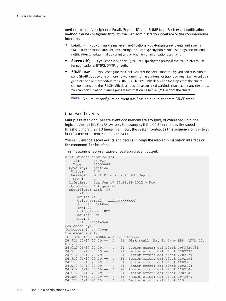
methods to notify recipients: Email, SupoprtIQ, and SNMP trap. Each event notificationmethod can be configured through the web administration interface or the command-lineinterface.
u Email — If you configure email event notifications, you designate recipients and specifySMTP, authorization, and security settings. You can specify batch email settings and the emailnotification template that you want to use when email notifications are sent.
u SupportIQ — If you enable SupportIQ, you can specify the protocol that you prefer to usefor notifications: HTTPS, SMTP, or both.
u SNMP trap — If you configure the OneFS cluster for SNMP monitoring, you select events tosend SNMP traps to one or more network monitoring stations, or trap receivers. Each event cangenerate one or more SNMP traps. The ISILON-TRAP-MIB describes the traps that the clustercan generate, and the ISILON-MIB describes the associated varbinds that accompany the traps.You can download both management information base files (MIBs) from the cluster.
You must configure an event notification rule to generate SNMP traps.
Coalesced eventsMultiple related or duplicate event occurrences are grouped, or coalesced, into onelogical event by the OneFS system. For example, if the CPU fan crosses the speedthreshold more than 10 times in an hour, the system coalesces this sequence of identicalbut discrete occurrences into one event.
You can view coalesced events and details through the web administration interface orthe command-line interface.
This message is representative of coalesced event output.
# isi events show 24.924 ID: 24.924 Type: 199990001 Severity: critical Value: 0.0 Message: Disk Errors detected (Bay 1) Node: 21 Lifetime: Sun Jun 17 23:29:29 2012 - Now Quieted: Not quieted Specifiers: disk: 35 val: 0.0 devid: 24 drive_serial: 'XXXXXXXXXXXXX' lba: 1953520064L lnn: 21 drive_type: 'HDD' device: 'da1' bay: 1 unit: 805306368Coalesced by: --Coalescer Type: GroupCoalesced events:ID STARTED ENDED SEV LNN MESSAGE24.911 06/17 23:29 -- I 21 Disk stall: Bay 1, Type HDD, LNUM 35. Disk ...24.912 06/17 23:29 -- I 21 Sector error: da1 block 195352006424.913 06/17 23:29 -- I 21 Sector error: da1 block 220223224.914 06/17 23:29 -- I 21 Sector error: da1 block 220212024.915 06/17 23:29 -- I 21 Sector error: da1 block 220210424.916 06/17 23:29 -- I 21 Sector error: da1 block 220261624.917 06/17 23:29 -- I 21 Sector error: da1 block 220216824.918 06/17 23:29 -- I 21 Sector error: da1 block 220210624.919 06/17 23:29 -- I 21 Sector error: da1 block 220210524.920 06/17 23:29 -- I 21 Sector error: da1 block 104867024.921 06/17 23:29 -- I 21 Sector error: da1 block 223
Cluster administration
192 OneFS 7.0 Administration Guide

24.922 06/17 23:29 -- C 21 Disk Repair Initiated: Bay 1, Type HDD, LNUM...
This message is representative output for coalesced duplicated events.
# isi events show 1.3035 ID: 1.3035 Type: 500010001Severity: info Value: 0.0 Message: SmartQuotas threshold violation on quota violated, domain direc... Node: All Lifetime: Thu Jun 14 01:00:00 2012 - Now Quieted: Not quieted Specifiers: enforcement: 'advisory' domain: 'directory /ifs/quotas' name: 'violated' val: 0.0 devid: 0 lnn: 0Coalesced by: --Coalescer Type: DuplicateCoalesced events:ID STARTED ENDED SEV LNN MESSAGE18.621 06/14 01:00 -- I All SmartQuotas threshold violation on quota vio...18.630 06/15 01:00 -- I All SmartQuotas threshold violation on quota vio...18.638 06/16 01:00 -- I All SmartQuotas threshold violation on quota vio...18.647 06/17 01:00 -- I All SmartQuotas threshold violation on quota vio...18.655 06/18 01:00 -- I All SmartQuotas threshold violation on quota vio...
Quieting, unquieting, and canceling eventsYou can change event state by quieting, unquieting, or canceling an event.
The following information describes the actions that you can select to change the state ofan event and the result of the selection:
u Quiet — Acknowledges an event, which removes it from list of new events and adds it to thelist of quieted events.
If a new event of the same event type is triggered, it is a separate new eventand must be quieted.
u Unquiet — Returns a quieted event to an unacknowledged state in the list of new eventsand removes it from the list of quieted events.
u Cancel — Permanently ends an occurrence of an event. Events are canceled, or ended, inone of two ways: The system cancels an event when conditions are met that end its duration,which is bounded by a start time and an end time, or you cancel an event manually.
Most events are canceled automatically by the system when they reach the end of theirduration. They remain in the system until you manually acknowledge, or quiet them,however. You can acknowledge events through either the web administration interface orthe command-line interface. For information about managing events through thecommand-line interface, see the OneFS Command Reference.
Cluster administration
Events and notifications 193

Responding to eventsYou can view event details and respond to cluster events through the web administrationinterface or the command-line interface. In the web administration interface, you canview new events on a cluster.
You can view and manage new events, open events, and recently ended events. You canalso view coalesced events and additional, more detailed information about specificevents, and you can quiet or cancel events.
View event details
You can view the details of an event and you can add a new notification rule or addsettings to another notification rule.
1. Click Dashboard > Events > Summary.The New Events page appears and displays a list of all new events.
2. In the Actions column of an event whose details you want to view, click View details.The Event Details page appears and displays additional information about the event.
3. Optional: To acknowledge the event, click Quiet Event.
4. Optional: To create a new event notification rule or to add the event settings of thisevent to an existing event notification rule, click Create Notification Rule.l To add a new notification rule for this event, in the Create Rule area, select Create a
new notification rule for event, click Submit, and then specify the settings for the rule.
l To add the settings of this event to an existing event notification rule, in the CreateRule area, select Add to an existing notification rule, select the existing eventnotification rule from the list, and then click Submit.
View the event history
You can view all events in a chronological list and view additional information about aselected event.
1. Click Dashboard > Events > Events History.The Events History page appears and displays a list of all events in chronologicalorder—newest to oldest—that have occurred on your OneFS cluster.
2. Scroll down and navigate to subsequent pages to view the events in chronologicalorder.
Manage an event
You can change the status of an event by quieting, unquieting, or canceling it.
1. Click Dashboard > Events > Summary.The New Events page appears and displays a list of all new, or unquieted, events.
2. Perform the following actions as needed.l To view additional information about an event, in the Actions column for that
event, click View details.
l To acknowledge an event, click Quiet.
l To restore an event to an unacknowledged state, click Unquiet.
l To permanently remove an occurrence of an event, click Cancel.
Cluster administration
194 OneFS 7.0 Administration Guide

Managing event notification rulesYou can modify or delete notification rules, configure event notification settings, andconfigure batch notification settings through the web administration interface or thecommand-line interface.
You can specify event notification settings, and you can create, modify, or delete eventnotification rules. You can configure the setting for how notifications are received,individually or in a batch.
Send a test event notification
You can generate a test event notification to confirm that event notifications are workingas you intend.
1. Click Dashboard > Events > Notification Settings.The Cluster Events page appears and displays email and SupportIQ settings andcontact information.
2. In the Send Test Event area, click Send test event.
3. On the Cluster Events page, click Summary to verify whether the test event wassuccessful.A corresponding test event notification appears in the New Events list, which appearsin the Message column as a message similar to Test event sent from WebUI.
View event notification rules
You can view a list of event notification rules and details about specific rules.
1. Click Dashboard > Events > Event Notification Rules.The Cluster Events page appears and displays a list of all event notification rules.
2. In the Actions column of the rule whose settings you want to view, click Edit.
3. When you have finished viewing the rule details, click Cancel.
Modify an event notification rule
You can modify event notification rules that you created. System event notification rulescannot be modified.
1. Click Dashboard > Events > Event Notification Rules.The Cluster Events page appears.
2. In the Actions column for the rule that you want to modify, click Edit.The Edit Notification Rule page appears.
3. Modify the event notification rule settings as needed.
4. Click Submit.
Delete an event notification rule
You can delete event notification rules that you created, but system event notificationrules cannot be deleted.
1. Click Dashboard > Events > Event Notification Rules.The Cluster Events page appears and displays a list of event notification rules.
2. In the Notification Rules area, in the Actions column for the rule that you want to delete,click Delete.
3. Click Yes to confirm the deletion.
Cluster administration
Events and notifications 195

View event notification settings
You can view email, SupportIQ, and contact information for event notifications.
1. Click Dashboard > Events > Notification Settings.
Modify event notification settings
You can modify email, SupportIQ, and contact settings for event notifications.
1. Click Dashboard > Events > Notification Settings.
2. Click the Modify link for the setting that you want to change.
3. Click Submit.
Specify event-notification batch mode or template settings
You can choose an event-notification batch option to specify whether you want to receivenotifications individually or as an aggregate. You also can specify a custom notificationtemplate for email notifications.
Before you can select a custom notification template, you must create it and then uploadit to a directory at the same level or below /ifs; for example, /ifs/templates.
1. Click Cluster Management > General Settings > Email Settings.The General Settings page appears and displays SMTP email settings and batch andcustom template options for event notification settings.
2. In the Event Notification Settings area, select a Notification batch mode option.
3. Leave the Set custom notification template field blank to use the default notificationtemplate.
4. In the Custom notification template field, select the custom event notification template.l Click Browse, navigate to and select the template file that you want to use, and
then click OK.
l In the Set custom notification template field, type the path and file name of thetemplate file that you want to use.
5. Click Submit.
Monitoring cluster hardwareThe default Linux SNMP tools or a GUI-based SNMP tool of your choice can be used tomonitor cluster hardware.
You can enable SNMP on all OneFS nodes to remotely monitor the hardware componentsacross the cluster, including fans, hardware sensors, power supplies, and disks. Tomaintain optimal cluster health, you can enable and configure SupportIQ to forward allcluster events to Isilon Technical Support for analysis and resolution.
The isi batterystatus command also can be used to display the current state ofNVRAM batteries and charging systems on node hardware that supports the command.
View node hardware statusYou can view the hardware status of a node.
1. Click Dashboard > Cluster Overview > Cluster Status.
2. Optional: In the Status area, click the ID number for a node.Information about the node appears, including the chassis and drive status, nodesize, throughput, CPU usage, and client connections.
Cluster administration
196 OneFS 7.0 Administration Guide

3. In the Chassis and drive status area, click Platform.Information about the hardware appears, including status, a list of monitoredcomponents, the system partitions, and the hardware log.
SNMP monitoringYou can use SNMP to remotely monitor the OneFS cluster hardware components, such asfans, hardware sensors, power supplies, and disks. The default Linux SNMP tools or aGUI-based SNMP tool of your choice can be used for this purpose.
You can enable SNMP monitoring on individual nodes on your cluster, and you can alsomonitor cluster information from any node. Generated SNMP traps are sent to your SNMPnetwork. You can configure an event notification rule that specifies the network stationwhere you want to send SNMP traps for specific events, so that when an event occurs. thecluster send the trap to that server. OneFS supports SNMP in read-only mode. SNMP v1and v2c is the default, but you can configure settings for SNMP v3 alone or SNMP v1, v2c,and v3.
When SNMP v3 is used, OneFS requires AuthNoPriv as the default. AuthPriv is notsupported.
Elements in an SNMP hierarchy are arranged in a tree structure, similar to a directory tree.As with directories, identifiers move from general to specific as the string progresses fromleft to right. Unlike a file hierarchy, however, each element is not only named, but alsonumbered.
For example, the SNMPentity .iso.org.dod.internet.private.enterprises.isilon.oneFSss.ssLocalNodeId.0 maps to .1.3.6.1.4.1.12124.3.2.0. The part of the name that refers to theOneFS SNMP namespace is the 12124 element. Anything further to the right of thatnumber is related to OneFS-specific monitoring.
Management Information Base (MIB) documents define human-readable names formanaged objects and specify their data types and other properties. You can downloadMIBs that are created for SNMP-monitoring of a OneFS cluster from the web-administration interface or manage them using the command-line interface. MIBs arestored in /usr/local/share/snmp/mibs/ on a OneFS node. The OneFS ISILON-MIBsserve two purposes:
u Augment the information available in standard MIBs
u Provide OneFS-specific information that is unavailable in standard MIBs
ISILON-MIB is a registered enterprise MIB. OneFS clusters have two separate MIBs:
u ISILON-MIB — Defines a group of SNMP agents that respond to queries from a networkmonitoring system (NMS) called OneFS Statistics Snapshot agents. As the name implies, theseagents snapshot the state of the OneFS file system at the time that it receives a request andreports this information back to the NMS.
u ISILON-TRAP-MIB — Generates SNMP traps to send to an SNMP monitoring station whenthe circumstances occur that are defined in the trap protocol data units (PDUs).
The OneFS MIB files map the OneFS-specific object IDs with descriptions. Download orcopy MIB files to a directory where your SNMP tool can find them, such as /usr/share/snmp/mibs/ or /usr/local/share/snmp/mibs, depending on the tool that you use.
To have Net-SNMP tools read the MIBs to provide automatic name-to-OID mapping, add -m All to the command, as in the following example.
snmpwalk -v2c -c public -m All <node IP> isilon
Cluster administration
SNMP monitoring 197

If the MIB files are not in the default Net-SNMP MIB directory, you may need to specify thefull path, as in the following example. Note that all three lines are one command.
snmpwalk -m /usr/local/share/snmp/mibs/ONEFS-MIB.txt:/usr/local/share/snmp/mibs/ONEFS-SNAPSHOT-MIB.txt:/usr/local/share/snmp/mibs/ONEFS-TRAP-MIB.txt \ -v2c -C c -c public <node IP> enterprises.onefs
The examples are from running the snmpwalk command on a cluster. Your SNMPversion may require different arguments.
Configure the cluster for SNMP monitoringYou can configure your cluster to monitor hardware components using SNMP.
You can enable or disable SNMP monitoring, allow SNMP access by version, andconfigure other settings, some of which are optional. All SNMP access is read-only.
The OneFS cluster does not generate SNMP traps unless you configure an eventnotification rule to send events.
Before you beginWhen SNMP v3 is used, OneFS requires AuthNoPriv as the default. AuthPriv is notsupported.
1. Click Cluster Management > General Settings > SNMP Monitoring.The SNMP Monitoring page appears.
2. In the Service area, enable or disable SNMP monitoring.a. To disable SNMP monitoring, click Disable, and then click Submit.
SNMP monitoring is disabled on the cluster.
b. To enable SNMP monitoring, click Enable, and then continue with the followingsteps to configure your settings.
3. In the Downloads area, click Download for the MIB file that you want to download.Follow the download process that is specific to your browser. If you are using InternetExplorer as your browser, continue to the next step.
4. If you are using Internet Explorer as your browser, right-click the Download link, selectSave As from the menu, and save the file to your local drive.
You can save the text in the file format that is specific to your Net-SNMP tool.
5. Copy MIB files to a directory where your SNMP tool can find them, such as /usr/share/snmp/mibs/ or /usr/local/share/snmp/mibs, depending on the SNMPtool that you use.
To have Net-SNMP tools read the MIBs to provide automatic name-to-OID mapping,add -m All to the command, as in the following example: snmpwalk -v2c -c public-m All <node IP> isilon
6. Navigate back to the SNMP Monitoring page.
7. Configure General Settings.a. In the Settings area, configure protocol access by selecting the version that you
want.
OneFS does not support writable OIDs; therefore, no write-only community stringsetting is available.
b. In the System location field, type the system name.
This setting is the value that the node reports when responding to queries. Type aname that helps to identify the location of the node.
c. Type the contact email address in the System contact field.
Cluster administration
198 OneFS 7.0 Administration Guide

8. Optional: If you selected SNMP v1/v2 as your protocol, in the SNMP v1/v2c Settingssection, in the Read-only community field, type the community name
9. Configure SNMP v3 Settings.a. In the Read-only user field, type the SNMP v3 security name to change the name of
the user with read-only privileges.
The default read-only user is general.
The password must contain at least eight characters and must not contain anyspace characters.
b. in the SNMP v3 password field, type the new password for the read-only user to seta new SNMP v3 authentication password.
The default password is password.
c. Type the new password in the Confirm password field to confirm the new password.
10. Click Submit.
ResultsSNMP monitoring is configured for remote monitoring of the cluster hardwarecomponents.
Managing SNMP settingsSNMP can be used to monitor cluster hardware and system information. Settings can beconfigured through either the web administration interface or the command-lineinterface.
You can enable SNMP monitoring on individual nodes in the cluster, and you can monitorinformation cluster-wide from any node when you enable SNMP on each node. Whenusing SNMP on a OneFS cluster, you should use a fixed general username. A password forthe general user can be configured in the web administration interface.
You should configure a network monitoring system (NMS) to query each node directlythrough a static IP address. This approach allows you to confirm that all nodes haveexternal IP addresses and therefore respond to SNMP queries. Because the SNMP proxyis enabled by default, the SNMP implementation on each node is configuredautomatically to proxy for all other nodes in the cluster except itself. This proxyconfiguration allows the Isilon Management Information Base (MIB) and standard MIBs tobe exposed seamlessly through the use of context strings for supported SNMP versions.After you download and save the appropriate MIBs, you can configure SNMP monitoringthrough either the web administration interface or though the command-line interface.
Cluster maintenanceIsilon nodes contain components that can be replaced or upgraded in the field by trainedservice personnel.
Isilon Technical Support can assist you with replacing node components or upgradingcomponents to increase performance.
Replacing node componentsIf a node component fails, Isilon Technical Support will work with you to quickly replacethe component and return the node to a healthy status.
The following components, which are considered field replaceable units (FRUs), can bereplaced in the field by trained service personnel:u battery
u boot flash drive
Cluster administration
Cluster maintenance 199

u SATA/SAS Drive
u memory (DIMM)
u fan
u front panel
u intrusion switch
u network interface card (NIC)
u IB/NVRAM card
u SAS controller
u NVRAM battery
u power supply
If your cluster is configured to send alerts to Isilon Technical Support, you will becontacted when a component needs to be replaced. If your cluster is not configured tosend alerts to Isilon, you will need to instigate a service request on your own.
Managing cluster nodesYou can add and remove nodes from a cluster. You can also shut down or restart theentire cluster.
The following actions can be taken to manage the health and performance of a cluster:u Add a node to the cluster. Expand a cluster by adding another node.
u Remove a node from the cluster. Take a node out of the cluster.
u Shut down or restart the cluster. Shutdown or restart the cluster to performmaintenance.
Add a node to the clusterYou can add an available node to an existing cluster.
If the available node is running a different version of OneFS than the cluster, or containsdifferent patches, the node will be upgraded or downgraded to match the cluster. Thefollowing nodes have minimum OneFS version requirements, and will not join clustersthat are running a lower version of OneFS:u S200 and X200 nodes require version 6.5.2 or later.
u X400 and NL400 nodes require version 6.5.5 or later.
Before you beginFor a node to be added to a cluster, an internal IP address must be available. Before youadd new nodes, add IP addresses as necessary.
For information on how to add IP addresses, see "Managing the internal cluster network."
1. Navigate to Cluster Management > Hardware Configuration > Add Nodes.
2. In the Available Nodes table, click Add for the node you want to add to the cluster.
Remove a node from the clusterYou can remove a node from a cluster. When you remove a node, the system smartfailsthe node to ensure that data on the node is transferred to other nodes in the cluster.
Removing a storage node from a cluster deletes the data from that node. Before thesystem deletes the data, the FlexProtect job safely redistributes data across the nodesremaining in the cluster.
1. Navigate to Cluster Management > Hardware Configuration > Remove Nodes.
Cluster administration
200 OneFS 7.0 Administration Guide

2. In the Remove Node area, specify the node you want to remove.
3. Click Submit.If you remove a storage node, the Cluster Status area displays smartfail progress. Ifyou remove a non-storage accelerator node, it is immediately removed from thecluster.
Shut down or restart a clusterYou can shut down or restart an entire cluster.
1. Navigate to Cluster Management > Hardware Configuration > Shutdown & Reboot Controls.
2. In the Shut Down or Reboot This Cluster area, specify an action:
Shut down Shuts down the cluster.
Reboot Stops then restarts the cluster.
3. Click Submit.
Remote support using SupportIQWith your permission, Isilon Technical Support personnel can remotely manage yourOneFS cluster to troubleshoot an open support case. The Isilon SupportIQ module allowsIsilon Technical Support personnel to gather diagnostic data about the cluster.
Isilon Technical Support representative can use SupportIQ to run scripts that gather dataabout cluster settings and operations. The SupportIQ agent then uploads the informationto a secure Isilon FTP site so it is available for Isilon Technical Support personnel toreview. These scripts do not affect cluster services or data availability.
The SupportIQ scripts are based on the Isilon isi_gather_info log-gathering tool.For more information, see the isi_gather_info man page.
The SupportIQ module is included with the OneFS operating system and does not requirea separate license. You must enable and configure the SupportIQ module beforeSupportIQ can run scripts to gather data. The feature may have been enabled when thecluster was first set up, but you can enable or disable SupportIQ through the Isilon webadministration interface.
In addition to enabling the SupportIQ module to allow the SupportIQ agent to run scripts,you can enable remote access, which allows Isilon Technical Support personnel tomonitor cluster events and remotely manage your cluster using SSH or the webadministration interface. Remote access helps Isilon Technical Support to quickly identifyand troubleshoot cluster issues. Other diagnostic tools are available for you to use inconjunction with Isilon Technical Support to gather and upload information such aspacket capture metrics.
If you enable remote access, you must also share cluster login credentials withIsilon Technical Support personnel. Isilon Technical Support personnel remotely accessyour cluster only in the context of an open support case and only after receiving yourpermission.
Cluster administration
Remote support using SupportIQ 201
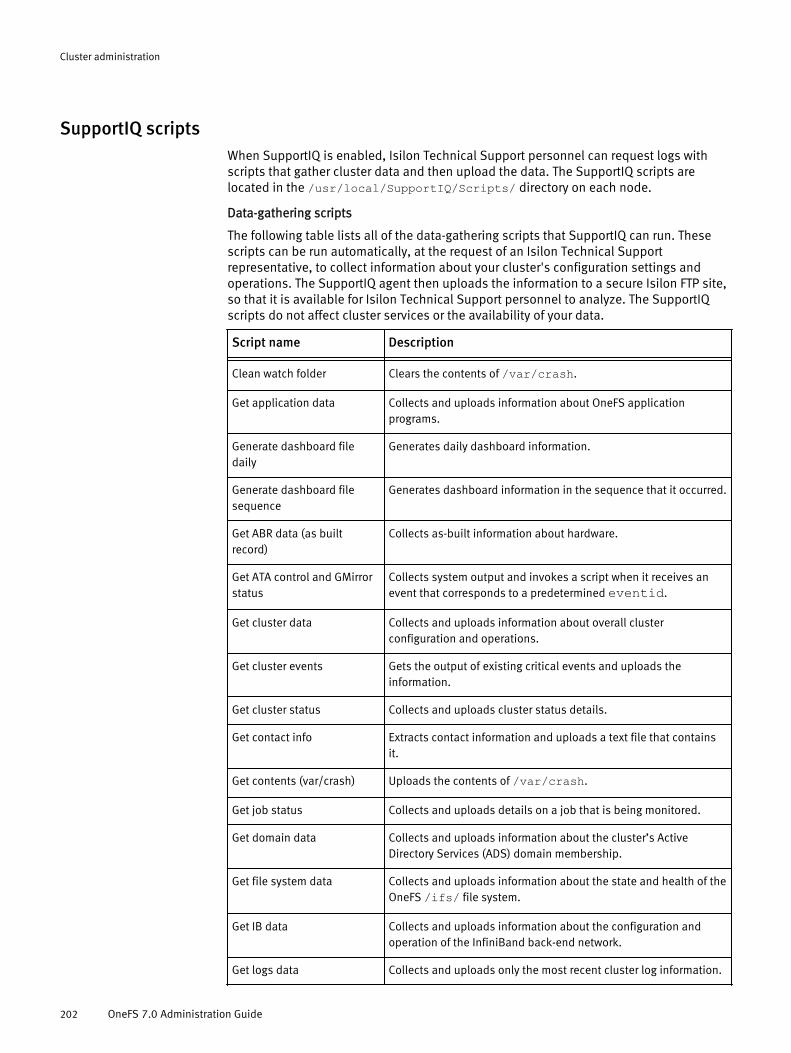
SupportIQ scriptsWhen SupportIQ is enabled, Isilon Technical Support personnel can request logs withscripts that gather cluster data and then upload the data. The SupportIQ scripts arelocated in the /usr/local/SupportIQ/Scripts/ directory on each node.
Data-gathering scripts
The following table lists all of the data-gathering scripts that SupportIQ can run. Thesescripts can be run automatically, at the request of an Isilon Technical Supportrepresentative, to collect information about your cluster's configuration settings andoperations. The SupportIQ agent then uploads the information to a secure Isilon FTP site,so that it is available for Isilon Technical Support personnel to analyze. The SupportIQscripts do not affect cluster services or the availability of your data.
Script name Description- -Clean watch folder Clears the contents of /var/crash.
Get application data Collects and uploads information about OneFS applicationprograms.
Generate dashboard filedaily
Generates daily dashboard information.
Generate dashboard filesequence
Generates dashboard information in the sequence that it occurred.
Get ABR data (as builtrecord)
Collects as-built information about hardware.
Get ATA control and GMirrorstatus
Collects system output and invokes a script when it receives anevent that corresponds to a predetermined eventid.
Get cluster data Collects and uploads information about overall clusterconfiguration and operations.
Get cluster events Gets the output of existing critical events and uploads theinformation.
Get cluster status Collects and uploads cluster status details.
Get contact info Extracts contact information and uploads a text file that containsit.
Get contents (var/crash) Uploads the contents of /var/crash.
Get job status Collects and uploads details on a job that is being monitored.
Get domain data Collects and uploads information about the cluster’s ActiveDirectory Services (ADS) domain membership.
Get file system data Collects and uploads information about the state and health of theOneFS /ifs/ file system.
Get IB data Collects and uploads information about the configuration andoperation of the InfiniBand back-end network.
Get logs data Collects and uploads only the most recent cluster log information.
Cluster administration
202 OneFS 7.0 Administration Guide

Script name Description- -Get messages Collects and uploads active /var/log/messages files.
Get network data Collects and uploads information about cluster-wide and node-specific network configuration settings and operations.
Get NFS clients Runs a command to check if nodes are being used as NFS clients.
Get node data Collects and uploads node-specific configuration, status, andoperational information.
Get protocol data Collects and uploads network status information and configurationsettings for the NFS, SMB, FTP, and HTTP protocols.
Get Pcap client stats Collects and uploads client statistics.
Get readonly status Warns if the chassis is open and uploads a text file of the eventinformation.
Get usage data Collects and uploads current and historical information aboutnode performance and resource usage.
isi_gather_info Collects and uploads all recent cluster log information.
isi_gather_info --
incremental
Collects and uploads changes to cluster log information that haveoccurred since the most recent full operation.
isi_gather_info --
incremental single node
Collects and uploads details for a single node.
Prompts you for the node number.
isi_gather_info single
node
Collects and uploads changes to cluster log information that haveoccurred since the most recent full operation.
Prompts you for the node number.
Upload the dashboard file Uploads dashboard information to the secure Isilon TechnicalSupport FTP site.
Upgrading OneFSTwo options are available for upgrading the OneFS operating system: a rolling upgrade ora simultaneous upgrade. Before upgrading the OneFS 6.0 or 6.5.x system, a pre-upgradecheck must be performed.
A rolling upgrade individually upgrades and restarts each node in the clustersequentially. During a rolling upgrade, the cluster remains online and continues servingclients with no interruption in service, although some connection resets may occur onSMB clients. Rolling upgrades are performed sequentially by node number, so a rollingupgrade takes longer to complete than a simultaneous upgrade. The final node in theupgrade process is the node that you used to start the upgrade process.
Rolling upgrades are not available for all clusters. For instructions on how toupgrade the cluster operating system, see the OneFS Release Notes.
A simultaneous upgrade installs the new operating system and restarts all nodes in thecluster at the same time. Simultaneous upgrades are faster than rolling upgrades butrequire a temporary interruption of service during the upgrade process. Your data isinaccessible during the time that it takes to complete the upgrade process.
Cluster administration
Upgrading OneFS 203

Before beginning either a simultaneous or rolling upgrade, OneFS compares the currentcluster and operating system with the new version to ensure that the cluster meetscertain criteria, such as configuration compatibility (SMB, LDAP, SmartPools), diskavailability, and the absence of critical cluster events. If upgrading puts the cluster atrisk, OneFS warns you, provides information about the risks, and prompts you to confirmwhether to continue the upgrade.
If the cluster does not meet the pre-upgrade criteria, the upgrade does not proceed, andthe unsupported statuses are listed.
Cluster join modesYou can specify the method that you want to use to join nodes to a cluster. The join modedetermines how the system responds when new OneFs nodes are added to the subnetoccupied by the OneFS cluster. You can set join modes through the web administrationinterface or the command-line interface.
Mode Description Notes- - -Manual Configures OneFS to join new
nodes to the cluster in aseparate manual process,allowing the addition of a nodewithout requiring authorization
Secure Requires authorization of everynode added to the cluster
If you use the secure joinmode, you cannot use the
serial console wizard option [2]Join an existing cluster to join
a node to the cluster. You mustadd the node from cluster byusing the web administrationinterface or the isi devices-a add -d<unconfigured_node_serial_no> command in the
command-line interface.
Event notification settingsYou can specify whether you want to receive event notifications as aggregated batches oras event notifications or receive individual notifications for each event. Batchnotifications are sent every 10 seconds.
The batch options that are described in this table affect both the content and the subjectline of notification emails that are sent in response to system events. You can specifyevent notification batch options when you configure SMTP email settings.
Setting Option Description- - -Notification batchmode
Batch all Generates a single email for each eventnotification.
Batch by severity Generates an email that containsaggregated notifications for each event of
Cluster administration
204 OneFS 7.0 Administration Guide

Setting Option Description- - -
the same severity, regardless of eventcategory.
Batch by category Generates an email an email that containsaggregated notifications for event of thesame category, regardless of severity.
No batching Generates one email per event.
Custom notificationtemplate
No custom notificationtemplate is set
Sends the email notification in the defaultOneFS notification template format.
Set custom notificationtemplate
Sends the email notifications in the formatthat you defined in your custom templatefile.
System job managementFor a cluster to run efficiently, consistent maintenance must be performed to ensure thatfile systems are properly organized. The OneFS System Job Engine schedules andexecutes this maintenance.
When performing maintenance on a clustered system, even a routine task like a virusscan has the ability to affect distributed computing performance. The System Job Engineis designed to allow for the automated execution of maintenance jobs, while constantlymonitoring and mitigating the impact of jobs on the overall performance of the cluster.
System administrators access job schedules and policies through the OneFS interface,and can tailor maintenance to the specific workflow of the cluster.
Job engine overviewThe System Job Engine breaks jobs down into smaller blocks of work, allowing the engineto react quickly to errors or cluster performance degradation even during longer jobs.
Jobs are broken down into phases, which are broken down into tasks, which are directedat items.
u Job — An application built into the System Job Engine.
u Phase — Jobs are broken down into phases. Some jobs have as little as one phase, othershave as many as seven. If an error is detected while a job is running, the job will not progresspast its current phase unless it is determined safe to do so.
u Task — Phases are broken down into tasks. A phase includes at least one task, but mayemploy several. A task is the actual action that is taken on the system.
u Item — Items are the targets of tasks, the file system components that are being operated onby a task.
The Job Engine tracks interaction between a task and its target items.u If an error is detected, the job will continue as long as the error does not affect the
overall goal of the job, otherwise the job is cancelled.
u If the task is slowing the performance of a node, the task will be asked to slow downand consume less resources.
The System Job Engine accumulates task and item results in logs that provideadministrators insight into the maintenance of a cluster.
Cluster administration
System job management 205

System jobsOneFS offers a number of jobs to assist with cluster administration and maintenance.
AutoBalanceBalances free space within the cluster. AutoBalance is most efficient in clusterscontaining only hard disk drives (HDDs).
AutoBalanceLinBalances free space within the cluster. AutoBalanceLin is most efficient in clusters wherefile system metadata is stored on solid state drives (SSDs).
AVScanPerforms an antivirus scan on all files.
CollectReclaims free space that could not be freed earlier due to a node or drive beingunavailable.
DomainMarkAssociates a path and its contents with a domain.
FlexProtectPerforms a protection pass on the file system. FlexProtect is most efficient in clusterscontaining only HDDs.
FlexProtectLinPerforms a protection pass on the file system. FlexProtectLin is most efficient in clusterswhere file system metadata is stored on SSDs.
FSAnalyzeGathers file system analytics.
IntegrityScanVerifies file system integrity.
MediaScanRemoves media-level errors from disks.
MultiScanRuns the AutoBalance and Collect jobs together.
PermissionRepairCorrects file and directory permissions in the /ifs directory.
QuotaScanUpdates quota accounting for domains created on an existing file tree.
SetProtectPlusApplies a default file policy across the cluster. This is used only if SmartPools is notlicensed.
Cluster administration
206 OneFS 7.0 Administration Guide
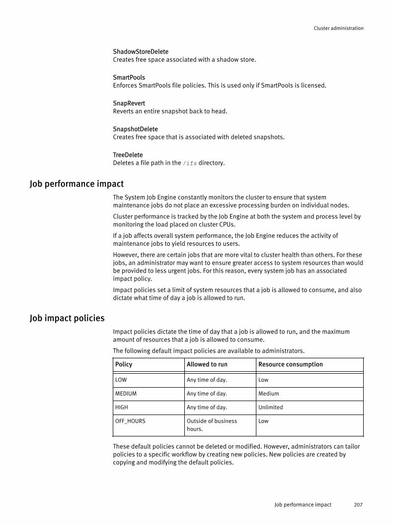
ShadowStoreDeleteCreates free space associated with a shadow store.
SmartPoolsEnforces SmartPools file policies. This is used only if SmartPools is licensed.
SnapRevertReverts an entire snapshot back to head.
SnapshotDeleteCreates free space that is associated with deleted snapshots.
TreeDeleteDeletes a file path in the /ifs directory.
Job performance impactThe System Job Engine constantly monitors the cluster to ensure that systemmaintenance jobs do not place an excessive processing burden on individual nodes.
Cluster performance is tracked by the Job Engine at both the system and process level bymonitoring the load placed on cluster CPUs.
If a job affects overall system performance, the Job Engine reduces the activity ofmaintenance jobs to yield resources to users.
However, there are certain jobs that are more vital to cluster health than others. For thesejobs, an administrator may want to ensure greater access to system resources than wouldbe provided to less urgent jobs. For this reason, every system job has an associatedimpact policy.
Impact policies set a limit of system resources that a job is allowed to consume, and alsodictate what time of day a job is allowed to run.
Job impact policiesImpact policies dictate the time of day that a job is allowed to run, and the maximumamount of resources that a job is allowed to consume.
The following default impact policies are available to administrators.
Policy Allowed to run Resource consumption- - -LOW Any time of day. Low
MEDIUM Any time of day. Medium
HIGH Any time of day. Unlimited
OFF_HOURS Outside of businesshours.
Low
These default policies cannot be deleted or modified. However, administrators can tailorpolicies to a specific workflow by creating new policies. New policies are created bycopying and modifying the default policies.
Cluster administration
Job performance impact 207

Job prioritiesEvery job in the System Job Engine is assigned a priority. Priorities determine which jobwill yield when two jobs attempt to run at the same time.
When jobs are scheduled to run at the same time, the higher priority job will run first.
The highest priority jobs have a priority of 1. Higher priority jobs will always interruptlower priority jobs.
If a low priority job is interrupted, it will be inserted back into the priority queue. Whenthe job reaches the front of the priority queue again, it will resume from where it left off.
If two jobs at the same priority level attempt to run, the job that entered the queue firstwill run.
The following list contains Priority values for each job. These priorities can be adjusted bya system administrator.
Job Priority
Autobalance 4
Autobalance Lin 4
AV Scan 6
Collect 4
SmartPools 6
MultiScan 4
Flex Protect 1
FS Analyze 6
Integrity Scan 1
Media Scan 8
Repair 5
Quota Scan 6
Set Protect Plus 6
Snapshot Delete 2
Tree Delete 4
Upgrade 3
Managing system jobsAdministrators have the ability to manually control job activity.
The following actions are available to control current job activity:u Start a job. Begin a job that is currently inactive.u Pause a job. Momentarily stop a job.u Update a job. Change the settings of a running, waiting, or paused job.
Cluster administration
208 OneFS 7.0 Administration Guide

u Resume a job. Continue a paused job.
u Cancel a job. Discontinue a job that is currently active.
u Retry a job. Restart a job that was previously interrupted by the system.
u Modify job settings. Change a job's priority level or impact policy.
Start a jobYou can start a job manually at any time.
1. Navigate to Cluster Management > Operations > Operations Summary.
2. In the Running Jobs area, clickStart job.
3. From the Job list, select the job that you want to run.
4. From the Priority list, select the priority level for the job.
If no priority is selected, the job runs at its default priority.
5. From the Impact policy list, select the impact policy for the job.
If no impact policy is selected, the job runs with the default impact policy for that jobtype.
6. Click Start.The job displays in the Running Jobs table.
Pause a jobYou can pause an in-progress job. Pausing a job allows you to temporarily free clusterresources without losing progress made by the job.
1. Navigate to Cluster Management > Operations > Operations Summary.
2. In the Policies table, click Pause for the job you want to pause.The job moves from the Running Jobs table to the Paused and Waiting Jobs table.
3. In the Paused and Waiting Jobs table, click Resume for the job you want to resume.The job moves from the Paused and Waiting Jobs table to the Running Jobs table.
Update a jobYou can change the priority and impact policy of a running, waiting, or paused job.
1. Navigate to Cluster Management > Operations > Operations Summary.
2. In the Running Jobs or Paused and Waiting Jobs table, click Update for the job you want toupdate.
3. Adjust the priority of the job by selecting a new priority from the Priority list.
4. Adjust the default impact policy of the job by selecting a new impact policy from theImpact policy list.
5. Click Update to save the new settings.If you update a running job, the job will automatically resume. If you update a pausedor waiting job, the job will return to that status.
ResultsOnly the current instance of the job will run with the updated settings. The next instanceof the job will return to the default settings for that job. To permanently modify jobsettings, click on a job name, then click Modify job defaults in the Job Details area.
Cluster administration
Managing system jobs 209
Resume a jobYou can resume a paused job. The job will continue from the phase in which it waspaused.
1. Navigate to Cluster Management > Operations > Operations Summary.
2. In the Paused and Waiting Jobs table, click Resume for the job you want to continue.
The job displays in the Running Jobs table.
Cancel a jobYou can discontinue a running, paused, or waiting job.
1. Navigate to Cluster Management > Operations > Operations Summary.
2. In the Running Jobs table, click Cancel for the job you want to cancel.
This action can also be performed on a job in the Paused and Waiting Jobs table.
The job displays in the Recent Job History table as User Cancelled.
Retry a jobIf a job fails, you can manually restart the job without waiting for the next scheduled runtime.
1. Navigate to Cluster Management > Operations > Operations Summary.
2. In the Failed Jobs table, click Retry for the job you want to run again.The job moves from the Failed Jobs table to the Running Jobs table.
Modify job settingsYou can modify the default priority level, impact level, and schedule of a job.
1. Navigate to Cluster Management > Operations > Jobs and Impact Policies.
2. In the Jobs table, click the name of the job you want to modify.Information related to the job displays, including the current default settings,schedule, current state, and recent activity.
3. In the Job Details area, click Modify job defaults.
4. Adjust the default priority of the job by selecting a new priority from the Default prioritylist.
5. Adjust the default impact policy of the job by selecting a new impact policy from theDefault impact policy list.
6. Adjust the schedule of the job by clicking Edit schedule.a. In the Interval area, click Daily, Weekly, Monthly, or Yearly to set the frequency that
the job runs.When you click an option, the right side of the Interval area will update withadditional scheduling options. Select the exact day or days you want the job torun.
b. In the Frequency area, click Once or Multiple times to set the number of times thejob will run on the day specified in the previous step.When you click an option, the right side of the Frequency area will update withadditional scheduling options. Select the exact time or times of day you want thejob to run.
c. Click Done.The Schedule line displays the new schedule.
Cluster administration
210 OneFS 7.0 Administration Guide

7. Click SubmitThe modified settings display in the Jobs table.
Monitoring system jobsAdministrators have the ability to monitor jobs that are currently running, and review theresults of completed jobs.
The following actions are available for viewing job activity:u View active jobs. See a list of jobs that are currently running.
u View job history. See the recent activity of a specific job.
View active jobsYou can view the system jobs that are currently running on your cluster.
1. Navigate to Cluster Management > Operations > Operations Summary.
2. Locate the Running Jobs table.All currently active jobs display in the Running Jobs table, along with job settings andprogress details.
View job historyYou can view recent job engine activity for all jobs, or for a specific job.
1. Navigate to Cluster Management > Operations > Operations Summary.
2. Locate the Recent Job History table.The table displays a chronological list of the last ten job events occurring on thecluster. Event information includes the time the event occurred, the job responsiblefor the event, and results related to the event.
3. View recent events beyond the last ten by clicking View full job history.
4. Click on a job name to recent events for that job only.
Recent events for the job are listed in the Job Events table.
Creating impact policiesAdministrators have the ability to create impact policies that fit the specific needs of theirworkflow.
The following actions are available when working with impact policies:u Create an impact policy. Create and configure a new impact policy.
u Copy an impact policy. Use an existing impact policy as the foundation for a newpolicy.
Create an impact policyYou can create and configure new impact policies for use by scheduled jobs.
1. Navigate to Cluster Management > Operations > Jobs and Impact Policies.
2. In the Impact Policies area, click Add impact policy.The Policy Details area will display.
3. In the Name field, type the name of the new impact policy. The name value must beless than 64 characters.
4. Optional: In the Description field, type an optional overview of the new impact policy.The description must be less than 1024 characters.
Cluster administration
Monitoring system jobs 211

Include information specific to the impact policy such as unique scheduleparameters, or logistical requirements that make the new impact policy necessary.
5. Click Submit.
6. In the Impact Schedule area, modify the schedule of the impact policy by adding,editing, or deleting impact intervals.
The default impact schedule for a new policy is to run at any time with an impactsetting of Low.
7. In the Policy Details area, click Submit.The new impact policy appears in the Impact Policies table, and is now available toassign to jobs.
Copy an impact policyYou can use an existing impact policy as the template for a new policy by making a copyof a policy, then editing the copy.
1. Navigate to Cluster Management > Operations > Jobs and Impact Policies.
2. In the Impact Policies table, click Copy for the policy you want to use to create yournew policy.The copy appears directly below the original in the Impact Policies table, with _1added to the original name.
3. Click Edit for the copy you want to modify.
4. Modify one or all of the following:
Policy name a. In the Policy field, type in a new name for the policy.
b. Click Submit.
Policy description a. In the Description field, type an overview for the new impactpolicy.
b. Click Submit.
Impact schedule a. In the Impact Schedule area, modify the schedule of the newimpact policy by adding, editing, or deleting impactintervals .
Managing impact policiesAdministrators have the ability to tailor existing impact policies to fit their workflow.
The following actions are available when working with impact policies:u Modify an impact policy. Adjust the impact profile of a policy by changing its resource
allocation or schedule.
u Delete an impact policy. Remove an impact policy from the System Job Engine.
u Modify the impact schedule of a policy. Establish a period of time where specificimpact limitations are placed on a job. For example, a job will run with low impactduring business hours, but run with high impact during non-business hours.
u View impact policy settings. Open a full list of the available impact policies to reviewcurrent settings.
Cluster administration
212 OneFS 7.0 Administration Guide
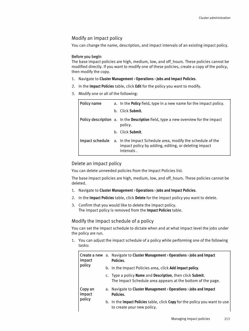
Modify an impact policyYou can change the name, description, and impact intervals of an existing impact policy.
Before you beginThe base impact policies are high, medium, low, and off_hours. These policies cannot bemodified directly. If you want to modify one of these policies, create a copy of the policy,then modify the copy.
1. Navigate to Cluster Management > Operations > Jobs and Impact Policies.
2. In the Impact Policies table, click Edit for the policy you want to modify.
3. Modify one or all of the following:
Policy name a. In the Policy field, type in a new name for the impact policy.
b. Click Submit.
Policy description a. In the Description field, type a new overview for the impactpolicy.
b. Click Submit.
Impact schedule a. In the Impact Schedule area, modify the schedule of theimpact policy by adding, editing, or deleting impactintervals .
Delete an impact policyYou can delete unneeded policies from the Impact Policies list.
The base impact policies are high, medium, low, and off_hours. These policies cannot bedeleted.
1. Navigate to Cluster Management > Operations > Jobs and Impact Policies.
2. In the Impact Policies table, click Delete for the impact policy you want to delete.
3. Confirm that you would like to delete the impact policy.The impact policy is removed from the Impact Policies table.
Modify the impact schedule of a policyYou can set the impact schedule to dictate when and at what impact level the jobs underthe policy are run.
1. You can adjust the impact schedule of a policy while performing one of the followingtasks:
Create a newimpactpolicy
a. Navigate to Cluster Management > Operations > Jobs and ImpactPolicies.
b. In the Impact Policies area, click Add impact policy.
c. Type a policy Name and Description, then click Submit.The Impact Schedule area appears at the bottom of the page.
Copy animpactpolicy
a. Navigate to Cluster Management > Operations > Jobs and ImpactPolicies.
b. In the Impact Policies table, click Copy for the policy you want to useto create your new policy.
Cluster administration
Managing impact policies 213

c. Click Edit for the copy you want to modify.The Impact Schedule area appears at the bottom of the page.
Modify animpactpolicy
a. Navigate to Cluster Management > Operations > Jobs and ImpactPolicies.
b. In the Impact Policies table, click Edit for the policy you want tomodify.The Impact Schedule area appears at the bottom of the page.
The Impact Schedule area displays the schedule for the policy in a table. Every row inthe table contains an impact interval. An impact interval is a window of time wherethe impact level of a job is raised or lowered, or the job is paused.
2. You can modify the impact schedule of a policy by performing the following actions:
Add animpactinterval
a. Click Add impact interval.
b. From the Impact list, select the impact level for the new interval.
c. Specify the day and time to begin the impact interval.
d. Specify the day and time to end the impact interval.
e. Click Submit.The new impact interval appears as part of the impact schedulefor the policy.
Create additional impact intervals as necessary. New impactintervals will overwrite existing intervals.
Modify animpactinterval
a. In the Impact Interval table, click Edit for the interval you want tomodify.
b. Adjust the impact level, start time, or end time.
c. Click Submit.The modified impact interval appears as part of the impactschedule for the policy.
Delete animpactinterval
a. In the Impact Interval table, click Delete for the interval you want todelete.
b. Confirm that you would like to delete the impact interval.The impact interval is removed from the impact schedule for thepolicy.
View impact policy settingsYou can view the impact policy settings for any job.
1. Navigate to Cluster Management > Operations > Jobs and Impact Policies.
2. In the Jobs table, click the name of the job you would like to view.
3. In the Job Details area, locate the following impact policy settings:
Default impact policy The impact policy that the job uses.
Schedule The impact schedule that the job uses.
Cluster administration
214 OneFS 7.0 Administration Guide

CHAPTER 11
SmartQuotas
The SmartQuotas module is an optional quota-management tool that monitors andenforces administrator-defined storage limits. Using accounting and enforcement quotalimits, reporting capabilities, and automated notifications, SmartQuotas managesstorage use, monitors disk storage, and issues alerts when disk-storage limits areexceeded.
Quotas help you manage storage usage according to criteria that you define. Quotas areused as a method of tracking—and sometimes limiting—the amount of storage that auser, group, or project consumes. Quotas are a useful way of ensuring that a user ordepartment does not infringe on the storage that is allocated to other users ordepartments. In some quota implementations, writes beyond the defined space aredenied, and in other cases, a simple notification is sent.
The SmartQuotas module requires a separate license. For additional information aboutthe SmartQuotas module or to activate the module, contact your EMC Isilon salesrepresentative.
u Quotas overview.................................................................................................216u Creating quotas...................................................................................................222u Managing quotas................................................................................................223u Managing quota notifications..............................................................................226u Managing quota reports......................................................................................229u Basic quota settings............................................................................................230u Advisory limit quota notification rules settings....................................................231u Soft limit quota notification rules settings...........................................................232u Hard limit quota notification rules settings..........................................................233u Limit notification settings....................................................................................233u Quota report settings..........................................................................................234u Custom email notification template variable descriptions...................................235
SmartQuotas 215
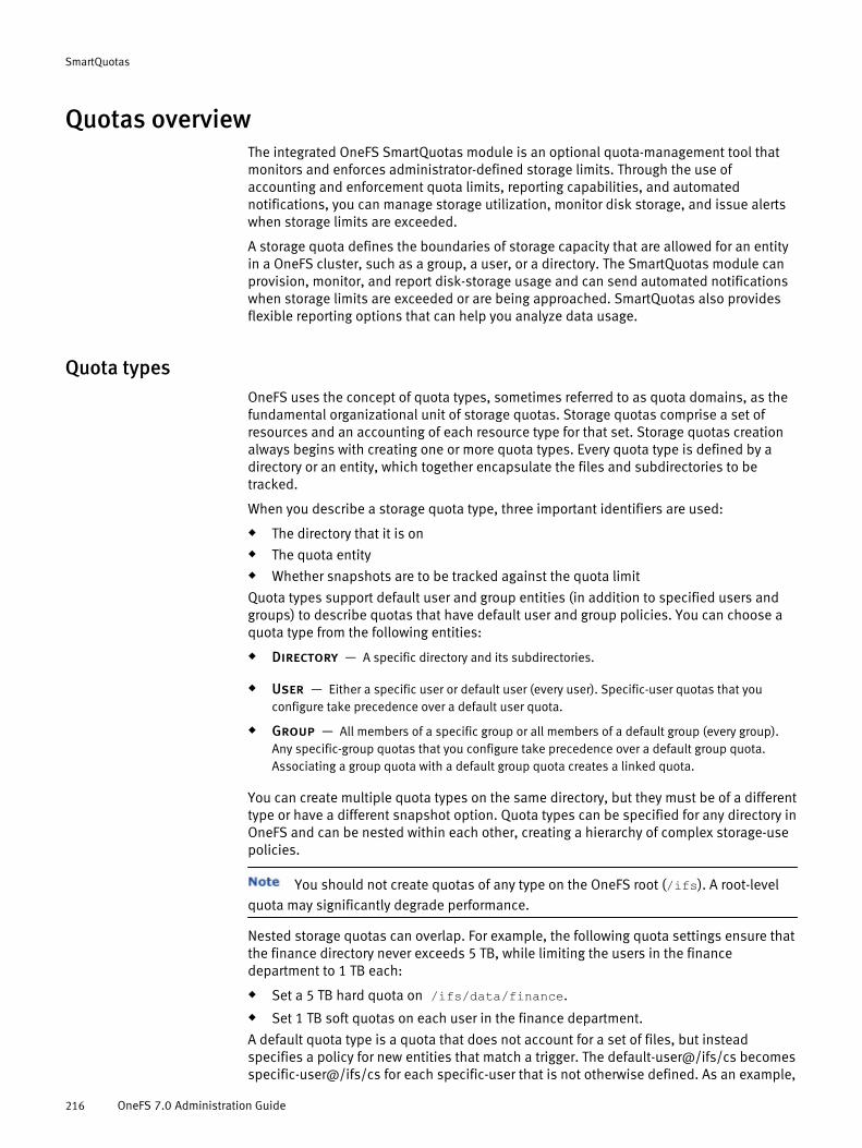
Quotas overviewThe integrated OneFS SmartQuotas module is an optional quota-management tool thatmonitors and enforces administrator-defined storage limits. Through the use ofaccounting and enforcement quota limits, reporting capabilities, and automatednotifications, you can manage storage utilization, monitor disk storage, and issue alertswhen storage limits are exceeded.
A storage quota defines the boundaries of storage capacity that are allowed for an entityin a OneFS cluster, such as a group, a user, or a directory. The SmartQuotas module canprovision, monitor, and report disk-storage usage and can send automated notificationswhen storage limits are exceeded or are being approached. SmartQuotas also providesflexible reporting options that can help you analyze data usage.
Quota typesOneFS uses the concept of quota types, sometimes referred to as quota domains, as thefundamental organizational unit of storage quotas. Storage quotas comprise a set ofresources and an accounting of each resource type for that set. Storage quotas creationalways begins with creating one or more quota types. Every quota type is defined by adirectory or an entity, which together encapsulate the files and subdirectories to betracked.
When you describe a storage quota type, three important identifiers are used:
u The directory that it is onu The quota entityu Whether snapshots are to be tracked against the quota limit
Quota types support default user and group entities (in addition to specified users andgroups) to describe quotas that have default user and group policies. You can choose aquota type from the following entities:
u Directory — A specific directory and its subdirectories.
u User — Either a specific user or default user (every user). Specific-user quotas that youconfigure take precedence over a default user quota.
u Group — All members of a specific group or all members of a default group (every group).Any specific-group quotas that you configure take precedence over a default group quota.Associating a group quota with a default group quota creates a linked quota.
You can create multiple quota types on the same directory, but they must be of a differenttype or have a different snapshot option. Quota types can be specified for any directory inOneFS and can be nested within each other, creating a hierarchy of complex storage-usepolicies.
You should not create quotas of any type on the OneFS root (/ifs). A root-levelquota may significantly degrade performance.
Nested storage quotas can overlap. For example, the following quota settings ensure thatthe finance directory never exceeds 5 TB, while limiting the users in the financedepartment to 1 TB each:
u Set a 5 TB hard quota on /ifs/data/finance.u Set 1 TB soft quotas on each user in the finance department.
A default quota type is a quota that does not account for a set of files, but insteadspecifies a policy for new entities that match a trigger. The default-user@/ifs/cs becomesspecific-user@/ifs/cs for each specific-user that is not otherwise defined. As an example,
SmartQuotas
216 OneFS 7.0 Administration Guide

you can create a default-user quota on the /ifs/dir-1 directory, where that directory isowned by the root user. The default-user type automatically creates a new domain on thatdirectory for root and adds the usage there:
my-OneFS-1# mkdir /ifs/dir-1my-OneFS-1# isi quota quotas create --default-user --path=/ifs/dir-1my-OneFS-1# isi quota quotas ls -v --path=/ifs/dir-1Type Path Policy Snap Usage -------------------- ---------------------- ----------- ----- -------- default-user /ifs/dir-1 enforcement no 0B [usage-with-no-overhead] ( 0B) [usage-with-overhead] ( 0B) [usage-inode-count] (0)* user:root /ifs/dir-1 enforcement no 0B [usage-with-no-overhead] ( 0B) [usage-with-overhead] ( 2.0K) [usage-inode-count] (1)
Now add a file that is owned by a different user (admin).
my-OneFS-1# touch /ifs/dir-1/somefilemy-OneFS-1# chown admin /ifs/dir-1/somefilemy-OneFS-1# isi quota quotas ls -v --path=/ifs/dir-1Type Path Policy Snap Usage -------------------- ---------------------- ----------- ----- -------- default-user /ifs/dir-1 enforcement no 0B [usage-with-no-overhead] ( 0B) [usage-with-overhead] ( 0B) [usage-inode-count] (0)* user:root /ifs/dir-1 enforcement no 18B [usage-with-no-overhead] ( 18B) [usage-with-overhead] ( 2.0K) [usage-inode-count] (1)* user:admin /ifs/dir-1 enforcement no 0B [usage-with-no-overhead] ( 0B) [usage-with-overhead] ( 1.5K) [usage-inode-count] (1)
In this example, the default-user type created a new specific-user type automatically(user:admin) and added the new usage to it. Default-user does not have any usagebecause it is used only to generate new quotas automatically. Default-user enforcementis copied to a specific-user (user:admin), and the inherited quota is called a linked quota.In this way, each user account gets its own usage accounting.
Defaults can overlap; for example, default-user@/ifs and default-user@/ifs/cs both maybe defined. If default enforcement changes, OneFS storage quotas propagate thechanges to the linked quotas asynchronously. Because the update is asynchronous,there is some lag before updates are in effect. If a default type (every user or every group)is deleted, OneFS deletes all children that are marked as inherited. As an option, you candelete the default without deleting the children, but it is important to note that this actionbreaks inheritance on all inherited children.
Continuing with the example, add another file that is owned by the root user. Because theroot type exists, the new usage is added to it.
my-OneFS-1# touch /ifs/dir-1/anotherfilemy-OneFS-1# isi quota ls -v --path=/ifs/dir-1Type Path Policy Snap Usage -------------------- ---------------------- ----------- ----- -------- default-user /ifs/dir-1 enforcement no 0B [usage-with-no-overhead] ( 0B) [usage-with-overhead] ( 0B) [usage-inode-count] (0)* user:root /ifs/dir-1 enforcement no 39B [usage-with-no-overhead] ( 39B) [usage-with-overhead] ( 3.5K) [usage-inode-count] (2)* user:admin /ifs/dir-1 enforcement no 0B
SmartQuotas
Quota types 217

[usage-with-no-overhead] ( 0B) [usage-with-overhead] ( 1.5K) [usage-inode-count] (1)
The enforcement on default-user is copied to the specific-user when the specific-userallocates within the type, and the new inherited quota type is also a linked quota.
Configuration changes for linked quotas must be made on the parent (default)quota that the linked quota is inheriting from. Changes to the parent quota arepropagated to all children. If you want to override configuration from the parent quota,you must unlink the quota first.
Usage accounting and limitsStorage quotas support two usage types—enforcement limits and accounting—that youcan create to manage storage space.
OneFS quotas can be configured by usage type to track or limit storage use. Theaccounting option, which monitors disk-storage use, is useful for auditing, planning, andbilling. Enforcement limits set storage limits for users, groups, or directories.
u Accounting — The accounting option tracks but does not limit disk-storage use. Using theaccounting option for a quota, you can monitor inode count and physical and logical spaceresources. Physical space refers to all of the space used to store files and directories, includingdata and metadata in the domain. Logical space refers to the sum of all files sizes, excludingfile metadata and sparse regions. User data storage is tracked using logical-space calculations,which do not include protection overhead. As an example, by using the accounting option, youcan do the following:u Track the amount of disk space used by various users or groups to bill each entity for only
the disk space used.
u Review and analyze reports that help you identify storage usage patterns, which you canuse to define storage policies for the organization and educate users of the file systemabout using storage more efficiently.
u Plan for capacity and other storage needs.
u Enforcement limits — Enforcement limits include all of the functionality of the accountingoption, plus the ability to limit disk storage and send notifications. Using enforcement limits,you can logically partition a cluster to control or restrict how much storage that a user, group,or directory can use. For example, you can set hard- or soft-capacity limits to ensure thatadequate space is always available for key projects and critical applications and to ensure thatusers of the cluster do not exceed their allotted storage capacity. Optionally, you can deliverreal-time email quota notifications to users, group managers, or administrators when they areapproaching or have exceeded a quota limit.
If a quota type uses the accounting-only option, enforcement limits cannot beused for that quota.
The actions of an administrator logged in as root may push a domain over a quotathreshold. For example, changing the protection level or taking a snapshot has thepotential to exceed quota parameters. System actions such as repairs also may push aquota domain over the limit.
There are three types of administrator-defined enforcement thresholds.
SmartQuotas
218 OneFS 7.0 Administration Guide

Threshold type Description- -Hard Limits disk usage to a size that cannot be
exceeded. If an operation, such as a file write,causes a quota target to exceed a hard quota,the following events occur:
l the operation fails
l an alert is logged to the cluster
l a notification is issued to specifiedrecipients.
Writes resume when the usage falls below thethreshold.
Soft Allows a limit with a grace period that can beexceeded until the grace period expires. Whena soft quota is exceeded, an alert is logged tothe cluster and a notification is issued tospecified recipients; however, data writes arepermitted during the grace period.
If the soft threshold is still exceeded when thegrace period expires, data writes fail, and ahard-limit notification is issued to therecipients you have specified.
Writes resume when the usage falls below thethreshold.
Advisory An informational limit that can be exceeded.When an advisory quota threshold is exceeded,an alert is logged to the cluster and anotification is issued to specified recipients.Advisory thresholds do not prevent data writes.
Disk-usage calculationsFor each quota that you configure, you can specify whether data-protection overhead isincluded in future disk-usage calculations. Overhead settings should be configuredcarefully, because they can significantly affect the amount of disk space that is availableto users.
Typically, most quota configurations do not need to include overhead calculations. If youinclude data-protection overhead in usage calculations for a quota, future disk-usagecalculations for the quota include the total amount of space that is required to store filesand directories, in addition to any space that is required to accommodate your data-protection settings, such as parity or mirroring. For example, consider a user who isrestricted by a 40 GB quota that includes data-protection overhead in its disk-usagecalculations. If your cluster is configured with a 2x data-protection level (mirrored) andthe user writes a 10 GB file to the cluster, that file actually consumes 20 GB of space: 10GB for the file and 10 GB for the data-protection overhead. In this example, the user hasreached 50 percent of the 40 GB quota by writing a 10 GB file to the cluster.
You can configure quotas to include the space that is consumed by snapshots. A singlepath can have two quotas applied to it: one without snapshot usage (default) and onewith snapshot usage. If snapshots are included in the quota, more files are included in
SmartQuotas
Disk-usage calculations 219

the calculation than are in the current directory. The actual disk usage is the sum of thecurrent directory and any snapshots of that directory. You can see which snapshots areincluded in the calculation by examining the .snapshot directory for the quota path.
Older snapshots are not added retroactively to usage when you create a newquota. Only those snapshots created after the QuotaScan job finishes are included in thecalculation.
If you do not include data-protection overhead in usage calculations for a quota, futuredisk-usage calculations for the quota include only the space that is required to store filesand directories. Space that is required for the cluster's data-protection setting is notincluded. Consider the same example user, who is now restricted by a 40 GB quota thatdoes not include data-protection overhead in its disk-usage calculations. If your cluster isconfigured with a 2x data-protection level and the user writes a 10 GB file to the cluster,that file consumes only 10 GB of space: 10 GB for the file and no space for the data-protection overhead. In this example, the user has reached 25 percent of the 40 GB quotaby writing a 10 GB file to the cluster. This method of disk-usage calculation is typicallyrecommended for most quota configurations.
Clones and cloned files are accounted for by quotas as though they consumeboth shared and unshared data: a clone and a copy of the same file do not consumedifferent amounts of data. If the quota includes data protection overhead, however, thedata protection overhead for shared data is not included in the usage calculation.
Quota notificationsStorage quota notifications, which are generated as a part of enforcement quotas,provide users with information about threshold violations when a violation conditionoccurs and while the violation condition persists. Each notification rule defines thecondition that is to be enforced and the action that is to be executed when the conditionis true. An enforcement quota can define multiple notification rules.
Quota notifications are generated on quota domains with enforcement quota thresholdsthat you define. When thresholds are exceeded, automatic email notifications can besent to specified users, or you can monitor notifications as system alerts or receiveemails for these events.
Notifications can be configured globally, to apply to all quota domains, or be configuredfor specific quota domains.
Enforcement quotas support the following notification settings. A given quota can useonly one of these settings.
Limit notification settings Description- -Turn Off Notifications for this Quota Disables all notifications for the quota.
Use Default Notification Rules Uses the global default notification for thespecified type of quota.
Use Custom Notification Rules Enables the creation of advanced, customnotifications that apply to the specific quota.Custom notifications can be configured for anyor all of the threshold types (hard, soft, oradvisory) for the specified quota.
SmartQuotas
220 OneFS 7.0 Administration Guide

Quota notification rules can be written to trigger an action according to event thresholds(a notification condition). A rule can specify a schedule, such as "every day at 1:00 AM,"for executing an action or immediate notification of certain state transitions. When anevent occurs, a notification trigger executes one or more specified actions, such assending an email to a user or administrator or pushing a cluster alert to the interface.Examples of notification conditions include the following:
u "Notify when a threshold is exceeded; at most, once every 5 minutes"
u "Notify when allocation is denied; at most, once an hour"
u "Notify while over threshold, daily at 2 AM"
u "Notify while grace period expired weekly, on Sundays at 2 AM"
Notifications are triggered for events grouped by the following categories:
u Instant notifications — Includes the write-denied notification, triggered when a hardthreshold denies a write, and the threshold-exceeded notification, triggered at the moment ahard, soft, or advisory threshold is exceeded. These are one-time notifications because theyrepresent a discrete event in time.
u Ongoing notifications — Generated on a scheduled basis to indicate a persistingcondition, such as a hard, soft, or advisory threshold being over a limit or a soft threshold'sgrace period being expired for a prolonged period.
Quota notification rulesYou can write quota notification rules that are triggered by event thresholds.
The following examples demonstrate the types of criteria that can be used to configurenotification rules.
u "Notify when a threshold is exceeded; at most, once every 5 minutes"
u "Notify when allocation is denied; at most, once an hour"
u "Notify while over threshold, daily at 2 AM"
u "Notify while grace period expired weekly, on Sundays at 2 AM"
When an event occurs, a notification is triggered according to your notification rule. Forexample, you can create a notification rule that sends an email to a user or administratorwhen a disk-space allocation threshold is exceeded by a group.
Quota reportsThe OneFS SmartQuotas module provides reporting options that enable administrators tomore effectively manage cluster resources and analyze usage statistics.
Storage quota reports provide a summarized view of the past or present state of thequota domains. After raw reporting data is collected by OneFS, you can produce datasummaries by using a set of filtering parameters and sort types. Storage-quota reportsinclude information about violators, grouped by types of thresholds. You can generalreports from a historical data sample or from current data. In either case, the reports areviews of usage data at a given time. OneFS does not provide reports on data that isaggregated over time, such as trending reports, but you can use raw data to analyzetrends. There is no configuration limit on the number of reports other than the space youneed to store them.
OneFS provides three methods of data collection and reporting:
u Scheduled reports are generated and saved on a regular interval.
u Ad hoc reports are generated and saved at the request of the user.
SmartQuotas
Quota notification rules 221

u Live reports are generated for immediate and temporary viewing.
Scheduled reports are placed by default in the /ifs/.isilon/smartquotas/reportsdirectory, but the location is configurable to any directory under /ifs. Each generatedreport includes quota domain definition, state, usage, and global configuration settings.By default, ten reports are kept at a time, and older reports are purged. Ad hoc reportscan be created on demand to provide a current view of the storage quotas system. Theselive reports can be saved manually. Ad hoc reports are saved to a location that isseparate from scheduled reports to avoid skewing the timed-report sets.
Creating quotasYou can create two types of storage quotas to monitor data: accounting quotas andenforcement quotas. Storage quota limits and restrictions can apply to specific users,groups, or directories.
The type of quota that you create depends on your goal.
u Accounting quotas monitor, but do not limit, disk usage.
u Enforcement quotas monitor and limit disk usage. You can create enforcementquotas that use any combination of hard limits, soft limits, and advisory limits.
Enforcement quotas are not recommended for snapshot-tracking quotadomains.
After you create a new quota, it begins to report data almost immediately, but thedata is not valid until the QuotaScan job completes. Before using quota data for analysisor other purposes, verify that QuotaScan job has finished.
Create an accounting quotaYou can create an accounting quota to monitor but not limit disk usage.
Optionally, you can include snapshot data, data-protection overhead, or both in theaccounting quota.
1. Click File System Management > SmartQuotas > Quotas & Usage.
2. On the Storage Quotas & Usage page, click Create a storage quota.
3. From the Quota Type list, select the target for this quota: a directory, user, or group.
4. Depending on the target that you selected, select the entity that you want to apply thequota to. For example, if you selected User from the Quota Type list, you can targeteither all users or a specific user.
5. In the Directory path field, type the path and directory for the quota, or click Browse,and then select a directory.
6. Optional: In the Usage Accounting area, select the options that you want.l To include snapshot data in the accounting quota, select the Include Snapshot Data
check box.
l To include the data-protection overhead in the accounting quota, select theInclude Data-Protection Overhead check box.
l To include snapshot data in the accounting quota, select the Include Snapshot Datacheck box.
7. In the Usage Limits area, click No Usage Limit (Accounting Only)
8. Click Create Quota.
SmartQuotas
222 OneFS 7.0 Administration Guide

ResultsThe quota appears in the Quotas & Usage list.
What to do nextAfter you create a new quota, it begins to report data almost immediately, but the data isnot valid until the QuotaScan job completes. Before using quota data for analysis or otherpurposes, verify that the QuotaScan job has finished.
Create an enforcement quotaAn enforcement quota monitors and limits disk usage.
You can create enforcement quotas that set hard, soft, and advisory limits.
1. Click File System Management > SmartQuotas > Quotas & Usage.
2. On the Storage Quotas & Usage page, click Create a storage quota.
3. From the Quota Type list, select the target for this quota: a directory, user, or group.
4. Depending on the target that you selected, select the entity that you want to apply thequota to. For example, if you selected User from the Quota Type list, you can target allusers or a specific user.
5. In the Directory path field, type the path and directory for the quota, or click Browse,and then select a directory.
6. Optional: In the Usage Accounting area, click the Include Snapshot Data check box, theInclude Data-Protection Overhead check box, or both to include them in the quota.
7. In the Usage Limits area, click Specify Usage Limits.The usage limit options appear.
8. Click the check box next to the option for each type of limit that you want to enforce.
9. Type numerals in the fields and select from the lists the values that you want to usefor the quota.
10. In the Limit Notations area, click the notification option that you want to apply to thequota.
11. To generate an event notification, select the Create cluster event check box.
12. If you selected the option to use custom notification rules, click the link to expand thecustom notification type that applies to the usage-limit selections.
13. Click Create Quota.
ResultsThe quota appears in the Quotas & Usage list.
What to do nextAfter you create a new quota, it begins to report data almost immediately but the data isnot valid until the QuotaScan job completes. Before using quota data for analysis or otherpurposes, verify that the QuotaScan job has finished.
Managing quotasThe configured values of a storage quota can be modified, and you can enable or disablea quota. You can modify the default storage quotas, and you can create quota limits andrestrictions that apply to specific users, groups, or directories.
Quota management in OneFS is simplified by the quota search feature, which enablesyou to locate a quota or quotas by using filters. You can also clone quotas to speed quota
SmartQuotas
Create an enforcement quota 223
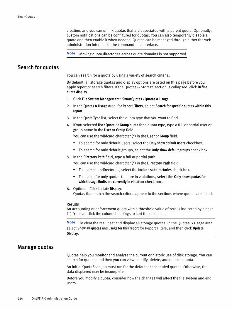
creation, and you can unlink quotas that are associated with a parent quota. Optionally,custom notifications can be configured for quotas. You can also temporarily disable aquota and then enable it when needed. Quotas can be managed through either the webadministration interface or the command-line interface.
Moving quota directories across quota domains is not supported.
Search for quotasYou can search for a quota by using a variety of search criteria.
By default, all storage quotas and display options are listed on this page before youapply report or search filters. If the Quotas & Storage section is collapsed, click Definequota display.
1. Click File System Management > SmartQuotas > Quotas & Usage.
2. In the Quotas & Usage area, for Report Filters, select Search for specific quotas within thisreport.
3. In the Quota Type list, select the quota type that you want to find.
4. If you selected User Quota or Group quota for a quota type, type a full or partial user orgroup name in the User or Group field.
You can use the wildcard character (*) in the User or Group field.
l To search for only default users, select the Only show default users checkbox.
l To search for only default groups, select the Only show default groups check box.
5. In the Directory Path field, type a full or partial path.
You can use the wildcard character (*) in the Directory Path field.
l To search subdirectories, select the Include subdirectories check box.
l To search for only quotas that are in violations, select the Only show quotas forwhich usage limits are currently in violation check box.
6. Optional: Click Update Display.Quotas that match the search criteria appear in the sections where quotas are listed.
ResultsAn accounting or enforcement quota with a threshold value of zero is indicated by a dash(–). You can click the column headings to sort the result set.
To clear the result set and display all storage quotas, in the Quotas & Usage area,select Show all quotas and usage for this report for Report Filters, and then click UpdateDisplay.
Manage quotasQuotas help you monitor and analyze the current or historic use of disk storage. You cansearch for quotas, and then you can view, modify, delete, and unlink a quota.
An initial QuotaScan job must run for the default or scheduled quotas. Otherwise, thedata displayed may be incomplete.
Before you modify a quota, consider how the changes will affect the file system and endusers.
SmartQuotas
224 OneFS 7.0 Administration Guide

u The options to edit or delete a quota appear only when the quota is not linked to adefault quota.
u The option to unlink a quota is available only when the quota is linked to a defaultquota.
1. Click File System Management > SmartQuotas > Quotas & Usage.
2. From the Quota Report options, select the type of quota report that you want to view ormanage.l To monitor and analyze current disk storage use, click Show current quotas and
usage (Live Report).
l To monitor and analyze historic disk storage use, click Show archived quota report toselect from the list of archived scheduled and manually generated quota reports.
3. For Report Filters, select the filters to be used for this quota report.l To view all information in the quota report, click Show all quotas and usage for this
report.
l To filter the quota report, click Search for specific quotas within this report, and thenselect the filters that you want to apply.
4. Click Update Display.The quota report displays below.
5. Optional: Select a quota to view its settings or to perform the following managementactions.l To review or edit this quota, click View details.
l To delete this quota, click Delete.
l To unlink a linked quota, click Unlink.
Configuration changes for linked quotas must be made on the parent(default) quota that the linked quota is inheriting from. Changes to the parentquota are propagated to all children. If you want to override configuration from theparent quota, you must first unlink the quota.
Export a quota configuration fileYou can export quota settings in the form of a configuration file, which can then beimported for reuse to another OneFS cluster. You can also store the exported quotaconfigurations in another location outside of the cluster.
You can pipe the XML output to a file or directory. The XML file can then be imported toanother cluster.
1. Establish an SSH connection to any node in the cluster.
2. At the command prompt, run the following command:isi_classic quota list --exportThe quota configuration file displays as raw XML.
Import a quota configuration fileYou can import quota settings in the form of a configuration file that has been exportedfrom another OneFS cluster.
1. Establish an SSH connection to any node in the cluster.
SmartQuotas
Export a quota configuration file 225

2. Navigate to the location of the exported quota configuration file.
3. At the command prompt, run the following command, where <filename> is the nameof an exported configuration file:isi_classic quota import --from-file=<filename>The system parses the file and imports the quota settings from the configuration file.Quota settings that you configured before importing the quota configuration file areretained, and the imported quota settings are effective immediately.
Managing quota notificationsQuota notifications can be enabled or disabled, modified, and deleted.
By default, a global quota notification is already configured and applied to all quotas.You can continue to use the global quota notification settings, modify the globalnotification settings, or disable or set a custom notification for a quota.
Enforcement quotas support four types of notifications and reminders:
u Threshold exceeded
u Over-quota reminder
u Grace period expired
u Write access denied
If a directory service is used to authenticate users, you can configure notificationmappings that control how email addresses are resolved when the cluster sends a quotanotification. If necessary, you can remap the domain that is used for quota emailnotifications and you can remap Active Directory domains, local UNIX domains, or both.
Configure default quota notification settingsYou can configure default global quota notification settings that apply to all quotas of aspecified threshold type.
The custom notification settings that you configure for a quota take precedence over thedefault global notification settings.
1. Click File System Management > SmartQuotas > Settings.
2. Optional: On the Quota Settings page, for Scheduled Reporting, select On.
3. Click Change Schedule, and then select a report frequency from the list.Reporting schedule settings appear for the frequency that you selected.
4. Select the reporting schedule options that you want, and then click Select.
5. In the Scheduled Report Archiving area, you can configure the following size anddirectory options:l To configure the number of live reports that you want to archive, type the number
of reports in the Limit archive size field.
l To specify an archive directory that is different from the default, in the ArchiveDirectory field, type the path or click Browse to select the path.
6. In the Manual Report Archiving area, you can configure the following size and directoryoptions:l To configure the number of live reports that you want to archive, type the number
of reports in the Limit archive size field.
l To specify an archive directory that is different from the default, in the ArchiveDirectory field, type the path or click Browse to select the path.
SmartQuotas
226 OneFS 7.0 Administration Guide
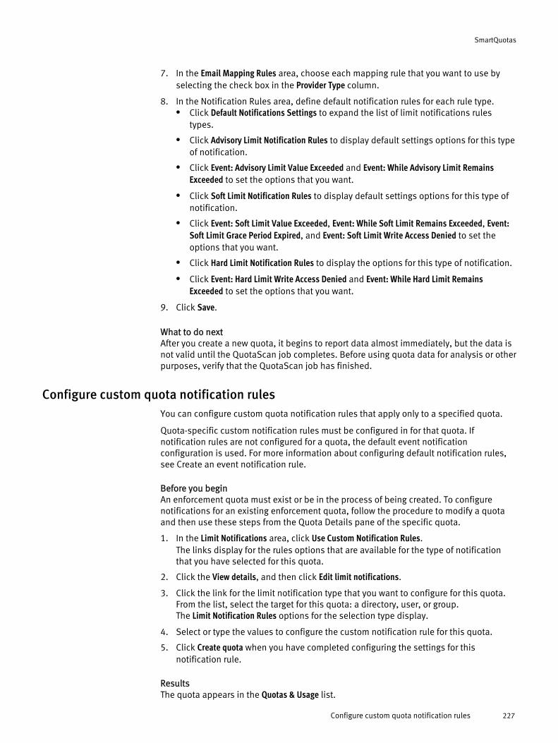
7. In the Email Mapping Rules area, choose each mapping rule that you want to use byselecting the check box in the Provider Type column.
8. In the Notification Rules area, define default notification rules for each rule type.l Click Default Notifications Settings to expand the list of limit notifications rules
types.
l Click Advisory Limit Notification Rules to display default settings options for this typeof notification.
l Click Event: Advisory Limit Value Exceeded and Event: While Advisory Limit RemainsExceeded to set the options that you want.
l Click Soft Limit Notification Rules to display default settings options for this type ofnotification.
l Click Event: Soft Limit Value Exceeded, Event: While Soft Limit Remains Exceeded, Event:Soft Limit Grace Period Expired, and Event: Soft Limit Write Access Denied to set theoptions that you want.
l Click Hard Limit Notification Rules to display the options for this type of notification.
l Click Event: Hard Limit Write Access Denied and Event: While Hard Limit RemainsExceeded to set the options that you want.
9. Click Save.
What to do nextAfter you create a new quota, it begins to report data almost immediately, but the data isnot valid until the QuotaScan job completes. Before using quota data for analysis or otherpurposes, verify that the QuotaScan job has finished.
Configure custom quota notification rulesYou can configure custom quota notification rules that apply only to a specified quota.
Quota-specific custom notification rules must be configured in for that quota. Ifnotification rules are not configured for a quota, the default event notificationconfiguration is used. For more information about configuring default notification rules,see Create an event notification rule.
Before you beginAn enforcement quota must exist or be in the process of being created. To configurenotifications for an existing enforcement quota, follow the procedure to modify a quotaand then use these steps from the Quota Details pane of the specific quota.
1. In the Limit Notifications area, click Use Custom Notification Rules.The links display for the rules options that are available for the type of notificationthat you have selected for this quota.
2. Click the View details, and then click Edit limit notifications.
3. Click the link for the limit notification type that you want to configure for this quota.From the list, select the target for this quota: a directory, user, or group.The Limit Notification Rules options for the selection type display.
4. Select or type the values to configure the custom notification rule for this quota.
5. Click Create quota when you have completed configuring the settings for thisnotification rule.
ResultsThe quota appears in the Quotas & Usage list.
SmartQuotas
Configure custom quota notification rules 227

What to do nextAfter you create a new quota, it begins to report data almost immediately, but the data isnot valid until the QuotaScan job completes. Before using quota data for analysis or otherpurposes, verify that the QuotaScan job has finished.
Map an email notification rule for a quotaEmail notification mapping rules control how email addresses are resolved when thecluster sends a quota notification.
If necessary, you can remap the domain used for SmartQuotas email notifications. Youcan remap Active Directory Windows domains, local UNIX domains, or NIS domains.
1. Click File System Management > SmartQuotas > Settings.
2. Optional: In the Email Mapping area, click Create an email mapping rule.The settings for email mapping rules appear.
3. From the Provider Type list
4. From the Current Domain list, select the domain that you want to use for the mappingrule.
5. In the Map-to-Domain field, type the name of the domain that you want to map emailnotifications to.
Repeat this step if you want to map more than one domain.
6. Click Save Rule.A message displays indicating that your email mapping rule has been created andthat the mapping rule is added to the Email Mapping Rules list.
Configure a custom email quota notification templateIf email notifications are enabled, you can configure custom templates for emailnotifications.
If the default email notification templates do not meet your needs, you can configure yourown custom email notification templates by using a combination of text and SmartQuotasvariables.
1. Open a text editor and create a .txt file that includes any combination of text andOneFS email notification variables.
2. Save the template file as ASCII text or in ISO-8859-1 format.
3. Upload the file to an appropriate directory on the OneFS cluster.
For example, /ifs/templates.
Example 1 Example of a custom quota email notification text file
The following example illustrates a custom email template to notify recipients about anexceeded quota.Text-file contents with variables
The disk quota on directory <ISI_QUOTA_PATH> owned by<ISI_QUOTA_OWNER> was exceeded.The <ISI_QUOTA_TYPE> quota limit is <ISI_QUOTA_THRESHOLD>, and<ISI_QUOTA_USAGE> is in use. Please free some disk spaceby deleting unnecessary files.For more information, contact Jane Anderson in IT.
Email contents with resolved variables
The disk quota on directory
SmartQuotas
228 OneFS 7.0 Administration Guide

Example 1 Example of a custom quota email notification text file (continued, page X of Y)
/ifs/data/sales_tools/collateral owned by jsmith was exceeded.The hard quota limit is 10 GB, and 11 GB is in use. Pleasefree some disk space by deleting unnecessary files.For more information, contact Jane Anderson in IT.
What to do nextTo use the custom template, click Cluster Managements > General Settings > Email Settings,and then select the custom template in the Event Notification Settings area.
Managing quota reportsReports can be created, configured, and scheduled to monitor, track, and analyze storageuse on a OneFS cluster.
You can view and schedule reports and customize report settings to track, monitor, andanalyze disk storage use. Quota reports are managed by configuring settings that giveyou control over when reports are scheduled, how they are generated, where and howmany are stored, and how they are viewed. The maximum number of scheduled reportsthat are available for viewing in the web-administration interface can be configured foreach report type. When the maximum number of reports are stored, the system deletesthe oldest reports to make space for new reports as they are generated.
Create a quota report scheduleYou can configure quota report settings to generate the quota report on a specifiedschedule.
These settings determine whether and when scheduled reports are generated, and whereand how the reports are stored. If you disable a scheduled report, you can still rununscheduled reports at any time.
1. Click File System Management > SmartQuotas > Settings.
2. Optional: On the Quota settings page, for Scheduled Reporting, click On.The Report Frequency option appears.
3. Click Change schedule, and then select the report frequency that you want to set fromthe list.Reporting schedule settings appear that are specific to the reporting frequency thatyou selected.
4. Select the reporting schedule options that you want.
5. Click Save.
ResultsReports are generated according to your criteria and can be viewed in the GeneratedReports Archive.
Generate a quota reportIn addition to scheduled quota reports, you can generate a report to capture usagestatistics at a point in time.
Before you beginQuotas must exist and the initial QuotaScan job must run before you can generate aquota report.
1. Click File System Management > SmartQuotas > Generated Reports Archive.
SmartQuotas
Managing quota reports 229

2. In the Generated Quota Reports Archive area, click Generate a quota report.The Generate a Quota Report area appears.
3. Click Generate Report.
ResultsThe new report appears in the Quota Reports list.
Locate a quota reportYou can locate quota reports, which are stored as XML files, and then use your own toolsand transforms to view them.
1. Establish an SSH connection to any node in the cluster.
2. Navigate to the directory where quota reports are stored. The following path is thedefault quota report location:
/ifs/.isilon/smartquotas/reportsIf quota reports are not in the default directory, you can run the isi quota settingscommand to find the directory where they are stored.
3. At the command prompt, run one of the following commands:
To view a list of all quota reports in the specifieddirectory
Run the following command:
ls -a *.xml
To view a specific quota report in the specifieddirectory
Run the following command:
ls <filename>.xml
Basic quota settingsWhen you create a storage quota, the following attributes must be defined, at aminimum. When you specify usage limits, more options are available for defining yourquota.
Option Description- -Directory Path The directory that the quota is on.
User Quota Select to automatically create a quota forevery current or future user that stores data inthe specified directory.
Group Quota Select to automatically create a quota forevery current or future group that stores datain the specified directory.
Include Snapshot Data Select to count all snapshot data in usagelimits; cannot be changed after the quota iscreated.
Include Data-Protection Overhead Select to count protection overhead in usagelimits.
No Usage Limit Select to account for usage only.
SmartQuotas
230 OneFS 7.0 Administration Guide
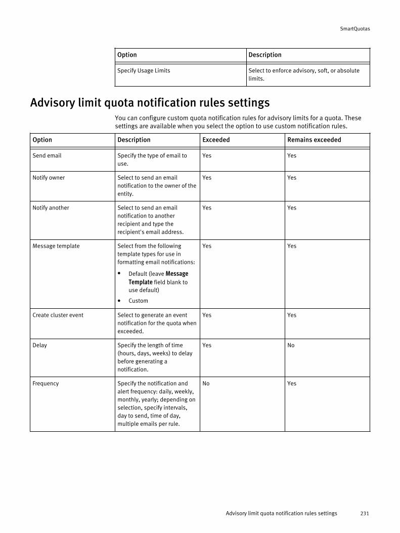
Option Description- -Specify Usage Limits Select to enforce advisory, soft, or absolute
limits.
Advisory limit quota notification rules settingsYou can configure custom quota notification rules for advisory limits for a quota. Thesesettings are available when you select the option to use custom notification rules.
Option Description Exceeded Remains exceeded- - - -Send email Specify the type of email to
use.Yes Yes
Notify owner Select to send an emailnotification to the owner of theentity.
Yes Yes
Notify another Select to send an emailnotification to anotherrecipient and type therecipient's email address.
Yes Yes
Message template Select from the followingtemplate types for use informatting email notifications:
l Default (leave MessageTemplate field blank touse default)
l Custom
Yes Yes
Create cluster event Select to generate an eventnotification for the quota whenexceeded.
Yes Yes
Delay Specify the length of time(hours, days, weeks) to delaybefore generating anotification.
Yes No
Frequency Specify the notification andalert frequency: daily, weekly,monthly, yearly; depending onselection, specify intervals,day to send, time of day,multiple emails per rule.
No Yes
SmartQuotas
Advisory limit quota notification rules settings 231

Soft limit quota notification rules settingsYou can configure custom soft limit notification rules for a quota. These settings areavailable when you select the option to use custom notification rules.
Option Description Exceeded Remainsexceeded
Grace periodexpired
Write accessdenied
- - - - - -Send email Specify the
recipient of theemail notification.
Yes Yes Yes Yes
Notify owner Select to send anemail notification tothe owner of theentity.
Yes Yes Yes Yes
Notify another Select to send anemail notification toanother recipientand type therecipient's emailaddress.
Yes Yes Yes Yes
Message template Select from thefollowing templatetypes for use informatting emailnotifications:
l Default (leaveMessageTemplate fieldblank to usedefault)
l Custom
Yes Yes Yes Yes
Create cluster event Select to generatean eventnotification for thequota.
Yes Yes Yes Yes
Delay Specify the lengthof time (hours,days, weeks) todelay beforegenerating anotification.
Yes No No Yes
Frequency Specify thenotification andalert frequency:daily, weekly,monthly, yearly;depending onselection, specifyintervals, day to
No Yes Yes No
SmartQuotas
232 OneFS 7.0 Administration Guide

Option Description Exceeded Remainsexceeded
Grace periodexpired
Write accessdenied
- - - - - -send, time of day,multiple emails perrule.
Hard limit quota notification rules settingsYou can configure custom quota notification rules for hard limits for a quota. Thesesettings are available when you select the option to use custom notification rules.
Option Description Write access denied Exceeded- - - -Send email Specify the recipient of the
email notification.Yes Yes
Notify owner Select to send an emailnotification to the owner of theentity.
Yes Yes
Notify another Select to send an emailnotification to anotherrecipient and type therecipient's email address.
Yes Yes
Message template Select from the followingtemplate types for use informatting email notifications:
l Default (leave MessageTemplate field blank touse default)
l Custom
Yes Yes
Create cluster event Select to generate an eventnotification for the quota whenexceeded.
Yes Yes
Delay Specify the length of time(hours, days, weeks) to delaybefore generating anotification.
Yes No
Frequency Specify the notification andalert frequency: daily, weekly,monthly, yearly; depending onselection, specify intervals,day to send, time of day,multiple emails per rule.
No Yes
Limit notification settingsYou have three notification options when you create an enforcement quota: turn offnotifications, use default rules, or define custom rules. Enforcement quotas support the
SmartQuotas
Hard limit quota notification rules settings 233

following notification settings for each threshold type. A quota can use only one of thesesettings.
Notification setting Description- -Use Default Notification Rules Uses the default notification rules that you
configured for the specified threshold type.
Turn Off Notifications for this Quota Disables all notifications for the quota.
Use Custom Notification Rules Provides settings to create basic customnotifications that apply to only this quota.
Quota report settingsYou can configure quota report settings that track disk usage. These settings determinewhether and when scheduled reports are generated, and where and how reports arestored.
Setting Description Notes- - -Scheduled reporting Enables or disables the scheduled
reporting feature.
l Off. Manually generated on-demandreports can be run at any time.
l On. Reports run automaticallyaccording to the schedule that youspecify.
Report frequency Specifies the interval for this report to run:daily, weekly, monthly, or yearly; you canfurther refine the report schedule by usingthe following options.
Generate report every. Specify the
numeric value for the selected reportfrequency; for example, every 2 months.
Generate reports on. Select the day or
multiple days to generate reports.
Select report day by. Specify date or day
of the week to generate the report.
Generate one report per specified by. Set
the time of day to generate this report.
Generate multiple reports per specifiedday. Set the intervals and times of day to
generate the report for that day.
Scheduled report archiving Determines the maximum number ofscheduled reports that are available forviewing on the SmartQuotas Reportspage.
Limit archive size for scheduled reports to
a specified number of reports. Type the
When the maximum number of reports arestored, the system deletes the oldestreports to make space for new reports asthey are generated.
SmartQuotas
234 OneFS 7.0 Administration Guide

Setting Description Notes- - -
integer to specify the maximum number ofreports to keep.
Archive Directory. Browse to the directory
where you want to store quota reports forarchiving.
Manual report archiving Determines the maximum number ofmanually generated (on-demand) reportsthat are available for viewing on theSmartQuotas Reports page.
Limit archive size for live reports to a
specified number of reports. Type theinteger to specify the maximum number ofreports to keep.
Archive Directory. Browse to the directory
where you want to store quota reports forarchiving.
When the maximum number of reports arestored, the system deletes the oldestreports to make space for new reports asthey are generated.
Custom email notification template variable descriptionsIf the default OneFS email notification templates do not meet your needs, you canconfigure and upload your own custom email templates for SmartQuotas notifications.
An email template can contain text and, optionally, variables that represent values. Youcan use any of the SmartQuotas variables in your templates. Template files must besaved as a .txt file.
Variable Description Example- - -ISI_QUOTA_PATH Path of quota domain /ifs/data
ISI_QUOTA_THRESHOLD Threshold value 20 GB
ISI_QUOTA_USAGE Disk space in use 10.5 GB
ISI_QUOTA_OWNER Name of quota domain owner jsmith
ISI_QUOTA_TYPE Threshold type Advisory
ISI_QUOTA_GRACE Grace period, in days 5 days
ISI_QUOTA_EXPIRATION Expiration date of grace period Fri Feb 23 14:23:19 PST 2007
SmartQuotas
Custom email notification template variable descriptions 235

SmartQuotas
236 OneFS 7.0 Administration Guide

CHAPTER 12
Storage pools
Storage pools are a logical division of nodes and files. They give you the ability toaggregate and manage large numbers of files from a single management interface. OneFSuses storage pools to efficiently manage and protect the data on a cluster.
Node pools are sets of like nodes that are grouped into a single pool of storage. Nodepool membership changes automatically through the addition or removal of nodes to orfrom the cluster. File pools are user-defined logical groupings of files that are stored innode pools according to file pool policies. By default, the basic unlicensed technology isimplemented in a cluster, and additional features are available when you license theSmartPools module. These licensed features include the ability to create multiple filepools and file pool policies that direct specific files and directories to a targeted nodepool or tier and spillover management, which enables you to define how write operationsare handled when a node pool or tier is full. Virtual hot spare allocation, which reservesspace for data re-protection if a drive fails, is available with both the licensed andunlicensed technology.
The following table compares licensed and unlicensed storage pool features.
Feature Unlicensed Licensed- - -Automatic pool provisioning Yes Yes
Spillover Undirected Configurable
Policy-based data movement No Yes
Virtual hot spare Yes Yes
u Storage pool overview.........................................................................................238u Autoprovisioning.................................................................................................238u Virtual hot spare and SmartPools........................................................................239u Spillover and SmartPools....................................................................................239u Node pools.........................................................................................................240u SSD pools...........................................................................................................241u File pools with SmartPools..................................................................................241u Tiers....................................................................................................................242u File pool policies.................................................................................................243u Pool monitoring...................................................................................................243u Creating file pool policies with SmartPools..........................................................244u Managing file pool policies.................................................................................245u SmartPools settings............................................................................................248u Default file pool protection settings.....................................................................250u Default file pool I/IO optimization settings..........................................................252
Storage pools 237

Storage pool overviewOneFS provides storage pools to simplify the management and storage of data. Filepools, node pools, and tiers are types of storage pools.
Node pools are physical nodes that are grouped by type to optimize reliability and dataprotection settings. Node pools are created automatically, or autoprovisioned, by OneFSwhen the system is installed and whenever nodes are added or removed. Tiers arecollections of node pools that are grouped to optimize storage according to need, such asa mission-critical high-speed tier or node pools that are best suited to data archiving. Thelicensed SmartPools technology gives you the ability to create file pools, which arelogical collections of files. Membership in a file pool is determined by criteria-basedrules, called file pool policies, that specify operations to determine which storage poolsstore the data.
By default, the basic storage pool feature creates one file pool for the OneFS cluster. Thisfile pool provides a single point of management and a single namespace for the cluster.The licensed SmartPools module enables you to create multiple file pools according tofile attributes and to direct spillover to a target tier or node pool. Using the licensedmodule, you can create multiple storage pools and apply pool policies to manage filestorage according to the criteria that you specify. OneFS includes the following basicfeatures.
u Node pools — Groups of equivalent nodes that are associated in a single pool of storage.
u Tiers — Groups of node pools, used to optimize data storage according to OneFS platformtype.
OneFS adds the following features when the SmartPools module is licensed.
u Custom file pools — Storage pools that you define to filter files and directories intospecific node pools according to your criteria. Using file attributes such as file size, type,access time, and location that you specify in a file pool policy , custom file pools automatedata movement and storage according to your unique storage needs. The licensed module alsoincludes customizable template policies that are optimized for archiving, extra protection,performance, and VMware files.
u Storage pool spillover — Automated node-capacity overflow management. Spilloverdefines how to handle write operations when a storage pool is not writable. When spillover isenabled, data is redirected to a specified storage pool. If spillover is disabled, new data writesfail and an error message appears.
If the SmartPools module is not licensed, files are stored on any availablenode pools across the cluster.
AutoprovisioningAutoprovisioning is the process of automatically assigning storage by node type toimprove the performance and reliability of the file storage system.
When you configure a cluster, OneFS automatically assigns nodes to node pools, orautoprovisions, in your cluster to increase data-protection and cluster reliability.Autoprovisioning reduces the time required for the manual management tasks associatedwith configuring storage pools and resource planning.
Storage pools
238 OneFS 7.0 Administration Guide

Nodes are not provisioned, meaning they are not associated with each other andnot writable, until at least three nodes of an equivalence class are assigned to the pool. Ifyou have added only two nodes of an equivalence class to your cluster, there is nocommunication between nodes until one more is added.If you remove nodes from a provisioned cluster so that fewer than three equivalence-class nodes remain, the pool is underprovisioned. In this situation, when two like nodesremain, they are still writable; if only one node remains, it is not writable but it remainsreadable.
Node pool attributes and status are visible in the web administration interface. You canview storage pool health information through the command-line interface also.
Virtual hot spare and SmartPoolsVirtual hot spare allocation allows you to allocate space to be used to protect data in theevent of a drive failure.
The virtual hot spare option reserves the free space needed to rebuild the data if a diskfailure occurs. For example, if you specify two virtual drives and 15 percent, each nodepool reserves virtual drive space that is equivalent to two drives or 15 percent of theirtotal capacity for virtual hot spare, whichever is larger.
You can reserve space in node pools across the cluster for this purpose, up to theequivalent of a maximum of four full drives. Virtual hot spare allocation is defined usingthese options:
u A minimum number of virtual drives in the node pool (1-4).
u A minimum percentage of total disk space (0-20 percent) .
u A combination of minimum virtual drives and total disk space.
The larger number of the two determines the space allocation, not the sum ofthe numbers.
It is important to understand the following information when configuring VHS settings:
u If you configure both settings, the enforced minimum value satisfies bothrequirements.
u If you select the option to reduce the amount of available space, free-spacecalculations do not include the space reserved for the virtual hot spare. The reservedvirtual hot spare free space is used for write operations unless you select the optionto deny new data writes. If Reduce amount of available space is enabled while Deny newdata writes is disabled, it is possible for the file system to report utilization as morethan 100 percent.
Virtual hot spare reservations affect spillover. For example, if the virtual hot sparereservation is 10 percent of storage pool capacity, spillover occurs when the storage poolis 90 percent full.
Spillover and SmartPoolsWhen SmartPools is licensed, a specific storage pool can be designated to receive spilldata when a file pool target is not writable. If spillover is undesirable, it can be disabledso that writes do not occur.
Spillover management is a feature that is available when the SmartPools module islicensed. Write operations can be directed to a specified node pool or tier in the clusterwhen there is not enough space to write a file according to the file pool policy rules.
Storage pools
Virtual hot spare and SmartPools 239

Virtual hot spare reservations affect spillover. For example, if the virtual hot sparereservation is 10 percent of storage pool capacity, spillover occurs when the storage poolis 90 percent full.
Node poolsA node pool is a logical grouping of equivalent nodes across the cluster. OneFS nodes aregrouped automatically to create a storage pool for ease of administration and applicationof file pool target policies.
Each node in the OneFS clustered storage system is a peer, and any node can handle adata request. File pool policies can then be applied to files to target node pools that havedifferent performance and capacity characteristics to meet different workflowrequirements. Each node that is added to a cluster increases aggregate disk, cache, CPU,and network capacity. When additional nodes are added to the cluster, they areautomatically added to node pools according to matching attributes, such as drive size,RAM, series, and SSD-node ratio.
Add or move node pools in a tierYou can group node pools into tiers and move node pools among tiers to most efficientlyuse resources or for other cluster management purposes.
1. Click File System Management > SmartPools > Summary.The SmartPools page appears and displays two groupings: the current capacity usageand a list of tiers and node pools.
2. In the Tiers & Node Pools area, select and drag a node pool to the tier name to add it tothe tier.To add a node pool that is currently in another tier, expand that tier and drag anddrop the node pool to the target tier name.
3. Continue dragging and dropping node pools until you complete the tier.Each node that you added to the tier appears under the tier name when it is in anexpanded state.
Change the name or protection level of a node poolYou can change the name or protection level of a node pool.
1. Click File System Management > SmartPools > Summary.The SmartPools page appears and displays two groupings: current capacity usageand a list of tiers and node pools.
2. In the Tiers & Node Pools section, in the row of the node pool that you want tomodify, click Edit.A dialog box appears.
3. Type a name for this node pool, select a protection level from the list, or do both.
A node pool name can contain alphanumeric characters but cannot begin with anumber.
4. Click Submit.The node pool appears in the list of tiers and node pools.
Storage pools
240 OneFS 7.0 Administration Guide

SSD poolsOneFS clusters can contain both HDDs and SSDs. When OneFS autoprovisions nodes,nodes with SSDs are grouped into equivalent node pools. Your SSD strategy defines howSSDs are used within the cluster.
Clusters that include both hard-disk drives (HDDs) and solid-state drives (SSDs) can beoptimized by your SSD strategy options to increase performance across a wide range ofworkflows. SSD strategy is applied on a per file basis. When you select your optionsduring the creation of a file pool policy, you can identify the directories and files in theOneFS cluster that require faster or slower performance. OneFS automatically moves thatdata to the appropriate pool and drive type.
Global namespace acceleration (GNA) allows data stored on node pools without SSDs touse SSDs elsewhere in the cluster to store extra metadata mirrors, which acceleratesmetadata read operations. To avoid overloading node pools with SSDs, certainthresholds must be satisfied for GNA to be enabled. GNA can be enabled if 20% or moreof the nodes in the cluster contain at least one SSD and 1.5% or more of the total clusterstorage is SSD-based. For best results, ensure that at least 2.0% of the total clusterstorage is SSD-based before enabling global namespace acceleration.
If the ratio of accessible SSD-containing nodes in the cluster drops below the20% requirement, GNA is not active despite being enabled. GNA is reactivated when theratio is corrected.
The following SSD strategy options are listed in order of slowest to fastest choices.
u Avoid SSDs — Writes all associated file data and metadata to HDDs only.
Use this option to free SSD space only after consulting with Isilon Technical Supportpersonnel. Using this strategy may negatively affect performance.
u Metadata read acceleration — This is the default setting. Writes both file data andmetadata to HDDs. An extra mirror of the file metadata is written to SSDs, if available. The SSDmirror is in addition to the number required to satisfy the protection level. Enabling GNA makesread acceleration available to files in node pools that do not contain SSDs. GNA is only formetadata and extra mirrors.
u Metadata read/write acceleration — Writes file data to HDDs and metadata to SSDs,when available. This strategy accelerates metadata writes in addition to reads but requiresabout four to five times more SSD storage than the Metadata read acceleration setting.Enabling GNA does not affect read/write acceleration.
u Data on SSDs — Uses SSD node pools for both data and metadata. Regardless of whetherglobal namespace acceleration is enabled, any SSD blocks reside on the file target pool if thereis room. This SSD strategy does not result in the creation of additional mirrors beyond thenormal protection level but requires significantly increased storage requirements comparedwith the other SSD strategy options.
File pools with SmartPoolsFile pools provide policy-based control of the storage characteristics of your files. Bydefault, all files in the cluster belong to a single file pool, which is defined by the defaultfile pool policy. Additional file pools can be created when you license the SmartPoolsmodule.
Using the licensed SmartPools module, you can create multiple file pools, which are user-defined file aggregates that are governed by automated file pool policies. By applying file
Storage pools
SSD pools 241

pool policies to file pools, data can be moved automatically from one type of storage toanother within a single cluster from a single point of management to meet performance,space, cost, or other requirements while retaining protection-level settings.
File pool policies are based on the file attributes that you specify. For example, a file poolpolicy can be created for an specific file extension that requires high availability, so youcan target a pool that provides the fastest reads or read/writes. Another file pool policycan be created to evaluate last accessed date, allowing you to target node pools bestsuited for archiving for historical or regulatory purposes.
TiersA tier is a user-defined collection of node pools that can be used as a target for a file poolpolicy.
You can create tiers to assign your data to any of the node pools in the tier to meet yourdata-classification needs. For example, a collection of node pools can be assigned to atier that you create for frequently accessed or mission-critical data that requires highavailability and fast access. In a three-tier system, this classification may be Tier 1. Youcan classify data that is used less frequently or that is accessed by fewer users as Tier-2data. Tier-3 usually comprises data that is seldom used and can be archived for historicalor regulatory purposes.
A node pool can belong to only one tier.
Create a tierYou can group node pools into a tier that can be used as a target for a file pool policy.
1. Click File System Management > SmartPools > Summary.The SmartPools page appears and displays two groupings: the current capacity usageand a list of tiers and node pools.
2. In the Tiers & Node Pools section, click Create a Tier.
3. In the dialog box that displays, type a name for this tier, and then click Submit.The tier appears in the list of tiers and node pools.
4. Select and drag a node pool to the tier name to add it to the tier. Continue draggingand dropping node pools until you complete the tiered group.Each node pool that you added to the tier appears under the tier name when it is inan expanded state.
Rename a tierYou can modify the name of a tier that contains node pools.
A tier can contain alphanumeric characters but cannot begin with a number.
1. Click File System Management > SmartPools > Summary.The SmartPools page appears and displays two groupings: the current capacity usageand a list of tiers and node pools.
2. In the Tiers & Node Pools area, in the row of the tier you want to rename, click Edit.
3. In the dialog box that displays, type a name for this tier and click Submit.The newly named tier appears in the list of tiers and node pools.
Storage pools
242 OneFS 7.0 Administration Guide

Delete a tierYou can delete a tier, but the option is not available until you move all node pools out ofthat tier.
1. Click File System Management > SmartPools > Summary.The SmartPools page appears and displays two groupings: current capacity usageand a list of tiers and node pools.
2. In the Tiers & Node Pools area, in the row of the tier that you want to delete, click Delete.
3. In the confirmation dialog box that displays, click Yes to confirm the deletion.
ResultsThe tier is removed from list of tiers and node pools.
File pool policiesFile pool policies define file movement among node pools, optimization for file-accesspatterns, and file protection settings. The licensed SmartPools module augments thebasic OneFS storage pool features to give you the ability to create multiple file pools bycreating file pool policies, so you can automatically store files on a specified targetaccording to your criteria.
You configure file pool policies using file attributes that are both system- and user-defined. You can then set protection levels and access attributes for files types that youspecify. Multiple criteria can be defined in one file pool policy, and you can also use time-based filters for the date that a file was last accessed, modified, or created. You can alsodefine a relative elapsed time instead of a date, such as three days before the currentdate.
The unlicensed OneFS storage pool technology allows you to configure the default filepool policy for managing the node pools that are created when the cluster isautoprovisioned. By default, the basic unlicensed storage pools technology isimplemented in a cluster: the default file pool contains all files and is targeted to anynode pool. The single file pool is called the default file pool and is defined by the defaultfile pool policy that is configured in the default file pool policy settings. You cannotreorder or remove the default file pool policy. The settings in the default file pool policyapply to all files that are not covered by another file pool policy. For example, data that isnot covered by a file pool policy can be moved to a tier that you identify as a default forthis purpose.
All file pool policy operations are executed when the SmartPools job runs. When new filesare created, the OneFS system temporarily chooses a node pool for new files, using amechanism based on file pool policies used when the last SmartPools job ran. They arethen moved according to a matching file pool policy when the next SmartPools job runs.
Pool monitoringPool health, performance, and status can be monitored through the web administrationinterface or the command-line interface. Information is displayed for individual nodes,including node-specific network traffic, internal and external network interfaces, anddrive status. You can configure real-time and historical performance to be graphed in theweb administration interface.
You can assess pool health and performance by viewing the following information:
u Subpool statusu Node statusu New events
Storage pools
Delete a tier 243

u Cluster size
u Cluster throughput
u CPU usage
Monitor node pools and tiersYou can view the status and details of node pools and tiers in the SmartPools summary.
Pool names that are longer than 40 characters are truncated by OneFS. To viewthe full pool name, rest the mouse pointer over the shortened name to display a tooltip ofthe long name.
1. Click File System Management > SmartPools > Summary.The SmartPools page appears and displays two groupings: the current capacity usageand a list of tiers and node pools.
2. In the Current Capacity Usage area, move the pointer over the usage bar-graphmeasurements to view details.
3. In the Tiers & Node Pools area, expand any tiers to view all node pool information.
View unhealthy subpoolsWhen subpools are unhealthy, OneFS exposes them in a list.
1. Click File System Management > SmartPools > Summary.The SmartPools page appears and displays three groupings: the current capacityusage, a list of tiers and node pools, and any unhealthy subpools.
2. In the Unhealthy Subpools area, review details of any problematic subpools.
Creating file pool policies with SmartPoolsFile pool policies are used to filter and store files by the attributes and values that youspecify, automating file management and aggregation. SmartPools module must belicensed to create file pool policies.
File pool policies have two parts: the criteria that determine which files are members andthe operations that determine the settings that are applied to member files. Membershipcriteria are defined by tests against file attributes and can be combined with booleanAND and OR operators. Operations are defined by settings for storage target, protectionlevel, and I/O optimization. For example, you can create a file pool policy that identifiesall JPG files that are larger than 2MB and moves them to nearline storage.
The following table lists the file attributes that you can use to define a file pool policy.
File attribute Specifies- -File name Name of the file
Path Where the file is stored
File type File-system object type
File size Size of the file
Modified time When the file was last modified
Create time When the file was created
Storage pools
244 OneFS 7.0 Administration Guide

File attribute Specifies- -Metadata change time When the file metadata was last modified
Access time When the file was last accessed
User attributes Custom attributes
OneFS supports UNIX shell-style (glob) pattern matching for file name attributesand paths, using these characters: *, ?, and [a-z].
As many as four file pool policies can apply to a file (one per action) if the stopprocessing option is not selected. However, if the stop processing option is selectedwhen you create a file-pool policy, only one file pool policy can be applied becauseOneFS applies only the first matching policy rule that it encounters. If a file type matchesmultiple policies, subsequent policies in the list are not evaluated. If one policy rulemoves all JPG files to a nearline node pool and another policy rule moves all files smallerthan 2 MB to a performance tier and the JPG rule is first in the list, then all JPG filessmaller than 2 MB are moved to nearline storage instead of to the performance tier.
OneFS provides customizable template policies that archive older files, increase theprotection level for specified files, send files that are saved to a particular path to ahigher-performance disk pool, and change the access setting for VMWare files. You alsocan copy any file pool policy except the default file pool policy, and then modify thesettings that you need to change. After a file pool policy is created, OneFS stores and listsit with other file pool policies. When the SmartPools job runs, it traverses the stored filepool policies list from top to bottom (per file) and policies are applied in the order of thatlist.
The file pool policy list can be reordered at any time, but the default file poolpolicy is always last in the list of enabled file pool policies.
Managing file pool policiesFile pool policies can be modified, reordered, copied, or removed. The default file poolpolicy can be modified, and template policies can be applied.
You can perform the following file pool policy management tasks:
u Modify file pool policies
u Modify the default file pool policy
u Copy file pool policies
u Use a file pool policy template
u Reorder file pool policies
u Delete file pool policies
Configure default file pool policy settingsYou can configure file pool policies to filter and store files according to criteria that youspecify. File pool policy settings include protection levels and I/O optimization.
1. Click File System Management > SmartPools > Settings.The SmartPools Settings page appears.
2. On the SmartPools Settings page, choose the default settings that you want and clickSubmit.
Storage pools
Managing file pool policies 245
ResultsChanges to the default file pool policy are applied when the next scheduled SmartPoolsjob runs.
Configure default file pool protection settingsYou can configure default file pool protection settings. The default settings are applied toany file that is not covered by another file pool policy.
If existing file pool policies direct data to a specific node pool or tier, do not add ormodify a file pool policy to target anywhere for the Data storage target option. Target aspecific file pool instead.
1. Click File System Management > SmartPools > Settings.The SmartPools page appears.
2. In the SmartPools Settings section, choose the settings that you want apply as theglobal default for Data storage target, Snapshot storage target, or Protection level.
3. Click Submit.The settings that you selected are applied to any entity that is not covered by anotherfile pool policy.
Configure default I/O optimization settingsYou can specify default I/O optimization settings.
1. Click File System Management > SmartPools > Settings.The SmartPools page appears.
2. In the Default File Pool I/O Optimization Settings area, choose the settings that you wantapply as the global default for SmartCache and Data access pattern.
3. Click Submit.The settings that you selected are applied to any entity that is not covered by anotherfile pool policy.
Modify a file pool policyYou can modify the name and description, filter criteria, and the protection and I/Ooptimization settings that are applied to files that are filtered by a file pool policy.
If existing file pool policies direct data to a specific node pool or tier, do not add ormodify a file pool policy to target anywhere for the Data storage target option. Target aspecific file pool instead.
1. Click File System Management > SmartPools > File Pool Policies.The SmartPools page appears and displays three groupings: a list of file poolpolicies, a list of template policies, and latest scan job results.
2. In the File Pool Policies area, in the Actions column of the file pool policy you want tomodify, click Copy.The settings options appear.
3. Make your changes in the appropriate areas and click Submit.
Storage pools
246 OneFS 7.0 Administration Guide

ResultsChanges to the file pool policy are applied when the next scheduled SmartPools job runs.To run the job immediately, click Start SmartPools Job.
Copy a file pool policyYou can copy any file pool policy with the exception of the default file pool policy.Settings for the copied policy can then be modified.
1. Click File System Management > SmartPools > File Pool Policies.The SmartPools page appears and displays three groupings: a list of file poolpolicies, a list of template policies, and latest scan job results.
2. In the File Pool Policies area, click Copy in the Actions column of the file pool policythat you want to copy.The settings options appear.
3. Make changes in the appropriate areas and click Submit.A copy of the file pool policy is added to the list of policies in the File Pool Policiesarea.
ResultsThe copied file pool policy name is prefaced with Copy of, so that you can differentiate itfrom the source policy.
Prioritize a file pool policyFile pool policies are evaluated in descending order according to their position in the FilePool Policies list. You can position a file pool policy to prioritize its position.
By default, new policies are inserted immediately above the default file pool policy,which is always last. You can give a policy higher or lower priority by moving it up or downthe list.
1. Click File System Management > SmartPools > File Pool Policies.The SmartPools page appears and displays three groupings: a list of file poolpolicies, a list of template policies, and the latest scan job results.
2. In the Order column of the File Pool Policies area, select the policy that you want tomove.
3. Click either Move up or Move down until the policy is positioned where you want it inthe order.
Use a file pool template policyYou can use a OneFS template to configure file pool policies.
1. Click File System Management > SmartPools > File Pool Policies.The SmartPools page appears and displays three groupings: a list of file poolpolicies, a list of template policies, and the latest scan job results.
2. In the Action column of the Template Policies area, in the row of the template you wantto use, click Use.The file pool policy settings options appear, with values pre-configured for the type oftemplate that you selected.
3. Optional: Rename the template or modify the template policy settings.
4. Click Submit.
Storage pools
Copy a file pool policy 247

ResultsThe policy is added to the File Pool Policies list.
Delete a file pool policyYou can delete any file pool policy except the default policy.
Because a file pool policy determines the target where a file is stored, when you delete afile pool policy the files that are associated with that policy may be stored on a differenttarget, depending on the settings of a different or the default file pool policy. Files are notmoved to another target until the SmartPools job runs.
1. Click File System Management > SmartPools > File Pool Policies.The SmartPools page appears and displays three groupings: a list of file poolpolicies, a list of template policies, and latest scan job results.
2. In the File Pool Policies area, in the Actions column of the file pool policy you want toremove, click Delete.
3. In the confirmation dialog box, click Yes to confirm the deletion.
ResultsThe file pool policy is removed from the list in the File Pool Policies area.
SmartPools settingsSmartPools settings include directory protection, global namespace acceleration, virtualhot spare, node pool, spillover, protection management, and I/O optimizationmanagement.
Setting Description Notes- - -Directory protection Increases the amount of protection for
directories at a higher level than thedirectories and files that they contain, sothat data that is not lost can still beaccessed.
When devices failures result in data loss(for example, three drives or two nodes ina +2:1 policy), enabling this settingensures that intact data is still accessible.
The option to Protect directories at onelevel higher should be enabled.
When this setting is disabled, thedirectory that contains a file pool isprotected according to your protection-level settings, but the devices used tostore the directory and the file may not bethe same. There is potential to lose nodeswith file data intact but not be able toaccess the data because those nodescontained the directory.
As an example, consider a cluster that hasa +2 default file pool protection settingand no additional file pool policies.OneFS directories are always mirrored, sothey are stored at 3x, which is themirrored equivalent of the +2 default.
This configuration can sustain a failure oftwo nodes before data loss orinaccessibility. If this setting is enabled,all directories are protected at 4x. If thecluster experiences three node failures,although individual files may beinaccessible, the directory tree is
Storage pools
248 OneFS 7.0 Administration Guide
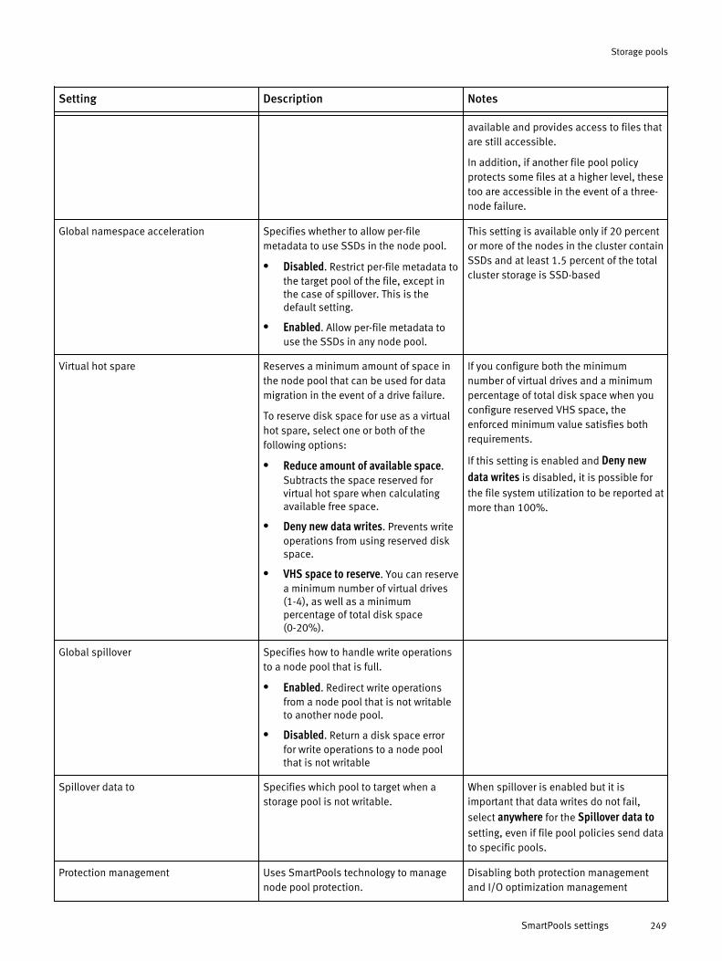
Setting Description Notes- - -
available and provides access to files thatare still accessible.
In addition, if another file pool policyprotects some files at a higher level, thesetoo are accessible in the event of a three-node failure.
Global namespace acceleration Specifies whether to allow per-filemetadata to use SSDs in the node pool.
l Disabled. Restrict per-file metadata tothe target pool of the file, except inthe case of spillover. This is thedefault setting.
l Enabled. Allow per-file metadata touse the SSDs in any node pool.
This setting is available only if 20 percentor more of the nodes in the cluster containSSDs and at least 1.5 percent of the totalcluster storage is SSD-based
Virtual hot spare Reserves a minimum amount of space inthe node pool that can be used for datamigration in the event of a drive failure.
To reserve disk space for use as a virtualhot spare, select one or both of thefollowing options:
l Reduce amount of available space.Subtracts the space reserved forvirtual hot spare when calculatingavailable free space.
l Deny new data writes. Prevents writeoperations from using reserved diskspace.
l VHS space to reserve. You can reservea minimum number of virtual drives(1-4), as well as a minimumpercentage of total disk space(0-20%).
If you configure both the minimumnumber of virtual drives and a minimumpercentage of total disk space when youconfigure reserved VHS space, theenforced minimum value satisfies bothrequirements.
If this setting is enabled and Deny newdata writes is disabled, it is possible for
the file system utilization to be reported atmore than 100%.
Global spillover Specifies how to handle write operationsto a node pool that is full.
l Enabled. Redirect write operationsfrom a node pool that is not writableto another node pool.
l Disabled. Return a disk space errorfor write operations to a node poolthat is not writable
Spillover data to Specifies which pool to target when astorage pool is not writable.
When spillover is enabled but it isimportant that data writes do not fail,
select anywhere for the Spillover data tosetting, even if file pool policies send datato specific pools.
Protection management Uses SmartPools technology to managenode pool protection.
Disabling both protection managementand I/O optimization management
Storage pools
SmartPools settings 249

Setting Description Notes- - -
l SmartPools manages protectionsettings. Specify that SmartPoolsmanages the protection-levelsettings. You can optionally modifythe default settings under Default
l Including files with manually-managed protection settings.Overwrite any protection settings thatwere configured through File SystemExplorer or the command-lineinterface.
settings disables SmartPoolsfunctionality.
I/O optimization management Uses SmartPools technology to managenode pool I/O optimization.
SmartPools manages I/O optimizationsettings. Specify that SmartPools
technology is used to manages I/Ooptimization.
Including files with manually-managedprotection settings. Overwrite any I/O
optimization settings that were configuredthrough File System Explorer or thecommand-line interface
Disabling both protection managementand I/O optimization managementsettings disables SmartPoolsfunctionality.
You can modify the default settings in the
Default I/O Optimization Settings group
(optional).
Default file pool protection settingsDefault protection settings include specifying the data pool, snapshot pool, protectionlevel, and SSD strategy for files that are filtered by the default file pool policy.
Setting Description Notes- - -Data storage target Specifies the node pool or tier
that you want to target withthis file pool policy.
If existing file pool policiesdirect data to a specificnode pool or tier, do notadd or modify a file poolpolicy to target anywhere forthe Data storage targetoption. Target a specific filepool instead.
Select one of the followingoptions to define your SSDstrategy:
u Metadata readacceleration — Default. Write both file
If GNA is notenabled and the pool thatyou choose to target doesnot contain SSDs, youcannot define a strategy.
Metadata read accelerationwrites both file data andmetadata to HDD pools butadds an additional SSD mirrorif possible to accelerate readperformance. Uses HDDs toprovide reliability and an SSD,if available, to improve readperformance. Recommendedfor most uses.
When you select Metadataread/write acceleration, the
strategy uses SSDs, if available
Storage pools
250 OneFS 7.0 Administration Guide

Setting Description Notes- - -
data and metadata toHDDs and metadata toSSDs. Acceleratesmetadata reads only.Uses less SSD space thanthe Metadata read/writeacceleration setting.
u Metadata read/writeacceleration — Writemetadata to SSD pools.Uses significantly moreSSD space than Metadataread acceleration, butaccelerates metadatareads and writes.
u Avoid SSDs — Write allassociated file data andmetadata to HDDs only.
Use this to free SSDspace only afterconsulting with IsilonTechnical Supportpersonnel; maynegatively affectperformance.
u Data on SSDs — Usenodes with SSDs for bothdata and metadata.Regardless of whetherglobal namespaceacceleration is enabled,any SSD blocks reside onthe file target pool if thereis room.
in the file pool policy, forperformance and reliability.The extra mirror may be from adifferent node pool using GNAenabled or from the same nodepool.
The Data on SSDs strategy
does not result in the creationof additional mirrors beyondthe normal protection level.Both file data and metadataare stored on SSDs if availablewithin the file pool policy. Thisoption requires a significantamount of SSD storage.
Snapshot storage target Specifies the node pool or tierthat you want to target forsnapshot storage with this filepool policy. The settings arethe same as those for Datastorage target, but apply tosnapshot data.
Notes for Data storage targetapply to snapshot storagetarget
Protection level Default protection level of diskpool. Assign the default
protection policy of the diskpool to the filtered files.
To change the protection policyto a specific level, select a newvalue from the list.
Storage pools
Default file pool protection settings 251

Setting Description Notes- - -
Specific level. Assign a
specified protection policy tothe filtered files.
Default file pool I/IO optimization settingsYou can manage the I/O optimization settings that are used in the default file pool policy,including files with manually-managed attributes.
To allow SmartPools to overwrite optimization settings that were configured using FileSystem Explorer or the isi set command, select the Including files with manually-managed I/O optimization settings option in the Default Protection Settings group.
Setting Description Notes- - -SmartCache Enables or disables SmartCache. SmartCache can improve performance,
but can also lead to data loss if a nodeloses power or crashes whileuncommitted data is in the write cache.
Data access pattern Defines the optimization settings foraccessing data: Concurrency, Streaming,or Random.
By default, iSCSI LUNs are configured touse a random access pattern.
Other files and directories use aconcurrent access pattern by default.
Storage pools
252 OneFS 7.0 Administration Guide

CHAPTER 13
Networking
After you determine the topology of your network, you can set up and manage yourinternal and external networks.
There are two types of networks associated with a cluster:
u Internal — Nodes use the internal network to communicate with one another.Communication occurs through InfiniBand connections. You can optionally configure a failovernetwork for redundancy.
u External — Clients connect to the cluster through the external network with Ethernet. TheIsilon cluster supports standard network communication protocols, including NFS, SMB, HTTP,and FTP. The cluster includes various external Ethernet connections, providing flexibility for awide variety of network configurations. External speeds vary by product.
With the cluster's web administration interface, you can manage both the internal andexternal network settings from a centralized location.
u Cluster internal network overview........................................................................254u External client network overview.........................................................................254u Configuring the internal cluster network..............................................................259u Configuring an external network..........................................................................261u Managing external client connections with SmartConnect...................................275u Managing network interface provisioning rules....................................................276
Networking 253

Cluster internal network overviewThe internal networks enable communication between nodes in a cluster. You canconfigure a single internal network, or optionally specify a second internal network thatincludes internal network failover if either the int-a or int-b switch is unavailable.
If your network topology uses a single internal network, only the int-a interface must beconfigured. If your network topology uses more than one internal network, you must firstconfigure the int-a IP address ranges, and then configure the int-b and failover IP addressranges.
Internal IP address rangesThe number of internal IP addresses determines how many nodes can be joined to thecluster.
When you initially configure the cluster, you specify one or more IP address ranges for theinternal network. This range of addresses is used by the nodes to communicate. It isrecommended that you create a range of addresses large enough to add nodes later. Forcertain configuration changes, such as deleting an IP address assigned to a node, thecluster must be rebooted.
If the IP address range defined during the initial configuration is too restrictive for the sizeof the internal network, you can add ranges to the int-a network and int-b network.
Cluster internal network failoverInternal network failover provides redundancy for intra-cluster communications.
To enable an internal failover network, the int-a ports of each node in the cluster must beconnected to one switch, and the int-b ports on each node must be connected to anotherswitch. The failover function is automatically enabled when the following conditions aremet:
u IP address ranges on separate subnets for the int-a, int-b, and failover networks areconfigured.
u The int-b interface is enabled.
Enabling an internal failover network requires that the cluster be rebooted.
External client network overviewClient computers connect to a cluster through the external network. OneFS supportsnetwork subnets, IP address pools, and network provisioning rules.
Subnets simplify front-end network management and provide flexibility in implementingand maintaining the cluster's network. By creating IP address pools within subnets, youcan further partition your network interfaces. External network settings can be configuredonce using provisioning rules and then automatically applied as nodes are added to thecluster.
You must initially configure the default external IP subnet in IPv4 format. Afterconfiguration is complete, you can configure additional subnets using IPv4 or IPv6.
IP address pools can be associated with a node or a group of nodes as well as with theNIC ports on the nodes. For example, based on the network traffic that you expect, youmight decide to establish one subnet for storage nodes and another subnet foraccelerator nodes.
Networking
254 OneFS 7.0 Administration Guide

How you set up your external network subnets depends on your network topology. In abasic network topology where all client-node communication occurs through a singlegateway, only a single external subnet is required. If clients connect through multipleexternal subnets or internal connections, you must configure multiple external networksubnets.
External network settingsYou can configure settings for your external networks through a wizard in the command-line interface.
During the initial cluster setup, you must specify the following information about yourexternal network:
u Netmask
u IP address range
u Gateway
u Domain name server list (optional)
u DNS search list (optional)
u SmartConnect zone name (optional)
u SmartConnect service address (optional)
After you configure these settings, OneFS performs the following actions:
u Creates a default external network subnet called subnet0, with the specifiednetmask, gateway, and SmartConnect service address.
u Creates a default IP address pool called pool0 with the specified IP address range,the SmartConnect zone name, and the external interface of the first node in thecluster as the only member.
u Creates a default network provisioning rule called rule0, which automatically assignsthe first external interface for all newly added nodes to pool0.
u Adds pool0 to subnet0 and configures pool0 to use the virtual IP of subnet0 as itsSmartConnect service address.
u Sets the global, outbound DNS settings to the domain name server list and DNSsearch list, if provided.
After you have configured the network configuration for the cluster through the command-line Configuration wizard, you can make changes to your external network settingsthrough the web administration interface. For example, you can add external networksubnets, or modify existing external network settings such as subnets, IP address pools,and network provisioning rules.
IP address poolsIP address pools are logical network partitions of the nodes and external networkinterfaces that belong to a cluster. IP address pools are also used to configureSmartConnect zones and IP failover support for protocols such as NFS.
IP address pools:u Map available addresses to configured interfaces.
u Belong to external network subnets.
u Allow you to partition your cluster's network interfaces into groups.
u Can be to assigned to groups in your organization.
Networking
External network settings 255

Multiple pools for a single subnet require a configured SmartConnect Advancedlicense.
The IP address pool of a subnet consists of one or more ranges of IP addresses and a setof cluster interfaces. All IP address ranges in a pool must be unique.
A default IP address pool is configured during the initial cluster setup using thecommand-line Configuration wizard. You can modify the default IP address pool at anytime. Additional pools can also be added, removed, or modified.
If you add external network subnets to your cluster by using the Subnet wizard, you mustspecify the IP address pools that belong to the subnet.
IP address pools are allocated to external network interfaces either dynamically orstatically. The static allocation method assigns one IP address per pool interface. The IPaddresses remain assigned, regardless of that interface's status, but the method doesnot guarantee that all IP addresses are assigned. The dynamic allocation methoddistributes all pool IP addresses, and the IP address can be moved depending on theinterface's status and connection policy settings.
Connection balancing with SmartConnectSmartConnect balances client connections in OneFS.
The SmartConnect module is available in two modes:
u Basic — The unlicensed Basic mode balances client connections by using a round robinpolicy. The Basic mode is limited to static IP address allocation and to one IP address pool perexternal network subnet. This mode is included with OneFS as a standard feature and does notrequire a license.
u Advanced — The licensed Advanced mode enables features such as CPU utilization,connection counting, and client connection policies in addition to the round robin policy. TheAdvanced mode also allows IP address pools to be defined to support multiple DNS zoneswithin a single subnet, and supports IP failover.
The following information describes the SmartConnect DNS client-connection balancingpolicies:
u Round Robin — This method selects the next available node on a rotating basis. This is thedefault state (after SmartConnect is activated) if no other policy is selected.
Round robin is the only connection policy available without a SmartConnectadvanced license.
u Connection Count — This method determines the number of open TCP connections oneach available node and optimizes the cluster usage.
u Network Throughput — This method determines the average throughput on eachavailable node to optimize the cluster usage.
u CPU Usage — This method determines the average CPU utilization on each available nodeto optimize the cluster usage.
SmartConnect requires that a new name server (NS) record is added to theexisting authoritative DNS zone containing the cluster.
Networking
256 OneFS 7.0 Administration Guide

External IP failoverExternal IP failover redistributes IP addresses among node interfaces in an IP addresspool when one or more interfaces become unavailable.
To enable dynamic IP allocation and IP failover in your cluster, you must have an activeSmartConnect Advanced license. The unlicensed SmartConnect Basic, provided as astandard feature in the OneFS operating system, does not support IP failover.
Dynamic IP allocation ensures that all IP addresses in the IP address pool are assigned tomember interfaces. Dynamic IP allocation allows clients to connect to any IP addresses inthe pool and receive a response. If a node or an interface becomes unavailable, OneFSmoves the IP address to other member interfaces in the IP address pool.
IP failover ensures that all of the IP addresses in the pool are assigned to an availablenode. When an interface becomes unavailable, the dynamic IP address of the node isredistributed among the remaining available interfaces. Subsequent client connectionsare directed to the node that is assigned to that IP address.
If your cluster has an active SmartConnect Advanced license, you may have alreadyenabled IP failover during the process of running the Subnet wizard to configure yourexternal network settings. You can also modify your subnet settings at any time to enableIP failover for selected IP address pools.
IP failover occurs when a pool has a dynamic IP address allocation set. You can furtherconfigure IP failover for your network environment by using the following options:
u IP allocation method — This method ensures that all of the IP addresses in the pool areassigned to an available node.
u Rebalance policy — This policy controls how IP addresses are redistributed when nodeinterface members for a given IP address pool become available after a period of unavailability.
u IP failover policy — This policy determines how to redistribute the IP addresses amongremaining members of an IP address pool when one or more members are unavailable.
SmartConnect requires that a new name server (NS) record be added to theexisting authoritative DNS zone that contains the cluster.
NIC aggregationNetwork interface card (NIC) aggregation, also known as link aggregation, is optional, andenables you to combine the bandwidth of a node's physical network interface cards intoa single logical connection. NIC aggregation provides improved network throughput.
Configuring link aggregation requires advanced knowledge of network switches.Consult your network switch documentation before configuring your cluster for linkaggregation.
NIC aggregation can be configured during the creation of a new external network subnetby using the Subnet wizard. Alternatively, NIC aggregation can be configured on theexisting IP address pool of a subnet. When you configure a node through the webadministration interface to enable NIC aggregation, storage administrators must be awareof the following:
u OneFS provides support for the following link aggregation methods:
Networking
External IP failover 257

u Link Aggregation Control Protocol (LACP) — Supports the IEEE 802.3ad LinkAggregation Control Protocol (LACP). This method is recommended for switches thatsupport LACP and is the default mode for new pools.
u Legacy Fast EtherChannel (FEC) mode — This method is compatible withaggregated configurations in earlier versions of OneFS.
u Etherchannel (FEC) — This method is a newer implementation of the Legacy FECmode.
u Active / Passive Failover — This method transmits all data transmits through themaster port, which is the first port in the aggregated link. The next active port in anaggregated link takes over if the master port is unavailable.
u Round-Robin Tx — This method balances outbound traffic across all active ports in theaggregated link and accepts inbound traffic on any port.
u Some NICs may allow aggregation of ports only on the same network card.u For LACP and FEC aggregation modes, the switch must support IEEE 802.3ad link
aggregation. Since the trunks on the network switch must also be set up, the nodemust be correctly connected with the right ports on the switch.
VLANsVirtual LAN (VLAN) tagging is an optional setting for the external network subnet thatenables a cluster to participate in multiple virtual networks.
A VLAN is a group of hosts that communicate as though they are connected to the samelocal area network regardless of their physical location. Enabling a cluster to participatein a VLAN allows multiple cluster subnet support without multiple network switches, sothat one physical switch enables multiple virtual subnets.
Multiple cluster subnets can be supported without multiple network switches, so thatone physical switch enables multiple virtual subnets.
Configuring a VLAN requires advanced knowledge of network switches. Consultyour network switch documentation before configuring your cluster for a VLAN.
DNS name resolutionYou can configure the DNS server settings used for your external network.
The DNS server setting designates up to three domain name service (DNS) servers thatthe cluster uses to resolve hostnames to IP addresses. You can also add up to six searchdomains.
You can configure the DNS server settings during initial cluster configuration using thecommand-line Configuration wizard. The settings can also be modified at any time afterthe initial configuration through the web administration interface or through the isinetworks command via the command-line interface.
IPv6 supportOneFS provides support for IPv6 through a dual-stack configuration. You can configure acluster with IPv6 addresses.
With dual-stack support in OneFS, you can use both IPv4 and IPv6 addresses. However,configuring a cluster to use IPv6 exclusively is not supported. When you set up thecluster, the initial subnet must use IPv4 addresses.
The following table describes important distinctions between IPv4 and IPv6.
Networking
258 OneFS 7.0 Administration Guide

IPv4 IPv6- -32-bit addresses 128-bit addresses
Subnet mask Prefix length
Address Resolution Protocol (ARP) Neighbor Discovery Protocol (NDP)
Configuring the internal cluster networkYou can use the web interface to modify the internal cluster network settings.
You can use the web administration interface to do the following:
u Configure settings for the int-b and failover networks
u Enable internal network failover
u Modify the int-b and failover network settings
u Delete IP addresses
u Migrate IP addresses
You can configure the int-b and failover internal networks to provide back up networks inthe event of an int-a network failure. Configuration involves specifying a valid netmaskand IP address range for the network.
Modify the internal IP address rangeInternal IP addresses are used for intra-cluster communication. You can add, remove ormigrate IP addresses for the cluster's internal network.
When the cluster was originally set up, the wizard prompted you to configure the int-a,int-b, and failover networks. However, if more nodes are added to the cluster and theinitial setup did not provide enough IP addresses, the internal IP ranges must beexpanded.
1. Click Cluster Management > Network Configuration.
2. In the Internal Networks Settings area, select the network that you want to add IPaddresses for.l To select the int-a network, click int-a.
l To select the int-b/failover network, click int-b / Failover.
3. In the IP Ranges area, you can add, delete or migrate your IP address ranges. Ideally,the new range is contiguous with the previous one. For example, if your current IPaddress range is 192.168.160.60-192.168.160.162, the new range should start with192.168.160.163.
4. Click Submit.If you entered a contiguous range, the new range appears as one range that includesthe IP addresses you added as well as the previous ones.
Modify the internal network netmaskYou can modify the netmask value for the internal network.
If the netmask is too restrictive for the size of the internal network, you must modify thenetmask settings. It is recommended that you specify a class C netmask, such as255.255.255.0, for the internal netmask. This netmask is large enough toaccommodate future clusters.
Networking
Configuring the internal cluster network 259

For the changes in netmask value to take effect, you must reboot the cluster.
1. Click Cluster Configuration > Network Configuration.
2. In the Internal Network Settings area, select the network that you want to configure thenetmask for.l To select the int-a network, click int-a.
l To select the int-b/Failover network, click int-b / Failover.
3. In the Netmask field, type a netmask value.
You cannot modify the netmask value if the change invalidates any node addresses.
4. Click Submit.A dialog box prompts you to reboot the cluster.
5. Specify when you want to reboot the cluster.l To immediately reboot the cluster, click Yes. When the cluster finishes rebooting,
the login page appears.
l Click No to return to the Edit Internal Network page without changing the settings orrebooting the cluster.
Configure and enable an internal failover networkYou can enable a cluster failover network through the web administration interface. Bydefault, the int-b and failover internal networks are disabled.
1. Click Cluster Management > Network Configuration.
2. In the Internal Network Settings area, click int-b / Failover.
3. In the IP Ranges area, for the int-b network, click Add range.The Add IP Range dialog box appears.
4. In the first IP range field, enter the IP address at the low end of the range.
Add an IP range for the int-b network. Ensure that there is no overlap with the int-anetwork. For example, if the IP address range for the int-a network is192.168.1.1-192.168.1.100, specify a range of 192.168.2.1-192.168.2.100 for theint-b network.
The example above assumes a class C netmask is used.
5. In the second IP range field, type the IP address at the high end of the range.
6. Click Submit.
7. In the IP Ranges area for the Failover network, click Add range.
Add an IP address range for the failover network, ensuring there is no overlap with theint-a network or the int-b network.
The Edit Internal Network page appears, and the new IP address range appears in the IPRanges list.
8. In the Settings area, specify a valid netmask. Ensure that there is no overlap betweenthe IP address range for the int-b network or for the failover network.
It is recommended that you use a class C netmask, such as 255.255.255.0, for theinternal network.
9. In the Settings area, for State, click Enable to enable int-b and failover networks.
For the changes to the network settings to take effect, you must reboot the cluster.
10. Click Submit.
Networking
260 OneFS 7.0 Administration Guide

The Confirm Cluster Reboot dialog box appears.
11. To reboot the cluster, click Yes.
Disable internal network failoverYou can disable the int-b and failover internal networks.
This section describes how to disable the int-b and failover networks through the webadministration interface.
To make changes to the int-b and failover network states, you must reboot thecluster.
1. Click Cluster Management > Network Configuration.
2. For State area, click Disable.
3. Click Submit.The Confirm Cluster Reboot dialog box appears.
4. To reboot the cluster, click Yes.After the cluster reboots, the login page appears.
Configuring an external networkYou can configure all network connections between the cluster and client computers.
Adding a subnetOneFS provides a four-step wizard that enables you to add and configure an externalsubnet. This procedure explains how to start the Subnet wizard and configure the newsubnet.
To add a subnet, you must perform the following steps:
1. Configure the subnet's basic and advanced settings.
2. Assign an initial IP address pool to be used by the subnet.
3. Optional: Configure SmartConnect for the IP address pool.
4. Assign external network interfaces to the subnet's IP address pool.
Configure subnet setttingsYou can add a subnet to a cluster's external network by using the Subnet wizard.
1. Click Cluster Management > Network Configuration.
2. In the External Network Settings area, click Add subnet.
3. In the Basic section, in the Name field, type a unique name for the subnet.
The name can be up to 32 alphanumeric characters long and can include underscoresor hyphens, but not spaces or other punctuation.
4. Optional: In the Description field, type a descriptive comment about the subnet.
This value can contain up to 128 characters.
5. Specify the IP address format for the subnet and configure an associated netmask orprefix length setting:l For an IPv4 subnet, click IPv4 in the IP Family list. In the Netmask field, type a dotted
decimal octet (x.x.x.x) that represents the subnet's mask.
Networking
Disable internal network failover 261
l For an IPv6 subnet, click IPv6 in the IP family list. In the Prefix length field, type aninteger (ranging from 1 to 128) that represents the network prefix length.
6. In the MTU list, type or select the size of the maximum transmission units the clusteruses in network communication. Any numerical value is allowed, but might not becompatible with your network. Common settings are 1500 (standard frames) and9000 (jumbo frames).
Although OneFS supports both 1500 MTU and 9000 MTU, it is recommended that youconfigure switches for jumbo frames. Jumbo frames enable the cluster to moreefficiently communicate with all the nodes in the cluster.
To benefit from using jumbo frames, all devices in the network path must beconfigured for jumbo frames.
7. In the Gateway address field, type the IP address of the gateway server device throughwhich the cluster communicates with systems outside of the subnet.
8. In the Gateway priority field, type an integer for the priority of the subnet gateway fornodes assigned to more than one subnet.
You can configure only one default gateway per node, but each subnet can beassigned a gateway. When a node belongs to more than one subnet, this optionenables you to define the preferred default gateway. A value of 1 represents thehighest priority, and 10 represents the lowest priority.
9. If you plan to use SmartConnect for connection balancing, in the SmartConnect serviceIP field, type the IP address that will receive all incoming DNS requests for each IPaddress pool according to the client connection policy. You must have at least onesubnet configured with a SmartConnect service IP in order to use connectionbalancing.
10. Optional: In the Advanced section, you can enable VLAN tagging if you want to enablethe cluster to participate in virtual networks.
Configuring a VLAN requires advanced knowledge of network switches.Consult your network switch documentation before configuring your cluster for aVLAN.
11. If you enable VLAN tagging, you must also type a VLAN ID that corresponds to the IDnumber for the VLAN set on the switch, with a value from 2 to 4094.
12. Optional: In the Hardware load balancing field, type the IP address for a hardware loadbalancing switch using Direct Server Return (DSR). This routes all client traffic to thecluster through the switch. The switch determines which node handles the traffic forthe client, and passes the traffic to that node.
13. Click Next.The Step 2 of 4 -- IP Address Pool Settings dialog box appears.
What to do nextThis is the first of four steps required to configure an external network subnet. To save thenetwork configuration, you must complete the remaining steps. For information on thenext step, see Configure an IP address pool.
Networking
262 OneFS 7.0 Administration Guide

Add an IP address pool to a new subnetYou must configure an IP address pool for a cluster's external network subnet. IP addresspools partition your cluster's external network interfaces into groups, or pools, of uniqueIP address ranges in a subnet.
If your cluster is running SmartConnect Basic for connection balancing, you canconfigure only one IP address pool per subnet. With the optional, licensed SmartConnectAdvanced module, you can configure unlimited IP address pools per subnet.
Before you beginThis is the second of four steps required to configure an external network subnet on acluster. You must complete the previous steps in the Subnet wizard page before you canperform these steps.
1. In the Step 2 of 4 — IP Address Pool Settings dialog box, type a unique Name for the IPaddress pool. The name can be up to 32 alphanumeric characters long and caninclude underscores or hyphens, but no spaces or other punctuation.
2. Type an optional Description for the IP address pool. The description can contain up to128 characters.
3. In the Access zone list, click to select an access zone for the pool. OneFS includes abuilt-in system access zone.
4. In the IP range (low-high) area, click New.The Subnet wizard adds an IP address range with default Low IP and High IP values.
5. Click to select the default Low IP value. Replace the default value with the starting IPaddress of the subnet's IP address pool.
6. Click to select the default High IP value. Replace the default value with the ending IPaddress of the subnet's IP address pool.
7. Optional: Add IP address ranges to the IP address pool by repeating steps 3 through5 as needed.
8. Click Next.The Step 3 of 4 — SmartConnect Settings dialog box appears.
What to do nextThis is the second of four steps required to configure an external network subnet. To savethe network configuration, you must complete each of the remaining steps. Forinformation on the next step, see Configure pool SmartConnect settings.
Configure SmartConnect settings for a new subnetYou can configure connection balancing for a cluster's external network subnet.
SmartConnect is a client connection balancing management module that you canoptionally configure as part of a cluster's external network subnet. The settings availableon the wizard page depend on whether you have a SmartConnect Advanced license. Theunlicensed mode of the SmartConnect module is limited to using a round robin balancingpolicy.
Before you beginThis is the third of four steps required to configure an external network subnet on acluster by using the Subnet wizard. To access the SmartConnect page in the wizard, youmust first complete the steps on the previous subnet wizard pages.
1. In the Step 3 of 4 — SmartConnect Settings dialog box, type a Zone name for theSmartConnect zone that this IP address pool represents. The zone name must be
Networking
Adding a subnet 263
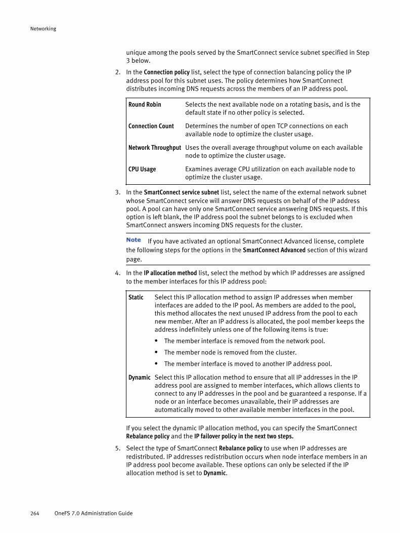
unique among the pools served by the SmartConnect service subnet specified in Step3 below.
2. In the Connection policy list, select the type of connection balancing policy the IPaddress pool for this subnet uses. The policy determines how SmartConnectdistributes incoming DNS requests across the members of an IP address pool.
Round Robin Selects the next available node on a rotating basis, and is thedefault state if no other policy is selected.
Connection Count Determines the number of open TCP connections on eachavailable node to optimize the cluster usage.
Network Throughput Uses the overall average throughput volume on each availablenode to optimize the cluster usage.
CPU Usage Examines average CPU utilization on each available node tooptimize the cluster usage.
3. In the SmartConnect service subnet list, select the name of the external network subnetwhose SmartConnect service will answer DNS requests on behalf of the IP addresspool. A pool can have only one SmartConnect service answering DNS requests. If thisoption is left blank, the IP address pool the subnet belongs to is excluded whenSmartConnect answers incoming DNS requests for the cluster.
If you have activated an optional SmartConnect Advanced license, completethe following steps for the options in the SmartConnect Advanced section of this wizardpage.
4. In the IP allocation method list, select the method by which IP addresses are assignedto the member interfaces for this IP address pool:
Static Select this IP allocation method to assign IP addresses when memberinterfaces are added to the IP pool. As members are added to the pool,this method allocates the next unused IP address from the pool to eachnew member. After an IP address is allocated, the pool member keeps theaddress indefinitely unless one of the following items is true:
l The member interface is removed from the network pool.
l The member node is removed from the cluster.
l The member interface is moved to another IP address pool.
Dynamic Select this IP allocation method to ensure that all IP addresses in the IPaddress pool are assigned to member interfaces, which allows clients toconnect to any IP addresses in the pool and be guaranteed a response. If anode or an interface becomes unavailable, their IP addresses areautomatically moved to other available member interfaces in the pool.
If you select the dynamic IP allocation method, you can specify the SmartConnectRebalance policy and the IP failover policy in the next two steps.
5. Select the type of SmartConnect Rebalance policy to use when IP addresses areredistributed. IP addresses redistribution occurs when node interface members in anIP address pool become available. These options can only be selected if the IPallocation method is set to Dynamic.
Networking
264 OneFS 7.0 Administration Guide

AutomaticFailback(default)
Automatically redistributes IP addresses. The automatic rebalanceis triggered by a change to one of the following items.
l Cluster membership.
l Cluster external network configuration.
l A Member network interface.
Manual Failback Does not redistribute IP addresses until you manually issue arebalance command through the command-line interface.
l This is the default policy that automatically redistributes IP addresses. Theautomatic rebalance is triggered by a change to one of the following items.
l :
6. The IP failover policy—also known as NFS failover—determines how to redistribute theIP addresses among remaining members of an IP address pool when one or moremembers are unavailable. In order to enable IP failover, you must first set the IPallocation method to Dynamic, and then select which type of IP failover policy to use:
Round Robin Selects the next available node on a rotating basis, and is thedefault state if no other policy is selected.
Connection Count Determines the number of open TCP connections on eachavailable node to optimize the cluster usage.
Network Throughput Uses the overall average throughput volume on each availablenode to optimize the cluster usage.
CPU Usage Examines average CPU utilization on each available node tooptimize the cluster usage.
7. Click Next to store the changes that you made to this wizard page.The Step 4 of 4 — IP Address Pool members dialog box appears.
What to do nextThis is the third of four steps required to configure an external network subnet. To savethe network configuration, you must complete each of the remaining steps. Forinformation on the next step, see Select the interface members for an IP address pool.
Select interface members for a new subnetYou can select which network interfaces belong to the IP address pool that belongs to theexternal network subnet.
Before you beginThis is the final of four steps that are required to configure a external network subnet on acluster by using the Subnet wizard. The choices available on this wizard page depend onthe types of external network interfaces of your Isilon cluster nodes.
1. In the Step 4 of 4 — IP Address Pool Members dialog box, select which Available interfaceson which nodes you want to assign to the current IP address pool, and then click theright arrow button.
You can also drag and drop the selected interfaces between the Available interfacestable and the Interfaces in current pool table.
Selecting an available interface for a node that has a Type designated Aggregationbonds together the external interfaces for the selected node. For information aboutNIC aggregation, refer to NIC aggregation.
Networking
Adding a subnet 265

In the case of aggregated links, choose the aggregation mode that corresponds to theswitch settings from the Aggregation mode drop-down.
Configuring link aggregation requires advanced knowledge of how toconfigure network switches. Consult your network switch documentation beforeconfiguring your cluster for link aggregation.
2. When you have finished assigning external network interfaces to the IP address pool,click Submit.The external subnet settings you configured by using the Subnet wizard appear onthe Edit Subnet page.
What to do nextYou can change the subnet configuration settings at any time without going through thefour-step wizard process. For more information, see Managing external client subnets.
Managing external client subnetsTo modify a subnet, you can go directly to any of the subnet settings that you want tochange.
You can modify the default external network subnet for your cluster, which wasconfigured during cluster installation by using the command-line Configuration wizard.You can also configure any new subnets you have added to the cluster after the initialsetup.
Modify external subnet settingsYou can modify the subnet for the external network.
Modifying an external network subnet that is in use can disable access to thecluster and the web administration interface. OneFS displays a warning if deleting asubnet will terminate communication between the cluster and the web administrationinterface.
1. Click Cluster Management > Network Configuration.
2. In the External Network Settings area, click the name of the subnet you want to modify.
3. In the Settings area, click Edit.
4. Modify the Basic subnet settings as needed.
Description A descriptive comment that can be up to 128 characters.
Netmask The subnet mask for the network interface. This field appears onlyfor IPv4 subnets.
MTU The maximum size of the transmission units the cluster uses innetwork communication. Any numerical value is allowed, butmight not be compatible with your network. Common settings are1500 (standard frames) and 9000 (jumbo frames).
Gateway address The IP address of the gateway server through which the clustercommunicates with systems outside of the subnet.
Gateway priority The priority of the subnet's gateway for nodes that are assigned tomore than one subnet. Only one default gateway can be
Networking
266 OneFS 7.0 Administration Guide
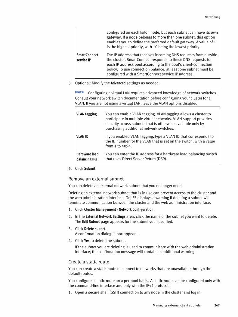
configured on each Isilon node, but each subnet can have its owngateway. If a node belongs to more than one subnet, this optionenables you to define the preferred default gateway. A value of 1is the highest priority, with 10 being the lowest priority.
SmartConnectservice IP
The IP address that receives incoming DNS requests from outsidethe cluster. SmartConnect responds to these DNS requests foreach IP address pool according to the pool's client-connectionpolicy. To use connection balance, at least one subnet must beconfigured with a SmartConnect service IP address.
5. Optional: Modify the Advanced settings as needed.
Configuring a virtual LAN requires advanced knowledge of network switches.Consult your network switch documentation before configuring your cluster for aVLAN. If you are not using a virtual LAN, leave the VLAN options disabled.
VLAN tagging You can enable VLAN tagging. VLAN tagging allows a cluster toparticipate in multiple virtual networks. VLAN support providessecurity across subnets that is otherwise available only bypurchasing additional network switches.
VLAN ID If you enabled VLAN tagging, type a VLAN ID that corresponds tothe ID number for the VLAN that is set on the switch, with a valuefrom 1 to 4094.
Hardware loadbalancing IPs
You can enter the IP address for a hardware load balancing switchthat uses Direct Server Return (DSR).
6. Click Submit.
Remove an external subnetYou can delete an external network subnet that you no longer need.
Deleting an external network subnet that is in use can prevent access to the cluster andthe web administration interface. OneFS displays a warning if deleting a subnet willterminate communication between the cluster and the web administration interface.
1. Click Cluster Management > Network Configuration.
2. In the External Network Settings area, click the name of the subnet you want to delete.The Edit Subnet page appears for the subnet you specified.
3. Click Delete subnet.A confirmation dialogue box appears.
4. Click Yes to delete the subnet.
If the subnet you are deleting is used to communicate with the web administrationinterface, the confirmation message will contain an additional warning.
Create a static routeYou can create a static route to connect to networks that are unavailable through thedefault routes.
You configure a static route on a per-pool basis. A static route can be configured only withthe command-line interface and only with the IPv4 protocol.
1. Open a secure shell (SSH) connection to any node in the cluster and log in.
Networking
Managing external client subnets 267

2. Create a static route by running the following command: isi networks modifypool --name <subnetname>:<poolname> --add-static-routes <subnet>/<netmask>-<gateway>
The system displays output similar to the following example:
Modifying pool 'subnet0:pool0':
Saving: OK
3. To ensure that the static route was created, run the following command: isinetworks ls pools -v.
Remove a static routeYou can remove static routes.
1. Open a secure shell (SSH) connection to any node in the cluster and log in.
2. Remove a static route by running the following command: isi networks modifypool --name <subnetname>:<poolname> --remove-static-routes <subnet>/<netmask>-<gateway>
The system displays output similar to the following example:
Modifying pool 'subnet0:pool0':
Saving: OK
3. To ensure that the static route was created, run the following command: isinetworks ls pools -v.
Enable or disable VLAN taggingYou can configure a cluster to participate in multiple virtual private networks, also knownas virtual LANs or VLANs. You can also configure a VLAN when creating a subnet using theSubnet wizard.
1. Click Cluster Management > Network Configuration.
2. In the External Network Settings area, click the name of the subnet that contains the IPaddress pool that you want to add interface members to.
3. In the Settings area for the subnet, click Edit.
4. In the VLAN tagging list, select Enabled or Disabled.If you select Enabled, proceed to the next step. If you select Disabled, proceed to Step6.
5. In the VLAN ID field, type a number between 2 and 4094 that corresponds to the VLANID number set on the switch.
6. Click Submit.
Managing IP address poolsYou can configure IP address pools to control what network interfaces and IP addressesare attached to different subnets. IP address pools allow you to customize how clientsaccess the cluster.
Add an IP address poolYou can use the web interface to add an IP address pool.
1. Click Cluster Management > Network Configuration.
Networking
268 OneFS 7.0 Administration Guide

2. Click the name of the subnet you wan too ad an IP address pool to.
3. In the IP Address Pools area, click Add pool by the I.
4. The IP Address Pool wizard appears. For more information on the three steps of thewizard, see Add an IP address pool to a new subnet, Configure SmartConnect settingsfor a new subnet and Select interface members for a new subnet.
Modify an IP address poolYou can use the web interface to modify IP address pool settings.
1. Click Cluster Management > Network Configuration.
2. Click the name of the subnet containing the pool you want to modify.
3. In the Basic Settings area, click Edit for the IP address pool you want to modify.The Configure IP Pool page appears.
4. For more information, see Add an IP address pool to a new subnet.
Delete an IP address poolYou can use the web interface to delete IP address pool settings.
1. Click Cluster Management > Network Configuration.
2. Click the name of the subnet containing the pool you want to delete.
3. Click Delete pool by the pool you want to delete.
Modify a SmartConnect zoneYou can modify the settings of a SmartConnect zone that you created for an externalnetwork subnet using the Subnet wizard.
1. Click Cluster Management > Network Configuration.
2. Click the name of the external network subnet that contains the SmartConnect zoneyou want to modify.
3. In the SmartConnect settings area for the pool containing the SmartConnect settingsyou want to modify, click Edit.
4. Modify any SmartConnect settings, and then click Submit.
For more information, see Configure SmartConnect settings for a new subnet .
Disable a SmartConnect zoneYou can remove a SmartConnect zone from an external network subnet.
1. Click Cluster Management > Network Configuration.
2. Click the name of the external network subnet that contains the SmartConnect zoneyou want to disable.
3. In the SmartConnect settings area for the pool containing the SmartConnect zone youwant to delete, click Edit.
4. To disable the SmartConnect zone, delete the name of the SmartConnect zone fromthe Zone name field and leave the field blank.
5. Click Submit to disable the SmartConnect zone.
For more information, see Configure SmartConnect settings for a new subnet .
Networking
Managing IP address pools 269

Configure IP failoverYou can configure IP failover to reassign an IP address from an unavailable node to afunctional node, which enables clients to continue communicating with the cluster, evenafter a node becomes unavailable.
1. Click Cluster Management > Network Configuration
2. In the External Network Settings area, click the name of the subnet you want to set up IPfailover for.
3. Expand the area of the pool you want to modify and click Edit in the SmartConnectSettings area.
4. Optional: In the Zone name field, you can enter a 128-character name for the zone.
5. In the Connection Policy list, select a balancing policy:
Round Robin Selects the next available node on a rotating basis, and is thedefault state if no other policy is selected.
Connection Count Determines the number of open TCP connections on eachavailable node to optimize the cluster usage.
Network Throughput Uses the overall average throughput volume on each availablenode to optimize the cluster usage.
CPU Usage Examines average CPU utilization on each available node tooptimize the cluster usage.
6. If you purchased a license for SmartConnect Advanced, you will also have access tothe following lists:
u IP allocation method — This setting determines how IP addresses are assigned toclients. Select either Dynamic or Static.
u Rebalance Policy — This setting defines the client redirection policy for when a nodebecomes unavailable. The IP allocation list must be set to Dynamic in order for rebalancepolicy options to be selected.
u IP failover policy — This setting defines the client redirection policy for when an IPaddress is unavailable.
Allocate IP addresses to accommodate new nodesYou can expand capacity by adding new nodes to your Isilon cluster.
After the hardware installation is complete, you can allocate IP addresses for a new nodeon one of the cluster's existing external network subnets, and then add the node'sexternal interfaces to the subnet's IP address pool.
You can also use network provisioning rules to automate the process of configuring theexternal network interfaces for new nodes when they are added to a cluster, although youmay still need to allocate more IP addresses for the new nodes, depending on how manyare already configured.
1. Click Cluster Management > Network Configuration.
2. In the External Network Settings area, click the name of the subnet that contains the IPaddress pool that you want to allocate more IP addresses to in order to accommodatethe new nodes.
3. In the Basic settings area, click Edit.
Networking
270 OneFS 7.0 Administration Guide

4. Click New to add a new IP address range using the Low IP and High IP fields. or click therespective value in either the Low IP or High IP columns and type a new beginning orending IP address.
5. Click Submit.
6. In the Pool members area, click Edit.
7. In the Available Interfaces table, select one or more interfaces for the newly addednode, and then click the right arrow button to move the interfaces into the Interfaces incurrent pool table.
8. Click Submit to assign the new node interfaces to the IP address pool.
Managing IP address pool interface membersYou can assign interfaces to specific IP address pools.
Available interfaces are presented as all possible combinations of each interface on eachnode in the cluster, as well as NIC aggregation for each interface type on each node in thecluster.
Modify the interface members of a subnetYou can use the web interface to modify interface member settings.
1. Click Cluster Management > Network Configuration.
2. In the External Network Settings area, click the subnet containing the interfacemembers you want to modify.
3. Click Edit next to the Pool members area.
For more information, please see Select interface members for a new subnet.
Remove interface members from an IP address poolYou can use the web interface to remove interface members from an IP address pool.
1. Click Cluster Management > Network Configuration.
2. In the External Network Settings area, click the name of the subnet containing the IPaddress pool that you want to remove the interface member(s) for.
3. In the Pool members area, click Edit.
4. Remove a node's interface from the IP address pool by clicking the node's name inthe Interfaces in current pool column, and then click the left arrow button. You can alsodrag and drop node interfaces between the Available Interfaces list and the Interfaces incurrent poolcolumn.
5. When you have finished removing node interfaces from the IP address pool, clickSubmit.
For more information, please see Select interface members for a new subnet.
Configure NIC aggregationYou can configure cluster IP address pools to use NIC aggregation.
This procedure describes how to configure network interface card (NIC) aggregation for anIP address pool belonging to an existing subnet. You can also configure NIC aggregationwhile configuring an external network subnet using the Subnet wizard.
Configuring NIC aggregation means that multiple, physical external network interfaces ona node are combined into a single logical interface. If a node has two external GigabitEthernet interfaces, both will be aggregated. On a node with both Gigabit and 10 Gigabit
Networking
Managing IP address pool interface members 271

Ethernet interfaces, both types of interfaces can be aggregated, but only with interfacesof the same type. NIC aggregation cannot be used with mixed interface types.
An external interface for a node cannot be used by an IP address pool in both anaggregated configuration and an individual interface. You must remove the individualinterface for a node from the Interfaces in current pool table before configuring anaggregated NIC. Otherwise, the web administration interface displays an error messagewhen you click Submit.
Configuring link aggregation requires advanced knowledge of network switches.Consult your network switch documentation before configuring your cluster for NICaggregation.
Before you beginYou must enable NIC aggregation on the cluster before you can enable NIC aggregationon the switch. If the cluster is configured but the switch is not configured, then the clustercan continue to communicate. If the switch is configured, but the cluster is notconfigured, the cluster cannot communicate, and you are unable to configure the clusterfor NIC aggregation.
1. Click Cluster Management > Network Configuration.
2. In the External Network Settings area, click the name of the subnet that contains the IPaddress pool that you want to add aggregated interface members to.
3. In the Pool members area, click Edit.
In the case of multiple IP address pools, expand the pool that you want to add theaggregated interfaces to, and then click Edit in the Pool members area.
4. In the Available interfaces table, click the aggregated interface for the node, which isindicated by a listing of AGGREGATION in the Type column.For example, if you want to aggregate the network interface card for Node 2 of thecluster, click the interface named ext-agg, Node 2 under Available interfaces, and thenclick the right-arrow button to move the aggregated interface to the Interfaces in currentpool table.
5. From the Aggregation mode drop-down, select the appropriate aggregation mode thatcorresponds to the network switch settings.
Consult your network switch documentation for supported NIC aggregationmodes.
OneFS supports the following NIC aggregation modes:
Link AggregationControl Protocol (LACP)
Supports the IEEE 802.3ad Link Aggregation Control Protocol(LACP). This method is recommended for switches thatsupport LACP and is the default mode for new pools.
Legacy FastEtherChannel (FEC)mode
This method is compatible with aggregated configurations inearlier versions of OneFS.
Etherchannel (FEC) This method is the newer implementation of the Legacy FECmode.
Active / PassiveFailover
This method transmits all data transmits through the masterport, which is the first port in the aggregated link. The next
Networking
272 OneFS 7.0 Administration Guide

active port in an aggregated link takes over if the master portis unavailable.
Round-Robin Tx This method balances outbound traffic across all active portsin the aggregated link and accepts inbound traffic on anyport.
6. Click Submit.
Remove an aggregated NIC from an IP address pool
You can remove an aggregated NIC configuration from an IP address pool if your networkenvironment has changed. However, you must first replace the aggregated setting withsingle-NIC settings in order for the node to continue supporting network traffic.
1. Click Cluster Management > Network Configuration.
2. In the External Network Settings area, click the name of the subnet that contains the IPaddress pol with the NIC aggregation settings you want to remove.
3. In the Pool members area, click Edit.
4. Select the name of the aggregated NIC for the node that you want to remove in theInterfaces in current pool table, and then click the left arrow button to move the nameinto the Available interfaces table.
5. Select one or more individual interfaces for the node in the Available interfaces table,and then click the right arrow button to move the interfaces into the Interfaces in currentpool table.
6. When you have completed modifying the node interface settings, click Submit.
Move nodes between IP address poolsYou can move nodes between IP address pools in the event of a network reconfigurationor installation of a new network switch.
The process of moving nodes between IP address pools involves creating a new IPaddress pool and then assigning it to the nodes so that they are temporarily servicingmultiple subnets. After testing that the new IP address pool is working correctly, the oldIP address pool can safely be deleted.
1. Create a new IP address pool with the interfaces belonging to the nodes you want tomove. For more information, see Add an IP address pool.
2. Verify that the new IP address pool functions properly by connecting to the nodes youwant to move with IP addresses from the new pool.
3. Delete the old IP address pool. For more information, see Delete an IP address pool.
Reassign a node to another external subnetYou can move a node interface to a different subnet.
Nodes can be reassigned to other subnets.
1. Click Cluster Management > Network Configuration.
2. In the External Settings area, click the subnet containing the node that you want tomodify.
3. In the IP Address Pools area, click Edit next to the Pool members area.
Networking
Managing IP address pool interface members 273

4. Reassign the interface members that you want to move by dragging and droppingthem from one column to other, or by clicking on an interface member and using theleft arrow and right arrow buttons.
NIC and LNI aggregation optionsNetwork interface card (NIC) and logical network interface (LNI) mapping options can beconfigured for aggregation.
The following list provides guidelines for interpreting the aggregation options.
u Nodes support multiple network card configurations.
u LNI numbering corresponds to the physical positioning of the NIC ports as found onthe back of the node, and LNI mappings are numbered from left to right.
u Aggregated LNIs are listed in the order in which they are aggregated at the time theyare created.
u NIC names correspond to the network interface name as shown in command-lineinterface tools such as ifconfig and netstat.
LNI NIC Aggregated LNI Aggregated NIC Aggregated NIC(Legacy FECmode
- - - - -ext-1
ext-2
em0
em1
ext-agg = ext-1 +ext-2
lagg0 fec0
ext-1
ext-2
ext-3
ext-4
em2
em3
em0
em1
ext-agg = ext-1 +ext-2
ext-agg-2 = ext-3+ ext-4
ext-agg-3 = ext-3+ ext-4 + ext-1 +ext-2
lagg0
lagg1
lagg2
fec0
fec1
fec2
ext-1
ext-2
10gige-1
10gige-1
em0
em1
cxgb0
cxgb1
ext-agg = ext-1 +ext-2
10gige-agg-1 =10gige-1 +10gige-2
lagg0
lagg1
fec0
fec1
Configure DNS settingsYou can configure the domain name servers and DNS search list that the cluster uses toresolve host names.
1. Click Cluster Management > Networking Configuration.
2. In the DNS Settings area, click Edit.
3. In the Domain name server(s) field, type the IP address of the domain name server thatyou want to add. This is the domain name server address that the cluster uses toanswer all DNS requests.
You can specify domain name server addresses in IPv4 or IPv6 format.
4. In the DNS search list field, enter the local domain name.
Networking
274 OneFS 7.0 Administration Guide
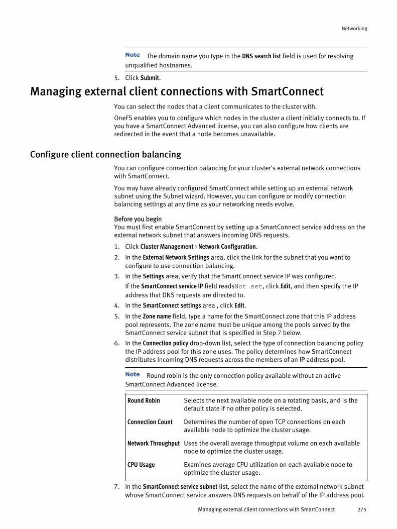
The domain name you type in the DNS search list field is used for resolvingunqualified hostnames.
5. Click Submit.
Managing external client connections with SmartConnectYou can select the nodes that a client communicates to the cluster with.
OneFS enables you to configure which nodes in the cluster a client initially connects to. Ifyou have a SmartConnect Advanced license, you can also configure how clients areredirected in the event that a node becomes unavailable.
Configure client connection balancingYou can configure connection balancing for your cluster's external network connectionswith SmartConnect.
You may have already configured SmartConnect while setting up an external networksubnet using the Subnet wizard. However, you can configure or modify connectionbalancing settings at any time as your networking needs evolve.
Before you beginYou must first enable SmartConnect by setting up a SmartConnect service address on theexternal network subnet that answers incoming DNS requests.
1. Click Cluster Management > Network Configuration.
2. In the External Network Settings area, click the link for the subnet that you want toconfigure to use connection balancing.
3. In the Settings area, verify that the SmartConnect service IP was configured.
If the SmartConnect service IP field readsNot set, click Edit, and then specify the IPaddress that DNS requests are directed to.
4. In the SmartConnect settings area , click Edit.
5. In the Zone name field, type a name for the SmartConnect zone that this IP addresspool represents. The zone name must be unique among the pools served by theSmartConnect service subnet that is specified in Step 7 below.
6. In the Connection policy drop-down list, select the type of connection balancing policythe IP address pool for this zone uses. The policy determines how SmartConnectdistributes incoming DNS requests across the members of an IP address pool.
Round robin is the only connection policy available without an activeSmartConnect Advanced license.
Round Robin Selects the next available node on a rotating basis, and is thedefault state if no other policy is selected.
Connection Count Determines the number of open TCP connections on eachavailable node to optimize the cluster usage.
Network Throughput Uses the overall average throughput volume on each availablenode to optimize the cluster usage.
CPU Usage Examines average CPU utilization on each available node tooptimize the cluster usage.
7. In the SmartConnect service subnet list, select the name of the external network subnetwhose SmartConnect service answers DNS requests on behalf of the IP address pool.
Networking
Managing external client connections with SmartConnect 275

A pool can have only one SmartConnect service answering DNS requests. If thisoption is left blank, the IP address pool that the SmartConnect service belongs to isexcluded when SmartConnect answers incoming DNS requests for the cluster.
If you have purchased a license for the SmartConnect Advanced module, completethe following steps in the SmartConnect Advanced area.
8. In the IP allocation method list, select the method by which IP addresses are assignedto the member interfaces for this IP address pool.
Client connection settingsThe OneFS SmartConnect module balances client connections across all nodes within anIsilon cluster, or across selected nodes.
1. Click Cluster Management > Network Configuration
2. In the External Network Settings area, next to the SmartConnect settings section, clickEdit.
3. Optional: In the Zone name field, enter a 128-character name for the zone.
4. In the Connection policy list, select a balancing policy.
Round robin is the only connection policy available without an activeSmartConnect Advanced license.
Round Robin Selects the next available node on a rotating basis, and is thedefault state if no other policy is selected.
Connection Count Determines the number of open TCP connections on eachavailable node to optimize the cluster usage.
Network Throughput Uses the overall average throughput volume on each availablenode to optimize the cluster usage.
CPU Usage Examines average CPU utilization on each available node tooptimize the cluster usage.
5. In the SmartConnect service subnet field, type the subnet used for this policy.
6. Click Submit.
Managing network interface provisioning rulesYou can automate the configuration of external network interfaces for new nodes whenthey are added to a cluster with provisioning rules.
When you initially configure a cluster, OneFS creates a default provisioning rule calledrule0. This provisioning rule adds an external network interface to the default subnet anddefault IP address pools of a newly added node. You can modify this default provisioningrule as needed and add more provisioning rules as needed. Provisioning rules specifyhow new nodes are configured when they are added to a cluster.
For example, you can create one provisioning rule that configures new Isilon storagenodes, and another rule that configures new accelerator nodes. Similarly, you can alsocreate provisioning rules by model or type, such as the Isilon X-series storage andaccelerator nodes.
After the provisioning rules are configured, new nodes are evaluated and configuredaccording to the provisioning rules. If the type of the new node (storage-I, accelerator-I,storage, accelerator, or backup-accelerator) matches the type defined in a rule, the newnode's interface name is added to the subnet and the IP address pool specified in the
Networking
276 OneFS 7.0 Administration Guide
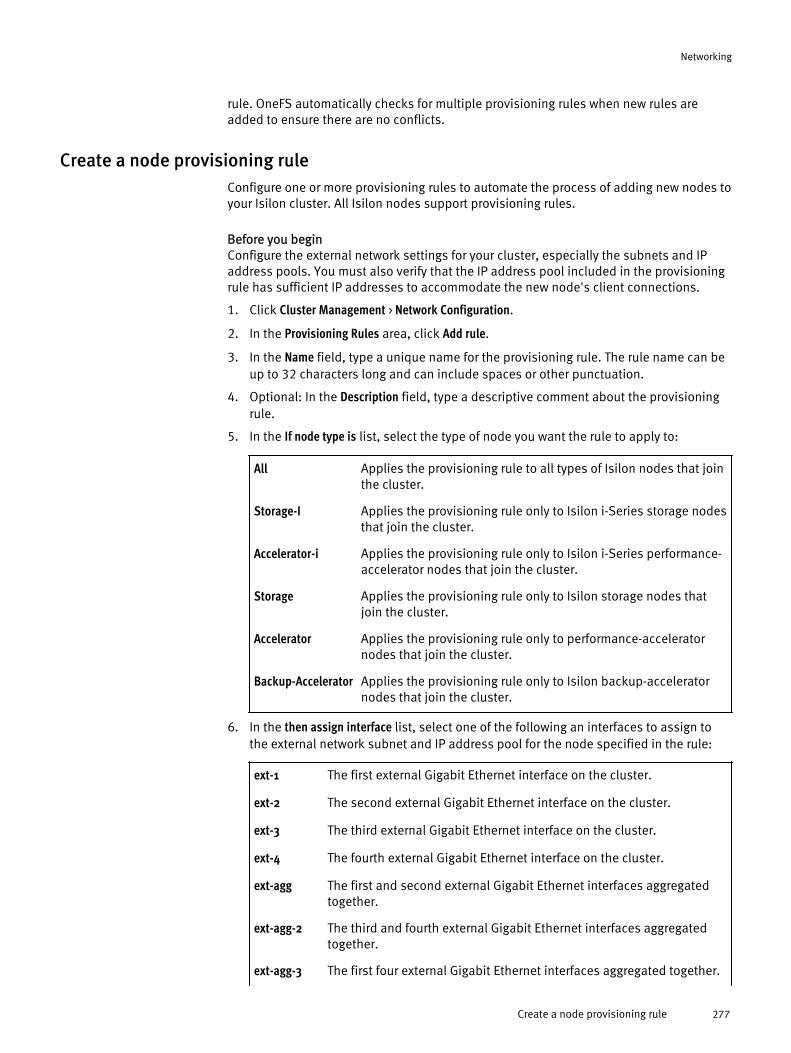
rule. OneFS automatically checks for multiple provisioning rules when new rules areadded to ensure there are no conflicts.
Create a node provisioning ruleConfigure one or more provisioning rules to automate the process of adding new nodes toyour Isilon cluster. All Isilon nodes support provisioning rules.
Before you beginConfigure the external network settings for your cluster, especially the subnets and IPaddress pools. You must also verify that the IP address pool included in the provisioningrule has sufficient IP addresses to accommodate the new node's client connections.
1. Click Cluster Management > Network Configuration.
2. In the Provisioning Rules area, click Add rule.
3. In the Name field, type a unique name for the provisioning rule. The rule name can beup to 32 characters long and can include spaces or other punctuation.
4. Optional: In the Description field, type a descriptive comment about the provisioningrule.
5. In the If node type is list, select the type of node you want the rule to apply to:
All Applies the provisioning rule to all types of Isilon nodes that jointhe cluster.
Storage-I Applies the provisioning rule only to Isilon i-Series storage nodesthat join the cluster.
Accelerator-i Applies the provisioning rule only to Isilon i-Series performance-accelerator nodes that join the cluster.
Storage Applies the provisioning rule only to Isilon storage nodes thatjoin the cluster.
Accelerator Applies the provisioning rule only to performance-acceleratornodes that join the cluster.
Backup-Accelerator Applies the provisioning rule only to Isilon backup-acceleratornodes that join the cluster.
6. In the then assign interface list, select one of the following an interfaces to assign tothe external network subnet and IP address pool for the node specified in the rule:
ext-1 The first external Gigabit Ethernet interface on the cluster.
ext-2 The second external Gigabit Ethernet interface on the cluster.
ext-3 The third external Gigabit Ethernet interface on the cluster.
ext-4 The fourth external Gigabit Ethernet interface on the cluster.
ext-agg The first and second external Gigabit Ethernet interfaces aggregatedtogether.
ext-agg-2 The third and fourth external Gigabit Ethernet interfaces aggregatedtogether.
ext-agg-3 The first four external Gigabit Ethernet interfaces aggregated together.
Networking
Create a node provisioning rule 277

ext-agg-4 All six Gigabit Ethernet interfaces aggregated together.
10gige-1 The first external 10 Gigabit Ethernet interface on the cluster.
10gige-2 The second external 10 Gigabit Ethernet interface on the cluster.
10gige-agg-1 The first and second external 10 Gigabit Ethernet interfaces aggregatedtogether.
7. In the Subnet list, select the external subnet that the new node will join.
8. In the Pool list, select the IP address pool that belongs to the subnet that should beused by the new node.
9. Click Submit.
Modify a node provisioning ruleYou can modify a node provisioning rules.
1. Click Cluster Configuration > Network Configuration.
2. In the Provisioning Rules area, click the name of the rule you want to modify.
3. Modify the provisioning rule settings as needed.
4. When you have finished modifying the provisioning rule, click Submit.
Delete a node provisioning ruleYou can delete a provisioning rule that is no longer necessary.
1. Click Cluster Management > Network Configuration.
2. In the Provisioning Rules area, click Delete next to the rule you want to delete.A confirmation dialog box appears.
3. Click Yes to delete the rule, or click No to keep the rule.
Networking
278 OneFS 7.0 Administration Guide
CHAPTER 14
Hadoop
Hadoop is a flexible, open-source framework for large-scale distributed computation.
The OneFS file system can be configured for native support of the Hadoop Distributed FileSystem (HDFS) protocol, enabling your cluster to participate in a Hadoop system.
HDFS integration requires a separate license. To obtain additional information or toactivate HDFS support for your EMC Isilon cluster, contact your EMC Isilon salesrepresentative.
u Hadoop support overview....................................................................................280u Hadoop cluster integration..................................................................................280u Managing HDFS...................................................................................................280u Configure the HDFS protocol................................................................................280u Create a local user...............................................................................................282u Enable or disable the HDFS service......................................................................282
Hadoop 279

Hadoop support overviewAn HDFS implementation adds HDFS to the list of protocols that can be used to accessthe OneFS file system. Implementing HDFS on an Isilon cluster does not create a separateHDFS file system. The cluster can continue to be accessed through NFS, SMB, FTP, andHTTP.
The HDFS implementation from Isilon is a lightweight protocol layer between the OneFSfile system and HDFS clients. Unlike with a traditional HDFS implementation, files arestored in the standard POSIX-compatible file system on an Isilon cluster. This means filescan be accessed by the standard protocols that OneFS supports, such as NFS, SMB, FTP,and HTTP as well as HDFS.
Files that will be processed by Hadoop can be loaded by using standard Hadoopmethods, such as hadoop fs -put, or they can be copied by using an NFS or SMBmount and accessed by HDFS as though they were loaded by Hadoop methods. Also, filesloaded by Hadoop methods can be read with an NFS or SMB mount.
The supported versions of Hadoop are as follows:
u Apache Hadoop 0.20.203.0
u Apache Hadoop 0.20.205
u Cloudera (CDH3 Update 3)
u Greenplum HD 1.1
Hadoop cluster integrationTo enable native HDFS support in OneFS, you must integrate the Isilon cluster with acluster of Hadoop compute nodes.
This process requires configuration of the Isilon cluster as well as each Hadoop computenode that needs access to the cluster.
Managing HDFSTo keep the HDFS service performing efficiently on a OneFS cluster, you will need to befamiliar with the user and system configuration options available as part of an HDFSimplementation.
There are two different methods that you can use to manage an HDFS implementation:u Hadoop client machines are configured directly through their Hadoop installation
directory.
u A secure shell (SSH) connection to a node in the Isilon cluster is used to configure theHDFS service.
Configure the HDFS protocolYou can specify which HDFS distribution to use, and you can set the logging level, theroot path, the Hadoop block size, and the number of available worker threads.
You configure HDFS by running the isi hdfs command in the OneFS command-lineinterface.
1. Open a secure shell (SSH) connection to any node in the cluster and log in by usingthe root account.
You can combine multiple options with a single isi hdfs command. Forcommand usage and syntax, run the isi hdfs -h command.
Hadoop
280 OneFS 7.0 Administration Guide
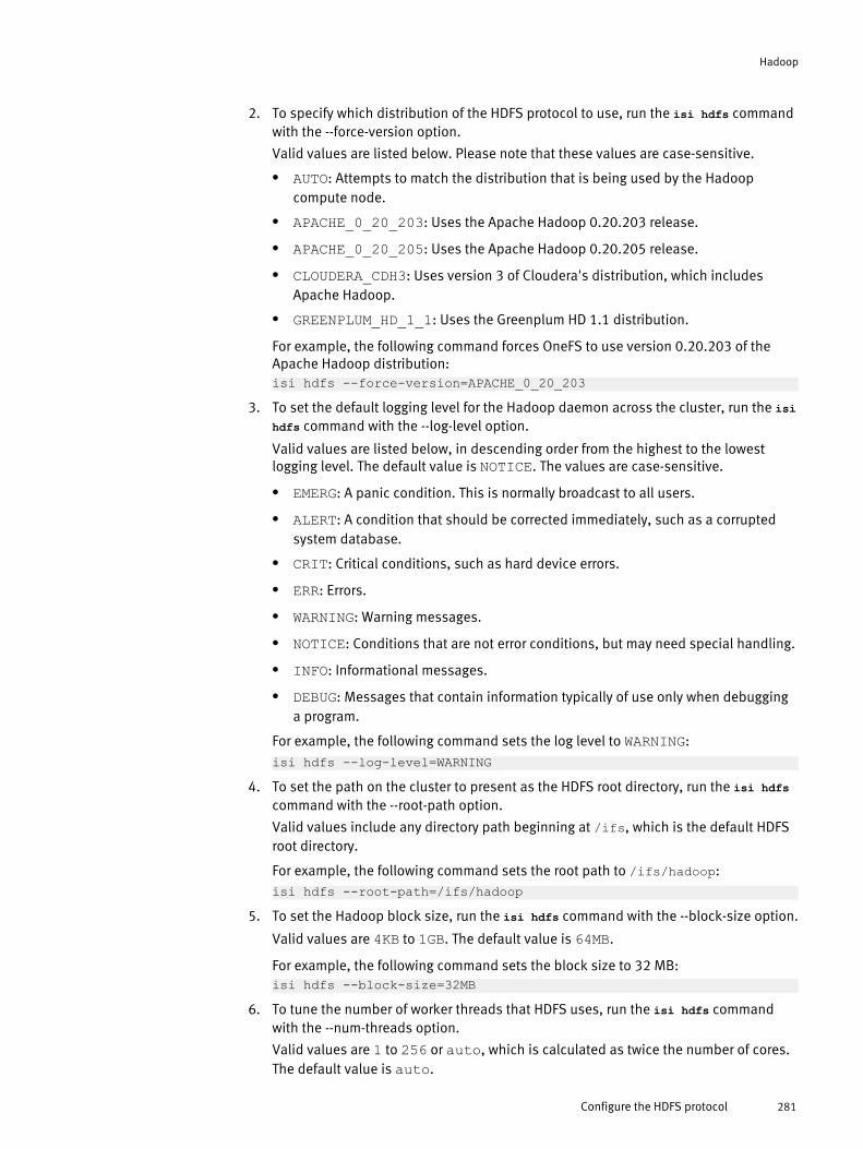
2. To specify which distribution of the HDFS protocol to use, run the isi hdfs commandwith the --force-version option.
Valid values are listed below. Please note that these values are case-sensitive.
l AUTO: Attempts to match the distribution that is being used by the Hadoopcompute node.
l APACHE_0_20_203: Uses the Apache Hadoop 0.20.203 release.
l APACHE_0_20_205: Uses the Apache Hadoop 0.20.205 release.
l CLOUDERA_CDH3: Uses version 3 of Cloudera's distribution, which includesApache Hadoop.
l GREENPLUM_HD_1_1: Uses the Greenplum HD 1.1 distribution.
For example, the following command forces OneFS to use version 0.20.203 of theApache Hadoop distribution:isi hdfs --force-version=APACHE_0_20_203
3. To set the default logging level for the Hadoop daemon across the cluster, run the isihdfs command with the --log-level option.
Valid values are listed below, in descending order from the highest to the lowestlogging level. The default value is NOTICE. The values are case-sensitive.
l EMERG: A panic condition. This is normally broadcast to all users.
l ALERT: A condition that should be corrected immediately, such as a corruptedsystem database.
l CRIT: Critical conditions, such as hard device errors.
l ERR: Errors.
l WARNING: Warning messages.
l NOTICE: Conditions that are not error conditions, but may need special handling.
l INFO: Informational messages.
l DEBUG: Messages that contain information typically of use only when debugginga program.
For example, the following command sets the log level to WARNING:isi hdfs --log-level=WARNING
4. To set the path on the cluster to present as the HDFS root directory, run the isi hdfscommand with the --root-path option.
Valid values include any directory path beginning at /ifs, which is the default HDFSroot directory.
For example, the following command sets the root path to /ifs/hadoop:isi hdfs --root-path=/ifs/hadoop
5. To set the Hadoop block size, run the isi hdfs command with the --block-size option.
Valid values are 4KB to 1GB. The default value is 64MB.
For example, the following command sets the block size to 32 MB:isi hdfs --block-size=32MB
6. To tune the number of worker threads that HDFS uses, run the isi hdfs commandwith the --num-threads option.
Valid values are 1 to 256 or auto, which is calculated as twice the number of cores.The default value is auto.
Hadoop
Configure the HDFS protocol 281

For example, the following command specifies 8 worker threads:
isi hdfs --num-threads=87. To allocate IP addresses from an IP address pool, run isi hdfs with the --add-ip-pool
option.
Valid values are in the form <subnet>:<pool>.
For example, the following command allocates IP addresses from a pool named"pool2," which is in the "subnet0" subnet:isi hdfs --add-ip-pool=subnet0:pool2
Create a local userTo access files on OneFS by using the HDFS protocol, you must first create a local Hadoopuser that maps to a user on a Hadoop client.
1. Open a secure shell (SSH) connection to any node in the cluster and log in by usingthe root user account.
2. At the command prompt, run the isi auth users create command to create a localuser.
For example, isi auth users create --name="user1".
Enable or disable the HDFS serviceThe HDFS service, which is enabled by default after you activate an HDFS license, can beenabled or disabled by running the isi services command.
1. Open a secure shell (SSH) connection to any node in the cluster and log in by usingthe root user account.
2. At the command prompt, run the isi service command to enable or disable theHDFS service, isi_hdfs_d.l To enable the HDFS service, run the following command:
isi services isi_hdfs_d enablel To disable the HDFS service, run the following command:
isi services isi_hdfs_d disable
Hadoop
282 OneFS 7.0 Administration Guide

CHAPTER 15
Antivirus
OneFS enables you to scan the file system for computer viruses and other security threatson an Isilon cluster by integrating with third-party scanning services through the InternetContent Adaptation Protocol (ICAP). OneFS sends files through ICAP to a server runningthird-party antivirus scanning software. These servers are referred to as ICAP servers.ICAP servers scan files for viruses.
After an ICAP server scans a file, it informs OneFS of whether the file is a threat. If a threatis detected, OneFS informs system administrators by creating an event, displaying nearreal-time summary information, and documenting the threat in an antivirus scan report.You can configure OneFS to request that ICAP servers attempt to repair infected files. Youcan also configure OneFS to protect users against potentially dangerous files bytruncating or quarantining infected files.
Before OneFS sends a file to be scanned, it ensures that the scan is not redundant. If afile has not been modified, OneFS will not send the file to be scanned unless the virusdatabase on the ICAP server has been updated since the last scan.
u On-access scanning............................................................................................284u Antivirus policy scanning.....................................................................................284u Individual file scanning.......................................................................................284u Antivirus scan reports.........................................................................................285u ICAP servers........................................................................................................285u Supported ICAP servers.......................................................................................285u Anitvirus threat responses...................................................................................286u Configuring global antivirus settings...................................................................287u Managing ICAP servers........................................................................................289u Create an antivirus policy....................................................................................290u Managing antivirus policies.................................................................................291u Managing antivirus scans....................................................................................291u Managing antivirus threats..................................................................................292u Managing antivirus reports..................................................................................293
Antivirus 283

On-access scanningYou can configure OneFS to send files to be scanned before they are opened, after theyare closed, or both. Sending files to be scanned after they are closed is faster but lesssecure. Sending files to be scanned before they are opened is slower but more secure.
If OneFS is configured to ensure that files are scanned after they are closed, when a usercreates or modifies a file on the cluster, OneFS queues the file to be scanned. OneFS thensends the file to an ICAP server to be scanned when convenient. In this configuration,users can always access their files without any delay. However, it is possible that after auser modifies or creates a file, a second user might request the file before the file isscanned. If a virus was introduced to the file from the first user, the second user will beable to access the infected file. Also, if an ICAP server is unable to scan a file, the file willstill be accessible to users.
If OneFS ensures that files are scanned before they are opened, when a user attempts todownload a file from the cluster, OneFS first sends the file to an ICAP server to bescanned. The file is not sent to the user until the scan is complete. Scanning files beforethey are opened is more secure than scanning files after they are closed, because userscan access only scanned files. However, scanning files before they are opened requiresusers to wait for files to be scanned. You can also configure OneFS to deny access to filesthat cannot be scanned by an ICAP server, which can increase the delay. For example, ifno ICAP servers are available, users will not be able to access any files until the ICAPservers become available again.
If you configure OneFS to ensure that files are scanned before they are opened, it isrecommended that you also configure OneFS to ensure that files are scanned after theyare closed. Scanning files as they are both opened and closed will not necessarilyimprove security, but it will usually improve data availability when compared to scanningfiles only when they are opened. If a user wants to access a file, the file may have alreadybeen scanned after the file was last modified, and will not need to be scanned againprovided that the ICAP server database has not been updated since the last scan.
Antivirus policy scanningYou can create antivirus scanning policies that send files that are contained in a specificdirectory to be scanned. Antivirus policies can be run manually at any time, or configuredto run according to a schedule.
Antivirus policies target a specific directory on the cluster. You can prevent an antiviruspolicy from sending certain files within the specified root directory based on the size,name, or extension of the file. Antivirus policies do not target snapshots. Only on-accessscans include snapshots. Antivirus scans are handled by the OneFS job engine, andfunction the same as any system job.
Individual file scanningYou can send a specific file to an ICAP server to be scanned at any time.
For example, if a virus is detected in a file but the ICAP server is unable to repair it. Youcan send the file to the ICAP server after the virus database had been updated, and theICAP server might be able to repair the file. You can also use individual file scanning toensure that the cluster and ICAP server have been properly configured to interact witheach other.
Antivirus
284 OneFS 7.0 Administration Guide

Antivirus scan reportsOneFS generates a report about antivirus scans. Each time that an antivirus policy is run,OneFS generates a report for that policy. OneFS also generates a report every 24 hoursthat includes all on-access scans that occurred during the day.
Antivirus scan reports contain the following information:
u The time that the scan started.
u The time that the scan ended.
u The total number of files scanned.
u The total size of the files scanned.
u The total network traffic sent.
u The network throughput that was consumed by virus scanning.
u Whether the scan succeeded.
u The total number of infected files detected.
u The names of infected files.
u The threats associated with infected files.
u How OneFS responded to detected threats.
u The name and IP address of the user that triggered the scan.This information is not included in reports triggered by antivirus scan policies.
ICAP serversThe number of ICAP servers that are required to support an Isilon cluster depends on howvirus scanning is configured, the amount of data a cluster processes, and the processingpower of the ICAP servers.
If you intend on scanning files only according to antivirus scan policies, it isrecommended that you have a minimum of two ICAP servers for a cluster. If you intend onscanning files on-access, it is recommended that you have at least one ICAP server foreach node in the cluster.
If you configure more than one ICAP server for a cluster, OneFS distributes files to theICAP servers on a rotating basis, and does not modify the distribution based on theprocessing power of the ICAP servers. Because of this, it is important to ensure that theprocessing power of each ICAP server is relatively equal. If one server is significantly morepowerful than another, OneFS does not send more files to the more powerful server.
Supported ICAP serversYou can scan your Isilon cluster for viruses using a supported ICAP server.
OneFS supports ICAP servers running the following antivirus scanning software:
u Symantex Scan Engine 5.2 and later.
u Trend Micro Interscan Web Security Suite 3.1 and later.
u Kaspersky Anti-Virus for Proxy Server 5.5 and later.
u McAfee VirusScan Enterprise 8.7 and later with VirusScan Enterprise for Storage 1.0and later.
Antivirus
Antivirus scan reports 285

Anitvirus threat responsesYou can configure the system to repair, quarantine, or truncate any files that the ICAPserver detects viruses in.
OneFS and ICAP servers can react in one or more of the following ways when threats aredetected:
u Alert — All threats that are detected cause an event to be generated in OneFS at the warninglevel, regardless of the threat response configuration.
u Repair — The ICAP server attempts to repair the infected file before returning the file toOneFS.
u Quarantine — OneFS quarantines the infected file. A quarantined file cannot be accessedby any user. However, a quarantined file can be removed from quarantine by the root user if theroot user is connected to the cluster through secure shell (SSH).If you backup your cluster through NDMP backup, quarantined files will remain quarantinedwhen the files are restored. If you replicate quarantined files to another Isilon cluster, thequarantined files will continue to be quarantined on the target cluster. Quarantines operateindependently of access control lists (ACLs).
u Truncate — OneFS truncates the infected file. When a file is truncated, OneFS reduces thesize of the file to zero bytes to render the file harmless.
You can configure OneFS and ICAP servers to react in one of the following ways whenthreats are detected:
u Repair or quarantine — Attempts to repair infected files. If an ICAP server fails to repair afile, OneFS quarantines the file. If the ICAP server repairs the file successfully, OneFS sends thefile to the user. Repair or quarantine can be useful if you want to protect users from accessinginfected files while retaining all data on a cluster.
u Repair or truncate — Attempts to repair infected files. If an ICAP server fails to repair afile, OneFS truncates the file. If the ICAP server repairs the file successfully, OneFS sends thefile to the user. Repair or truncate can be useful if you are not concerned with maintaining alldata on your cluster, and you want to free storage space. However, data in infected files will belost.
u Alert only — Only generates an event for each infected file. It is recommended that you donot apply this setting.
u Repair only — Attempts to repair infected files. Afterwards, OneFS sends the files to theuser, whether or not the ICAP server repaired the files successfully. It is recommended that youdo not apply this setting. If you only attempt to repair files, users will still be able to accessinfected files if the ICAP server fails to repair it.
u Quarantine — Quarantines all infected files. It is recommended that you do not apply thissetting. If you quarantine files without attempting to repair them, you might deny access toinfected files that could have been repaired.
u Truncate — Truncates all infected files. It is recommended that you do not apply thissetting. If you truncate files without attempting to repair them, you might delete dataunnecessarily.
Antivirus
286 OneFS 7.0 Administration Guide

Configuring global antivirus settingsYou can configure global antivirus settings that are applied to all antivirus scans, unlessotherwise specified.
Exclude files from antivirus scansYou can prevent files from being scanned by antivirus policies.
1. Click Data Protection > Antivirus > Settings.
2. In the File size restriction area, specify whether to exclude files from being scannedbased on size.l Click Scan all files regardless of size.
l Click Only scan files smaller than the maximum file size and specify a maximum filesize.
3. In the Filename restrictions area, specify whether to exclude files from being scannedbased on file names and extensions.l Click Scan all files.
l Click Only scan files with the following extensions or filenames.
l Click Scan all files except those with the following extensions or filenames.
4. Optional: If you chose to exclude files based on file names and extensions, specifythe criteria by which files will be selected.a. In the Extensions area, click Edit list, and specify extensions.
b. In the Filenames area, click Edit list, and specify filenames.
You can specify the following wild cards:
Wildcard Description- -* Matches any string in place of the asterisk.
For example, specifying "m*" would match"movies" and "m123" .
[ ] Matches any characters contained in thebrackets, or a range of characters separated bya dash.
For example, specifying "b[aei]t" would match"bat", "bet", and "bit".
For example, specifying "1[4-7]2" would match"142", "152", "162", and "172".
You can exclude characters within brackets byfollowing the first bracket with an exclamationmark.
For example, specifying "b[!ie]" would match"bat" but not "bit" or "bet".
You can match a bracket within a bracket if it iseither the first or last character.
For example, specifying "[[c]at" would match"cat", and "[at".
Antivirus
Configuring global antivirus settings 287
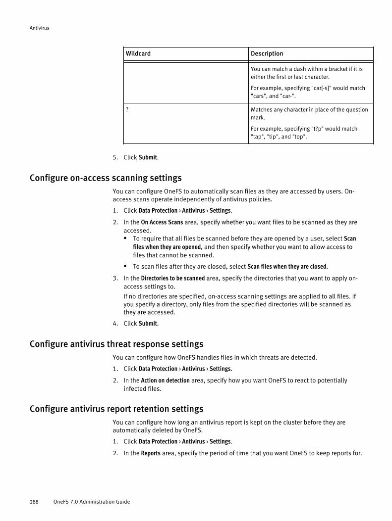
Wildcard Description- -
You can match a dash within a bracket if it iseither the first or last character.
For example, specifying "car[-s]" would match"cars", and "car-".
? Matches any character in place of the questionmark.
For example, specifying "t?p" would match"tap", "tip", and "top".
5. Click Submit.
Configure on-access scanning settingsYou can configure OneFS to automatically scan files as they are accessed by users. On-access scans operate independently of antivirus policies.
1. Click Data Protection > Antivirus > Settings.
2. In the On Access Scans area, specify whether you want files to be scanned as they areaccessed.l To require that all files be scanned before they are opened by a user, select Scan
files when they are opened, and then specify whether you want to allow access tofiles that cannot be scanned.
l To scan files after they are closed, select Scan files when they are closed.
3. In the Directories to be scanned area, specify the directories that you want to apply on-access settings to.
If no directories are specified, on-access scanning settings are applied to all files. Ifyou specify a directory, only files from the specified directories will be scanned asthey are accessed.
4. Click Submit.
Configure antivirus threat response settingsYou can configure how OneFS handles files in which threats are detected.
1. Click Data Protection > Antivirus > Settings.
2. In the Action on detection area, specify how you want OneFS to react to potentiallyinfected files.
Configure antivirus report retention settingsYou can configure how long an antivirus report is kept on the cluster before they areautomatically deleted by OneFS.
1. Click Data Protection > Antivirus > Settings.
2. In the Reports area, specify the period of time that you want OneFS to keep reports for.
Antivirus
288 OneFS 7.0 Administration Guide

Enable or disable antivirus scanningYou can enable or disable all antivirus scanning.
1. Click Data Protection > Antivirus > Summary.
2. In the Service area, enable or disable antivirus scanning.l Click Enable.
l Click Disable.
Managing ICAP serversBefore you can send files to be scanned on an ICAP server, you must configure OneFS toconnect to the server. You can test, modify, and remove an ICAP server connection. Youcan also temporarily disconnect and reconnect to an ICAP server.
Add and connect to an ICAP serverYou can add and connect to an ICAP server. After a server is added, OneFS can send filesto the server to be scanned for viruses.
1. Click Data Protection > Antivirus > Summary.
2. In the ICAP Servers area, click Add server.
3. In the Add ICAP Server dialog box, in the ICAP URL field, type the IP address of the ICAPserver you want to connect to.
4. In the Description field, type a description of this ICAP server.
5. Click Submit.The ICAP server is displayed in the ICAP Servers table.
Test an ICAP server connectionYou can test the connection between the cluster and an ICAP server.
1. Click Data Protection > Antivirus > Summary.
2. In the ICAP Servers table, in the row of the ICAP server whose connection you want totest, click Test connection.If the connection test succeeds, the Status column displays a green icon. If theconnection test fails, the Status column displays a red icon.
Modify ICAP connection settingsYou can modify the IP address and optional description of ICAP server connections.
1. Click Data Protection > Antivirus > Summary.
2. In the ICAP Servers table, in the row of the ICAP server whose connection settings youwant to modify, click Edit.
3. Modify settings as needed, and then click Submit.
Temporarily disconnect from an ICAP serverIf you want to prevent OneFS from sending files to an ICAP server, but want to retain theICAP server connection settings, you can temporarily disconnect from the ICAP server.
1. Click Data Protection > Antivirus > Summary.
Antivirus
Enable or disable antivirus scanning 289

2. In the ICAP Servers table, in the row of the ICAP server that you want to temporarilydisconnect from, click Disable.
Reconnect to an ICAP serverYou can reconnect to an ICAP server that you have temporarily disconnected from.
1. Click Data Protection > Antivirus > Summary.
2. In the ICAP Servers table, in the row of the ICAP server that you want to reconnect to,click Enable.
Remove an ICAP serverIf you are no longer using an ICAP server connection, you can permanently disconnectfrom the ICAP server.
1. Click Data Protection > Antivirus > Summary.
2. In the ICAP Servers table, in the row of the ICAP server that you want to remove, clickDelete.
Create an antivirus policyYou can create an antivirus policy that causes specific files to be scanned for viruseseach time the policy is run.
1. Click Data Protection > Antivirus > Policies.
2. Click Add policy.
3. In the Name field, type a name for this antivirus policy.
4. Click Add directory and select a directory that you want to scan.
Optionally, repeat this step to specify multiple directories.
5. In the Restrictions area, specify whether you want to enforce the file size and namerestrictions specified by the global antivirus settings.l Click Enforce file size and filename restrictions.
l Click Scan all files within the root directories.
6. In the Run policy area, specify whether you want to run the policy according to aschedule or manually.
Scheduled policies can also be run manually at any time.
Run the policy onlymanually.
Click Manually
Run the policy accordingto a schedule.
a. Click Scheduled.
b. In the Interval area, specify on what days you want thepolicy to run.
c. In the Frequency area, specify how often you want thepolicy to run on the specified days.
7. Click Submit.
Antivirus
290 OneFS 7.0 Administration Guide
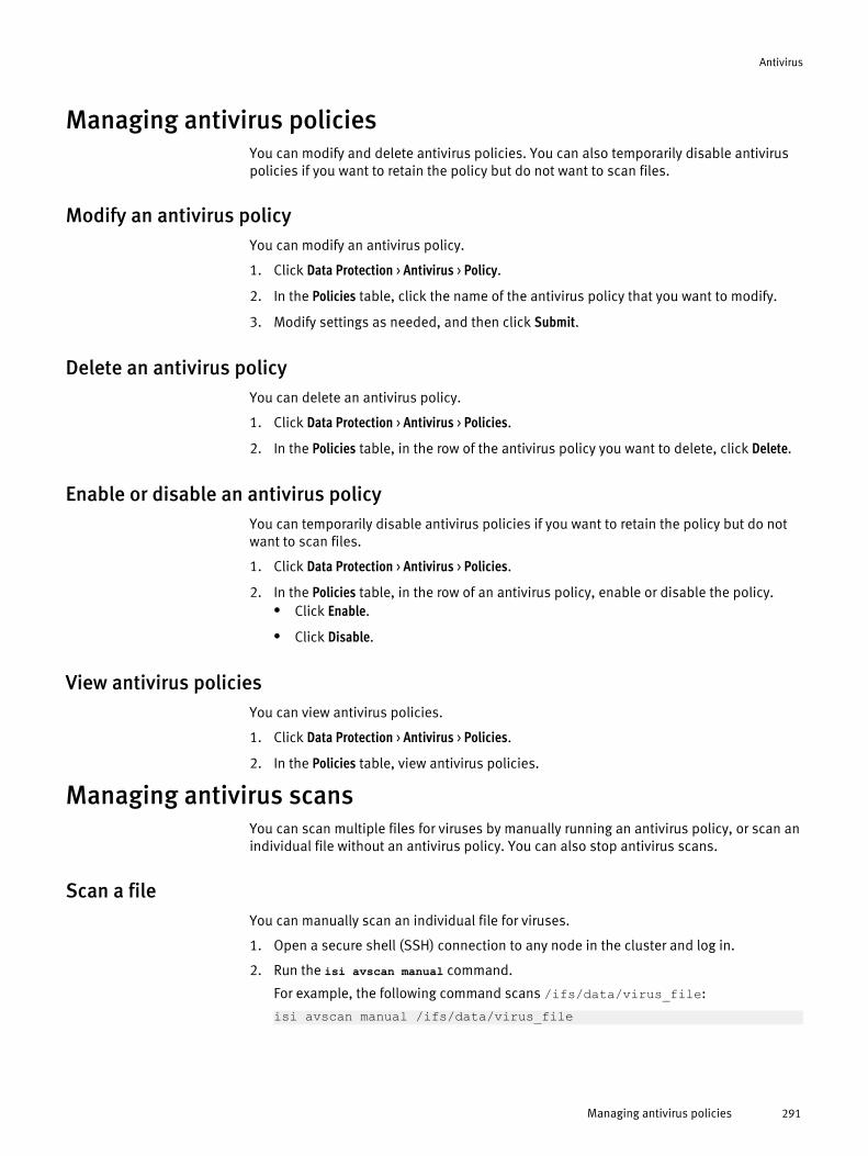
Managing antivirus policiesYou can modify and delete antivirus policies. You can also temporarily disable antiviruspolicies if you want to retain the policy but do not want to scan files.
Modify an antivirus policyYou can modify an antivirus policy.
1. Click Data Protection > Antivirus > Policy.
2. In the Policies table, click the name of the antivirus policy that you want to modify.
3. Modify settings as needed, and then click Submit.
Delete an antivirus policyYou can delete an antivirus policy.
1. Click Data Protection > Antivirus > Policies.
2. In the Policies table, in the row of the antivirus policy you want to delete, click Delete.
Enable or disable an antivirus policyYou can temporarily disable antivirus policies if you want to retain the policy but do notwant to scan files.
1. Click Data Protection > Antivirus > Policies.
2. In the Policies table, in the row of an antivirus policy, enable or disable the policy.l Click Enable.
l Click Disable.
View antivirus policiesYou can view antivirus policies.
1. Click Data Protection > Antivirus > Policies.
2. In the Policies table, view antivirus policies.
Managing antivirus scansYou can scan multiple files for viruses by manually running an antivirus policy, or scan anindividual file without an antivirus policy. You can also stop antivirus scans.
Scan a fileYou can manually scan an individual file for viruses.
1. Open a secure shell (SSH) connection to any node in the cluster and log in.
2. Run the isi avscan manual command.
For example, the following command scans /ifs/data/virus_file:
isi avscan manual /ifs/data/virus_file
Antivirus
Managing antivirus policies 291
Manually run an antivirus policyYou can manually run an antivirus policy at any time.
1. Click Data Protection > Antivirus > Policies .
2. In the Policies table, in the row of the policy you want to run, click Start.
Stop a running antivirus scanYou can stop a running antivirus scan.
1. Click Data Protection > Antivirus > Summary.
2. In the Currently Running table, in the row of the antivirus scan you want to stop, clickCancel.
Managing antivirus threatsYou can repair, quarantine, or truncate files in which threats are detected. If you believethat a quarantined file is no longer a threat, you can rescan the file or remove the file fromquarantine.
Manually quarantine a fileYou can quarantine a file to prevent the file from being accessed by users.
1. Click Data Protection > Antivirus > Detected Threats.
2. In the Detected Threats table, in the row of a file, click Quarantine.
Rescan a fileYou can rescan the file for viruses if, for example, you believe that a file is no longer athreat.
1. Click Data Protection > Antivirus > Detected Threats.
2. In the Detected Threats table, in the row of a file, click Rescan.
Remove a file from quarantineYou can remove a file from quarantine if, for example, you believe that the file is nolonger a threat.
1. Click Data Protection > Antivirus > Detected Threats.
2. In the Detected Threats table, in the row of a file, click Restore.
Manually truncate a fileIf a threat is detected in a file, and the file is irreparable and no longer needed, you cantruncate the file.
1. Click Data Protection > Antivirus > Detected Threats.
2. In the Detected Threats table, in the row of a file, click Truncate.The Confirm dialog box appears.
3. Click Yes.
Antivirus
292 OneFS 7.0 Administration Guide
View threatsYou can view files that are identified as threats by an ICAP server.
1. Click Data Protection > Antivirus > Detected Threats.
2. In the Detected Threats table, view potentially infected files.
Antivirus threat informationYou can view information about the antivirus threats that OneFS detects.
u Status — Displays an icon that indicates the status of the detected threat. The icon appearsin one of the following colors:
u Red — OneFS did not take any action on the file.
u Orange — The file was truncated.
u Yellow — The file was quarantined.
u Threat — Displays the name of the detected threat as it is recognized by the ICAP server.
u Filename — Displays the name of the file.
u Directory — Displays the directory in which the file is located.
u Remediation — Indicates how OneFS responded to the file when the threat was detected. IfOneFS did not quarantine or truncate the file, Infected appears.
u Detected — Displays the time that the file was detected.
u Policy — Displays the name of the antivirus policy that detected the threat. If the threat wasdetected as a result of a manual antivirus scan of an individual file, Manual scan appears.
u Currently — Displays the current state of the file.
u File size — Displays the size of the file, in bytes. Truncated files display a size of zero bytes.
Managing antivirus reportsIn addition to viewing antivirus reports through the web administration interface, you canexport reports to a comma-separated values (CSV) file. You can also view events that arerelated to antivirus activity.
Export an antivirus reportYou can export an antivirus report to a comma separated values (CSV) file.
1. Click Data Protection > Antivirus > Reports .
2. In the Reports table, in the row of a report, click Export.
3. Save the CSV file.
View antivirus reportsYou can view antivirus reports.
1. Click Data Protection > Antivirus > Reports.
2. In the Reports table, in the row of a report, click View Details.
Antivirus
View threats 293

View antivirus eventsYou can view events that relate to antivirus activity.
1. Click Dashboard > Events > Event History.
2. In the Event History table, view all events.
All events related to antivirus scans are classified as warnings. The following eventsare related to antivirus activities:
u Anti-Virus scan found threats — A threat was detected by an antivirus
scan. These events do not provide threat details, but refer to specific reports on theAntivirus Reports page.
u No ICAP Servers available — OneFS is unable to communicate with any
ICAP servers.
u ICAP Server Unresponsive or Invalid — OneFS is unable to
communicate with an ICAP server.
Antivirus
294 OneFS 7.0 Administration Guide
CHAPTER 16
iSCSI
As an alternative to file-based storage, block-based storage is a flexible way to store andaccess nearly any type of data. The Isilon iSCSI module enables you to provide blockstorage for Microsoft Windows, Linux, and VMware systems over an IP network.
The Isilon iSCSI module requires a separate license. To obtain additionalinformation about the iSCSI module or to activate the module for your cluster, contactyour EMC Isilon sales representative.
The Isilon iSCSI module enables you to create and manage iSCSI targets on an Isiloncluster. The targets become available as SCSI block devices on which clients can storestructured and unstructured data. iSCSI targets contain one or more logical units, eachuniquely identified by a logical unit number (LUN), which the client can format on thelocal file system and connect to (such as a physical disk device).
You can configure separate data protection levels for each logical unit with IsilonFlexProtect or data mirroring.
For basic access control, you can configure each target to limit access to a list ofinitiators. You can also require initiators to authenticate with a target by using theChallenge-Handshake Authentication Protocol (CHAP).
The iSCSI module includes the following features:
u Support for using a Microsoft Internet Storage Name Service (iSNS) server
u Isilon SmartConnect Advanced dynamic IP allocation
u Isilon FlexProtect
u Data mirroring from 2x to 8x
u LUN cloning
u One-way CHAP authentication
u Initiator access control
u iSCSI targets and LUNs........................................................................................296u iSNS client service...............................................................................................296u Access control for iSCSI targets...........................................................................297u iSCSI considerations and limitations...................................................................297u Supported SCSI mode pages...............................................................................298u Supported iSCSI initiators...................................................................................298u Configuring the iSCSI and iSNS services..............................................................298u Create an iSCSI target..........................................................................................299u Managing iSCSI targets.......................................................................................301u Configuring iSCSI initiator access control............................................................302u Creating iSCSI LUNs.............................................................................................305u Managing iSCSI LUNs..........................................................................................309
iSCSI 295

iSCSI targets and LUNsA logical unit defines a storage object (such as a disk or disk array) that is madeaccessible by an iSCSI target on an Isilon cluster. Each logical unit is uniquely identifiedby a logical unit number (LUN). Although a LUN is an identifier for a logical unit, the termsare often used interchangeably.
A logical unit must be associated with a target, and each target can contain one ormore logical units.
The following table describes the three types of LUNs that the Isilon iSCSI modulesupports:
LUN Type Description- -Normal This is the default LUN type for clone LUNs and
imported LUNs, and the only type available fornewly created LUNs. Normal LUNs can be eitherwriteable or read-only.
Snapshot A snapshot LUN is a copy of a normal LUN oranother snapshot LUN. Although snapshotLUNs require little time and disk space tocreate, they are read-only. You can createsnapshot LUNs by cloning existing normal orsnapshot LUNs, but you cannot create snapshotclones of clone LUNs.
Clone A clone LUN is a copy of a normal, snapshot, orclone LUN. A clone LUN, which is a compromisebetween a normal LUN and a snapshot LUN, isimplemented using overlay and mask files inconjunction with a snapshot. Clone LUNsrequire little time and disk space to create, andthe LUN is fully writeable. You can create cloneLUNs by cloning or importing existing LUNs.
Using SmartConnect with iSCSI targetsWhen connecting to iSCSI targets, the initiator can specify a SmartConnect service IP orvirtual IP address.
When an initiator connects to a target with the SmartConnect service, the iSCSI session isredirected to a node in the cluster, based on the SmartConnect connection policysettings. The default connection policy setting is round robin. If the SmartConnect serviceis configured to use dynamic IP allocation, which requires a SmartConnect Advancedlicense key, connections are redirected to other nodes in case of failure.
iSNS client serviceThe Internet Storage Name Service (iSNS) protocol is used by iSCSI initiators to discoverand configure iSCSI targets.
The iSCSI module supports the Microsoft iSNS server for target discovery. The iSNS serverestablishes a repository of active iSCSI nodes, which can then be used as initiators ortargets. Additionally, the iSNS client service can be enabled, disabled, configured, andtested through the iSCSI module in OneFS.
iSCSI
296 OneFS 7.0 Administration Guide
Access control for iSCSI targetsThe iSCSI module supports Challenge-Handshake Authentication Protocol (CHAP) andinitiator access control for connections to individual targets.
The CHAP and initiator access control security options can be implemented together orused separately.
CHAP authenticationThe iSCSI module supports the Challenge-Handshake Authentication Protocol (CHAP) toauthenticate initiator connections to iSCSI targets.
You can restrict initiator access to a target by enabling CHAP authentication and thenadding user:secret pairs to the target's CHAP secrets list. Enabling CHAP authenticationrequires initiators to provide a valid user:secret pair to authenticate their connections tothe target. CHAP authentication is disabled by default.
The Isilon iSCSI module does not support mutual CHAP authentication.
Initiator access controlYou can control which initiators are allowed to connect to a target by enabling initiatoraccess control and configuring the target's initiator access list. By default, initiator accesscontrol is disabled, and all initiators are allowed to access the target.
You can restrict access to a target by enabling access control and then adding initiatorsto the target's initiator access list. If you enable access control but leave the initiatoraccess list empty, no initiators are able to access the target.
iSCSI considerations and limitationsWhen planning your iSCSI deployment, be aware of the following limitations andconsiderations.
u Multipath I/O (MPIO) is recommended only for iSCSI workflows with primarily read-only operations, because the node must invalidate the data cache on all other nodesduring file-write operations and because performance decreases in proportion to thenumber of write operations. If all MPIO sessions are connected to the same node,performance should not decrease.
u The Isilon iSCSI module supports one-way Challenge-Handshake AuthenticationProtocol (CHAP), with the target authenticating the initiator. The authenticationconfiguration is shared by all of the nodes, so a target authenticates its initiatorregardless of the node the initiator is connecting through. Mutual CHAPauthentication between an initiator and a target is not supported.
u The Isilon iSCSI module supports the importing of normal LUNs only; importingsnapshot LUNs and clone LUNs is not supported. You cannot back up and thenrestore a snapshot or clone LUN, or replicate snapshot or clone LUNs to anothercluster. It is recommended that you deploy a backup application to back up iSCSILUNs on the iSCSI client, as the backup application ensures that the LUN is in aconsistent state at the time of backup.
u The Isilon iSCSI module does not support the following:l Internet Protocol Security (IPsec)
l Multiple connections per session (MCS)
l iSCSI host bus adaptors (HBAs)
iSCSI
Access control for iSCSI targets 297

Supported SCSI mode pagesThe SCSI Mode Sense command is used to obtain device information from mode pages ina target device. The Mode Select command is used to set new values.
OneFS supports the following mode pages:
Mode page name Page code Subpage code- - -Caching mode page* 08h 00h
Return all mode pages only 3Fh 00h
Control mode page** 0Ah 00h
Informational exceptionscontrol mode page
1Ch 00h
* For the caching mode page, OneFS supports the write cache enable (WCE) parameteronly.
** OneFS supports querying this mode page through the Mode Sense command, butdoes not support changing the fields of this page through the Mode Select command.
Supported iSCSI initiatorsOneFS 7.0.0 or later is compatible with the following iSCSI initiators.
Operating System iSCSI Initiator- -Microsoft Windows 2003 (32-bit and 64-bit) Microsoft iSCSI Initiator 2.08 or later (Certified)
Microsoft Windows 2008 (32-bit and 64-bit) Microsoft iSCSI Initiator (Certified)
Microsoft Windows 2008 R2 (64-bit only) Microsoft iSCSI Initiator (Certified)
Red Hat Enterprise Linux 5 Linux Open-iSCSI Initiator (Supported)
VMware ESX 4.0 and ESX 4.1 iSCSI Initiator (Certified)
VMware ESXi 4.0 and ESXi 4.1 iSCSI Initiator (Certified)
VMware ESXi 5.0 iSCSI Initiator (Certified)
Configuring the iSCSI and iSNS servicesYou can disable or enable and configure the iSCSI service and the iSNS client service. TheiSNS client service is used by iSCSI initiators to discover targets. These settings areapplied to all of the nodes in the cluster. You cannot modify these settings for individualnodes.
Configure the iSCSI serviceYou can enable or disable the iSCSI service for all the nodes in a cluster.
Before you disable the iSCSI service, be aware of the following considerations:
u All of the current iSCSI sessions will be terminated for all the nodes in the cluster.
u Initiators cannot establish new sessions until the iSCSI service is re-enabled.
iSCSI
298 OneFS 7.0 Administration Guide
1. Click File System Management > iSCSI > Settings.
2. In the iSCSI Service area, set the service state that you want:l If the service is disabled, you can enable it by clicking Enable.
l If the service is enabled, you can disable it by clicking Disable.
Configure the iSNS client serviceYou can configure and enable or disable the Internet Storage Name Service (iSNS), whichiSCSI initiators use to discover targets.
1. Click File System Management > iSCSI > Settings.
2. In the iSNS Client Service area, configure the iSNS client service settings:l iSNS server address: Type the IP address of the iSNS server with which you want to
register iSCSI target information.
l iSNS server port: Type the iSNS server port number. The default port number is3205.
3. Click Test connection to validate the iSNS configuration settings.If the connection to the iSNS server fails, check the iSNS server address and the iSNSserver port number.
4. Click Submit.
5. Change the service to the state that you want:l If the service is disabled, you can enable it by clicking Enable. Enabling the service
allows OneFS to register information about iSCSI targets.
l If the service is enabled, you can disable it by clicking Disable. Disabling theservice prevents OneFS from registering information about iSCSI targets.
View iSCSI sessions and throughputIf the iSCSI service is enabled on the cluster, you can view a summary of current iSCSIsessions and current throughput.
To view historic iSCSI throughput data, you must obtain the EMC Isilon InsightIQvirtual appliance, which requires a separate license. For more information, contact yourEMC Isilon representative.
1. Click File System Management > iSCSI > Summary.
2. Review the current throughput data and current session information.l The Current Throughput area displays a chart that illustrates overall inbound and
outbound throughput across all iSCSI sessions during the past hour, measured inkilobits per second (Kbps). This chart automatically updates every 15 seconds.
l The Current Sessions area displays information about each current connectionbetween an initiator and a target, including the client and target IP addresses;node, target, and LUN; operations per second; and the inbound, outbound, andtotal throughput in bits per second. You can view details about a target by clickingthe target name.
Create an iSCSI targetYou can configure one or more iSCSI targets, each with its own settings for initiatoraccess control and authentication. A target is required as a container object for one ormore logical units.
1. Click File System Management > iSCSI > Targets & Logical Units.
iSCSI
Configure the iSNS client service 299
2. In the Targets area, click Add target.
3. In the Name field, type a name for the target.
The name must begin with a letter and can contain only lowercase letters, numbers,and hyphens (-).
4. In the Description field, type a descriptive comment for the target.
5. In the Default path field, type the full path of the directory, beginning with /ifs, wherethe logical unit number (LUN) directory is created, or click Browse to select a directory.
This directory is used only if no other directory is specified during LUNcreation or if a LUN is not created. The directory must be in the /ifs directory tree.The full path to the directory is required, and wildcard characters are not supported.
6. Add one or more SmartConnect pools for the target to connect with. This settingoverrides any global default SmartConnect pools that are configured for iSCSI targets.
a. For the SmartConnect pool(s) setting, click Edit list.
b. Move pools between the Available Pools and Selected Pools lists by clicking a pooland then clicking the right or left arrow. To remove all selected pools at once, clickclear.
c. Click OK.
7. Click Submit.
8. Optional: In the Initiator Access Control area, enable and configure the settings forinitiator access control.a. Click Enable to restrict target access to initiators that are added to the initiator
access control settings.
b. Click Add initiator.
c. In the Initiator name field, type the name of the initiator that you want to allow toaccess this target, or click Browse to select from a list of initiators. An initiatorname must begin with an iqn. prefix.
d. Click OK.
To continue adding initiators, click OK and add another. When you are finishedadding initiators, click OK.
9. Optional: In the CHAP Authentication area, enable and configure Challenge-HandshakeAuthentication Protocol (CHAP) settings.
If CHAP authentication is enabled and the CHAP secrets list is empty, noinitiators can access the target.
a. Click Enable to require initiators to authenticate with the target.
b. Click Add username.
c. In the Username field, type the name that the initiator will use to authenticate withthe target. You can specify an initiator's iSCSI qualified name (IQN) as theusername. Depending on whether you specify an IQN, valid usernames differ inthe following ways:– If you specify an IQN as the username, the Username value must begin with an
iqn. prefix. The characters that are allowed after the iqn. prefix arealphanumeric characters, periods (.), hyphens (-), and colons (:).
– All other usernames can use alphanumeric characters, periods (.), hyphens (-),and underscores (_).
iSCSI
300 OneFS 7.0 Administration Guide
CHAP usernames and passwords are case-sensitive.
d. In the Secret and Confirm secret fields, type the secret that the initiator will use toauthenticate with the target. A CHAP secret must be 12 to 16 characters long andcan contain any combination of letters, numbers, and symbols.
e. Click OK.
10. Click Submit.
Managing iSCSI targetsYou can configure one or more targets for an iSCSI server, and each target can containone or more logical units.
The targets define connection endpoints and serve as container objects for logical unitson an iSCSI server. iSCSI initiators on clients establish connections to the targets.
You can control access to the target by configuring SmartConnect pools, initiator accesscontrol, and authentication with the Challenge-Handshake Authentication Protocol(CHAP). To discover targets, the iSCSI module works with a server running MicrosoftInternet Storage Name Service (iSNS).
Modify iSCSI target settingsYou can modify a target's description, change the path where logical unit directories arecreated, and modify the list of SmartConnect pools that the target uses. You can alsomanage the target's settings for initiator access control and authentication.
1. Click File System Management > iSCSI > Targets & Logical Units.
2. In the Targets area, under Actions, click Edit for the target that you want to modify.
3. Modify the target's settings as needed.
l Changing the default path does not affect existing logical units.
l Changing the security settings does not affect existing connections.
4. Click Submit.
Delete an iSCSI targetWhen you delete a target, all of the logical unit numbers (LUNs) that are contained in thetarget are also deleted, and all the data that is stored in the LUNs is deleted. Additionally,any iSCSI sessions that are connected to the target are terminated. This operation cannotbe undone.
1. Click File System Management > iSCSI > Targets & Logical Units.
2. In the Targets area, under Actions, click Delete for the target that you want to delete.
3. In the confirmation dialog box, click Yes.The target and all LUNs and LUN data that are contained in the target are deleted, andany iSCSI sessions on the target are terminated.
View iSCSI target settingsYou can view information about a target, including its iSCSI qualified name (IQN), defaultLUN directory path, capacity, and SmartConnect pool settings. You can also view the
iSCSI
Managing iSCSI targets 301

logical units that are associated with the target as well as the settings for initiator accesscontrol and authentication.
1. Click File System Management > iSCSI > Targets & Logical Units.
2. In the Targets area, click the name of a target.
3. Review the following sections for information on the target. To modify these settings,click Edit target.l Target Details: Displays the target name, IQN, description, default path, capacity,
and SmartConnect pool settings. The name and IQN cannot be modified.
l Logical Units: Displays any logical units that are contained in the target. You canadd or import a logical unit, or manage existing logical units. You can also selectthe columns to display or hide.
l Allowed Initiators: Displays the target's initiator access control status, and lists thenames of any initiators that are allowed to access the target when access controlis enabled.
l CHAP Authentication: Displays the target's CHAP authentication status, and lists alluser:secret pairs for the target.
Configuring iSCSI initiator access controlYou can configure access control to specify which initiators are allowed to connect to atarget.
If initiator access control is enabled for an iSCSI target, access to that target is limited toa specified list of allowed initiators. Access control is disabled by default.
Modifications to a target's access control settings are applied to subsequentconnection requests. Current connections are not affected.
Configure iSCSI initiator access controlYou can configure access control to specify which initiators are allowed to connect to atarget.
If initiator access control is enabled for an iSCSI target, access is limited to a list ofinitiators. Access control is disabled by default.
Modifications to a target's access control settings are applied to subsequentconnection requests. Current connections are not affected.
1. Click File System Management > iSCSI > Targets & Logical Units.
2. In the Targets area, under Actions, click Edit for the target whose initiator access stateyou want to change.
3. In the Initiator Access Control area, configure the access control state.l If access control is disabled, click Enable to restrict target access to initiators that
you add to the initiator access list.
If you disable access control and the initiator access list is empty, noinitiators are able to connect to the target.
l If access control is enabled, click Disable to allow all initiators access to the target.
If you disable access control, the list of allowed initiators is ignored.
iSCSI
302 OneFS 7.0 Administration Guide
4. Add initiators by clicking Add initiator.
Control initiator access to a targetYou can control access to a target by adding initiators to its initiator access list. If youenable initiator access control, the initiator access list specifies which initiator names areallowed to access the target. However, the initiator access list is ignored unless initiatoraccess control is enabled.
1. Click File System Management > iSCSI > Targets & Logical Units.
2. In the Targets area, under Actions, click Edit for the target that you want to allow aninitiator to access.
3. In the Initiator Access Control area, click Add initiator.
4. In the Initiator name field, type the name of the initiator that you want to allow toaccess the target, or click Browse to select from a list of known initiators. An initiatorname requires the iqn. prefix.
5. Click OK.
6. To continue adding initiators, click OK and add another.
7. When you are finished adding initiators, click OK.
Modify initiator nameYou can rename or replace an initiator that is allowed to connect to a target when accesscontrol is enabled.
1. Click File System Management > iSCSI > Targets & Logical Units.
2. In the Targets area, under Actions, click Edit for the target that you want to modify.
3. In the Initiator Access Control area, click Edit for the initiator that you want to modify.
4. Modify the initiator name.
5. Click OK.
Remove an initiator from the access listYou can remove an initiator from a target's initiator access list so that the initiator is nolonger able to connect to a target when access control is enabled.
u If you remove all of the allowed initiators for a target and access control is enabled,the target will deny new connections until you disable access control.
u Removing an allowed initiator for a target does not affect the initiator's access toother targets.
1. Click File System Management > iSCSI > Targets & Logical Units.
2. In the Targets area, under Actions, click Edit for the target that you want to modify.
3. In the Initiator Access Control area, under Actions, click Delete for the initiator that youwant to remove from the access list.
4. In the confirmation dialog box, click Yes.
iSCSI
Control initiator access to a target 303
Create a CHAP secretTo use CHAP authentication, you must create user:secret pairs in the target's CHAPsecrets list and enable CHAP authentication. Initiators must then authenticate with thetarget by providing a user:secret pair.
1. Click File System Management > iSCSI > Targets & Logical Units.
2. In the Targets area, under Actions, click Edit for the target that you want to create aCHAP secret for.
3. In the CHAP Authentication area, click Add username.
4. In the Username field, type the name that the initiator uses to authenticate with thetarget.
You can specify an initiator's iSCSI qualified name (IQN) as the username.
l If you specify an IQN as the username, the Username value must begin with an iqn.prefix. The characters that are allowed after the iqn. prefix are alphanumericcharacters, periods (.), hyphens (-), and colons (:).
l All other usernames can use alphanumeric characters, periods (.), hyphens (-),and underscores (_).
CHAP usernames and passwords are case-sensitive.
5. In the Secret and Confirm secret fields, type the secret that the initiator will use toauthenticate with the target. A CHAP secret must be 12 to 16 characters long and cancontain any combination of letters, numbers, and symbols.
6. Click OK.
Modify a CHAP secretYou can modify the settings for a CHAP user:secret pair.
1. Click File System Management > iSCSI > Targets & Logical Units.
2. In the Targets area, under Actions, click Edit for the target that you want to modify aCHAP user:secret pair for.
3. In the CHAP Authentication area, under Actions, click Edit for the username whosesettings you want to modify.
4. Make the changes that you want, and then click OK.
Delete a CHAP secretYou can delete a CHAP user:secret pair that is no longer needed.
If you delete all of a target's CHAP secrets and CHAP authentication is enabled, noinitiators are able to access the target until you disable CHAP authentication.
1. Click File System Management > iSCSI > Targets & Logical Units.
2. In the Targets area, under Actions, click Edit for the target that you want to delete aCHAP user:secret pair for.
3. In the CHAP Authentication area, under Actions, click Delete for the CHAP user:secret pairthat you want to delete.
iSCSI
304 OneFS 7.0 Administration Guide

4. In the confirmation dialog box, click Yes.
Enable or disable CHAP authenticationYou can enable or disable CHAP authentication for a target.
Modifications to a target's CHAP authentication status are applied to subsequentconnection requests. Current connections are unaffected.
1. Click File System Management > iSCSI > Targets & Logical Units.
2. In the Targets area, under Actions, click Edit for the target whose CHAP authenticationstate you want to modify.
3. In the CHAP Authentication area, configure the initiator's CHAP authentication state.l If CHAP authentication is disabled, you can click Enable to require initiators to
authenticate with the target.
If CHAP authentication is enabled and the CHAP secrets list is empty, noinitiator is able to access the target.
l If CHAP authentication is enabled, click Disable to stop authenticating initiatorswith the target.
If CHAP authentication is disabled, the CHAP secrets list is ignored.
4. Add CHAP user:secret pairs by clicking Add username.
Creating iSCSI LUNsThere are two methods by which you can add a LUN: you can create a new LUN, or youcan clone an existing LUN to form a new LUN.
When you create a LUN, you can set its target assignment, LUN number, directory path,size, provisioning policy, access state, write access, protection settings, and I/Ooptimization settings. The LUN number uniquely identifies the logical unit.
To clone a LUN, you must enable the Isilon SnapshotIQ module. SnapshotIQ is aseparately licensed feature. For more information, contact your EMC Isilon salesrepresentative.
Cloned copies of logical units can be part of the same target or a different target. LUNcloning, like LUN creation, is asynchronous. The status of in-progress cloning ismonitored in the same way as LUN creation. A cloned LUN is inaccessible by iSCSIinitiators until the cloning is complete.
Create an iSCSI LUNYou can create a logical unit and assign it to an iSCSI target for access.
When you create a logical unit, you must assign it to an existing iSCSI target. Eachtarget can contain one or more logical units.
1. Click File System Management > iSCSI > Targets & Logical Units.
2. In the Logical Units area, click Add logical unit.
3. In the Add Logical Unit area, in theDescription field, type a descriptive comment for thelogical unit.
iSCSI
Enable or disable CHAP authentication 305

4. From the Target list, select the target that will contain the logical unit.
5. Select one of the LUN number options.l To assign the next available number to the logical unit, click Automatic. This is the
default setting.
l To manually assign a number to the logical unit, click Manual and then, in theNumber field, type an integer value. The value must be within the range 0-255 andmust not be assigned to another logical unit within the target.
By default, the LUN number forms part of the directory name that is created forstoring the LUN data.
6. To manually specify the path where the LUN directory is created, in the Path field, typethe full path of the directory, beginning with /ifs, or click Browse to select thedirectory.
The directory must be in the /ifs directory tree. You must specify the full path to thedirectory, and wildcard characters are not allowed. The default path is /ifs/iscsi/ISCSI.LUN.<TargetName>.<LUNnumber>, where <TargetName> is the Target valueand <LUNnumber> is the LUN number.
7. In the Size field, specify the LUN capacity by typing an integer value and thenselecting a unit of measure from the list (MB, GB, or TB).
The minimum LUN size is 1 MB. The maximum LUN size is determined by the OneFSfile system. After you create a LUN, you can increase its size, but you cannot decreaseit.
8. Select one of the Provisioning options.l To specify that blocks are unallocated until they are written, click Thin provision.
l To immediately allocate all the blocks, click Pre-allocate space. This is the defaultsetting.
Allocation of all the blocks for a large LUN can take hours or even days.
9. Select one of the LUN access options.l To make the LUN accessible, click Online. This is the default setting.
l To make the LUN inaccessible, click Offline.
10. Select one of the Write access options.l To allow iSCSI initiators to write to the LUN, click Read-Write. This is the default
setting.
l To prevent iSCSI initiators from writing to the LUN, click Read-Only.
11. Under Protection Settings, from the Disk pool list, select the disk pool to contain thelogical unit.
12. From the SSD strategy list, select to specify a strategy to use if solid-state drives(SSDs) are available.l Metadata read acceleration (Recommended): Writes metadata and all user data on
hard disk drives (HDDs) and additionally creates a mirror backup of the data on anSSD. Depending on the global namespace acceleration setting, the SSD mirrormay be an extra mirror in addition to the number required to satisfy the protectionlevel.
l Metadata read/write acceleration with performance redundancy (Requires more SSDspace): Writes all metadata on an SSD and writes all user data on HDDs.
l Data on SSDs (Requires most SSD space): Similar to metadata acceleration, but alsowrites one copy of the file's user data (if mirrored) or all of the data (if notmirrored) on SSDs. Regardless of whether global namespace acceleration is
iSCSI
306 OneFS 7.0 Administration Guide

enabled, any SSD blocks reside on the file's target pool if there is room. This SSDstrategy does not create additional mirrors beyond the normal protection level.
l Avoid SSDs (Reduces performance): Never uses SSDs; writes all associate file dataand metadata to HDDs only.
13. From the Protection level list, select a protection policy for the logical unit. Select UseiSCSI default (2x), which is the recommended setting for best performance, or one ofthe mirrored options, such as 2x to 8x.
14. Select one of the Write Cache options.l To prevent write caching for files that contain LUN data, click Disabled. This is the
recommended setting for LUNs.
l To allow write caching for files that store LUN data, click Enable.
The Write Cache option controls whether file writes are sent to the coalescer orthe endurant cache. With Write Cache disabled, which is the default andrecommended setting, all file writes are sent to the endurant cache. The endurantcache is a committed data guarantee. If Write Cache is enabled, all file writes are sentto the coalescer. Write caching can improve performance, but can lead to data loss ifa node loses power or crashes while uncommitted data is in the write cache.
15. Select one of the Data access pattern options.l To select a random access pattern, click Random. This is the recommended setting
for LUNs.
l To select a concurrent access pattern, click Concurrency.
l To select a streaming access pattern, click Streaming. Streaming access patternscan improve performance in some workflows.
16. Click Submit.
Clone an iSCSI LUNYou can clone an existing LUN to a create a new LUN.
1. Click File System Management > iSCSI > Targets & Logical Units.
2. In the Logical Units area, under Actions, click Clone for the logical unit that you want toclone.The page updates and the clone options appear. Most of the fields for these optionsare populated with information from the logical unit you selected to clone.
3. From the LUN type list, select Normal, Clone, or Snapshot.
4. Modify the other settings as needed.
The settings for the clone vary according to the source LUN type.
5. Click Submit.
iSCSI LUN cloning operationsDepending on the clone LUN type, the contents (or blocks) of a source LUN are eithercopied or referenced, and the attributes may or may not be copied. In general, clone andsnapshot type clone operations are fast, whereas normal type clones can take severalminutes or even hours to create, depending on the size of the LUN.
The following table describes the result of each cloning operation.
iSCSI
Clone an iSCSI LUN 307

Source LUN type Clone LUN type Result- - -Normal Normal A snapshot of the source LUN is created.
The clone LUN is then created by copyingthe LUN data from the snapshot. Aftercompleting the copy, the snapshot isdeleted. The copy process may takeseveral hours to complete for large LUNs ifthe source LUN has a pre-allocatedprovisioning policy. The copy process mayalso take several minutes for thinlyprovisioned LUNs that are significantlyused.
Normal Snapshot A snapshot of the source LUN is created.The clone LUN is configured to referencethe data from the snapshot. The snapshotis deleted when the clone is deleted.
Normal Clone A snapshot of the source LUN is created.The system then creates a clone LUN thatreferences data from the snapshot.
Snapshot Normal The clone LUN is created by copying theLUN data from the snapshot. The copyprocess may take several minutes tocomplete for large LUNs if the source LUNhas a pre-allocated provisioning policy.The copy process may also take severalminutes for thinly provisioned LUNs thatare heavily used.
Snapshot Snapshot The clone LUN is configured to referencethe data from the same snapshot that thesource LUN references. The underlyingsnapshot is not deleted when a LUN isdeleted unless the LUN being deleted isthe last LUN referencing the snapshot.
Snapshot Clone The clone LUN is configured to referencethe data from the same snapshot that thesource LUN references. The underlyingsnapshot is not deleted when a LUN isdeleted unless the LUN being deleted isthe only LUN referencing the snapshot.
Clone Normal A snapshot of the source LUN is created.The clone LUN is then created by copyingthe LUN data from the snapshot. Aftercompleting the copy, the snapshot isdeleted. The copy process may takeseveral minutes to complete for largeLUNs if the source LUN has a pre-allocatedprovisioning policy. The copy process mayalso take several minutes for thinlyprovisioned LUNs that are heavily used
iSCSI
308 OneFS 7.0 Administration Guide

Source LUN type Clone LUN type Result- - -Clone Snapshot Not allowed.
Clone Clone A clone of the clone LUN is created. Theclone LUN is configured to reference datafrom the snapshot.
Managing iSCSI LUNsYou can manage a LUN by modifying it, migrating it to another target, viewing its settings,or deleting it. In addition, you can import a LUN that you replicated on a remote cluster.
After you create a LUN, you can manage it in the following ways:
u Modify a LUN
u Delete a LUN
u Migrate a LUN to another target
u Import a LUN
u View LUN settings
Modify an iSCSI LUNYou can modify only certain settings for a logical unit.
1. Click File System Management > iSCSI > Targets & Logical Units.
2. In the Logical Units area, under Actions, click Edit for the logical unit that you want tomodify.
3. Modify the logical unit's settings.
4. Click Submit.
Delete an iSCSI LUNDeleting a logical unit permanently deletes all data on the logical unit. This operationcannot be undone.
1. Click File System Management > iSCSI > Targets & Logical Units.
2. In the Logical Units area, under Actions, click Delete for the logical unit that you want todelete.
3. In the confirmation dialog box, click Yes.
Migrate an iSCSI LUN to another targetYou can move a logical unit from one target to another, change the value of its logical unitnumber (LUN), or update the path to the LUN directory. You cannot modify the path of asnapshot LUN.
The name of a logical unit comprises its target name and its LUN value. The two parts ofthe name are separated by a colon (such as "mytarget:0").
1. Click File System Management > iSCSI > Targets & Logical Units.
2. In the Logical Units area, under Actions, click Move for the logical unit that you want tomove.
3. In the To target list, click to select a new target for the logical unit.
iSCSI
Managing iSCSI LUNs 309
4. Click one of the To LUN number options.l To assign the next available number to the logical unit, click Automatic. This is the
default setting.
l To manually assign a number to the logical unit, click Manual and then, in theNumber box, type an integer value. The value must be within the range 0-255 andmust not be assigned to another logical unit.
5. To configure the path where the LUN directory is created, in the To path box, type thefull path of the directory, or click Browse to select the directory. If a path is notspecified, the LUN directory is unchanged from the original directory where that LUNwas created.
6. Click Submit.
Import an iSCSI LUNYou can recreate logical units that were replicated to a remote cluster or that were backedup and then restored to a remote cluster.
The iSCSI module does not support replicating or restoring logical unit snapshots or clonecopies.
1. Click File System Management > iSCSI > Targets & Logical Units.
2. In the Logical Units area, click Import logical unit.
3. In the Description field, type a descriptive comment for the logical unit.
4. In the Source path field, type the full path (beginning with /ifs) of the directory thatcontains the logical unit that you want to import, or click Browse to select thedirectory.
5. From the Target list, select the target that will contain the logical unit.
6. Select one of the LUN number options.l To assign the next available number to the logical unit, click Automatic. This is the
default setting.
l To manually assign a number to the logical unit, click Manual, and then in theNumber field, type an integer value. The value must be within the range 0-255 andmust not be assigned to another logical unit.
7. Select one of the LUN access options.l To make the LUN accessible, click Online. This is the default setting.
l To make the LUN inaccessible, click Offline.
8. Select one of the Write access options.l To allow iSCSI initiators to write to the LUN, click Read-Write. This is the default
setting.
l To prevent iSCSI initiators from writing to the LUN, click Read-Only.
9. Select one of the caching options.l To allow write caching for files storing LUN data, click Enabled.
l To prevent write caching for files storing LUN data, click Disabled.
10. Click Submit.
iSCSI
310 OneFS 7.0 Administration Guide

View iSCSI LUN settingsYou can view information about a logical unit, including its logical unit number (LUN),iSCSI target, LUN type, LUN directory path, iSCSI qualified name, and other settings.
1. Click File System Management > iSCSI > Targets & Logical Units.
2. In the Logical Units area, under Target:LUN, click the name of the logical unit that youwant to view.
3. The following settings display:l LUN: Displays the numerical identifier of the logical unit. You can modify the LUN
value by using the move operation.
l Target: Displays the name of the iSCSI target that contains the logical unit. Youcan modify the target by using the move operation.
l Description: Displays an optional description for the logical unit. You can modifythe description by clicking Edit LUN.
l Type: Displays the LUN type (normal, clone, or snapshot). You cannot modify thissetting.
l Size: Displays the LUN capacity. You can increase the size of normal or snapshotLUNs by clicking Edit LUN, but you cannot decrease the size. You cannot modifythe size of snapshot LUNs.
l Status: Displays the connection status (online or offline) and write accesspermissions (read-only or read-write) of the LUN. You can modify write-accesssettings for normal or clone LUNs by clicking Edit LUN. You cannot modify write-access settings for snapshot LUNs.
l Path: Displays the path to the directory where the LUN files are stored. You canchange the path for normal or snapshot LUNs by using the move operation. Youcannot modify the path for snapshot LUNs.
l Disk pool: Displays the disk pool of the LUN. You can modify the disk pool byclicking Edit LUN.
l Protection level: Displays the mirroring level (such as 2x, 3x, 4x, and so on) orFlexProtect protection policy for the LUN. You can modify the protection policy fornormal or clone LUNs by clicking Edit LUN. You cannot modify these settings forsnapshot LUNs.
l Write Cache: Displays whether SmartCache is enabled or disabled. You canchange this setting for normal or clone LUNs by clicking Edit LUN. You cannotmodify these settings for snapshot LUNs.
l Data access pattern: Displays the access pattern setting (Random, Concurrency,or Streaming) for the LUN. You can change the access pattern for normal or cloneLUNs by clicking Edit LUN. You cannot modify these settings for snapshot LUNs.
l SCSI name: Displays the iSCSI qualified name (IQN) of the LUN. You cannot modifythis setting.
l EUI: Displays the extended unique identifier (EUI), which uniquely identifies theLUN. You cannot modify this setting.
l NAA: Displays the LUN's T11 Network Address Authority (NAA) namespace. Youcannot modify this setting.
l Serial number: Displays the serial number of the LUN. You cannot modify thissetting.
iSCSI
View iSCSI LUN settings 311

iSCSI
312 OneFS 7.0 Administration Guide

CHAPTER 17
VMware integration
OneFS integrates with VMware infrastructures, including vSphere, vCenter, and ESXi.VMware integration enables you to view information about and interact with Isilonclusters through VMware applications.
OneFS interacts with VMware infrastructures through VMware vSphere API for StorageAwareness (VASA) and VMware vSphere API for Array Integration (VAAI).
OneFS integrates with VMware vCenter through the Isilon for vCenter plug-in. The Isilonfor vCenter plug-in enables you to locally backup and restore virtual machines on anIsilon cluster. For more information about Isilon for vCenter, see the following documents:
u Isilon for vCenter Release Notes
u Isilon for vCenter Installation Guide
u Isilon for vCenter User Guide
u VASA...................................................................................................................314u VAAI....................................................................................................................315u Configuring VASA support...................................................................................315u Disable or re-enable VASA...................................................................................316
VMware integration 313
VASAOneFS communicates with VMware vSphere through VMware vSphere API for StorageAwareness (VASA).
VASA support enables you to view information about Isilon clusters through vSphere,including Isilon-specific alarms in vCenter. VASA support also enables you to integratewith VMware profile driven storage by providing storage capabilities for Isilon clusters invCenter. For OneFS to communicate with vSphere through VASA, your VMwareenvironment must include ESXi 5.0 or later hypervisors.
To configure VASA support, you must access the cluster through the root account.Because SmartLock compliance mode disables root access to the cluster, the clustermust not be running in compliance mode.
Isilon VASA alarmsIf the VASA service is enabled on an Isilon cluster and the cluster is added as a VMwarevSphere API for Storage Awareness (VASA) vendor provider in vCenter, OneFS isgenerates alarms in vSphere.
The following table describes the alarm that OneFS generates:
Alarm name Description- -Thin-provisioned LUN capacity exceeded There is not enough available space on the
cluster to allocate space for writing data tothinly provisioned LUNs. If this conditionpersists, you will not be able to write to thevirtual machine on this cluster. To resolve thisissue, you must free storage space on thecluster.
VASA storage capabilitiesOneFS integrates with VMware vCenter through VMware vSphere API for StorageAwareness (VASA) to display storage capabilities of Isilon clusters in vCenter.
The following storage capabilities are displayed through vCenter:
u Archive — The Isilon cluster is composed of Isilon NL-Series nodes. The cluster is configuredfor maximum capacity.
u Performance — The Isilon cluster is composed of Isilon i-Series, Isilon X-Series, or Isilon S-Series nodes. The cluster is configured for maximum performance.
The Isilon I-Series and X-Series nodes contain Solid State Drives (SSDs). If acluster is composed of i-Series, X-Series , or S-Series nodes, but does not containSSDs, the cluster is recognized as a capacity cluster.
u Capacity — The Isilon cluster is composed of Isilon X-Series nodes that do not contain SSDs.The cluster is configured for a balance between performance and capacity.
u Hybrid — The Isilon cluster is composed of nodes associated with two or more storagecapabilities. For example, if the cluster contained both Isilon S-Series and NL-Series nodes, thestorage capability of the cluster is displayed as Hybrid.
VMware integration
314 OneFS 7.0 Administration Guide

VAAIOneFS uses VMware vSphere API for Array Integration (VAAI) to support offloadingspecific virtual machine storage and management operations from VMware ESXihypervisors to an Isilon cluster.
VAAI support enables you to accelerate the process of creating virtual machines andvirtual disks. For OneFS to interact with your vSphere environment through VAAI, yourVMware environment must include ESXi 5.0 or later hypervisors.
If you enable VAAI capabilities for an Isilon cluster, when you clone a virtual machineresiding on the cluster through VMware, OneFS clones the files related to that virtualmachine. For more information on file clones, see Clones.
VAAI support for block storageOneFS support for VMware vSphere API for Array Integration (VAAI) for block storage isenabled by default.
OneFS supports the following VAAI primitives for block storage:
u Hardware Assisted Lockingu Full Copyu Block Zeroing
OneFS does not support the thin provisioning block reclaim mechanism.
VAAI support for NASTo enable OneFS to use VMware vSphere API for Array Integration (VAAI) for NAS, youmust install the VAAI NAS plug-in for Isilon on the ESXi server.
For more information on the VAAI NAS plug-in for Isilon, see the VAAI NAS plug-in forIsilon Release Notes.
Configuring VASA supportTo enable VMware vSphere API for Storage Awareness (VASA) support for a cluster, youmust enable the VASA daemon on the cluster, download the Isilon vendor providercertificate and add the Isilon vendor provider in vCenter.
Enable VASAYou must enable an Isilon cluster to communicate with VMware vSphere API for StorageAwareness (VASA) by enabling the VASA daemon.
1. Open a secure shell (SSH) connection to any node in the cluster and log in.
2. Enable VASA by running the following command:isi services isi_vasa_d enable
Download the Isilon vendor provider certificateTo add an Isilon cluster VASA vendor provider in VMware vCenter, you must use a vendorprovider certificate. You can download a vendor provider certificate from an Isilon cluster.
1. In a supported web browser, connect to an Isilon cluster at //<IPAddress>, where<IPAddress> is the IP address of the Isilon cluster.
2. Retrieve the security certificate and save the certificate to a location on your machine.
VMware integration
VAAI 315

For more information about exporting a security certificate, see the documentation ofyour browser.
Record the location of where you saved the certificate. You will need this filepath when adding the vendor provider in vCenter.
Add the Isilon vendor providerYou must add an Isilon cluster as a vendor provider in VMware vCenter before you canview information about the storage capabilities of the cluster through vCenter.
Before you beginDownload a vendor provider certificate.
1. In vCenter, navigate to the Add Vendor Provider window.
2. Fill out the following fields in the Add Vendor Provider window:
u Name — Type a name for this VASA provider. Specify as any string. For example, typeEMC Isilon Systems.
u URL — Type http://<IPAddress>:8081/vasaprovider, where <IPAddress>
is the IP address of a node in the Isilon cluster.
u Login — Type root.
u Password — Type the password of the root user.
u Certificate location — Type the file path of the vendor provider certificate for thiscluster.
3. Select the Use Vendor Provider Certificate box.
4. Click OK.
Disable or re-enable VASAYou can disable or re-enable an Isilon cluster to communicate with VMware vSpherethrough VMware vSphere API for Storage Awareness (VASA).
To disable support for VASA, you must disable both the VASA daemon and the Isilon webadministration interface. You will not be able to administer the cluster through aninternet browser while the web interface is disabled. To re-enable support for VASA, youmust enable both the VASA daemon and the web interface.
1. Open a secure shell (SSH) connection to any node in the cluster and log in.
2. Disable or enable the web interface by running one of the following commands:l isi services apache2 disablel isi services apache2 enable
3. Disable or enable the VASA daemon by running one of the following commands:l isi services isi_vasa_d disablel isi services isi_vasa_d enable
VMware integration
316 OneFS 7.0 Administration Guide

CHAPTER 18
File System Explorer
The File System Explorer is a web-based interface that enables you to manage the contentstored on the cluster. You can use the File System Explorer to navigate the Isilon filesystem (/ifs), add directories, and manage file and directory properties including dataprotection, I/O optimization, and UNIX permissions.
Isilon file system directory permissions are initially set to allow full access for all users.Any user can delete any file, regardless of the permissions on the individual file.Depending on your environment, you want to establish permission restrictions throughthe File System Explorer.
You can view and configure file and directory properties from within Windows clients thatare connected to the cluster. However, because Windows and UNIX permissions differfrom one another, you must be careful not to make any unwanted changes that affect fileand directory access.
The File System Explorer displays up to 1000 files in a directory. If more than1000 files exist within a directory, the files are displayed without additional information,such as file size and last modified date.
u Browse the file system........................................................................................318u Create a directory................................................................................................318u Modify file and directory properties.....................................................................318u View file and directory properties........................................................................318u File and directory properties................................................................................319
File System Explorer 317
Browse the file systemYou can browse the Isilon file system (/ifs) through the File System Explorer.
1. Navigate to File System Management > File System Explorer.
2. View files and directories.l You can expand and collapse directories in the Directories pane.
l The contents of the selected directory are displayed in the right pane. You canview the contents of another directory by clicking the directory in the Directoriespane.
Create a directoryYou can create a directory under /ifs through the File System Explorer.
1. Navigate to File System Management > File System Explorer.
2. In the Directories pane, specify where you want to create the directory.
3. Click Add Directory.
4. In the New Directory Properties dialog box, in the Directory name field, type a name forthe directory.
5. From the User list, select the owner of the directory.
6. From the Group list, select the group for the directory.
7. From the Permissions table, specify the basic permissions for the directory.
8. Click Submit.
Modify file and directory propertiesYou can modify the data protection, I/O optimization, and UNIX permission properties offiles and directories through the File System Explorer.
1. Navigate to File System Management > File System Explorer.
2. In the Directories pane, click the directory that contains the file or directory that youwant to modify permissions for.
3. In the right pane, in the row of the file or directory you want to modify permissions for,click Properties.
4. In the Properties dialog box, specify the properties of the file or directory.
5. Click Submit.
View file and directory propertiesYou can view the data protection, I/O optimization, and UNIX permission properties offiles and directories through the File System Explorer.
1. Navigate to File System Management > File System Explorer.
2. In the Directories pane, click the directory that contains the file or directory that youwant to view permissions for.
3. In the right pane, in the row of the file or directory you want to view permissions for,click Properties.
4. In the Properties dialog box, view the properties of the file or directory.
File System Explorer
318 OneFS 7.0 Administration Guide

File and directory propertiesEach file and directory is assigned specific data protection, I/O optimization, and UNIXpermission properties that you can view through the File System Explorer.
The following properties are displayed in the Properties dialog box of the File SystemExplorer:
Protection Settings
u Settings management — Specifies whether protection settings are managed manually orby SmartPools. If you modify either or both protection settings, this property automaticallyrefreshes to Manually managed. If you specify Managed by SmartPools, the protection
settings will automatically refresh to match the SmartPools specifications the next time theSmartPools job is run.
u Disk pool — The disk pool whose protection policy is applied if SmartPools is configured tomanage protection settings. This property is available only if SmartPools is licensed andenabled on the cluster.
u SSD — The SSD strategy that will be used for user data and metadata if solid-state drives(SSDs) are available. The following SSD strategies are available:
u Metadata acceleration — OneFS creates a mirror backup of file metadata on an SSDand writes the rest of the metadata plus all user data to hard disk drives (HDDs).Depending on the global namespace acceleration setting, the SSD mirror might be an extramirror in addition to the number required to satisfy the protection level.
u Avoid SSDs — OneFS does not write data or metadata to SSDs. OneFS writes all dataand metadata to HDDs only.
u Data on SSDs — Similar to metadata acceleration, OneFS creates a mirror backup offile metadata on an SSD and writes the rest of the metadata plus all user data to hard diskdrives. However, OneFS also writes one copy of the file user data (if mirrored) or all of thedata (if not mirrored) to SSDs. All SSD blocks reside on the file target pool if there isadequate space available, regardless of whether global namespace acceleration isenabled. OneFS does not create additional mirrors beyond the normal protection level.
u Protection level — The FlexProtect or data mirroring protection policy for this file ordirectory. If SmartPools is licensed and enabled on the cluster, the default protection policy forfiles and directories is inherited from the specified disk pool.
I/O Optimization Settings
u Settings Management — Specifies whether I/O Optimization Settings are managedmanually or by SmartPools. If you modify either or both I/O optimization settings, this propertyautomatically refreshes to Manually managed. If you specify Managed by SmartPools,
the I/O optimization settings values will automatically refresh to match the SmartPoolsspecifications the next time the SmartPools job is run.
u SmartCache — Specifies whether write caching with SmartCache is enabled for this file ordirectory.
u Data access pattern — The optimization settings for accessing data. The following dataaccess patterns are available:
u Concurrency — File or directory is optimized to support many clients simultaneously.
u Streaming — File or directory is optimized for high-speed streaming of a single file. Forexample, this pattern can be useful if a single client needs to read very quickly from asingle file.
File System Explorer
File and directory properties 319

u Random — File or directory is optimized for unpredictable access.
The default data access pattern of iSCSI LUNs is the random access pattern. The default dataaccess pattern of other files and directories is the concurrent access pattern.
UNIX Permissions
u User — The owner of the file or directory.
u Group — The group of the file or directory.
u Permissions — The basic permissions for the file or directory.
File System Explorer
320 OneFS 7.0 Administration Guide