iSCSI Architecture, Security and High Availability Guide for NetApp Storage Systems
42
iSCSI Architecture, Security and High Availability Guide for NetApp Storage Systems Network Appliance, Inc. 495 East Java Drive Sunnyvale, CA 94089 USA Telephone: +1 (408) 822-6000 Fax: +1 (408) 822-4501 Support telephone: +1 (888) 4-NETAPP Documentation comments: [email protected] Information Web: http://www.netapp.com Part number 215-01545_A0 September 2005
description
iSCSI Architecture, Security and High AvailabilityGuide for NetApp Storage Systems
Transcript of iSCSI Architecture, Security and High Availability Guide for NetApp Storage Systems

iSCSI Architecture, Security and High Availability Guide for NetApp Storage Systems
Network Appliance, Inc.495 East Java DriveSunnyvale, CA 94089 USATelephone: +1 (408) 822-6000Fax: +1 (408) 822-4501Support telephone: +1 (888) 4-NETAPPDocumentation comments: [email protected] Web: http://www.netapp.com
Part number 215-01545_A0September 2005

Copyright and trademark information
Copyright information
Copyright © 1994—2005 Network Appliance, Inc. All rights reserved. Printed in the U.S.A.
No part of this document covered by copyright may be reproduced in any form or by any means—graphic, electronic, or mechanical, including photocopying, recording, taping, or storage in an electronic retrieval system—without prior written permission of the copyright owner.
Software derived from copyrighted Network Appliance material is subject to the following license and disclaimer:
THIS SOFTWARE IS PROVIDED BY NETWORK APPLIANCE “AS IS” AND ANY EXPRESS OR IMPLIED WARRANTIES, INCLUDING, BUT NOT LIMITED TO, THE IMPLIED WARRANTIES OF MERCHANTABILITY AND FITNESS FOR A PARTICULAR PURPOSE ARE DISCLAIMED. IN NO EVENT SHALL NETWORK APPLIANCE BE LIABLE FOR ANY DIRECT, INDIRECT, INCIDENTAL, SPECIAL, EXEMPLARY, OR CONSEQUENTIAL DAMAGES (INCLUDING, BUT NOT LIMITED TO, PROCUREMENT OF SUBSTITUTE GOODS OR SERVICES; LOSS OF USE, DATA, OR PROFITS; OR BUSINESS INTERRUPTION) HOWEVER CAUSED AND ON ANY THEORY OF LIABILITY, WHETHER IN CONTRACT, STRICT LIABILITY, OR TORT (INCLUDING NEGLIGENCE OR OTHERWISE) ARISING IN ANY WAY OUT OF THE USE OF THIS SOFTWARE, EVEN IF ADVISED OF THE POSSIBILITY OF SUCH DAMAGE.
Network Appliance reserves the right to change any products described herein at any time, and without notice. Network Appliance assumes no responsibility or liability arising from the use of products described herein, except as expressly agreed to in writing by Network Appliance. The use or purchase of this product does not convey a license under any patent rights, trademark rights, or any other intellectual property rights of Network Appliance.
The product described in this manual may be protected by one or more U.S. patents, foreign patents, or pending applications.
RESTRICTED RIGHTS LEGEND: Use, duplication, or disclosure by the government is subject to restrictions as set forth in subparagraph (c)(1)(ii) of the Rights in Technical Data and Computer Software clause at DFARS 252.277-7103 (October 1988) and FAR 52-227-19 (June 1987).
Trademark information
NetApp, the Network Appliance logo, the bolt design, FilerView, MultiStore, NearStore, NetCache, SnapManager, SnapMirror, SnapMover, SnapRestore, SnapVault, SyncMirror, and WAFL are registered trademarks of Network Appliance, Inc. in the United States, and/or other countries. Data ONTAP, Network Appliance, SnapCopy, and Snapshot are trademarks of Network Appliance, Inc. in the United States and/or other countries and registered trademarks in some other countries. FlexClone, FlexVol, NOW, NOW NetApp on the Web, RAID-DP, SnapDrive, and vFiler are trademarks of Network Appliance, Inc. in the United States and other countries.
All other brands or products are trademarks or registered trademarks of their respective holders and should be treated as such.
Network Appliance is a licensee of the CompactFlash and CF Logo trademarks.
Network Appliance NetCache is certified RealSystem compatible.
ii Copyright and trademark information

Table of Contents
Chapter 1 iSCSI Overview . . . . . . . . . . . . . . . . . . . . . . . . . . . . . . . . . 1
iSCSI Architecture Overview. . . . . . . . . . . . . . . . . . . . . . . . . . . 2
Comparison to Fibre Channel protocol (FCP) . . . . . . . . . . . . . . . . . . 3
Ethernet Network Considerations for iSCSI . . . . . . . . . . . . . . . . . . . 4
Chapter 2 Maximizing iSCSI Security . . . . . . . . . . . . . . . . . . . . . . . . . . . 5
Choosing between Dedicated and Shared iSCSI Networks . . . . . . . . . . . 6
Configuring the Storage System for Security . . . . . . . . . . . . . . . . . 11
Isolating iSCSI Traffic with Virtual LANs . . . . . . . . . . . . . . . . . . . 13
Authenticating Hosts and Storage Systems using CHAP . . . . . . . . . . . 15
Limiting Access to LUNs with LUN Masking . . . . . . . . . . . . . . . . . 17
Encrypting Data Transmission using IPsec. . . . . . . . . . . . . . . . . . . 18
Chapter 3 Increasing iSCSI storage availability . . . . . . . . . . . . . . . . . . . . 21
Clustering Hosts . . . . . . . . . . . . . . . . . . . . . . . . . . . . . . . . 22
Clustering Storage Systems. . . . . . . . . . . . . . . . . . . . . . . . . . . 23
MetroCluster Configurations . . . . . . . . . . . . . . . . . . . . . . . . . . 25
Multiple network paths . . . . . . . . . . . . . . . . . . . . . . . . . . . . . 30
Header and data digests. . . . . . . . . . . . . . . . . . . . . . . . . . . . . 36
Table of Contents iii

iv Table of Contents

Chapter 1: iSCSI Overview
1
iSCSI OverviewWhat is iSCSI? iSCSI is a standards-based transport protocol for connecting storage devices over a TCP/IP network. To the operating system or application that uses the storage, an iSCSI device appears to be a local SCSI disk drive. The iSCSI protocol defines the way that standard SCSI commands and responses are encapsulated into TCP/IP packets and transmitted over an Ethernet network.
The user of iSCSI storage is an initiator. The provider of iSCSI storage is a target. For NetApp systems, each host has one or more initiators, and the NetApp storage system is the target. The set of initiators, targets, and the connecting network makes up an iSCSI storage area network (SAN).
The simplest iSCSI system consists of a single host connected to a single storage system through a direct Ethernet crossover cable. A complex iSCSI SAN could contain many hosts and storage systems connected by one or more switched Ethernet networks.
The iSCSI protocol is defined by RFC 3270, published by the Internet Engineering Task Force. You can get a copy of the standard from www.ietf.org.
1

iSCSI Architecture Overview
iSCSI protocol license
The iSCSI protocol is a licensed service on a NetApp storage system. You must enter the iSCSI license key to enable the protocol and start the service on each storage system.
Software driver The iSCSI protocol is implemented as a software driver on the storage system. You can configure the iSCSI service to use any or all of the Ethernet ports on the storage system. No special networking hardware is required, but you should use dedicated gigabit Ethernet ports for iSCSI traffic if possible.
Logical units You create logical units (LUNs) on storage system volumes. You can create LUNs on both FlexVol™ and traditional volumes. The WAFL® file system manages the underlying storage.
On a host system, the LUN appears as a local SCSI disk. The host is responsible for partitioning and formatting the LUN. The storage system does not understand the contents of a LUN; to the storage system, a LUN is just a set of blocks of arbitrary data.
You can use all of the standard Data ONTAP™ data protection options with LUNs. For example, you can take snapshots of a LUN.
Note that Data ONTAP has no way of knowing whether the file system on a LUN is in a consistent state. An application might have cached writes that have not yet been written to the LUN. Some host application or administrator must ensure that the LUN is ready (quiescing the file system, flushing buffers, or stopping I/O) before taking snapshots or other backups.
2 iSCSI Architecture Overview

Comparison to Fibre Channel protocol (FCP)
Both protocols deliver SCSI over network
The iSCSI protocol and the Fibre Channel protocol (FCP) both encapsulate SCSI-3 commands and send them over a network. From the perspective of an application running on a host, the LUNs exposed by both protocols appear as local SCSI disks. Applications should neither know nor care where the storage is actually located and how it is delivered.
Network differences Fibre Channel Protocol based-SANs always use a dedicated Fibre Channel network. Fibre Channel networks require host bus adapters (HBAs), special copper or optical cables, and Fibre Channel switches for switched configurations. Current Fibre Channel networks operate at 1, 2, or 4 gigabits per second.
iSCSI SANs operate over standard Ethernet networks. The network can be a separate, dedicated network, or iSCSI traffic can be carried over a shared Ethernet network. iSCSI networks typically use 1 gigabit per second Ethernet. It is possible to use 100 megabit or even 10 megabit hardware, but performance will suffer.
Security differences When it uses a dedicated Ethernet network, the security of an iSCSI network is essentially the same as a Fibre Channel network. When running over a public network, you must take additional steps to ensure the same level of security as that provided by a dedicated network.
Remember that any configuration, iSCSI or Fibre Channel, depends on the security of the hosts using the storage. If a host computer is compromised, there is nothing that any storage system can do to protect the data that belongs to that host.
Cost differences The networking hardware for a dedicated Ethernet network is less expensive that the equivalent Fibre Channel hardware. Even if a host uses a host bus adapter (HBA), the iSCSI version is still less expensive. However, if the host has sufficient CPU capacity to run a software iSCSI initiator, then there is no need to purchase HBAs for the host running iSCSI. An HBA is always required for Fibre Channel networks.
Chapter 1: iSCSI Overview 3
Ethernet Network Considerations for iSCSI
Understanding TCP/IP and Ethernet
iSCSI networks use the industry-standard TCP/IP protocol and an Ethernet physical infrastructure. Networking equipment for these networks is widely available and relatively inexpensive. This chapter explains those specific parts of TCP/IP networking that are important to iSCSI.
The TCP/IP transport protocol guarantees that packets of data are delivered in the order sent. If a packet is lost or damaged in transit, TCP/IP detects the problem and resends the packet.
Using jumbo frames: By default, TCP/IP sends up to 1500 bytes of data in a single packet, or frame. This works well for applications that send small amounts of data, such as e-mail programs. However, for transferring larger blocks of data, as is common in iSCSI, a larger frame size can be more efficient.
The term jumbo frames typically refers to TCP/IP packets with at least 9000 bytes of data. Unlike the standard frame size, there is no “standard” size for a jumbo frame. Each network component must typically be configured with the specific maximum transmission unit (MTU) size that will be used. Also, each network component must support jumbo frames.
NetApp storage systems support jumbo frames on all gigabit Ethernet interfaces.
Using gigabit Ethernet: There are three different speeds of Ethernet networks in common use: 10 megabits per second, 100 megabits per second, and 1 gigabit per second. The 10 and 100 megabit networks always use copper cables. The 1 gigabit networks are available in both copper and optical cable versions.
NetApp recommends using gigabit Ethernet for iSCSI traffic to ensure best performance.
The new 10 gigabit Ethernet networks, which are just beginning to be deployed, should be ideal for iSCSI networks.
4 Ethernet Network Considerations for iSCSI

Chapter 2: Maximizing iSCSI Security
2
Maximizing iSCSI SecurityTopics in this chapter
This chapter contains the following security topics:
◆ “Choosing between Dedicated and Shared iSCSI Networks” on page 6
◆ “Configuring the Storage System for Security” on page 11
◆ “Isolating iSCSI Traffic with Virtual LANs” on page 13
◆ “Authenticating Hosts and Storage Systems using CHAP” on page 15
◆ “Limiting Access to LUNs with LUN Masking” on page 17
◆ “Encrypting Data Transmission using IPsec” on page 18
Security model Because iSCSI provides block-level access to storage, it is accessed by the host operating system just like directly attached (local) storage devices; this means that in most cases the root or Administrator user account on the host OS is used to configure and initiate access. An iSCSI storage device (also known as an iSCSI target) has no way of knowing which user on the host system is requesting access to the storage; thus all user-level authentication and authorization for access to data within the LUN must be delegated to the host operating system. This is the same overall security model used by direct-attached and Fibre Channel SAN-attached storage.
The following iSCSI security methods can be configured on a storage system. In some cases the iSCSI initiator on the host may also have to be configured with security information.
◆ LUN masking: Access to a LUN is restricted to a specified group of iSCSI initiators. NetApp refers to these initiator groups as igroups. LUN masking and igroups are discussed in detail later in this paper.
◆ Initiators and storage systems may be required to authenticate when establishing an iSCSI session using the Challenge Handshake Authentication Protocol (CHAP). CHAP and how it is implemented in the NetApp environment is discussed in detail later in this paper.
◆ IPsec may be used to encrypt authentication and data packets on the network.
NoteThe storage system security model assumes that the hosts are secure. An authorized host can always access the storage it owns. The storages system cannot detect security breaches on an authorized host. Host security is beyond the scope of this paper.
5

Choosing between Dedicated and Shared iSCSI Networks
Decide whether to use a dedicated network
The first decision a customer needs to make is whether to run iSCSI traffic over a physically separate dedicated network. A dedicated iSCSI Ethernet infrastructure can include its own switches. For smaller configurations, hosts can connect directly to storage systems using crossover cables.
The alternative is when iSCSI traffic shares the network with other Ethernet traffic like email and web traffic.
This decision impacts all other security decisions involving your IP SAN.
Dedicated configuration options
Direct connect: The host is connected to storage system using crossover cables. No Ethernet switches are involved. This is the most secure Ethernet infrastructure you can possibly have. Your only real worry is ensuring that the host is securely connected to other networks in the company. You must still avoid pass-through attacks from a compromised host that is connected to the storage system.
Direct connect advantages: The direct connect configuration’s advantages include:
◆ Low cost, no Ethernet switches required.
◆ Very secure, no chance of evesdropping on iSCSI traffic or creating an unauthorized iSCSI connection.
◆ Easy to set up and maintain.
Direct connect disadvantages: The direct connect configuration’s disadvantages include:
◆ The number of hosts is limited by the number of available network ports.
◆ Limited distance between host and storage system.
◆ Limited high-availability and bandwidth aggregation options.
6 Choosing between Dedicated and Shared iSCSI Networks

◆ Limited expansion without converting to a switched connection.
◆ Host needs dedicated network ports to connect to storage system.
Dedicated switched Ethernet network: This configuration is typically used in a data center environment (physically secure and firewall-protected from the rest of the corporate network). Gigabit Ethernet switches and cables are dedicated to carrying iSCSI traffic between iSCSI hosts and storage systems. This configuration is very similar to a Fibre Channel fabric in that only iSCSI and related traffic uses this dedicated infrastructure. There are additional costs for dedicated Ethernet equipment compared to running iSCSI traffic over the existing Ethernet infrastructure, but you gain security and performance improvements.
Dedicated switched network advantages: The switched configuration’s advantages include:
◆ Very secure, no chance of evesdropping on iSCSI traffic or creating an unauthorized iSCSI connection.
◆ Entire network bandwidth dedicated to iSCSI traffic.
◆ Bandwidth aggregation (trunking) possible if supported by switch.
◆ Can use multiple switches for higher availability.
◆ Supports many hosts and storage systems.
◆ Can use less expensive switches than are required for VLANs.
Dedicated switched network disadvantages: The direct configuration’s disadvantages include:
◆ One or more switches must be dedicated to the iSCSI network.
◆ Configuration and administration more complex than direct configuration.
Shared (mixed) configuration options
Shared (also called mixed) configurations run both iSCSI and other Ethernet traffic over the same physical network. Shared configurations can optionally use VLANs to separate the iSCSI traffic.
Chapter 2: Maximizing iSCSI Security 7
Shared: This configuration uses an existing Ethernet infrastructure to run iSCSI traffic mixed in with other traffic. Because iSCSI is Ethernet based, it can run on any Ethernet network. However, there may be performance and throughput issues, especially with 10 and 100 megabit cards and switches. This option is also less secure than a dedicated network; you should implement available security features to reduce exposure.
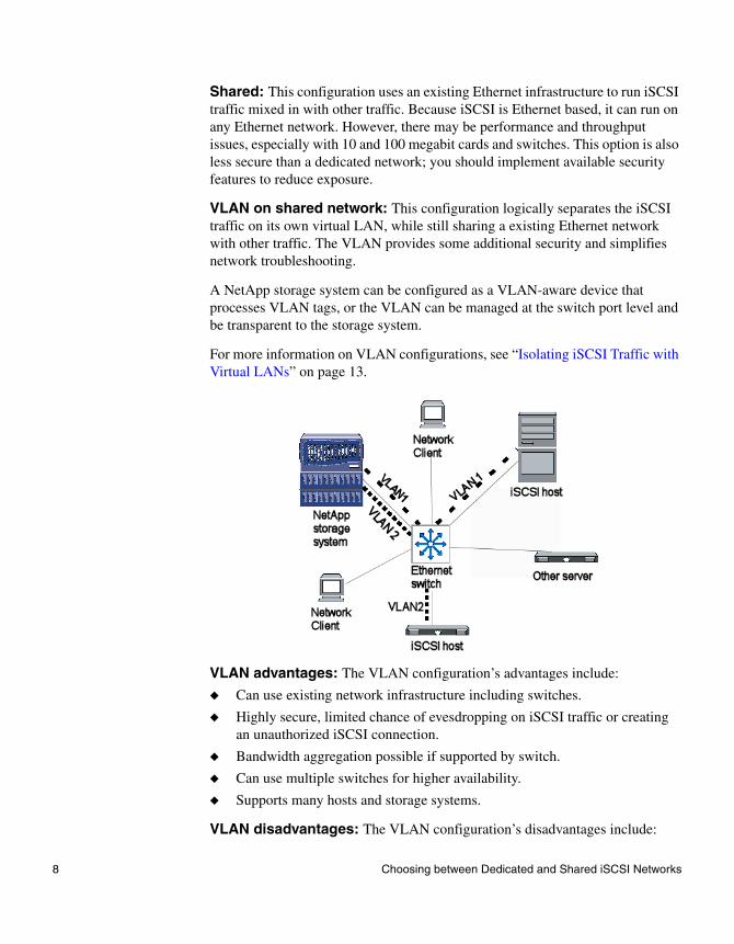
VLAN on shared network: This configuration logically separates the iSCSI traffic on its own virtual LAN, while still sharing a existing Ethernet network with other traffic. The VLAN provides some additional security and simplifies network troubleshooting.
A NetApp storage system can be configured as a VLAN-aware device that processes VLAN tags, or the VLAN can be managed at the switch port level and be transparent to the storage system.
For more information on VLAN configurations, see “Isolating iSCSI Traffic with Virtual LANs” on page 13.
VLAN advantages: The VLAN configuration’s advantages include:
◆ Can use existing network infrastructure including switches.
◆ Highly secure, limited chance of evesdropping on iSCSI traffic or creating an unauthorized iSCSI connection.
◆ Bandwidth aggregation possible if supported by switch.
◆ Can use multiple switches for higher availability.
◆ Supports many hosts and storage systems.
VLAN disadvantages: The VLAN configuration’s disadvantages include:
8 Choosing between Dedicated and Shared iSCSI Networks

◆ Network bandwidth available to iSCSI is limited by other network traffic, unless the host and storage system connect to the same switch.
◆ More expensive, VLAN capable switches are required.
◆ Configuration and administration more complex than separate network.
Public LAN: It is possible to run iSCSI traffic over an existing public LAN. This configuration assumes that the existing network has sufficient bandwidth and switch ports available.
Public LAN advantages: The public LAN configuration’s advantages include:
◆ Can use existing network infrastructure including switches.
◆ Bandwidth aggregation possible if supported by switch.
◆ Can use multiple switches for higher availability.
◆ Supports many hosts and storage systems.
◆ Can use less expensive switches than are required for VLANs.
Public LAN disadvantages: The public LAN configuration’s disadvantages include:
◆ Less secure than other network configurations.
◆ Configuration and administration more complex than direct configuration.
◆ Network bandwidth available to iSCSI is limited by other network traffic.
Chapter 2: Maximizing iSCSI Security 9

Best practices NetApp recommends a network topology that minimizes the risk of unauthorized access to data or modification of data as it traverses the network. You can limit access to data this through the use of direct cabling, switched network environments, virtual LANs (VLANs), and dedicated storage network interfaces where appropriate.
If possible, use a separate, dedicated Ethernet network to carry iSCSI traffic. If you decide to use a shared network instead, then use VLANs to isolate the iSCSI traffic to its own VLANs.
If the network carrying iSCSI traffic connects to other networks, use a firewall to block TCP port 3260 into and out of the iSCSI network.
Finally, hosts that access iSCSI storage resources should be carefully configured, secured, and monitored for unauthorized access. If an attacker compromises an authorized iSCSI host system, there is nothing that any storage system can do to distinguish the attacker from an authorized user.
10 Choosing between Dedicated and Shared iSCSI Networks

Configuring the Storage System for Security
Introduction There are some specific settings that must be configured and actions that must be taken on the storage system in order for iSCSI to function. These required settings and actions enable the iSCSI protocol, allow a host to establish an iSCSI session with the storage system, and allow the host to access one or more LUNs on the storage system.
There are also some optional security settings that will make it increasingly difficult for an unauthorized host to access the storage system. Though not part of the iSCSI specification, the IPsec encryption protocol can be enabled to help improve data integrity and prevent the interception of data being transmitted between an authorized host and storage system.
Disable iSCSI on unused interfaces
On the storage system, disable the iSCSI service on network interfaces that you do not plan to use for iSCSI sessions. Once disabled, the service rejects subsequent attempts to establish new iSCSI sessions over an interface.
You can disable interfaces using the iswt interface disable command (Data ONTAP versions 7.0.x and earlier) or the iscsi interface disable command (Data ONTAP versions starting with 7.1). You can also use the FilerView interface.
Change default initiator security to deny
To ensure that only authorized initiators access resources on the storage system, change the default security method to deny. Initiators that have an explicit security setting are not affected by this command. All initiators not in the list of initiators are unable to establish a session with the storage system when the default security method is set to deny.
The command to set this default is iscsi security default -s deny.
Set security for individual initiators
Once you set the default initiator security method to deny, you must explicitly allow the initiators that you do want to be able to access the storage system. You can choose one of three security settings for each initiator:
◆ none - The storage system does not require authentication for the initiator in order to establish a session. Even though a session can be established, LUN
Chapter 2: Maximizing iSCSI Security 11

masking still applies. The initiator can access only LUNs in an igroup that also contains the initiator.
◆ deny - The initiator is denied access to the storage system. No session will be established between the initiator and the storage system regardless of igroup membership.
◆ CHAP - The Challenge Handshake Authentication Protocol is used when establishing a session between the initiator and storage system. CHAP provides encrypted authentication protection. There are two CHAP configurations available:
❖ One-way CHAP authentication. The storage system requests CHAP authentication from the initiator only.
❖ Bidirectional (mutual) CHAP authentication. The storage system requests CHAP authentication from the initiator, and the initiator requests CHAP authentication from the storage system.
Best practices for the storage system
In a direct attached or dedicated switched iSCSI environment, the default settings on the target storage system are usually sufficient. The initiator security method list is empty and the default Data ONTAP security method is none. This means that CHAP is not used and that a session between an initiator and target is established if requested by the initiator.
In a shared (mixed) environment where security is more of a concern, the following is recommended:
◆ To ensure that only authorized initiators access resources on the filer, first change the default security method for Data ONTAP to deny.
◆ Create individual entries in the initiator security method list; specifying CHAP or none as appropriate.
All initiators in the initiator security method list are not affected by the default Data ONTAP setting. They will behave based on their individual security method setting which is set on a per initiator basis. All initiators not in the initiator security method list will be unable to establish a session with the target as a result of the default security method being set to deny.
12 Configuring the Storage System for Security

Isolating iSCSI Traffic with Virtual LANs
VLAN definition A virtual LAN (VLAN) consists of a group of switch ports, potentially across multiple switch chassis, grouped together into a broadcast domain. IEEE 802.1Q specifies the method for identifying and tagging packets for VLANs to enable traffic destined for multiple VLANs to be carried over a single link.
Hard and soft VLANs
There are two types of VLAN segmentation, hard and soft VLANs.
Hard VLANs: Hard VLANs have the following characteristics:
◆ Port based - The VLAN is defined by specifying the switch port identifiers. In other words the switch and switch port (for example, switch 3 port 4, switch 1 port 5) are used to define the VLAN members.
◆ Security - Hard VLANs are generally considered to offer improved security since it is not possible to defeat VLANs using MAC spoofing. However, if an attacker has physical access to the switch simply replacing a cable and reconfiguring the network address can allow access when hard VLANs are used.
◆ Manageability - In many environments hard VLANs are easier to create and manage because only the switch and port identifier need to be specified, instead of the 48-bit MAC address. In addition, hard VLANs lend themselves to labeling of switch port ranges with the VLAN identifier.
Soft VLANs: Soft VLANs have the following characteristics:
◆ Media Access Control (MAC) address based - The VLAN is defined by specifying the MAC address of the members to be included within the VLAN.
◆ Flexibility - Because access is not determined by where the device is physically plugged into the switch, it is possible with soft VLANs to simply move a cable from one port to another without needing to reconfigure the VLAN. This can very useful in troubleshooting situations.
Reasons for implementing VLANs
There are multiple reasons for using VLANs. Generally, it makes more sense with larger IP SANs and general network infrastructures. Here are some of the most significant reasons to implement VLANs:
Chapter 2: Maximizing iSCSI Security 13

◆ Security - Because VLANs limit access between different nodes of an IP SAN, security is increased. VLANs enable leveraging an existing Ethernet infrastructure while still providing enhanced security.
◆ Problem reduction/isolation - The most compelling reason to implement VLANs is that it improves SAN reliability by isolating many of problems that can occur and helps to reduce problem resolution time by limiting the problem space.
◆ Limit available paths - To help reduce unauthorized LUN access from hosts, only specified paths between a host and a particular LUN should be visible. If a host does not have a multi-pathing solution installed, it is typically necessary to ensure that only one path to a LUN is visible to avoid problems. VLANs are the correct tool to reduce the number of available paths to a particular iSCSI target port.
Best practices for VLANs
There is not a simple answer to the hard versus soft VLAN question. The correct choice typically depends on one or more of the following factors:
◆ Are VLANs already being implemented within your current network infrastructure? If the answer is yes, then any VLANs used by an IP SAN will typically match those already in place within the greater network. The IT staff will typically choose the VLAN type they are used to.
◆ Soft VLANs are attractive if you have a dedicated IP SAN infrastructure separate from your general network, where security is usually easier to manage, and fewer threats are expected. This will help mitigate the potential of MAC spoofing. As mentioned above this is possible with soft VLANs. In addition if a relatively small number of VLAN ports are involved, managing MAC address lists required with soft VLANs will not be an issue. Since soft VLANs do not require you to use specific switch/port identifiers, they are better suited for trouble shooting.
◆ Hard VLANs are attractive if you want to rule out MAC spoofing. Hard VLANs are usually easier to manage, especially with relatively high port counts and/or MAC address changes, since you do not have to deal with MAC address tracking issues.
14 Isolating iSCSI Traffic with Virtual LANs

Authenticating Hosts and Storage Systems using CHAP
CHAP overview The Challenge Handshake Authentication Protocol (CHAP) is an authentication protocol that is used to authenticate iSCSI initiators at target login and at various random times during a connection. The CHAP specification is RFC 1994, available from www.ietf.org.
Note that CHAP provides authentication, not encryption. Using CHAP does not affect the data being transmitted.
How CHAP works When you configure CHAP, the host and storage system authenticate each other as follows:
1. The initiator attempts to establish an iSCSI session with the target.
2. The target responds with a CHAP challenge: send me your 128-bit MD-5 hash value based on your CHAP password. Note that the actual password is not sent over the wire. The session has not yet been established.
3. The initiator sends a 128-bit MD-5 hash value. The target compares the hash value received from the host with the hash value it calculates from the password listed for initiator. If the values match then the iSCSI session is established. If the values do not match, then the session is refused.
4. If you specify bidirectional (mutual) CHAP, the initiator then challenges the target, and the target responds as above before the session is established.
Note that the target will periodically challenge the host after the session has been established to make sure that an imposter has not inserted itself in place of the host. If the periodic challenge fails, the session is dropped.
CHAP user names and passwords
The storage system must be configured with the CHAP user name and password of each initiator. For bidirectional (mutual) CHAP, each initiator must be configured with the CHAP user name and password of the target.
Chapter 2: Maximizing iSCSI Security 15

Best practices for CHAP
Use CHAP whenever the hosts and storage systems are on a shared network. CHAP does not add any significant value in a dedicated network configuration.
When assigning CHAP passwords to initiators, it is important to record the passwords for use when configuring the iSCSI host systems. The username and password used on the storage system must match those used on the host initiator.
Be sure to check the support kit or host operating system documentation for host-specific CHAP rules. For example:
◆ The Microsoft Windows software initiator requires an ASCII text password of 12 to 16 bytes without IPsec, or 2 to 16 bytes with IPsec.
◆ The IBM AIX software initiator always uses the AIX host name as its CHAP user name, and does not support bidirectional CHAP.
16 Authenticating Hosts and Storage Systems using CHAP

Limiting Access to LUNs with LUN Masking
Overview LUN masking allows only specified initiators to access specified LUNs. LUN masking provides some security as well as reducing the risk of data corruption. The storage system implements LUN masking using initiator groups, or igroups.
Creating igroups You typically create an initiator group for each host that can access LUNs. The igroup contains the initiator node name or names of the host. When you create LUNs for that host, you map the LUNs to the host’s igroup. Once a LUN is mapped to an igroup, only the initiators in that igroup can access the LUN.
Be aware that a host could impersonate the initiator node name of another host. Therefore, LUN masking is not a sufficient security mechanism when the storage system is on a network that can be accessed by unauthorized hosts.
Using clustered hosts
If you have clustered hosts, all of the hosts in the cluster need access to all of the LUNs. Therefore, you need to create an igroup that contains all of the initiators in the cluster.
The host clustering software is responsible for ensuring that only one host writes to any given LUN at a time. If two hosts try to write to the same LUN without being managed by clustering software, the LUN data is likely to be corrupted.
Best practices Each host should be in its own igroup, unless the hosts are clustered. Clustered hosts must be managed by clustering software that prevents multiple hosts from writing to the same LUN.
When you create igroups on the storage system, be sure to specify the correct protocol (iSCSI or FCP) and the correct host operating system.
Chapter 2: Maximizing iSCSI Security 17

Encrypting Data Transmission using IPsec
Overview If your iSCSI traffic flows over a public network, and you are concerned about the data being intercepted, you can choose to encrypt the data using the IPsec protocol. There are two modes of IPsec, transport mode and tunnel mode. IPsec also provides authentication that is superior to CHAP.
RFC 3723, Securing Block Storage Protocols over IP, defines IPsec. You can get this standard from www.ietf.org.
Using IPsec transport mode
Transport mode is the typical way of implementing IPsec. The IPsec processing is done by the host and storage system and severely impacts their CPU loads. NetApp offers an IPsec add-on card for the storage system that does the processing, but the encryption still has a heavy impact on the storage system.
Using IPsec tunnel mode
An alternate method is to set up an IPsec tunnel. The iSCSI host and target do not perform any IPsec processing. Instead it is done by an IPsec gateway or router.
Note that the tunnel mode does not offer any IPsec protection between the host/target and its IPsec gateway. The traffic is only encrypted between the gateways. The network between the gateways is assumed to be the unsecure part of the network.
18 Encrypting Data Transmission using IPsec

Even though there is no CPU overhead on the host and target, there is still increased latency of the network traffic because the frames need to be processed by the IPsec routers.
Best practices for IPsec
IPsec does not add significant value in a dedicated network configuration.
Whenever the hosts and storage systems are on a shared network, consider using IPsec for data that requires the highest level of security. An IPsec configuration should be prototyped and tested to verify that performance meets requirements. Consider using a dedicated network instead.
Chapter 2: Maximizing iSCSI Security 19

20 Encrypting Data Transmission using IPsec

Chapter 3: Increasing iSCSI storage availability
3
Increasing iSCSI storage availabilityTopics in this chapter
This chapter contains the following availability topics:
◆ “Clustering Hosts” on page 22
◆ “Clustering Storage Systems” on page 23
◆ “MetroCluster Configurations” on page 25
◆ “Multiple network paths” on page 30
◆ “Header and data digests” on page 36
Eliminating single points of failure
Electrical and mechanical components can always fail. The way you achieve high availability is by eliminating single points of failure in your environment. That way, when an individual component does fail, the overall system continues to be available to users.
The three major parts of an iSCSI configuration are the hosts, the network, and the storage systems. Clustered hosts and storage systems, connected through multiple network paths, can eliminate single points of failure.
21

Clustering Hosts
Overview The host systems are a potential point of failure in any iSCSI configuration. Clustered hosts that can take over for each other in case of a software or hardware failure can eliminate the host as a single point of failure.
Operating system differences
The number of host nodes depends on the host operating system. For example, Microsoft Windows 2003 allows up to 8 nodes. In a Windows host cluster, iSCSI LUNs can be used for both the shared data disks and the quorum disk.
Other host operating systems have different limits. Not all host clustering solutions have been qualified by NetApp. Be sure to check the iSCSI Host Compatibility Matrix to verify that your clustering solution has been qualified. The matrix is available at: http://now.netapp.com/NOW/knowledge/docs/san/fcp_iscsi_config/iscsi_support_matrix.shtml.
Host clustering and LUNs
Each node in a host cluster must be able to see all of the LUNs it uses, either normally, or when standing in for another node. That means the storage system is configured to allow at least two nodes access to any given LUN.
If two hosts try to write to the same LUN without some coordination, data corruption is almost certain. The host clustering software is responsible for coordinating access to each LUN and ensuring that multiple hosts do not overwrite each others’ changes.
When configuring LUNs for clustered hosts, the initiator group for the LUN must contain the initiator node names of all hosts that may need access to that LUN.
Best practices for host clustering
If your availability requirements do not allow host downtime, use a clustered host solution. Be sure that your application works in a clustered environment. Select a host cluster solution that has been qualified with your version of Data ONTAP.
22 Clustering Hosts

Clustering Storage Systems
CFO overview Many NetApp storage systems can be configured in clusters, also called high-availability (HA) pairs. This high-availability feature, called Cluster Failover (CFO), reduces the amount of time which data is unavailable due to the failure of a single storage system. CFO applies to the iSCSI target mode operation of a storage system, just as it does for other network protocols.
NoteNetApp is changing its high-availability terminology to avoid confusion with host clustering. The term Cluster Failover is being replaced with Controller Failover. Clustered storage systems are being renamed high-availability pairs. For example, the FAS900 series uses the C suffix to identify a storage system cluster, such as the FAS980C. The FAS3000 series uses the term Active/Active Configuration to identify what this paper calls a storage system cluster.
When one storage system fails, the other storage system (the takeover storage system) detects the failure, assumes the transport-level iSCSI target device identity of its failed partner, and begins servicing iSCSI requests intended for the failed storage system. Components of the failed storage system's iSCSI identity which are assumed by the takeover storage system include the iSCSI nodename, LUN mapping, CHAP authentication configuration, and the IP addresses and TCP port numbers by which the failed storage system was accessible. From the initiator's point of view, the storage system which failed simply becomes available again after a short period of time; the initiator is unaware of the fact that the cluster partner is operating in takeover mode, servicing requests on behalf of the failed storage system.
Takeover mode When operating in takeover mode, a storage system operates in a dual role, both as itself (the local storage system) and on behalf of the failed partner storage system. An iSCSI session is assigned to one of the two storage systems (local or partner), based on the storage system network interface and IP address over which TCP connection is being conducted. iSCSI sessions for the local storage system use the storage system's own set of LUN objects and per-initiator LUN maps; sessions for the partner storage system use the partner storage system's LUNs and maps.
Chapter 3: Increasing iSCSI storage availability 23

When the failed storage system reboots and is ready to resume operating on its own behalf, the system administrator performs a CFO 'giveback' operation. The takeover storage system terminates any iSCSI sessions it is operating on behalf of its partner, relinquishes its partner's identity, and stops accepting new iSCSI login requests for its partner. The previously failed storage system completes its boot sequence and begins accepting new iSCSI login requests and serving data through its iSCSI service.
In summary, these three events are virtually indistinguishable from the point of view of an initiator (other than possible variations in the length of unavailability):
◆ Unclustered storage system reboot
◆ CFO takeover
◆ CFO giveback
In all cases, an iSCSI session is lost, and the target becomes unavailable. After some period of time, the target becomes available again, with the same iSCSI nodename, and at the same IP addresses and TCP port numbers. Because the storage system supports only ErrorRecoveryLevel=0, the initiator must perform session-level recovery following any period of loss of connectivity.
Best practices for clustered storage systems
To ensure availability of the underlying storage in your environment, you should use HA storage systems. Because the two “heads” in the HA solution run in an active-active configuration, all of your storage resources are in use; you do not have to purchase “standby” hardware that is rarely used.
The two storage system heads must be the same model, and should be configured identically: use the same cards in the same slots, use consistent naming, and connect corresponding ports to the same subnets.
24 Clustering Storage Systems

MetroCluster Configurations
Overview A MetroCluster configuration is an integrated high availability and business continuance solution designed for the campus and metropolitan area. MetroCluster is designed to tolerate site specific disasters with minimal interruption to mission critical applications and zero data loss by synchronously mirroring data between two sites.
In the event of a disaster affecting a data center, MetroCluster enables you to quickly and easily failover the mission critical operation to another data center at a remote site and resume operation with no data loss and minimal administrator intervention. The takeover process only takes minutes and imposes no disruption to users.
Using SyncMirror™ software and a cluster configured for mirrored volumes, a MetroCluster solution enables access to data even after complete loss of one of the clustered nodes. The nodes can be up to 30 kilometers apart.
MetroCluster components
A MetroCluster solution includes the following software components:
◆ Clustered failover - provides the high availability failover capability between storage systems at the primary and remote sites; the site failover decision is controlled by administrator using a single command.
◆ SyncMirror - provides an up-to-date copy of data at the remote site; data can only be accessed by the remote storage system after failover.
◆ ClusterRemote - provides a mechanism for administrator to declare a site disaster and initiate a site failover to the remote site.
Fibre Channel switch requirements
If the primary and remote sites are more than 500 meters apart (300 meters for 2-gigabit Fibre Channel connections), dedicated Fibre Channel switches are required at each site to enable the long distance connectivity between sites. For shorter distances, Fibre Channel switches are not required.
The following figure shows the basic components of a switched fabric MetroCluster configuration.
Chapter 3: Increasing iSCSI storage availability 25

Cluster types and their advantages
The MetroCluster is a special case of a clustered storage system. Clusters can be one of the following types:
Standard cluster (non-MetroCluster): A standard cluster contains two sets of Fibre Channel disk shelves, a local node, and a partner node. Both nodes must be identical storage systems. The Data ONTAP software in each node monitors the functioning of its partner node using a heartbeat signal. Data from the NVRAM of one node is mirrored by its partner. Either node can take over the partner's disks if the partner fails.
The two nodes in a cluster can be separated from each other by as much as 500 meters. Systems operating at 2-gigabit Fibre Channel allow a maximum node separation distance of 300 meters.
The advantages of having a standard cluster are as follows:
◆ Data continues to be processed if one of the nodes fails and cannot reboot.
◆ Data continues to be processed if an adapter on a node fails.
◆ System maintenance can be performed without interrupting service.
◆ In any of these situations, the takeover node continues to serve data until the problem is corrected.
Non-switched MetroClusters and mirrored clusters: Non-switched MetroClusters and mirrored clusters contain two complete copies of specified data volumes and file systems. These copies are called plexes and are continuously and synchronously updated every time Data ONTAP writes data to the disks. Plexes are physically separated from each other across different groupings of disks.
26 MetroCluster Configurations
During configuration of the cluster, Data ONTAP identifies spare disks and divides them into separate groupings called pools. These pools of disks are physically separated from each other, allowing for high availability of mirrored volumes. When you add a mirrored volume or add disks to one side of a mirrored volume, Data ONTAP determines how much storage you need for the second half of the mirror, and dedicates that storage from a separate pool to the mirrored volume.
The advantages of having duplicate copies of your data are as follows:
◆ Mirrored data on your cluster survives a multiple disk failure within your volume.
◆ Mirrored data on your cluster survives a double disk error in a RAID group with a single parity disk (non-RAID-DP). This would cause a loss of the volume on non-mirrored volumes.
◆ Mirrored data on your cluster survives if one part of the cluster loses connectivity to your disks.
◆ Mirrored data on your cluster survives if your cluster loses connectivity to remote storage.
◆ Mirrored data on your cluster survives the destruction of a mirrored site or destruction of connectivity to the remote site.
In any of these failure situations, the surviving mirrored plex continues to serve data until the problem is corrected.
Fabric-attached MetroCluster: A fabric-attached MetroCluster contains two fabrics. A switch fabric consists of a switch on the local half of the cluster connected to a switch on the remote half of the cluster. The two switches are connected to each other through long distance interswitch link (ISL) cables.
The advantages of fabric-attached MetroClusters are the same as those of both standard and mirrored clusters. In addition, fabric-attached MetroClusters have the following advantages:
◆ Expanded distance between nodes of the cluster up to 30 kilometers.
◆ Disk shelves and nodes are not connected directly to each other, but are connected to a fabric with multiple data routes, ensuring no single point of failure.
Chapter 3: Increasing iSCSI storage availability 27

Microsoft Exchange example
The following figure shows an example of a fabric-attached MetroCluster configuration that supports a Microsoft Exchange environment.
28 MetroCluster Configurations

Best practices for MetroCluster
Use a MetroCluster configuration when you must protect against failures that could affect both nodes of a standard storage system cluster. You must have two physically separate facilities to locate the members of the MetroCluster.
A MetroCluster configuration should be custom designed for the specific application. Use NetApp ConsultingEdge Services to help plan and implement the MetroCluster.
Chapter 3: Increasing iSCSI storage availability 29

Multiple network paths
Multi-pathing The network connection between a host and storage system is a potential point of failure in an iSCSI configuration. Using multiple paths can eliminate these connections as a single point of failure. Potential failures include:
◆ Host hardware failure, including cable pull and host NIC or HBA failure.
◆ Target hardware failure, including cable pull and target interface failure.
◆ Connection hardware failure, including switch failure and power loss.
In addition to the high availability benefits, the presence of multiple paths allows higher throughput to the storage system, eliminating the limit imposed by a single data path. This is known as bandwidth aggregation.
Multi-pathing choices for an iSCSI network include:
◆ Link aggregation, also known as trunking or teaming.
◆ Multi-connection sessions.
◆ Multi-path I/0 (MPIO).
How multi-pathing works
In a multi-pathing environment, a multi-pathing technology (MPT) layer sits between the disk driver and the host bus adapters or iSCSI software initiators. This MPT layer serves as a clearinghouse for LUNs and paths, cataloging all of the individual LUN paths, recognizing the existence of multiple paths to the same physical LUN, and presenting a virtualized set of unique LUNs to the disk driver and upper layers.
When the MPT layer receives SCSI requests directed to one of the virtualized LUNs, it selects one of the available physical paths on which to send the request to the physical LUN. Note that the individual adapter drivers are generally unaware of the presence of the multi-pathing technology.
Different multi-pathing solutions fit into different places in the storage stack, as shown in the following sections.
Link aggregation Link aggregation is the technique of taking several distinct Ethernet links and making them appear as a single link. The IEEE 802.3ad specification describes link aggregation.
30 Multiple network paths

Traffic is directed to one of the links in the group using a distribution algorithm. This technology is referred to by many names, including channel bonding, teaming, and trunking. Link aggregation is not storage specific. The following figure shows where link aggregation fits into the storage stack.
Link aggregation implementations typically support active-passive and active-active path selection algorithms. However, it should be noted that for active-active configurations where both (or multiple) paths are used simultaneously, the same path is always selected for a given destination endpoint to avoid out of order delivery. This fact means that the link aggregation does not increase the throughput above the capability of a single path for a connection between a single host and storage system.
Link aggregation pros include:
◆ Transparent to all network protocols - The advantages of link aggregation are shared not just with iSCSI but other network traffic such as NFS.
◆ Well known mature technique.
◆ Available on both host and storage systems (VIFs).
Link aggregation limitations:
◆ Aggregated interfaces must be connected to the same network, often the same switch or card within a switch, limiting the physical isolation of the multiple paths.
◆ Dependent on having aggregation capable drivers and switches.
Disk class driver
SCSI layer
iSCSI initiator
TCP/IP
NIC driver (GbE)
To application
To storageappliance
Trunking-capable driver
NIC NIC
1 TCP connection
2 available transport paths
Chapter 3: Increasing iSCSI storage availability 31

◆ Not possible to get aggregated throughput for a single host to single storage system.
◆ Does not work with hardware iSCSI initiators (HBAs).
Multi-connection sessions
Multi-connection sessions are an optional part of the iSCSI specification. They create the multiple paths starting at the iSCSI session layer of the storage stack. Both the iSCSI initiator (host) and iSCSI target (storage system) need to support multi-connection sessions in order to configuration sessions with multiple connections.
The following figure shows where iSCSI multi-connection sessions fit into the storage stack.
Currently, multi-connection sessions are supported only by the Microsoft iSCSI software initiator v2.0 and Data ONTAP 7.1. Refer to the NetApp iSCSI support matrix for the most up to date information regarding supported ONTAP and initiator releases.
iSCSI HBAs do not currently support multi-connection sessions. With a software initiator multi-connect sessions can be combined with link aggregation where each connection is made across an aggregated link.
Disk class driver
SCSI Layer
TCP/IP
NIC driver
NIC
TCP/IP
NIC driver
NIC
iSCSI Initiator
To storage appliance
32 Multiple network paths

Multi-connection session pros:
◆ No dependency on an aggregation-capable Ethernet infrastructure.
◆ Part of the iSCSI specification.
◆ No extra vendor multi-pathing technology layer required.
Multi-connection session limitations:
◆ Requires initiator and target sophistication.
◆ Support for initiator HBAs not likely in the short term.
MPIO Multi-path I/O (MPIO) inserts a separate multi-pathing layer in the storage stack. The following figure shows the storage stack.
There are multiple implementations of this type of multi-pathing on the various operation systems. The MPIO infrastructure offered by Microsoft is the standard way to do MPIO on Windows Server technologies.
With Microsoft's MPIO each storage vendor supplies a device specific module (DSM) for their storage array. The NetApp DSM is included with the SnapDrive™ for Windows software, and requires a separate license. Network Appliance uses the same DSM for FC and iSCSI connected LUNs.
Disk class driver
SCSI layer
iSCSI initiator
TCP/IP
NIC driver
To application
NIC
iSCSI initiator
TCP/IP
NIC driver
NIC
Could be HBAs, or 2 instances of SW initiator
Multi-Pathing Technology Layer (MPT)
To storage appliance
Chapter 3: Increasing iSCSI storage availability 33

The NetApp delivered DSM uses an active-passive algorithm on a per LUN basis. For a single LUN all I/O uses a single path until a failure occurs. However, the LUNs are round robined across the available paths. For example, if there are two disks configured, G:\ and H:\, I/O from disk G:\ will utilize one path and disk H:\ will utilize the second path. This all allows the full available bandwidth to be utilized as long as multiple LUNs are configured.
When used with a software iSCSI initiator, MPIO can be combined with link aggregation where each path uses an aggregated link.
MPIO pros:
◆ No dependency on an aggregation-capable Ethernet infrastructure.
◆ Mature implementation.
◆ Supports software and hardware initiators (HBAs).
MPIO limitations:
◆ Extra vendor multi-pathing technology layer required.
Best practices for host-side multi-pathing
If your configuration uses iSCSI HBAs then use MPIO.
If your configuration uses software initiators, you can choose either MPIO or multi-connection sessions.
The following table summaries the trade-offs.
Link aggregation MPIO
Multi-connection session
Improves bandwidth between a single server and a single storage system
No Yes Yes
Improves bandwidth between multiple hosts and a single storage system
Yes Yes Yes
Supports completely physically independent paths
No Yes Yes
Supports iSCSI HBAs No Yes No
34 Multiple network paths

Supplies multi-pathing benefits to other TCP/IP traffic such as NFS
Yes No No
iSCSI initiator support required No No Yes
iSCSI target support required No No Yes
Link aggregation MPIO
Multi-connection session
Chapter 3: Increasing iSCSI storage availability 35

Header and data digests
Digest overview The iSCSI specification mandates that iSCSI targets and initiators support the use of Digests. Digests are simply a 32-bit CRC checksum mechanism to determine the integrity of the header and data contained in the iSCSI Protocol Data Units (PDUs). Support is mandatory, but use of the feature for a given iSCSI session is optional. The initiator and target can independently negotiate the use of digests for PDU headers and PDU data segments. You can choose to use header digests only, data digests only, or both header and data digests.
No storage system configuration is needed to enable the use of digests on a per-session basis. The target uses the digest setting specified by the initiator during the login sequence.
Digest security Digests provide no header or data encryption of any kind. Digests can be seen as providing a very limited form of security. If a PDU header is tampered with the header digest checksum will not match resulting in the dropping of the header and retransmitting the SCSI-3 command from the beginning. If a PDU data segment is tampered with the data digest checksum will not match resulting in a retransmission of that PDU.
Data integrity Data integrity is the driving force behind the use of digests. Because iSCSI uses TCP/IP, iSCSI derives the benefits of TCP's checksum/retry mechanism. However, iSCSI digests were implemented in order to increase reliability above that of TCP.
Digests and error recovery level
iSCSI error recovery level 1 requires that data digests be enabled to be useful. Without data digests, error recovery level 1 is functionally equivalent to error recovery level 0. However, error recovery level 2 provides real benefits without enabling header or data digests.
Note that iSCSI Error Recovery Level 1 requires that Data Digests be enabled to be useful. Without Data Digests, Error Recovery Level 1 is functionally equivalent to Error Recovery Level 0. However, Error Recovery Level 2 provides real benefits without enabling header or data digests.
36 Header and data digests

Best practices for digests
Digests should generally not be used. The small gain in reliability does not usually overcome the high CPU costs on the host and storage system.
Enabling iSCSI digests should only be considered when iSCSI traffic between a host and a target must travel over an Ethernet network that is having transmission and error issues.
Using only Header digests can increase transmission overhead by about 10 to 20 percent. Data digest overhead can range between 30 to 70 percent depending on the size of the data segment in the iSCSI PDU.
Chapter 3: Increasing iSCSI storage availability 37

38 Header and data digests