
AirPrime SL Series Universal Dev Kit v30 User Guide-Rev004 0911

IS-DEV KIT-9 User Manual
7850 East Gelding Drive • Scottsdale, AZ 85260-3420
IS-DEV KIT-9 User Manual C.docx Page 1 of 45
Toll Free 1.877.2BUYNKK (877.228.9655) • Phone 480.991.0942 • Fax 480.998.1435 www.nkkswitches.com • Email [email protected] 0717
IS-DEV KIT-9 User Manual Revision C
Firmware Version 1.0
NKK SWITCHES 7850 E. Gelding Drive
Scottsdale, AZ 85260
Toll Free 1-877-2BUYNKK (877-228-9655)
Phone 480-991-0942
Fax 480-998-1435
e-mail <[email protected]>
All Rights Reserved Worldwide
NKK Switches makes no warranty for the use of these products and assumes no responsibility for any errors,
which may appear in this document, nor does it make a commitment to update the information contained herein.
Smart Switch is trademark of NKK Switches.

IS-DEV KIT-9 User Manual
7850 East Gelding Drive • Scottsdale, AZ 85260-3420
IS-DEV KIT-9 User Manual C.docx Page 2 of 45
Toll Free 1.877.2BUYNKK (877.228.9655) • Phone 480.991.0942 • Fax 480.998.1435 www.nkkswitches.com • Email [email protected] 0717
Table of Contents
Table of Contents ..........................................................................................................2
1. General Features .......................................................................................................3
2. Thank You for Purchasing NKK Switches’ Dev Kit ................................................4
3. Preface.......................................................................................................................5
4. Operational Overview ...............................................................................................6
5. Programming the IS-DEV KIT-9 using Universal Communicator 2015 ...............10
6. Operational Details .................................................................................................18
7. Communication Protocol ........................................................................................23
8. Commands to the Controller ...................................................................................24
9. Character Commands for OLED Switches .............................................................32
10. Hardware .................................................................................................................35
11. Key Terms & Definitions........................................................................................40
12. Firmware Issues ......................................................................................................41
Appendix .....................................................................................................................42

IS-DEV KIT-9 User Manual
7850 East Gelding Drive • Scottsdale, AZ 85260-3420
IS-DEV KIT-9 User Manual C.docx Page 3 of 45
Toll Free 1.877.2BUYNKK (877.228.9655) • Phone 480.991.0942 • Fax 480.998.1435 www.nkkswitches.com • Email [email protected] 0717
1. General Features
The IS-DEV KIT-9 is a development kit with two Frameless OLED SmartSwitches (Part #ISF15ACP4). The
CL04 controller is used in this development kit as well as the IS-DEV KIT-7 and IS-DEV KIT-8. The firmware
is different for the IS-DEV KIT-9 and does not work with other switches.
In this document, we refer to the Frameless OLED SmartSwitch as OLED SmartSwitch or OLED switch.
Below are current features:
• IS-DEV KIT-9 controls two OLED (96 x 64) SmartSwitches (ISF15ACP4)
• Pushbutton functionality on each OLED SmartSwitch
o RGB color OLED display with a resolution of 96 x 64 pixels
• Power from USB or 9V power supply. (Power supply not included.)
• On board microSD Flash that can hold up to 65,536 images
• Adjustable audio feedback when a OLED switch is pressed
• Software control setting for 16 levels of brightness designed to extend the life of the OLED
• User programmable for images, attributes and set-ups
• Real-time control by host:
o Commands to direct the controller to display any of 65,535 images to either of the two switches
o Commands to send characters so controller can create images for either of the two switches
o Commands to check various statuses of the controller
o Report switch activities to host
o Report the address of any new image displayed to host
• Stand-alone operation:
o Set up the controller to function based on switch presses
o Set up the controller to function based on timer expiration
o Report switch activities to host
o Report the address of any new image displayed to host
• Communication via USB (115.2K, 1 start bit, 8 bit, 1 stop bit)
• Set the type of activity reports from the controller to host.
• Power requirement: 5V to 12V at 180 mA max
• Controller board firmware can be customized based on customer requirements
IS-DEV KIT-9 User Manual
7850 East Gelding Drive • Scottsdale, AZ 85260-3420
IS-DEV KIT-9 User Manual C.docx Page 4 of 45
Toll Free 1.877.2BUYNKK (877.228.9655) • Phone 480.991.0942 • Fax 480.998.1435 www.nkkswitches.com • Email [email protected] 0717
2. Thank You for Purchasing NKK Switches’ Development
Kit
By purchasing this kit a new horizon of design is expanding before your eyes. The Frameless OLED
SmartSwitch can be the distinguishing feature within your application that sets your product apart from the
competition. This kit contains all the necessary components to get you started using, testing and ultimately
incorporating NKK Switches’ Frameless OLED SmartSwitch into your designs.
The development kits come preprogrammed for demonstration. They can be reprogrammed by the user for
demonstration or real time application. NKK provides a free PC software (Universal Communicator 2015) for
programming the development kits.
There are many documents such as “How to” in the web page below that can be useful.
http://www.nkkswitches.com/SmartSwitch-Engineering-Documentation.aspx
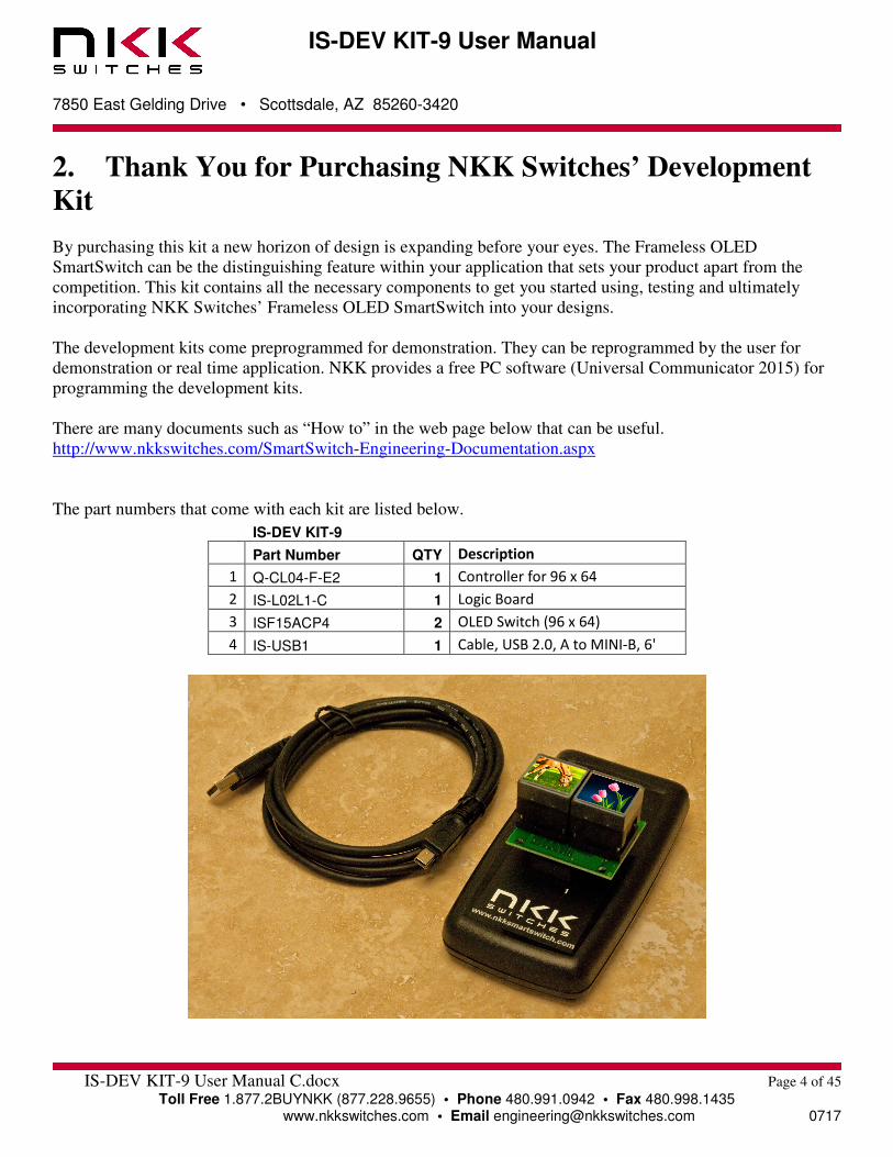
The part numbers that come with each kit are listed below.
IS-DEV KIT-9
Part Number QTY Description
1 Q-CL04-F-E2 1 Controller for 96 x 64
2 IS-L02L1-C 1 Logic Board
3 ISF15ACP4 2 OLED Switch (96 x 64)
4 IS-USB1 1 Cable, USB 2.0, A to MINI-B, 6'

IS-DEV KIT-9 User Manual
7850 East Gelding Drive • Scottsdale, AZ 85260-3420
IS-DEV KIT-9 User Manual C.docx Page 5 of 45
Toll Free 1.877.2BUYNKK (877.228.9655) • Phone 480.991.0942 • Fax 480.998.1435 www.nkkswitches.com • Email [email protected] 0717
3. Preface
The IS-DEV KIT-9 is a development kit designed to demonstrate the features of the Frameless OLED
SmartSwitch as well as facilitate the incorporation of the pushbutton into new application designs. The OLED
SmartSwitch is best used for displaying video or images that change frequently.
This user manual will go through general features and rudimentary commands, like how to download images
and attributes. It then goes into the more technical details regarding how the IS-DEV KIT-9 operates.
Section 4 is the overview of the development kit and how it operates along with features.
Section 5 is written on how to program the development kit using Universal Communicator 2015. This section
was designed for those who wish to simply start using the development kit without getting into the technical
details.
Sections 6, 7, 8 and 9 cover detailed communications and commands between the host computer and the Dev
Kit controller. Section 10 is the hardware and the schematic, and sections 11 and 12 are definitions and
firmware issues. There is also an appendix for understanding hexadecimal.
Universal Communicator 2015
Universal Communicator 2015 can download the images and attributes to the development kit. The 96 x 64
images can be created by any graphic software that can save as 24 color bitmap. The attribute values that
determine how the development kit works can be created in Microsoft Excel or Notes.
The development kit can communicate with any communication software that can perform the communication
protocol. Universal Communicator 2015 is provided as demonstration software.

IS-DEV KIT-9 User Manual
7850 East Gelding Drive • Scottsdale, AZ 85260-3420
IS-DEV KIT-9 User Manual C.docx Page 6 of 45
Toll Free 1.877.2BUYNKK (877.228.9655) • Phone 480.991.0942 • Fax 480.998.1435 www.nkkswitches.com • Email [email protected] 0717
4. Operational Overview
Power-up Sequence: Upon power-up, the controller initializes the OLED screens. It then allows for OLED brightness adjustment.
Note: The switch on top of the controller is not used in the IS-DEV KIT-9 and its position has no effect on the
operation.
OLED Brightness Adjustment Mode: There are 16 levels of brightness 0, 1, 2, 3, 4, 5, 6, 7, 8, 9, A, B, C, D, E, and F where F is the maximum
brightness. The level of brightness is displayed in the middle of image. After power-up, the display is at the
maximum brightness (level F). The controller will allow the brightness of the two OLED modules to be
adjusted. The left OLED displays the brightness level F and the word DIM. The right OLED displays the
brightness F and the word BRIGHT. The left button can be pressed to make both displays dimmer and the right
button makes both displays brighter.
The OLED rated life of 50,000 hours is based on maximum brightness. The dimmer the level is set the longer
the expected life of the OLED. Any switch activity will keep the unit in this mode.
The brightness changes stay in effect for the duration of the session.
After 2.6 seconds of user inactivity the controller will move into the main operations mode.
Main Operational Mode: There are 65,535 addresses (0x0001 to 0xFFFF) to store images and attributes. Upon power-up, as default,
OLED switch one displays the image of address 0x0001 and OLED switch two displays the image of address
0x0010. These addresses are user defined and can be changed. The attributes at the respective address become
the active attributes for each switch. The controller then transmits 11H via USB indicating it is ready for
operation.
The images on the switches change based on:
A. Attribute setting for switch presses
B. Attribute setting for timers
C. Commands via USB
IS-DEV KIT-9 User Manual
7850 East Gelding Drive • Scottsdale, AZ 85260-3420
IS-DEV KIT-9 User Manual C.docx Page 7 of 45
Toll Free 1.877.2BUYNKK (877.228.9655) • Phone 480.991.0942 • Fax 480.998.1435 www.nkkswitches.com • Email [email protected] 0717
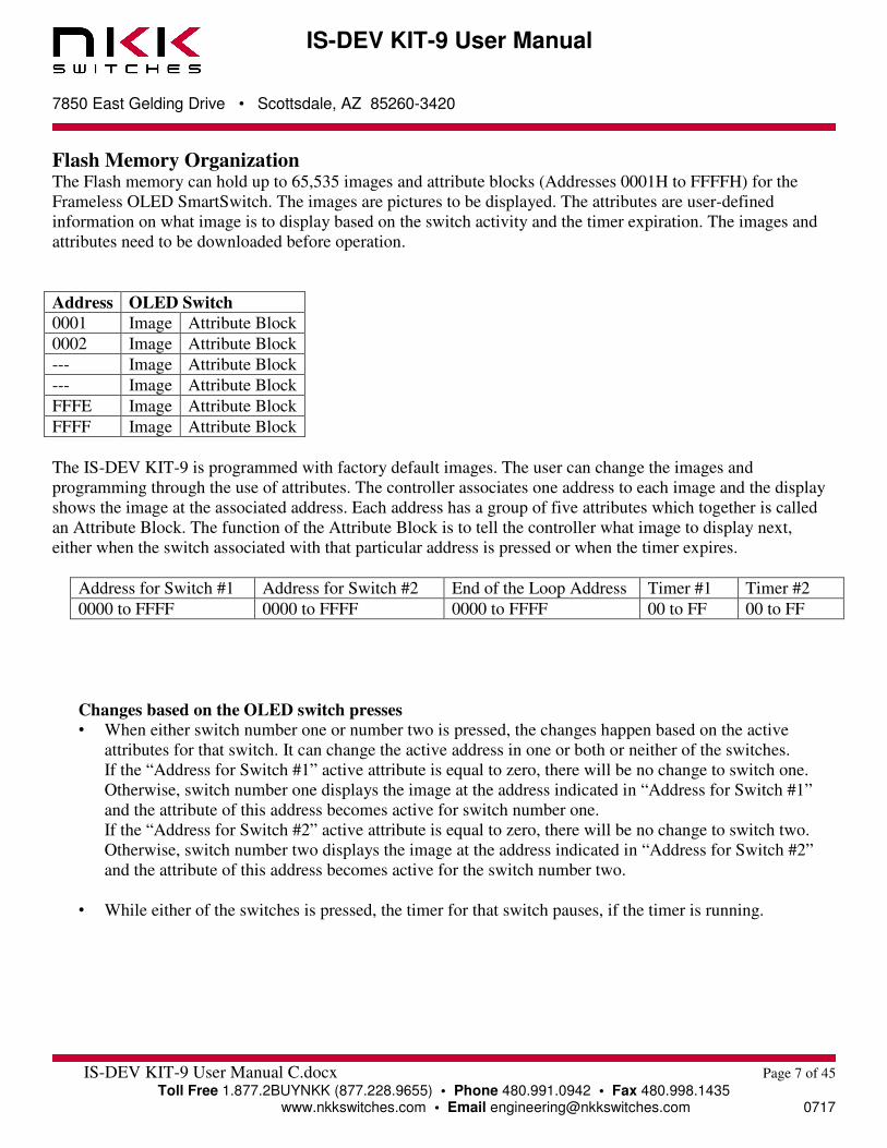
Flash Memory Organization
The Flash memory can hold up to 65,535 images and attribute blocks (Addresses 0001H to FFFFH) for the
Frameless OLED SmartSwitch. The images are pictures to be displayed. The attributes are user-defined
information on what image is to display based on the switch activity and the timer expiration. The images and
attributes need to be downloaded before operation.
Address OLED Switch
0001 Image Attribute Block
0002 Image Attribute Block
--- Image Attribute Block
--- Image Attribute Block
FFFE Image Attribute Block
FFFF Image Attribute Block
The IS-DEV KIT-9 is programmed with factory default images. The user can change the images and
programming through the use of attributes. The controller associates one address to each image and the display
shows the image at the associated address. Each address has a group of five attributes which together is called
an Attribute Block. The function of the Attribute Block is to tell the controller what image to display next,
either when the switch associated with that particular address is pressed or when the timer expires.
Address for Switch #1 Address for Switch #2 End of the Loop Address Timer #1 Timer #2
0000 to FFFF 0000 to FFFF 0000 to FFFF 00 to FF 00 to FF
Changes based on the OLED switch presses
• When either switch number one or number two is pressed, the changes happen based on the active
attributes for that switch. It can change the active address in one or both or neither of the switches.
If the “Address for Switch #1” active attribute is equal to zero, there will be no change to switch one.
Otherwise, switch number one displays the image at the address indicated in “Address for Switch #1”
and the attribute of this address becomes active for switch number one.
If the “Address for Switch #2” active attribute is equal to zero, there will be no change to switch two.
Otherwise, switch number two displays the image at the address indicated in “Address for Switch #2”
and the attribute of this address becomes active for the switch number two.
• While either of the switches is pressed, the timer for that switch pauses, if the timer is running.

IS-DEV KIT-9 User Manual
7850 East Gelding Drive • Scottsdale, AZ 85260-3420
IS-DEV KIT-9 User Manual C.docx Page 8 of 45
Toll Free 1.877.2BUYNKK (877.228.9655) • Phone 480.991.0942 • Fax 480.998.1435 www.nkkswitches.com • Email [email protected] 0717
Changes based on timer settings
• If the input for the Timer #1 = 00H for switch number one, then the timer does not run. Therefore, there
will be no change based on the timer for switch number one. Otherwise, the timers run and the images
change sequentially from the original address (active address) to the address indicated by “End of the
Loop Address”.
The number of milliseconds (ms) each image is displayed is the product of Timer #1 multiplied by
Timer #2. The maximum possible time is 65 seconds. The timer value in ms = (Timer #1) x (Timer #2), Note: if Timer #2 = 0 it counts as 256.
The attributes of the original address (active address) stays in effect and the attributes of all other
addresses are ignored until the end of the loop address is reached.
• Once the end of the loop address is reached, the attributes of this address are checked (does not become
active) and changes can happen based on these attributes as stated below:
1. If the “Address for Switch #2” of the end of the loop attributes is equal to zero, no change to switch
number two. Otherwise, switch number two displays the image at the address of “Address for switch
#2” and the attribute of this address becomes active for switch number two.
2. If the “Address for switch #1” of the end of the loop attributes is equal to zero, then switch number
one loops back to the image of the original address (active address) and the loop starts over.
Otherwise, switch number one displays the image at the address of “Address for switch #1” and the
attribute of this address becomes active for the switch number one.
• The switch number two attributes function in the same manner as described above for switch number
one.
Changes based on commands via USB
There are many commands available to control the OLED switches. They are described in detail in section
7, The Communication Protocol. Below is the list of commands available during operation.
• Command to reset the controller
• Command to check connection
• Command to change brightness of OLED switches
• Command to any of the OLED switches to display any address image
• Command to turn on any row of an OLED switch to any color
• Command to create up to 12 characters with any color from any location in an OLED switch
• Command to turn the display ON/OFF
• Command to write directly to OLEDs
• Command to disable/enable attributes execution based on timer and switch presses
IS-DEV KIT-9 User Manual
7850 East Gelding Drive • Scottsdale, AZ 85260-3420
IS-DEV KIT-9 User Manual C.docx Page 9 of 45
Toll Free 1.877.2BUYNKK (877.228.9655) • Phone 480.991.0942 • Fax 480.998.1435 www.nkkswitches.com • Email [email protected] 0717
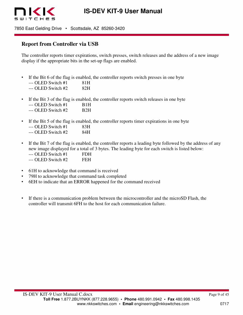
Report from Controller via USB
The controller reports timer expirations, switch presses, switch releases and the address of a new image
display if the appropriate bits in the set-up flags are enabled.
• If the Bit 6 of the flag is enabled, the controller reports switch presses in one byte
--- OLED Switch #1 81H
--- OLED Switch #2 82H
• If the Bit 3 of the flag is enabled, the controller reports switch releases in one byte
--- OLED Switch #1 B1H
--- OLED Switch #2 B2H
• If the Bit 5 of the flag is enabled, the controller reports timer expirations in one byte
--- OLED Switch #1 83H
--- OLED Switch #2 84H
• If the Bit 7 of the flag is enabled, the controller reports a leading byte followed by the address of any
new image displayed for a total of 3 bytes. The leading byte for each switch is listed below:
--- OLED Switch #1 FDH
--- OLED Switch #2 FEH
• 61H to acknowledge that command is received
• 79H to acknowledge that command task completed
• 6EH to indicate that an ERROR happened for the command received
• If there is a communication problem between the microcontroller and the microSD Flash, the
controller will transmit 6FH to the host for each communication failure.
IS-DEV KIT-9 User Manual
7850 East Gelding Drive • Scottsdale, AZ 85260-3420
IS-DEV KIT-9 User Manual C.docx Page 10 of 45
Toll Free 1.877.2BUYNKK (877.228.9655) • Phone 480.991.0942 • Fax 480.998.1435 www.nkkswitches.com • Email [email protected] 0717
5. Programming the IS-DEV KIT-9 using Universal
Communicator 2015
The IS-DEV KIT-9 communicates via USB with any communication software. The commands and protocol
will be explained in sections 6 and 7.
This section covers programming the Dev Kit using the Universal Communicator 2015 without getting into
technical details.
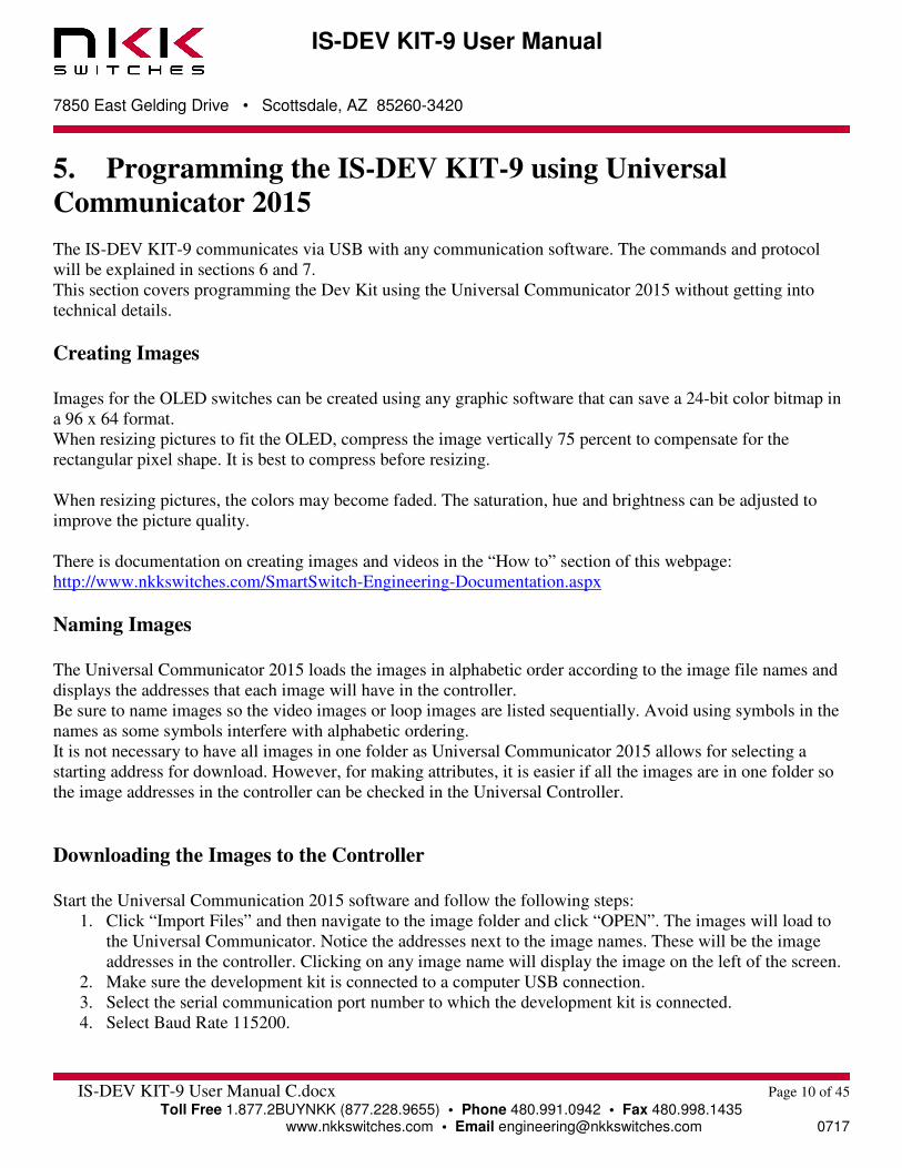
Creating Images
Images for the OLED switches can be created using any graphic software that can save a 24-bit color bitmap in
a 96 x 64 format.
When resizing pictures to fit the OLED, compress the image vertically 75 percent to compensate for the
rectangular pixel shape. It is best to compress before resizing.
When resizing pictures, the colors may become faded. The saturation, hue and brightness can be adjusted to
improve the picture quality.
There is documentation on creating images and videos in the “How to” section of this webpage:
http://www.nkkswitches.com/SmartSwitch-Engineering-Documentation.aspx
Naming Images
The Universal Communicator 2015 loads the images in alphabetic order according to the image file names and
displays the addresses that each image will have in the controller. Be sure to name images so the video images or loop images are listed sequentially. Avoid using symbols in the
names as some symbols interfere with alphabetic ordering.
It is not necessary to have all images in one folder as Universal Communicator 2015 allows for selecting a
starting address for download. However, for making attributes, it is easier if all the images are in one folder so
the image addresses in the controller can be checked in the Universal Controller.
Downloading the Images to the Controller
Start the Universal Communication 2015 software and follow the following steps:
1. Click “Import Files” and then navigate to the image folder and click “OPEN”. The images will load to
the Universal Communicator. Notice the addresses next to the image names. These will be the image
addresses in the controller. Clicking on any image name will display the image on the left of the screen.
2. Make sure the development kit is connected to a computer USB connection.
3. Select the serial communication port number to which the development kit is connected.
4. Select Baud Rate 115200.

IS-DEV KIT-9 User Manual
7850 East Gelding Drive • Scottsdale, AZ 85260-3420
IS-DEV KIT-9 User Manual C.docx Page 11 of 45
Toll Free 1.877.2BUYNKK (877.228.9655) • Phone 480.991.0942 • Fax 480.998.1435 www.nkkswitches.com • Email [email protected] 0717
5. Click the “Port Closed” button to open the communication. If the development kit has the factory default
images and program, the controller will transmit information to the computer which will be displayed in
green font. For example: “83” and “84” will be displayed. The addresses for the images are also
displayed.
6. Click the “Call” button. The computer will send “01” in blue and the controller responds with “61” in
green. This may not be seen if the controller is sending the timer expirations and addresses. However, if
the controller does not send anything, there is likely a problem with the serial connection or set up. It
should be fixed before proceeding.
7. Click “Download Batch”. The controller will respond with “6179” for each image downloaded. Every
image takes 2.5 to 3.5 seconds to download. Universal Communication 2015 will display an error
message if anything is wrong or notify when the download is complete.
8. Leave Universal Communication 2015 open in order to look up the image addresses for creating the
attributes block which determine how the various images are displayed on the OLED switches.
Screen Shot 1, Universal Communicator 2015 with images loaded
IS-DEV KIT-9 User Manual
7850 East Gelding Drive • Scottsdale, AZ 85260-3420
IS-DEV KIT-9 User Manual C.docx Page 12 of 45
Toll Free 1.877.2BUYNKK (877.228.9655) • Phone 480.991.0942 • Fax 480.998.1435 www.nkkswitches.com • Email [email protected] 0717
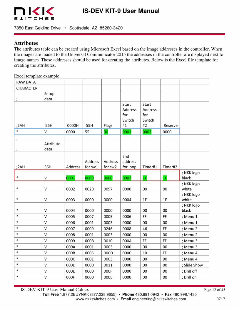
Attributes The attributes table can be created using Microsoft Excel based on the image addresses in the controller. When
the images are loaded to the Universal Communicator 2015 the addresses in the controller are displayed next to
image names. These addresses should be used for creating the attributes. Below is the Excel file template for
creating the attributes.
Excel template example
RAW DATA
CHARACTER
;
Setup
data
;2AH 56H 0000H 55H Flags
Start
Address
for
Switch
#1
Start
Address
for
Switch
#2 Reserve
* V 0000 55 00 0001 0003 0000
;
;
Attribute
data
;2AH 56H Address
Address
for sw1
Address
for sw2
End
address
for loop Timer#1 Timer#2
* V 0001 0000 0000 0002 1F 1F
; NKK logo
black
* V 0002 0020 0097 0000 00 00
; NKK logo
white
* V 0003 0000 0000 0004 1F 1F
; NKK logo
white
* V 0004 0000 0000 0000 00 00
; NKK logo
black
* V 0005 0007 000E 0006 FF FF ; Menu 1
* V 0006 0001 0003 0000 00 00 ; Menu 1
* V 0007 0009 0246 0008 46 FF ; Menu 2
* V 0008 0001 0003 0000 00 00 ; Menu 2
* V 0009 000B 0010 000A FF FF ; Menu 3
* V 000A 0001 0003 0000 00 00 ; Menu 3
* V 000B 0005 000D 000C 10 FF ; Menu 4
* V 000C 0001 0003 0000 00 00 ; Menu 4
* V 000D 0000 0011 0000 00 00 ; Slide Show
* V 000E 0000 000F 0000 00 00 ; Drill off
* V 000F 0000 000E 0000 00 00 ; Drill on
IS-DEV KIT-9 User Manual
7850 East Gelding Drive • Scottsdale, AZ 85260-3420
IS-DEV KIT-9 User Manual C.docx Page 13 of 45
Toll Free 1.877.2BUYNKK (877.228.9655) • Phone 480.991.0942 • Fax 480.998.1435 www.nkkswitches.com • Email [email protected] 0717
Please note the following regarding the template:
1. The first row must have the word “RAW DATA”
2. The second row must have the word “CHARACTER”
3. Any row starting with a semicolon “;” is considered comments
4. Within a row, any data after a semicolon “;” is considered comments
5. The blue block is called Set Up command and is always only one row
6. The red block is called Attribute Block command. There will be many rows of this command.
7. The only fields you need to fill in are highlighted in green above.
Set Up Command There are eight cells for setup command. Only the three cells highlighted in green should be changed. The other
five cells must not be changed.
1. Flags: Do not change flags as it does not affect the stand-alone operation.
2. Start Address for Switch #1: Enter the address for the image you want to be displayed on the left switch (switch
number one) after you turn on development kit. You can check Universal Communicator 2015 for the address of
the image and type it in. The address 0001 has been entered in this template as an example.
3. Start Address for Switch #2: Enter the address for the image you want to be displayed on the right switch
(switch number two) after you turn on development kit. You can check Universal Communicator 2015 for the
address of the image and type it in. The address 0003 has been entered in this template as an example.
Attribute Command Each image address can have an attribute block. However, it is not necessary to create an attribute block for
each image address. There must be a minimum of two attribute blocks (One for switch one start up and one for
switch two start up). The maximum number of attribute blocks is equal to the number of images. One row needs
to be added for each attribute block.
An attribute block needs to be created only for the active address and for the end of the loop address. The
attribute blocks do not have to be in any particular order. If more than one attribute block is created for the same
address, only the last one will be used.
There are eight cells in each attribute block. Only the six cells highlighted in green should be changed. The first
two cells must not be changed.
Upon power-up, switches number one and two display the images at the start addresses from the setup
command. The attributes for these addresses become active attributes for the two switches. Therefore, at
minimum, attribute blocks need to be created for the two switches.
Attribute blocks must be created for any new address the switches are to display due to switch presses or end of
the loop jump. Only the first and last image address of videos or slide shows must have attribute blocks. There
is no need to create attribute blocks for the middle images.
IS-DEV KIT-9 User Manual
7850 East Gelding Drive • Scottsdale, AZ 85260-3420
IS-DEV KIT-9 User Manual C.docx Page 14 of 45
Toll Free 1.877.2BUYNKK (877.228.9655) • Phone 480.991.0942 • Fax 480.998.1435 www.nkkswitches.com • Email [email protected] 0717
Creating Attribute Blocks and Deciding Input Values:
1. Address: This is the address of the attribute block associated to the image. The first two attribute blocks
created are the startup addresses in the setup command. Type in the address.
2. Address for sw1: If the switch that has this attribute block as the active attribute is pressed, and the input address
in this cell is not equal 0000, then the image of the address input in this cell and attribute associated to this address
will be displayed on switch number one. This means an attribute block needs to be created for this address. Please
note, if 0000 is input, it means the image on switch number one will not change when the switch is pressed. If no image change is desired for switch number one, type in 0000. If an image change for each switch press is
desired for switch number one, look up the address of the image to be displayed from Universal Communicator
2015 and type it in. Remember to make another attribute block for the input address.
3. Address for sw2: If the switch that has this attribute block as the active attribute is pressed, and the input address
in this cell is not equal 0000, then the image of the address input in this cell and attribute associated to this address
will be displayed on switch number two. This means an attribute block needs to be created for this address. Please
note, if 0000 is input, it means the image on switch number two will not change when the switch is pressed. If no image change is desired for switch number two, type in 0000. If an image change for each switch press is
desired for switch number two, look up the address of the image to be displayed from Universal Communicator
2015 and type it in. Remember to make another attribute block for the input address.
4. End address for loop: The address input here is not used unless the timer is running. If the timer is running, each
image will be displayed sequentially for the amount of time specified by Timer #1 and Timer #2 beginning with
original address (address input into cell 1) and ending with the address input into this cell. What happens after the
image of the end address is displayed depends on the attribute block of the end address. The attribute for the end
address will be explained later in the section. Simply create an attribute block for the end address. If not running a slide show or video, type 0000 in this cell. If running a video or slide show on the switches, look
up the address of the last image/video/slide from Universal Communicator 2015 and type it here. Remember to
make another attribute block for the input address and enter the values according to the end address attribute block
to be explained later in this section.
5. Timer #1: If a running timer is not desired, type 00 here. If running a timed slide show or video, look up and type
in the values from table below.
IS-DEV KIT-9 User Manual
7850 East Gelding Drive • Scottsdale, AZ 85260-3420
IS-DEV KIT-9 User Manual C.docx Page 15 of 45
Toll Free 1.877.2BUYNKK (877.228.9655) • Phone 480.991.0942 • Fax 480.998.1435 www.nkkswitches.com • Email [email protected] 0717
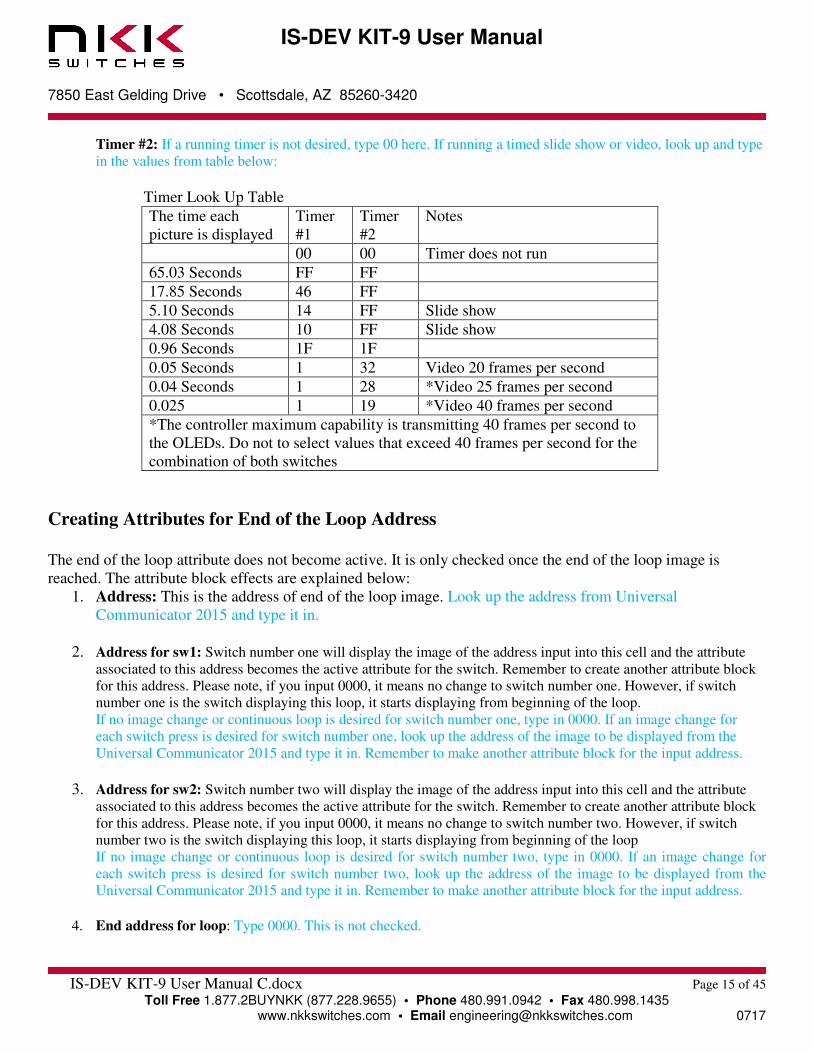
Timer #2: If a running timer is not desired, type 00 here. If running a timed slide show or video, look up and type
in the values from table below:
Timer Look Up Table
The time each
picture is displayed
Timer
#1
Timer
#2
Notes
00 00 Timer does not run
65.03 Seconds FF FF
17.85 Seconds 46 FF
5.10 Seconds 14 FF Slide show
4.08 Seconds 10 FF Slide show
0.96 Seconds 1F 1F
0.05 Seconds 1 32 Video 20 frames per second
0.04 Seconds 1 28 *Video 25 frames per second
0.025 1 19 *Video 40 frames per second
*The controller maximum capability is transmitting 40 frames per second to
the OLEDs. Do not to select values that exceed 40 frames per second for the
combination of both switches
Creating Attributes for End of the Loop Address
The end of the loop attribute does not become active. It is only checked once the end of the loop image is
reached. The attribute block effects are explained below:
1. Address: This is the address of end of the loop image. Look up the address from Universal
Communicator 2015 and type it in.
2. Address for sw1: Switch number one will display the image of the address input into this cell and the attribute
associated to this address becomes the active attribute for the switch. Remember to create another attribute block
for this address. Please note, if you input 0000, it means no change to switch number one. However, if switch
number one is the switch displaying this loop, it starts displaying from beginning of the loop. If no image change or continuous loop is desired for switch number one, type in 0000. If an image change for
each switch press is desired for switch number one, look up the address of the image to be displayed from the
Universal Communicator 2015 and type it in. Remember to make another attribute block for the input address.
3. Address for sw2: Switch number two will display the image of the address input into this cell and the attribute
associated to this address becomes the active attribute for the switch. Remember to create another attribute block
for this address. Please note, if you input 0000, it means no change to switch number two. However, if switch
number two is the switch displaying this loop, it starts displaying from beginning of the loop If no image change or continuous loop is desired for switch number two, type in 0000. If an image change for
each switch press is desired for switch number two, look up the address of the image to be displayed from the
Universal Communicator 2015 and type it in. Remember to make another attribute block for the input address.
4. End address for loop: Type 0000. This is not checked.

IS-DEV KIT-9 User Manual
7850 East Gelding Drive • Scottsdale, AZ 85260-3420
IS-DEV KIT-9 User Manual C.docx Page 16 of 45
Toll Free 1.877.2BUYNKK (877.228.9655) • Phone 480.991.0942 • Fax 480.998.1435 www.nkkswitches.com • Email [email protected] 0717
5. Timer#1: Type 00. This is not checked.
6. Timer#2: Type 00. This is not checked.
Downloading Attribute Table to the Dev Kit
After the attribute table is created, save the file. Then, open the Universal Communicator 2015 and click
“Download Excel”. Navigate and select the attribute file and click “Open”. After the download is finished, turn
the controller Off and On. Once restarted, the controller will work according to your program.
Example of How the Attributes Work
RAW DATA
CHARACTER
;
Setup
data
;2AH 56H 0000H 55H Flags
Start
Address
for
Switch
#1
Start
Address
for
Switch
#2 Reserve
* V 0000 55 00 0001 0003 0000
;
;
Attributes
data
;2AH 56H Address
Address
for sw1
Address
for sw2
End
address
for loop Timer#1 Timer#2
* V 0001 0003 0002 0000 00 00 ;
* V 0002 0001 0003 0000 00 00 ;
* V 0003 0000 0000 0010 10 FF
; beginning of
the loop
* V 0010 0000 0000 0000 00 00
; End of the
loop
If the above attribute file is downloaded to the controller, the controller will function as follows:

IS-DEV KIT-9 User Manual
7850 East Gelding Drive • Scottsdale, AZ 85260-3420
IS-DEV KIT-9 User Manual C.docx Page 17 of 45
Toll Free 1.877.2BUYNKK (877.228.9655) • Phone 480.991.0942 • Fax 480.998.1435 www.nkkswitches.com • Email [email protected] 0717
1. Upon power-up, switch number one displays the image at the address 0001. Switch number two displays
the image at the address 0003.
2. With no switch presses, the image on switch number one does not change. However, the image on
switch number two changes every 4.08 seconds to the next consecutive address until it reaches address
0010. Then, it starts again with address 0003 and keeps repeating.
3. When switch number two is pressed, the timer for the switch number two pauses as long as the switch is
kept pressed. This causes the image being displayed on switch number two to be displayed the amount
of the time that switch number two was kept pressed, plus 4.08 seconds (Timer #1 x Timer #2).
4. When switch number one is pressed, it causes switch number two to display the image at the address
0002 and switch number one to display image at the address 0003 (see the red box in the table above).
5. With no switch presses, the image on switch number two does not change. However, the image on
switch number one changes every 4.08 seconds to the next consecutive address until it reaches address
0010. Then, it starts again with address 0003 and keeps repeating.
6. If switch number one is pressed, the timer for the switch number one pauses as long as the switch is kept
pressed. This causes the image being displayed on switch number one to be displayed the amount of the
time that switch number one was kept pressed, plus 4.08 seconds (Timer #1 x Timer #2).
7. When switch number two is pressed, it causes switch number one to display the image at the address
0001 and switch number two to display the image at the address 0003. This is the same state described
in number 2 above.
IS-DEV KIT-9 User Manual
7850 East Gelding Drive • Scottsdale, AZ 85260-3420
IS-DEV KIT-9 User Manual C.docx Page 18 of 45
Toll Free 1.877.2BUYNKK (877.228.9655) • Phone 480.991.0942 • Fax 480.998.1435 www.nkkswitches.com • Email [email protected] 0717
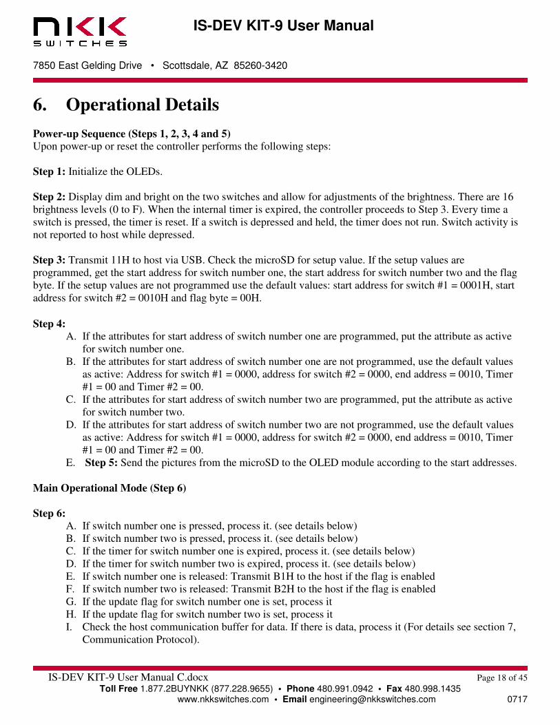
6. Operational Details
Power-up Sequence (Steps 1, 2, 3, 4 and 5) Upon power-up or reset the controller performs the following steps:
Step 1: Initialize the OLEDs.
Step 2: Display dim and bright on the two switches and allow for adjustments of the brightness. There are 16
brightness levels (0 to F). When the internal timer is expired, the controller proceeds to Step 3. Every time a
switch is pressed, the timer is reset. If a switch is depressed and held, the timer does not run. Switch activity is
not reported to host while depressed.
Step 3: Transmit 11H to host via USB. Check the microSD for setup value. If the setup values are
programmed, get the start address for switch number one, the start address for switch number two and the flag
byte. If the setup values are not programmed use the default values: start address for switch #1 = 0001H, start
address for switch #2 = 0010H and flag byte = 00H.
Step 4: A. If the attributes for start address of switch number one are programmed, put the attribute as active
for switch number one.
B. If the attributes for start address of switch number one are not programmed, use the default values
as active: Address for switch #1 = 0000, address for switch #2 = 0000, end address = 0010, Timer
#1 = 00 and Timer #2 = 00.
C. If the attributes for start address of switch number two are programmed, put the attribute as active
for switch number two.
D. If the attributes for start address of switch number two are not programmed, use the default values
as active: Address for switch #1 = 0000, address for switch #2 = 0000, end address = 0010, Timer
#1 = 00 and Timer #2 = 00.
E. Step 5: Send the pictures from the microSD to the OLED module according to the start addresses.
Main Operational Mode (Step 6)
Step 6: A. If switch number one is pressed, process it. (see details below)
B. If switch number two is pressed, process it. (see details below)
C. If the timer for switch number one is expired, process it. (see details below)
D. If the timer for switch number two is expired, process it. (see details below)
E. If switch number one is released: Transmit B1H to the host if the flag is enabled
F. If switch number two is released: Transmit B2H to the host if the flag is enabled
G. If the update flag for switch number one is set, process it
H. If the update flag for switch number two is set, process it
I. Check the host communication buffer for data. If there is data, process it (For details see section 7,
Communication Protocol).
IS-DEV KIT-9 User Manual
7850 East Gelding Drive • Scottsdale, AZ 85260-3420
IS-DEV KIT-9 User Manual C.docx Page 19 of 45
Toll Free 1.877.2BUYNKK (877.228.9655) • Phone 480.991.0942 • Fax 480.998.1435 www.nkkswitches.com • Email [email protected] 0717
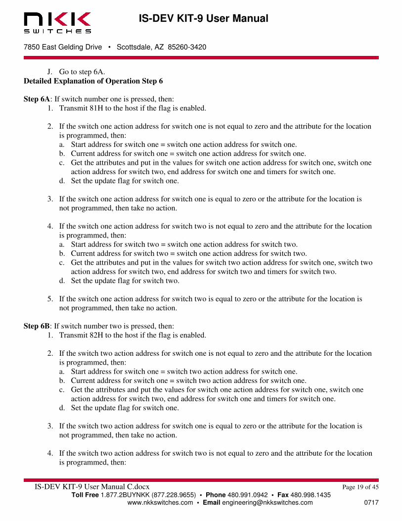
J. Go to step 6A.
Detailed Explanation of Operation Step 6
Step 6A: If switch number one is pressed, then:
1. Transmit 81H to the host if the flag is enabled.
2. If the switch one action address for switch one is not equal to zero and the attribute for the location
is programmed, then:
a. Start address for switch one = switch one action address for switch one.
b. Current address for switch one = switch one action address for switch one.
c. Get the attributes and put in the values for switch one action address for switch one, switch one
action address for switch two, end address for switch one and timers for switch one.
d. Set the update flag for switch one.
3. If the switch one action address for switch one is equal to zero or the attribute for the location is
not programmed, then take no action.
4. If the switch one action address for switch two is not equal to zero and the attribute for the location
is programmed, then:
a. Start address for switch two = switch one action address for switch two.
b. Current address for switch two = switch one action address for switch two.
c. Get the attributes and put in the values for switch two action address for switch one, switch two
action address for switch two, end address for switch two and timers for switch two.
d. Set the update flag for switch two.
5. If the switch one action address for switch two is equal to zero or the attribute for the location is
not programmed, then take no action.
Step 6B: If switch number two is pressed, then:
1. Transmit 82H to the host if the flag is enabled.
2. If the switch two action address for switch one is not equal to zero and the attribute for the location
is programmed, then:
a. Start address for switch one = switch two action address for switch one.
b. Current address for switch one = switch two action address for switch one.
c. Get the attributes and put the values for switch one action address for switch one, switch one
action address for switch two, end address for switch one and timers for switch one.
d. Set the update flag for switch one.
3. If the switch two action address for switch one is equal to zero or the attribute for the location is
not programmed, then take no action.
4. If the switch two action address for switch two is not equal to zero and the attribute for the location
is programmed, then:
IS-DEV KIT-9 User Manual
7850 East Gelding Drive • Scottsdale, AZ 85260-3420
IS-DEV KIT-9 User Manual C.docx Page 20 of 45
Toll Free 1.877.2BUYNKK (877.228.9655) • Phone 480.991.0942 • Fax 480.998.1435 www.nkkswitches.com • Email [email protected] 0717
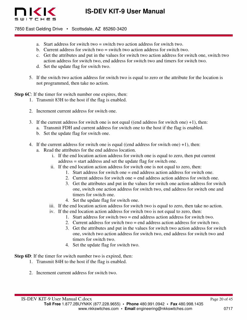
a. Start address for switch two = switch two action address for switch two.
b. Current address for switch two = switch two action address for switch two.
c. Get the attributes and put in the values for switch two action address for switch one, switch two
action address for switch two, end address for switch two and timers for switch two.
d. Set the update flag for switch two.
5. If the switch two action address for switch two is equal to zero or the attribute for the location is
not programmed, then take no action.
Step 6C: If the timer for switch number one expires, then:
1. Transmit 83H to the host if the flag is enabled.
2. Increment current address for switch one.
3. If the current address for switch one is not equal ((end address for switch one) +1), then:
a. Transmit FDH and current address for switch one to the host if the flag is enabled.
b. Set the update flag for switch one.
4. If the current address for switch one is equal ((end address for switch one) +1), then:
a. Read the attributes for the end address location.
i. If the end location action address for switch one is equal to zero, then put current
address = start address and set the update flag for switch one.
ii. If the end location action address for switch one is not equal to zero, then:
1. Start address for switch one = end address action address for switch one.
2. Current address for switch one = end address action address for switch one.
3. Get the attributes and put in the values for switch one action address for switch
one, switch one action address for switch two, end address for switch one and
timers for switch one.
4. Set the update flag for switch one.
iii. If the end location action address for switch two is equal to zero, then take no action.
iv. If the end location action address for switch two is not equal to zero, then:
1. Start address for switch two = end address action address for switch two.
2. Current address for switch two = end address action address for switch two.
3. Get the attributes and put in the values for switch two action address for switch
one, switch two action address for switch two, end address for switch two and
timers for switch two.
4. Set the update flag for switch two.
Step 6D: If the timer for switch number two is expired, then:
1. Transmit 84H to the host if the flag is enabled.
2. Increment current address for switch two.

IS-DEV KIT-9 User Manual
7850 East Gelding Drive • Scottsdale, AZ 85260-3420
IS-DEV KIT-9 User Manual C.docx Page 21 of 45
Toll Free 1.877.2BUYNKK (877.228.9655) • Phone 480.991.0942 • Fax 480.998.1435 www.nkkswitches.com • Email [email protected] 0717
3. If current address for switch two is not equal ((end address for switch two) +1), then:
a. Transmit FEH and current address for switch two to the host if the flag is enabled.
b. Set the update flag for switch two.
4. If the current address for switch two is equal ((end address for switch two) +1), then:
a. Read the attributes for end address location for switch two.
b. If the end location action address for switch two is equal to zero, then put current address for
switch two = start address for switch two and set the update flag for switch two.
c. If the end location action address for switch two is not equal to zero, then:
v. Start address for switch two = end address action address for switch two.
vi. Current address for switch two = end address action address for switch two.
vii. Get the attributes and put in the values for switch two action address for switch one,
switch two action address for switch two, end address for switch two and timers for
switch two.
viii. Set the update flag for switch two.
d. If the end location action address for switch one is equal to zero, then take no action.
e. If the end location action address for switch one is not equal to zero, then:
ix. Start address for switch one = end location action address for switch one.
x. Current address for switch one = end location action address for switch one.
xi. Get the attributes and put in the values for switch one action address for switch one,
switch one action address for switch two, end address for switch one and timers for
switch one.
xii. Set the update flag for switch one.
Step 6E: If switch number one is released: Transmit B1H to the host if the flag is enabled.
Step 6F: If switch number two is released: Transmit B2H to the host if the flag is enabled.
Step 6G: If the update flag for switch number one is set, then:
1. Clear the switch one update flag.
2. Transmit FDH and the current address for switch one to the host if the flag is enabled.
3. Send the picture from the microSD to the OLED module one according to the current address for
switch one.
Step 6H: If the update flag for switch number two is set, then:
1. Clear the switch two update flag.
2. Transmit FEH and current address for switch two to the host if the flag is enabled.
Send the picture from the microSD to the OLED module two according to current address for switch two.
Step 6I: Checks the host communication buffer for data. If there is data, process it (For details see section 7,
Communication Protocol).
Step 6J: Go to step 6A.
IS-DEV KIT-9 User Manual
7850 East Gelding Drive • Scottsdale, AZ 85260-3420
IS-DEV KIT-9 User Manual C.docx Page 22 of 45
Toll Free 1.877.2BUYNKK (877.228.9655) • Phone 480.991.0942 • Fax 480.998.1435 www.nkkswitches.com • Email [email protected] 0717
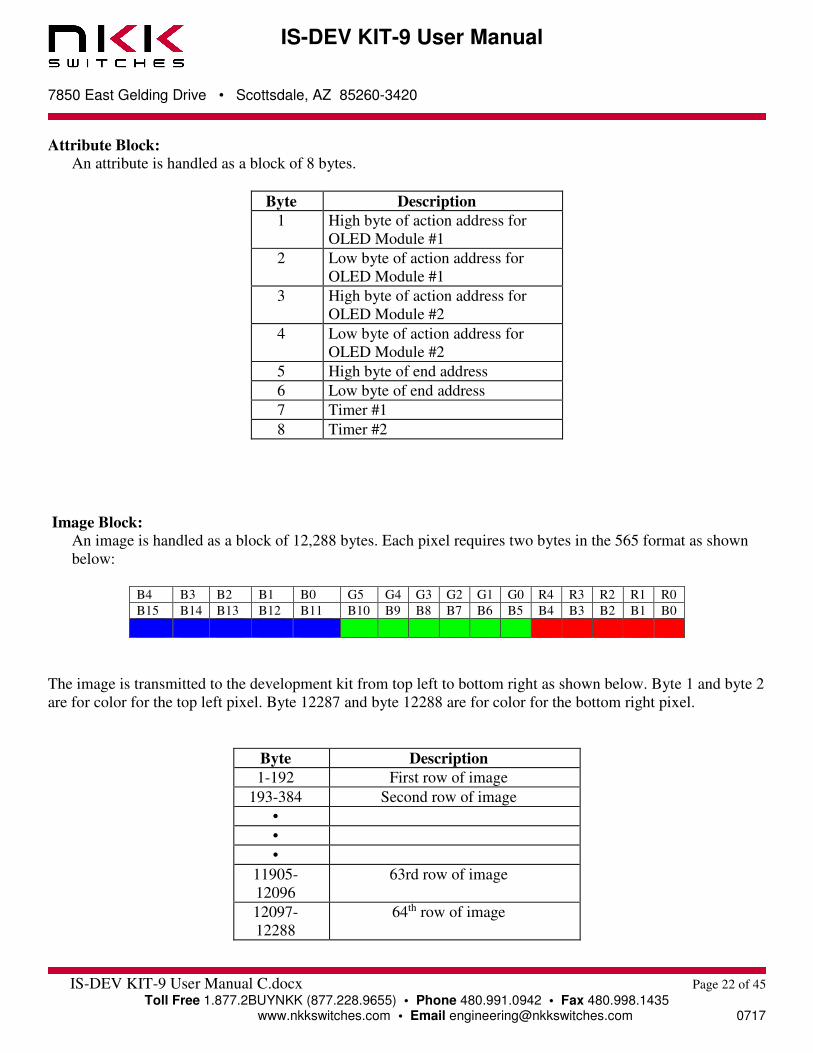
Attribute Block: An attribute is handled as a block of 8 bytes.
Byte Description
1 High byte of action address for
OLED Module #1
2 Low byte of action address for
OLED Module #1
3 High byte of action address for
OLED Module #2
4 Low byte of action address for
OLED Module #2
5 High byte of end address
6 Low byte of end address
7 Timer #1
8 Timer #2
Image Block: An image is handled as a block of 12,288 bytes. Each pixel requires two bytes in the 565 format as shown
below:
B4 B3 B2 B1 B0 G5 G4 G3 G2 G1 G0 R4 R3 R2 R1 R0
B15 B14 B13 B12 B11 B10 B9 B8 B7 B6 B5 B4 B3 B2 B1 B0
The image is transmitted to the development kit from top left to bottom right as shown below. Byte 1 and byte 2
are for color for the top left pixel. Byte 12287 and byte 12288 are for color for the bottom right pixel.
Byte Description
1-192 First row of image
193-384 Second row of image
•
•
•
11905-
12096
63rd row of image
12097-
12288
64th row of image
IS-DEV KIT-9 User Manual
7850 East Gelding Drive • Scottsdale, AZ 85260-3420
IS-Dev Kit-9 User Manual C.docx Page 23 of 45
Toll Free 1.877.2BUYNKK (877.228.9655) • Phone 480.991.0942 • Fax 480.998.1435 www.nkkswitches.com • Email [email protected] 0717
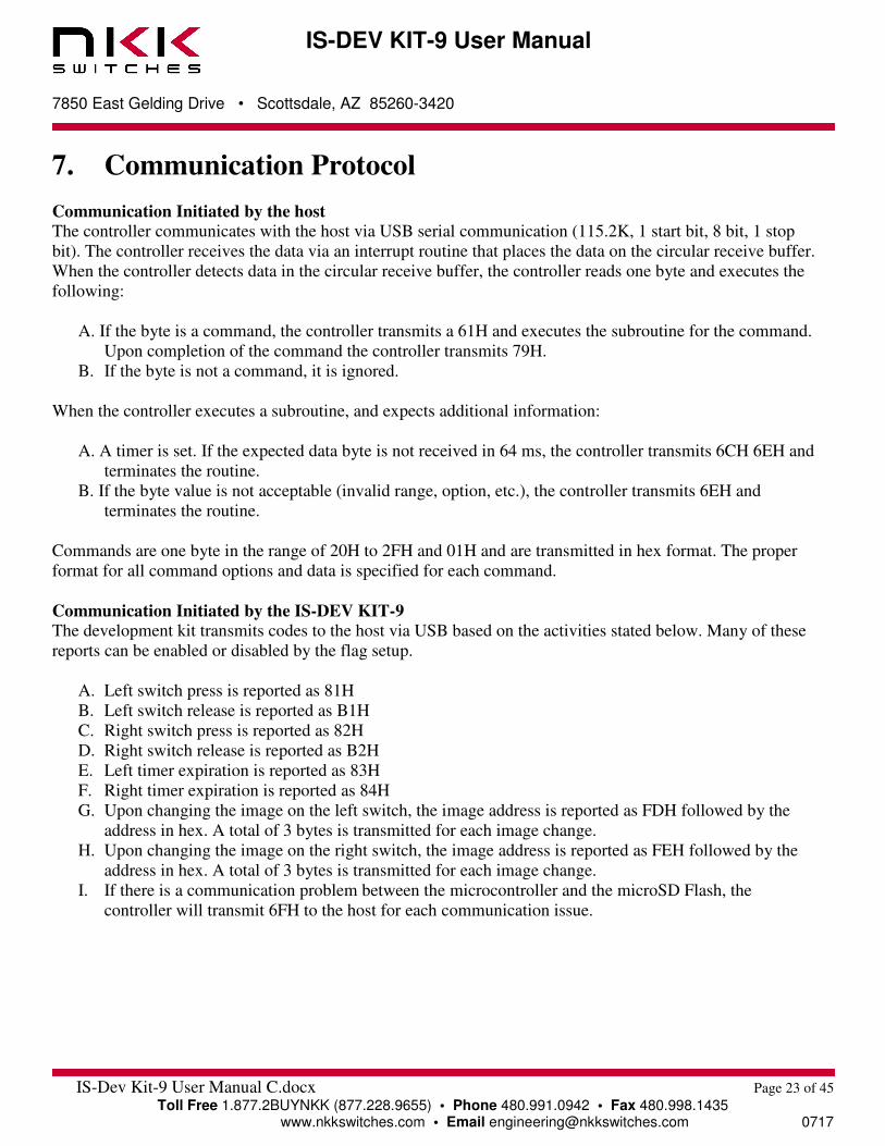
7. Communication Protocol
Communication Initiated by the host The controller communicates with the host via USB serial communication (115.2K, 1 start bit, 8 bit, 1 stop
bit). The controller receives the data via an interrupt routine that places the data on the circular receive buffer.
When the controller detects data in the circular receive buffer, the controller reads one byte and executes the
following:
A. If the byte is a command, the controller transmits a 61H and executes the subroutine for the command.
Upon completion of the command the controller transmits 79H.
B. If the byte is not a command, it is ignored.
When the controller executes a subroutine, and expects additional information:
A. A timer is set. If the expected data byte is not received in 64 ms, the controller transmits 6CH 6EH and
terminates the routine.
B. If the byte value is not acceptable (invalid range, option, etc.), the controller transmits 6EH and
terminates the routine.
Commands are one byte in the range of 20H to 2FH and 01H and are transmitted in hex format. The proper
format for all command options and data is specified for each command.
Communication Initiated by the IS-DEV KIT-9 The development kit transmits codes to the host via USB based on the activities stated below. Many of these
reports can be enabled or disabled by the flag setup.
A. Left switch press is reported as 81H
B. Left switch release is reported as B1H
C. Right switch press is reported as 82H
D. Right switch release is reported as B2H
E. Left timer expiration is reported as 83H
F. Right timer expiration is reported as 84H
G. Upon changing the image on the left switch, the image address is reported as FDH followed by the
address in hex. A total of 3 bytes is transmitted for each image change.
H. Upon changing the image on the right switch, the image address is reported as FEH followed by the
address in hex. A total of 3 bytes is transmitted for each image change.
I. If there is a communication problem between the microcontroller and the microSD Flash, the
controller will transmit 6FH to the host for each communication issue.
IS-DEV KIT-9 User Manual
7850 East Gelding Drive • Scottsdale, AZ 85260-3420
IS-Dev Kit-9 User Manual C.docx Page 24 of 45
Toll Free 1.877.2BUYNKK (877.228.9655) • Phone 480.991.0942 • Fax 480.998.1435 www.nkkswitches.com • Email [email protected] 0717
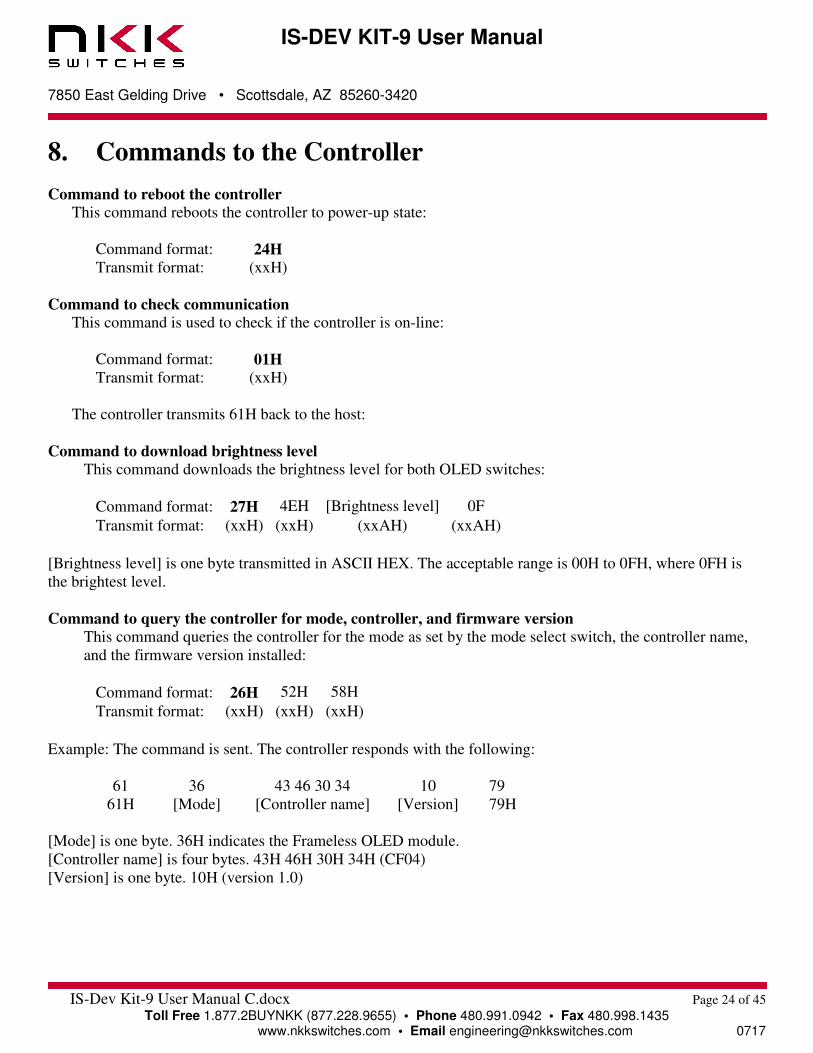
8. Commands to the Controller
Command to reboot the controller This command reboots the controller to power-up state:
Command format: 24H Transmit format: (xxH)
Command to check communication This command is used to check if the controller is on-line:
Command format: 01H Transmit format: (xxH)
The controller transmits 61H back to the host:
Command to download brightness level This command downloads the brightness level for both OLED switches:
Command format: 27H 4EH [Brightness level] 0F
Transmit format: (xxH) (xxH) (xxAH) (xxAH)
[Brightness level] is one byte transmitted in ASCII HEX. The acceptable range is 00H to 0FH, where 0FH is
the brightest level.
Command to query the controller for mode, controller, and firmware version This command queries the controller for the mode as set by the mode select switch, the controller name,
and the firmware version installed:
Command format: 26H 52H 58H
Transmit format: (xxH) (xxH) (xxH)
Example: The command is sent. The controller responds with the following:
61 36 43 46 30 34 10 79
61H [Mode] [Controller name] [Version] 79H
[Mode] is one byte. 36H indicates the Frameless OLED module.
[Controller name] is four bytes. 43H 46H 30H 34H (CF04)
[Version] is one byte. 10H (version 1.0)

IS-DEV KIT-9 User Manual
7850 East Gelding Drive • Scottsdale, AZ 85260-3420
IS-Dev Kit-9 User Manual C.docx Page 25 of 45
Toll Free 1.877.2BUYNKK (877.228.9655) • Phone 480.991.0942 • Fax 480.998.1435 www.nkkswitches.com • Email [email protected] 0717
Command to query the controller for firmware version This command queries the controller for the firmware version installed:
Command format: 26H 15H
Transmit format: (xxH) (xxH)
Example: The command is sent. The controller responds with the following:
61 11 79
61H [Version] 79H
[Version] is one byte. 11H (version 1.1)
Command for temporarily setting the timers This command sets both the left and right switch timers:
Command format: 26H 51H 55H [Left timer] [Right timer]
Transmit format: (xxH) (xxH) (xxH) (xxH) (xxH)
[Left timer] timer for left switch. Two bytes sent in hex format.
[Right timer] timer for right switch. Two bytes sent in hex format.
The command sets the timers with the given values and activates them. If either switch is pressed, or the
timers expire, the values are lost. These values are overwritten by the values stored on the microSD Flash in
the current address.
This command is useful for determining the best values for animations or movies.
Command to disable the timers and switch execution This command disables the timers and switch execution:
Command format: 26H 51H 5AH
Transmit format: (xxH) (xxH) (xxH)
The controller disables the timers and switch execution upon receiving this command. However, the switches
are still scanned and reported. They are enabled upon reboot, power-up or by a command from the host.
Command to enable the timers and switch execution This command enables the timers and switch execution:
Command format: 26H 51H 65H
Transmit format: (xxH) (xxH) (xxH)
The controller enables the timers and switch execution upon receiving this command.
IS-DEV KIT-9 User Manual
7850 East Gelding Drive • Scottsdale, AZ 85260-3420
IS-Dev Kit-9 User Manual C.docx Page 26 of 45
Toll Free 1.877.2BUYNKK (877.228.9655) • Phone 480.991.0942 • Fax 480.998.1435 www.nkkswitches.com • Email [email protected] 0717
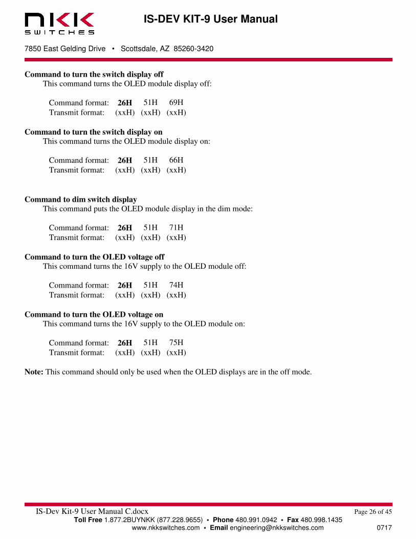
Command to turn the switch display off This command turns the OLED module display off:
Command format: 26H 51H 69H
Transmit format: (xxH) (xxH) (xxH)
Command to turn the switch display on This command turns the OLED module display on:
Command format: 26H 51H 66H
Transmit format: (xxH) (xxH) (xxH)
Command to dim switch display This command puts the OLED module display in the dim mode:
Command format: 26H 51H 71H
Transmit format: (xxH) (xxH) (xxH)
Command to turn the OLED voltage off This command turns the 16V supply to the OLED module off:
Command format: 26H 51H 74H
Transmit format: (xxH) (xxH) (xxH)
Command to turn the OLED voltage on This command turns the 16V supply to the OLED module on:
Command format: 26H 51H 75H
Transmit format: (xxH) (xxH) (xxH)
Note: This command should only be used when the OLED displays are in the off mode.
IS-DEV KIT-9 User Manual
7850 East Gelding Drive • Scottsdale, AZ 85260-3420
IS-Dev Kit-9 User Manual C.docx Page 27 of 45
Toll Free 1.877.2BUYNKK (877.228.9655) • Phone 480.991.0942 • Fax 480.998.1435 www.nkkswitches.com • Email [email protected] 0717
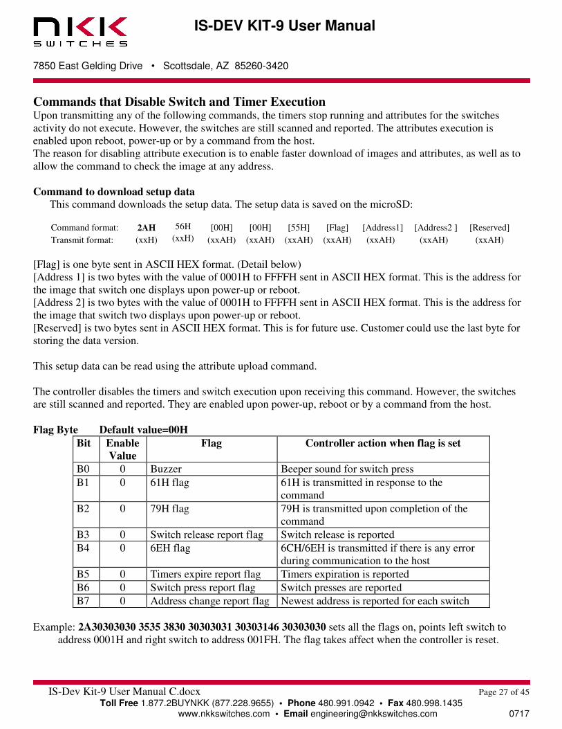
Commands that Disable Switch and Timer Execution Upon transmitting any of the following commands, the timers stop running and attributes for the switches
activity do not execute. However, the switches are still scanned and reported. The attributes execution is
enabled upon reboot, power-up or by a command from the host.
The reason for disabling attribute execution is to enable faster download of images and attributes, as well as to
allow the command to check the image at any address.
Command to download setup data This command downloads the setup data. The setup data is saved on the microSD:
Command format: 2AH 56H [00H] [00H] [55H] [Flag] [Address1] [Address2 ] [Reserved]
Transmit format: (xxH) (xxH) (xxAH) (xxAH) (xxAH) (xxAH) (xxAH) (xxAH) (xxAH)
[Flag] is one byte sent in ASCII HEX format. (Detail below)
[Address 1] is two bytes with the value of 0001H to FFFFH sent in ASCII HEX format. This is the address for
the image that switch one displays upon power-up or reboot.
[Address 2] is two bytes with the value of 0001H to FFFFH sent in ASCII HEX format. This is the address for
the image that switch two displays upon power-up or reboot.
[Reserved] is two bytes sent in ASCII HEX format. This is for future use. Customer could use the last byte for
storing the data version.
This setup data can be read using the attribute upload command.
The controller disables the timers and switch execution upon receiving this command. However, the switches
are still scanned and reported. They are enabled upon power-up, reboot or by a command from the host.
Flag Byte Default value=00H
Bit Enable
Value
Flag Controller action when flag is set
B0 0 Buzzer Beeper sound for switch press
B1 0 61H flag 61H is transmitted in response to the
command
B2 0 79H flag 79H is transmitted upon completion of the
command
B3 0 Switch release report flag Switch release is reported
B4 0 6EH flag 6CH/6EH is transmitted if there is any error
during communication to the host
B5 0 Timers expire report flag Timers expiration is reported
B6 0 Switch press report flag Switch presses are reported
B7 0 Address change report flag Newest address is reported for each switch
Example: 2A30303030 3535 3830 30303031 30303146 30303030 sets all the flags on, points left switch to
address 0001H and right switch to address 001FH. The flag takes affect when the controller is reset.
IS-DEV KIT-9 User Manual
7850 East Gelding Drive • Scottsdale, AZ 85260-3420
IS-Dev Kit-9 User Manual C.docx Page 28 of 45
Toll Free 1.877.2BUYNKK (877.228.9655) • Phone 480.991.0942 • Fax 480.998.1435 www.nkkswitches.com • Email [email protected] 0717
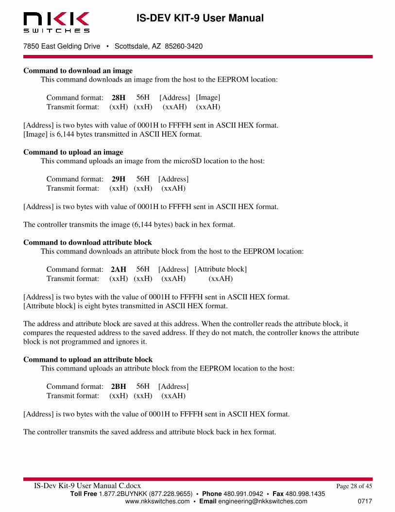
Command to download an image This command downloads an image from the host to the EEPROM location:
Command format: 28H 56H [Address] [Image]
Transmit format: (xxH) (xxH) (xxAH) (xxAH)
[Address] is two bytes with value of 0001H to FFFFH sent in ASCII HEX format.
[Image] is 6,144 bytes transmitted in ASCII HEX format.
Command to upload an image This command uploads an image from the microSD location to the host:
Command format: 29H 56H [Address]
Transmit format: (xxH) (xxH) (xxAH)
[Address] is two bytes with value of 0001H to FFFFH sent in ASCII HEX format.
The controller transmits the image (6,144 bytes) back in hex format.
Command to download attribute block This command downloads an attribute block from the host to the EEPROM location:
Command format: 2AH 56H [Address] [Attribute block]
Transmit format: (xxH) (xxH) (xxAH) (xxAH)
[Address] is two bytes with the value of 0001H to FFFFH sent in ASCII HEX format.
[Attribute block] is eight bytes transmitted in ASCII HEX format.
The address and attribute block are saved at this address. When the controller reads the attribute block, it
compares the requested address to the saved address. If they do not match, the controller knows the attribute
block is not programmed and ignores it.
Command to upload an attribute block This command uploads an attribute block from the EEPROM location to the host:
Command format: 2BH 56H [Address]
Transmit format: (xxH) (xxH) (xxAH)
[Address] is two bytes with the value of 0001H to FFFFH sent in ASCII HEX format.
The controller transmits the saved address and attribute block back in hex format.
IS-DEV KIT-9 User Manual
7850 East Gelding Drive • Scottsdale, AZ 85260-3420
IS-Dev Kit-9 User Manual C.docx Page 29 of 45
Toll Free 1.877.2BUYNKK (877.228.9655) • Phone 480.991.0942 • Fax 480.998.1435 www.nkkswitches.com • Email [email protected] 0717
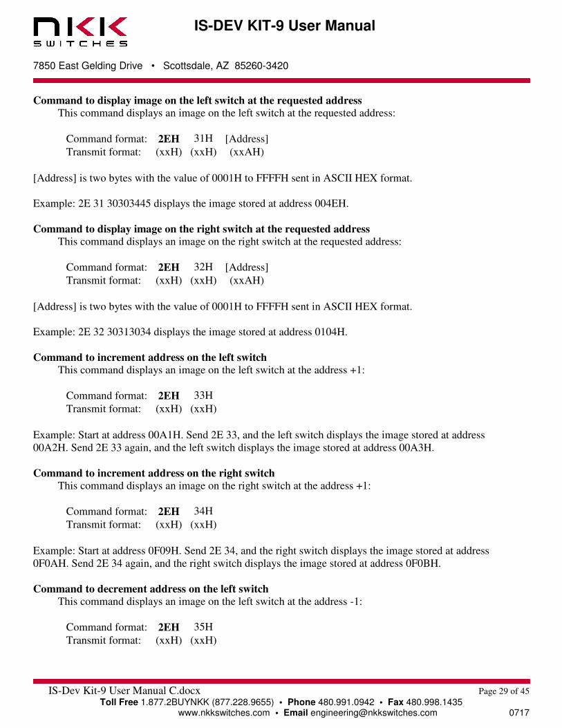
Command to display image on the left switch at the requested address This command displays an image on the left switch at the requested address:
Command format: 2EH 31H [Address]
Transmit format: (xxH) (xxH) (xxAH)
[Address] is two bytes with the value of 0001H to FFFFH sent in ASCII HEX format.
Example: 2E 31 30303445 displays the image stored at address 004EH.
Command to display image on the right switch at the requested address This command displays an image on the right switch at the requested address:
Command format: 2EH 32H [Address]
Transmit format: (xxH) (xxH) (xxAH)
[Address] is two bytes with the value of 0001H to FFFFH sent in ASCII HEX format.
Example: 2E 32 30313034 displays the image stored at address 0104H.
Command to increment address on the left switch This command displays an image on the left switch at the address +1:
Command format: 2EH 33H
Transmit format: (xxH) (xxH)
Example: Start at address 00A1H. Send 2E 33, and the left switch displays the image stored at address
00A2H. Send 2E 33 again, and the left switch displays the image stored at address 00A3H.
Command to increment address on the right switch This command displays an image on the right switch at the address +1:
Command format: 2EH 34H
Transmit format: (xxH) (xxH)
Example: Start at address 0F09H. Send 2E 34, and the right switch displays the image stored at address
0F0AH. Send 2E 34 again, and the right switch displays the image stored at address 0F0BH.
Command to decrement address on the left switch This command displays an image on the left switch at the address -1:
Command format: 2EH 35H
Transmit format: (xxH) (xxH)
IS-DEV KIT-9 User Manual
7850 East Gelding Drive • Scottsdale, AZ 85260-3420
IS-Dev Kit-9 User Manual C.docx Page 30 of 45
Toll Free 1.877.2BUYNKK (877.228.9655) • Phone 480.991.0942 • Fax 480.998.1435 www.nkkswitches.com • Email [email protected] 0717
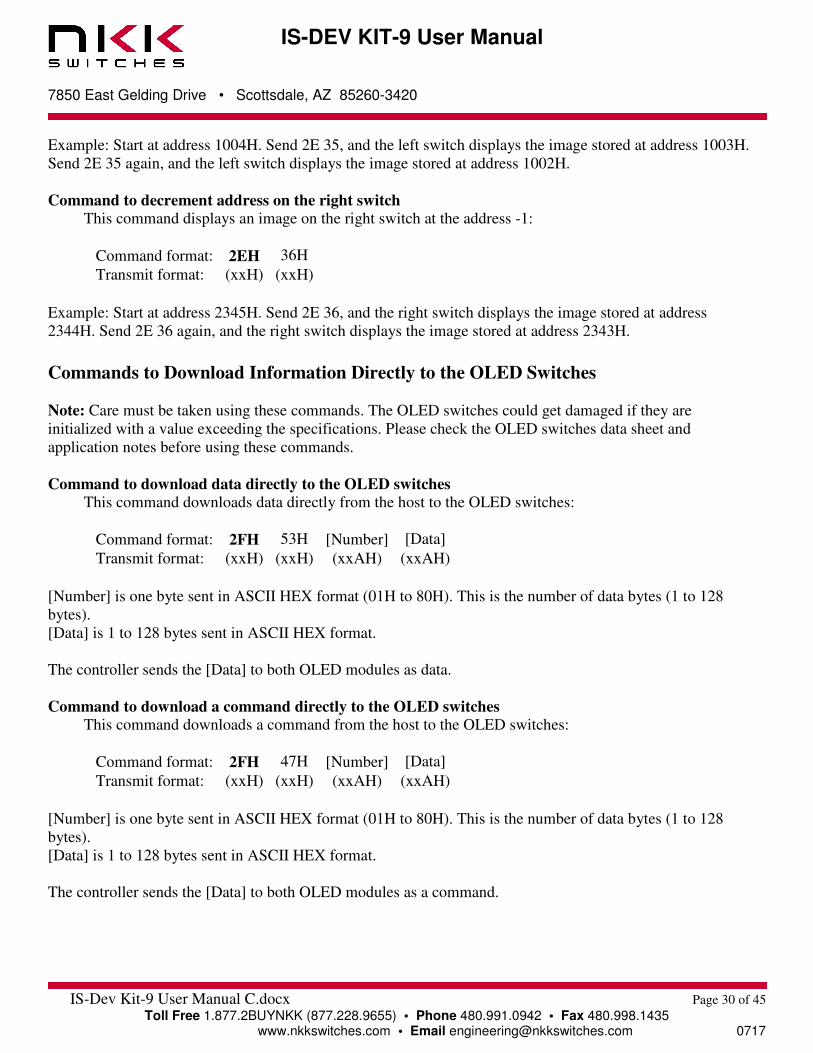
Example: Start at address 1004H. Send 2E 35, and the left switch displays the image stored at address 1003H.
Send 2E 35 again, and the left switch displays the image stored at address 1002H.
Command to decrement address on the right switch This command displays an image on the right switch at the address -1:
Command format: 2EH 36H
Transmit format: (xxH) (xxH)
Example: Start at address 2345H. Send 2E 36, and the right switch displays the image stored at address
2344H. Send 2E 36 again, and the right switch displays the image stored at address 2343H.
Commands to Download Information Directly to the OLED Switches Note: Care must be taken using these commands. The OLED switches could get damaged if they are
initialized with a value exceeding the specifications. Please check the OLED switches data sheet and
application notes before using these commands.
Command to download data directly to the OLED switches This command downloads data directly from the host to the OLED switches:
Command format: 2FH 53H [Number] [Data]
Transmit format: (xxH) (xxH) (xxAH) (xxAH)
[Number] is one byte sent in ASCII HEX format (01H to 80H). This is the number of data bytes (1 to 128
bytes).
[Data] is 1 to 128 bytes sent in ASCII HEX format.
The controller sends the [Data] to both OLED modules as data.
Command to download a command directly to the OLED switches This command downloads a command from the host to the OLED switches:
Command format: 2FH 47H [Number] [Data]
Transmit format: (xxH) (xxH) (xxAH) (xxAH)
[Number] is one byte sent in ASCII HEX format (01H to 80H). This is the number of data bytes (1 to 128
bytes).
[Data] is 1 to 128 bytes sent in ASCII HEX format.
The controller sends the [Data] to both OLED modules as a command.
IS-DEV KIT-9 User Manual
7850 East Gelding Drive • Scottsdale, AZ 85260-3420
IS-Dev Kit-9 User Manual C.docx Page 31 of 45
Toll Free 1.877.2BUYNKK (877.228.9655) • Phone 480.991.0942 • Fax 480.998.1435 www.nkkswitches.com • Email [email protected] 0717
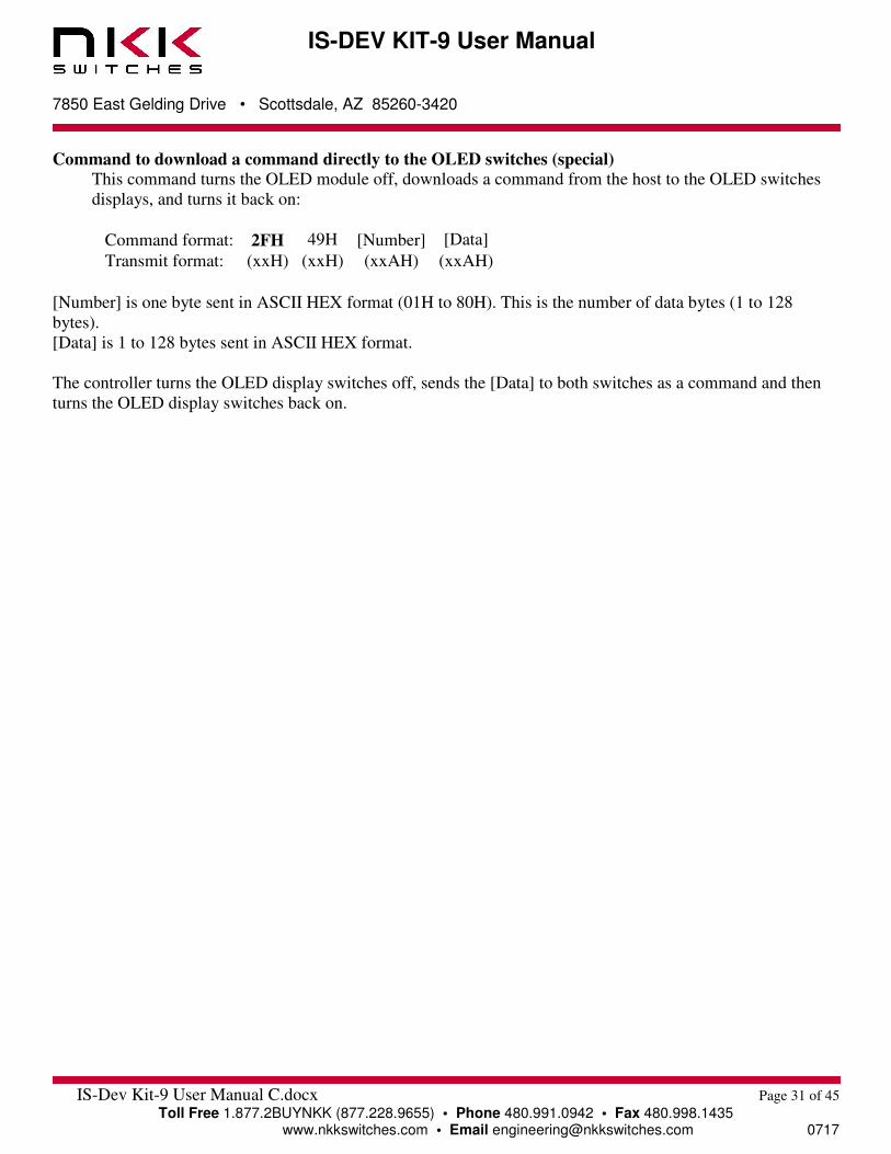
Command to download a command directly to the OLED switches (special) This command turns the OLED module off, downloads a command from the host to the OLED switches
displays, and turns it back on:
Command format: 2FH 49H [Number] [Data]
Transmit format: (xxH) (xxH) (xxAH) (xxAH)
[Number] is one byte sent in ASCII HEX format (01H to 80H). This is the number of data bytes (1 to 128
bytes).
[Data] is 1 to 128 bytes sent in ASCII HEX format.
The controller turns the OLED display switches off, sends the [Data] to both switches as a command and then
turns the OLED display switches back on.

IS-DEV KIT-9 User Manual
7850 East Gelding Drive • Scottsdale, AZ 85260-3420
IS-Dev Kit-9 User Manual C.docx Page 32 of 45
Toll Free 1.877.2BUYNKK (877.228.9655) • Phone 480.991.0942 • Fax 480.998.1435 www.nkkswitches.com • Email [email protected] 0717
9. Character Commands for the OLED Switches The following commands allow changing of the images being displayed. The host can download ASCII
characters to a specified location and the controller creates the image using a 7 x 10 font look up table based on
ON/OFF pixel colors. The host can download the ON pixel colors and Off pixel colors. These colors stay in
effect unless they are changed by the host.
The host can command the controller to change the status of one or more rows of pixels to a line color. The host
can download the line color. These colors stay in effect unless they are changed by the host.
The host can specify the brightness of the OLED switches.
None of these commands affect the storage memory.
Command to specify the OLED brightness (OLED color and OLED rocker switches) This command specifies the brightness for both OLED color and OLED rocker switches:
Command format: 27H 4EH [Brightness OLED color] [Brightness OLED rocker]
Transmit format: (xxH) (xxH) (xxAH) (xxAH)
[Brightness OLED color] is one byte sent in ASCII HEX format. The acceptable values are from 00H to 0FH,
where 0FH is the brightest. Default is 0FH.
[Brightness OLED rocker] is one byte sent in ASCII HEX format. The acceptable values are from 00H to 0FH,
where 0FH is the brightest. Default is 0FH.
The specified brightness levels go into effect immediately and remain in effect for the duration of the session.
Command to specify the color for line command (OLED Color) This command specifies the color used in line command:
Command format: 27H 47H [Color]
Transmit format: (xxH) (xxH) (xxAH)
[Color] is two bytes sent in ASCII HEX format. It specifies any of over 65,000 available colors. Default is
0000H.
The specified color remains in effect only for the duration of the session.
Command to specify the OFF/ON colors for Character generator commands (OLED Color) This command specifies the colors used in the character generator command.:
Command format: 27H 49H [Off color] [On color]
Transmit format: (xxH) (xxH) (xxAH) (xxAH)
[Off color] is two bytes sent in ASCII HEX format. It specifies any of over 65,000 available colors.
Default is 0000H. This is for the background color.
[On color] is two bytes sent in ASCII HEX format. It specifies any of over 65,000 available colors.
Default is FFFFH. This is for character color.
The specified colors remain in effect only for the duration of the session.

IS-DEV KIT-9 User Manual
7850 East Gelding Drive • Scottsdale, AZ 85260-3420
IS-Dev Kit-9 User Manual C.docx Page 33 of 45
Toll Free 1.877.2BUYNKK (877.228.9655) • Phone 480.991.0942 • Fax 480.998.1435 www.nkkswitches.com • Email [email protected] 0717
Command to generate characters for the OLED color #1 This command generates 1 to 12 characters (including the space between the characters) in font 8 x 10
from the specified coordinates in the OLED memory. Please note, the characters can be generated on the
memory outside the viewing area. The controller uses the specified ON/OFF colors:
Command format: 27H 51H [# of characters] [Row] [Column] [Characters]
Transmit format: (xxH) (xxH) (xxAH) (xxAH) (xxAH) [xxH]
[# of characters] is one byte sent in ASCII HEX format. The acceptable values are from 01H to 0CH.
[Row] is one byte sent in ASCII HEX format. It specifies the starting pixel row of the memory. The
acceptable values are from 00H to 36H.
[Column] is one byte sent in ASCII HEX format. It specifies the starting pixel column in the memory. The
acceptable values are from 00H to 58H.
[Characters] are 1 to 12 bytes of ASCII code. The acceptable values for characters are from 20H to 7FH.
0H 10H 16H 49H 4FH 5FH
0D 16D 22D 73D 79D 95D
0H/0D
23H/35D
2FH/47D
3FH/63D
Picture 1 OLED on-board memory map
Command to generate characters for the OLED color #2 This command generates 1 to 12 characters (including the space between the characters) in font 8 x 10
from the specified coordinates in the OLED memory. Please note, the characters can be generated on the
memory outside the viewing area. The controller uses the specified ON/OFF colors:
Command format: 27H 52H [# of characters] [Row] [Column] [Characters]
Transmit format: (xxH) (xxH) (xxAH) (xxAH) (xxAH) [xxH]
[# of characters] is one byte sent in ASCII HEX format. The acceptable values are from 01H to 0CH.

IS-DEV KIT-9 User Manual
7850 East Gelding Drive • Scottsdale, AZ 85260-3420
IS-Dev Kit-9 User Manual C.docx Page 34 of 45
Toll Free 1.877.2BUYNKK (877.228.9655) • Phone 480.991.0942 • Fax 480.998.1435 www.nkkswitches.com • Email [email protected] 0717
[Row] is one byte sent in ASCII HEX format. It specifies the starting pixel row of the memory. The
acceptable values are from 00H to 36H.
[Column] is one byte sent in ASCII HEX format. It specifies the starting pixel column in the memory. The
acceptable values are from 00H to 58H.
[Characters] are 1 to 12 bytes of ASCII code. The acceptable values for characters are from 20H to 7FH.
Command to change a line color (pixel row) for OLED color #1 This command changes the color of 1 to 64 rows of pixels from the specified row in the OLED memory.
Please note, the entire row of the memory changes, including the outside the viewing area. The controller
uses the specified line command color:
Command format: 27H 59H [# of rows] [Row]
Transmit format: (xxH) (xxH) (xxAH) (xxAH)
[# of Rows] is one byte sent in ASCII HEX format. The acceptable values are from 01H to 40H.
[Row] is one byte sent in ASCII HEX format. It specifies the starting pixel row of the memory. The
acceptable values are from 00H to 3FH.
Command to change a line color (pixel row) for OLED color #2 This command changes the color of 1 to 64 rows of pixels from the specified row in the OLED memory.
Please note, the entire row of the memory changes, including the outside the viewing area. The controller
uses the specified line command color:
Command format: 27H 5AH [# of rows] [Row]
Transmit format: (xxH) (xxH) (xxAH) (xxAH)
[# of Rows] is one byte sent in ASCII HEX format. The acceptable values are from 01H to 40H.
[Row] is one byte sent in ASCII HEX format. It specifies the starting pixel row of the memory. The
acceptable values are from 00H to 3FH.
IS-DEV KIT-9 User Manual
7850 East Gelding Drive • Scottsdale, AZ 85260-3420
IS-Dev Kit-9 User Manual C.docx Page 35 of 45
Toll Free 1.877.2BUYNKK (877.228.9655) • Phone 480.991.0942 • Fax 480.998.1435 www.nkkswitches.com • Email [email protected] 0717
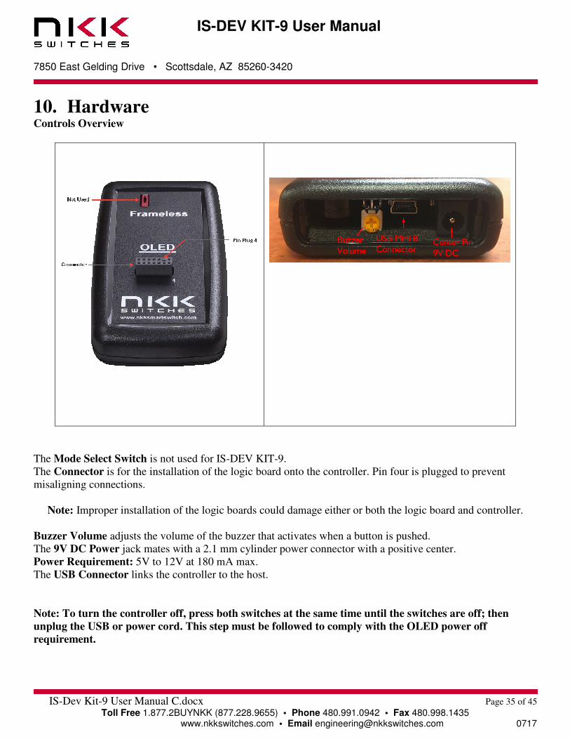
10. Hardware Controls Overview
The Mode Select Switch is not used for IS-DEV KIT-9.
The Connector is for the installation of the logic board onto the controller. Pin four is plugged to prevent
misaligning connections.
Note: Improper installation of the logic boards could damage either or both the logic board and controller.
Buzzer Volume adjusts the volume of the buzzer that activates when a button is pushed.
The 9V DC Power jack mates with a 2.1 mm cylinder power connector with a positive center.
Power Requirement: 5V to 12V at 180 mA max.
The USB Connector links the controller to the host.
Note: To turn the controller off, press both switches at the same time until the switches are off; then
unplug the USB or power cord. This step must be followed to comply with the OLED power off
requirement.
IS-DEV KIT-9 User Manual
7850 East Gelding Drive • Scottsdale, AZ 85260-3420
IS-Dev Kit-9 User Manual C.docx Page 36 of 45
Toll Free 1.877.2BUYNKK (877.228.9655) • Phone 480.991.0942 • Fax 480.998.1435 www.nkkswitches.com • Email [email protected] 0717
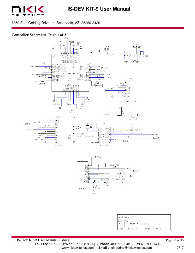
Controller Schematic, Page 1 of 2
IS-DEV KIT-9 User Manual
7850 East Gelding Drive • Scottsdale, AZ 85260-3420
IS-Dev Kit-9 User Manual C.docx Page 37 of 45
Toll Free 1.877.2BUYNKK (877.228.9655) • Phone 480.991.0942 • Fax 480.998.1435 www.nkkswitches.com • Email [email protected] 0717
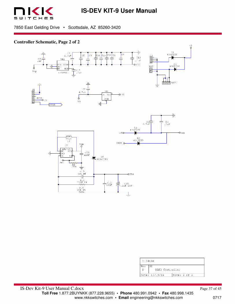
Controller Schematic, Page 2 of 2

IS-DEV KIT-9 User Manual
7850 East Gelding Drive • Scottsdale, AZ 85260-3420
IS-Dev Kit-9 User Manual C.docx Page 38 of 45
Toll Free 1.877.2BUYNKK (877.228.9655) • Phone 480.991.0942 • Fax 480.998.1435 www.nkkswitches.com • Email [email protected] 0717
Logic board, IS-L02L1, Two OLED SmartSwitches
12
C6
12
C5
V9
1IN
2
COM
3OUT
VR
ZSR330GTA
12
C1
12
C2
VDD
12
C3
12
C4
12
C8
LP
ss2
ss1Din1
CLK
1A
2B
7
8CLK
13QH
12QG
11QF
10QE
6QD
5QC
4QB
3QA
14
9CLR
U1
SN74HC164PWR
VDD
VDD
VDD2D1
3D2
4D3
5D4
6D5
7D6
8D7
10GND 11
CLK
13Q7
14Q6
15Q5
16Q4
17Q3
18Q2
19Q1
12Q8
20
9D8
1OC
U2
74HC574
1A2
K
DA1N41418Dout1
1A2
K
DB1N41418
SA
SB
1SW1
2SW2
3VDD
4ss
5RES
6D/C
7SCK
8SDI
10GND
9VCC
SWB
OLED
SB
SWbus
ss2VDD
RES
DC
SCK
Din
V16
1SW1
2SW2
3VDD
4ss
5RES
6D/C
7SCK
8SDI
10GND
9VCC
SWA
OLED
SWbus
SA
ss1
VDD
RES
DC
SCK
Din
V16
Din
oe
V16
12
C7
RES
SCK
V9
DC
Din1
Dout1
CLK
LP
SWbus
IDC14-L
5SCK6oe
8V16
4GND
7VCC
3DIN
2GND
1RES
9DC10
Pen11CLKss12
DATAss13LPss
14SWRD
J1
IDC14-L
SCKoe
V16
GND
VCC
DINGNDRES
DCPen
CLKssDATAss
LPssSWRD
J2
R2
25.5
R1
25.5
R4
25.5
R3
25.5

IS-DEV KIT-9 User Manual
7850 East Gelding Drive • Scottsdale, AZ 85260-3420
IS-Dev Kit-9 User Manual C.docx Page 39 of 45
Toll Free 1.877.2BUYNKK (877.228.9655) • Phone 480.991.0942 • Fax 480.998.1435 www.nkkswitches.com • Email [email protected] 0717
Enclosure size
Board photo
IS-DEV KIT-9 User Manual
7850 East Gelding Drive • Scottsdale, AZ 85260-3420
IS-Dev Kit-9 User Manual C.docx Page 40 of 45
Toll Free 1.877.2BUYNKK (877.228.9655) • Phone 480.991.0942 • Fax 480.998.1435 www.nkkswitches.com • Email [email protected] 0717
11. Key Terms & Definitions OLED Module NKK Switches’ OLED SmartSwitches and SmartDisplays.
Host Any computer, terminal, or other device that can communicate over the USB
line.
Controller A PCB assembly that controls one or more logic boards and the switches
associated with them. It communicates with a host over the USB line.
Logic Board A PCB assembly with “glue logic” for mounting switches. It is controlled by a
controller.
Byte An eight-bit hex value ranging from 00H to FFH (Decimal 0 to 255). The bit
format of a byte is: (B7 B6 B5 B4 B3 B2 B1 B0) where B7 is most significant
and bit B0 is least significant bit.
Nibble/Hex Digit A four-bit value ranging from 0H to FH. A byte consists of two nibbles.
ASCII A byte value representing a symbol.
Communication There are two formats to transmit a byte:
Format 1. Hex format - A hex byte is transmitted without any change to it. [xxH] will
be used to denote this.
All commands and some data are sent by using this format.
2. ASCII HEX format - Each nibble of the byte is converted to ASCII code
and sent as a byte. [xxAH] will be used to denote this.
For example, the hex byte 5AH is transmitted in two bytes, 35H and 41H.
The ASCII value for 5 is 35H and the ASCII value for A is 41H.
All addresses and most data are sent using this format.
Address A two-byte value ranging from 0001H to FFFFH representing the 65,536
memory locations for pictures and attributes on microSD Flash.
IS-DEV KIT-9 User Manual
7850 East Gelding Drive • Scottsdale, AZ 85260-3420
IS-Dev Kit-9 User Manual C.docx Page 41 of 45
Toll Free 1.877.2BUYNKK (877.228.9655) • Phone 480.991.0942 • Fax 480.998.1435 www.nkkswitches.com • Email [email protected] 0717
12. Firmware Issues
The problems found in the most current version are listed below and get resolved in the following version.

IS-DEV KIT-9 User Manual
7850 East Gelding Drive • Scottsdale, AZ 85260-3420
IS-Dev Kit-9 User Manual C.docx Page 42 of 45
Toll Free 1.877.2BUYNKK (877.228.9655) • Phone 480.991.0942 • Fax 480.998.1435 www.nkkswitches.com • Email [email protected] 0717
Appendix
Understanding Decimal, Hexadecimal and Binary Numbers
Decimal is the numbering system we use. It is called base-10. Every digit can be between 0 and 9.
The value of each digit is equal to the digit with ((Digit order) -1) zero in front.
Table 1, Base-10
Value in base-10
Digit x
10000 1000 100 10 1
Multiplication
for converting to
decimal
10(N-1) … … 104 103 102 101 100
Digit order Nth
digit
…. …. Fifth
digit
Fourth
digit
Third
digit
Second
digit
First
digit
Example: The value of each digit of the Base-10 number 7605 is as follow:
Fourth digit: 7 with (4-1) zero = 7000
Third digit: 6 with (3-1) zero = 600
Second digit: 0 with (2-1) zero = 0
First digit: 5 with (1-1) zero = 5
Numbering system A numbering system can be based on any number (Base-N). However, it must follow the rules:
1. Each digit must be between 0 and “Base minus one”. For example:
---Each digit for Base-2 numbering system can be 0 or 1
---Each digit for Base-5 numbering system can be 0 to 4
---Each digit for Base-8 numbering system can be 0 to 7
2. The value of each digit is equal to the digit with ((Digit order) -1) zeros in front.
All the operations that we use on base 10 numbering system (such as addition, subtraction, multiplication,
division) work the same for all the numbering systems. The difference is the carry over will be based on the
base-number of the numbering system instead of 10.
Why do we need other base numbering systems? Computers logic is based on two states:
Yes or No
False or True
High Voltage or Low Voltage
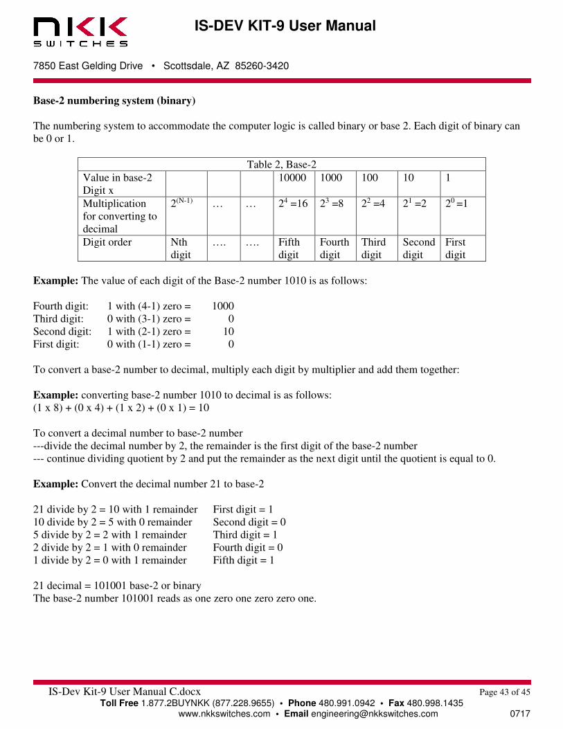
IS-DEV KIT-9 User Manual
7850 East Gelding Drive • Scottsdale, AZ 85260-3420
IS-Dev Kit-9 User Manual C.docx Page 43 of 45
Toll Free 1.877.2BUYNKK (877.228.9655) • Phone 480.991.0942 • Fax 480.998.1435 www.nkkswitches.com • Email [email protected] 0717
Base-2 numbering system (binary)
The numbering system to accommodate the computer logic is called binary or base 2. Each digit of binary can
be 0 or 1.
Table 2, Base-2
Value in base-2
Digit x
10000 1000 100 10 1
Multiplication
for converting to
decimal
2(N-1) … … 24 =16 23 =8 22 =4 21 =2 20 =1
Digit order Nth
digit
…. …. Fifth
digit
Fourth
digit
Third
digit
Second
digit
First
digit
Example: The value of each digit of the Base-2 number 1010 is as follows:
Fourth digit: 1 with (4-1) zero = 1000
Third digit: 0 with (3-1) zero = 0
Second digit: 1 with (2-1) zero = 10
First digit: 0 with (1-1) zero = 0
To convert a base-2 number to decimal, multiply each digit by multiplier and add them together:
Example: converting base-2 number 1010 to decimal is as follows:
(1 x 8) + (0 x 4) + (1 x 2) + (0 x 1) = 10
To convert a decimal number to base-2 number
---divide the decimal number by 2, the remainder is the first digit of the base-2 number
--- continue dividing quotient by 2 and put the remainder as the next digit until the quotient is equal to 0.
Example: Convert the decimal number 21 to base-2
21 divide by 2 = 10 with 1 remainder First digit = 1
10 divide by 2 = 5 with 0 remainder Second digit = 0
5 divide by 2 = 2 with 1 remainder Third digit = 1
2 divide by 2 = 1 with 0 remainder Fourth digit = 0
1 divide by 2 = 0 with 1 remainder Fifth digit = 1
21 decimal = 101001 base-2 or binary
The base-2 number 101001 reads as one zero one zero zero one.

IS-DEV KIT-9 User Manual
7850 East Gelding Drive • Scottsdale, AZ 85260-3420
IS-Dev Kit-9 User Manual C.docx Page 44 of 45
Toll Free 1.877.2BUYNKK (877.228.9655) • Phone 480.991.0942 • Fax 480.998.1435 www.nkkswitches.com • Email [email protected] 0717
Base-16 numbering system
Communicating base-2 numbers is difficult for humans because of all zeros and ones. To make it easier to
present computer data, a hexadecimal or base-16 numbering system is used. Four digits of base-2 numbering
system converts to one digit of base-16 numbering system. Since we did not have digits for 10, 11, 12, 13, 14
and 15, they were assigned letters A, B, C, D, E and F respectively.
Table 3, Number base conversion
Hexadecimal
base-16
Decimal
base-10
Binary base-2
0 0 0
1 1 1
2 2 10
3 3 11
4 4 100
5 5 101
6 6 110
7 7 111
8 8 1000
9 9 1001
A 10 1010
B 11 1011
C 12 1100
D 13 1101
E 14 1110
F 15 1111
10 16 10000
11 17 10001
etc etc etc
Table 4, Base-16
Value in base-16
Digit x
10000 1000 100 10 1
Multiplication
for converting to
decimal
16(N-1) … … 164
=65536
163
=4096
162
=256
161
=16
160 =1
Digit order Nth
digit
…. …. Fifth
digit
Fourth
digit
Third
digit
Second
digit
First
digit
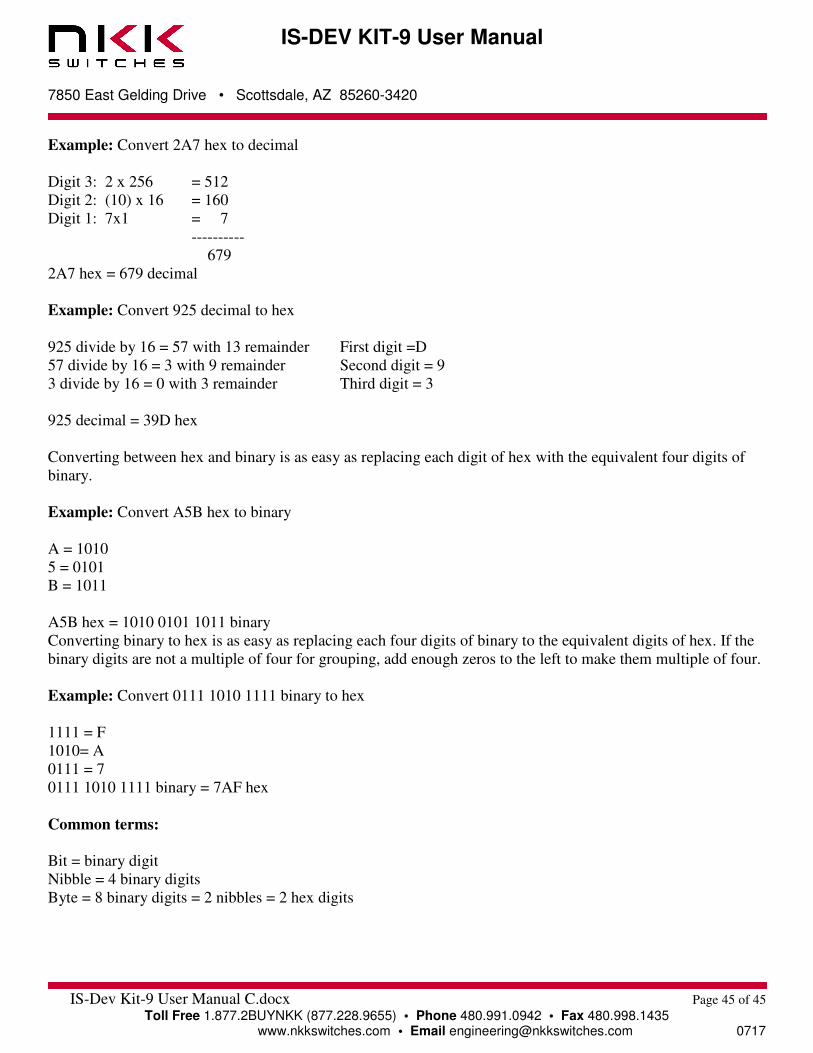
IS-DEV KIT-9 User Manual
7850 East Gelding Drive • Scottsdale, AZ 85260-3420
IS-Dev Kit-9 User Manual C.docx Page 45 of 45
Toll Free 1.877.2BUYNKK (877.228.9655) • Phone 480.991.0942 • Fax 480.998.1435 www.nkkswitches.com • Email [email protected] 0717
Example: Convert 2A7 hex to decimal
Digit 3: 2 x 256 = 512
Digit 2: (10) x 16 = 160
Digit 1: 7x1 = 7
----------
679
2A7 hex = 679 decimal
Example: Convert 925 decimal to hex
925 divide by 16 = 57 with 13 remainder First digit =D
57 divide by 16 = 3 with 9 remainder Second digit = 9
3 divide by 16 = 0 with 3 remainder Third digit = 3
925 decimal = 39D hex
Converting between hex and binary is as easy as replacing each digit of hex with the equivalent four digits of
binary.
Example: Convert A5B hex to binary
A = 1010
5 = 0101
B = 1011
A5B hex = 1010 0101 1011 binary
Converting binary to hex is as easy as replacing each four digits of binary to the equivalent digits of hex. If the
binary digits are not a multiple of four for grouping, add enough zeros to the left to make them multiple of four.
Example: Convert 0111 1010 1111 binary to hex
1111 = F
1010= A
0111 = 7
0111 1010 1111 binary = 7AF hex
Common terms:
Bit = binary digit
Nibble = 4 binary digits
Byte = 8 binary digits = 2 nibbles = 2 hex digits