IS 8638 (2006): Shipbuilding - Class A magnetic compasses ...
27
Disclosure to Promote the Right To Information Whereas the Parliament of India has set out to provide a practical regime of right to information for citizens to secure access to information under the control of public authorities, in order to promote transparency and accountability in the working of every public authority, and whereas the attached publication of the Bureau of Indian Standards is of particular interest to the public, particularly disadvantaged communities and those engaged in the pursuit of education and knowledge, the attached public safety standard is made available to promote the timely dissemination of this information in an accurate manner to the public. इंटरनेट मानक “!ान $ एक न’ भारत का +नम-ण” Satyanarayan Gangaram Pitroda “Invent a New India Using Knowledge” “प0रा1 को छोड न’ 5 तरफ” Jawaharlal Nehru “Step Out From the Old to the New” “जान1 का अ+धकार, जी1 का अ+धकार” Mazdoor Kisan Shakti Sangathan “The Right to Information, The Right to Live” “!ान एक ऐसा खजाना > जो कभी च0राया नहB जा सकता ह ै” Bhartṛhari—Nītiśatakam “Knowledge is such a treasure which cannot be stolen” IS 8638 (2006): Shipbuilding - Class A magnetic compasses, azimuth reading devices and binnacles - Tests and certifications [TED 19: Marine Engineering and Safety Aids]
Transcript of IS 8638 (2006): Shipbuilding - Class A magnetic compasses ...

Disclosure to Promote the Right To Information
Whereas the Parliament of India has set out to provide a practical regime of right to information for citizens to secure access to information under the control of public authorities, in order to promote transparency and accountability in the working of every public authority, and whereas the attached publication of the Bureau of Indian Standards is of particular interest to the public, particularly disadvantaged communities and those engaged in the pursuit of education and knowledge, the attached public safety standard is made available to promote the timely dissemination of this information in an accurate manner to the public.
इंटरनेट मानक
“!ान $ एक न' भारत का +नम-ण”Satyanarayan Gangaram Pitroda
“Invent a New India Using Knowledge”
“प0रा1 को छोड न' 5 तरफ”Jawaharlal Nehru
“Step Out From the Old to the New”
“जान1 का अ+धकार, जी1 का अ+धकार”Mazdoor Kisan Shakti Sangathan
“The Right to Information, The Right to Live”
“!ान एक ऐसा खजाना > जो कभी च0राया नहB जा सकता है”Bhartṛhari—Nītiśatakam
“Knowledge is such a treasure which cannot be stolen”
“Invent a New India Using Knowledge”
है”ह”ह
IS 8638 (2006): Shipbuilding - Class A magnetic compasses,azimuth reading devices and binnacles - Tests andcertifications [TED 19: Marine Engineering and Safety Aids]

IS 8638: 2006ISO 2269 : 1992
1/l'< rft (J I"fFICf)
~ - ~ ~ cfi~ cnHlfi,~~
\3QCf)x OI 3Tlx~ - WafOT 3Tlx ~JiIOI91
(~ Tfflerur )
Indian Standard
SHIPBUILDING - CLASS A MAGNETICCOMPASSES, AZIMUTH READING DEVICES
AND BINNACLES - TESTS ANDCERTIFICATION
( Second Revision)
ICS 47 .020.70
CBlS2006
BUREAU OF INDIAN STANDARDSMANAK SHAVAN. 9 BAHADUR SHAH ZAFAR MARG
NEW DELHI 110002
January 2006 Price Group 9
Marine Engineering and Safety Aids Sectional Committee, TED 19
NATIONAL FOREWORD
This Indian Standard (Second Revision) which is identical with ISO 2269 : 1992 'Shipbuilding - Class Amagnetic compasses, azimuth reading devices and binnacles - Tests and certification' issued by theInternational Organization for Standardization (ISO) was adopted by the Bureau of Indian Standards onthe recommendation of the Marine Engineering and Safety Aids Sectional Committee and approval ofthe Transport Engineering Division Council.
This standard was first published in 1977 and subsequently revised in 1989. The present revision wastaken up to harmonize it with the latest version of ISO Standard. In the present revision alt the threeparts of earlier standards have been amalgamated.
The text of the ISO Standard has been approved as suitable for publication as an Indian Standardwithout deviations. Certain conventions are, however, not identical to those used in Indian Standards.Attention is particularly drawn to the following:
a) Wherever the words 'International Standard' appear referring to this standard, they shouldbe read as 'Indian Standard'.
b) Comma (,) has been used as a decimal marker while in Indian Standards, the current practiceis to use a point (.) as the decimal marker.
In this adopted standard, reference appears to certain International Standards for which Indian Standardsalso exist. The corresponding Indian Standards which are to be substituted in their places are listedbelow along with their degree of equivalence for the editions indicated:
International Standard
1$0 449 : 1997 Ships and marinetechnology Magnetic,binnacles and azimuth readingdevices - Class A
ISO 1069 : 1973 Magneticcompasses and binnacles forsea navigation - Vocabulary
Corresponding Indian Standard
IS 4045 : 2005 Ships and marinetechnology - Magnetic compasses,binnacles and azimuth reading devicesClass A (second revision)
IS 5289 : 1989 Shipbuilding - Magneticcompasses and binnacles - Glossary ofterms (first revision)
Degree ofEquivalence
Identical
TechnicallyEquivalent
For BIS Certification Marking, details are given in National Annex A.
For the purpose of deciding whether a particular requirement of this standard is complied with, the finalvalue, observed or calculated expressing the resuhof a test or analysis, shall be rounded off in accordancewith IS 2 : 1960 'Rules for rounding off numerical values (revised)'. The number of significant placesretained in the rounded off value should be the same as that of the specified value in this standard.
IS 8638 : 2006ISO 2269 : 1992
Indian Standard
SHIPBUILDING - CLASS A MAGNETICCOMPASSES, AZIMUTH READING DEVICES
AND BINNACLES - TESTS ANDCERTIFICATION
( Second Revision)
Sedion 1: General
1.1 Scope 1.4 Test conditions
1.2 Normative references
1.3 DefinlOons
ISO 1069:1973, Magnetic compasses and binnaclesfor sea navigation - Vocabulary.
This International Standard specifies type-test andindi vi dual test methods, and gives the acceptablelimits of the characteristics necessary to guaranteeconform ity of magnetic compasses , azimuth readingdevices and binnacles to the general specificationsgiven in ISO 449.
Type-testing shall be carried out before the instruments covered come into regular service . For typetesting , new dev ices only w ill be accepted.
Ind iv idual testing shall be carried out before installat ion on-board ship; it is also desirable periodicallyand after repair. For individual testing , all devicesshall be in a clean and serviceable state when sub mitted for testing.
Unless otherwise stated. all tests shall be carriedout at a temperature of 20 °C ± 3 "C.
Devices which have passed the type-tests or the in dividual tests and comply with the requirementsshall be so certified in the language of the testauthority and in English .
Each type-test certificate is valid exclusively for themodel tested. In case of alterations or techn ical im provements which affect its compliance with ISO 449,the model shall be given a new identification number or ma rk and the type-test repeated . All alterations shall be submitted to the original testauthority who will decide whether a new type-lest isnecessary (see annexes A, Band C)
1.5 Certification
Magnetic compasses
The following standards contain provisions which ,through reference in this text, constitute provisionsof this International Standard . At the time of publication , the ed it ions indicated were val id . All stan dards are .subject to revision , and part ies toagreements based on this International Standardare encouraged to investigate the possibility of applying the most recent edit ions of the standards indicated below. Members of IEC and ISO ma intainregisters of currently valid International Standards.
ISO 449:1979, Shipbuildingand binnacles, class A.
For the purposes of this International Standard, thedefinitions given in ISO 1069 apply.
Unless otherwise stated, IJ is to be understood asthe horizontal component of the magnetic nux density, in microtesla (IlT) , at the place of examination .
Cop ies of the certificate shall be issued on demand .They shall explicitly be marked " copy " .
Acceptance of type-lest certificates and ind ividualtest cert ificates between countries w ill be a matterfor mutual agreement.
1
IS 8638 : 2006ISO 2269 : 1992
Section 2: Testing and cer1iflcation of class A compasses
2.1 General
2.1.1 Types of compass.s to be tested
Testing shall be carried out on all class A compasses. wIth or without a transmining system Allcompasses. other than those compasses withoutgimbals which are used as steering compassesonly. shall be tested w ith their gimbal rings andouter gimbal bearings.
2.1.2 Manufacturer's statement
The manufacturer shall produce a wntten statementcovering those requ irements which cannot beascertained during a type-test (see annex A) Thestatement shall incl ude the following po ints :
a) the coercivity and magnetic moment or the directional magnets.
b) that the paint inside the compass is of goodQuality and that over a period of two years it isnot likely to deteriorate to such an extent as tomake the compass unusable. either as a resultof the change of temperature over the range of- JO ·C to +- 60 · C or any other cause (for example the leg ibility of graduatIons shall not beImpaired by drscolouratlot, or blistering) :
C) under the conditions described in b). that thecompass liquid IS not likely to show any anpreCiable discolouratlon such as 10 render thecompass unusable.
d) whether toughened or non-toughened glass isused lor the top and bottom glass covers and itsthickness . alternatively. when a material otherthlln glass is used. that its strength Is equivalentto that or non-toughened glass of 4.5 mm thickness:
e) that the material of the compass card will notdistort:
n that the moment of inerti a of the directional sys tem is approximately the same about all horizontal axes passing Ihrough the bearing surfaceof the pivot jewel.
g) Ihe vertical distance between the m id-plane ofthe magnets of the d irectional system and theinner gimbal axis of the compass suppl ied .
h] the supporting fOfce on the p ivot at 20 °c.
2
i) that the inner and outer bearings of the gimbalrings are of the same type:
j) the length of bar magnels or diameter of ringmagnet form ing the directional system
In order to check that the manufacturer's statementabove has been fulfilled . sample checks may becarried out
2.1.3 Marking
2.1.3.1 Verily that
a) compasses are marked in a conspicuous placeon the compass card and the verge ring with thename of the manufaclurer. or other means ofident ification:
b) compass card and gimbal ring are marked w itha serial number:
c) the compass verge ring is marked With type andserial number
2.1.3.2 The markings given in 2 1 3 1 shall be notedon the certificate.
2.1.3.3 II other than alcohol. the type of liquid usedshall be ind icated on the bowl in the vi cinity of thefilling plug
2.2 Compa•• and gimballlng check. andt••t.
2.2.1 Construction and material
2.2.1.1 Condltton of compass bowl
The compass shall be inspected 10 see that it is undamaged and me chan ically perfect The liquid shallbe colourless and free from turbidity and formationof necks There shall be no leaks The pa int. including that on the compass card . shall be free fromcracks and blisters .
2.2.1.2 Non-m"Onetk: properties (type-test only)
Compass bowls and gimball ing shall be tested toverily their non -magnet ic properties (see 2.2.7.4).
2.2.1.3 Condltton .. hIgh temperature
The compass shall be warmed slowly from roomtemperature to 60 °C ± 2 °C and kept at least 8 h atthis temperature After this period . the compass
shall not show any mechanical damage . le akage orbubbl es Th e compa ss liqUid and pamt shall notshow any d eterioration . and the direct iona l systemshall not be deformed The compass shall operatesat isfactori ly
The d irectional system shall always be in contactw ith i ts pi vot
2.2.1.4 Condition at low temperature
The compass shall be slowly cooled to- 30 °C ± 2 "C and kept at least 8 h at thrs tem perature . After th is period the compass shall notshow any mechanical damage or deformation .leakage or bubbles . The liquid in the bowl shall notfreeze . d iscolour or separate into its ingred ie nts Aformat ion of flocks or ice shall not have occurredw ith in the liquid and the directional system shall notbe deformed . There shall be no deterioration in thefunction of the compass .
Th e directional system shall always be in contac tw ith its pivot .
2.2.1.5 Thickness of top and bottom glass covers(type-test only)
When made of non-toughened glass. the glass covers of compasses (i ncl ud in g compasses that haveno gimbals outs ide the bowl) shall have a thicknessof at least 4.5 mm .
When toughened glass IS us ed . the th ickn ess shallbe at least 3 mm.
When material other than glass is used. its properties shall be at least as strong as above [see2 1 2 d l]
The thickness of the glass may he ml'asurpd bymeans o f a m icrometer As tru s "'Quires the openingof the co m pas s. It sha ll be don e wh en the o therexam ina tions hav e been earned out
2.2.1.6 Transmitting system
A transmtll ing system shall not In te r fere Wit h re adIng the card or taking beanngs wllh an a71muthreading device
2.2.2 Compass gimballlng
2.2.2.1 Plane of gimbal ales (type-test only)
The g imbal axes shall tie in one plane . With in a tot erance of 1 mm .
Th is test may be carr ied out fro m a fi xed horizontalreference plane by means of a su itable scale
IS 8638 : 2006ISO 2269 : 1992
2.2.2.2 Angle 01 gimbal ues and Int....ectlon ofyertic.1 planes puslng through them (t\ pp ·test on ly l
The angle iormeo by Ih~ o ute r ilnel Inner gimbalav es sh all toe 90" • l ' Thl' ve ru c a t pla nl's thr ouyhth e g imba l axes shall Intt'l s<,ct 10 \N,l/ltn 1 min 01 thePivot po int An y end p la y shall not cause thef>(' toterances 10 be exceeneo
Th e o ut er g imbal aXIs sh all be on the lor e and andirecti on
Measurl'men t of thp a."" angl ps ma y bl' made 01'm eans 01 thl' test stand graduation wh en IIrs t o nethen the oth er gimbal aMI S IS brought Into the vert ica l plano 01 view paSSin" thro ugh the graduat ionce nlre by tu rrunq the comnass su pport
Detl'rminat lon 01 the int ers ec tion li ne ma y bE' r ar ried out on a lpst stand by rn easurmq the ol sp l :Jce.m ent o f thl' rorn na ss su p nort in a d irect ionperpennrcu iar to l.'.ther 01 th e gimbal axes .
2.2.2.3 F..-dom 0' moyement within gimbal ring
When th l.' " Imbal r rnq IS In the ho n zonta: planl' th ..co m pas s bowi sha ll Ir ee ly re volve ab out Ihe Inne raxis up 10 .~ 40"
The measurement ma y be ea rn ed out by aclinometer pl.1cE'd on thl' top g lass r-over or I/prgerino
2.2.2.4 Horlzont.' position
Thl' compass bowl shall be balanced so that 11'I!(' rge nng or lop Qlass COV N settl es 111 Ih .. nor»l o nta l p lan" to Within r whp.n thl' g imbal n nll ISfj)(ed In a nonzontal po sinon Th,s sha ll be sowheth"r the az irn uth ,p actln" de VIce or o l hl't at ta rhment or maQnlfl" r 's rn nosuron o r not
M pasu rem"n t shall be ran Ipd out by plau ng a sp lntleve l 01 s illtahl" sen " ltlvlly o n the lop gla ss o r usverge ring
2.2.2.5 Friction of Inn., gimbal a.i.
When Ihe gimbal r inQ IS k"rt in the ho nzonta l co s'lion a nd Ihe com p ass bowl IS inc li ne d by ~_ sr. Itsh all ret u rn 10 Wllh ln 7" 01 th" honlo nl a l p lane
The tes t m ay be carn"d out by me an s of aclinometer o r sp ir ll le ve l
2.2.2.8 In,...- and ovt.r gimbal bearings (ty pe· l estonly)
Th" be 'l rt ngs of t h" Inner and oute r gimba l a vesshall be o t tbe same ty p..
3
IS 8638 : 2006ISO 2269 : 1992
2.2.3 Compass bowl
2.2.3.1 R..-tve bearfng ring graduation (if any)
If the standard compass is provided with a scale forthe measurement of bearings relative to the ship 'shead . the scale shall be graduated in 3600 clockwise . zero. as seen through the azimuth readingdevice, indicating the direction of the ship 's head,
This graduation shall be checked.
2.2.3.2 Error due to eecentrtclty of bearing ringgraduMton
If there is a relative bearing ring. the perpendicularto the plane of this ring. through the graduationcentre. shall be within 0.5 mm of the pivot point.
This may be tested when the compass bowl is dismantled by centring the pivot on the test stand. rotating the compass bowl and observing theeccentricity of the relative bearing ring through thetest stand telescope.
Anernatively. examination may be carried out onassembled compasses by measuring the graduationdiameter and reading the directional error in the teststand , The maximum permissible direction error isgiven in table 1 as a function of the graduation diameter.
~Ioft""".mm....Imum pennlellbMt
dIBclloft error, •
115 0.5142 0.4190 0.3280 0.2
22.3.3 AccunIq of Wi....... of utmuetl rMdtng... (type-Ie<;l only)
The distance between the rotating axis of theazimuth reading dev ice (bridge type or ring type)and the vertical rotation axis of the com pan card,passmg through the pivot point . shalt not exceed0.5 mm
Depending on the construction of the azimuth reading device. the rotation aICls may be defined eitherby an indentation or centre boss on the top glasscover of the compass. or by the centre of the insideor outside of the verge ring. or by the compass bowloutSIde rim .
The examination may be carried out by measuring.on a compass test stand. the displacement wh ich is
necessary to bring the compass pivot point. whenhorizontal . and the rotation axis of the azimuthreading device. one arter the other into coincidencewith the rotation axis of the test stand.
2.2.4 Compass card bearing
2.2.4.1 Height of pivot bearing (type-test only)
The pivot point shall not deviate from the horizontalplane through the inner gimbal axis by more than1 mm. Should the pivot bearing be equipped with avertical spring suspension . Ih is condition shall befulfilled when Ihe directional system is completelyimmersed.
When the compass bowl is opened. this examinationmay be carried out by using a depth gauge. thecompass rim being the reference plane.
2.2.4.2 Protection of directional system againstdisplacement
The directional system mounting in the compassbowl shall be constructed in such a way that it returns to the original position on its pivot when thebowl is inverted and then returned to its normalposition .
This can be checked by inspection.
2.2.4.3 Freedom of tilt of directional system
The directional system and the compass bowl shallbe constructed in such a way that the directionalsystem can rotate freely when the compass bowl istilted in any direction at an angle of
al 10° when the compass bowl has an externalgimbal system;
b) JOO in other cases
The examination may be carried out by means of arevolving platform with adjustable inclination.
2.2.5 Lubber m8rka
2.2.5.1 Number of lUbber marts
Each compass shall be filted with a lubber mark indicating the direction of the ship's head (main lubbermark) . This main lubber mark shall be clearly identifiable and be within 0.50 of the fore and an g imbalaxis .
Other lubber marks are allowed. showing the direction of the ship 's stern and thwartship respectively.These lubber marks shall fulfil the conditions laiddown in 2 252 to 225 4
2.2.5 .2 VIsibility of lubber mart(s)
The ma in lubber mark shall be of such design thatthe card may be read from the steering positionagainst the lubber mark when the compass bowl istilted as in 2.2.4.3. In the case or a gimballed cornpass . the use of a plate lubber line is permitted (seealso 2.26.1.2).
The examination may be carried out by visual inspection in conjunction with the examination in2.24.3.
2.2.5.3 Width of lubber mart(s)
The width of the lubber mark(s) shall not subtend anangle greater than 0.50 of the card graduation.
The examination may be carried out by visual inspection .
2.2.5.4 Distance between lubber mart(s) and cardouter edge
The distance between the lubber mark(s) and thecard outer edge shall be between 1.5 mm and3 mm except in the case of projector compasses .when the tolerance shall be between 0.5 mm and1.5 mm.
The examination may be carried out by us ing amirror gauge which is laid on top or the bowl r im .or by travelling microscope. or by direct measurement when the compass is dismantled .
In the case or hemispherical compasses. th is becomes a type-test only and can be ascerta ined whenthe compass is dismantled.
2.2.6 Directional system
2.2.8.1 Compass card
2.2.8.1.1 Graduation
The card shall be graduated in 360 single degreesstarting from north clockwise as viewed from aboveThe cardinal points shall be indicated by the capitalletters N. S . E and W; the intermediate points m~y
also be marked . Alternatively. the north point maybe ind icated by a suitable symbol The card shall benumbered every 10".
IS 8638 : 2006ISO 2269 : 1992
Where the compass card IS pnnteo on bOth Sides.the graduations shall coincide With a tolerance of0.2"
The examination shall be carried out Visua lly
2.2.11.1.2 Re.cs.bliity
In steering compasses . the hne thickness lind theheight or the figures and letters shall allow a personwith normal vision to read the card Ooth In daylightand in artificial light at a distance ot 1.4 m
For reflecting and project ing compasses the mainlubber mark and at least 15" of thf' ca rd on elthf'rside shall be readable by a person With normal VI·sian at a distance or 1 m from the periscope lube
The use or a magnifying device IS pE>rmll1t>d
The examination shall be carried out Visually
2.2.11.1.3 ReIdoMtllp of edge of compass card andptvot bearing (type-test only)
When the verge ring and the seating lor the aZlmulhreading device lire both bonzonta t. the card graduated edge. the lubber mark it a POint. the pivot POintand the outer g imbal aXIs 5hall all Ite Within 1 mmof the horlzonlal plane pas~llng through the gimbalaxis fixed to Ihe compass bowt ThiS measurementcan only be made when lhe compass bowl IIopened It can be made us ing a deplh gaugfl trom afixed reference plane .
2.2.1.2 Directional system magnets
2.2.1.2.1 Magnetic moment
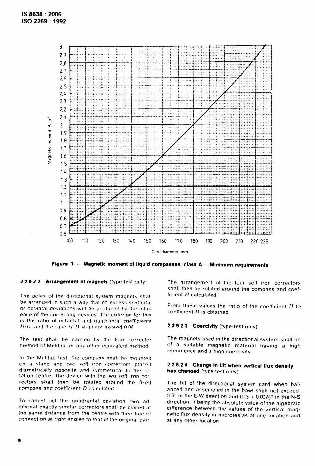
The magnetic moment 01 Ihe chrerllonal systemshall . depending on thp e<tld diameter ~e not '-11.than the values given in figure 1
Te,ting mAy be CArr ied out by means of A
magnetometer l denect ion method) or anv ofhl.'r ao propriate means
5
IS 8638 : 2006ISO 2269 : 1992
3
2.9
2.82.72.6
2.':>2.4
2.3
2.221
-« 2
~1.9
~ 1.8O!. 1"7;; '.'c 1.6'".s 1.5
1.4U1.2i :.'1
0.90.80 7
ro 120 130 11.0 15C 160 170 lBO 190 200 210 220 225
Fioure 1 - Magnetic moment 0' liquid compasses, class A - Minimum requirements
2.2.8.2.2 Arrangement 0' magnets (lype - te~t only)
The p01.>~ o f Ih .. d tr,' cl lonal sy stem maqnets shallhI' '1rr '1n(jPrt H1 ~ lIch ;1 W;jY thil l no " XCI'SS ~ " x l a nl ;j l
or oc! '!nla ; d '~ ',"l il l l o n s w ill he producert Oy the rnflu ence of the correr nnq de v ice s Th!! cnterlon for thisIS the r.ll.o of ocl.jnt;j l and qu .,c!ran lal coeffi cientsII /> ilnd tn" r .l l ,i) l l /l st!l ll no t " "(",'('(1 nnR
The lest sh-tll be camed by th " four co r re c to rmethod of M .~ ld illJ . O f ,l ny o ther pq lJtva len l me th od
In th O' M t' Ir1 il ll It's t. th e r ornn -rss ~h a l! h O' m o untr-don .1 <, t,lnct ;Jnd two soil ' ro n f () rr er:o r ~ plan~ct
nlametrl ca lly onoosu« ann symmetri cal to the rotallo n ce nlre Thl' devrce With the tw o sort Iro n cor rec tors sha l l thp n be ro lated around the fixedcompass an d c(){'ffic'ent l) c;; lcul'1ted
To cancel o ut Ih£' q uadrant at de v iation . two ad dlttonal exactly s.rn rtar correc to rs sha ll he pl '1ced <I Ith !' same d.stance from the cenl re w fl h their hnf> o fconnec tio n at "oht anq les to tha t o f I he o r iq m a: pa ir
Th f> arranqernent of th e four soft Iron corre ctorsshall then be ro la led aroun d the compass and coer fiCien t 1/ calcula ted
From thes!' values the ra u o of the co e rtic if>n t " tocoelTic ient /) IS obtained
2.2.6.2.3 Coercivlty (type-test on ly)
Thp. magnel s used in Ih e direct io na l syste m shall heof a suitable ma gnelic m ater ial hav ing a h ig hremanence and a hig h coe r c.vi tv
2.2.6.2_4 Change In t1« When vertical flux densityhas c:hanged (ty pe-te st o nly)
The li lt of th e direct ional system ca r d wh en bal anced and assem bled in Ihe bo wl shall no t exceed0.5' in Ih l' E-W d"ection and (0.5 + 0.03,~r in the N-Sd irect io n. ~ being th e absolu te value of t he alqebraicdi fferen ce bet w een the values o f the ve rt ical m agnetrc nux densrty In m .crotesias at one tocanon a ndat any o ther tocatron
The test shall be carried out with Iiqu id -lilled com passes of the conventional type when the bowl isdismantled or by means of a su itable optical devicewhen closed . In the case of other compasses. thetest may be carried out when the bowl is dismantled
2.2.6.3 Period
There are two tests, test A for periodic compassesor test B for heavily damped or aperiodic compasses. If the compass passes the appropriate test.it satisfies the requ irements.
2.2.6.3.1 Test A (periodic compasses)
The card is deflected 40° from the magneticmeridian and held there for at least 10 s. It is thenreleased and the time taken between the first andsecond passing of the orig inal head ing is noted. Thistime. in seconds. shall not be less than
)2600/I
This is repeated on the other side of the merid ianand the mean is taken .
2.2.6.3.2 Test 8 (heavily damped or aperiodiccompasses)
The card is deflected 90°. held there for at least10 s and then released . The time. in seconds. takento return finally to within 1° of the magnetic meridianshall not be more than
) 57600/I
This is repeated on the other side of the meridianand the mean is taken .
2.2.7 Accuracy
2.2.7.1 DlrectJonal error
The directional error is a direction <II systemconstructional error. It is composed of
a) error of magnet orientat ion with regard to thegraduat ion of the card (collimation error).
b) inaccuracies of the compass card graduation .
c) eccentricity of the compass card graduat ion withregard to the rotation centre of the card .
The directional error shall on no heading exceed0 ,5°.
The examination may be carried out on a compasstest stand. After having brought the rotation centreof the compass card into the rotation axis of the teststand. the directional error can be read at the C<lrd
IS 8638 ; 2006ISO 2269 ; 1992
graduallon by me ans 01 a tete-scope o r any otherappropriate means . when the vel1lCal plane at thesight passing through the rota lion 8)( 15 has beenal igned with the m:lgnetic mendian in advance Thi Smeasurement sh:lll be carried out on at teast fourequidistant headings When measurmg , the topglass shall be tapped gently to enmmate the errordue to tricnon (see 2 2 7 3)
In transmlllmg compass es the dir..cllonal .. rror ap ·plies to the compass Without nU)(glllte The nU)(Qllteof a transmining compass shall be pllllced so that theinfluence on the card he:ld lng snau not excet'd 0.5'on any he:ld ing
NOTE1 II the lest i ll vndfftal<en ,1'1 the compa.. bowlit should be noted that the resultIng value t~ ,ncludeithe dev iation due 10 :lny mitgnt'hC maler lal In the compus and/or in the nvxgale.
2.2.7.2 Error of lubber mart.
Lubber error is a con structional error of the corn pass bowl and gimbal . which dept'nds on the rela·tive pos ition of tht' m:lln lubber ma", (II it I. fixed ).the pivot beannq . and lhe direction of the outergimbal ax is
For compasses w llh a movable lubber mark. butwith an aUXIliary graduation for coefficient .04 correction . also rn transmItting compasses or compasses which operate auto-puots with a rotatablecompass bowl . Ihe lubber mark shil ll be brought Intothe rero cos-non before testing
No lubber error shall exceed 0.5'
For compasses wllh a movable lubber mark. butw,'hout an auxiharv grilduahon or other means otsecuri ng a dplinitl' poSition 01 thl' lubber mark Inrelati o n to thp direction 01 the outer gImbal aXIs. orfor com passes wllhout g,mbal"l as in hemispherocalcompasses lor ste('ring purposes only. the lubbererror become.. undp finl'l1 and cannol be dt'termlned
The el<amlnahon m:ly bl' CM II('d out on a compasstest stand by bronglng the outer gimbal :l X15 Into tht'verncat plane of view Passing through Ihe rotationcentre of the lest stand and rf>adlng the mastergraduation vernier After ""<' thl' pivot poin! s.hall bebroughl into the rotat ion centre 01 the test st;lnd andthe compass support turned unti l the lubber markl ies In Ihe vel1iclll plane of vil'w
The angle of rotanon IS lhp lubber er ror
2.2.7.3 Error due to frlctton
When the card IS given an Ini hal deflf'ctlon of 2c . firston one '1lde of the mend,,,,n and then on Ihe othe r .It shall return 10 Within (3i1r)" ot ns o ngln al pos rtion
The test shall be c ar ri ed out by deflect ing Ihe car d2° . keeping it In this POSition lor at least 10 5 and
7
IS 8638 : 2006ISO 2269 : 1992
releasing It The test shall be repeated by deflectingthe card on the other side of the meridian. Thelarger of the two values obtained shall be taken asthe error due to friction
The reading may be carried out at the lubber markor more accurately by means of the compass teststand telescope
2.2.7.4 Swltt error
WIth the compass rotating at a uniform rotationalfrequency of 6" /s In the horizontal plane. the carddenectlon when the bowl has been rotated 1800 shallnot exceed (108/ 1{)° from the magnetic meridian.
Alternatively . when rotating at a uniform rotationalfrequency of 1.5°/s . the card deflection. measuredaner the bowl has been rotated 360" , shall at nopo int exceed the follOWing values :
a) (54/ /1)0 for compasses with cards 200 mm ormore in diameter:
•
b) (36/t/)" for compasses w ith cards less than200 mm in diameter.
The observation shall start after the compass hasbeen rotated 360' . Aner having given the compassliquid a suitable time to settle . the measurementshall be repeated by rotating the compass in theopposite direction . The average of the values obtained shall be taken to be the sw irl error of thecompass.
NOTE2 Any irregularity noted in the movement of thedirectional system during the test in excess of (9/ If)·should be investigated. The cause of the irregularity maybe:
a) friction of the pivot;
b] magnetic material contained in the compass.
In order to determine the cause, a friction test may becarried out on the heading(s) where the irregularity occurs . If the result of this test is satisfactory, a test formagnetic material may then be carried out by obtaininga deviation curve . This will indicate whether there is anymagnetic mater ial in the compass .
IS 8638 : 2006ISO 2269 : 1992
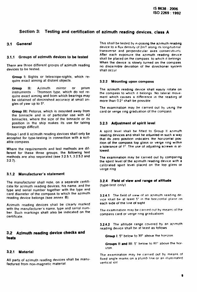
Section 3: Testing and certification of azimuth reading devices, class A
3.1 General
3.1.1 Groups of azimuth devices to be tested
There are three different groups of azimuth readingdevices to be tested .
Group I: Sights or telescope-sights, which require exact aiming at distant objects .
Group II : Azimuth mirror or prisminstruments - Thomson type . which do not require exact aiming and from which bearings maybe obtained of diminished accuracy at small angles of yaw up to 5°.
Group 11/ : Pelorus. which is mounted away fromthe binnacle and is of particular use with A2binnacles , where the size of the binnacle or itsposition in the sh ip makes its use for takingbearings difficult.
Group I and II azimuth reading devices shall only beaccepted for type-testing in connection with a suitable compass .
Where the requirements and test methods are different for these three groups. the following testmethods are also separated (see 3.2.5.1, 3.2.5.2 and3.2.7).
3.1.2 Manufacturer's statement
The manufacturer shall note. on a separate certificate for azimuth reading devices. his name. and thetype and serial number together with the type andcard diameter of the compass to which the azimuthreading device belongs (see annex B)
Azimuth reading devices shall be clearly markedwith the manufacturer's name. type and serial number. Such markings shall also be indicated on thecertificate .
3.2 Azimuth reading device checks andtests
3.2.1 Material
All parts .of azimuth reading devices shall be manufactured from non-magnetic material
This shall be tested by exposing the 8lfmuth rf'8dmgdevice to a nux denSIty of 2mT along Its longItud Ina ltransverse and perpendicutar a)(1'5 consecunvetvAfter each exposure the aztrnutn reading deVICeshall be placed on the compass to whICh It belongsWhen the device is slowly turned on the compassno discernible deviation of the directional systemshall occur
3.2.2 Mounting upon compass
The azimuth reading device shall eaSIly rotate onthe compass to which It belongs No lalpral movement wh ich causes a difference ,n the readln~ ofmore than 0.2 0 shall be possrbre
The examination may ttl' earned out by uSing thecard or verge ring graduation of the compass
3.2.3 AdJustment of spirit level
A spirit level shall bl' fllted to Group II allmuthreading devices and shall be adjusted In such a waythat its zero position Indlcall's the hori/onl.l position of Ihe compass lop gIlts!! or verge rlno wllhllla tolerance of 1' . The USf' of adjusltng Icrewl' IS atlowed.
The examination may be earned out by comparingthe SPirit level 01 the aZImuth reading device With acalibrated spirtt level placed on the lop 111:1'15 orverge ring
3.2.4 Field of ylew and range of altftYd.(type-test only)
3.2.4.1 The field 01 VIf>W 01 an "'lmulh "';ld lng d~ ·
vice !;h;J1l bp at leao;I 5' In the hOfl/onl;l1 planp oneach side of the line of SIQhl
The eX;Jmln:llton mav bl' c:lml' d out hy means o f fhl'compass card or verge rlnll gr<ldu:lllonS
3.2.4.2 The altitude range covered by an allmuthreading device shall hI' at least as follows
Group I: S~ below to 30" above the honzon
Groups " and III : 5' below 10 50' above the norizon .
The e)'aminalion ma y he earned out hy means 01Ii)(ed angle mark", on a plumb line o r an illulTll!'l;Jtf> dver1IGII ",III
•
IS 8638 : 2006ISO 2269 : 1992
3.2.5 Accuracy
3.2.5.1 Sights with or without prismatic magnifyingglass ('or card readings)
3.2.5.1.1 Parallelism of vanes
The vert ical bea r rnq thre ad of the ob ject vane andthe slit of the eye vane sha ll be parallel to eachother
The exarmnanon sha ll be carried out by observation
3.2.5.1.2 Perpendicularity of vanes upon base
The plane of Sight defined by the object and eyevanes shall be perpendicular to the top glass or tothe verge rrng of the compass respectively In addit ion the plane of Sight shall pass through the rotanon axis of the azim uth reading de vice and shallcon tain th e horrzontal bearing thre ad for cardbea rings as well as the Index m ark for bearingsrelahve to the sh ip 's head on the verge ring graduanon
The e xamination for perpendicularity of the vanesmay be carried out by viewing a plumb line or an i lluminated vertical slit and by reading the bearing onthe gradualton Then the sight sha ll be turned ex acll y 1800 and Viewed again through It In the reversernr ecnon If the object IS st il i par all el With the vanesand strll lie!': In the plane of Sigh! . the vanes areperpend icular to thf' planp o f rotat ion At the s amel imp il IS verified thaI the plane of <; ight Pil<;Sf''\through the rotat ron a)(I'\
NOTE ) Aa.1 oS n""".""y lo r Ih, . 1...1 Ihal Ihe qr adu .IIon ,,,onllf' lotls ... .octly ,n the rolahon a ••a IN:c,,n r''cil ybf'f ow 0. 1 m m !. Ih" In.1 molY"'" c...""d 001 on a ap<'C.alI... , .I .,nd wllh appl iance. sUllahl" lor a:,mulh r.. adinqrfflv,'''. 0 1 .,11 t yp"o
3.2.5.1.3 Attachment and adlustrMnt of observationmirror
Thf' m irror. If fitted . u'\ed 10 takf' hparing<; of high;tl t l t ud e o bj ect s sh all be allach f'C:! il n d ad just ed Insuch a way Ihat the rene cnon plan e IS parall el to Ihep lane of <;Ighl in ,l ny posinon 10 With in th l' toterancesg iven In tabl e 2 If the m irror IS of the b" .lt N al type .!' ac h of the lWo mirror Sides sha ll ful fil these re q uir ern ents The use of ad just rnq tco rrectrom screw sIS allowed
The p" am lna!lo n Shill l be carned out by observ at ionWhen incl ining Inp. m ir ror. Ihe verti cal bea rin gth rea d and it s re fle cl ed Im age sha ll remain In co,nCldenr e
10
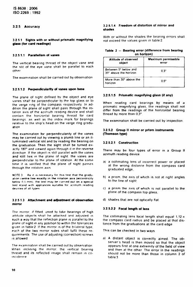
3.2.5.1.4 Freedom of distortion of mirror andshades
With or w ithoul th e shades the bea ring errors shallnot exceed Ihe valu es given in table 2
Table 2 - Bearing error (difference from bearingon horizon)
AltItude of observed Maximum permissibleobJect error
Between 5" below and 0.3'30' above the horizon
More Ihan 30' above the 0.5'horizon
3.2.5.1.5 Prismatic magnifying glass (if any)
When read ing card bearings by means of aprismatic magnifying glass. the readings shall notdiffer from the readings of the horizontal bearingthread by more than 0,3°.
The examination shall be carried out by inspection .
3.2.5.2 Group" mirror or prism Instruments(Thomson type)
3.2.5.2.1 Construction
There may be four types of error in a Group IIazimuth read ing device
a) a co llimating lens of Incorrect power or placedat the wrong dislance from the compass cardgraduated edge:
b) ::I pnsrn . the ::IXIS of which is not at r ight ang lesto thl' li ne of sight.
c) a pr ism Ihe axis of which is not parallel to theptane of Ihe compass top glass :
d) shades that are not optically flat
3.2.5.2.2 Foca' length of 'ens
The co ll im ali ng lens focal lenglh sha ll equal 1.12 xIhe compass card rad ius and be placed at that distance from the graduations at the card edge .
This can be checked in two ways
a) A distant ob ject is correctly aimed . The observer 's head is then moved so that the ob jectappears first at one extremity of the field of viewand then at the other The error in the readingsshou ld not be more than those in column 2 oftable3
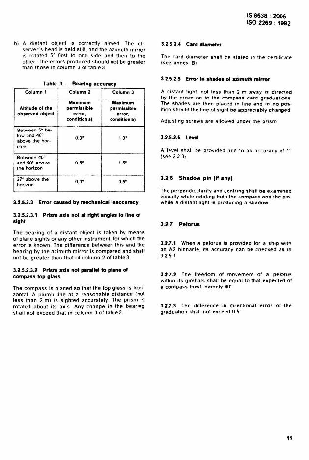
b) A distant object is correctly aimed The ob se rver 's head is held still. and the azimuth mirroris rotat ed 5° first to one side and then to theother The errors produced should not be greaterthan those in column 3 of table 3.
Table 3 - Bearing accuracy
Column 1 Column 2 Cotumn 3
Maximum MaximumAltitude of the permissible permissible
observed object error. error.condition II) condltlonb)
Between 5' be-low and 40' 0.3' 1,0'above the hor-izon
Between 40'and 50' above 0.5' 1.5'the horizon
27' above the 0.3' 0.5'horizon
3.2.5.2.3 Error caused by mechanical Inaccuracy
3.2.5.2.3.1 Prism axis not at right angles to line ofsight
The bearing of a distant object is taken by meansof plane sights or any other instrument. for which theerror is known The difference between this and thebearing by the azimuth mirror is compared and shallnot be greater than that of column 2 of table 3
3.2.5.2.3.2 Prism axis not parallel to plane ofcompass top glass
The compass is placed so that the top glass is horizontal. A plumb line at a reasonable distance (notless than 2 m) is sighted accurately . The pr ism isrotated about its axis Any change in the bearingshall not exceed that in column 3 of table 3.
IS 8638 : 2006ISO 2269 : 1992
3.2.5.2.4 Caret dlamet.,
The card diameter sh,,11 \lP stated In thp cert lflcale(see annex Bt
3.2.5.2.5 Error In shades of ulmuttl mirror
A distant li ght not less than 2 m "way is dIrectedby the prism on to thf" compass ca rd graduationsThe shades are thf"n placed In hne and In no posilio n should the hne of lOlght be apprf"Ct8bly chllngl"d
Adlustlng screws ar e allowed under the pr ism
3.2.5.2.6 Level
A level sha ll be provided and to an accuracy ot , .(see 323)
3.2.6 Shadow pin (if any)
The perpendicularity and (f~ntrtng sha ll be examinedVisually whi le rotatmg both 1he COmp8!i5 and th .. pm .while a distant light IS producmg a shadow
3.2.7 Pelorus
3.2.1.1 When a pelorus flO prOVided for" shtp Withan A2 binnacle. Its accuracy can be checked all In325 1
3.2.1.2 The freedom of movement or a peloruswith in its gimbal s shall hp. equal to Ihal ellpedf'd ora compass bowl . namely 40 °
3.2.1.3 The differenCe in dlrecttonal __ rror 01 thl'qr aduation shau not f'xcped 05'
11
IS 8638 : 2006ISO 2269 : 1992
Sedion 4: Type-testing and certification of class A binnacles
4.1 General
Type -les"ng shall be earned out before the binnaclecomes rnto regu lar servrce . Each binnacle shall beprovided w ith Its co m pas s, azimuth readinq device,correctors and , If fi tted , a transmitt ing system . Ind ividual testmg of bmnacles and correcting dev ices isnot required
New devices on ly are accepted fo r type -testing
4.1.1 Binnacles and correcting devices to betested
Type-test ing should be ca rr ied out on all binnaclesand correcting devices These include binnacles forprojector. reflector or transmi tti ng compasses ,
There are two typ es of class A binnacle to be tested ,
Type A1: A binnacle of such a design and he ightthat the magnets of the compass directional system shall be at least 1 m above the undersurfaceof the bi nnacle de ck fitt in g
Type .\2: A binnacle which may be used wherea type A 1 binnacle is unsuitable The binnaclehe ight is not specified
Where the requirements and test methods are dif'erent for the,e two types . the test methods arespeCified sep arately for A 1 and A2
It IS perrn is srble to suppl y the A2 binnacle Withoutquadrantal correctors and Without Fllnders ' s bar , butwhen the re IS provision for fltllng these cor rectors.both shall be provided when the binnacle is submitted for type appro val
4.1.2 Manufacturer's atatement
The manufa ct urer C;h il ll produce a written statementcovering those reqUirements that cannot be ascertained dur ing the tv ne -te st This statement shallcontarn the follOWing oomts
8 ) the vert ic al distance between the rmd -ptane ofthe directional sys tem magnets and the gimbalbearings centre of the compass supplied:
bl that w ith the exce ptio n of the correcting dev ices(and where appropriate. certain parts of thecompass transrnission system). the binnaclesand fitt ing s are free from milgnetic material ,
c ) when natural wood IS used fo r the exterior of thebinnacle It 1$ seasoned tro pical hardwood (fo rexample . teak) Any other wood used In the
12
binnacle is to be seasoned hardwood. or marineply When a material other than wood is used. itsproperties are to be stated ;
d} all materials used are of sufficient strength ;
e} the coercivity of the corrector magnets :
f) that the material used for correct ing inducedfields has a high permeability. a low coercivityand a negligible remanence;
g) where wooden parts are joined by an adhesiveonly. the type of adhesive used,
4.1.3 Markll'lg
Binnacles shall show in a conspicuous posit ion thename of the manufacturer or importer or othermeans of identification of orig in together w ith typemarking,
The marking shall be noted on the type-test certificate (see annex C).
4.2 Binnacles
4.2.1 Construction and material
4.2.1.1 Dimensions
In binnacles type A1. the directional system magnetsshall be at least 1 m from the underside of thebinnacle deck fittings.
4.2.1.2 Non-magnetic properties
As the manufacturers have given a guarantee declaration . only sample checks are necessary.
4.2.2 Compass suspensIon
4.2.2.1 Outer gimbal axis
The axis shall be in the binnacle fore and aft linewithin 0.5° ,
4.2.2.2 TIh of supporting device
The compass verge ring shall remain horizontal toWithin 2° when the binnacle is tilted 40° in any direct ion
Where there is no or negligible lateral play in thesuspension. th is can be tested by tilling the compassbowl, while the binnacle remains horizontal andmeasuring the angle with a clinometer Should the
compass be mounted in a flexible suspension orcontrolled by springs , then it is necessary to tilt thebinnacle and for the compass to remain horizontal.This measurement should be taken both with andwithout the azimuth reading device or other attachment (for example magnifier or Ouxgate) in position
• .2.2.3 Precautions against dislodging
The compass shall be secured against dislodging inany cond it ions of sea or weather. This securing shallnot impair the compass in the free movement withinthe limits of 4.2.2.2.
• .2.2.4 Friction 01 gimbal and compass axes
When the compass bowl is inclined 5° in any direction and released. it shall return to within 2° of thehorizontal plane.
This measurement should be undertaken with asuitable level and with az imuth reading device andany other fittings which may sometimes be attachedin position and also without them .
•.2.2.5 Play In outer gimbal axis bearing
The outer gimbal axis shall not be able to movewithin its bearing more than 0.5 mm in a fore andaft direction.
The measurements may be carried out by means ora reeler gauge.
•.2.2.6 Compass suspensions provided withsprings
• .2.2.6.1 Horizontal movement of compass bowland gimballlng
The horizontal movement or the bowl and gimballingshall not exceed 5 mm in any direction rrom thenormal position
Thi s measurement may be carried out by means ora gauge or scale . using the binnacle inner rim rorreference .
• .2.2.6.2 Effect of azimuth reading device
The vertical displacement of the compass bowl centre caused by the mass or an azimuth reading de vice shall not exceed 3 mm.
The measurement may be carried out by means ofa gauge or scale. using a su itable horizontal planefor reference .
IS 8638 : 2006ISO 2269 : 1992
4.2.3 Provisions to correct ml.allgnment
4.2.3.1 Fore and aft mark' provided on binnaclesshall be in the same vertical plAne to Within 0.5" asthe aKis of the fore and aft gimbal beanngs
The examination may be cArned out WIth thp atd ofa plumb line and With lhe compass In the binnacle
• .2.3.2 In type "1 binnactes . provis ions shall bemade for any misalignment in respect of the foreand aft line of the ship by turning the binnaclethrough an angle of not less than .co and not morethan 6". This requirement is not obllgalory in typeA2 binnacles. The examination may be earned outwith the compass in the binnacle
4.2.3.3 The course as read from Ihe projected irnage shall agree with the course reitd at the mainlubber mark to WIthin 0.5"
4.2.4 Correcting devlc:ea. marking, coerdvltyand securing
Corrector magnets shall he mltrked red at the northseeking end and sh:"l have a coerctvity of no! lessthan 11 200 Aim
All fittings carrying correcnon deVices shall besecurely Joined to the binnacle and well protecl-:daga inst sea and weather .
Suitable devices (lor mstance a SCale) to indicateIhe position 01 the correcting devices al any giventime shall be provided Holes or grooves used lorhorizontal corrector magnet5 shall be numbered andthe numbers shall read from the bOMom upwards
Provisions shall be made 10 secure the correctingdevices of Ihe binnacles aga inst unAuthOflze<l access and unintentional d1spl:lcemenl
The examination shall be carned out VISually
4.2.4.1 Heeling error cOfTKtor~
Heeling magnets shall be able 10 produce a vert,calnux density over the range ... 7S liT to + 7S I£T at Ihedrrecnonat syslem magnels
This can be checked by using a venlCR' Iorce mstrument or any other milgnelometer or by measuring the magnelic momenl and calculat ing the fieldintensity
The tube provided lor one or more heeling errormagnets to correct Ihe innuence of vertICalmagnetism shall be filled centrally below the compass bowl in the binnacle venlcal aXIs. unless asu itable s~cilll deVice is fitted When several heeling error magnels are provided for . the caStngs shallbe constructed so thai the magnets can be placedIn a symmetncal arrangement abOUt ," axis . The
IS 8638 ; 2006ISO 2269 ; 1992
hee ling error magnet , or the holder for the heelinger ror ma gnets re spect iv ely , shall be capable of be Ing safely secured In POSition by some suitablemeans Prov ision shall be made so Ihatthe distancebetween the upper end of the correct ing magnetsand the magnets 01 the directional system cannotbe less than tWice the length of the correcting magnets In class A 1 binnacles
In type A2 binnacles. no prec ise dimensions are requrred. but the elfect on the directional system shallnot be any less favourable In part icular. provis ionsha ll be made so that no correcting system magnetscome so close to the directiona l system as to distortthe field and produce a dev iat ion of more than180 / I n" on any course where there is a heel or pitch0115"
The examinat ion in the case of the type A1 binnacleshall be carried out by inspection
In the case 01 the type A2 binnacle. which will besmaller. it may be necessary to provide means forchanging the vert ica l field in the vicinity of the direct io nal element The field thus produced is to becorrected With the heeling magnets. and thebinnacle t ilted 15° The result ing deviation shall notexceed (801mO
• .2.• .2 Mounting of horizontal corrector magnets
• .2.4.2.1 Error of .1I~nment
The directron 01 the fore and an and thwartship corrector magnets shall not dev iate more than 2° fromthe direction of the outer gimbal axis or its perpen dicular respect rveiy . and shall be within 2° of thenonzontat
4.2.4.2.2 Posltlon error
Thp holes or grooves for the fOff> and an and for thethwart!lhip co rr ecto r magnets . wh en of the conventionat type . shall be mounted 10 such a manner andhe of such a size that the mid·point of the appropriatp rnaqnets whe n In p lace he s Within 5 mm 01 theve rt ica t planes passing through a thwartship and thefore Rnd art gimbal axes respect ively
NOTE 4 The el;lmin",tIQt'l!l rflQulred by 4;Z 4 ;Z t ",nd4 ;Z 4 '2 '2 mOlY btl c,uriNi out by u~ing a levfliling instrumenl and ,n such a way lhat the "","cal planes passingthrough lhe gtmbal awes are reprl!'5eflled by plumb lines'rom which lhe d's lance measurl!'menl may btl carried out
4.2.4.2.3 Minimum distance of horizontal corrKtIngmagnets from dIrKtionaI system and hIr stNngth
The device shall be capable of correcting a coer fic Ient Rand C of at least (72O!/f) "
In type A1 binnacles. the holes or grooves for thehorizontaf corrector magnets shall be fitted to the
binnacle in such a way that when the compass direct ional system is of the conven tional type . consisting of bar or ring magnets . no magnet of th ecorrect ing system shall lie ne ar er than twice itslength from the direct ional system magnets.
In type A2 binnacles , no precise dimension as to theprox imity of the correcting magnets to the directional element is required. but provis ion shall bemade so that no magnets of the co r recti ng sys temcome so close to the direct ional system as to distortthe field and produce a deviation 01 more tha n(40/1f)° on any cou rse with a heel or p itch of 15°.
The amount of deviation that can be corrected by thecorrector magnets can be measured by placing th ema ximum number of correcting ma gnets in th ethwartship direction setting the compass on thecorrector stand in its binnacle and aligning it onnorth or south . The angular difference between thestand alignment and the magnetic north or scuthind icates the correcting power of the magnets. Thisshould be repeated on east or west using the foreand an magnets.
The distance of the magnets from the directional element in a type A1 binnacle shall be measured .
In a type A2 binnacle. the compass in its binnacle isplaced on the test stand and aligned o n north orsouth . An external magnetic force sufficiently faraway to create a reasonably even field in the vicini tyof the directional element is applied until a deviationof (7201In° is obtained . This deviat ion is then corrected by the magnets in the binnacle . The binnacleis tilted 15°. The result ing deviation shall not exceed(40lmO
Repeat on east and /or west .
•. 2.4.3 Attachment of quadranlal correctors
In the case of a type A1 binnacle. th e Quadrantalcorre ctors shall be capable of correct ing a deviationof up to 10"
In the case of a type A2 binnacle , when quadrantalcorrectors are supplied. they shall be capable 01correct ing a deviation of up to I" ,
In both cases when the binnacle axes are vert ica l.the dev ice centre sha ll not be more than 15 mmfrom the horizontal plane passing through the ce ntreof the directional system magnetic element .
In both cases. the axes of the correctors shall befi~ed ~ n such a way that they can be moved in thedirection of their axis along a binnacle diameter .wh ich shall not deviate more than 2" from the direction of the athwartship gimbal ax is .
Al ignment errors can be checked by means of thecard or verge ring graduations.
The amount o f devi ation that can be corrected canbe checked by placing the compass and binnacle ona test stand on a quadrantal course with and withoutthe correcto rs in pos it ion
The heig ht of the correctors relat ive to the directiona l el em ent ca n be che cked by measuring thedistan ce of the dev ice centre from the inne r gimbalaxis and apply ing the info rmat ion provided by themanufacturer.
4.2.4.4 Flinders's bar
Wit h a type A1 binnacle. a Flinders 's bar shall beprovided . With ty pe A2 binnacles . a Fl inders 's barmay be provided where requ ired .
4.2.4.4.1 The line connecting the vert ical axis of theFlinders 's bar to the compass cen tre shall not deviate more than 2° from the direction of the fore andaft gimbal axis .
4.2.4.4.2 The top end of the bar shall be 1/12 of itslength (wi th a tolerance of ± 10 mm ) above thehorizon ta l plane passing through the cen tre of thedirect ional system magnets. If a hollow Flinders'sbar is used . the diameter of th e ho le shall not exceed 40 % of th e diameter of the bar.
4.2 .4.4.3 Minimum distance from card centre
The distance of the vert ical ax is of the Flinders 'sbarfs) from the card centre shall be at lea st250 mrn , but preferably 350 mm .
NOTE 5 The examination may be carr ied oul by usinga metre scale.
IS 8638 : 2006ISO 2269 ; 1992
4.2.5 Corrector colis
C.2.5.1 PrOVISion may he made lo r the tilling 0'cor rector Cal ls to provide cornpensanon " lhl' shIpis fitted With dega USSing Calls
4.2.6 illumination
The binnacle shall contain adpQuale provisron tor d ·
lum inating thp eard by me ans 0 1 l he Shlp's .. I('el"esupply and Irom an emergency ligh t !'>QlHCe In pro jecto r and refle ctor bin nacles . these sha ll provide aclea r image at th e hf' lm sman S posmon De vt r esshall be pro vided for dIm ming the ,lIumlnallon alboth the he lm sman 's posit ion and the binnacl e
4.2.6.1 Magnet!<: Influence of lamps. plugs. soetets.switches. dimmers and wiring
The lamps plugs soc ke ts swucnes dimmers andwir ing . whether energi lf'd or not sha ll ha ve noperceptible magnetic efte c! on the compass on anyheading
The exam in ahon can be earned ou t by tria l
C.2.6.2 Readability of ren.ctor and proiedorcompasses
In compasses 01 the rf' nf' clor o r proje r tor typf' . th..optical ~y~tem ~hall be such thaI thr Image 01 fh l"lubber mark and <I sector at the card 15° on ell herside of the tubber mark shall allow a person withnormal vision 10 read the r ard both In daylight andartific ia l light at <I di stan ce 01 1 m trom the pert&copetube
15
'S 1638 : 2008'SO 2269 : 1992
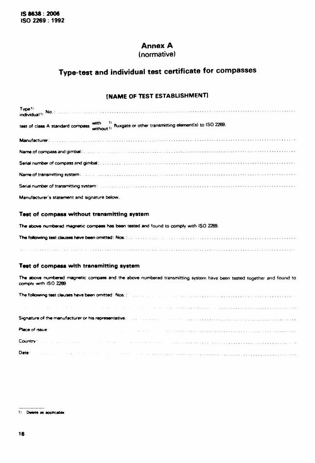
Annex A(normative)
Type-test and individual test certificate for compasses
[NAME OF TEST ESTABLISHMENT]
Type II
individual ! ' No. :
test of class A standafd compass ~:: fluxgate or other transmitting elementls) to ISO 2269.
Manufacturer :
Name of compass and gimbal : .
Serialnumber of COfTlP<ISS and gimbal :
Name of transmitting svstem : . .
Serialnumber of transmiulng system : . .
Manufacturer 's statement and signature below.
Tnt of compass without transmitting system
The IItlcMI numt-ed magnetic compaa has~ tested and found to comply with ISO 2269.
The following test dIIuses haw~ omitted : Nos. : . . . . . .
Tnt of compass with transmitting system
The Ibow numt-ed magnetic compaa and the above numbered transmitting system have been tested together and found tocompIv WIth ISO Z2ftl.
Sognature of the rnanuf8eture< or his representative :
Place of ,~e .
Countrv ·
Date ·
" o.Mle.~
15
IS 8631 : 2001ISO2269 : '"2
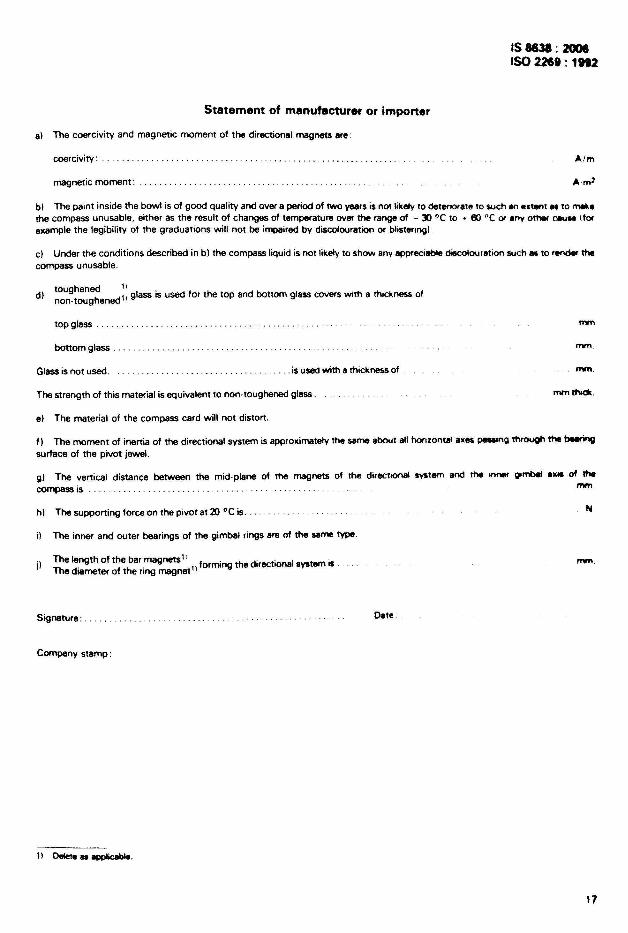
Statement of manufacturer or importer
al The coercivity and magnetic moment of the directional magnets are:
coercivity: ...
magnetic moment:
Aim
bl The paint inside the bowl is of good quality and over a period of two years is nOI ~kely to detenor.le to $Uchan ••tenl .. to mlll<.the compass unusable, either as the result of changes of temperature over the range of - 30 °C 10 .. III °C 0/ any othat eauM itorexample the legibility of the graduations will not be impaired by discolouration or blistenngl
c) Under the conditions described in b) the compass liquid is not likely to show any appreciable discolour.tion $UCh .. to render thecompass unusable.
toughened 1)d) h ed!' glass is used for the top and bottom glass covers with a thickness of
non-toug en
top glass .
bottom glass .
mm
mm
Glass is not used. ....... is used with a thickness of mm.
The strength of this material is equivalent to non-toughened glass
e) The material of the compass card will not distort.
mmthod< .
f 1 The moment of inertia of the directional system is appro.imately the same about all honzontal axes~g through the~surface of the pivot jewel.
g) The vertical distance between the mid-plane of the magnets of the directIOnal ~tem and the InnlIll gomblll .... of thecompass is mm
h) The supporting force on the pivot at 20 °C is.
i) The inner and outer bearings of the gimbal rings are of the same type.
).) The length of the barmagnets1
: formin the directional system is .The diameter of the flng magnet1) g
Signature: .
Company stamp:
, I Delete as applicable.
Date .
N
mm
17
IS 8638 : 2006ISO 2269 : 1992
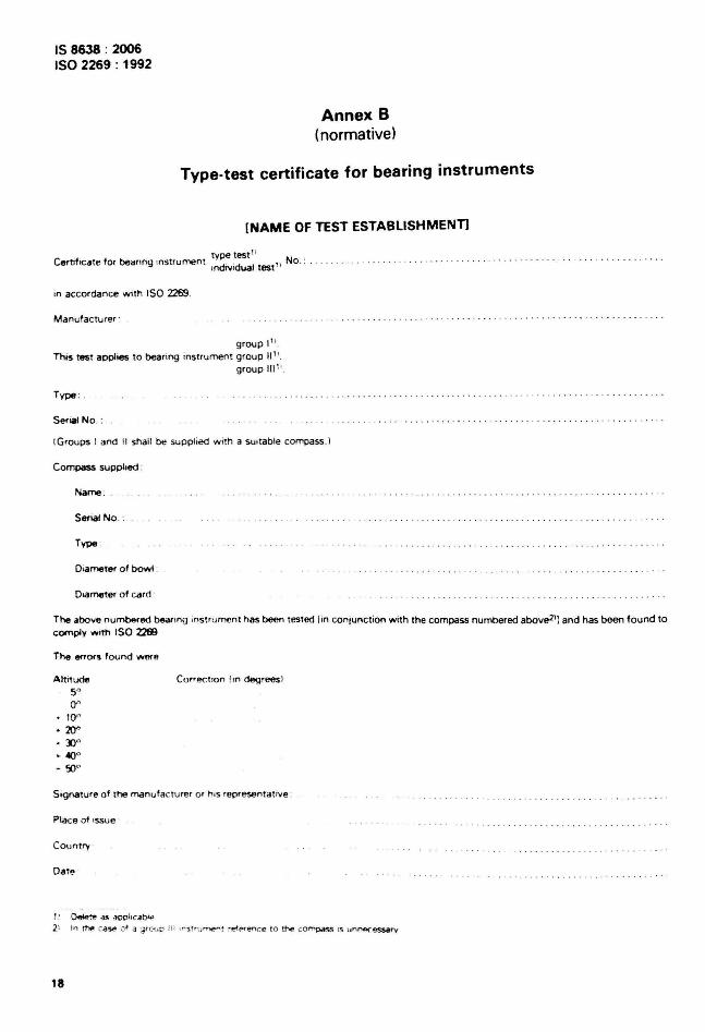
Annex B(normative)
Type-test certificate for bearing instruments
(NAME OF TEST ESTABLISHMENTI
type test "Certif icat e for bearing mstruroent tndN idual test " No . : . .
in accordance with ISO 2269.
Manufa ctu rer ·
group I " .This test applies to bear ing inst rument group \11 !.
group 111 1' .
Type : .
Serlll! No. :
I Groups I and II shall be supplied w ith a suitab le compass.I
Compass supphed :
Name :
Serial No ·
Type .
Olilmeter of bowl :
Dlilmeter of card
The above numbered be.lfIng inst rumen t has been tested l in conjunc t ion with the compass numbered above21] and has been found tocomply WIth ISO Z269
The enors found _eAltIt ude
500"
10"
• 20"• JO"• 4()"
• 50"
Cor- ecnoo li n degreesl
Sig nature of the man uf acturer or h ,S represent at ive :
Place of rssue
Country
Date
,! ~t~ as ~OOhc.db'~
2\ In t~ c.a~ .J' .] ';; r C'\ IC H; ,,.·srrun,e.... r ~~~ence to t~ CO~ rs :.Jn~essarv
18
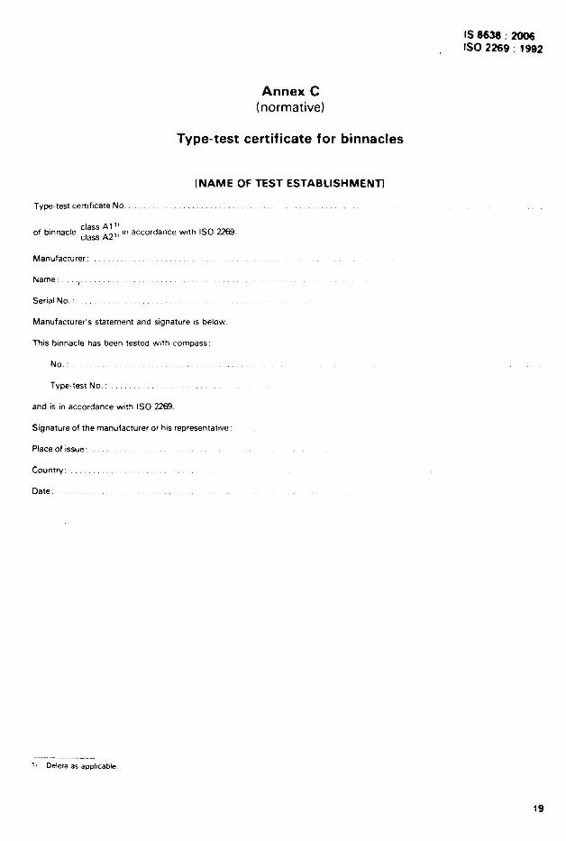
Annex C(normative)
Type-test certificate for binnacles
[NAME OF TEST ESTABLISHMENTI
Type-test certificate No .
. I ctass Al ' d ·hIS02269of binnac e class A2' I In accor ance Wit
Manufacturer:
IS 8638 : 2006ISO 2269 : 1992
Name: .,,"Serial No.:
Manufacturer's statement and signature is below.
This binnacle has been tested with compass:
No.:
Type-test No. :
and is in accordance with ISO 2269.
Signature of the manufacturer or his representanve:
Place of issue:
Country:
Date:
1, Delete as applicable
19
IS 8638 : 2006ISO 2269 : 1992
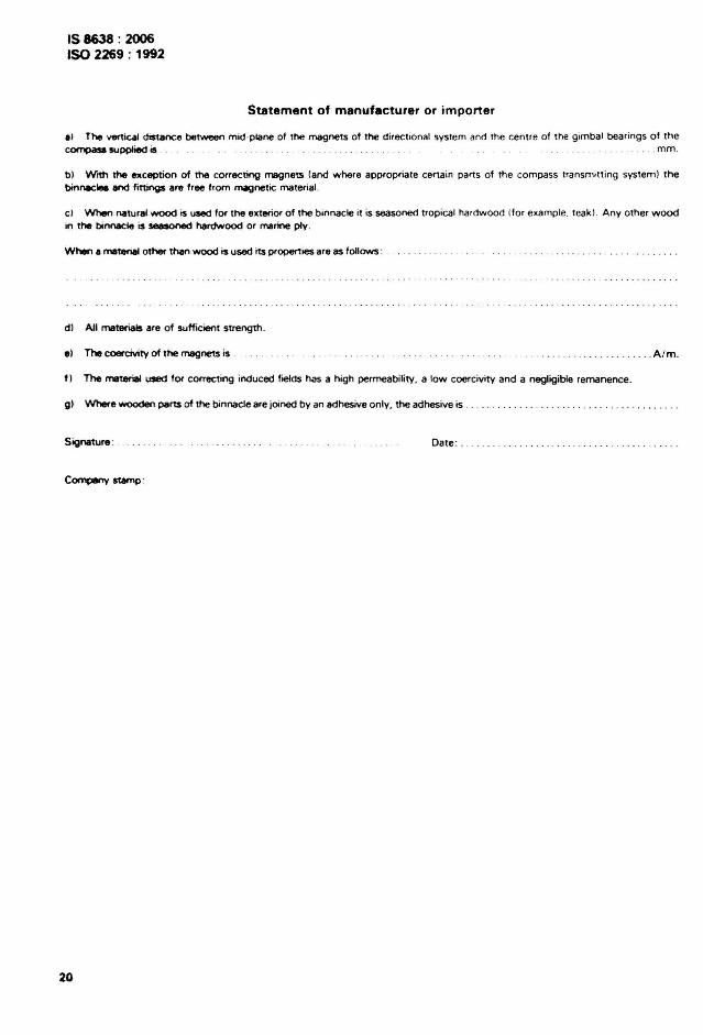
Statement of manufacturer or importer
II The ~cal dIStance between mld ·plane of the magnets of the direct ional system and the centre of the gimbal bearings o f theCOfTlPCtU supplied is . mm.
b) With the exception of the correcting magnets land where appropriate certain pails of the compass transm itting system ) thebinneclell and fittings are free from magnetic materia l.
c l When natural wood is used for the exterior of the binnacle it is seasoned trop ical hardwood Ifor example. teak l . Any other woodin the binnecle is seasoned hardwood or marine ply .
When a material other than wood is used its properties are as follows : .
dl All materials are of sufficient strength.
e) The coereivity of the magnets is .
11 The material used for correct ing induced fields has a high permeability. a low coercivity and a negligible remanence.
g) ~e wooden parts of the binna cle are joined by an adhesive only. the adhesive is .
. ... A /m .
Signature :
Company SllImp '
20
Date : .. . .
IS 8638 : 2006ISO 2269 : 1992
NATIONAL ANNEX A(National Foreword)
A-1 SIS CERTIFICATION MARKING
A-l. l The product may also be marked with the Standard Mark
A-l .2 The use of the Standard Mark is governed by the provis.ons 01the Bureau a / Indian StandardsAct, 1986 and the Rules and Regulations made the reunde r. The details 01conditions under which thelice nce for the use of Standard Mark may be granted to manul acturers or producers may be obtainedfrom the Bureau of Indian Standards.
21
Bureau 01 Indian Standards
BIS IS a statutory Institution established under the Bure:w of Indian Standards Act , 1986 to promoteharm onious developme nt of the acuvines of standardization, marking and qua lity certi ficat ion of
goods and attending to connected matters In the country.
Copyright
BIS has the copynght of all Its publications. No part of these publications may be reproduced in anyform without the prior perrrussion In writ ing of SIS. This does not prec lude the free use , in the courseof irnplementmq the standard, of necessary details, such as symb ols and sizes. type or gra dedesrqnanons. Enqumes relating to copvriqnt be addressed to the Director (Publica tions). SIS.
Review 01 Indian Standards
Amendments are Issued to standards as the need arises on the basis of comments. Standards arealso reviewed penod icalty : a standard along with amendments is reaff irmed when such review ind icatesthat no changes are needed: if the review Indicates that changes are needed, it is taken up for revis ion .Users of Indian Standards shou ld ascerta in that they are in possession of the latest amendments oredition by referring to the latest issue of 'BIS Catalogue' and 'Standards: Monthly Additions' .
This Indian Standard has been deve loped from Doc: No. TED 19 (514).
Amendments Issued Since Publication
Amend No. Date of Issue Text Affected
BUREAU OF INDIAN STANDARDS
Telephones
{2323 76 1723233841
{23:i7 6499 . 2337 856123378626.23379120
Eastern 1 /1 ·~ CIT. Scheme VII M, V.I P. Road. Kankur~achi
KOLKATA 700054
Nor thern SCO 335-336. Sector 34-A. CHANDIGARH 160022
Headquarters:
Manak Bnavan. 9 Bahadur Shah Zalar Marg, New Delhi 110002Ie tepnorics: 2323 0131, 23233375, 2323 9402 website : www.b is.org.in
Regional Offices:
Central . Manak Bhavan , 9 Bahadur Shah Zalar MargNEW DELHI 110002
Southern : C.I.T. Campus, IV Cross Road. CHENNAI 600113
{260 38432609285
{2254 1216 . 2254144222542519,22542315
Western : Manaka laya. E9 MIDC. Maral. Andhen (East) {2832 9295, 2832 7858MUMBAI 400093 2832 7891 , 2832 7892
Branches : AHMEDABAD. BANGALORE. BHOPAL BHUBANESHWAR. COIMBATORE. FARIDABAD.GHAZIABAD. GUWAHATI. HYDERABAD. JAIPUR. KANPUR _ LUCKNOW. NAG PUR.NALAGARH. PATNA. PUNE. RAJKOT. THIRUVANANTHAPURAM. VISAKHAPATNAM.
Pnnled at Srnco Pnntlng Press. Deihl