IS 7615 (2003): System of Cone Tolerances for Conical ... · cone angle tolerances and the...
21
Disclosure to Promote the Right To Information Whereas the Parliament of India has set out to provide a practical regime of right to information for citizens to secure access to information under the control of public authorities, in order to promote transparency and accountability in the working of every public authority, and whereas the attached publication of the Bureau of Indian Standards is of particular interest to the public, particularly disadvantaged communities and those engaged in the pursuit of education and knowledge, the attached public safety standard is made available to promote the timely dissemination of this information in an accurate manner to the public. इंटरनेट मानक “!ान $ एक न’ भारत का +नम-ण” Satyanarayan Gangaram Pitroda “Invent a New India Using Knowledge” “प0रा1 को छोड न’ 5 तरफ” Jawaharlal Nehru “Step Out From the Old to the New” “जान1 का अ+धकार, जी1 का अ+धकार” Mazdoor Kisan Shakti Sangathan “The Right to Information, The Right to Live” “!ान एक ऐसा खजाना > जो कभी च0राया नहB जा सकता ह ै” Bhartṛhari—Nītiśatakam “Knowledge is such a treasure which cannot be stolen” IS 7615 (2003): System of Cone Tolerances for Conical Workpieces from C=1:3 to 1:500 and Lengths from 6 to 630 mm [PGD 20: Engineering Standards]
Transcript of IS 7615 (2003): System of Cone Tolerances for Conical ... · cone angle tolerances and the...

Disclosure to Promote the Right To Information
Whereas the Parliament of India has set out to provide a practical regime of right to information for citizens to secure access to information under the control of public authorities, in order to promote transparency and accountability in the working of every public authority, and whereas the attached publication of the Bureau of Indian Standards is of particular interest to the public, particularly disadvantaged communities and those engaged in the pursuit of education and knowledge, the attached public safety standard is made available to promote the timely dissemination of this information in an accurate manner to the public.
इंटरनेट मानक
“!ान $ एक न' भारत का +नम-ण”Satyanarayan Gangaram Pitroda
“Invent a New India Using Knowledge”
“प0रा1 को छोड न' 5 तरफ”Jawaharlal Nehru
“Step Out From the Old to the New”
“जान1 का अ+धकार, जी1 का अ+धकार”Mazdoor Kisan Shakti Sangathan
“The Right to Information, The Right to Live”
“!ान एक ऐसा खजाना > जो कभी च0राया नहB जा सकता है”Bhartṛhari—Nītiśatakam
“Knowledge is such a treasure which cannot be stolen”
“Invent a New India Using Knowledge”
है”ह”ह
IS 7615 (2003): System of Cone Tolerances for ConicalWorkpieces from C=1:3 to 1:500 and Lengths from 6 to 630 mm[PGD 20: Engineering Standards]

—— ...—-—--——-.——.
IS7615:2003
Indian Standard
SYSTEM OF CONE TOLERANCE FOR CONICALWORKPIECE FROM C = 1:3 TO 1:500 AND
LENGTHS FROM 6 TO 630 mm
(Second Revision)
lCS 17.040.01
0 BIS 2003
BUREAU OF INDIAN STANDARDSMANAK BHAVAN, 9 BAHADUR SHAH ZAFAR MARG
NEW DELHI 110002
December 2003 Price Group 7
Engineering Standards Sectional Committee, BP 20
FOREWORD
This Indian Standard (Second Revision) was adopted by the Bureau of Indian Standards, after the draft finalizedby the Engineering Standards Sectional Committee had been approved by the Basic and Production EngineeringDivision Council.
This standard was first published in 1975 and subsequently revised in 1993. IS 7615 : 1993 ‘System of conetolerance for conical work piece from C = 1:3 to 1:500 and lengths from 6 to 630 mm’ was identical with1S0 1947: 1973 published under dual numbering system. The 1S0 Technical Committee (ISO/TC 213) hadwithdrawn 1S0 1947 : 1973. The Committee, deliberated on the matter and felt that an Indian Standard on thissubject is required to Indian industry. However after withdrawal of ISO 1947: 1973 the dual number status of1S7615 :1993 cannot be continued, therefore, the Committee decided to retain IS7615 and develop an indigenousstandard on the subject as its second revision.
Indian Standard
SYSTEM OF CONE TOLERANCE
IS 7615:2003
FOR CONICALWORKPIECE FROM C = 1:3 TO 1:500 AND
LENGTHS FROM 6 TO 630 mm
(Second Revision)
1 SCOPE
1.1 This standard covers the cone tolerance systemwhich applies to rigid conical work piece from C = 1:3to 1:500 and lengths from 6 to 630 mm.
1.2 The appropriate tolerances of this standard mayalso be used for prismatic work pieces, for examplewedges, etc.
2 BASIS OF THE SYSTEM
2.1 Types of Cone Tolerance
The following four types of tolerance provide the basisof the
a)
b)
c)
d)
cone tolerance system:
Cone diameter tolerance, T~ valid for all conediameters within the cone length L;
Cone angle tolerance, AT given in angular orlinear dimensions (ATa or ATJ;
Cone form tolerance, TF (tolerances for thestraightness of the generator and for thecircularity of the section); and
Cone section diameter tolerance, T... given forthe cone diameter in a defined sectio~. it is validfor the cone diameter of this section only.
2.2 Cone Diameter Tolerance, Cone AngleTolerance and Cone Form Tolerance
2.2.1 Normal cases shall be handled by application ofthe cone diameter tolerance, To only. It includes thetwo tolerances of the types 2.1 (b) and (c). This meansthat the deviations of these two types may, in principle,utilize the whole tolerance space given by the conediameter tolerance, T~.
2.2.2 In case of stronger requirements, the cone angletolerance and the cone form tolerance may be reducedwithin the cone diameter tolerance, T~ by means ofsupplementary instructions. In this case, likewise, nopoint on the conical surface is permitted to lie outsidethe limit cones given by, T~.
2.2.3 In practice, all types of tolerance generally existat the same time and, as far as normal cases areconcerned, each tolerance may occupy a part of thecone diameter tolerance, T~ only in such a way that nopoint on the conical surface lies outside the tolerancespace. In other words, no point on the conical surfaceis permitted to lie outside the limit cones.
2.3 Cone Section Diameter Tolerance
2.3.1 If for functional reasons, the cone diametertolerance is required in a defined section, then the conediameter tolerance, T~s (tolerance type d) shall beindicated. In this case, it is also necessary to indicatethe cone angle tolerance.
2.3.2 If general tolerances for the cone angle arespecified, for example in an any document, and if it isreferred to this tolerance, then it is not necessary toindicate special cone angle tolerances.
3 DEFINITIONS
3.1 Definitions Relating to Cones
3.1.1 Cone
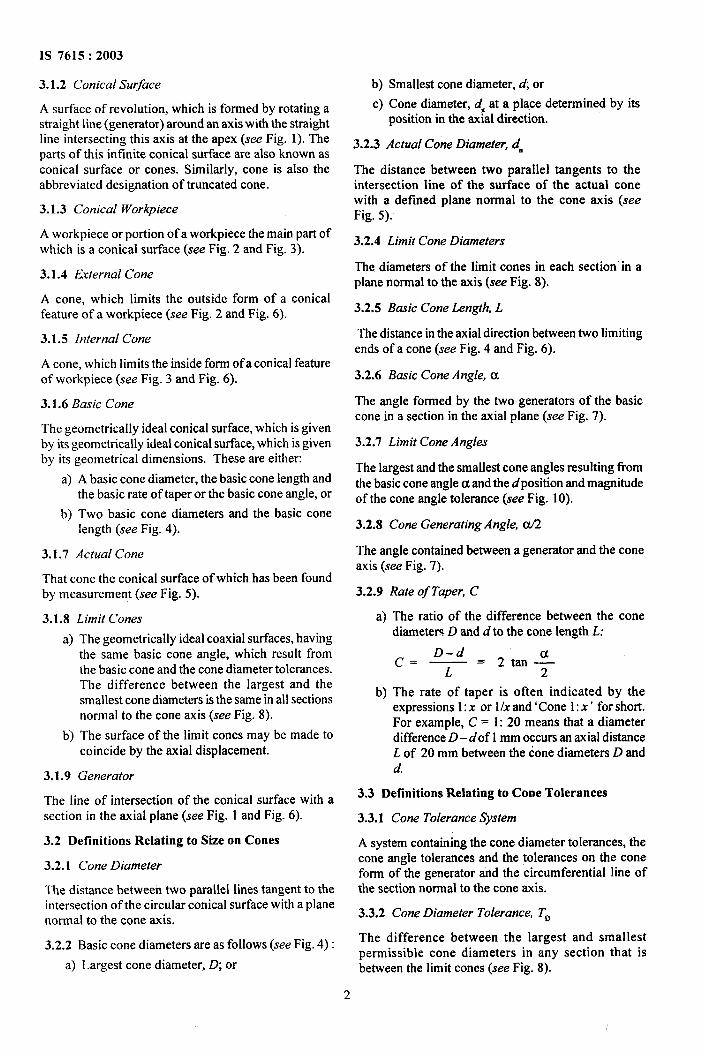
a) A conical surface or a conical workpiece (seeFig. 1) is defined by its geometrical dimensions.
b) In the absence of any indication concerning thegeometrical form, ‘cone’ is understood to meana straight circular cone or truncated cone.
GENERATOR
CONICAL SURFACEAND CONICAL WORKPIECE
FIG. 1 CONE
1
IS 7615:2003
3.1.2 Conical Surface
A surface of revolution, which is formed by rotating astnaight line (generator) around an axis with the straightline intersecting this axis at the apex (see Fig. 1). Theparts of this infinite conical surface are also known asconical surface or cones. Similarly, cone is also theabbreviated designation of truncated cone.
3.1.3 Conical Workpiece
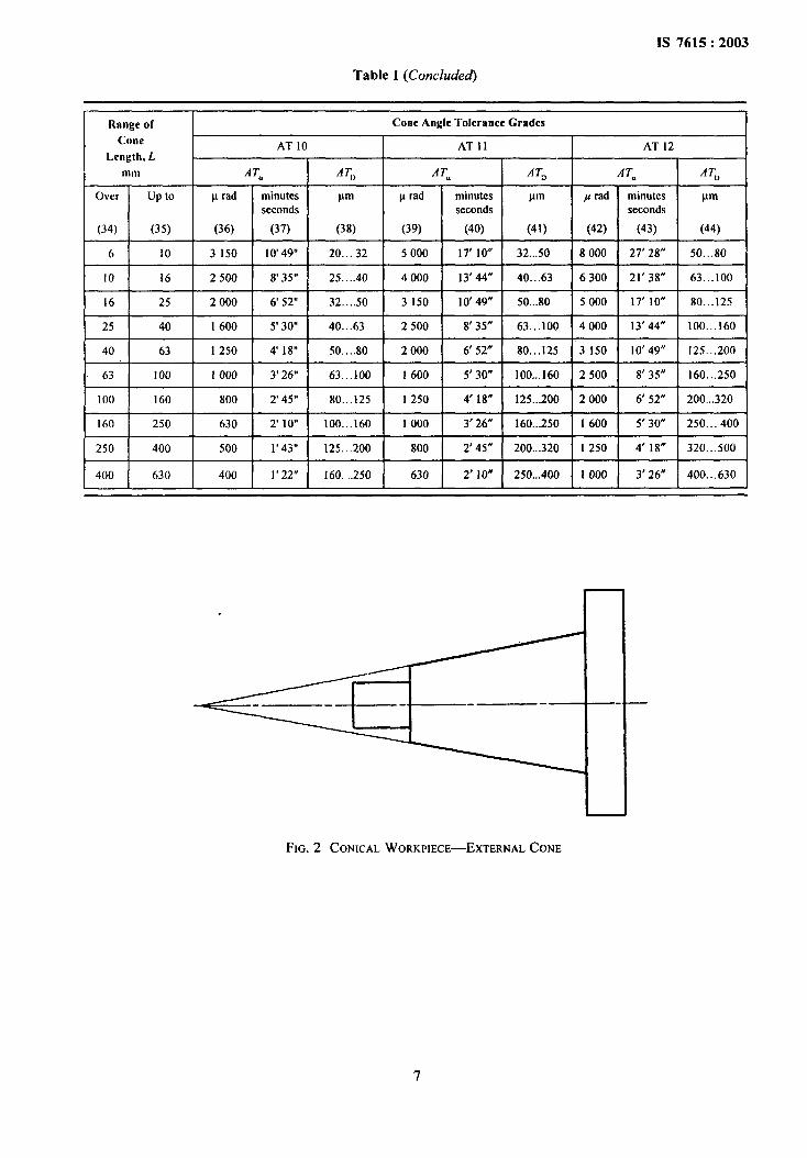
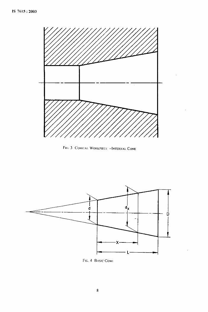
A workpiece or portion of a workpiece the main part ofwhich is a conical surface (see Fig. 2 and Fig. 3).
3.1.4 External Cone
A cone, which limits the outside form of a conicalfeature of a workpiece (see Fig. 2 and Fig. 6).
3.1.5 Internal Cone
A cone, which limits the inside form ofa conical featureof workpiece (see Fig. 3 and Fig. 6).
3.1.6 Basic Cone
The geometrically ideal conical surface, which is givenby its geometrically ideal conical surface, which is givenby its geometrical dimensions. These are either:
a) A basic cone diameter, the basic cone length andthe basic rate of taper or the basic cone angle, or
b) Two basic cone diameters and the basic conelength (see Fig. 4).
3.1.7 Actual Cone
That cone the conical surface of which has been foundby measurement (see Fig. 5).
3.1.8 Limit Cones
a)
b)
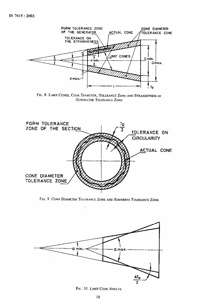
The geometrically ideal coaxial surfaces, havingthe same basic cone angle, which result fromthe basic cone and the cone diameter tolerances.The difference between the largest and thesmallest cone diameters is the same in all sectionsnormal to the cone axis (see Fig. 8).
The surface of the limit cones may be made tocoincide by the axial displacement.
3.1.9 Generator
The line of intersection of the conical surface with asection in the axial plane (see Fig. 1 and Fig. 6).
3.2 Definitions Relating to Size on Cones
3.2.1 Cone Diameter
The distance between two parallel Iines tangent to theintersection of the circular conical surface with a planenormal to the cone axis.
3.2.2 Basic cone diameters are as follows (see Fig. 4):
a) Largest cone diameter, D; or
b)
c)
Smallest cone diameter, d, or
Cone diameter, d, at a place determined by itsposition in the axial direction.
3.2.3 Actual ConeDiameter, d.
The distance between two parallel tangents to theintersection line of the surface of the actual conewith a defined plane normal to the cone axis (seeFig. 5).
3.2.4 Limit Cone Diameters
The diameters of the limit cones in each section in aplane normal to the axis (see Fig. 8).
3.2.5 Basic Cone Length, L
The distance in the axial direction between two limitingends of a cone (see Fig. 4 and Fig. 6).
3.2.6 Basic Cone Angle, a
The angle formed by the two generators of the basiccone in a section in the axial plane (see Fig. 7).
3.2.7 Limit Cone Angles
The largest and the smallest cone angles resulting fromthe basic cone angle etand the dposition and magnitudeof the cone angle tolerance (see Fig. 10).
3.2.8 Cone Generating Angle, w2
The angle contained between a generator and the coneaxis (see Fig. 7).
3.2.9 Rate of Taper, C
a) The ratio of the difference between the conediameters D and d to the cone length L:
D-dc=—= 2 tan+
L
b) The rate of taper is often indicated by theexpressions 1:x or l/x and ‘Cone 1:x‘ for short.For example, C = 1:20 means that a diameterdifference D–dof 1mm occurs an axial distanceL of 20 mm between the cone diameters D andd.
3.3 Definitions Relating to Cone Tolerances
3.3.1 Cone Tolerance System
A system containing the cone diameter tolerances, thecone angle tolerances and the tolerances on the coneform of the generator and the circumferential line ofthe section normal to the cone axis.
3.3.2 Cone Diameter Tolerance, T~
The difference between the largest and smallestpermissible cone diameters in any section that isbetween the limit cones (see Fig. 8).
2
3.3.3 Cone Angle Tolerance A T‘~
The difference between the largest and smallestpermissible cone angles (see Fig. 10, Fig. 15 andFig. 18).
3.3.4 Cone Form Tolerances, T~
3.3.4.1 Tolerance on the straightness of thegenerator
a)
b)
The distance between two parallel, straight linesbetween which the actual generator shall lie (seeFig. 8).
The actual value for the error on straightness istaken as the distance between tw~ parallelstraight lines touching the actual generator, andso placed that the distance be&veen them is aminimum.
3.3.4.2 Tolerance on the circularip of the section
a)
b)
The distance between two coplanar concentriccircles in a section normal to the axis betweenwhich the actual cone section shall be situated(see Fig. 9).
The actual value for the error on circularity istaken as the distance between two coplanarconcentric circles which touch the actual line ofany section normal to the axis.
3.3.5 Cone Section Diameter Tolerance, T~~
The difference between the largest and smallestpermissible cone diameters in a defined section (seeFig. 17).
3.4 Definitions Relating to Actual Cone Angles
3.4.1 Actual Cone Angle
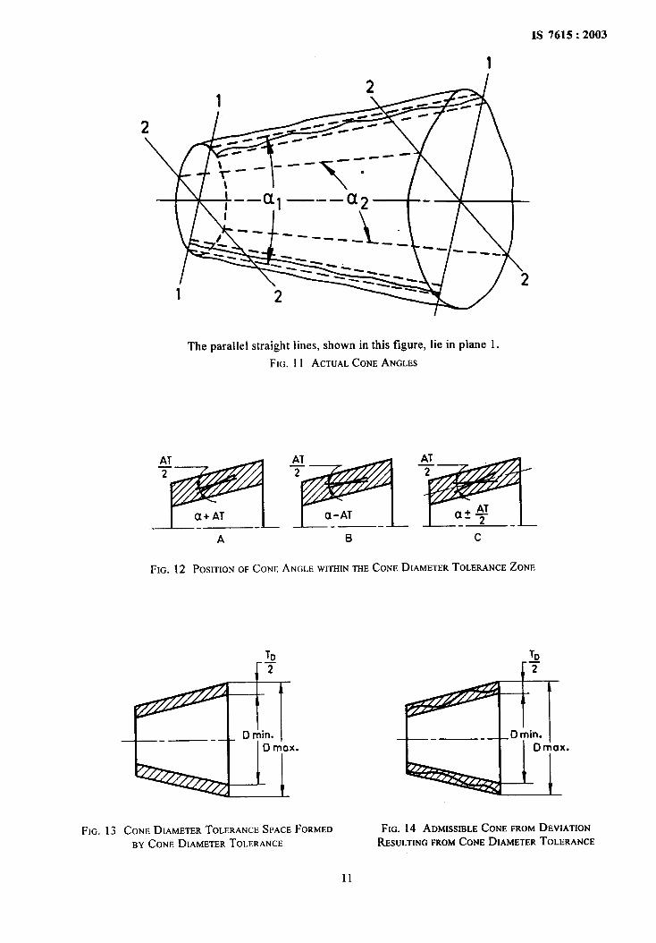
a) In any axial plane section, the angle betweenthe two pairs of parallel straight lines that enclosethe form errors of the two generators in such away that the maximum distance between themis the least possible value (see Fig. 11).
b) For a given cone, there is not only one actualcone angle; for cones having deviations ofcircularity, the actual cone angle will be differentin different axial planes (see et] and a2 inFig. 11).
3.4.2 Average Actual Cone Angle
a) The arithmetical average value of the actual coneangle measured in accordance with 3.4.1 inseveral equally distributed axial plane sections.
b) Amongst the axial planes chosen, one at leastshall cover the greatest deviation of circularityfrom the circle line of the cone diameter.
‘)AT = Angle tolerance.
IS 7615:2003
3.5 Definition Relating to Cone Tolerance Space
3.5.1 Cone Tolerance Space
a) For the conical surface, the space between thetwo limits cones.
b) Cone tolerance space includes all the tolerancesreferred to in 3.3. It may be represented bytolerance zones in two plane sections (seeFig. 8, Fig. 9 and Fig. 13).
3.6 Definitions Relating to Cone Tolerance Zones
3.6.1 Cone Diameter Tolerance Zone
a) In a graphic representation, that zone, lying inthe plane section of the cone axis, which islimited by the limit cones.
b) The total tolerances zone is represented inFig. 8 and Fig. 9 by the hatched portions whichal~oindicate&e cone tolerance space. It includesthe tolerances for the cone diameter, the coneangle, the roundness and the straightness whichcan occupy the whole cone tolerance zone. Ingeneral, each of these particular deviationsoccupies a part of the cone diameter tolerancezone only.
3.6.2 Tolerance Zone for the Cone Angle
A fan-shaped zone within the limit cone angles. Theinclination of the limit cones maybe indicated by plus,minus or plus/minus for the cone angle tolerances (seeFig. 12). For the indication of plus/minus, the valuesmay be different.
3.6.3 Tolerance Zone for the Straightness of theGenerator
a)
b)
In a graphic representation, that zone (band)situated in any axial plane section and disposedon each side of the cone axis, which isdetermined by the form tolerance of thegenerators (see Fig. 8).
As this zone is smaller than that referred to in3.6.1, it only applies if the tolerance on thestraightness of the generator is reduced withrespect to the cone diameter tolerance zone. Theactual generator has to be situated anywherewithin a tolerance zone given by the tolerancefor the straightness.
3.6.4 Tolerance zone for the roundness of the section:In a graphic representation, the zone lying in a sectionnormal to the cone axis and formed by concentric circles(see Fig. 9).
As this zone is narrower than that referred to in 3.6.1 itonly applies if the tolerance for the roundness of thesection is reduced with respect to the cone diameter
3
IS 7615:2003
tolerance zone. The contour has to be situated anywherewithin a tolerance zone given by the tolerance for thecircularity of the section.
3.6.5 Cone Section Diameter Tolerance Zone
The tolerance zone for the cone diameter in a definedsection. It appears in that case if the cone diametertolerance is indicated for fixed diameter only.
4 CONE DIAMETER TOLERANCE, TD
4.1 In general, the choice of the cone diametertolerance, T~ is based on the large cone diameter, D. Itis selected from the Indian Standard IT tolerances andapplies over the whole of the cone length, L
4.2 If it is not required to indicate smaller tolerances ofangle and form, a cone diameter tolerance, T~ given onthe drawing, applies also to the angle and formdeviations. It shall be borne in mind, however, that inthis case all work pieces that conform to Fig. 14 andFig. 15 shall be accepted.
4.3 The symbols of the ISO tolerances system shall beused to indicate the cone diameter tolerances referredto the corresponding cone diameter. If the conicalsurface of the conical work piece concerned isnot intended for a cone fit, the tolerance positions JSand js shall be chosen for preference, for example,40js 10.
5 CONE ANGLE TOLERANCE, AT
5.1 Cone Angle Tolerance Resulting from the ConeDiameter Tolerance, T~
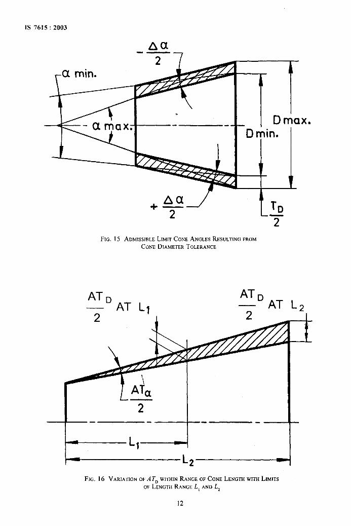
The actual cone angle lies within the cone diametertolerance zone in case of absence of any specialindication of cone angle tolerances. The cone anglesa .,,, and u~in(see Fig. 15) are thus the limit cone anglesresulting from the cone diameter tolerance, T~.Consequently, in this case, the actual cone angle ispermitted to be disposed with respect to the basic coneangle et from + A(x to – Acx(for values of Aa, seeAnnex A).
5.2 Fixed Cone Angle Tolerance
a) If the cone angle tolerance has to be smaller thanthat given by the cone diameter tolerance, it isnecessary to establish the cone angle limits. Forthe cone angle tolerances, the deviations shallbe indicated by plus, minus or plus/minus, forexample, +A T, –A T, + AT12.
b) For the indication of plus/minus, the values maybe different.
6 CONE FORM TOLERANCES, T~
Cone form tolerances comprise the tolerances on:
a) the straightness of the generator (see Fig. 8).
b) the circularity of the cone section (see Fig. 9).
Cone form tolerances shall be especially indicated (inmicrometers), if they shall be smaller than half of thecone diameter tolerance.
7 CONE SECTION DIAMETER TOLERNACE,T
DS
If the cone diameter tolerance should be reduced locallyand shall be given for a defined section only, forfunctional of manufacturing reasons the cone diametertolerance shall be indicated for this section only.
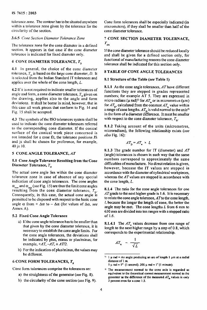
8 TABLE OF CONE ANGLE TOLERANCES
8.1 Structure of the Table (see Table 1)
8.1.1 As the cone angle tolerances, A T have differentfunctions they are stepped in grades representednumbers; for example AT 5. They are expressed inmicro radians (p rad)]) for A T. or in micromet~es (pm)for A T~, calculated from the constant A T=value withina range of cone lengths. A ~~ is valid normal to the axiszlin the form of a diameter ddYerence. It must be smallerwith respect to the cone diameter tolerance, T~.
8.1.2 Taking account of the units (micrometres,microradians), the following relationship exists (seealso Fig. 16):
AT~=AT= x L
8.1.3 The grade number for IT (diameter) and AT(angle) tolerances is chosen in such way that the samenumbers correspond to approximately the samedifllculties of manufacture. No direct relation is given,however, because the IT values are stepped inaccordance with the diameter of cylindrical workpieces,whereas the AT values are stepped in accordance withthe cone length, L.
8.1.4 The ratio for the cone angle tolerances for oneATgrade to the next higher grade is 1.6. It is necessaryto relate the cone angle tolerance, A Tto the cone length,L because the longer the length of cone, the better theangle may be met. The cone lengths L tlom 6 mm to630 mm are divided into ten ranges with a stepped ratioof 1.6.
8.1.4.1 The AT. values decrease from one range oflength to the next higher range by a step of 0.8, whichcorresponds to the experimental relationship.
1AT= - —
G
1)
11
1 p rad = An angle producing an arc of length I ~m at a radialdistanceof 1 m.5 p rad = 1“ (1 second):300 Mrad = 1’ (1 minute).
The measurement normal to the cone axis is regarded asequivalent to the theoretical correct measurementnormal to thegeneratoras the difference of the measuredATD values is only2 percenteven for a cone 1:3.
4
IS 7615:2003
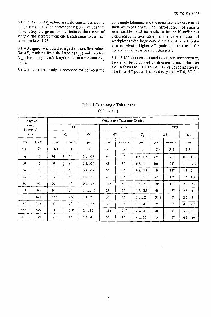
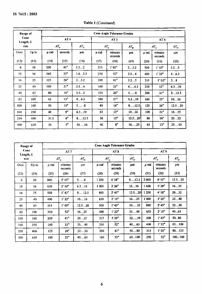
8.1.4.2 As the A Twvalues are held constant in a conelength range, it is the corresponding A 1“~values thatvary. They are given for the limits of the ranges oflengths and increase from one length range to the nextwith a ratio of 1.25.
8.1.4.3 Figure 16 shows the largest and smallest valuesfor AT. resulting from the largest (L~u) and smallest(L~,,Jbasic lengths of a length range at a constant A T.value.
8.1.4.4 No relationship is provided for between the
cone angle tolerance and the cone diameter because oflack of experience. The introduction of such arelationship shall be made in future if sufficientexperience is available. In the case of conicalworkplaces with large cone diameter, it is left to theuser to select a higher AT grade than that used forconical workplaces of small diameter.
8.1.4.5 If freer or coarser angle tolerances are necessary,they shall be calculated by division or multiplicationby 1.6 from the AT 1 and AT 12 values respectively.The finer AT grades shall be designated AT O,AT 01.
Table 1 Cone Angle Tolerances
(Clause 8.1)
[ Range of Cone Angle Toleranee Grades
Cone AT 1 AT 2 AT 3Length, L
mm ATa A~, ATe A TD AT* A TD
Over up to v rad seconds ~m L rad seconds ~m p rad seconds ~m
(1) (2) (3) (4) (5) (6) (7) (8) (9) (lo) (11)
6 10 50 lo” 0.3...0.5 80 16“ 0.5...0.8 125 26,, 0.8...1.3
10 16 40 8“ 0.4...0.6 63 13” 0.6...1 100 21” 1. . ....1.6
16 25 31.5 6“ 0,5,..0,8 50 I o“ 0.8...1.3 80 16“ 1.3,..2
25 40 25 5,) 0.6...1 40 8“ 1..,1.6 63 13” 1.6...2.5
40 63 20 4“ 0.8..,1.3 31.5 6“ 1.3...2 50 1o“ 2 .. . ...3.2
63 I 00 16 3“ 1.. ....1.6 25 5* 1.6...2.5 40 8“ 2.5 . ...4
100 160 12.5 2.5” 1.3,..2. 20 4“ 2 . ...3.2 31.5 6“ 3.2 . ...5
160 250 10 2“ 1.6...2.5 16 3,/ 2.5...4 25 5,, 4 . . ....6.3
250 400 8 1.5” 2,.,..3,2 12,5 2.5” 3.2...5 20 4“ 5. . . ...8
400 630 6,3 1“ 2.5..,4 10 2“ 4 . . ...6.3 16 3“ 6.3....10
1S 7615:2003
Table 1 (Continued)
Range of Cone Angle Tolerance Grades
Cone AT 4 AT 5Length, f,
AT 6
mm AT. ATD AT= ATD ATm ATD
Over up to p rad seconds pm v rad minutes gm A rad minutes ~mseconds seconds
(12) (13) (14) (15) (16) (17) (18) (19) (20) (21) (22)
6 10 200 41” 1.3...2 315 1’05” 2...3.2 500 1’43” 3.2...5
10 16 160 33” 1.6...2.5 250 52” 2.5...4 400 1’22” 4...6.3
16 25 125 26” 2...3.2 200 41” 3.2...5 315 1’0.5” 5...8
25 40 100 21” 2.5...4 160 33” 4 . . ...6.3 250 52” 6.3...10
40 63 80 16“ 3.2...S 125 26” 5.. ....8 200 41” 8...12.5
63 100 63 13” 4....6.3 100 21” 6.3...10 160 33” 10...16
100 160 50 10” 5.. . ...8 80 16” 8.....12. 5 125 26” 12.5...20
160 250 40 8“ 6.3...10 63 13* 10...16 100 21” 16...25
250 400 31.5 6“ 8.. ...12.5 50 lo” 12.5...2 0 80 16” 20...32
400 630 25 5“ 10. . ...I6 40 8“ 16.....25 63 13- 25....40
Range of Cone Angle Tolerance Grades
Cone AT 7 AT 8 AT 9Length, L
mm ATti ATD AT= ATD AT. ATD
Over up to p rad minutes pm ISrad minutes pm /lrad minutes ~mseconds seconds seeonds
(23) (24) (25) (26) (27) (28) (29) (30) (31) (32) (33)
6 10 800 2’45” 5 . . ....8 1250 4’18” 8....12.5 2000 6’52” 12.5...20
10 16 630 2’ Io“ 6.3...10 1000 3’26” 10...16 1600 5’30” 16...25
16 ?5 500 1’43” 8.....12.5 800 2’45” 12.5...20 1250 4’ 18“ 20...32
25 40 400 1‘ 22” 10....16 630 2’1 o“ 16....25 1000 3’26- 2S...40
40 63 315 1’05” 12.5...20 500 1’43m 20.....32 800 2’45m 32...50
63 100 250 52” 16...25 400 1‘ 22” 25....40 630 2’10” 40...63
100 160 200 41” 20...32 315 1‘ 05” 32.....50 500 1’43N 50...80
160 250 160 33” 25....40 250 52” 40....63 400 1‘ 22” 63...100
250 400 125 26” 32....50 200 41” 50....80 315 1’05” 80... I25
400 630 100 21” 40....63 160 33” 63...100 250 52” 100...160
6
IS 7615:2003
Table 1 (Concluded)
Cone Angle Tolerance Grades 1Rfirrge of
Cnrse
Lmrgth, L
mm A TQ
Over I up to p rad minutesseconds
(36) (37)
minutes I pmseconds
p rad Iminutes I pmseconds Ia=(34) (35)
6 10
10 16
16 25
25 40 =E(38) (39)
20...32 5000
25....40 4000
32....50 3150
40...63 2500
50....80 2000 %
(40) (41)
17’10” 32...50
13’44” 40...63
10’49” 50...80
8’35” 63... IOO
6’52” 80...125
=+=
3150 10’49”
2500 8,35,,
2000 6, 52,,
1600 y 30,( 33=6300 21’38” 63...100
5000 17’10” 80...125
4000 13’44” 100...160
3150 1o’49m 125...200
3=40 63
63 100
100 160
160 250
250 400
1250 I 4’18”
2500 I 8’35” ] 160...250 j1000 I 3’26” 63...100 I 1600 5’30” I 100...160
800 ] 2’45” 4’18H I 125...200 2000 I 6’52” I 200...320 ]80...125 I 12501
630 2, ,0,,
-+=-E=1600 5’30” 250...400
1250 4’ 18“ 320...500=-i’==400 I 1’22”400 [ 630 2’10” I 250...400 1000 I 3’26” I 400...630 I160...250 I 630
FIG. 2 CONICALWORKPIECE—EXTERNALCONE
7
IS 7615:2003
FIG. 3 CONICALWORKPIECE—INTERNALCONE
~ L—————iBASICCONE
8

IS 7615:2003
--i
FIG. 5 ACTUALCONE
L CONE
FIG. 6 GENERALDEFINITIONS
GENERATING ANGLE
BASIC ANGLE
1
FIG. 7 ANGLESONCONES
9
1S 7615:2003
FORM TOLERANCE ZONE CONE DIAMETERE ZONE
x.
FIG. 8 LIMITCONES,CONEDIAMETER,TOLERANCEZONEANDSTRAIGHTNESSOF
GENERATORTOLERANCEZONE
FORM TOLERANCE TDZONE O
ON
CONE
CONE DTOLERA
FtG.9 CONEDIAMETERTOLERANCEZONEANDROUNDESSTOLERANCEZONE
ATa
--z-
FIG. 10 LIMITCONEANGLES
10
IS 7615:2003
1
21
2
1 2
The parallel straight lines, shown in this figure, lie in plane 1.
FIG. 11 ACTUALCONEANGLES
&T2
a+AT
A B c
FIG. 12 POSITIONOFCONEANGLEWITHINTHECONEDIAMETERTOLERANCEZONE
TD
7
AI
D min.-— -Dm ax.
ft
FIG. 13 CONEDIAMETERTOLERANCESPACEFORMEDBY CONEDIAMETERTOLERANCE
TD
T
Ii
_D min..—.D max.
FIG. 14 ADMISSIBLECONEFROMDEVIATIONRESULTINGFROMCONEDIAMETERTOLERANCE
11
IS 7615:2003
I-a min.
.
+AaT
D min. I
4-JLTJ
2FIG. 15 ADMISSIBLELIMITCONE ANGLESRESULTINGFROM
CONE DIAMETERTOLERANCE
AT ~— AT
2 I
2—- —- .—
- L2——————D
FIG. 16 VARIATIONOFA 7’~ WITHINRANGEOF CONE LENGTHWITHLIMITS
OF LENGTHRANGE L, AND Lz
12
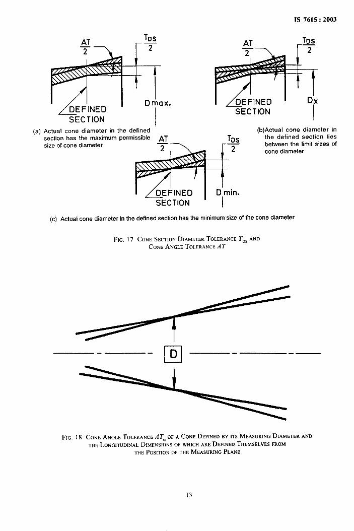
(a) Actual cone diameter in the definedsection has the maximum permissible ATsize of cone diameter 77
IS 7615:2003
ATT
SECTION
(b)Actual cone diameter in
TDs the defined section liesr= between the limit sizes of
f cone diameter
SECTION
(c) Actual cone diameter in the defined section has the minimumsize of the cone diameter
FIG. 17 CONESECTIONDIAMETERTOLERANCET~~ ANDCONEANGLETOLERANCEAT
c1-D .—
FIG. 18 CONEANGLETOLERANCEA Tu OFA CONEDEFINEDBY ITSMEASURINGDIAMETERANDTNELONGITUDINALDIMENSIONSOFWHICHAREDEFINEDTHEMSELVESFROM
THEPOSITIONOFTHEMEASURINGPLANE
13
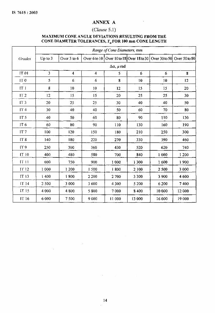
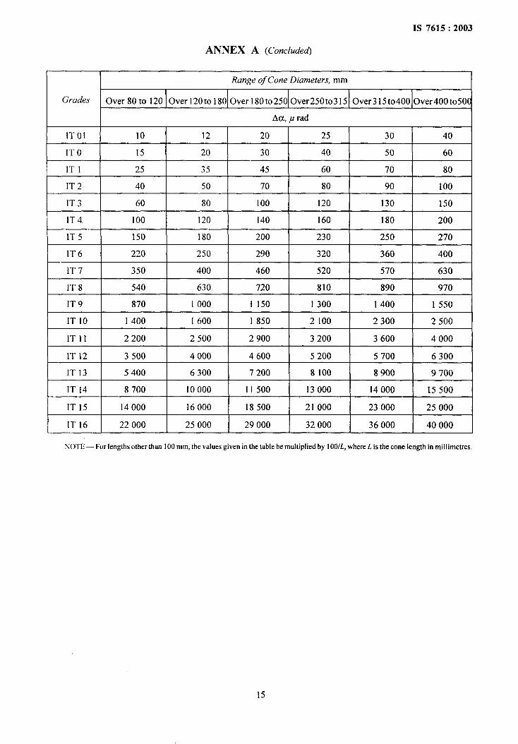
ANNEX A
(Clause 5.1)
MAXIMUM CONE ANGLE DEVIATIONS RESULTING FROM THECONE DIAMETER TOLERANCES, TDFOR 100 mm CONE LENGTH
Range of Cone Diameters, mm
Grades up to 3 Over 3 to 6 Over 6 to 10 Over 10to18 Over 18t030 Over 30t050 Over 50t080
I Aa, p rad IlTO1 3 4 4 5 6 6 8
IT O 5 6 6 8 10 10 12
IT I 8 10 10 12 15 15 20
IT 2 12 15 15 20 25 25 30
IT 3 20 25 25 30 40 40 50
IT 4 30 40 40 50 60 70 80
IT 5 40 50 60 80 90 110 130
IT 6 60 80 90 110 130 160 190
IT 7 100 120 150 180 210 250 300
IT 8 140 180 220 270 330 390 460
IT 9 250 300 360 430 520 620 740
ITIO 400 480 580 700 840 1000 1200
lTI1 600 750 900 1000 1300 1600 1900
IT 12 1000 1200 1500 1800 2100 2500 3000
IT 13 1400 1800 2200 2700 3300 3900 4600
IT 14 2500 3000 3600 4300 5200 6200 7400
IT15 4000 4800 5800 7000 8400 10000 12000
IT 16 6000 7500 9000 11000 13000 16000 19000
1S 7615:2003
ANNEX A (Concluded)
Range of Cone Diameters, mm
Grades Over 80 to 120 Over 120to 180 Over 180t0250 Over250t0315 Over315 to400 Over400t050C
Aa, p rad
lTO1 10 12 20 25 30 40
IT O 15 20 30 40 50 60
IT I 25 35 45 60 70 80
IT 2 40 50 70 80 90 100
IT 3 60 80 I00 120 130 150
IT 4 100 120 140 160 180 200
IT 5 150 180 200 230 250 270
IT 6 220 250 290 320 360 400
IT 7 350 400 460 520 570 630
IT 8 540 630 720 810 890 970
IT 9 870 1000 1150 1300 1400 1550
IT 10 1400 1600 1850 2100 2300 2500
ITll 2200 2500 2900 3200 3600 4000
IT 12 3500 4000 4600 5200 5700 6300
IT 13 5400 6300 7200 8100 8900 9700
IT 14 8700 10000 11500 13000 14000 15500
1T15 14000 16000 18500 21000 23000 25000
IT 16 22000 25000 29000 32000 36000 40000
NOTE — For lengthsother than 100 mm, thevaluesgiven in the table bemultiplied by 100/L, where L is the conelength in mill imetres.
w
Bureau of Indian Standards
BIS is a statutory institution established under the Bureau of Indian Standards Act, 1986 to promote harmoniousdevelopment of the activities of standardization, marking and quality certification of goods and attending toconnected matters in the country.
Copyright
BIS has the copyright of all its publications. No part of these publications may be reproduced in any formwithout the prior permission in writing of BIS. This does not preclude the free use, in the course of implementingthe standard, of necessary details, such as symbols and sizes, type or grade designations. Enquiries relating tocopyright be addressed t~ the Director (Publication), BIS.
Review of Indian Standards
Amendments are issued to standards as the need arises on the basis of comments. Standards are also reviewedperiodically; a standard along with amendments is reaffirmed when such review indicates that no changes areneeded; if the review indicates that changes are needed, it is taken up for revision. Users of Indian Standardsshould ascertain that they are in possession of the latest amendments or edition by referring to the latest issue of‘BIS Catalogue’ and ‘Standards: Monthly Additions’.
This Indian Standard has been developed from Dot: No. BP 20 (340).
Amendments Issued Since Publication
Amend No. Date of Issue Text Affected
BUREAU OF INDIAN STANDARDSHeadquarters:
Manak Bhavan, 9 Bahadur Shah Zafar Marg, New Delhi 110002 Telegrams: ManaksansthaTelephones: 23230131,23233375,2323 9402 (Common to all offices)
Regional Offices: Telephone
Central :
Eastern :
Northern :
Southern :
Western :
Branches :
Manak Bhavan, 9 Bahadur Shah Zafar Marg{
23237617NEW DELHI 110002 23233841
1/14 C.I.T. Scheme VII M, V.I.P. Road, Kankurgachi{
23378499,23378561KOLKATA 700054 23378626,23379120
SCO 335-336, Sector 34-A, CHANDIGARH 160022{
603843609285
C.I.T. Campus, IV Cross Road, CHENNAI 600113{
22541216,2254144222542519,22542315
Manakalaya, E9 MIDC, Marol, Andheri (East){
28329295,28327858MUMBAI 400093 28327891,28327892
AHMEDABAD. BANGALORE. BHOPAL. BHUBANESHWAR. COIMBATORE. FARIDABAD.GHAZIABAD. GUWAHATI. HYDERABAD. JAIPUR. KANPUR. LUCKNOW. NAGPUR.NALAGARH. PATNA. PUNE. RAJKOT. THIRUVANANTHAPURAM. VISAKHAPATNAM.
Printed at Simco Printing Press, Delhi