IS 7028-3 (2002): Performance Tests for Complete, Filled ...5 APPARATUS 5.1 Impact surface-which...
13
Disclosure to Promote the Right To Information Whereas the Parliament of India has set out to provide a practical regime of right to information for citizens to secure access to information under the control of public authorities, in order to promote transparency and accountability in the working of every public authority, and whereas the attached publication of the Bureau of Indian Standards is of particular interest to the public, particularly disadvantaged communities and those engaged in the pursuit of education and knowledge, the attached public safety standard is made available to promote the timely dissemination of this information in an accurate manner to the public. इंटरनेट मानक “!ान $ एक न’ भारत का +नम-ण” Satyanarayan Gangaram Pitroda “Invent a New India Using Knowledge” “प0रा1 को छोड न’ 5 तरफ” Jawaharlal Nehru “Step Out From the Old to the New” “जान1 का अ+धकार, जी1 का अ+धकार” Mazdoor Kisan Shakti Sangathan “The Right to Information, The Right to Live” “!ान एक ऐसा खजाना > जो कभी च0राया नहB जा सकता ह ै” Bhartṛhari—Nītiśatakam “Knowledge is such a treasure which cannot be stolen” IS 7028-3 (2002): Performance Tests for Complete, Filled Transport Packages, Part 3: Horizontal Impact Tests (Horizontal or Inclined Test; Pendulum Test) [TED 24: Transport Packages]
Transcript of IS 7028-3 (2002): Performance Tests for Complete, Filled ...5 APPARATUS 5.1 Impact surface-which...

Disclosure to Promote the Right To Information
Whereas the Parliament of India has set out to provide a practical regime of right to information for citizens to secure access to information under the control of public authorities, in order to promote transparency and accountability in the working of every public authority, and whereas the attached publication of the Bureau of Indian Standards is of particular interest to the public, particularly disadvantaged communities and those engaged in the pursuit of education and knowledge, the attached public safety standard is made available to promote the timely dissemination of this information in an accurate manner to the public.
इंटरनेट मानक
“!ान $ एक न' भारत का +नम-ण”Satyanarayan Gangaram Pitroda
“Invent a New India Using Knowledge”
“प0रा1 को छोड न' 5 तरफ”Jawaharlal Nehru
“Step Out From the Old to the New”
“जान1 का अ+धकार, जी1 का अ+धकार”Mazdoor Kisan Shakti Sangathan
“The Right to Information, The Right to Live”
“!ान एक ऐसा खजाना > जो कभी च0राया नहB जा सकता है”Bhartṛhari—Nītiśatakam
“Knowledge is such a treasure which cannot be stolen”
“Invent a New India Using Knowledge”
है”ह”ह
IS 7028-3 (2002): Performance Tests for Complete, FilledTransport Packages, Part 3: Horizontal Impact Tests(Horizontal or Inclined Test; Pendulum Test) [TED 24:Transport Packages]


i’,,,
$’
IS 7028 (Part 3) :2002
. ..—
m-3 M?rGrTi-m!-edkwl
(
Indian Standard
PERFORMANCE TESTS FOR COMPLETE,FILLED TRANSPORT PACKAGES
PART 3 HORIZONTAL IMPACT TESTS(HORIZONTAL OR INCLINED TEST, PENDULUM TEST)
(’Second Revision)
ICS 43.060.40
0 BIS 2002
BUREAU OF INDIAN STANDARDSMANAK BHAVAN, 9 BAHADUR SHAH ZAFAR MARG
NEW DELHI 110002
.
Fehruuty 2002 Price Group 4

Transport Packages and Packaging Codes Sectional Committee, TED 24.
FOREWORD
This Indian Standard (Part 3) (Second Revision) was adopted by the Bureau of Indian Standards, after the draftfinalized by Transport Packages and Packaging Codes Sectional Committee had been approved by TransportEngineering Division Council.
This Standard was first published in 1973. The second revision has been undertaken to bring it in line with1S0 2244:2000 ‘Packaging — Complete, tilled transport packages and unit loads — Horizontal impact tests’.issued by International Organization for Standardization (1S0).
In this revision the following technical changes have been incorporated:
a) Clauses on References and Terminology have been added, and
b) Figures pertaining to tolerances on the test specimen attitude for an impact on an edge or a corner havebeen added for clear illustration.
Packages intended for transport of goods are required to fulfill the primary function of physical protection to thecontents. The packages are transported normally by road, rail, sea and air, as also inland water-ways either byone or a combination of these modes. The nature of the hazards that are confronted during transport is widelyvarying depending upon the distribution system, handling methods and skills of staff employed. Performancetests are developed for complete, filled transport packages with a view to enabling one determine in advance asto how a package would fair in a given distribution system,
Packages in alI modes of transport are subjected to horizontal impact due to sudden change in velocity of thesystem. The impact may be between package to package, package to the wall of distribution system or amongthe contents within the package. The different momentum is imparted to the packages and its contents dependingon their bulk density.
The composition of the Committee responsible for the formulation of this standard is given in Annex A.

IS 7028 (Part 3):2002
Indian Standard
PERFORMANCE TESTS FOR COMPLETE,FILLED TRANSPORT PACKAGES
PART 3 HORIZONTAL IMPACT TESTS(HORIZONTAL OR INCLINED TEST, PENDULUM TEST)
(Second Revision)
1 SCOPE
This standard (Part 3) (Second Revision) specifiesmethods of horizontal impact testing (horizontal orinclined plane test and pendulum test) on a complete,tilled transport package or a unit load. The test maybe performed either as a single test to investigate theeffects of horizontal impact or as part of a sequence oftests designed to measure the ability of a package or aunit load to withstand a distribution system thatincludes a horizontal impact hazard.
2 REFERENCES
The following standards contain provisions whichthrough reference in this text, constitute provision ofthis standard. At the time of publication, the editionsindicated were valid. All standards are subject torevision, and parties to agreements based on thisstandard are encouraged to investigate the possibilityof applying the most recent editions of the standardsindicated below:
JS No. Title
7030:1988 Identification of parts for complete,filled transport packages when test-ing (/lrst revision)
7031:2001 Method of conditioning for testingof complete, tilled transport pack-ages (second revision)
3 TERMINOLOGY
For the purpose of this standard, the following termand definition shall apply.
3.1 Test Specimen
A complete, filled transport package or unit load.
4 PRINCIPLE
4.1 Applying a horizontal velocity to the test specimenand bringing it to a halt by impact with a verticalimpact surface. The atmospheric conditions, theimpact velocity and the attitude of the test specimenare predetermined. Particular conditions of impact maybe simulated by placing appropriately protiled insertsbetween the impact surface and the impacting face oredge of the test specimen.
5 APPARATUS
5.1 Impact surface-which should be either:
a) a plane inclined to the vertical at 10° + 1°(for the inclined plane test), or
b) a plane vertical to within 1°(for the horizontalor pendulum test).
5.1.1 The dimensions of the impact surface shall begreater than those of the impacting face, or selectedpart, of the test specimen.
5.1,2 The impact surface shall be suftlciently rigidnot to deflect more than 0.25 mm when a load of160 kg is applied anywhere on the surface.
5.1.3 In addition, the apparatus shall meet the require-ments and tolerances specified in 7.
5.2 Optional Interposed Hazards
They are to be used when it is required to concentratethe impact in a particular area of the test specimen.The dimensions, material and location of the inter-posed hazard shall be carefully specified.
Example
A steel beam with a length of 200 mm and a cross-section of(100 + 1) mm x (100* 1)mm with roundededges of radius (5 + 0.5) mm, placed centrally to theimpact surface (5.1).
5.3 Impact Apparatus
Types which may be used are described in 5.3.1; 5.3.2and 5.3.3.
5.3.1 Inclined Plane Tester — consist of the followingitems.
5.3.1.1 Two-rail steel track — inclined at 10° to thehorizontal.
The distance along the incline shall be graduated atintervals of 50 mm (see Fig. 1).
5.3.1.2 Rolling carriage — The surface frictionbetween the rolling carriage/dolly and the testspecimen shall be such that during movement from
1
IS 7028 (Part 3) :2002
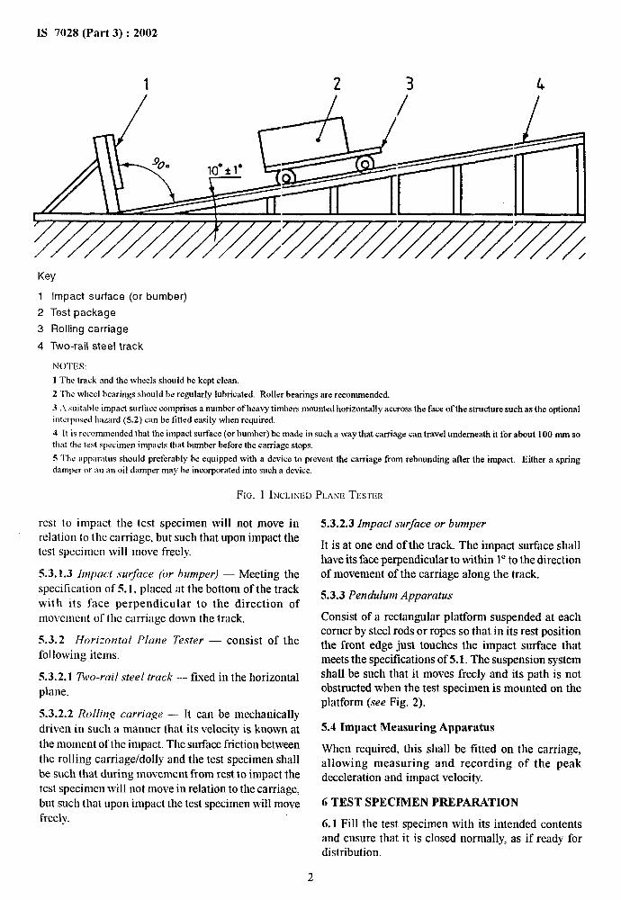
1 2 3 4
Key
1
2
3
4
Impact surface (or
Test package
Rolling carriage
Two-rail steel track
bumber)
NOTES:
1 The track and the wheels should be kept clean.
2 The wheel hearings should be regularly lubricated. RolIer bearings are recommended.
3 A suitable impact surface comprises a numberof heavy timbersmountedhorizontallyaccross the face of the structure such as the optionalinterposedImzard(5.2) can he fittedeasily whenrequired.
4 H is rccxmunendedthat the impact surface (or humber)be made in such a way that carriage can travel underneathit for about 100 mm sothat the test specimen impacts that bumber beforethe carriage stops.
5 “1’hcapparatus should preferably he equippedwith a device to prevent the carriage from rebounding after the impact. Either a springdamper or an an oil damper may be incorporated into such a device.
F1~. 1 INCLINEDPLANETESTER
rest to impact the test specimen will not move inrelation tot he carriage, but such that upon impact thetest specimen will move freely
5.3.1.3 Impact stir-ace (or bumper) — Meeting thespecification of 5.1, placed at the bottom of the trackwith its face perpendicular to the direction ofmovement of the carriage down the track.
5.3.2 [horizontal Plane Te.vter — consist of thefollowing items.
5.3.2.1 Two-rail steel track — fixed in the horizontalplane.
5.3.2.2 Rolling carriage –- H can be mechanicallydriven in such a manner that its velocity is known atthe moment of the impact. The surface friction betweenthe rolling carriage/dolly and the test specimen shallbe such tluat during movement from rest to impact thetest specimen will not move in relation to the carriage,but such that upon impact the test specimen will movefreely.
5.3.2.3 Impact surface or bumper
It is at one end of the track. The impact surface shallhave its face perpendicular to within 1°to the directionof movement of the carriage along the track.
5.3.3 Pendulum Apparatus
Consist of a rectangular platform suspended at eachcorner by steel rods or ropes so that in its rest positionthe front edge just touches the impact surface thatmeets the specifications of 5.1. The suspension systemshall be such that it moves freely and its path is notobstructed when the test specimen is mounted on theplatform (see Fig. 2).
5.4 Impact Measuring Apparatus
When required, this shall be fitted on the carriage,allowing measuring and recording of the peakdeceleration and impact velocity.
6 TEST SPECIMEN PREPARATION
6.1 Fill the test specimen with its intended contentsand ensure that it is closed normally, as if ready fordistribution.
2

.,.
IS 7028 (Part 3) :2002
\
\
+’J-
\.i
.
\
5==-’
\.
\ \
““r””–””lI&4423
!3
\‘k 3
/
Key
1 Steel rods or ropes
2 Impact surface
3 Test package
4 Rectangular platform
NOTE — For certain types oftest specimen, such as ‘carboys’, it may be sutilcientto suspend the test specimen from a single rod or rope. Inboth instances the suspension system shall not impart a rotary movement to the test specimen.
FIG. 2 PENOULUMAPPARATUS
NOTE --– Simulated or substituted contents may be used, oncondition that the dimensions and physical properties of suchcontents should be as close as possible to those of the intendedcontents. The ckrsure should still be m for distribution.
6.2 Conditioning
The test specimen shall be conditioned in accordancewith one of the conditions described in IS 7031.
7 PROCEDURE
7.1 General
7.1.1 Wherever possible the test shaIl be carried outin atmospheric conditions identical to those used forconditioning, and particularly where this is critical tothe materials or application of the test specimen. Inother circtunstances, the test shall be cartied out in
atmospheric conditions which approximate those usedfor conditioning as closely as is practicable.
7.1.2 The velocity at impact shall be within * 5 percentof the predetermined impact velocity.
7.1.3 When the impact is on a face, the test specimenshall strike the impact surface so that the anglebetween the face and the plane of the impact surfaceis less than 2°.
7.1.4 When the impact is on an edge, the attitude ofthe test specimen at impact shall be such that the anglebetween the edge and the plane of the impact surfaceis less than 2° and such that the angle ~ between oneadjacent face and the impact surface is within * 5° or10 percent of the predetermined angle, whichever isthe greater (see Fig. 3).
3

IS 7028 (Part 3):2002
al
T
-.
[
—.
a,, Cl*:<2°
B,, ~,; * 5°0r*10 percent
a) Impact on a vertical edge
i
.-
f \
az
lt-
[
—.
I
II
- -“t-.—.—.—._-.I I
b) Impact on a horizontal edge
NOTE — Shown for the inclined plane test. The same tolerances apply to the horizontal plane and pendulum test.
FIG. 3 TOLERANCES ON THE TEST SPECIMEN ATTITUDE FORAN IMPACTPN AN EDGE
7.1.5 When the impact is on a corner, the test specimenshall strike the impact surface so that the angle ~between any face adjoining the tested corner and theimpact “surface is within + 5° or 10 percent ofthe predetermined angle, whichever is the greater(see Fig. 4).
NOTE — Shown for the inclined plane test. The same tolerances
apply to the horizontal planeandpendulumtests.
7.2 Inclined Plane Test
7.2.1 Place the test specimen on the carriage in anattitude that will ensure that it strikes the impactsurface (5.3. 1.3) in the desired position (7.1).
7.2.2 Whenever possible the test specimen shall notproject beyond the edges of the carriage. Raise thecarriage to that height, up the incline (5.3.1.1), whichcorresponds with the desired impact velocity, thenrelease it.
7.3 Horizontal Plane Test
7.3.1 Place the test specimen on the carriage (5.3.2.2)as described in 7.1.
7.3.2 Set the carriage in motion along the steel trackat a velocity predetermined to give the desired impactvelocity on the impact surface (5.3.2.3).
7.4 Pendulum Test
7.4.1 Place the test specimen on the rectangularplatform (5.3.3) as described in 7.1 so that theimpacting face or edge just touches the impact surface.
7.4.2 Raise the pendulum by pulling out the platformto the distance from the impact surface appropriate tothe velocity required, then release it.
8 TEST REPORT
The test report shall include:
a) a reference to this standard;
4

.. ----
b)
c)
d)
e)
0
~)
h)
j)
name and address of testing laboratory and k)the name and address of customer;
unique identification of the report;
date of receipt of the test specimens and the m)
date(s) of performance of the test;
mime, title and signature of persons acceptingtest responsibility for the test report;
statement to the effect that the results relateonly to the specimens tested; n)
a statement that the report shall not bereproduced except in full without the written P)
approval of the testing laboratory;
the number of replicate test specimens tested,
a full description, including dimensions, q)
structural and material specifications of thetest specimen and its fittings, cushioning, r)
blocking, closure and reinforcing arrange- s)
ments, gross mass of the test specimen andmass of the contents in kilograms; and t)
IS 7028 (Part 3) :2002
a description of the contents and if simulatedor substituted contents were used, fill detailsshall be given;
relative humidity, the temperature and timeof conditioning the temperature and relativehumidity of the test area at the time of testand whether these values comply with therequirements of IS 7031.
velocity at impact and if required, the peakdeclaration.
attitudes in which the test specimen wastested, using the method of identification,given in IS 7030;
position and description of any interposedhazard if used:
type of apparatus used;
any deviation from the test method describedin this standard;
a record of the result, including any observa-tions which assist in the correct interpretationof the results.
— I.—
~,, ~,: + 5° or * 10 percent
NOTE -— Shown forthe inclinedplanetest. Thesametolerancesapplyto the horizontalplane andpendulumtest.
Ftci. 4 TOLERANCESON THETEST SPECIMBNATTITUDEFORAN IMPACTON A CORNER

1S 7028 (Part 3) :2002
ANNEX A
(Foreword)
COMMITTEE COMPOSITION
Transport Packages and Packaging Codes Sectional Committee, TED 24
Organization
Indian Institute of Packaging, Mumbai
Advance Packaging Pvt Ltd, Mumbai
Association of Small Tool Mfis, Chennai
Association ot3tate Road Transport Undertaldng, New Delhi
Bayer India Ltd, Mumbai
Bharat Electronics Ltd, Bangalore
BHEL, Hyderabad
BASF India Ltd, Mumbai
Balmer Lawrie Van Leer Ltd, New Mumbai
Containers Corp of India Ltd, New Delhi
Department of Explosives, Nagpur
Department ofTelecommunication, New Delhi
Dkectorate of PPQ & S, Faridabad
Dimple Drums & Barrels Ltd, Mumbai
Electronics Corp of India Ltd, Hyderabad
Federation ofCorrugated Box Manufacturers ofhrdia, Mumbai
Fibre Foils Ltd, Mumbai
Guardian Plasticots Ltd, Mumbai
Grindwell Norton Ltd, Mumbai
Gujarat Ambuja Cement Ltd, Mumbai
Indian Ahrminium Co Ltd, Mumbai
Indian Federation ofTransport Operators, Mumbai
Indian Institute of Packaging, Mumbai
India Foils Ltd, Kolkata
lTC Ltd, Kolkata
ITI Ltd, Cionda (U.P)
Jumbo Bag Ltd, Chennai
Larsen & ‘rourbo Ltd, Mumbai
Representative(s)
SrrRIP. V. NARAYANAN(Chairman)
SHRIDAMODARSow
SHRIS. RAJAODPALAN
SHRIM. S. BALACHANDSAN(Alternate)
DIRECTOR(ENGG)
ASSISTANTDIRECTOR(TECHNICAL)(Alternate)
DRN. K. PONKSHE
DR A. S. NADKARNI(Alternate)
Smu S. A.RAo
.%0 RAWCHANDESr
SHSUM. S. SrNmvAD (Alternate)
SHRIB. JOSHI
sHRr‘MITSHAH
SNRIS. C. GUPTA
SW A. S. GHOSHAL
SHFOG. M. SARMA(Alternate)
ASSISTANTDIRECTORGENERAL(SL)
ASSISTANTDIWYOR GENERAL(ST) (Alternate)
SHRIV. C. BHARCAVA
SrnuS. H. GHOSE(Alternate)
$kru RAJESHH. KAPAOL4
ME+G. V. kADAYAL
SHSIP. P. SrNcar(Ahernate)
SHRIA. K. GOEL
SHRIA. L. ANNAMALAI(Alfernafe)
SHRIGOPiNATHA. %SARMA
SmuG. R. RAMACHANDRAN
SttruAsras ROY(Alternate)
SaRI P. K. GUJRAL
SHRIV. J.BARDANOKAR(Alfemafe)
SHRIC. M. DORM
SHRIK. M. KAVADIA(Alternate)
!%w M. S. VERMA
Smu B. BALAGOPAL(Alternafe)
Mu T. M. OBHAN
SsmuHARIORATSrNcaIKomJ (Alternaie)
DRN. G. MoKAsrD
,%rruB. MALLICK
SHRIM. K. CmKRAOORTV(Alternate)
DRP. P. SrNoH
SHRIC. T. DHRUVAKRISHNAN(Alternate)
SHRIA. K. GOEL
SHRIG. SUDHAKAR
SHRIH. H. Dosr+r
J
Smu P. N. Dr!s.M(Alferrrate)
(Continued on Page 7)
6

(COntlWfWij’0117Pa,qe 6)
Or~mfizution
Lemuir Packers
klioistry of Deticocc, Dkectorate o i’Standardization, DRDO, Barrgalorc
Paper Products Ltd, New Deibi
Ranbaxy Lahoratnries Ltd, Gorgaon
Rcsearcb Designs& Standards Organization, Laclinow
Tbc Shipping Corporation of India, Mumbai
The Supreme lncls Ltd, Mumbai
WIPR() Ltd, Mombai
BIS Directorate Gcoeral
IS 7028 (Part 3) :2002
Representative(s)
DLREmOK
SHRIS. GURUPRAS~O
SHRiANtLTALWAR
SHRiA. K. BHATT(Alfernute I)
SHRIH. L. CHOPRA(Aherna/e 11)
ASSISTANTDRELTOR
JoaNTDIRECTORSTANDAROS/CARRtAGEI
ASSISTAmDESIGNENGtNEER/CARRtA~EI (.4kwrate)
GENERALMANAGER
TECHNtCALSERVICES(Akernate)
%0 V. SHANRAR
SHRLMUKESHSHAH(Alternate)
sHRrP. s.PAISmu A. R. GULATt,DIRECTOR& HEAD(Transport Engg)
[Representing Director General @x-oflcio Member)]
Member SecretarySHRLP. K. SHARMA
Joint Director (Transport Engg), BIS
Bureau of Indian Standards
—-—. .—
—
BIS is a statutory institution established under the Bureau of Zndian Standards Act, 1986 to promoteharmonious development of the activities of standardization, marking and quality certification of goodsand attending to connected matters in the country.
Copyright
BIS has the copyright of all its publications. No part of these publications may be reproduced in any formwithout the prior permission in writing of BIS. This does not preclude the free use, in the course ofimplementing the standard, of necessary details, such as symbols and sizes, type or grade designations.Enquiries relating to copyright be addressed to the Director (Publications), B1S.
Review of Indian Standards
Amendments are issued to standards as the need arises on the basis of comments. Standards are also reviewed
periodically: a standard along with amendments is reaffirmed when such review indicates that no changes areneeded; if the review indicates that changes are needed, it is taken up for revision. Users of Indian Standardsshould ascertain that they are in possession of the latest amendments or edition by referring to the latest issue of‘BIS Cacalogue’ and ‘Standards: Monthly Additions’.
This Indian Standard has been developed from Doc : No. TED 24 (324).
Amendments Issued Since Publication
Amend No. Date of Issue Text Affected
BUREAU OF INDIAN STANDARDS
Headquarters :
Manak Bhavan, 9 Bahadur Shah Zafar Marg, New Delhi 110002 Telegrams : Manaksanstha
Telephones :3230131, 3233375, 3239402 (Common to all offices)
Regional Offices : Telephone
Central :
Eastern :
Northern :
Southern :
Western
Manak Bhavan, 9 Bahadur Shah Zafar Marg
{
3237617
NEW DELHI 110002 3233841
1/14 C.I.T. Scheme VII M, V. I. P. Road, Kankurgachi
{
3378499, 3378561KOLKATA 700054 3378626, 33791 20
SCO 335-336, Sector 34-A, CHANDIGARH 160022
{
603843602025
C.1.T. Campus, IV Cross Road, CHENNAI 600113
{
2541216,25414422542519,2541315
Manakalaya, E9 MIDC, Marol, Andheri (East) ~83292 95,8327858MUMBAi 400093 ~8327891,8327892
Branches : Al-I ME DABAD. BAN GALORE. BHOPAL. BH[JBANESHWAR. COIMBATORE.FAR IDABAD. GHAZIABAD. GUWAHATI. HYDERABAD. JAIPUR. KANPUR.LUCKNOW. NAGPUR. NALAGARH. PATNA. PUNE. RAJKOT. THIRUVANANTHAPURAM.
Printedat Prlllhtt[{Jtis?tPIKSS, New Delh~2