IS 5700 (1977): Cinematograph screens - Public.Resource.OrgIS : 5700 - 1977 3.7 Reflectance and...
19
Disclosure to Promote the Right To Information Whereas the Parliament of India has set out to provide a practical regime of right to information for citizens to secure access to information under the control of public authorities, in order to promote transparency and accountability in the working of every public authority, and whereas the attached publication of the Bureau of Indian Standards is of particular interest to the public, particularly disadvantaged communities and those engaged in the pursuit of education and knowledge, the attached public safety standard is made available to promote the timely dissemination of this information in an accurate manner to the public. इंटरनेट मानक “!ान $ एक न’ भारत का +नम-ण” Satyanarayan Gangaram Pitroda “Invent a New India Using Knowledge” “प0रा1 को छोड न’ 5 तरफ” Jawaharlal Nehru “Step Out From the Old to the New” “जान1 का अ+धकार, जी1 का अ+धकार” Mazdoor Kisan Shakti Sangathan “The Right to Information, The Right to Live” “!ान एक ऐसा खजाना > जो कभी च0राया नहB जा सकता ह ै” Bhartṛhari—Nītiśatakam “Knowledge is such a treasure which cannot be stolen” IS 5700 (1977): Cinematograph screens [MED 32: Photographic Equipment]
Transcript of IS 5700 (1977): Cinematograph screens - Public.Resource.OrgIS : 5700 - 1977 3.7 Reflectance and...

Disclosure to Promote the Right To Information
Whereas the Parliament of India has set out to provide a practical regime of right to information for citizens to secure access to information under the control of public authorities, in order to promote transparency and accountability in the working of every public authority, and whereas the attached publication of the Bureau of Indian Standards is of particular interest to the public, particularly disadvantaged communities and those engaged in the pursuit of education and knowledge, the attached public safety standard is made available to promote the timely dissemination of this information in an accurate manner to the public.
इंटरनेट मानक
“!ान $ एक न' भारत का +नम-ण”Satyanarayan Gangaram Pitroda
“Invent a New India Using Knowledge”
“प0रा1 को छोड न' 5 तरफ”Jawaharlal Nehru
“Step Out From the Old to the New”
“जान1 का अ+धकार, जी1 का अ+धकार”Mazdoor Kisan Shakti Sangathan
“The Right to Information, The Right to Live”
“!ान एक ऐसा खजाना > जो कभी च0राया नहB जा सकता है”Bhartṛhari—Nītiśatakam
“Knowledge is such a treasure which cannot be stolen”
“Invent a New India Using Knowledge”
है”ह”ह
IS 5700 (1977): Cinematograph screens [MED 32: PhotographicEquipment]


IS : 5700 - 1977
lndlan Standard SPECIFICATION FOR
CINEMATOGRAPH SCREENS
( First Revision)
Cinematographic Equipment Sectional Committee, ETDC 47
Chairman
SHRI B.A. MISTRY
Pearl Mansion, Queens Road, Bombay 400020
Members Representing
SHRI S. N. AQARWAL SHRI S. P. AGARWAL (Alternate)
Cinecita Private Limited, Bombay
SHRI N. P. BHATTACHARYA Department of Teaching Aids, National Council of
DR A. F. CHHAPCAR Educational Research and Training, New Delhi
National Physical Laboratory ( Acoustics Division ) ( CSIR ), New Delhi
SHRI Y. R. CHAUHAN Cine Sales Corporation, Delhi SHRI R. S. CHAUHAN ( AIternate)
SHRI K. RAJAGOPAL CHETW SHRI K. N. GNANAPRAQASAM
Devi Cine Projector Mfg Co, Madras
( Alternate ) SHRI BHUPON GHOSH
SHRI MANNA LADIA ( Alternate ) Cine Mechanical Works, Calcutta
SARI HARSH VARDHAN Film and TV Institute of India I Ministrv of Infor-
SHRI S. B. THAKAR ( Alternate 1 mation & Broadcasting ), Puhe ’
’ SHRI R. V. KELKAR SHRI S. L. NAIK ( Alternote )
’ Photophone Ltd, Bombay
MAJ S. P. MURGAI SHRI V. S. MURTHY ( Alternate )
Ministry of Defence ( DGI )
SHRI K. N. RAMAswAhW Dire;or$;e,cneral of Technical Development, e
SIIRI BALRAJ BHANOT ( Alternate ) SIXRI RAM PRASAD National Phvsical Laboratory ( Optics Division )
SURI M. SANKARALIN~AM ( CSIR ), New Delhi
Directorate General of New Delhi
Supplies and Disposals,
SHRI G. R. BHATIA ( Alternate )
( Continued onPage 2 )
Q Copyright 1978 INDIAN STANDARDS INSTITUTION
This publication is protected under the Indian Copyright Act (XIV of 1957) and reproduction in whole or in part by any meansexcept with written permission of the publisher shall be deemed to be an infringement of copyright under the said Act.

- ---------
1s : 5700 - 1977
( Continued from page 1 )
Members Representing
DR P. R. K. SARMA Hindustan Photo Films Mfg Co Ltd, Ootacamund SHRI A. KRISHNAMURTHY ( Alternate )
SHRI G. G. VASWANI Films Division (Ministry of Information & Broad- casting ), Bombay
SHRI S. P. SACHDEV, Director General, IS1 ( Ex-o@cio Member) Director ( Elec tech )
Secretary
SHRI JAGDISH CHANDRA
Assistant Director ( Elec tech ), IS1

IS : 5700 - 1977
Indian Standard SPECIFICATION FOR
CINEMATOGRAPH SCREENS
(First Revision)
0. FOREWORD
0.1 This Indian Standard ( First Revision) was adopted by the Indian Standards Institution on 8 November 1977, after the draft finalized by the Cinematographic Equipment Sectional Committee had been approved by the Electrotechnical Division Council. 0.2 This standard was first published in 1970 and covered only methods of tests to determine the characteristics of cinematograph screens. The revision of this standard has been undertaken with a view to up-date its contents and make it a complete specification for cinematograph screens. 0.3 This standard is intended to deal with screens commonly used for cinematograph purposes. The surface of matt screens is invariably smooth and white, and the reflectance characteristics follow the cosine law. With the advent of wide screen techniques, it became necessary to devise screen surfaces that gives greater luminance over a limited forward sector than was possible with matt screens. Such screens are known as directional, and their improved reflectance over the forward sector is commonly known as their gain. The gain is achieved by applying parti- cles of glass, metallic paint or other compounds to the screen surface.
0.3.1 Although very few cinemas now use rear projection systems, it has nevertheless been considered desirable to include translucent screens in this standard. 0.4 In some small cinemas it may be desirable to install screens with small perforations, or to install screens without perforations; in such cases it is the responsibility of the purchaser to state his requirements. Simi- larly, in a few cases screens are not permanently installed but are flown or carried on rollers, and it is the responsibility of the purchaser to state his fixing requirements. Standardization of dimensions and fixing require- ments for portable screens are under consideration. 0.5 In preparing this standard assistance has been derived from BS : 5382-1976 Specification for cinematograph screens, issued by British Standards Institution. 0.6 For the purpose of deciding whether a particular requirement of this standard is complied with, the final value, observed or calculated, expressing the result of a test or analysis, shall be rounded off in
3
IS 2 5700 - 1977
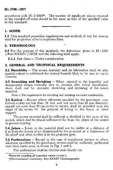
accordance with IS : 2-1960*. The number of significant places retained in the rounded off value should be the same as that of the specified value in this standard.
1. SCOPE
1.1 This standard prescribes requirements and methods of test for screens used for projection of motion-picture films.
2. TERMINOLOGY *
2.1 For the purpose of this standard, the definitions given in IS : 1885 ( Part XXXIV)-1972-J and the following shall apply.
2.1.1 Fair Curve - Under consideration.
3. GENERAL AND TECHNICAL REQUIREMENTS
3.1 Durability-The screen material and its fabrication shall be ade- quately robust to withstand the normal hazards likely to be met in USC in cinemas.
3.2 Stretching and Shrinking - When exposed to the humidity and temperature ranges normally met in cinemas after initial installation, there shall not be excessive stretching and shrinking of the screen material.
NOTE -The requirements for stretching and shrinking are under consideration.
3.3 Eyelets - Except where otherwise specified by the purchaser, non- ferrous eyelets not less than 12 mm and not more than 20 mm diameter, spaced not more than 30 cm centre to centre, shall be provided near the edges of the screen for the purpose of lacing to the frame or other support.
The screen material shall be stiffened or doubled in the area of the eyelets, which shall be placed sufficiently far from the edges of the screen to prevent tearing.
3.4 Joints --Joints in the material shall not be visible at a distance of 8 m from the screen when illuminated by the projector at a luminance of 50 cd/m2 and when no film is in the projector gate.
3.5 Perforations -Except in the case of translucent screens or where otherwise specified by the purchaser, screens shall be uniformly perforated over their entire area, as shown in Fig. 1 and 2.
The perforations shall be circular and cleanly cut.
*Rules for rounding off numerical values ( reuised ).
tElectrotechnica1 vocabulary: Part XXXIV Cinematography.
4

IS : 5700 - 1977
HORIZONTAL ROWS 9mm PITCH
e 0 0 a l 0
0 l 0 0 0
0 0 0 0 0 0
0 0 0 0 0
o- 0 0 0 0 0
0 0 0 0 0
o- 0 0 0 0 0
0 0 0 0 0
0 0 0 0 0 0
0 0 0 0 0
0 0 0 0 0 0
/---
Perforations 1.5 mm dia
FIG. 1 LARGE PERFORATIONS
l e 0 e e e l l e l l e 0 l l
-0-e 0 l l l l 0 e l l l l e 0
4eeeeeeo/ l l l l l 0 l
l l l l l l l l l l l l l l l
l l l l l l l l 0 l l l l l l
l l l l e l l l l eeeeoe
0 l l l 0 l
I I
HOi&iihOWS 6mm PITCH
Perforations 1.1 mm dia
FIG. 2 SMALL PERFORATIONS
3.6 Attenuation of Sound (Not Applicable to Unperforated Screens) -Attenuation of sound pressure due to the presence of a perforated screen in front of a loudspeaker shall not exceed 3 dB at 6 kHz and 6 dB at 12 kHz, compared with the attenuation of the sound pressure at 500 Hz, measured by the method given in 5.1.
The sound for this purpose shall be of sine-wave form of constant amplitude.
5

IS : 5700 - 1977
3.7 Reflectance and Transmittance of Light
3.7.1 The reflectance factor of a matt or directional screen, measured in accordance with the method described in 5.2, shall be within f5 percent of the factor specified by the purchaser.
3.7.2 The transmitance factor of a translucent screen measured in accor- dance with the method described in 5.3 shall be within rf5 percent of the factor specified by the purchaser.
3.8 Gain - The specified gain of a directional screen shall be the ratio of the luminance produced by a projected beam of white light falling normally upon a surface coated according to IS : 2407-l 963* and the same projected beam falling normally upon the screen surface, the reflect- ed light from which is being measured at a horizontal angle of 5” from the normal to the screen surface.
In the case of a screen having a lenticulated surface the reflected light shall be measured at both a horizontal and vertical angle of 5” from the normal to the screen surface, and the two ratios shall be specified separately.
3.9 Colour of Transmitted or Reflected Light -The material of which a translucent screen is made, or the surface of a reflecting screen, shall not change the tone of any colour passing through or projected upon it.
Any change of luminance apparent to an observer compared with the same colours projected on a surface coated according to IS : 2407- 1963*, shall be equivalent to the introduction or removai of a neutral gray filter in the projected light beam.
3.10 Flammability- The finished screen materials shall be self- extinguishing.
NOTE -Attention is drawn to the necessity for the flammability ‘characteristics of the screen not to be impaired by any subsequent resurfacing treatment.
4. MARKING
4.1 The screens shall be attached with a label containing the following information:
a) Name of manufacturer and/or supplier, b) Date of manufacture, c) Overall size, and d) Country of manufacture.
*Specification for photometric integrators.
6

IS : 5700 - 1977
4.1.1 The screens may also be marked with the IS1 Certification Mark.
NOTE - The use of the IS1 Certification Mark is governed by the provisions of the Indian Standards Institution ( Certification Marks ) Act and the Rules and Regulations made thereunder. The IS1 Mark on products covered by an Indian Standard conveys the assurance that they have been produced to comply with the requirements of that standard under a well-defined system of inspection, testing and quality control which is devised and supervised by IS1 and operated by the producer. IS1 marked products are also continuously checked by IS1 for conformity to that standard as a further safe- guard. Details of conditions under which a licence for the use of the IS1 Certification Mark may be granted to manufacturers or processors, may be obtained from the Indian Standards Institution.
5. TESTS
5.0 For the purpose of this standard, all tests shall be considered as type tests.
5.1 Test for Measurement of Attenuation of Sound
5.1.1 A@aratus Required
a) A signal generator giving a sine-wave output over a frequency range of not less than 500 Hz to 12 kHz.
b) An amplifier.
c) A wattmeter to measure the input to a speaker.
d) A pressure type speaker having a mouth diameter not less than. 76 mm or more than 152 mm.
e) A sound level meter complying with IS : 3932-l 966*.
NOTE-Any other suitable set up capable of measuring the transmission loss may be used.
5.1.2 Procedure - Suitably mount the speaker l-25 m above the floor with its axis arranged horizontally.
Place the sound level meter with its microphone concentric with the axis of the speaker and 2 m distant. Calibrate both the microphone and sound level meter to provide a flat response curve and apply the correction factors to the measurements.
Connect and arrange the apparatus as shown in Fig. 3.
Inject sine-wave signals of constant level into the speaker at the preferred frequencies in the range 500 Hz to 12 kHz, and record the readings of the wattmeter and sound level meter.
Stretch the screen under test which is to be not less than 2 m x 2 m, on a suitable frame and @ace it vertically and symetrically 150 mm in front of the mouth of the speaker.
*Specification for sound level meters for general purpose use.
7

IS : 5700 - 1977
I WATTMETER
fEN UNDER TEST
- MICROPHONE
FLOOR
FIG, 3 ARRANGEMENT OF APPARATUS FOR MEASURING ATTENUATION OF SOUND
Irrject signals of the same power and frequency into the speaker and record the readings of the wattmeter and sound level meter.
The attenuation of sound due to the presence of the screen is the difference between the respective readings of the sound level meter. These differences when plotted on a graph are to produce a fair curve.
5.2 Test for Measuring Reflectance Gain
5.2.1 Test Samble - The sample material is to be not less than 600 mm2.
5.2.2 Abparatus
a) A room with dark, non-reflecting surfaces. b) A source of substantially white light, suitably enclosed by an
opaque casing and provided with a lens of appropriate focal length. For this purpose a still prqjector or spot light may be used.
c) A metal or wooden frame upon which the test sample is stretched. d) A surface coated according to IS : 2407-1963*
NOTE - A sheet of clean white blotting paper may be substituted in which case its reflectance is taken as 80 percent.
e) A photometer having an acceptance angle not greater than 2” and having a spectral sensitivity of a standard observer as adopted by the International Commission on Illumination, 1939, and formally approved by the International Committee for Weights and Measures in 1933.
*Specification for photometric integrators.
8

IS : 5700 - 1977
5.2.3 Procedure - Set up the frame and test sample in a vertical position so that the reflecting surface of the sample faces the projector.
Position the projector so that the optical axis of the lens is normal, both in horizontal and vertical planes, to the centre of the test sample and produces a circle of light approximately 500 mm in diameter.
Place one surface as described in 5.2.2 (d) centrally and parallel to the surface of the test sample.
With the room in darkness and the projector light switched on, measure the luminance ( !_r ) at the centre of the comparison surface from a position in the same horizontal plane as the centre of the sample but at an horizontal angle of 5” from the normal of the screen surface (see Fig. 4).
Remove the comparison surface and measure the luminance ( L2 ) at the centre of the test sample from the same position.
The reflectance gain of the sample is
+-X 100 percent 1
Where a polar curve of the reflectance gain of a screen is required, it is to be plotted from measurements taken at a constant distance from the centre of the screen at intervals of 5” or 10” in the range 5” to 55” on either side of the normal to the screen.
REFLECTING SURFACE OF TEST SAMPLE
/
METER FOR MEASURING L1 AND L2
FIG. 4 ARRANGEMENT FOR MEASURING REFLECTANCE GAIN
5.2.4 Lenticulated Surfaces - Where the surface of the test sample is lenticulated, the procedure in 5.2.3 should be adopted for determining the horizontal gain, and the polar curve in the horizontal plane.
Additionally, take similar measurements in the vertical plane for determining the vertical gain and the polar curve in the vertical plane, but in the range 5” to 20”.
9

IS : 5700 - 1977
5.3 Test for Measuring Transmission Factor of Translucent Screens
5.3.1 fist Sample -The sample material is to be not less than 600 mma.
5.3.2 A@aratus - The apparatus required for the test is as listed for the measurement of reflectance gain ( see 5.2.2 ).
5.3.3 Procedure - Set up the frame and test sample in a vertical posi- tion so that the ‘ non-viewing ’ surface of the sample faces the projector. Position the projector so that the optical axis of the lens is normal, both in the horizontal and vertical planes, to the centre of the test sample and produces a circle of light approximately 500 mm in diameter.
Place one surface coated according to IS : 2407-1963* centrally and parallel to the surface of the test sample.
With the room in darkness, the projector light switched on, measure the luminance ( L3) at the centre of the comparison surface from a posi- tion as near as possible normal to that surface.
Remove the surface for comparison and measure the luminance ( Lp) at the centre of the test sample on its ‘ viewing surface ’ from a posi- tion normal to that of the surface ( see Fig. 5 ).
The transmission factor of the sample is
-+-x 100 percent a
5.4 Test for Flammability
5.4.1 Form of Test Specimen -- The specimen shall be 550 mm long and 35 mm wide cut from the sheet under test. The thickness of the specimen shall be the thickness of the sheet. The surfaces shall be clean and dry.
NON-VIEWING SURFACE
Ov PROJECTOR
~z=_z%cIe:
PHOTOMETER FOR MEASURING C,
FIG. 5 ARRANGEMENT FOR MEASURING
,,’ PHOTO - METER FOR MEASURING
L3
TRANSMISSION FACTOR
*Specification for photometric integrators.
10

IS : 5700 - 1977
5.4.2 Number of Test S’ecimens - Six specimens shall be used.
5.4.3 A@aratus - Fig. 6.
A general arrangement of the apparatus is shown in The apparatus shall consist of two parallel semicircular supports,
each L-shaped in cross section, curved to a radius of 178 mm, spaced apart at a distance suitable for supporting the test specimen within the angles, and standing on a baseplate. The two supports shall be made of brass about I.3 mm thick, and shall be spaced so that their inner edges are 254 -+ 0.8 mm apart, by means of wire spacers shaped as shown in Fig. 7.
The test specimen shall be held in position over the supports by two strips of spring steel, 4.8 mm wide and 0.13 mm thick each of which is riveted at one end to a hinge as shown in Fig. 8 ( section of hinge ). The other ends of the two steel strips shall be connected, at the appropriate distance apart, by a thin steel cross-bar as shown in Fig. 9.
Means shall be provided for securing the cross-bar in position, under spring tension, during the test as shown in Fig. 9.
At the end where the flame is applied to the specimen there shall be a flat metal platform between the supports, on which a small copper trough may be placed. The upper surface of the platform shall be 12.7 mm below the ( start ’ mark as shown in Fig. 8 ( end elevation ). The copper trough shall have the form and dimensions shown in Fig. 7.
SUPPORTS --7
SCA ^_
see Fig. 9
358 _--LI-_L--4
All dimensions in m illim etres.
h. 6 GENERAL ARRANQEMENT OF APPARATUS FOR FLAMMABILITY TEST
11

IS : 5700 - 1977
0.9 THICK (20 SWGI
COPPER TROUGH
Scale riveted to angle brackets on (L IOVOI
STEEL STRIPS
SECTION THROUGH SUPPORTS
All dimensions in millimetres.
Fro. 7 DETAILS OF COPPER TROUGH, WIRE SPACER AND SUPPORTS FOR
FLAMMABILITY TEST
SUPPORT FOR’
Steel strips hinged back for insertion
SCALE, I
SECTION AA HINGE OMITTED
SECTION OF HINGE
A 7
j
=p _- -_
3 t i --- -__ --- ___.
I t -I c, ----
A--j END ELEVATION
All dimensions in millimetres.
FIG. 8 DETAILS OF RIGHT-HAND END FOR FLAMMABILITY TEST

G CROSS-BAR
SECTION A A END ELEVATlOb
IS : 5700 - 1977
SCALE GRADUATED IN 5mm DIVISIONS
BASE PLATE e-
VIEW SHOWING DETAIL OF SPRING hINGING
All dimensions in millimetres.
FIG. 9 DETAILS OF LEFT-HAND END FOR FLAMMABILITY TEST
One of the semicircular supports shall be calibrated in 5 mm inter- vals from the ‘ start ’ mark for a distance of 530 mm around its perimeter. The whole apparatus shall be protected from draughts by. being screened on three sides with a screen having vertical panel, approximately 460 mm high.
5.4.4 Procedure -The test specimen shall be placed in the channel formed bv the two semicircular supports with one of its ends in line with the ‘ start” mark. The steel strips shall be drawn over and secured by the springs provided, thus holding the specimen firmly along each edge with a 25.4 mm wide centre portion in free air.
The copper trough shall be placed on the platform provided, cen- trally below the end of the test specimen and 0.1 ml of absolute alcohol ( ethanol) placed in it and ignited.
After burning has ceased the distance from the ‘ start ’ mark over which the test specimen is burned shall be noted. Where this distance appears to be indefinite the test specimen shall be folded along its length
13

IS : 5700 - 1977
and the distance of travel of the flame taken to be that distance at which the charred front falls away.
If the faces of the sheet differ then three test specimens shall be tested with one face outwards and three with the other face outwards.
The degree of flammability of the material shall he reported as the average of the test results obtained on the test specimens and shall be calculated to the nearest 3 mm.
5.4.5 Report - The report shall state: a) the degree of flammability in mm, 1,) the individual test results, and c) the conditioning, if any, of the test specimens.
14