IS 12813 (1989): Method of analysis of hydraulic cement by ... · With the advent of large scale...
16
Disclosure to Promote the Right To Information Whereas the Parliament of India has set out to provide a practical regime of right to information for citizens to secure access to information under the control of public authorities, in order to promote transparency and accountability in the working of every public authority, and whereas the attached publication of the Bureau of Indian Standards is of particular interest to the public, particularly disadvantaged communities and those engaged in the pursuit of education and knowledge, the attached public safety standard is made available to promote the timely dissemination of this information in an accurate manner to the public. इंटरनेट मानक “!ान $ एक न’ भारत का +नम-ण” Satyanarayan Gangaram Pitroda “Invent a New India Using Knowledge” “प0रा1 को छोड न’ 5 तरफ” Jawaharlal Nehru “Step Out From the Old to the New” “जान1 का अ+धकार, जी1 का अ+धकार” Mazdoor Kisan Shakti Sangathan “The Right to Information, The Right to Live” “!ान एक ऐसा खजाना > जो कभी च0राया नहB जा सकता ह ै” Bhartṛhari—Nītiśatakam “Knowledge is such a treasure which cannot be stolen” IS 12813 (1989): Method of analysis of hydraulic cement by atomic absorption spectrophotometer [CED 2: Cement and Concrete]
Transcript of IS 12813 (1989): Method of analysis of hydraulic cement by ... · With the advent of large scale...
Disclosure to Promote the Right To Information
Whereas the Parliament of India has set out to provide a practical regime of right to information for citizens to secure access to information under the control of public authorities, in order to promote transparency and accountability in the working of every public authority, and whereas the attached publication of the Bureau of Indian Standards is of particular interest to the public, particularly disadvantaged communities and those engaged in the pursuit of education and knowledge, the attached public safety standard is made available to promote the timely dissemination of this information in an accurate manner to the public.
इंटरनेट मानक
“!ान $ एक न' भारत का +नम-ण”Satyanarayan Gangaram Pitroda
“Invent a New India Using Knowledge”
“प0रा1 को छोड न' 5 तरफ”Jawaharlal Nehru
“Step Out From the Old to the New”
“जान1 का अ+धकार, जी1 का अ+धकार”Mazdoor Kisan Shakti Sangathan
“The Right to Information, The Right to Live”
“!ान एक ऐसा खजाना > जो कभी च0राया नहB जा सकता है”Bhartṛhari—Nītiśatakam
“Knowledge is such a treasure which cannot be stolen”
“Invent a New India Using Knowledge”
है”ह”ह
IS 12813 (1989): Method of analysis of hydraulic cement byatomic absorption spectrophotometer [CED 2: Cement andConcrete]

IS 12813:1989
Indian Standard .-* '.* ) METHOD OF ANALYSIS OF HYDRAULIC
CEMENT BY ATOMIC ABSORPTION SPECTROPHOTOMETER
#J Yrnwm
UDC 666’942 : 543’422
i
8 BIS 1990
BUREAU OF INDIAN STANDARDS MANAK BHAVAN, 9 BAHADUR SHAH ZAFAR MARG
NEW DELHI 110002
May 1990 Price Group 5
Cement and Concrete Sectional Committee, CED 2
FOREWORD
This Indian Standard was adopted by the Bureau of Indian Standards on 21 September 1989, after the draft finalized by the Cement and Concrete Sectional Committee bad been approved by the Civil Engineering Division Council.
With the advent of large scale cement plants and introduction of sophisticated technology for the manufacture of cement, it has become absolutely essential to have a precise control in quarrying, crushing, proportioning of raw materials for raw mix preparation and stable operaiion of the kiln to get desired quality of clinker. For this purpose, the analytical data of the chemical constituents is essential at more frequent intervals for necessary corrective actions to be taken. The conventional methods of chemical analysis, such as gravimetric and volumetric methods which are generally practised, though accurate and precise, are time consuming resultmg in delay for necessary corrective actions. In addition to the conventional methods given in IS 4032 : 1985, the technique of atomic absorption spectrophotometric analysis may be used for routine quality control purposes: The advan- tages of atomic absorption technique over the conventional analytical methods are its rapidity, relative freedom from interferences ( which affords high degree of selectivity ) and high degree of sensitivity for over 60 elements. Application of such rapid analytical methods for analysis of major and minor constituents of cement for the routine control purposes will be immensely beneficial. With this in view, the Cement and Concrete Sectional Committee felt necessary to bring out a standard covering atomic absorption spectrophotometric methods for analysis of hydraulic cement. This standard lays down the procedure for conducting atomic absorption spectrophotometric analysis of major and minor constituents of different hydraulic cement. This method may be suitably used for analysis of clinker as well as raw materials and raw mix used in cement manufacture. In case of dispute or doubtful marginal values in estimation of elements covered in IS 4032 : 1985, the methods described in IS 4032 : 1985, shall be taken as refree method.
The composition of the technical committee responsible for the formulation of the standard is given at Annex A.
In reporting the results of a test or analysis made in accordance with this standard, if the final value, observed or calculated, is to be rounded off, it shall be done in accordance with IS 2 : 1960 ‘Rules for rounding off numerical values ( revised )‘.
Is 12813 : 1989
Indian Standard
METHOD OF ANALYSIS OF HYDRAULIC CEMENT BY ATOMIC ABSORPTION
SPECTROPHOTOMETER 1 SCOPE
1.1 This standard covers the atomic absorption spectrophotometric procedure for chemical ana- lysis of hydraulic cement and. clinker.
1.2 This method covers the determination of SiO*, A1208, FeaO,, CaO, MgO, NapO, KzO, MnB03, TIO~ and CrzOs.
NOTE - Compositions are expressed as percent oxide but determined as percent elements in the method.
2 REFERENCES
The Indian Standards given below are necessary adjuncts of this standard.
IS No.
IS 264 : 1976
IS 266 : 1977
IS 1070 : 1977
Is 3535 : 1986
IS 4032 : 1985
3 SAMPLING
Title
Specification for nitric acid ( second revision )
Specification for sulphuric acid ( second revision )
Specification for water for genera1 laboratory use ( second revision )
Methods of sampling cement (Jirsf revision )
hydraulic
Method of chemical analysis of hydraulic cement (first revision )
3.1 The samples of the cement shall be taken according to the requirement of IS 3535 : 1986 and the relevant standard specification for the type of cement being tested, The representative sample of the cement selected as above shall be thoroughly mixed before using.
4 OUTLINE OF THE METHOD
4.1 In atomic absorption, a sample solution is aspirated into a flame through which radiation from a line emission source of the element sought passes. The monochromatic radiation is absorbed in proportion to the concentration of the neutral atoms present. The concentration of the analyte is obtained by comparison to calibration solutions.
The basis for using absorption to determino atomic concentration is as follows.
4.1.1 Assume a parallel beam of monochromatic radiant energy of intensity lov, at frequency v is
incident on an atomic vapour of path length, 1. Then, if the intensity of the transmitted beam is Iv, the absorption coefficient Kv of the vapour at frequency v is defined by:
Iv =l0v exp( - Kvl)
Since the absorption line has a finite half width Kv will vary with v. However, classical dispersion theory states that the integrated absorption (Kvdv) is given by the relation:
\ Kvdv = ( aea/mc ) Nvf
whore
m = electronic mass, c = velocity of light, e = electronic charge,
NV = number of atoms per cubic centimetre capable of absorbing radiation of fre- quency v, and
f = oscillator strength.
4.1.2 This equation is valid only when a transition is initiated from the ground state. NV is essentially equal to the total number of ato.ms per cubic centimetre ( NO ). The integrated absorption is then proportional to the concentration of free atoms in the absorbing vapour and is independent of the temperature of the vapour. For most elements, NV can be replaced by NO which then brings about a simple linear relationship between the integrated absorption coefficient and the concentration. Since it is difficult to measure the integrated absorption coefficients, peak absorption is measured. In practice, the equation for Iv given in 4.1.1 is valid only when calibration solutions are used.
4.1.3 Although the integrated absorption is pro- portional to the concentration of free atoms in the absorbing medium and is independent of the temperature of the vapour, the ability of a flame to produce ground state atoms is temperature dependent. The temperature of the flame must be high enough to dissociate the molecules, but not so hot as to produce large numbers of ions.
I
IS 12813 : 1989
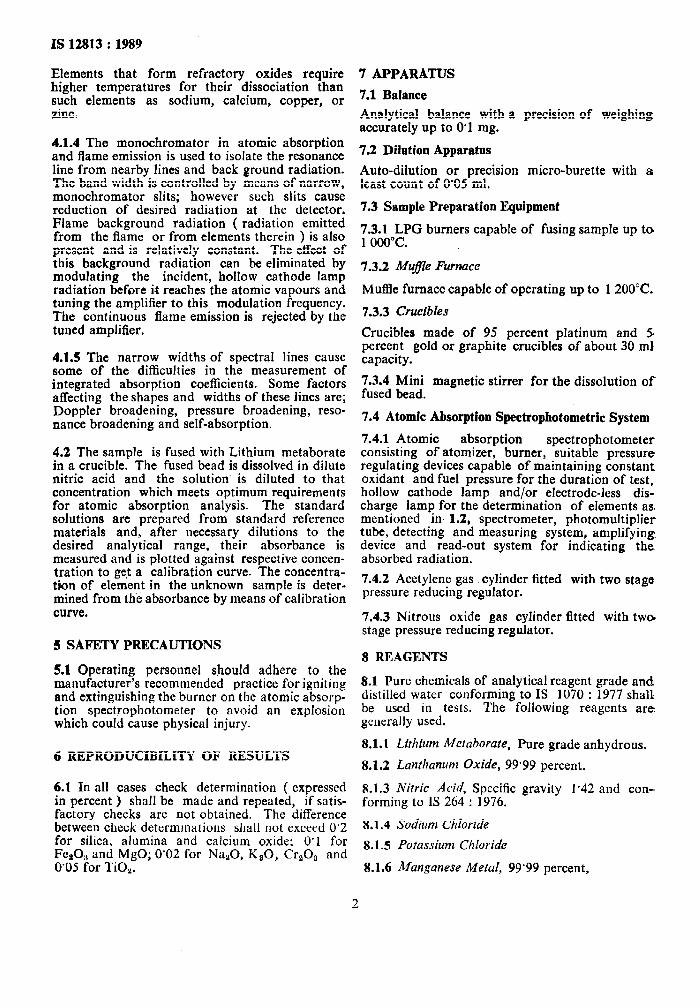
Elements that form refractory oxides require higher temperatures for their dissociation than such elements as sodium, calcium, copper, or zinc.
4.1.4 The monochromator in atomic absorption and flame emission is used to isolate the resonance line from nearby lines and back ground radiation. The band width is controlled by means of narrow, monochromator slits; however such slits cause reduction of desired radiation at the detector. Flame background radiation ( radiation emitted from the flame or from elements therein ) is also present and is relatively constant. The effect of this background radiation can be eliminated by modulating the incident, hollow cathode lamp radiation before it reaches the atomic vapours and tuning the amplifier to this modulation frequency. The continuous flame emission is rejected by the tuned amplifier.
4.1.5 The narrow widths of spectral lines cause some of the difficulties in the measurement of integrated absorption coefficients. Some factors affecting the shapes and widths of these lines are; Doppler broadening, pressure broadening, reso- nance broadening and self-absorption.
4.2 The sample is fused with Lithium metaborate in a crucible. The fused bead is dissolved in dilute nitric acid and the solution is diluted to that concentration which meets optimum requirements for atomic absorption analysis. The standard solutions arc prepared from standard reference materials and, after necessary dilutions to the desired analytical range, their absorbance is measured and is plotted against respective concen- tration to ge.t a calibration curve. The concentra- tion of element in the unknown sample is deter- mined from the absorbance by means of calibration curve.
5 SAFETY PRECAUTIONS
5.1 Operating personnel should adhere to the manufacturer’s recommended practice for igniting and extinguishing the burner on the atomic absorp- tion spectrophotometer to avoid an explosion which could cause physical injury.
6 REPRODUCIBILITY OF RESULTS
6.1 In all cases check determination ( expressed in percent ) shall be made and repeated, if satis- factory checks are not obtained. The difference between check determinations shall not exceed 0’2 for silica, alumina and calcium oxide: 0’1 for Fe*O, and MgO; 0’02 for Na,O, KaO, Cr,O, and 0’05 for TiO,.
7 APPARATUS
7.1 Balance
Analytical balance with a precision of weighing accurately up to 0.1 mg.
7.2 Dilution Apparatus
Auto-dilution or precision micro-burette with a least count of 0’05 ml.
7.3 Sample Preparation Equipment
F:GOkPG burners capable of fusing sample up to .
7.3.2 Mufle Furnace
Muffle furnace capable of operating up to 1 200°C.
7.3.3 Crucibles
Crucibles made of 95 percent platinum and 5 percent gold or graphite crucibles of about 30 mJ capacity.
7.3.4 Mini magnetic stirrer for the dissolution of fused bead.
7.4 Atomic Absorption Spectropbotometric System
7.4.1 Atomic absorption spectrophotometet consisting of atomizer, burner, suitable pressure regulating devices capable of maintaining constant oxidant and fuel pressure for the duration of test, hollow cathode lamp and/or electrode-less dis- charge lamp for the determination of elements as. mentioned in, 1.2, spectrometer, photomultiplier tube, detecting and measuring system, amplifying. device and read-out system for indicating the absorbed radiation.
7.4.2 Acetylene gas cylinder fitted with two stage pressure reducing regulator.
7.4.3 Nitrous oxide gas cylinder fitted with tw@ stage pressure reducing regulator.
8 REAGENTS
8.1 Pure chemicals of analytical reagent grade and distilled water conforming to IS 1070 : 1977 shall be used in tests. The following reagents are: generally used.
8.1. I Lithium Metaborate, Pure grade anhydrous.
8.1.2 Lanthanum Oxide, 99.99 percent.
8.1.3 Nitric Acid, Specific gravity I.42 and con- forming to IS 264 : 1976.
8.1.4 Sodium Chloride
8.1.5 Potassium Chloride
8.1.6 Manganese Metul, 99’99 percent,
2
.
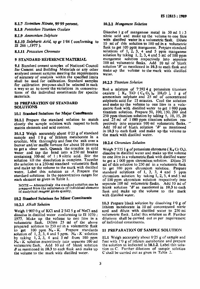
8.1.7 Strbntium Nitrate, 99’99 percent.
8.1.8 Potassium Titanium Oxalate
8.1.9 Ammonium St&hate
8.1.10 Sulphuric Acid, sp gr 1’84 ( conforming to IS 266 :,1977 ).
8.1.11 Potassium Chromate
9 STANDARD REFERENCE MATERIAL
9.1 Statidard cement samples of National Council for Cement and Building Materials or any other analyzed cement samples meeting the requirements of accuracy of analysis within the specified limits shall be used for calibration. Standard samples for calibration purposes shall be selected in such a way so as to cover the variations in concentra- tions of the individual constituents for specific materials.
10 PREPARATION OF STANDARD SOLUTIONS
10.1 Staudard Solutions for Major Constbents
10.1.1 Prepare the standard solution to match closely the sample solution with respect to both matrix elements and acid content.
10.1.2 Weigh accurately about 0’25 g of standard sample and 1’0 g of lithium metaborate in a crucible. Mix thoroughly and fuse the mii over a burner and/or muffle furnace for about 10 minutes to get a clear melt. Quench the crucible in cold water and tap the bead into a 250 ml beaker containing 100-ml of 1 : 9 nitric acid. Stir the solution till the dissolution is complete. Transfer the solution to a 250-ml standard volumetric flask and make up the volume to the mark with distilled water. Label this solution as A. Prepare the standard solutions in the concentration ranges for each element as given in Table 1.
NOTE - Alternatively the standard solution can be prepared from the salts/metals of individual elements of analytical reagent grade quality.
10.2 Standard Solutions fur Minor Constituents
10.2.1 AIkaW SoLioti
Weigh 1’907 0 g of KC1 and 2’542 5 g of NaCl and dissolve in distilled water conforming to IS 1070 : 1977. Make up the volume to one litre in a volumetric flask. Dilute 25 ml of the above prepared solution to 250 ml in a volumetric flask to get 100 ppm Na - K. Prepare standards solution of 1, 2, 3, 4 and 5 ppm. Na - K’ solution by taking I, 2, 3. 4 and 5 ml from 100 ppm Na - K solution respectively into separate 100 ml volumetric flask. Add 10 ml of blank solution f3 as mentioned in 10.3 to each flask and make up the volume to the mark with distilled water.
IS 12813 : 1989
10.2.2 Manganese Solution
Dissolve I g of manganese metal in 50 ml 1 : 3 nitric acid and make up the volume to one litre with distilled water in a volumetric flask. Dilute IO ml of this solution to 100 ml in a volumetric flask to get 100 ppm manganese. Prepate standard solutions of 1, 2, 3, 4 and 5 ppm manganese solution by taking 1, 2, 3,4 and 5 ml of 100 ppm manganese solution respectively into separate 100 ml, volumetric flasks. Add 10 ml of blank solution ‘B’ as mentioned in 10.3 to each flask and make up the volume to the mark with distilled water.
10.2.3 Titanium Solution
Boil a mixture of 7’392 4 g potassium titanium oxalate [ KB TiO ( C, 0, )a. 2H,O I, 1 g of ammonium sulphate and 25 ml of concentrated sulphuric acid for 15 minutes. Cool the solution and make up the volume to one litre in a volu- metric flask with distilled water to get 1 000 ppm titanium solution. Prepare 50, 100, 150, 200 and 250 ppm titanium solution by taking 5, 10, 15, 20 and 25 ml of 1 000 ppm titanium solution res- pectively into separate 100 ml volumetric flasks. - Add 10 ml of blank solution ‘B’ as mentioned in 10.3 to each flask and make up the volume to the mark with distilled water.
10.2.4 Chromium Solution
Weigh 3’735 1 g of potassium chr6matt ( K, Cr 0,). dissolve in distilled water and make up the volume to one litre in a volumetric flask with distilled water to get a 1 000 ppm chromium solution. Dilute 25 ml of this solution to 250 ml in a volumetric flask to get 100 ppm chromium solution. Prepare standard solutions of 1, 2, 3, 4 and 5 ppm chromium solution by taking 1, 2, 3, 4 and 5 ml of 100 ppm chromium solution respectively into separate 100 ml volumetric flasks. Add 10 ml of blank solution ‘B’ as mentioned in 10.3 to each flask and make up the volume to the mark with distilled water.
10.3 Prepare blank solution by dissolving 1’0 g of lithium metaborate in 10 ml concentrated nitric acid and dilute with distilled water to 250 ml volumetric flask. Label this solution as B. Further dilutions shall be carried out as per requirement of individual constituents.
11 PREPARATION OF SAMPLE SOLUTION
11.1 Weigh accurately about 0’25 g of sample and fuse with 1’0 g of lithium metaborate and prepare the solution as indicated in 10.1.2. Label this solu- tion as C. Further dilutions of sample solution C shall be carried out as given in Table 2.
1s 12813 : 1989
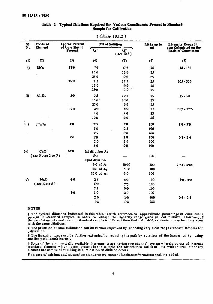
Table 1 Typical DJJutJom Required for Varionr Conditments Present in Stan&d Sample for Calibration
( Ckse 10.1.2 )
R. Approx Percent Ml of Solution of Constituent , . Ma!lYP to
Linearity Range lo ppm Calculated on tk
Present
(1)
i)
(2)
SiOr
(3)
18’0
35-o
il) AhOI 5’0
12’0
iii) FerOa 4-O
8-O
fv) CaO 65-O / ( SIC Notes 2 to 5 )
VI MgO ( ace Note 5 )
4’0
8-O
‘A’ ‘i!P ( see 10.3 )
(4) (5)
7’5 15’0 25’0 7.5
190 25-o
17’5 10’0 0’0
17-5 10’0 o-0 *
(6)
25
25 25 25 25 25
7’5 17’5 25 15-o 10’0 25 25’0 0’0 25
4’0 8’0 25 4’0 4’0 25
12’0 0-O 25
2.5 5-O 7’5 1.0 2-O 3’0
1st dilution A, 90
IInd dilution 5.0 of Ai
10’0 of A, 15’0 of Aa
5’0 25 0’0 2’0 1’0 0.0
100 100 100 100 100 100
- 100
10’00 5-00 0’0
2’5 5’0 5.0 2’5 7’5 0.0 1’0 2’0 2-O l-0 3’0 O-0
100 100 100
loo 100 loo 100
100 100
- Basis of Constituent
(7)
54 - 180
105 - 350
15-50
192 - 576
1’0 - 3’0
O-8-2-4
-
1’63 - 488
1’0 - 3’0
O-8- 2’4
NOTES
1 The typical dilutions indicated in this table is with reference to approximate percentage of constituent present in standard samples in order to obtain the linearity range given in co1 7 above. However, if the percentage of constituent in standard sample is different than that indicated, calibration may be done even, with the same dilutions. z The precision of lime estimation can be further improved by choosing very close range standard samples for calibration. 3 The linearity range can be further extended by reducing the path by rotation of the burner or by using smaller path length burner. 4 Some of the commercially available instruments are having two channel system wherein by use of internal’ standard element which is not present in the sample. the absorbance ratios of lime with internal standard’ element are computed resulting in elimination of dilution errors. § In case of calcium and magnesium standards O-1 percent lanthanum/strontium shall be added.
--_-.- __.__-~:_ ,.
IS 12813 : 1989
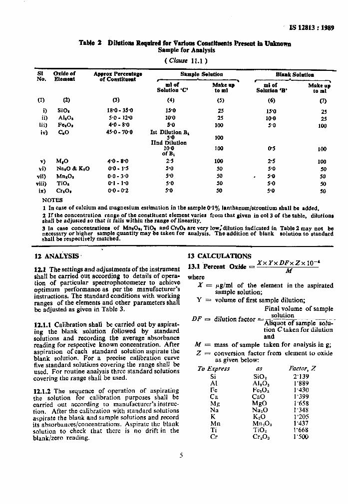
‘Table 2 Dilotions Required for Various Constituents Present in Unknown Sample for Analysis
( Clause 11.1 )
% Oxide of Element
Approx Perceatage of Constitoent
Sample Solution Blank Solution I 3
ml of I
y:;*aP ml of ,
Solation ‘C’ Solution ‘B* Make up
to ml
(1) (2) (3) (4) (5) (6) CI)
i) SiOl 18’0 - 35.0 190 25 15’0 25 ii) AlrO. 5.0 - 120 10’0 25 10-O 25
iii) Fe& 4-o - 8’0 PO 100 5.0 100 iv) GO 45-o - 70-O 1st Dil$on BI
IInd Dilution IO.0
of BI
100
100 0-S 100
v) McO 4’0 - 8.0 2.5 100 25 100 vi) NaaO & KsO 0’0 - 1’5 5.0 50 90 50
vii) MnrOa o-0 - 3.0 5’0 50 e 5.0 50 viii) TiO, 0.1 - 1-o 5-O 50 5-O 50 ix) craoa 0.0 - 0’2 5-O 50 5-O 50
NOTES 1 In case of calcium and magnesium estimation in the sample O-l% lanthanum/strontium shall he added. 2 If the concentration range of the constituent element varies from that given in co1 3 of the table, dilutions shall be adjusted so that it falls within the range of linearity. 3 In case concentrations of MnsO;, TiOx and Cra01 are very 1ow:dilution indicated in Table 2 may not be necessary or higher sample quantity may be taken for analysis. The addition of blank solution to standard shall be respectively matched.
. 12 ANAiYSIS ’ 13 CALCULATIONS
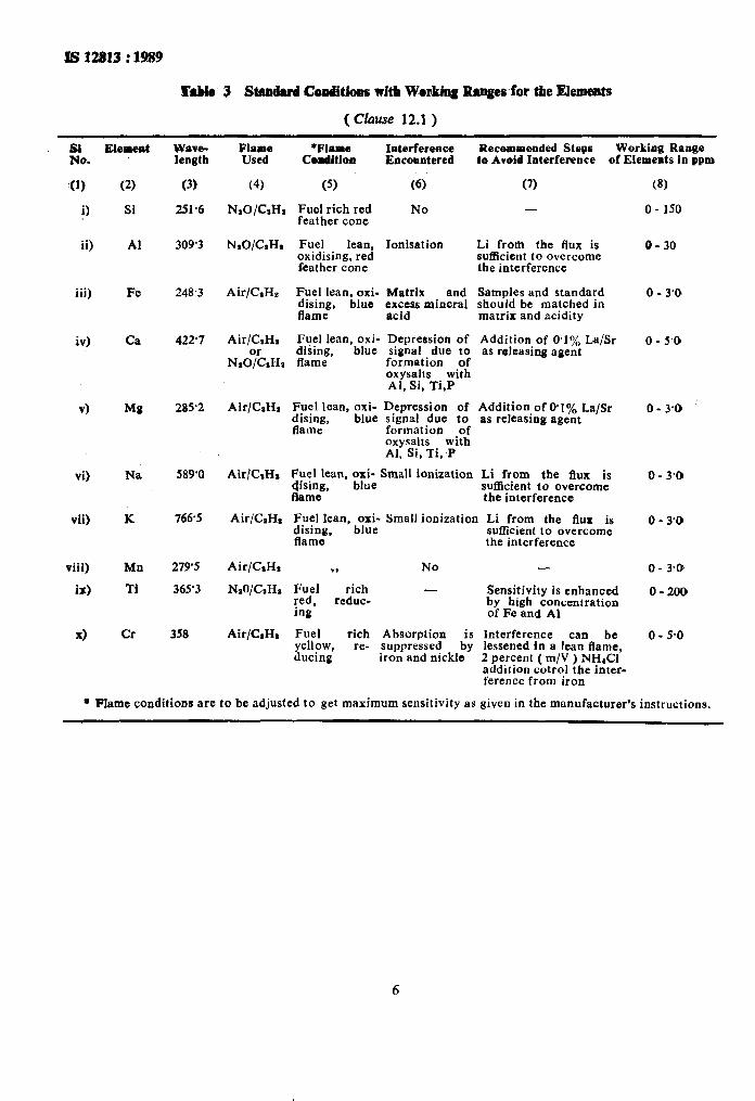
12.1 The settings and adjustments of the instrument shall be carried out according to details of opera- tion of particular spectrophotometer to achieve optimum performance as per the manufacturer’s instructions. The standard conditions with working ranges of the elements and other parameters shall be adjusted as given in Table 3.
12.1.1 Calibration shall be carried out by aspirat- ing the blank solution followed by standard solutions and recording the average absorbance reading for respective known concentration. After aspiration of each standard solution aspirate the blank solution. For a precise calibration curve five standard solutions covering the range shall be used. For routine analysis three standard solutions covering the range shall be used.
12.1.2 The sequence of operation of aspirating the solution for calibration purposes shall be carried out according to manufacturer’s instruc- tion. After the calibration with standard solutions aspirate the blank and sample solutions and record its absorbances/concentrations. Aspirate the blank solution to check that there is no drift in the blank/zero reading.
13.1 ‘Percent Oxide = XxYxDFxZxlO-6
M where
X = pg/ml of the element in the aspirated sample solution;
Y = volume of first sample dilution; Final volume of sample
DF = dilution factor = solution
Aliquot of sample solu- tion C taken for dilution and
M = mass of sample taken for analysis in g; Z = conversion factor from element to oxide
as given below:
To Express as Facror, Z
El SiO, 2’139 A&O, 1’889
Fe Fe203 1.430 Ca cao 1’399 Mg MO 1’658 Na Nan0 1’348 K K20 1’205
P Mn,09 1’437 TiO,, 1’668
Cr Crzd3 1’500
5
IS 12813 : 1989
R’db 3 Stamhrd Conditions with WoAhg Rmges for the Elements
( Chse 12.1 )
Fo. (1)
i)
ii)
iii)
iv)
vi)
vii)
viii)
is)
x)
Elered
(2)
Si
Al
Fe
Ca
Mg
K
Mn
Ti
Cr
Wave- ,lengtb
(3)
251.6
309'3
248.3
422.7
2aY2
589'0
7665
279'5
365'3
358
Flame *Flame Interference Used cc%8ditioll Encountered
(4) (5) (6)’
NIO/CnHI Fuel rich red No feather cone
NIO/CIHI Fuel lean. Ionisation oxidising, red feather cone
Air/CIHe Fuel lean. oxi- ,Matrix and dising, blue excess mineral flame acid
Air/GHa Fuel lean, oxi- Depression of or diiing, blue signal due to
N,O/GHo flame formation of oxysalts with Al, Si, Ti,P
Air/CsHs zu&ean, oxi- D.epression of
flame ’ blue slgnal due to
formation of oxysalts with Al. Si, Ti. P
RecolMneoded Steps Lo Avoid Interference
Working Range of Elemeats in ppm
(7)
-
Li from the flux is sufficient to overcome the interference
Samples and standard should be matched in matrix and acidity
Addition of 0.1% La/Sr as releasing agent
Addition of WI% as releasing agent
La/Sr
Air/C,H, Fpel lean, $te Small ionization Li frpm the flux is $s4nlZ, sufficient to overcome
the interference
Air/CaHr ;;;;tan, b;;t Small ionization Li frpm the flux is
flame l
suffic8ent to overcome the interference
Air/GHr 9, No -
NIO/GH~ Fuel rich - red, reduc-
Sensitivity is enhanced
ing by high concentration of Fe and Al
Air&H, Fuel rich Absorption is Interference can be yellow, re- suppressed ducing
by lessened in a lean flame, iron and nickle 2 percent ( m/V ) NH&l
addition cotrol the inter- ference from iron
(8)
0 - 150
o- 30
0 - 3’0
0 - 5’0
0 - 3’0
0 - 3.0
0 - 3’0
0 - 3.0
O-200
0 - 5.0
l Flame conditions are to be adjusted to get maximum sensitivity as given in the manufacturer’s instructions.
IS 12813 : 1989
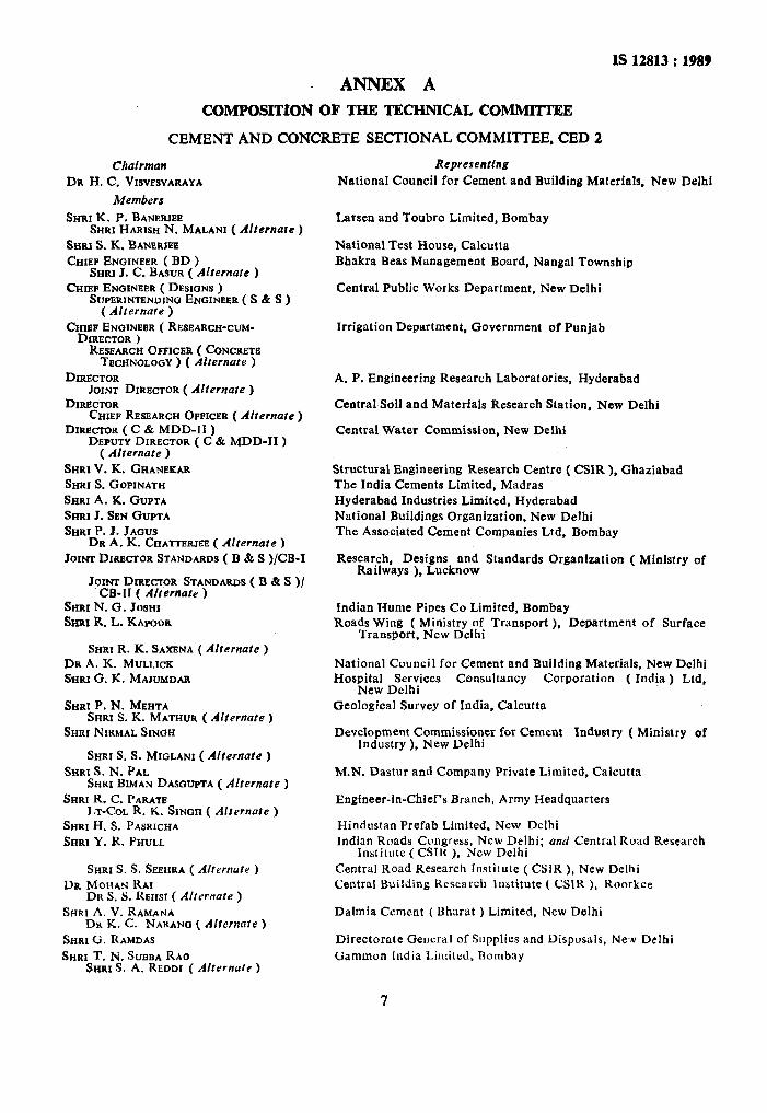
ANNEX A
COMPOSITION OF THE TECHNICAL COMMlTTEE
CEMENT AND CONCRETE SECTIONAL COMMITTEE, CED 2
Chairman
DR H. C. VISVESVARAYA
Members
SHRI K. P. BANERJE~ SHRI HARISH N. MALANI ( AIternare )
SHRI S. K. BANERW
CHIRP ENGINEER ( BD ) SHRI J. C. BASUR ( Afternate )
CHIEF ENQINIXR ( DESIGNS ) SUPERINTENDING ENGINEIIR ( S & S )
( Alfernate ) CHIEF ENGINEER ( RESEARCH-CUM-
DIRECTOR ) RESEARCH OPPIC~R ( CONCRETB
TECHNOLOC+Y ) ( Alternate )
DIRECTOR JOINT DIRECTOR ( Afternate )
DIRECTOR CHIEP RESEARCH OPPICER f Afternate j
* r
DIRE~R ( C & MDD-II ) DEPUTY DIRECTOR ( C & MDD-II )
( Alternate ) SHRI V. K. GHANEKAR
SHRI S. GOPINATH
SHRI A. K. GUPTA
SHRI J. SEN GUPTA
SHRI P. J. JAWS DR A. K. CHA~ER~EE ( Alternate )
JOINT DIRECTOR STANDARDS ( B & S )/CB-I
JOINT DIRECTOR STANDARDS ( B dr S )/ C&H ( Alternate )
SHRI N. G. Josnr SHRI R. L. KA~~OR
SHRI R. K. SAXENA ( Alternate )
DR A. K. MULLICK
SHRI G. K. MAJUMDAR
SHRI P. N. MEHTA SHRI S. K. MATHUR ( Alternate )
SHRI NIRMAL SINQH
SHRI S. S. MIGLANI ( Alternate ) SHRI S. N. PAL
SHRI BIMAN DA~~UPTA ( Alternate ) SHRI R. C. PARATE
LT-COL R. K. SINOH ( Afternate ) SHRI H. S. PASRICHA
SHRI Y. R. PHULL
SHRI S. S. SIXHRA ( Alternofe ) DR MOHAN RAI
DR S. S. REHSI ( Alrernote ) SHRI A. V. RAMANA
DR K. C. NARANO ( Alternate ) SHRI G. RAMDAS
SHRI T. N. SUSBA RAO SHRI S. A. REDDI ( Altcrnafe )
Representing
National Council for Cement and Building Materials, New Delhi
Larsen and Toubro Limited, Bombay
National Test House, Calcutta Bhakra Beas Management Board, Nangal Township
Central Public Works Department, New Delhi
Irrigation Department, Government of Punjab
A. P. Engineering Research Laboratories, Hyderabad
CentralSoil and Materials Research Station, New Delhi
Central Water Commission, New Delhi
Structural Engineering Research Centre ( CSIR ), Ghaziabad The India Cements Limited, Madras Hyderabad Industries Limited, Hyderabad National Buildings Organization. New Delhi The Associated Cement Companies Ltd. Bombay
Research, Designs and Standards Organization ( Ministry of Railways ). Lucknow
Indian JIume Pipes Co Limited, Bombay Roads Wing ( Ministry of Transport ), Department of Surface
Transport, New Delhi
National Council for Cement and Building Materials, New Delhi Hospital Services Consultancy Corporation ( India ) Ltd,
New Delhi Geological Survey of India, Calcutta
Development Commissioner for Cement Industry ( Ministry of Industry ), New Delhi
M.N. Dastur and Company Private Limited, Calcutta
Engineer-in-Chief’s Branch, Army Headquarters
Hindustan Prefab Limited. New Delhi Indian Roads Congress, New Delhi; and Central Road Research
Institute ( CSIR ). New Delhi Central Road Research Institute ( CSIR ), New Delhi Central Building Research Institute ( CSIR ), Roorkee
Dalmia Cement ( Bhnrat ) Limited, New Delhi
Directorate General of Supplies and Disposals, New Delhi
Gammon India Limited, Bombay
7
IS 12813 : 1989
Membera
DR M. RAMAIAH DR A. G. MADHAVA RAO ( Alternate )
Reprcserttn~
Structural Engineering Research Centre ( CSIR ), Ma&as
SHRI A. U. RIJHSINOHANI SHRI C. S. SHARMA ( AIternofe )
SECRETARY
Cement Corporation of India, New Delhl
SHRI K. R. SAXENA ( Alternate) Central Board of Irrigation and Power, New Delhi
SUPERINTENDING ENGINEER ( DESIGNS ) Ex~cur~ve ENGINEER ( SMD DIVISION )
Public Works Department, Government of Tamil Nadu
( AIternate ) SHRI L. SWAROOP Orissa Cement Limited, New Delhi
SHRI H. BHATTACHARYA ( Alrernate )
SHRI S. K. GUHA THAKURTA Gannon Dunkerly & Co Ltd. Bombay SHRI S.P. SANKARNARAYANAN
( A/f ernute )
DR H. C. VISV~SVARAYA SHRI D. C. CHATURVEDI ( Affornore )
SHRI G. RAMAN. Director ( Civ Engg )
The Institution of Engineers ( India ), Calcutta
Director General, BIS ( Ex-o&lo Member )
Secretary
SHRI N. C. BANDYOPADRYAY Joint Director ( Civ Bngg ), BIS
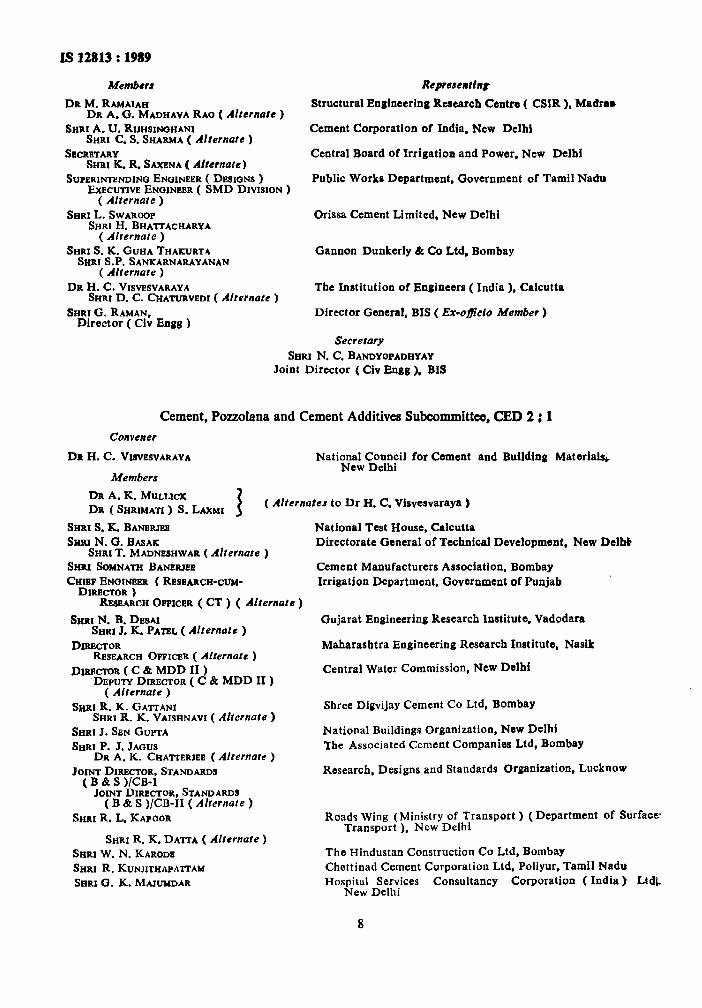
Cement, Pozzolana and Cement Additives Subcommittee, CED 2 : 1
Convener
DR H. C. VM~~SVARAYA
Members
National Council for Cement and Building Materials, New Delhi
DR A. K. MULLICK DR ( SRRIMA~ ) S. LAXMI 3
( AIternotes to Dr H. C. Visvesvaraya )
SHRI S. K. BANERJFZ SHRI N. 0. BASAK
SHRI T. MADNESHWAR ( Alternate ) SHRI SOMNATH BANERJ@E
CHIEF ENGINEER ( RESEARCH-CUM- DIRECTOR )
National Test House, Calcutta Directorate General of Technical Development, New Dtlbb
Cement Manufacturers Association, Bombay
Irrigation Department, Government of Punjab
Rasa.4~~~ OFTICER ( CT ) ( AIternutc )
SEIRI N. B. DESAI SHRI J. K. PATEL ( Afternate )
DIRECTOR &SEARCH OFFICER ( Alternate )
Dmc~oa(c&MDDIi) DEPUTY DIRECTOR ( C & MDD II )
( Alternufe )
SXRI R. K. GA~ANI SHRI R. K. VAISHNAVI ( Alternate )
SHRI J. SEN GUPTA
SHRI P. J. JAQUS DR A. K. CHATTERJEE (Alternate )
JOINT DIRECTOR, STANDARDS t B & S l/CB-I _ JOINTDIRECTOR, STANDARDS
( B & S )/CB-II ( Alternate )
SHRI R. L. KAPOOR
SHRI R. K. DATTA ( Altemute ) SHRI W. N. KARODE
SHRI R. KUNJITHAPA~AH
SHRI 0. K. MAJ~DAR
Gujarat Engineering Research Institute, Vadodara
Maharashtra Engineering Research Institute, Nasik
Central Water Commission, NCW Delhi
Shree Digvijay Cement Co Ltd, Bombay
National Buildings Organization, New Delhi Tbe Associated Cement Companies Ltd, Bombay
Research, Designs and Standards Organization, Lucknow
Road3 Wing (Ministry of Transport ) (Department of Surface Transport ), New Delhi
The Hindustan Construction Co Ltd. Bombay Chettinad Cement Corporation Ltd. Poliyur, Tamil Nadu Hospital Services Consultancy Corporation ( India ) LtdL
New Delhi
8
IS 12813 : 1989
Members
SHRI K. P. MOHIDEEN SHRI NIRMAL SINGH
SHRI S. S. MI~LANI ( Alternate ) SHRI Y. R. PHULL
SHRI S. S. SEEHRA ( Alternate )
SHRI A. V. RAMANA DR K. C. NARANG ( Alternate )
COL V. K. RAO SHRI N. S. GALANDB ( Afternate )
’ SHRI S. A. REDDI
DR S. S. REHSI DR IRSHAD MASOOD ( Alternate )
SHRI A. U. RIJIISINOHANI
SHRI M. P. SINUH
SUPERINTENDIN~ ENGINEER (D) SENIOR DEPUTY CHIEF ENOINBER
( GENERAL ) ( Alternate ) SHRl L. SWAROOP
SARI H. BHA-LTACHARYA ( Alternate )
SrrRI v. M. WAD
Representing
Central Warehousing Corporation, New Delhi Development Commissioner for Cement Industry ( Ministry of
Industry )
Central Road Research Institute ( CSIR ), New Delhi
Dalmia Cement ( Bharat ) Ltd, New Delhi
Engineer-in4hief’s Branch, Army Headquarters
Gammon India Ltd, Bombay Central Building Research Institute ( CSIR ), Roorkee
Cement Corporation of India Ltd, New Delhi
Federation of Mini Cement Plants, New Delhi
Public Works Department, Government of Tamil Nadu
Orissa Cement Ltd, New Delhi
Bhilai Steel Plant, Bhilai
9
Standard Mark
The use of the Standard Mark is governed by the provisions of the Bureau of hdian Stundards Act, I986 and the Rules and Regulations made thereunder. The Standard Mark on products covered by an Indian Standard conveys the assurance that they have been produced to comply with the requirements of that standard under a well defined system of inspection, testing and quality control which is devised and supervised by BIS and operated by the producer, Standard marked products are also continuously checked by BIS for conformity to that standard as a further safeguard. Details of conditions under which a license for the use of the Standard Mark may be granted to nlanufacturers or producers may be obtained from the Bureau of lndinn Standards.
Bweaa of Indian Standards
BIS is a statutory institution established under the &reau of Indian Standards Act, 1986 to promote harmonious development of the activities of standardization, marking and quality certification of goods and attending to connected matters in the country.
copyright
BIS has the copyright of all its publications. No part of these publications may be reproduced in any form without the prior permission in writing of BIS. This does not preclude the free use, in the course of implementing the standard, of necessary details, such as symbols and sizes, type or grade designations. Enquiries relating to copyright be addressed to the Director ( Publications ), BIS.
Revision of Indian Standards
Indian Standards are reviewed periodically and revised, when necessary and amendments, if any, are issued from time to time. Users of Indian Standards should ascertain that they are in possession of the latest amendments or edition. Comments on this Indian Standard may be sent to BIS giving the following reference:
Dot : No. CED 2 ( 4437 )
Amendments Issued Since Poblication
Amend No. Date of Issue Text Affected
BUREAU OF INDIAN STANDARDS
Headquarters :
Manak Bhavan, 9 Bahadur Shah Zafar Marg, New Delhi 110002 Telephones : 331 01 31, 331 13 75 Telegrams : Manaksanstha
( Common to all O&es )
Regional Offices :
Central : Manak Bhavan, 9 Bahadur Shah Zafar Marg NEW DELHI 110002
Eastern : l/14 C. I. T. Scheme VII, M, V. I. P. Road, Maniktola CALCUTTA 700054
Telephone
I 331 01 31 331 13 75
37 86 62
Northern : SC0 445-446, Sector 35-C, CHANDIGARH 160036 2 1843
Southern : C. I. T. Campus, IV Cross Road, MADRAS 600113 41 29 16
Western : Manakalaya, E9 MIDC, Marol, Andheri ( East ) BOMBAY 400093
6 32 92 95
Branches : AHMADABAD. BANGALORE. BHOPAL. BHUBANESHWAR. COIMBATORE. FARIDABAD. GHAZIABAD. GUWAHATI. HYDERABAD. JAIPUR. KANPUR. PATNA. TRIVANDRUM.
Printed at Printwell Printers, Delhi. India