IS 10714-40 (2006): Technical drawings - General ... · inscriptions on the drawing (dimensions,...
13
Disclosure to Promote the Right To Information Whereas the Parliament of India has set out to provide a practical regime of right to information for citizens to secure access to information under the control of public authorities, in order to promote transparency and accountability in the working of every public authority, and whereas the attached publication of the Bureau of Indian Standards is of particular interest to the public, particularly disadvantaged communities and those engaged in the pursuit of education and knowledge, the attached public safety standard is made available to promote the timely dissemination of this information in an accurate manner to the public. इंटरनेट मानक “!ान $ एक न’ भारत का +नम-ण” Satyanarayan Gangaram Pitroda “Invent a New India Using Knowledge” “प0रा1 को छोड न’ 5 तरफ” Jawaharlal Nehru “Step Out From the Old to the New” “जान1 का अ+धकार, जी1 का अ+धकार” Mazdoor Kisan Shakti Sangathan “The Right to Information, The Right to Live” “!ान एक ऐसा खजाना > जो कभी च0राया नहB जा सकता ह ै” Bhartṛhari—Nītiśatakam “Knowledge is such a treasure which cannot be stolen” IS 10714-40 (2006): Technical drawings - General Principles of Presentation, Part 40: Basic Conventions for cuts and sections [PGD 24: Drawings]
Transcript of IS 10714-40 (2006): Technical drawings - General ... · inscriptions on the drawing (dimensions,...

Disclosure to Promote the Right To Information
Whereas the Parliament of India has set out to provide a practical regime of right to information for citizens to secure access to information under the control of public authorities, in order to promote transparency and accountability in the working of every public authority, and whereas the attached publication of the Bureau of Indian Standards is of particular interest to the public, particularly disadvantaged communities and those engaged in the pursuit of education and knowledge, the attached public safety standard is made available to promote the timely dissemination of this information in an accurate manner to the public.
इंटरनेट मानक
“!ान $ एक न' भारत का +नम-ण”Satyanarayan Gangaram Pitroda
“Invent a New India Using Knowledge”
“प0रा1 को छोड न' 5 तरफ”Jawaharlal Nehru
“Step Out From the Old to the New”
“जान1 का अ+धकार, जी1 का अ+धकार”Mazdoor Kisan Shakti Sangathan
“The Right to Information, The Right to Live”
“!ान एक ऐसा खजाना > जो कभी च0राया नहB जा सकता है”Bhartṛhari—Nītiśatakam
“Knowledge is such a treasure which cannot be stolen”
“Invent a New India Using Knowledge”
है”ह”ह
IS 10714-40 (2006): Technical drawings - General Principlesof Presentation, Part 40: Basic Conventions for cuts andsections [PGD 24: Drawings]


IS 10714( Pati 40 ): 2006ISO 128-40:2001
mm
/ndian Standard
TECHNICAL DRAWINGS — GENERAL PRINCIPLESOF PRESENTATION
PART 40 BASIC CONVENTIONS FOR CUTS AND SECTIONS
Ics 01.100.01
@ BIS 2006
BUREAU OF INDIAN STANDARDSMANAK BHAVAN, 9 BAHADUR SHAH ZAFAR MARG
NEW DELHI 11GO02
Apri/ 2006 Price Group 3

Drawings Sectional Committee, PG 24
NATIONAL FOREWORD
This Indian Standard (Part 40) which is identical with ISO 128-40 : 2001 ‘Technical drawings —General principles of presentation — Part 40: Basic conventions for cuts and sections’ issued by theInternational Organization for Standardization (ISO) was adopted by the Bureau of Indian Standards onthe recommendation of the Drawings Sectional Committee and approval of the Production and GeneralEngineering Division Council.
ISO 128 was published in 1982 and was accordingly adopted as.lS 10714:1983. ISO 128:1982 waswithdrawn and published again in several parts, In view of this, Drawin-gs Sectional Committee decidedto adopt ISO 128-40:2001 as IS 10714 (Part 40).
This standard specifies general principles for presenting cuts and sections applicable to all kinds oftechnical drawings (mechanical, electrical, architectural, civil engineering, etc), following the orthographicprojection methods specified in ISO 5456-2. For areas on cuts and sections, representation is accordingto ISO 128-50. The requirements of reproduction, including microcopying in accordance w’ith ISO 6428has also been taken care of in this standard.
It is applicable for all kinds of technical drawings, imluding, for example, those used in mechanicalengineering and construction. It K applicable to both manual and computer-based drawings. !t is notapplicable to three-dimensional CAD models.
The other parts of this series are given as follows:
IS 10714 (Part 20) :2001 Technical drawings — General principles of presentation: Part 20Basic conventions for lines
IS 10714 (Part 21) :2001 Technical drawings — General principles of presentation: Part 21Preparation of lines by CAD systems
The text of ISO Standard has been approved as suitable for publication as an Indian Standard withoutdeviations. Certain conventions are, however, not identical to those used in Indian Standards. Attentionis particularly drawn to the following:
a) Wherever the words, ‘International Standard’ appear, referring to this sttiard, they shQuld beread as ‘indian Standard’.
b) Comma ( , ) has been used as a decimal marker while in Indian Standards, the current practiceis to use a point ( ) as the decimal marker.
In this adopted standard, reference appears to certain International Standards for which Indian Standardsalso exists. “The corresponding Indian Standards, which are to be substituted in their places, are listedbelow along with their degree of equivalence for the editions indicated:
International Standard
ISO 3098-0:1997 Technical productdocumentation — Lettering —Part O : General requirements
ISO 5456-2 : 1996 Technicaldrawings — Projection methods —Part 2: Orthographic representations
ISO 6428 : 1982 Technicaldrawings — Requirements formicrocopying
Corresponding Indian Standard Degree of Equivalence
IS 9609 (Pa-rt O) :2001 Technical Identicalproduct documentation — Lettering:Part O“General requirements
IS 15021 (Part 2) :2001 Technical dodrawings — Projection methods:Part 2 Orthographic representations
IS 10164: 1985 Requirements to doexecute technical drawings formicrocopying (first revision)
( Continued on third cover)
IS 10714 (Pati 40) :2006ISO 1284:2001
Indian Standard
TECHNICAL DRAWINGS — GENERAL PRINCIPLESOF PRESENTATION
PART 40 BASIC CONVENTIONS FOR CUTS AND SECTIONS
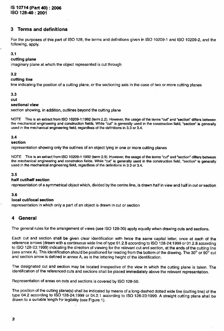
1 Scope
This part of ISO 128 specifies the general principles for presenting cuts and sections applicable to all kinds oftechnical drawings (mechanical, electrical, architectural, civil engineering, etc.) following the orthographic projectionmethods specified in ISO 5456-2. For areas on ‘cuts and sections, representation is according to ISO 128-50.
Attention has also been given in this part of ISO 128 to the requirements of reproduction, including microcopying inaccordance with ISO 6428.
2 Normative references
The following normative documents contain provisions which, through reference in this text, constitute provisions ofthis part of ISO 128. For dated references, subsequent amendments to, or revisions of, any of these publications donot apply. However, parties to agreements based on this part of ISO 128 are encouraged to investigate the possibilityof applying the most recent editions of the normative documents indicated below. For undated references, the latestedition of the normative document referred to applies. Members of ISO and IEC maintain registers of currently validInternational Standards.
ISO 128-23:1999, Technical drawings — Geneml principles of presentation — Part 23: Lines on constructiondrawings
ISO 128-24:1999, Technics/ drawings — General principles of presentation — Part 24: Lines on mechanicalengineering drawings.
ISO 128-30, Technical drawings — General principles of presentation — Part 30: Basic conventions for views.
ISO 128-50, Technical drawings — General principles of presentation — Part 50: Basic conventions for representingareas on cuts and sections.
ISO 3098-0, Technical product documentation — Lettering — Part O: General requirements.
ISO 5456-2, Technical drawings — Projection methods — Part 2: Orthographic representations.
ISO 6428, Technical drawings — Requirements for microcopying,
ISO 10209-1, Technical product documentation — Vocabulary — Part 1: Terms relating to technical drawings:general and types of drawings.
ISO 10209-2, Technical product documentation — Vocabulary — Part 2: Terms relating to projection methods.
ISO 81714-1, Design of graphical symbols for use in the technical documentation of products — Part 1: Basic rules.
1
IS 10714 (Part 40) :20061S0 1284:2001
3 Terms and definitions
For the purposes of this part of ISO 128, the terms and definitions given in ISO 10209-1 and ISO 10209-2, and-thefollowing, apply.
.
3.1
cutting plane
imaginary plane at which the object represented is cut through
3.2
cutting line
line indicating the position of a cutting plane, or the sectioning axis in the case of two or more cutting planes
3.3
cut
sectional view
section showing, in addition, outlines beyond the cutting plane
NOTE This is an extract from ISO 10209-1:1992 (term 2.2). However, the usage of the terms “cW and “section” differs betweenthe mechanical engineering and construction fields. While “cut” is generally used in the construction field, “section” is generallyused in the mechanical engineering field, regardless of the definitions in 3.3 or 3.4.
3.4
sectionrepresentation showing only the outlines of an object lying in one or more cutting planes
NOTE This is an extract from ISO 10209-1:1992 (term 2.9). However, the usage of the terms “cur and “section” differs betweenthe mechanical engineering and constructionfields. While “cut” is generally used in the construction field, “section” is generallyused in the mechanical engineering field, regardless of the definitions in 3.3 or 3.4.
3.5
half cutialf section
representation of a symmetrical object which, divided by the centre line, is drawn half in view and half in cut or section
3.6
local cutilocal section
representation in which only a part of an object is drawn in cut or section
4 General
The general rules for the arrangement of views (see ISO 128-30) apply equally when drawing cuts and sections.
Each cut and section shall be given clear identification with twice the same capital letter, once at each of thereference arrows (drawn with a continuous wide line of type 01.2.8 according to ISO 128-24:1999 or 01.2.8 accordingto ISO 128-23:1999) indicating the direction of viewing for the relevant cut and section, at the ends of the cutting line(see annex A). This identification should be positioned for reading from the bottom of the drawing. The 30° or 90° cutand section arrow is defined in annex A, as is the lettering height of the identification.
The designated cut and section may be located irrespective of the view in which the cutting plane is taken. Theidentification of the referenced cuts and sections shall be placed immediately above the relevant representation.
Representation of areas on cuts and sections is covered by ISO 128-50.
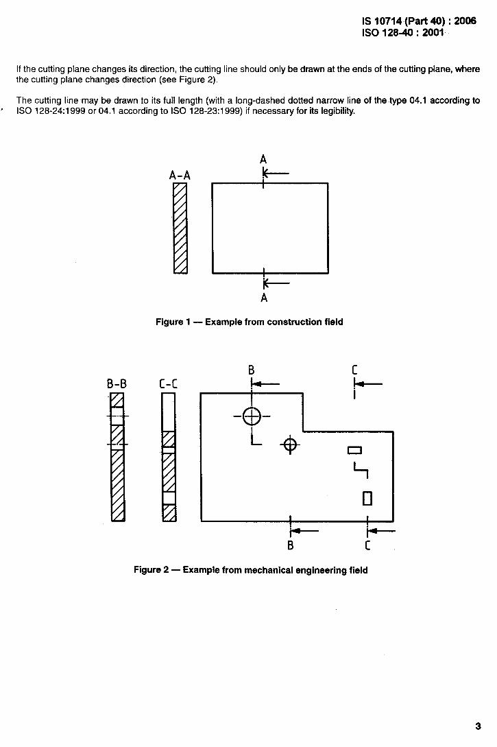
The position of the cutting plane(s) shall be indicated by means of a long-dashed dotted wide line (cutting line) of thetype 04.2 according to 1S0 128-24:1999 or 04.2.1 according to ISO 128-23:1999. A straight cutting plane shall bedrawn to a suitable length for legibility (see Figure 1).
2
IS 10714 -(Pad 40) :2008ISO 1284:2001
If the cutting plane changes its direction, the cutting line should only be drawn at the ends of the cutting plane, wherethe cutting plane changes direction (see Figure 2).
The cutting line may be drawn to its full length (with a long-dashed dotted narrow line of the type 04.1 according to. ISO 128-24:1999 or 04.1 according to ISO 128-23:1999) if necessary for its legibility.
B-B
I
t
‘+A
figure 1 — Example from construction field
c-cB c
B cHgure 2 — Example from mechanical engineering field
IS 10714 (Part 40) :2006ISO 128-40:2001
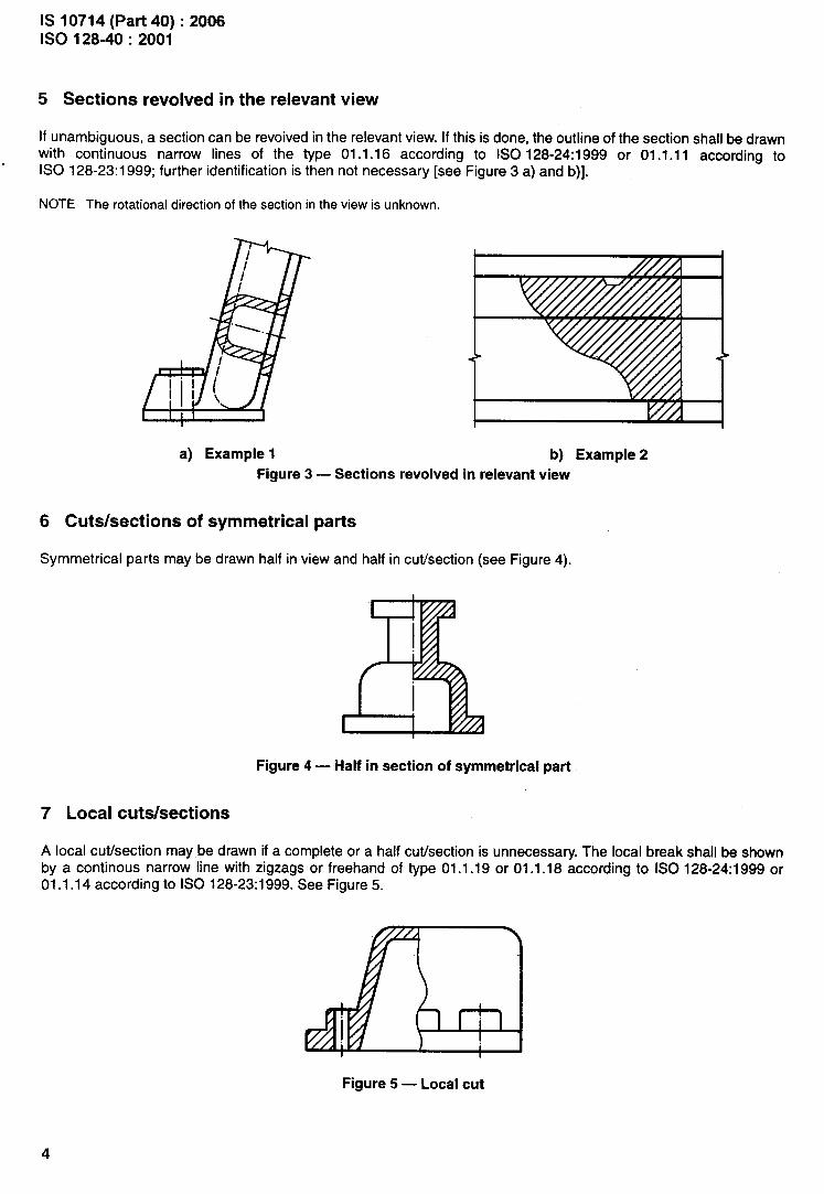
5 Sections revolved in the relevant view
If unambiguous, a section can be revoived in the relevant view. If this is done, the outline of the section shall be drawnwith continuous narrow lines of the type 01.1.16 according to ISO 128-24:1999 or 01.1.11 according to
.ISO 128-23:1 999; further identification is then not necessary [see Figure 3 a) and b)].
NOTE The rotational direction of the section in the view is unknown.
a) Example 1 b) Example 2
Figure 3 — Sections revolved in relevant view
6 Cuts/sections of symmetrical parts
Symmetrical parts may be drawn half in view and half in cutisection (see Figure 4).
Figure 4 — Half in section of symmetrical part
7 Local cuts/sections
A local cuffsection may be drawn if a complete or a half cutisection is unnecessary. The local break shall be shownby a continous narrow line with zigzags or freehand of type 01.1.19 or 01.1.18 according to ISO 128-24:1999 or01.1.14 according to ISO 128-23:1999. See Figure 5.
Figure 5 — Local cut
4

IS 10714 (Pad 40): 2008ISO 1284:2001
Annex A(normative)
Graphical symbols
A.1 General
In order to harmonize the sizes of the graphical symbols specified in this part of ISO 128 with those of the otherinscriptions on the drawing (dimensions, tolerances, etc.), the rules given in ISO 81714-1 shall apply.
The cut and section identification lettering height, h, shall be larger than the normal lettering on the technical drawingby a factor of h.
Within Figures A.1 and A.2, lettering type B, vertical, according to ISO 3098-0, applies. Other lettering types are alsopermitted.
A.2 Cut and section arrows
See Figure A. 1 for 30° cut and section arrows, and Figure A.2 for 90° cut and section arrows.
0
0m
Figure A.1
0
0m
Figure A.2
5

IS 1W14 (Pati 40): 2006lSO128~ :2001
Bibliography
[1] ISO 128-20, Twhnica/ drawings — General principles of presentation — Part 20: Basic conventions for lines.
.

( Continued from second cover)
Inferrrational Standard
ISO 10209-1:1992 Technical productdocummtation — Vocabulary —
, Part 1 : Terms relating to technicaldrawings general and types ofdrawings
ISO 10209-2:1993 Technical productdocumentation — Vocabulary —Part 2: Terms relating to projectionmethods
Corresponding Indian Standard Degree of Equivalence
IS 8930 (Part 1) : 1995 Technical Identical
product documentation — Vocabulary:Part 1 Terms relating to technicaldrawings general and types ofdrawings
IS 8930 (Part 2) : 2001 Technicalproduct documentation —Vocabulary:Part 2 Terms relating to projectionmethods
do
The Sectional Committee responsible for formulation of this standard has reviewed the provisions ofthe following International Standards for which references have been made in the text and decided thatthey are acceptable for use in conjunction with this standard:
International Standard Title
ISO .128 -23:1999 Technical drawings — General principles of presentation — Part 23:Lines on construction drawings
ISO 128-24:1999 Technical drawings — General principles of presentation — Part 24:Lines on mechanical engineering drawings
ISO 128-30 Technical drawings — General principles of presentation — Part 30:Basic conventions for views
ISO 128-50 Technical drawings — General principles of presentation — Part 50:Basic conventions for representing areas on cuts and sections
ISO 81714-1 Design of graphical symbols for use in the technical documentation ofproducts — Part 1 : Basic rules

Bureau of Indian Standards
BIS is a statutory institution established under the Bureau of Indian Standards Act, 1986 to promoteharmonious development of the activities of standardization, marking and quality certification ofgoods and attending to connected matters in the country.
Copyright
BIS has the copyright of all its publications. No part of these publications maybe reproduced in anyform without the prior permission in writing of BIS. This does not preclude the free use, in the courseof implementing the standard, of necessary details, such as symbols and sizes, type or gradedesignations. Enquiries relating to copyright be addressed to the Director (Publications), BIS.
Review of Indian Standards
Amendments are issued to standards as the need arises on the Qasis of comments. Standards arealso reviewed periodically; a standard along with amendments is reaffirmed when such reviewindicates that no changes are needed; if the review indicates that changes are needed, it is ?akenup for revision. Users of tndian Standards should ascertain that they are in possession of the latestamendments or edition by referring-to the latest issue of ‘BIS Catalogue’ and ‘Standards : MonthlyAdditions’.
This Indian Standard has been developed from Doc : PG 24/MGP 24 (0517).
Amendments Issued Since Publication
Amend No. Date of Issue Text Affected
BUREAU OF INDIAN STANDARDS
Headquarters:
Manak Bhavan, 9 Bahadur Shah Zafar Marg, New Delhi 110002Telephones: 23230131, 23233375, 23239402 Website: www.bis.org.in
Regional Offices :
Central :
Eastern :
Northern :
Southern :
Western :
Branches:
Manak Bhavan, 9 Bahadur Shah Zafar MargNEW DELHI 11 OOO2
1/14 C. 1. T. Scheme Vll M, V. 1. P. Road, KankurgachiKOLKATA 700054
SCO 335-336, Sector 34-A, CHANDIGARH 160022
C. 1.T. Campus, IV Cross Road, CHENNAI 600113
Manakalaya, E9 MlDC, Marol, Andheri (East)MUMBAI 400093
AHMEDABAD. BANGALORE. BHOPAL.FARIDABAD. GHAZIABAD. GUWAHATI.LUCKNOW. NAGPUR. PARWANOO,
Telephones
[
2323761723233841
[
23378499,2337856123378626,23379120
{
26038432609285
{2254 1216,2254 14422254 2519, 2254 2315
{
28329295,2832785828327891,28327892
BHUBANESHWAR. COIMBATORE..HYDERABAD. JAIPUR. KANPUR.
PATNA. PUNE. .RAJKOT.THIRUVANANTHAPURAM. VIS”AK”HAPATNAM.
Printedat New IndiaPrintingPress,Khurja,India