IRON DIAPHRAGM, GATE, GLOBE & CHECK v ALvEs€¦ · · 2015-05-15Uniflo Check Valve (Non-Return)...
28
www.australianpipelinevalve.com.au IRON DIAPHRAGM, GATE, GLOBE & CHECK VALVES
Transcript of IRON DIAPHRAGM, GATE, GLOBE & CHECK v ALvEs€¦ · · 2015-05-15Uniflo Check Valve (Non-Return)...

www.australianpipelinevalve.com.au
IRON DIAPHRAGM, GATE, GLOBE & CHECK vALvEs

Q U A L I T Y V A LV E M A N U FA C T U R E R
QUALITY COMMITMENT
Quality is Our First Priority, and is
achieved by embracing a philosophy
of Total Quality Commitment.

ContentsCheck Cast Iron - Class 125/250
Combination Sight Glass/Check Valve Uniflo Check Valve (Non-Return) Type ‘N’Uniflo Check Valve (Non-Return) Type ‘NX’
Gate Cast Iron - Class 125/250Globe Cast Iron - Class 125/250
Diaphragm Valve Weir (A) & Straight Through (KB) Knife Gate Valve - DC Series
Knife Gate Valve - DC Series - Part Number System
Page 4Page 5Page 6Page 7Page 8-9Page 10Page 11Page 12-23Page 24
AUSTRALIAN PIPELINE VALVE®
70-78 Stanbel Road Salisbury Plain South Australia 5109Telephone +61 (0)8 8285 0033 Fax +61 (0)8 8285 0044
email: [email protected]
®

MATERIAL LIST
* Ductile Iron Body for 250 Class/and PN16 in larger sizes.*2 Bronze or stainless trim
DIMENSIONS & WEIGHTS
Conforming to MSS SP-71End Flange Dimensions: ANSI B16.5 or PN16/BS/ASFace to Face Dimensions: ANSI B16.10, BS5153, MSS-SP71Maximum temperature 210 ºCDrilled to suit ANSI Class 125 or PN10, PN16, JIS and AS/BS2129Table D to F. ANSI 250 Class and PN16 also available up to 300NB
Part Name Material
1 Cover Bolt & Nut Steel
2 Cover* ASTM A126 Class B
3 Gasket Graphite
4 Hanger Pin Stainless Steel or F6
5 Hanger ASTM A126 Class B
6 Disc Ring ASTM B62 or F6
7 Disc ASTM A126 Class B
8 Disc Washer Steel
9 Disc Bolt Steel
10 Seat Ring*2 ASTM B62 or F6
11 Body* ASTM A126 Class B
Class Size (in) 2” 2.5” 3” 4” 5” 6” 8” 10” 12” 14” 16” 18” 20” 24”
125
A 203 216 241 292 330 356 495 622 699 787 864 978 978 1295
A1 508 914
B 131 146 157 182 330 237 278 313 353 434 470 535 570 679
Weight 11 15 20 34 47 58 104 200 295 360 460 591 803 1192
250
A 267 292 318 356 445 533
A1 133 152 159 184 229 279
Weight 21 29 41 60 114 186
MM & KG
8
PAGE 4
1
2
3
4
5
6
77
8
9
10
11 A/A1
B
1000 KPA rated SL404-101600 KPA rated SL404-162500 KPA rated SL404-25
Swing Check Valve Cast Iron BodyANSI Class 125/250 • SL404-SL404F
ASA125: 1400KPA (200 PSI) max cold working pressure.PN16: 1600KPA (232 PSI) max cold working pressure.ANSI 150 & PN16 rating also supplied in ductile iron body in larger sizes.ANSI 250 Class available up to 300NB (12 inch) in ductileiron body.
The catalogue is general in it’s nature and design and can vary at any time. This catalogue is to be used as a guide only.
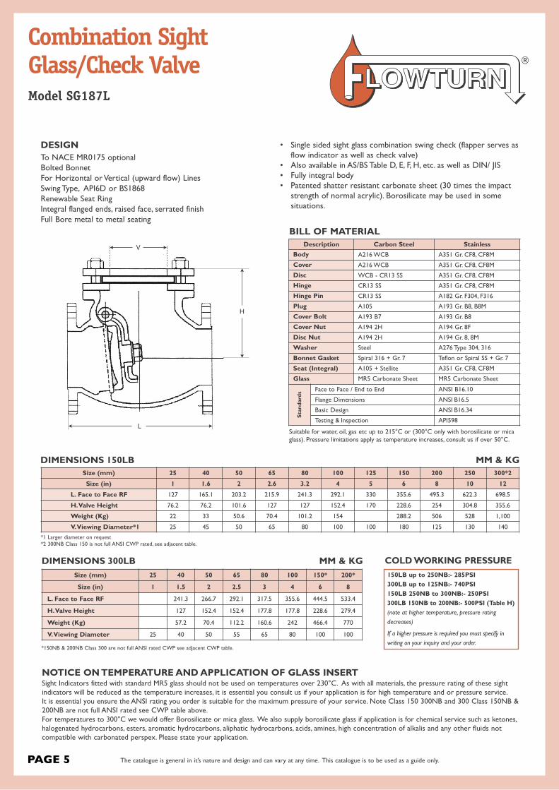
Combination SightGlass/Check ValveModel SG187L
PAGE 5
NOTICE ON TEMPERATURE AND APPLICATION OF GLASS INSERTSight Indicators fitted with standard MR5 glass should not be used on temperatures over 230°C. As with all materials, the pressure rating of these sightindicators will be reduced as the temperature increases, it is essential you consult us if your application is for high temperature and or pressure service.It is essential you ensure the ANSI rating you order is suitable for the maximum pressure of your service. Note Class 150 300NB and 300 Class 150NB &200NB are not full ANSI rated see CWP table above. For temperatures to 300°C we would offer Borosilicate or mica glass. We also supply borosilicate glass if application is for chemical service such as ketones,halogenated hydrocarbons, esters, aromatic hydrocarbons, aliphatic hydrocarbons, acids, amines, high concentration of alkalis and any other fluids notcompatible with carbonated perspex. Please state your application.
• Single sided sight glass combination swing check (flapper serves asflow indicator as well as check valve)
• Also available in AS/BS Table D, E, F, H, etc. as well as DIN/ JIS • Fully integral body• Patented shatter resistant carbonate sheet (30 times the impactstrength of normal acrylic). Borosilicate may be used in some situations.
DESIGNTo NACE MR0175 optionalBolted BonnetFor Horizontal or Vertical (upward flow) LinesSwing Type, API6D or BS1868Renewable Seat RingIntegral flanged ends, raised face, serrated finishFull Bore metal to metal seating
Description Carbon Steel StainlessBody A216 WCB A351 Gr. CF8, CF8M
Cover A216 WCB A351 Gr. CF8, CF8M
Disc WCB - CR13 SS A351 Gr. CF8, CF8M
Hinge CR13 SS A351 Gr. CF8, CF8M
Hinge Pin CR13 SS A182 Gr. F304, F316
Plug A105 A193 Gr. B8, B8M
Cover Bolt A193 B7 A193 Gr. B8
Cover Nut A194 2H A194 Gr. 8F
Disc Nut A194 2H A194 Gr. 8, 8M
Washer Steel A276 Type 304, 316
Bonnet Gasket Spiral 316 + Gr. 7 Teflon or Spiral SS + Gr. 7
Seat (Integral) A105 + Stellite A351 Gr. CF8, CF8M
Glass MR5 Carbonate Sheet MR5 Carbonate Sheet
Stan
dard
s Face to Face / End to End ANSI B16.10
Flange Dimensions ANSI B16.5
Basic Design ANSI B16.34
Testing & Inspection API598
Size (mm) 25 40 50 65 80 100 150* 200*
Size (in) 1 1.5 2 2.5 3 4 6 8
L. Face to Face RF 241.3 266.7 292.1 317.5 355.6 444.5 533.4
H. Valve Height 127 152.4 152.4 177.8 177.8 228.6 279.4
Weight (Kg) 57.2 70.4 112.2 160.6 242 466.4 770
V. Viewing Diameter 25 40 50 55 65 80 100 100
Size (mm) 25 40 50 65 80 100 125 150 200 250 300*2
Size (in) 1 1.6 2 2.6 3.2 4 5 6 8 10 12
L. Face to Face RF 127 165.1 203.2 215.9 241.3 292.1 330 355.6 495.3 622.3 698.5
H. Valve Height 76.2 76.2 101.6 127 127 152.4 170 228.6 254 304.8 355.6
Weight (Kg) 22 33 50.6 70.4 101.2 154 288.2 506 528 1,100
V. Viewing Diameter*1 25 45 50 65 80 100 100 180 125 130 140
BILL OF MATERIAL
Suitable for water, oil, gas etc up to 215°C or (300°C only with borosilicate or micaglass). Pressure limitations apply as temperature increases, consult us if over 50°C.
DIMENSIONS 150LB
DIMENSIONS 300LB150LB up to 250NB:- 285PSI300LB up to 125NB:- 740PSI150LB 250NB to 300NB:- 250PSI300LB 150NB to 200NB:- 500PSI (Table H)(note at higher temperature, pressure rating
decreases)
If a higher pressure is required you must specify in
writing on your inquiry and your order.
COLD WORKING PRESSURE
*1 Larger diameter on request*2 300NB Class 150 is not full ANSI CWP rated, see adjacent table.
*150NB & 200NB Class 300 are not full ANSI rated CWP see adjacent CWP table.
H
V
L
MM & KG
MM & KG
The catalogue is general in it’s nature and design and can vary at any time. This catalogue is to be used as a guide only.

Cast Iron or rubber lined cast iron body, semi flexible disc swing check.
FLANGES:- Connecting dimensions & thickness toANSI(ASA)/BS/DIN specifications.
FEATURESSimple three parts design, with only one moving part. Disc, absolutely100% leak tight, 0.035 bar back pressure. Full bore design for minimumflow turbulence. Flap also serves as gasket seal between body and endpiece. Valve usable in vertical or horizontal plane. Down time is kept toa minimum as the flap can easily be replaced in minutes.
Rubber lining specification according to flow medium & working temperature.Cast on flow direction arrow ensures correct installation.When placing order, please specify flow medium, working pressure and working temperature.Not recommended for use under vacuum pressure.
RANGE OF APPLICATION
Size MM Pressure RatingBar
Hyd. test pressure in bar for
Body Seat
15 - 350 7.0 10.5 7.7
MATERIAL LISTPart Name Material
Body/End Piece Cast Iron IS: 210Gr. FG. 260 with hard/soft rubber lining
Disc (or flap) Steel reinforced plate duly rubber lined. Available in neoprene,viton, teflon etc.
Connecting bolts/nuts Steel IS: 1367, Gr. 4.6/4
Valve Surface protectionPrime coat: chlorine-free with modified alkyd resin, unobjectable in physiological and toxycological respects. Additional external coating: machine varnish
Linings Available Food grade, halar, hard rubber, teflon etc.
DIMENSIONS
Sizemm
Face to Face Dimensions A
Overall Dimensions B Weight
approx. kg.Unlined
mmRubber Lined
mm mm
25 144 150 124 4.0
40 174 180 144 7.0
50 194 200 166 8.5
65 234 240 220 14.0
80 254 260 220 20.0
100 292 300 270 34.0
150 392 400 322 56.0
200 492 500 396 103.0
250 590 600 500 190.0
300 690 700 554 310.0
A
B
Check Valve (Non-Return) Type ‘N’
PAGE 6 The catalogue is general in it’s nature and design and can vary at any time. This catalogue is to be used as a guide only.

Cast Iron or rubber lined cast iron body, semi flexible disc swing check.Flow reversal of plus 0.35 bar
FLANGES:- Connecting dimensions & thickness toANSI(ASA)/BS/DIN specifications.
FEATURESSimple three parts design, with only one moving part. Disc, absolutely100% leak tight, 0.035 bar back pressure. Full bore design for minimumflow turbulence. Flap also serves as gasket seal between body and endpiece. Valve usable in vertical or horizontal plane. Down time is kept toa minimum as the flap can easily be replaced in minutes.
Rubber lining specification according to flow medium & working temperature.Cast on flow direction arrow ensures correct installation.When placing order, please specify flow medium, working pressure and working temperature.Not recommended for use under vacuum pressure.
RANGE OF APPLICATION
Size MM Pressure RatingBar
Hyd. test pressure in bar for
Body Seat
25 - 350 7.0 10.5 7.7
MATERIAL LIST
Part Name Material
Body/End Piece Cast Iron IS: 210 Gr. FG. 260 with hard/soft rubber lining
Disc (or flap) Steel reinforced plate duly rubber lined. Available in neoprene,viton, teflon etc. Grade “B” Butyl is standard.
Connecting bolts/nuts Steel IS: 1367, Gr. 4.6/4
Valve Surface protection Prime coat: chlorine-free with modified alkyd resin. Additional external coating: machine varnish
Linings Available Food grade, halar, hard rubber, teflon etc.
DIMENSIONS
Sizemm
Face to Face Dimensions A
Overall Dimensions B Weight
approx. kg.Unlined
mmRubber Lined
mm mm
25 144 157 124 4.0
40 174 186 149 7.0
50 194 204 162 8.5
65 234 244 216 14.0
80 254 265 216 20.0
100 292 356 295 34.0
150 392 406 327 56.0
200 492 396 103.0
250 590 500 190.0
300 690 554 310.0
Check Valve (Non-Return) Type ‘NX’
PAGE 7
A
B
The catalogue is general in it’s nature and design and can vary at any time. This catalogue is to be used as a guide only.
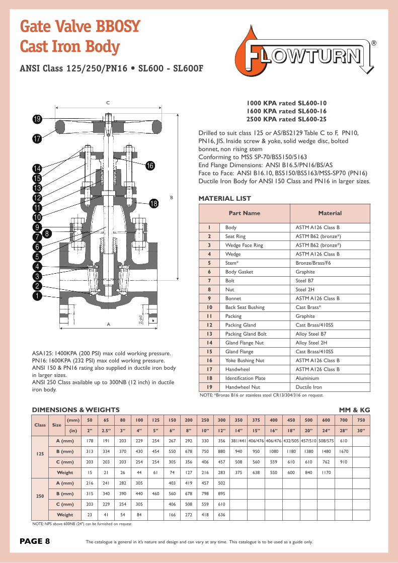
Gate Valve BBOSY Cast Iron BodyANSI Class 125/250/PN16 • SL600 - SL600F
1000 KPA rated SL600-101600 KPA rated SL600-162500 KPA rated SL600-25
Drilled to suit class 125 or AS/BS2129 Table C to F, PN10,PN16, JIS. Inside screw & yoke, solid wedge disc, bolted bonnet, non rising stemConforming to MSS SP-70/BS5150/5163End Flange Dimensions: ANSI B16.5/PN16/BS/ASFace to Face: ANSI B16.10, BS5150/BS5163/MSS-SP70 (PN16)Ductile Iron Body for ANSI 150 Class and PN16 in larger sizes.
MATERIAL LIST
NOTE: *Bronze B16 or stainless steel CR13/304/316 on request.
NOTE: NPS above 600NB (24") can be furnished on request
DIMENSIONS & WEIGHTS MM & KG
Part Name Material
1 Body ASTM A126 Class B
2 Seat Ring ASTM B62 (bronze*)
3 Wedge Face Ring ASTM B62 (bronze*)
4 Wedge ASTM A126 Class B
5 Stem* Bronze/Brass/F6
6 Body Gasket Graphite
7 Bolt Steel B7
8 Nut Steel 2H
9 Bonnet ASTM A126 Class B
10 Back Seat Bushing Cast Brass*
11 Packing Graphite
12 Packing Gland Cast Brass/410SS
13 Packing Gland Bolt Alloy Steel B7
14 Gland Flange Nut Alloy Steel 2H
15 Gland Flange Cast Brass/410SS
16 Yoke Bushing Nut ASTM A126 Class B
17 Handwheel ASTM A126 Class B
18 Identification Plate Aluminium
19 Handwheel Nut Ductile Iron
Class Size(mm) 50 65 80 100 125 150 200 250 300 350 375 400 450 500 600 700 750
(in) 2” 2.5” 3” 4” 5” 6” 8” 10” 12” 14” 15” 16” 18” 20” 24” 28” 30”
125
A (mm) 178 191 203 229 254 267 292 330 356 381/441 406/476 406/476 432/505 457/510 508/575 610
B (mm) 313 334 370 430 454 550 678 750 880 940 950 1080 1180 1380 1480 1670
C (mm) 203 203 203 254 254 305 356 406 457 508 560 559 610 610 762 910
Weight 15 21 26 44 61 74 127 216 283 375 638 550 600 840 1170
250
A (mm) 216 241 282 305 403 419 457 502
B (mm) 315 340 390 440 460 560 678 798 895
C (mm) 203 229 254 305 406 508 559 610
Weight 23 41 54 84 166 272 418 636
ASA125: 1400KPA (200 PSI) max cold working pressure.PN16: 1600KPA (232 PSI) max cold working pressure.ANSI 150 & PN16 rating also supplied in ductile iron body in larger sizes.ANSI 250 Class available up to 300NB (12 inch) in ductileiron body.
PAGE 8
Z-ø
d
C
B
A
The catalogue is general in it’s nature and design and can vary at any time. This catalogue is to be used as a guide only.
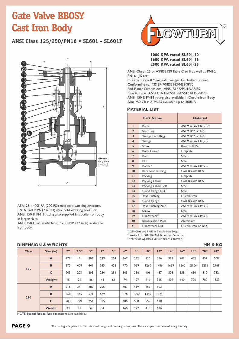
Gate Valve BBOSYCast Iron BodyANSI Class 125/250/PN16 • SL601 - SL601F
NOTE: Special face to face dimensions also available.
DIMENSION & WEIGHTS MM & KG
MATERIAL LIST
Part Name Material
1 Body ASTM A126 Class B*1
2 Seat Ring ASTM B62 or F6*2
3 Wedge Face Ring ASTM B62 or F6*2
4 Wedge ASTM A126 Class B
5 Stem Bronze/410SS
6 Body Gasket Graphite
7 Bolt Steel
8 Nut Steel
9 Bonnet ASTM A126 Class B
10 Back Seat Bushing Cast Brass/410SS
11 Packing Graphite
12 Packing Gland Cast Brass/410SS
13 Packing Gland Bolt Steel
14 Gland Flange Nut Steel
15 Yoke Bushing Ductile Iron
16 Gland Flange Cast Brass/410SS
17 Yoke Bushing Nut ASTM A126 Class B
18 Screw Steel
19 Handwheel*3 ASTM A126 Class B
20 Identification Plate Aluminium
21 Handwheel Nut Ductile Iron or B62
Class Size (in) 2” 2.5” 3” 4” 5” 6” 8” 10” 12” 14” 16” 18” 20” 24”
125
A 178 191 203 229 254 267 292 330 356 381 406 432 457 508
B 375 408 441 545 656 770 959 1260 1486 1689 1860 2106 2295 2768
C 203 203 203 254 254 305 356 406 457 508 559 610 610 762
Weight 15 21 26 44 61 74 127 216 315 409 640 726 782 1353
250
A 216 241 282 205 403 419 457 502
B 368 445 521 629 876 1092 1340 1524
C 203 229 254 305 406 508 559 610
Weight 23 41 54 84 166 272 418 636
ANSI Class 125 or AS/BS2129 Table C to F as well as PN10,PN16, JIS etc. Outside screw & Yoke, solid wedge disc, bolted bonnet.Conforming to MSS SP-70/BS5163/MSS-SP70.End Flange Dimensions: ANSI B16.5/PN16/AS/BS.Face to Face: ANSI B16.10/BS5150/BS5163/MSS-SP70.ANSI 150 & PN16 rating also available in Ductile Iron Body.Also 250 Class & PN25 available up to 300NB.
*1 250 Class and PN25 is Ductile Iron Body.*2 Available in 304, 316, 410, Bronze or Brass trim*3 For Gear Operated version refer to drawing.
PAGE 9
C
B
A
1000 KPA rated SL601-101600 KPA rated SL601-162500 KPA rated SL601-25
ASA125: 1400KPA (200 PSI) max cold working pressure.PN16: 1600KPA (232 PSI) max cold working pressure.ANSI 150 & PN16 rating also supplied in ductile iron body in larger sizes.ANSI 250 Class available up to 300NB (12 inch) in ductileiron body.
The catalogue is general in it’s nature and design and can vary at any time. This catalogue is to be used as a guide only.
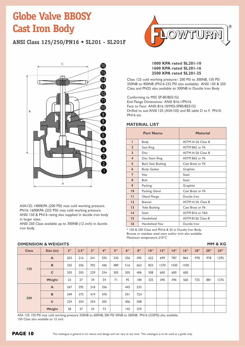
Globe Valve BBOSY Cast Iron BodyANSI Class 125/250/PN16 • SL201 - SL201F
MATERIAL LIST
* 150 & 250 Class and PN16 & 25 in Ductile Iron Body.Bronze or stainless steel stem and/or trim also available.Maximum temperature 210°C
ASA 125: 150 PSI max cold working pressure 350NB to 600NB, 200 PSI 50NB to 300NB. PN16 (232PSI) also available.150 Class also available to 12 inch.
DIMENSION & WEIGHTS MM & KGClass Size (in) 2” 2.5” 3” 4” 5” 6” 8” 10” 12” 14” 16” 18” 20” 24”
125
A 203 216 241 292 330 356 495 622 699 787 864 978 978 1295
B 335 356 392 446 489 516 663 832 1270 1430 1430
C 203 203 229 254 305 305 406 508 600 600 600
Weight 23 27 34 54 71 95 180 325 340 396 560 725 881 1276
250
A 267 292 318 356 445 533
B 349 375 419 470 591 724
C 229 254 254 305 406 508
Weight 28 37 54 73 145 259
Part Name Material
1 Body ASTM A126 Class B
2 Seat Ring ASTM B62 or F6
3 Disc ASTM A126 Class B
4 Disc Stem Ring ASTM B62 or F6
5 Back Seat Bushing Cast Brass or F6
6 Body Gasket Graphite
7 Nut Steel
8 Bolt Steel
9 Packing Graphite
10 Packing Gland Cast Brass or F6
11 Gland Flange Ductile Iron
12 Bonnet ASTM A126 Class B
13 Yoke Bushing Cast Brass or F6
14 Stem ASTM B16 or F6A
15 Handwheel ASTM B126 Class B
16 Handwheel Nut Ductile Iron
Class 125 cold working pressure:- 200 PSI to 300NB, 150 PSI350NB to 400NB (PN16-232 PSI also available). ANSI 150 & 250Class and PN25 also available to 300NB in Ductile Iron Body
Conforming to MSS SP-85/BS5152End Flange Dimensions: ANSI B16.1/PN16Face to Face: ANSI B16.10/MSS-SP85/BS5152Drilled to suit ANSI 125 (ASA150) and BS table D to F, PN10,PN16 etc
PAGE 10
C
B
A
1000 KPA rated SL201-101600 KPA rated SL201-162500 KPA rated SL201-25
ASA125: 1400KPA (200 PSI) max cold working pressure.PN16: 1600KPA (232 PSI) max cold working pressure.ANSI 150 & PN16 rating also supplied in ductile iron body in larger sizes.ANSI 250 Class available up to 300NB (12 inch) in ductileiron body.
The catalogue is general in it’s nature and design and can vary at any time. This catalogue is to be used as a guide only.

Bonnet AssemblyThe compressor & sprindle designgives a long travel sufficient tocontact the valve body seat & to liftthe diaphragm up into the bonnetto provide total clearance of thepipeline.DiaphragmSpecially shaped to achieveleaktight seat against valve wall.BodyAllows greater flow and is suitablefor rodding through.
WEIR TYPE DIAPHRAGMVALVE (A)The Weir Type Valve offers smooth flowand simple operation in any position. Parts fully interchange with Saundersand dimensions are the same. Its designprovides extra-long diaphragm life forthrottling and positive shut-off services.Hygenic style also available.
STRAIGHT THRUDIAPHRAGM VALVE (KB)Straight Thru Valves efficiently handleabrasive and corrosive slurries, thickcoagulating fluids, and a wide varietyof suspended solid materials.
Size Range: Pressure Range:15mm to 350mm. Vacuum to 690 kPa.
Temperature Range:-40ºC to 121ºC.
Body Materials and Linings:Cast Iron, Hard Rubber, Soft Rubber, Neoprene, Glass
FlangingsBST C-F, 125 ASA
Straight through typeThe body design offers minimum friction, no turbulence and issuitable for sludge and slurry pressure gases.
Size Range: 8mm to 350mm.
Temperature Range: -45ºC to 171ºC.
Body Linings:Hard Rubber, Soft Rubber,Neoprene, Glass,Polypropylene, Halar andPVDF
Weir TypeThe body of which gives a smooth pocketless flow and featureslow pressure drop. Suitable for high line pressure duties and isavailable in a range of trims & materials for gases and liquids.
Pressure Range:to 1580 kPa.
Body Materials:Cast Iron, Ductile Iron,Bronze, Aluminium andStainless Steel
FlangingsBST C-F, 125 ASA
Bonnet AssemblyContains a compressor which supports the diaphragm at all stagesof travel
DiaphragmSpecially shaped to achieve leak tight seat against wall.
FLOW PATH
FLOW PATH
STRAIGHT THRU TYPE
Weir Type
Stud(screw or bayonet fitting tocompressor)
Optional PTFE face
Weir form reduces diaphragm travel
DIMENSIONS WEIR & STRAIGHT THRU (KB)Valve Size (DN)
A
B H
A Type KB Type
Unlined Lined WeirWeight Kg
StraightThru
Weight Kg6 - - 70 70 - -
10 - - 70 70 - -
15 108 114 77 70 1.9 1.6
20 117 123 84 70 2.1 1.9
25 127 133 96 100 2.8 3.1
32 146 152 104 100 3.4 3.3
40 159 165 135 140 4.6 4.4
50 190 196 147 140 6.8 8.1
65 216 222 166 140 8.7 9
80 254 260 214 225 11.5 12.3
100 305 313 236 225 19.5 19
125 356 364 269 310 28.6 25.5
150 406 414 325 368 38.6 35
200 521 529 442 471 69 63
225 - - - - 93 -
250 635 645 524 587 117 106
300 749 759 624 690 170 145
350 749 759 810 690 211 238
Diaphragm Valve Weir (A)& Straight Thru (KB)
PAGE 11 The catalogue is general in it’s nature and design and can vary at any time. This catalogue is to be used as a guide only.

PAGE 12
PULP - CHEMICAL - PAPER - CHEMICAL - PETROLEUMPROCESS - POWER - SEWERAGE - MININGAvailable to suit 125LB, PN10, PN16 and AS/BS Table D/E
DESIGN FEATURES (All types)
BODY• Low Maintenance
GATE• Flat edge on resilient seated valves and bevelled edge on
metal seated valves.
METAL SEAT DESIGN• Fully in field replaceable seat insert• Uni-directional flow• Heavy bevelled gate cuts through solids and slurries
and cleans as it closes.• Line pressure further assists sealing of gate and seal.
PTFE SEAT DESIGN• Fully in field replaceable seat insert.• Uni directional flow.• Bubble tight shut off available.
RESILIENT SEAT DESIGN• Fully in field replaceable seat insert.• Uni directional flow.• Drip tight shut off.• Bi-directional flow, Viton, EDDM, NBR and EPDM available.• Sealing is affected between the gate and seat, no pressure
required for shut-off to occur.• Positively retained seat does not allow the seat to pull out or
move within the body.
SERVICEDC Series knifegate valves are linear shut off valves.These compact valves are available as manual with handwheel,or can be automated with a pneumatic cylinder actuator forremote operation. DC Series valves are ideal for manyapplications in process industries including Pulp & Paper,Wastewater Treatment, Mining, Sugar Making and ChemicalProcessing.
REPLACEABLE SEATSSeats in the DC Series knife gate valves are backed with an o-ring to give the seat a self-compensating wear function. This results in excellent seat tightness and prolonged life cycle.When seats do wear and need replacement, maintenance tochange the seats is easy and quick. Available seat materialsinclude metal seated, EPDM seated, and PTFE seated.
GATE DESIGNEach gate is precision ground and hard Chrome plated as astandard. This provides superior abrasion and corrosionresistance. The arc shape design of the bottom of the gate isparticularly suitable to provide strong cutting force for pulp andsuspended particulates in media.
GUIDING WEDGESGuiding wedges are point-located at the valve outlet, providingfor a groove-free and smooth port. This reduces clogging ormaterial build-up.
EXTERNAL PACKINGPacking gland and packing are externally located, so packingcan be adjusted or replaced without removing the valve fromthe pipeline.
DOUBLE STEM BEARINGSAt the top of the yoke, our knife gate valves are equipped withtwo stem bearings for reduced torque and easy operation.
PORT SHAPE OPTIONCustom port shapes including V-port, triangle port, and hexagonport are available. Full through conduit “O” Port design is also available.
FULL CONDUIT O-PORTAlso full through conduit ‘O’ Port design is available.
Knife Gate ValveDC SeriesOverview
The catalogue is general in it’s nature and design and can vary at any time. This catalogue is to be used as a guide only.

TECHNICAL PARAMETERS
Nominal Diameter: 2” (DN50) through 48” (DN1200)Nominal Pressure Rating: ANSI 150, PN10, PN16Connection Type: Wafer pattern fully lugged.Temperature: Metal Seat -20ºC to 230ºC, PTFE Seat -20ºC to 120ºC, EPDM Seat -20ºC to 100ºCApplicable Medium: Pulp, sewage, coal slurry, syrup, slag.Leakage: As per the MSS SP-61 standard, the maximum allowable leakage of metalseated knife gate valves is 40 ml/min/in. For PTFE seated knife gate valves, the maxi-mum leakage is 4 ml/min/in. EPDM, Viton and NBR seated are all drip tight shut off.
Metal Seat
No. Part Name Temperature
1 Body
-20°C to 230°C
2 Retainer
3 O-ring
4 Seat
5 Gate
PTFE Seat
No. Part Name Temperature
1 Body
-20°C to 120°C
2 Retainer
3 O-Ring
4 Seat
5 PTFE
6 Gate
EPDM Seat
No. Part Name Temperature
1 Body
-20°C to 230°C
2 Retainer
3 O-ring
4 Seat
5 Gate
SEAT CONSTRUCTION
PAGE 13
Knife Gate ValveDC SeriesOverview
1 2 3 4 5
1 2 3 4 5 6
1 2 3 4 5
The catalogue is general in it’s nature and design and can vary at any time. This catalogue is to be used as a guide only.

No. Name Qty(Pcs) Material
1 Body 1 WCB, CF8, CF8M
2 Gate 1 SS410, SS304, SS316 + hard Chrome plating
3 Guiding Wedge 1 CF8, CF8M
4 O-Ring 1 NBR, Viton, EPDM
5 Seat 1 SS304, SS316 + hard Chrome plating, PTFE,EPDM
6 O-Ring 1 NBR, Viton, EPDM
7 Retainer 1 Q235, SS304, SS316
8 Socket Head Screw SS304, SS316
9 Packing 1 set PTFE, Graphite
10 Gland 1 WCB, CF8, CF8M
11 Connection Pin 1 SS304, SS316
12 Pillar 4 45# hard Chrome plating, SS304
13 Hexagon Nut 4 Q235, SS304
14 Hexagon Bolt 2 Q235, SS304
15 Hexagon Nut 2 Q235, SS304
16 Screw Rod 1 SS410
17 Nut 1 H59
18 Square Plate 1 WCB
19 Plane Bearing 2 GCr6
20 Flat Key 1 45#
21 Handwheel 1 WCB
22 Nut 1 45# anti-corrosion treated
PAGE 14
22
21
20
19
18
17
16
15
14
3
2
1
13
12
11
10
9
8 7 6 5 4
The catalogue is general in it’s nature and design and can vary at any time. This catalogue is to be used as a guide only.
Knife Gate ValveDC SeriesBill of Materials
MATERIALS LIST
Example only. Refer to as built drawing.

Body Parts
No. Name Qty(Pcs) Material
1 Body 1 WCB, CF8, CF8M
2 Gate 1 SS410, SS304, SS316 + hard Chrome plating
3 Guiding Wedge 1 CF8, CF8M
4 O-Ring 1 NBR, Viton, EPDM
5 Seat 1SS304, SS316 hard Chrome plating,
PTFE, EPDM
6 O-Ring 1 NBR, Viton, EPDM
7 Retainer 1 Q235, SS304, SS316
8 Socket Head Screw SS304, SS316
9 Packing 1 set PTFE, Graphite
10 Gland 1 WCB, CF8
11 Pillar 4 45# hard Chrome plating, SS304
12 Hexagon Nut 4 Q235, SS304
13 Hexagon Bolt 2 Q235, SS304
14 Hexagon Nut 2 Q235, SS304
15 Connection Pin 1 SS304
16 Connection Rod 1 45# hard Chrome plating, SS304
17 Connection Pin 1 SS304
Actuator Parts
No. Name Qty(Pcs) Material
18 Lower Cylinder Cover 1 WCB
19 O-Ring 1 NBR, EPDM
20 Cylinder 1Aluminium alloy with inner face PTFEcoated or Q235 hard Chrome plating
21 Washer 1 SS304
22 Hexagon Bolt 1 Q235
23 Connection Rod 1 45# Zinc plating
24 Nut 1 Q235 hard Chrome plating
25 Bushing 1 Composite material
26 Y-Ring 1 TPU (Polyurethane)
27 Piston Rod 1 45# hard Chrome plating
28 O-Ring 1 NBR, EPDM
29 Piston 1 ZL102, Q235
30 Guiding Ring 1 Reinforced PTFE
31 Gasket 1 PTFE
32 Hexagon Nut 1 Q235
33 Adjusting Bolt 1 Q235
34 Upper Cylinder Cover 1 WCB
PAGE 15
3029
2827
2625
12
11
10
9
8
7
6
5
4
1 2 3
13
14
15
1617
18
1920
21
2223
24
31
32
33
34
The catalogue is general in it’s nature and design and can vary at any time. This catalogue is to be used as a guide only.
Knife Gate ValveDC SeriesBill of Materials
MATERIALS LIST
Example only. Refer to as built drawing.

No. Description Material
1 Cap Carbon Steel
2 Tie Rod Plated Steel
3 Casing Carbon Steel
4 Piston Carbon Steel
5 Rod Seal Nitrile or Viton
6 Wear Ring Nylon
7 Seal Nitrile or Viton
8 Rod Hard Chromed Steel
9 Piston Bushing Gunmetal
10 Top Flange Carbon Steel
11 Cap Carbon Steel
12 Lower Seals Nitrile
13 Fasteners 316 S/S or B7
Pneumatic Actuator(Double Acting)
Temperature Rating:Minus 30°C to 70°C
Pressure Rating:300kPa to 700kPa Max
1
2
3
45
7
8
9
1011
12
13
6
Knife Gate ValveDC SeriesBill of Materials
MATERIALS LIST
PAGE 16 The catalogue is general in it’s nature and design and can vary at any time. This catalogue is to be used as a guide only.
Example only. Refer to as built drawing.

Dimensions (mm)
DN (inch) L D0 H1 Full Closed H2 Full Open
2” 48 200 290 350
3” 51 220 350 430
4” 51 220 436 535
5” 57 220 460 585
6” 57 280 510 660
8” 70 280 610 810
10” 70 280 765 1015
12” 76 380 820 1120
14” 76 450 970 1320
16” 89 500 1024 1424
18” 89 600 1235 1685
20” 114 600 1286 1786
24” 114 680 1235 1685
PAGE 17
H2
H1
D0
N-Th
D1
L
Knife Gate ValveDC SeriesDimensions
DIMENSIONS DC SERIES (HANDWHEEL OPERATED)
The catalogue is general in it’s nature and design and can vary at any time. This catalogue is to be used as a guide only.
Example only. Refer to as built drawing.

Dimensions (mm)
Size DN Equivalent (mm) L N R Q P
8” 200 70 964 200 310 650
10” 250 70 1064 200 310 800
12” 300 76 1210 260 310 860
14” 350 76 1563 260 310 1010
16” 400 89 1660 260 460 1150
18” 450 89 1810 260 460 1305
20” 500 114 1900 340 460 1420
24” 600 114 2100 340 460 1660
28” 700 130 2650 480 460 1950
32” 800 130 2900 480 460 2200
36” 900 140 3200 480 460 2400
40” 1000 140 3600 500 460 2610
PAGE 18
R
Q
N
P
L
The catalogue is general in it’s nature and design and can vary at any time. This catalogue is to be used as a guide only.
Knife Gate ValveDC SeriesDimensions
DIMENSIONS DC SERIES (GEAR OPERATED)
Example only. Refer to as built drawing.

DCA/DCB DCA/DCB DCA Non Rising Stem DCB Bonneted
Size DN Equivalent(mm) L D H D1 H1
2” 50 48 180 300 180 330
2-1/2” 65 48 180 310 180 360
3” 80 51 220 373 180 390
4” 100 51 240 420 220 440
5” 125 57 260 460 240 510
6” 150 57 280 510 260 600
8” 200 70 300 610 280 700
10” 250 70 340 765 300 840
12” 300 76 380 820 340 960
14” 350 76 400 970 380 1100
16” 400 89 450 1024 400 1250
18” 450 89 530 1235 450 1380
20” 500 114 600 1286 530 1530
DCA Non-Rising stem DCB Non-Rising gate(Bonneted)
PAGE 19
D
D1
H1
H
L
The catalogue is general in it’s nature and design and can vary at any time. This catalogue is to be used as a guide only.
Knife Gate ValveDC SeriesDimensions
DIMENSIONS DCA/DCB SERIES
Example only. Refer to as built drawing.

Size DN Equivalent (mm) L ØB N H
2” 50 48 160 120 430
2-1/2” 65 48 180 120 465
3” 80 51 200 120 592
4” 100 51 216 120 640
5” 125 57 245 145 715
6” 150 57 280 145 811
8” 200 70 340 180 955
10” 250 70 405 225 1200
12” 300 76 460 275 1322
14” 350 76 500 330 1537
16” 400 89 540 330 1805
18” 450 89 632 380 2200
20” 500 114 690 380 2600
24” 600 114 795 425 2960
PAGE 20
N
H
LØB
The catalogue is general in it’s nature and design and can vary at any time. This catalogue is to be used as a guide only.
Knife Gate ValveDC SeriesDimensions
DIMENSIONS DC SERIES ACTUATED
Example only. Refer to as built drawing.

Flow rate (m3/h) for standard passage - Head loss
DNmm
Valve head losses (bar)
0.2 0.4 0.6 0.8 1
50 93 134 165 185 206
65 129 180 216 268 309
80 191 309 371 422 494
100 443 618 721 824 927
125 700 927 1133 1339 1545
150 927 1339 1545 1906 2060
200 1597 2369 2987 3399 4017
250 2472 3502 4429 5150 5665
300 4120 5665 6798 7828 8755
350 5335 7372 8730 9700 11640
400 6693 9312 11640 13580 15520
450 8342 12610 14550 16490 18430
500 9700 14550 17460 19400 22310
600 14550 19400 25220 29100 33950
700 17460 29100 36860 42680 48500
800 25220 38800 48500 52380 58200
900 34920 50440 61110 67900 77600
1000 46560 62080 77600 87300 97000
1200 62080 87300 106700 121250 145500
Flow rate (m3/h) with deflection cones - Head loss
DNmm
Valve head losses (bar)
0.2 0.4 0.6 0.8 1
50 33 47 58 66 72
65 54 74 93 101 118
80 72 95 124 139 165
100 144 185 247 288 330
125 206 319 412 464 525
150 340 464 577 628 721
200 639 876 1030 1236 1442
250 876 1288 1545 1648 1957
300 1236 1751 2060 2575 3090
350 1455 2037 2910 3104 3783
400 2231 3492 4365 4947 4656
450 3201 4850 5529 6208 7275
500 4074 5820 7178 7954 9215
600 5820 7760 9312 11155 12610
KV Value
DN (mm) 50 65 80 100 125 150 200 250 300 350 400 450 500 600 700 800 900 1000 1200
Standard 206 309 494 927 1545 2060 4017 5665 8755 11640 15520 18430 22310 33950 48500 58200 77600 97000 145500
Deflector “V” cone 72 118 165 330 525 721 1442 1957 3090 3783 4656 7275 9215 12610 - - - - -
PAGE 21 The catalogue is general in it’s nature and design and can vary at any time. This catalogue is to be used as a guide only.
Knife Gate ValveDC SeriesFlow Rates
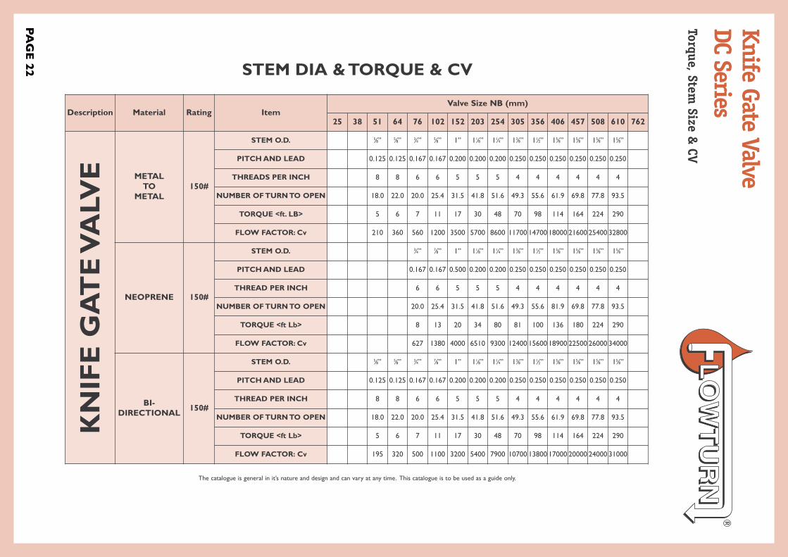
Description Material Rating ItemValve Size NB (mm)
25 38 51 64 76 102 152 203 254 305 356 406 457 508 610 762
KN
IFE G
AT
E V
ALV
E METAL TO
METAL150#
STEM O.D. 5⁄8” 5⁄8” 3⁄4” 5⁄8” 1” 11⁄8” 11⁄4” 13⁄8” 11⁄2” 15⁄8” 15⁄8” 15⁄8” 15⁄8”
PITCH AND LEAD 0.125 0.125 0.167 0.167 0.200 0.200 0.200 0.250 0.250 0.250 0.250 0.250 0.250
THREADS PER INCH 8 8 6 6 5 5 5 4 4 4 4 4 4
NUMBER OF TURN TO OPEN 18.0 22.0 20.0 25.4 31.5 41.8 51.6 49.3 55.6 61.9 69.8 77.8 93.5
TORQUE <ft. LB> 5 6 7 11 17 30 48 70 98 114 164 224 290
FLOW FACTOR: Cv 210 360 560 1200 3500 5700 8600 11700 14700 18000 21600 25400 32800
NEOPRENE 150#
STEM O.D. 3⁄4” 7⁄8” 1” 11⁄8” 11⁄4” 13⁄8” 11⁄2” 15⁄8” 15⁄8” 15⁄8” 15⁄8”
PITCH AND LEAD 0.167 0.167 0.500 0.200 0.200 0.250 0.250 0.250 0.250 0.250 0.250
THREAD PER INCH 6 6 5 5 5 4 4 4 4 4 4
NUMBER OF TURN TO OPEN 20.0 25.4 31.5 41.8 51.6 49.3 55.6 81.9 69.8 77.8 93.5
TORQUE <ft Lb> 8 13 20 34 80 81 100 136 180 224 290
FLOW FACTOR: Cv 627 1380 4000 6510 9300 12400 15600 18900 22500 26000 34000
BI-DIRECTIONAL 150#
STEM O.D. 5⁄8” 5⁄8” 3⁄4” 7⁄8” 1” 11⁄8” 11⁄4” 13⁄8” 11⁄2” 15⁄8” 15⁄8” 15⁄8” 15⁄8”
PITCH AND LEAD 0.125 0.125 0.167 0.167 0.200 0.200 0.200 0.250 0.250 0.250 0.250 0.250 0.250
THREAD PER INCH 8 8 6 6 5 5 5 4 4 4 4 4 4
NUMBER OF TURN TO OPEN 18.0 22.0 20.0 25.4 31.5 41.8 51.6 49.3 55.6 61.9 69.8 77.8 93.5
TORQUE <ft Lb> 5 6 7 11 17 30 48 70 98 114 164 224 290
FLOW FACTOR: Cv 195 320 500 1100 3200 5400 7900 10700 13800 17000 20000 24000 31000
STEM DIA & TORQUE & CV
PAG
E 22
The catalogue is general in it’s nature and design and can vary at any time. This catalogue is to be used as a guide only.
Knife Gate ValveDC SeriesTorque, Stem
Size & CV
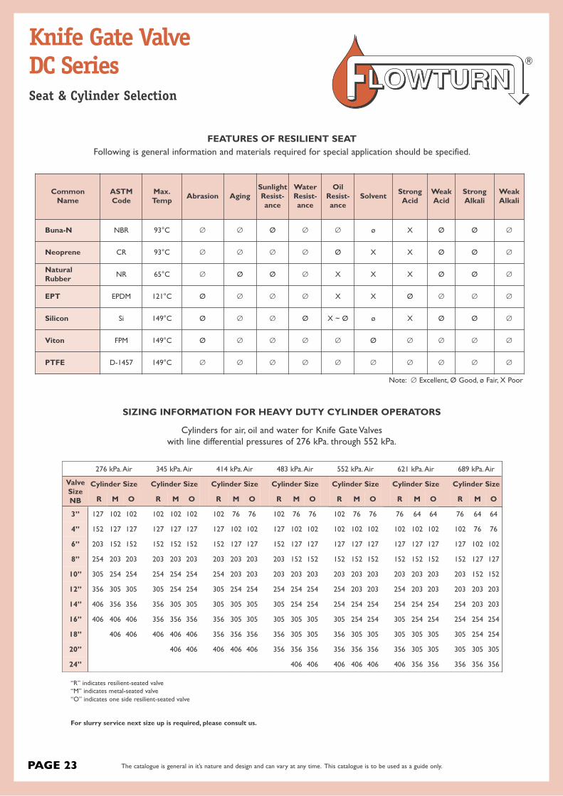
Common Name
ASTMCode
Max.Temp Abrasion Aging
SunlightResist-ance
WaterResist-ance
Oil Resist-ance
Solvent StrongAcid
WeakAcid
StrongAlkali
WeakAlkali
Buna-N NBR 93°C Ø Ø Ø Ø Ø ø X Ø Ø Ø
Neoprene CR 93°C Ø Ø Ø Ø Ø X X Ø Ø Ø
Natural Rubber NR 65°C Ø Ø Ø Ø X X X Ø Ø Ø
EPT EPDM 121°C Ø Ø Ø Ø X X Ø Ø Ø Ø
Silicon Si 149°C Ø Ø Ø Ø X ~ Ø ø X Ø Ø Ø
Viton FPM 149°C Ø Ø Ø Ø Ø Ø Ø Ø Ø Ø
PTFE D-1457 149°C Ø Ø Ø Ø Ø Ø Ø Ø Ø Ø
Note: Ø Excellent, Ø Good, ø Fair, X Poor
FEATURES OF RESILIENT SEATFollowing is general information and materials required for special application should be specified.
SIZING INFORMATION FOR HEAVY DUTY CYLINDER OPERATORS
Cylinders for air, oil and water for Knife Gate Valveswith line differential pressures of 276 kPa. through 552 kPa.
276 kPa. Air 345 kPa. Air 414 kPa. Air 483 kPa. Air 552 kPa. Air 621 kPa. Air 689 kPa. Air
ValveSizeNB
Cylinder Size Cylinder Size Cylinder Size Cylinder Size Cylinder Size Cylinder Size Cylinder Size
R M O R M O R M O R M O R M O R M O R M O
3” 127 102 102 102 102 102 102 76 76 102 76 76 102 76 76 76 64 64 76 64 64
4” 152 127 127 127 127 127 127 102 102 127 102 102 102 102 102 102 102 102 102 76 76
6” 203 152 152 152 152 152 152 127 127 152 127 127 127 127 127 127 127 127 127 102 102
8” 254 203 203 203 203 203 203 203 203 203 152 152 152 152 152 152 152 152 152 127 127
10” 305 254 254 254 254 254 254 203 203 203 203 203 203 203 203 203 203 203 203 152 152
12” 356 305 305 305 254 254 305 254 254 254 254 254 254 203 203 254 203 203 203 203 203
14” 406 356 356 356 305 305 305 305 305 305 254 254 254 254 254 254 254 254 254 203 203
16” 406 406 406 356 356 356 356 305 305 305 305 305 305 254 254 305 254 254 254 254 254
18” 406 406 406 406 406 356 356 356 356 305 305 356 305 305 305 305 305 305 254 254
20” 406 406 406 406 406 356 356 356 356 356 356 356 305 305 305 305 305
24” 406 406 406 406 406 406 356 356 356 356 356
“R” indicates resilient-seated valve “M” indicates metal-seated valve “O” indicates one side resilient-seated valve
For slurry service next size up is required, please consult us.
PAGE 23 The catalogue is general in it’s nature and design and can vary at any time. This catalogue is to be used as a guide only.
Knife Gate ValveDC SeriesSeat & Cylinder Selection
PAG
E 24
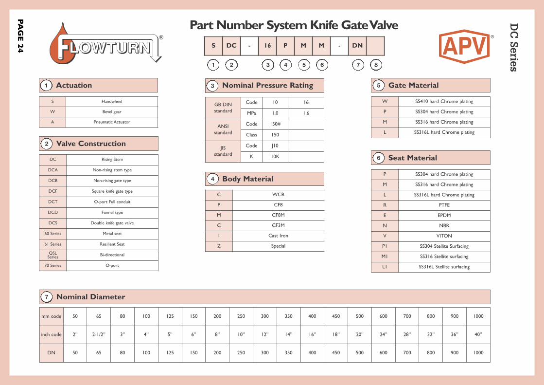
Part Number System Knife Gate Valve DC
Series®
S Handwheel
W Bevel gear
A Pneumatic Actuator
Actuation1
DC Rising Stem
DCA Non-rising stem type
DCB Non-rising gate type
DCF Square knife gate type
DCT O-port Full conduit
DCD Funnel type
DCS Double knife gate valve
60 Series Metal seat
61 Series Resilient Seat
QSLSeries Bi-directional
70 Series O-port
Valve Construction2
GB DIN standard
Code 10 16
MPa 1.0 1.6
ANSIstandard
Code 150#
Class 150
JISstandard
Code J10
K 10K
Nominal Pressure Rating3
C WCB
P CF8
M CF8M
C CF3M
I Cast Iron
Z Special
Body Material4
W SS410 hard Chrome plating
P SS304 hard Chrome plating
M SS316 hard Chrome plating
L SS316L hard Chrome plating
Gate Material5
P SS304 hard Chrome plating
M SS316 hard Chrome plating
L SS316L hard Chrome plating
R PTFE
E EPDM
N NBR
V VITON
P1 SS304 Stellite Surfacing
M1 SS316 Stellite surfacing
L1 SS316L Stellite surfacing
Seat Material6
Nominal Diameter7
mm code 50 65 80 100 125 150 200 250 300 350 400 450 500 600 700 800 900 1000
inch code 2” 2-1/2” 3” 4” 5” 6” 8” 10” 12” 14” 16” 18” 20” 24” 28” 32” 36” 40”
DN 50 65 80 100 125 150 200 250 300 350 400 450 500 600 700 800 900 1000
1 2 3 4 5 6 7 8
S DC - 16 P M M - DN

Notes

Notes

View the Stock List of our Master Distributor at www.globalsupplyline.com.au
AUSTRALIAN PIPELINE VALVE BRAND RANGE - CATALOGUES
APV FAMILY OF BRANDS RANGE - CATALOGUES
COMPLETE PRODUCT LINE
“Australian Pipeline
Valve produces isolation,
control and flow reversal
protection products
for severe and critical
service media in utility,
steam, pipelines,
oil and gas and
process industries.
APV valves and pipeline
products form the most
competitive portfolio
in the market.”
Gate, Globe & Check Valves - Forged Steel
Oilfield Products Valves & Wellheads
Plug Valves Lubricated, Sleeved & Lined
Gate, Globe & Check Valves - Cast
Diamond Gear Gearboxes
Flowturn Gate, Globe & Check Valves
Flowturn Instrument Valves
Flowturn Ball Valves Multiway & Deadman
Flowturn Strainers & Sight Glasses
Supercheck Wafer Check Valves
Superseal Butterfly Valves
Steamco Steam Valves
Superseal Industrial Ball Valves
TwinLok Tube Fittings Uniflo Check ValvesTorqturn Actuators
Ball Valves Floating & Trunnion Mounted
Ball Valves Floating Small Bore
Ball ValvesSpecial Service
Product Brochure
Download our catalogues at www.australianpipelinevalve.com.au
View our catalogues at www.australianpipelinevalve.com.au
AUSTRALIAN PIPELINE VALVE BRAND RANGE - CATALOGUES
APV FAMILY OF BRANDS RANGE - CATALOGUES
COMPLETE PRODUCT LINE
“Australian Pipeline Valve
produces isolation,
control and flow reversal
protection products for
severe and critical service
media in utility, steam,
pipelines, oil & gas
and process industries.
APV valves and pipeline
products form the most
competitive portfolio
in the market.”
Gate, Globe & Check Valves - Forged Steel
Oilfield Products Valves & Wellheads
Plug Valves Lubricated, Sleeved & Lined
Gate, Globe & Check Valves - Cast
Diamond Gear Gearboxes
Flowturn Gate, Globe & Check Valves
Flowturn Instrument Valves
Flowturn Ball Valves Multiway & Deadman
Flowturn Strainers & Sight Glasses
Supercheck Wafer Check Valves
Superseal Butterfly Valves
Steamco Steam Valves
Superseal Industrial Ball Valves
TwinLok Tube Fittings Uniflo Check ValvesTorqturn Actuators
Ball Valves Floating & Trunnion Mounted
Ball Valves Floating Small Bore
Ball ValvesSpecial Service
Product Brochure
Contact us for your local stockist/distributor

Quality assurance and certificationWe are continually improving all facets of quality assurance. Full metallurgical and test certificates are always supplied for all pressure retaining parts.
We have endeavoured to provide a broad outline of our range and capabilities. Because we are continually developing new products for our customers this catalogue will, to some extent be incomplete. This catalogue is a general overview only, individual drawings and data sheets can be furnished on request.
If you have any requirement in the field of valves, please contact us for a prompt response. Continuous development of Australian Pipeline Valve products may necessitate changes in the design or manufacturing processes. Australian Pipeline Valve reserves the right to effect any such changes without prior notice.
© Australian Pipeline Valve 1990 - 2013 Edition
LocaL Distributor
www.australianpipelinevalve.com.au
a D E L a i D E • b r i s b a N E • P E r t H