IRLED SELECTION G FOR Si114X PROXIMITY … radiant intensity is a measurement radiant flux per unit...
26
Rev. 0.1 1/15 Copyright © 2015 by Silicon Laboratories AN521 AN521 IR LED S ELECTION G UIDE FOR Si114 X P ROXIMITY A PPLICATIONS 1. Introduction There are numerous factors involved in choosing the proper irLED for any given system. This application note defines the technical requirements governing the choice of an irLED. Armed with this information, a design engineer can choose the least expensive, most appropriate irLED suitable for the intended application and usage. Specific irLED pricing information will not be discussed in this application note. An important factor in an irLED choice is the industrial design of the end product. As an example, a thru-hole irLED probably would be too tall for use inside a cell phone. Although this document occasionally touches some industrial design topics, they are generally outside the scope of this document. From time to time, some aspects of industrial design are mentioned, but only within the context of choosing an irLED. There are many shapes, sizes, and footprints for LEDs that primarily are derivatives of two types, SMD and thru- hole the standard T 1-3/4 format. In general, the following 4 categories cover typically available package types and light emitting direction: Standard clear or IR pass blue, thru-hole T1-3/4 format heights 5.2–8.7mm SMT vertical emitting, heights 0.9–3.8 mm SMT side emitting, 2–5 mm SMT gull wing or similar, heights 2–5 mm It is assumed that the design engineer can take the mechanical requirements implied by the industrial design and choose the correct package type. The irLED package choice is outside the scope of this document. This document describes the technical requirements involved in choosing an irLED for use with the Si114x active reflectance proximity applications. 2. Terminology In this document the following definitions apply: Range—Distance in cm from emitter/detector to target to be detected. Width of coverage—The usable width of illumination at RANGE measured perpendicular to the zero axis of irradiation. Radiant Flux—Total radiant power emitted by a source expressed in (mW). Radiant Intensity (Ie)—Equal to the radiant flux per unit solid angle from a point light source expressed in milli- watts per steradian (mW/sr). Irradiance (Ee)—Power incident on a given surface at a given distance (mW/cm 2 ). Reflectivity()—Amount of power reflected from a surface divided by the power incident upon it expressed in (%). Steradian (sr)—The cone of light spreading out from the source which would illuminate one square meter of the inner surface of a sphere of 1 m radius around the source. NIR—The spectrum of infrared radiation in the 720–1300 nm range. Half-angle ()—The angle measured with respect to the LED's light emission center line at which the radiant intensity falls to 50% of its max value. Ie(0)—The peak low duty cycle pulsed radiant intensity capability of a source LED (mW/sr). Ie(ref)—The radiant intensity expressed in (mW/sr) of the power reflected by an object. Ee(sensor)—The amount of power incident to the sensor expressed in (mW/cm 2 ).
Transcript of IRLED SELECTION G FOR Si114X PROXIMITY … radiant intensity is a measurement radiant flux per unit...
Rev. 0.1 1/15 Copyright © 2015 by Silicon Laboratories AN521
AN521
IRLED SELECTION GUIDE FOR Si114X PROXIMITY APPLICATIONS
1. Introduction
There are numerous factors involved in choosing the proper irLED for any given system.
This application note defines the technical requirements governing the choice of an irLED. Armed with thisinformation, a design engineer can choose the least expensive, most appropriate irLED suitable for the intendedapplication and usage. Specific irLED pricing information will not be discussed in this application note.
An important factor in an irLED choice is the industrial design of the end product. As an example, a thru-hole irLEDprobably would be too tall for use inside a cell phone. Although this document occasionally touches some industrialdesign topics, they are generally outside the scope of this document. From time to time, some aspects of industrialdesign are mentioned, but only within the context of choosing an irLED.
There are many shapes, sizes, and footprints for LEDs that primarily are derivatives of two types, SMD and thru-hole the standard T 1-3/4 format. In general, the following 4 categories cover typically available package types andlight emitting direction:
Standard clear or IR pass blue, thru-hole T1-3/4 format heights 5.2–8.7mm
SMT vertical emitting, heights 0.9–3.8 mm
SMT side emitting, 2–5 mm
SMT gull wing or similar, heights 2–5 mm
It is assumed that the design engineer can take the mechanical requirements implied by the industrial design andchoose the correct package type. The irLED package choice is outside the scope of this document.
This document describes the technical requirements involved in choosing an irLED for use with the Si114x activereflectance proximity applications.
2. Terminology
In this document the following definitions apply:
Range—Distance in cm from emitter/detector to target to be detected.
Width of coverage—The usable width of illumination at RANGE measured perpendicular to the zero axis ofirradiation.
Radiant Flux—Total radiant power emitted by a source expressed in (mW).
Radiant Intensity (Ie)—Equal to the radiant flux per unit solid angle from a point light source expressed in milli-watts per steradian (mW/sr).
Irradiance (Ee)—Power incident on a given surface at a given distance (mW/cm2).
Reflectivity()—Amount of power reflected from a surface divided by the power incident upon it expressed in (%).
Steradian (sr)—The cone of light spreading out from the source which would illuminate one square meter of theinner surface of a sphere of 1 m radius around the source.
NIR—The spectrum of infrared radiation in the 720–1300 nm range.
Half-angle ()—The angle measured with respect to the LED's light emission center line at which the radiantintensity falls to 50% of its max value.
Ie(0)—The peak low duty cycle pulsed radiant intensity capability of a source LED (mW/sr).
Ie(ref)—The radiant intensity expressed in (mW/sr) of the power reflected by an object.
Ee(sensor)—The amount of power incident to the sensor expressed in (mW/cm2).

AN521
2 Rev. 0.1
3. How to Choose an irLED
Choosing an irLED for Proximity Detection applications is analogous to purchasing a light bulb. The following stepsare involved in choosing an irLED:
1. Understand the concepts of half-angle, radiant intensity and radiant flux.
2. Determine the irLED half-angle for the intended application.
3. Determine the irradiance necessary at sensor.
4. Calculate the radiant intensity needed to arrive at the necessary irradiance.
5. Make adjustments based on the overlay.
3.1. Understanding Half-Angle, Radiant Intensity, and Radiant FluxThere are three important concepts that are linked together. Understanding these three key concepts is importantto the irLED decision.
Radiant flux is a measurement of light power. It is a power measurement expressed in watts.
The half-angle of an irLED is the angle measured with respect to the LED's light emission center line at which the radiant intensity falls to 50% of its max value. It is an indicator of radiation pattern of the irLED.
The radiant intensity is a measurement radiant flux per unit solid angle from a point light source. Radiant intensity is expressed in watts per steradian.
In general, the cost of an irLED is linked to the radiant flux (power).
Note: “Radiant flux" is a power measurement and uses the measurement of watts.
To allow us to more easily relate to this concept, we can imagine making a choice between a 100-wattincandescent bulb and a 15-watt incandescent bulb. A 100-watt bulb is generally more expensive than a 15-wattbulb; not only in its initial cost of investment, but also in the recurring usage cost as well. The 100-watt bulb isgenerally brighter than a 15-watt bulb also.
To minimize cost, the challenge is to choose the right irLED that emits the right amount of illumination (irradiation)depending on the size and distance of the target we need to illuminate (irradiate).
The next concept is “half-angle.” The half-angle of an irLED describes the radiation pattern of an irLED. The radiantintensity at the half-angle is ½ the radiant intensity compared to the axial direction. Refer to Figure 1.
The irLED does not radiate equally in all directions. An irLED with a narrow half-angle concentrates most of itspower at a smaller region of space. The radiant intensity becomes higher as a result.
Conceptually, imagine taking a 15-watt bulb and placing it in a parabolic reflector. Most of the light power isredirected to a certain direction. Fundamentally, the radiant flux (power) has not changed, but, in the intendeddirection, the radiant intensity increases significantly. The higher radiant intensity is achieved by redirecting thepower towards the intended illumination target.
Given an irLED with a similar half-angle radiation pattern, the irLED with higher radiant intensity in the axialdirection can only do so if the radiant flux is higher. In the same way, given an irLED with the same radiant flux(power), an irLED with a larger half-angle would have a lower radiant intensity in the axial direction.
These three concepts of half-angle, radiant intensity and radiant flux are all linked together. It is good engineeringpractice to direct all of the available light only in the direction which will illuminate the intended target. This way, it ispossible to choose the least expensive irLED which can do the intended job.
In general:
Cost is proportional to Radiant Flux (W)
Radiant Flux (W) is proportional to Half Angle x Radiant Intensity.
What these equations imply is that given a fixed cost (implied by the radiant flux rating of the irLED), there is atrade-off between the radiation pattern (half-angle) and the radiant intensity of the irLED.
We can use a common reflector and a flashlight to allow us to relate to the equations stated above.
A flashlight consists of an incandescent bulb. Without the reflector, a light bulb radiates in almost all directions(except the direction where the bulb connects to the socket). The reflectors of the flashlight direct the light that
AN521
Rev. 0.1 3
otherwise would have been wasted. The radiant intensity increases in a given direction, while radiant intensitybecomes absent in other directions.
Given that the concepts of half-angle, radiant intensity, and radiant flux are related, it is sufficient to describe therequirements for two of these concepts. It is best to examine the half-angle requirements and the radiant intensity.
For effective cost minimization, it is a matter of choosing the irLED with the minimum half-angle radiation patternthat meets the radiant intensity requirements for the application.
One final detail is that much of the discussion on radiant power and radiant intensity thus far has been mentionedas a property of the irLED. This is not strictly true. Making such a statement would be similar to saying that a 100-watt bulb expends 100-watts of power when it is not in a light socket.
The reality is that for any given irLED,
Radiant Flux = k x irLED current
Radiant Intensity = k x irLED current
When choosing an irLED, the radiant flux and radiant intensity are specified given a fixed current.
In a similar way, a 100-watt bulb does not always expend 100 watts. The purchase of a 100-watt bulb presupposesthat it is to be used in a known power system. For example, in the United States, we should expect that a 100-wattbulb would dissipate 100 watts only when it is connected to a 120 Vrms power system.
It is possible to take that same bulb and use it in France where the power system is 220 Vrms. For a short period oftime before the filament burns out, the 100-watt bulb would actually be emitting light based on 484 watts of powerand would be much brighter for this short period of time.
The radiant intensity and radiant flux rating of any irLEDs are typically associated with a given DC current level. It isgenerally permitted to drive the irLEDs with a higher peak current as long as the duty cycle is reasonably short.Pulsing the irLED allows higher radiant intensity during the on-period of the pulse.
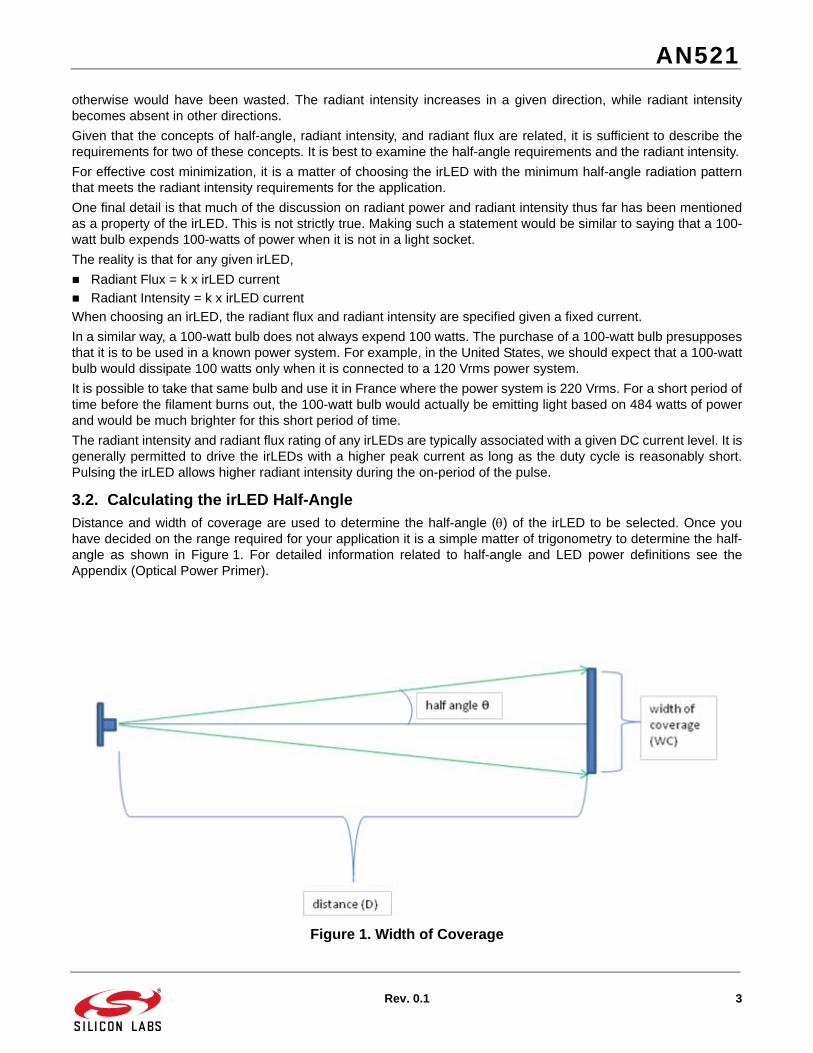
3.2. Calculating the irLED Half-AngleDistance and width of coverage are used to determine the half-angle () of the irLED to be selected. Once youhave decided on the range required for your application it is a simple matter of trigonometry to determine the half-angle as shown in Figure 1. For detailed information related to half-angle and LED power definitions see theAppendix (Optical Power Primer).
Figure 1. Width of Coverage

AN521
4 Rev. 0.1
Example: If the distance to the target is 100 cm and width of coverage 100 cm, then:
irLEDs come in standard half-angles of 5, 10, 15, 20, 30, 60, etc. Choose the nearest half-angle available; in thiscase an angle of 30 degrees would be appropriate to fully cover the target. An angle of 20 degrees could also workif the designer trades off a slightly longer distance to obtain the same width of coverage (e.g. D= (100 * 0.5) ÷tan(20) = 137cm).
3.3. Deciding Target Irradiance at the SensorIn prior sections it was stated that an irLED decision is contingent upon knowing the half-angle and the radiantintensity. The method of choosing the irLED radiant intensity is covered in the next section. However, before it ispossible to derive the radiant intensity of the irLED, it is important to know the minimum irradiance level needed atthe sensor. This section provides some guidelines for choosing the proper irradiance target.
Ee(sensor) is the power in mW/cm2 incident to the surface of the Si114x detector assuming that the irLED emitteris beside the Si114x, and that the target object is directly above both the irLED and the Si114x.
Fundamentally, the Si114x must be able to measure an increase in irradiance due to the irLED, compared to thebackground ambient level. The Si114x internally makes two measurements. The first measurement is made withthe irLED disabled to estimate the background IR radiation. The second measurement is with the irLED enabled.The Si114x reports the difference between these two measurements. The difference in reading is proportional tothe reflected light from the target object, illuminated by the irLED.
The required irradiance at the sensor is a function of the ambient IR noise level, the IR ambient level, the lightsource type, and the ADC setting used by the Si114x.
Assuming that the sensor is operating indoors, illuminated with artificial light sources with at maximum expectedlight levels of less than 450 lux incandescent or 1 klx of CFL lighting, the default Si114x Proximity ADC Setting canbe used. Under this condition, 4 uW/cm2 is the minimum irradiance target at the sensor.
For applications that need to operate under high levels of artificial lighting (but less than 6.5 klx incandescent or14.5 klx of CFL lighting), the HSIG bit in the PS_ADC_MISC needs to be set. The minimum irradiance at thesensor in this case is 58 uW/cm2.
For applications operating outdoors but not under direct sunlight, the PS_ADC_MISC HSIG bit should be set. Theminimum irradiance target of 7 uW/cm2 would be sufficient.
For use under direct sunlight, in addition to setting the HSIG bit, the PS_ADC_MUX may also need to beconfigured to use the smaller IR photodiode to avoid saturation. In this case, the minimum irradiance target is 45uW/cm2.
Table 1. Typical Ee Design Targets
Ee (sensor) Minimum
HSIG Bit IR Photo Diode
ADC Integration
Time
Usage (no overlay assumed)
0.25 uW/cm2 No Large 408.6 s Artificial Lighting CFL < 63 lx; Incandescent < 23 lx
0.5 uW/cm2 No Large 204.8 s Artificial Lighting CFL < 125 lx; Incandescent < 56 lx
1 uW/cm2 No Large 102.4 s Artificial Lighting CFL < 250 lx; Incandescent < 112 lx
2 uW/cm2 No Large 51.2 s Artificial Lighting CFL < 500 lx; Incandescent < 225 lx
4 uW/cm2 No Large 25.6 s Artificial Lighting CFL < 1 klx; Incandescent < 450 lx
8 uW/cm2 Yes Large 25.6 s Artificial Lighting CFL < 2 klx; Incandescent < 900 lx
arctan 100 0.5 100 26.6 degrees= =

AN521
Rev. 0.1 5
In general, for most hand-held applications, 8 uW/cm2 is a good minimum irradiance target to use for choosing anirLED. This allows operation under typical indoor lighting conditions and allows operation outdoors. For the rest ofthis document, 8 uW/cm2 is assumed in all calculations. Choosing a higher Ee value at the sensor would lead to anirLED with a higher radiant intensity, leading to trade-offs on radiation pattern or irLED cost.
16 uW/cm2 Yes Large 25.6 s Artificial Lighting CFL < 4 klx; Incandescent < 1.8 klx
32 uW/cm2 Yes Large 25.6 s Artificial Lighting CFL < 8 klx; Incandescent < 3.6 klx
58 uW/cm2 Yes Large 25.6 s Artificial Lighting CFL < 14.5 klx; Incandescent < 6.5 klx
7 uW/cm2 Yes Large 25.6 s Indirect Sunlight < 16 klx
22 uW/cm2 Yes Small 51.2 s Direct Sunlight < 80 klx
45 uW/cm2 Yes Small 25.6 s Direct Sunlight < 190klx
Table 1. Typical Ee Design Targets (Continued)
Ee (sensor) Minimum
HSIG Bit IR Photo Diode
ADC Integration
Time
Usage (no overlay assumed)
AN521
6 Rev. 0.1
3.4. Calculating Minimum Radiant IntensityThis section uses the definitions and equations for the power reflected and received by the sensor developed in theappendix "Optical Power Primer". Refreshing the definitions:
Ee(sensor) is the power in mW/cm2 incident to the surface of the Si114x detector having an emitter directly adjacent and having equal distances to the target object to be sensed.
Ie(0) is the peak radiant intensity of the source emitter in mW/sr. This parameter is the goal of this section, to be solved for, once all the objectives are defined.
is the reflectivity of the object to be sensed, as a fraction or percentage of incident light reflected.
A-area is the area of the object to be sensed in cm2.
D is the distance from emitter/detector to target object in cm.
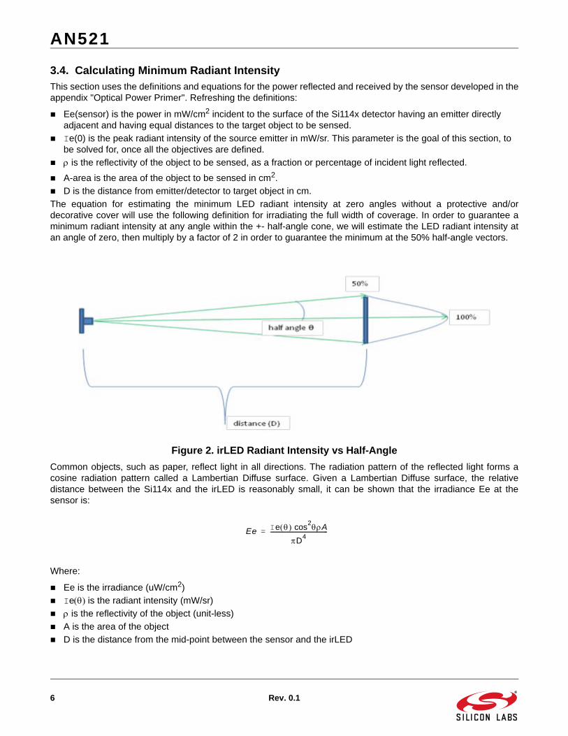
The equation for estimating the minimum LED radiant intensity at zero angles without a protective and/ordecorative cover will use the following definition for irradiating the full width of coverage. In order to guarantee aminimum radiant intensity at any angle within the +- half-angle cone, we will estimate the LED radiant intensity atan angle of zero, then multiply by a factor of 2 in order to guarantee the minimum at the 50% half-angle vectors.
Figure 2. irLED Radiant Intensity vs Half-Angle
Common objects, such as paper, reflect light in all directions. The radiation pattern of the reflected light forms acosine radiation pattern called a Lambertian Diffuse surface. Given a Lambertian Diffuse surface, the relativedistance between the Si114x and the irLED is reasonably small, it can be shown that the irradiance Ee at thesensor is:
Where:
Ee is the irradiance (uW/cm2)
Ie is the radiant intensity (mW/sr)
is the reflectivity of the object (unit-less)
A is the area of the object
D is the distance from the mid-point between the sensor and the irLED
Ee Ie cos2A
D4
-----------------------------------------=

AN521
Rev. 0.1 7
Rearranging the above equation, we have
When the irLED illuminating a target at its half-angle point, the radiant intensity is half the radiant intensity at itsaxial direction:
For half-angles of less than 15 degrees, a good approximation is
The Ee(sensor) needed in this equation is dependent on the expected ambient IR noise level at a given Si114xADC setting. The Si114x supports numerous ADC settings, photodiodes, and integration times. The ADC settingseach have different sensitivity and maximum light handling capability.
For any given Si114x ADC setting, there is a trade-off between sensitivity and maximum light handling capability.When operating with high sensitivity, the ADC saturates at lower ambient light levels. On the other hand, whenoperating at a high range setting, then the Si114x ADC can handle high levels of infrared levels, such as directsunlight, however, the sensitivity is lowered.
The minimum Ee(sensor) is a function of the expected IR noise ambient. Conceptually, the additional irradiancemeasured at the sensor needs to be larger than the IR noise ambient. If the system is expected to operate at highlevels of infrared ambient levels, then the necessary Ee(sensor) needs to also increase so that the reflectance canbe measured above the noise threshold.
The noise theory discussion is outside the scope of this application note. In this document, the recommendedminimum Ee(sensor) noise targets are covered in Section “3.3. Deciding Target Irradiance at the Sensor” .Depending on the application, the proper Ee(sensor) should be used. In this sub-section, the assumption is madethat 8 uW/cm2 is a sufficient goal for general indoor applications and operation outdoors, but not under directsunlight.
Going back to the equation, we are making an assumption that if the target object's reflected light can illuminate thesensor such that the irradiance at the sensor needs to be 8 uW/cm2, then this would essentially derive theminimum radiant intensity Ie(0) required of the irLED. The scope of this application note is to provide the practicaltheory necessary to make these decisions. The choice of Ee(sensor) is an important factor.
8 µW/cm2 is, at the very least, a good starting point.
Example: Ee(sensor) = 8 µW/cm2, D=20cm, =47% & target area= 120 cm2 (15 cm x 8 cm approximate size of ahuman hand)
Ie EeD4
cos2A
-----------------------=
Ie half – angle Ie 0 2
---------------=
Ie 0 2.15EeD4
A------------------------------=
Ie 0 2.15 x 8e 6 204
0.47 120 – 153 mW sr= =

AN521
8 Rev. 0.1
3.5. Overlay and Radiant IntensityThe result of the example in Section “3.4. Calculating Minimum Radiant Intensity” does not take into account thatthe irLED and Si114x is most likely under a product cover or overlay. These covers are typically used to hide theelectronics from plain view. There is expected to be light loss due to internal reflections.
The existence of the overlay has two effects; it narrows the width of coverage (as shown in Figure 4) and reducesthe transmission of light due to reflections off the glass surfaces.
Therefore, the minimum radiant intensity peak should be increased to account for this light loss. In general, theoverlay transmittance dominates.
This is a general rule of thumb:
Justifying this rule of thumb is best described with using the example in Section “3.4. Calculating Minimum RadiantIntensity” , but with an overlay on top of it. The rule of thumb generally will yield a result in an irLED choice with ahigher radiant intensity than is really necessary, leading to an irLED choice that would work for the application, butnot necessarily the lowest cost.
Calculating the minimum radiant intensity (Ie) required for the emitter mounted under a protective and/ordecorative cover has the following assumptions:
The cover is made of a visibly dark tinted glass and is 0.25 cm in thickness.
The cover attenuates both the emitted and received radiant intensity.
The attenuation factor (AF) for the cover at NIR wavelengths is 56% due to the tinting and does not appreciably change the index of refraction of glass.
Width of coverage = 20 cm, distance = 20 cm
Optical isolation between emitter and detectorNote: This example assumes perfect isolation, which is not always the case.
Figure 3. Overlay Refraction and Reflection
Ie 0 overlay1.2 Ie 0 no overlay
AF2
------------------------------------------------------------=
AN521
Rev. 0.1 9
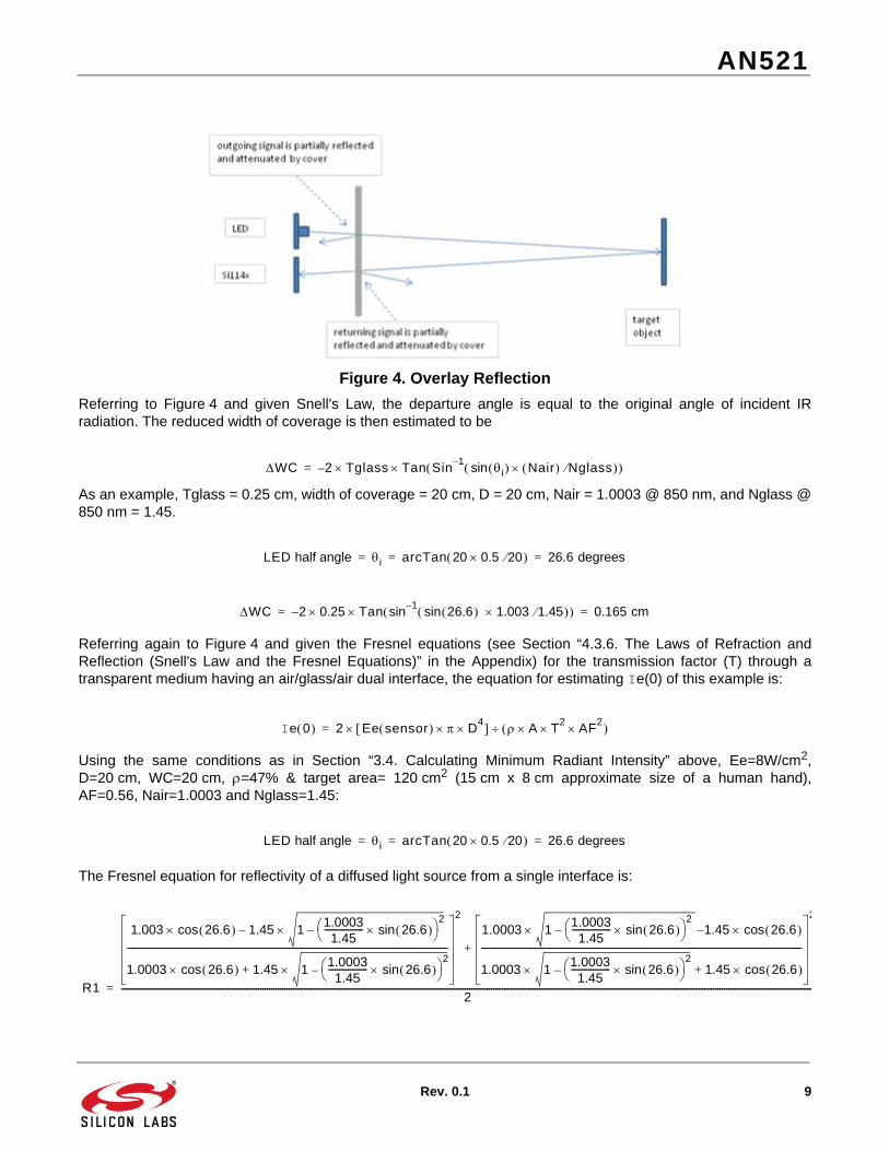
Figure 4. Overlay Reflection
Referring to Figure 4 and given Snell's Law, the departure angle is equal to the original angle of incident IRradiation. The reduced width of coverage is then estimated to be
As an example, Tglass = 0.25 cm, width of coverage = 20 cm, D = 20 cm, Nair = 1.0003 @ 850 nm, and Nglass @850 nm = 1.45.
Referring again to Figure 4 and given the Fresnel equations (see Section “4.3.6. The Laws of Refraction andReflection (Snell's Law and the Fresnel Equations)” in the Appendix) for the transmission factor (T) through atransparent medium having an air/glass/air dual interface, the equation for estimating Ie(0) of this example is:
Using the same conditions as in Section “3.4. Calculating Minimum Radiant Intensity” above, Ee=8W/cm2,D=20 cm, WC=20 cm, =47% & target area= 120 cm2 (15 cm x 8 cm approximate size of a human hand),AF=0.56, Nair=1.0003 and Nglass=1.45:
The Fresnel equation for reflectivity of a diffused light source from a single interface is:
WC 2– Tglass Tan Sin1– i sin Nair Nglass =
LED half angle i arcTan 20 0.5 20 26.6 degrees= = =
WC 2– 0.25 Tan sin1–
26.6 sin 1.003 1.45 0.165 cm= =
Ie 0 2 Ee sensor D4 A T
2AF
2 =
LED half angle i arcTan 20 0.5 20 26.6 degrees= = =
R1
1.003 26.6 cos 1.45 11.00031.45
------------------ 26.6 sin 2
––
1.0003 26.6 cos 1.45 11.00031.45
------------------ 26.6 sin 2
–+
---------------------------------------------------------------------------------------------------------------------------------------------------
2
1.0003 11.00031.45
------------------ 26.6 sin 2
– 1.45 26.6 cos–
1.0003 11.00031.45
------------------ 26.6 sin 2
– 1.45 26.6 cos+
---------------------------------------------------------------------------------------------------------------------------------------------------
2
+
2-------------------------------------------------------------------------------------------------------------------------------------------------------------------------------------------------------------------------------------------------------------------------------------------------------------------------------=

AN521
10 Rev. 0.1
The total reflected light from both the front and back side glass interfaces is Rtotal = 2 x R1 /(1 + R1) = 0.0657 or6.6% of the incident light is reflected away and lost at the point where the half-angle vector of light strikes the cover.Therefore the amount of light transmitted is equal to T = 1-R = 0.0934 or 93.4%. The value of e(0) required of theLED for this application is:
At an angle of zero the value of T is increased to 93.5%, therefore the attenuation of the incident light due to thereflection coefficient of glass is roughly constant out to the "critical angle". For glass this angle is approximately 43degrees at the exiting glass/air interface, at this "critical angle" total internal reflection occurs and the amount oflight lost due to reflections inside the glass cover can increase dramatically.
Going back to the rule of thumb…
Using this equation and starting with the Ie (no overlay) example from Section“3.4. Calculating Minimum RadiantIntensity” of 142 mW/cm2, we get:
560 mW/cm2 is slightly less than the 585 mW/cm2 derived from the rule of thumb. In general, the equation usingthe rule of thumb is easier to use, but will not necessarily lead to the least expensive choice. Also note that the ruleof thumb applies if the index of refraction used in the actual overlay does not significantly deviate from thisexample. In general, however, the index of refraction is a material property, with less variance compared to theoverlay transmittance, which is controlled through ink or impurities added to the base material for the purpose ofachieving a given look or color.
The overlay transmittance can be characterized and measured using the following items:
Radiometer
850 nm irLED source
The overlay transmittance is basically the ratio of a radiometer reading with and without an overlay. The actualradiant intensity used for the measurement is not important. The only thing important is that the irLED is sourcedwith enough current to make a reading, and that the radiometer is sensitive to 850 nm.
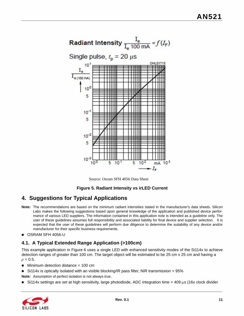
3.6. Radiant Intensity and irLED CurrentThe rated radiant intensity of an irLED is typically associated with a given irLED current. The Si114x provides thesystem designer the choice of using any of fifteen settings. The rated irLED radiant intensity is a function of theirLED current used. A manufacturer's data sheet typically shows this function.
In the example below, the rated radiant intensity is at 100 mA. To derive what the radiant intensity at 400 mA, thetable shows that the radiant intensity at 400 mA is approximately 3.5 times that at 100 mA.
Ie 0 2.15 8e 6– 204 0.47 120 0.934 2 0.56 2 560 mW sr==
Ie 0 overlay
1.2 Ie 0 no overlay
AF2
---------------------------------------------------=
585 mW cm2 1.2 153 0.562=
AN521
Rev. 0.1 11
Figure 5. Radiant Intensity vs irLED Current
4. Suggestions for Typical Applications
Note: The recommendations are based on the minimum radiant intensities stated in the manufacturer's data sheets. SiliconLabs makes the following suggestions based upon general knowledge of the application and published device perfor-mance of various LED suppliers. The information contained in this application note is intended as a guideline only. Theuser of these guidelines assumes full responsibility and associated liability for final device and supplier selection. It isexpected that the user of these guidelines will perform due diligence to determine the suitability of any device and/ormanufacturer for their specific business requirements.
OSRAM SFH 4056-U
4.1. A Typical Extended Range Application (>100cm)This example application in Figure 6 uses a single LED with enhanced sensitivity modes of the Si114x to achievedetection ranges of greater than 100 cm. The target object will be estimated to be 25 cm x 25 cm and having a = 0.5.
Minimum detection distance = 100 cm
Si114x is optically isolated with an visible blocking/IR pass filter, NIR transmission > 95% Note: Assumption of perfect isolation is not always true.
Si114x settings are set at high sensitivity, large photodiode, ADC integration time = 409 s (16x clock divider
Source: Osram SFH 4056 Data Sheet

AN521
12 Rev. 0.1
setting).
Object size >= 625 cm2, reflectivity => 50%
Width of coverage: 25 cm
Irradiance at Si114x Ee = 0.25 uW/cm2
Figure 6. 100 cm Example
The half-angle of the irLED needed for this application is:
An irLED with a wider half-angle than 7 degrees would be suitable for this application. Note however that if theirLED's half-angle is wider than the half-angle needed for the application, we will need to adjust the Ie(0) equationsince the prior equations have assumed illumination at the half-angle point.
For example, the SFH 4259S from OSRAM is a 15-degree device. The radiation pattern shows that at 7 degreesfrom the data sheet, the radiant intensity is shown to be 85% of the peak radiant intensity relative to the relativeintensity in the axial direction.
Starting from this equation
Evaluating the cosine at 7 degrees and given that
Therefore:
And
arc 12.5 100 tan 7 degrees= =
Ie EeD4
2Acos
--------------------------=
Ie 7 0.85 Ie 0 =
Ie 0 EeD4
0.84A-------------------=

AN521
Rev. 0.1 13
To make adjustments for the overlay transmittance,
Ie(0) = 295 * 1.2 / (0.95^2) = 392 mW/sr
At 400 mA, the radiant intensity of the SFH 4259S is 5 times the typical rated radiant intensity of 130 mW/sr whichwould lead to 650 mW/sr, easily meeting the 392 mW/sr requirement.
Silicon Labs makes the following suggestions based upon general knowledge of the application and publisheddevice performance of various LED suppliers. The information contained in this application note is intended as aguideline only. The user of these guidelines assumes full responsibility and associated liability for final device andsupplier selection. It is expected that the user of these guidelines will perform due diligence to determine thesuitability of any device and/or manufacturer for their specific business requirements.
OSRAM SFH 4259S, SFH 4550, SFH 4556
Vishay TSHG5410
Everlight HIR5393C/L223
4.2. A Typical One-Dimensional Linear Position Sensing Application (11 cm)In this application the objective is to detect a one-dimensional linear movement along the plane that intersects theradiation cones of the LEDs (see Figure 7). In this section, the application will be referred to as an irSLIDER.
Each LED is turned on at different times measuring the reflected power with each sample processed by the Si114xand host MCU. If the reflected power levels are equal, the position is directly above the Si114x detector. The actualmath involved in implementing an irSLIDER is beyond the scope of this document.
The most important concept is to recognize that the light from each irLED must reach the entire width of theirSLIDER and that the light reflected from the extreme angles should reach the Si114x.
The assumptions are given as:
1 cm separation between each LED to Si114x
Clear acrylic cover with NIR transmission >95%
Optical isolation between emitter and detector
Minimum width of coverage is 11 cm @ 6 cm distance
Object size is 6 x 10 cm or about the average size of a human hand, = 0.47
SMT low profile package
Ie 0 0.25e 6– 1004 0.84 0.5 625 295 mW sr==

AN521
14 Rev. 0.1
Figure 7. 11 cm irSLIDER
In an irSLIDER application, width of coverage is pretty wide. Operation outside the half-angle is necessary. It isbest to choose a wide half-angle irLED and then determine the necessary Ie(0) after examining the I() based onthe worst case radiation angle.
Starting from this equation:
From the SFH 4056 data sheet, it can be shown that at 51 degrees:
Considering the cosine at 51 degrees and substituting the above equation:
The proper distance to use for this is the mid-point between the irLED and the sensor. Since it is close enough, anduses the irLED distance, there would be some margin built-in. The distance from the irLED to the target is derivedfrom the Pythagorean theorem and has been calculated and shown in Figure 7. For Ee, 8 uW/cm2 is a good targetirradiance to have for indoor use and outdoor use.
Adjusting for the overlay
Ie(0) = 189 x 1.2 / (.95)^2 = 251 mW/sr
Ie EeD4
2Acos
--------------------------=
Ie 51 0.11 Ie 0 =
Ie 0 EeD4
0.04A-------------------=
Ie 0 8e 6 9.64– 0.04 0.47 60 189 mW sr= =

AN521
Rev. 0.1 15
Based on the data sheet, the SFH 4056 devices driven at 400 mA has a radiant intensity 4 times the radiantintensity than when driven at 70 mA.
The SFH 4056-U has a typical radiant intensity of Ie(0) between 40 mW/sr to 80 mW/sr. This translates to an Ie(0)of between 160 mW/sr to 320 mW/sr. The requirement of 251 mW/sr is between the min/max levels.
It is recommended that a shorter slider be considered when operation under direct sunlight is a productrequirement. Alternatively, the product cover should be chosen so that the cover has high transmittance at 850 nm,while reducing as much background IR as possible.
4.3. A Typical Cell Phone and/or Hand-held Appliance (<5 cm)The example application of Figure 8 uses a single LED with medium sensitivity modes of the Si114x to achievedetection ranges < 5cm. The target object will be assumed to be roughly the size of the cheek of a face (25 cm2)and having a = 0.13. The low reflectivity of 0.13 is used instead of 0.47 to allow detection despite black hair. Theassumptions are:
Detection distance = < 5 cm
Si114x settings are set at highest range (small photodiode, HSIG enabled, A/D clk=1x)
Ee = 45 µW/cm2
Object size = 25 cm2, reflectivity (black hair) = 13%
Low profile SMT package
Figure 8. 5 cm Example
The nearest half-angle available that is greater is 30 degrees. Any half-angle greater than 24 degrees and havingthe minimum power calculated is a candidate for this application. The radiant intensity equation for this applicationis:
arc 2.25 5 tan 24 degrees= =
Ie EeD4
2Acos
--------------------------=

AN521
16 Rev. 0.1
At the half-angle point, Ie() = 2 Ie(0). Since the half-angle is 30 degrees,
Taking into account the cover:
Ie(0) = 65 x 1.2 / 0.8^2 = 121 mW/sr
An Osram SFH 4056 at 400 mA has 4 times the radiant intensity at 70 mA. The SFH 4056 has a typical radiantintensity of 35 mW/sr at 70 mA. Therefore, the expected radiant intensity is 140 mW/sr at 400 mA. This allows theSi114x to detect black hair even under direct sunlight.
If detecting black hair is not a design goal, then the reflectivity increases by a factor of 3.6, and the resulting radiantintensity requirement decreases by a factor of 3.6. In that case, more options are available for cheek detection, butmay not be able to detect black hair.
Osram SFH 4056
Ie 0 2 45e 6 54
24 2 0.13 25cos – 65 mW sr= =

AN521
Rev. 0.1 17
APPENDIX—OPTICAL POWER PRIMER
irLEDs used for Si114x proximity sensing applications have radiation emissions in the near infrared region (NIR) ofthe electromagnetic spectrum, so called due to its close proximity to the visible light spectrum (as shown inFigure 10). The radiant flux of an irLED is defined as the total power radiated over the full range of emission(shown in Figure 9).
Figure 9. Typical 850 nm irLED Spectrum
Source: Osram SFH 4056 Data Sheet

AN521
18 Rev. 0.1
Figure 10. Electromagnetic Spectrum
irLEDs emit a non-coherent diffuse light pattern in the shape of a cone (as shown in Figure 11). The set ofcharacteristic specifications which describe this cone of radiation are half-angle () and radiant intensity (Ie)expresssed in milli-watts/steradian.
Source: Wikipedia

AN521
Rev. 0.1 19
Figure 11. Radiation Pattern of an irLED
4.3.1. Steradian
The steradian (symbol: sr) is the SI unit of solid angle. It is used to describe two-dimensional angular spans inthree-dimensional space, analogous to the way in which the radian describes angles in a plane (as shown inFigure 12).
The steradian, like the radian, is dimensionless because 1 sr = m2 x m-2 = 1. It is useful, however, to distinguishbetween dimensionless quantities of different nature, so in practice the symbol "sr" is used where appropriate,rather than the derived unit "1" or no unit at all. For example, radiant intensity can be measured in watts persteradian (W x sr–1).
Figure 12. Steradian Illustration
A steradian is defined as the solid angle subtended at the center of a sphere of radius r by a portion of the surfaceof the sphere whose area, A, equals r2.
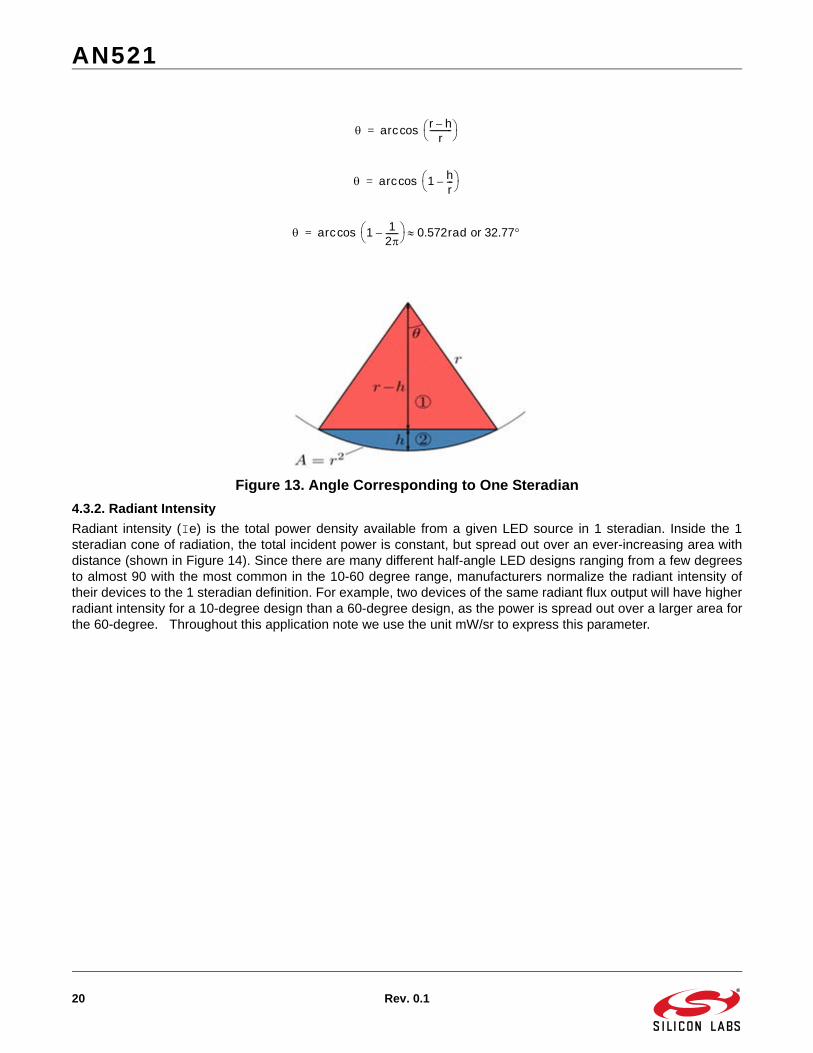
Since A = r2, it corresponds to the area of a spherical cap (A = 2rh) (wherein h stands for the "height" of the cap),and the relationship h/r = 1/(2) holds (as shown in Figure 13). Therefore one steradian corresponds to the solidangle of a simple cone subtending an angle with given by:
AN521
20 Rev. 0.1
Figure 13. Angle Corresponding to One Steradian
4.3.2. Radiant Intensity
Radiant intensity (Ie) is the total power density available from a given LED source in 1 steradian. Inside the 1steradian cone of radiation, the total incident power is constant, but spread out over an ever-increasing area withdistance (shown in Figure 14). Since there are many different half-angle LED designs ranging from a few degreesto almost 90 with the most common in the 10-60 degree range, manufacturers normalize the radiant intensity oftheir devices to the 1 steradian definition. For example, two devices of the same radiant flux output will have higherradiant intensity for a 10-degree design than a 60-degree design, as the power is spread out over a larger area forthe 60-degree. Throughout this application note we use the unit mW/sr to express this parameter.
arc r h–
r----------- cos=
arc 1 hr---–
cos=
arc 1 12------–
cos 0.572rad or 32.77=

AN521
Rev. 0.1 21
Figure 14. irLED Radiant Intensity
4.3.3. Irradiance
Irradiance is the power per unit area incident upon a surface at a specified distance. Since the total power incidentupon the surface is constant and the area increases with distance, the irradiance is then inversely proportional tothe distance from emitter to surface.
Given a point light source, the irradiance and radiant intensity are related by an inverse square law function:
Figure 15. Inverse Square Law for Point Source
As can be seen, the power falls off as the square of the distance with D=4 having 1/16 the power/area as D=1 (asshown in Figure 15).
Total power collected by surface is constantindependent of distance
E I D2=

AN521
22 Rev. 0.1
Example: A manufacturer’s data sheet may specify that an LED has 100 mW/sr, therefore at 1 m (100 cm) the (Ee)power/area is 100 mW/(100)2 or 10 µW/cm2, and at 4 m (400 cm) it is 0.625 µW/cm2.
In a proximity detector usage, irradiance measured at the sensor does not have an inverse square law relationshiprelative to the irLED illuminating the object. The irLED illuminates the object, and then the object reflects some ofthis light to the sensor. The irradiance measurement at the sensor is a function of the object’s reflectivity, area,distance, and its surface type.
Most objects fall into the category of a “diffuse” surface. In a proximity detector, the relationship between the irLEDsource and the irradiance measured at the sensor is actually an inverse fourth-law relationship.
It can be shown that if:
An irLED has a radiant intensity function Ie().
Object surface is a Lambertian diffuse surface with a reflectivity () and an area A.
The square root of A is less than 5 x D.
The sensor and irLED are located close to each other.
Then the irradiance measured at the sensor is:
Where:
Ee is the irradiance (uW/cm2).
Ie() is the radiant intensity (mW/sr).
() is the reflectivity of the object.
A is the area of the object.
D is the distance from the mid-point between the sensor and the irLED.
4.3.4. Half-Angle
irLEDs emit light in a teardrop configuration similar to Figure 16. This plot is important to understand because itrelates the radiant intensity as a function of the viewing angle measured from the 0° axis. Note that the power fallsoff as a function of this off-axis angle. The half-angle () is defined as that angle at which the power falls to 50% ofits 0° axis value. The zero axis power is the radiant intensity specified by the manufacturer in mW/sr.
Figure 16. Relative Radiant Intensity vs Off-Axis Angle
Ee Ie cos2A
D4
-----------------------------------------=

AN521
Rev. 0.1 23
In the example case above, the LED has a half-angle of ±+-17 degrees. A graphical vector representation ofradiant intensity can be seen in the following plot.
Figure 17. Example irLED, 17-Degree Half-Angle
4.3.5. Reflectivity
Reflectivity() is defined as the ratio of the total amount of radiation, as in light, reflected by a surface to the totalamount of radiation incident on the surface. Referring to Figure 18 as a flat diffuse surface that intersects the zeroaxis of the LED radiation pattern at a perpendicular, a portion of the incident light will be reflected back towards thesource as a function of material type and size (area).
Figure 18. Proximity System Illustration
4.3.6. The Laws of Refraction and Reflection (Snell's Law and the Fresnel Equations)
Snell’s Law is a formula used to describe the relationship between the angles of incidence and refraction whenreferring to light passing through a boundary between two different isotropic media, such as air and glass. The lawsays that the ratio of the sines of the angles of incidence and of refraction is a constant that depends on the media.
1sin
2sin--------------
v1
v2-----
n2
n1------= =
AN521
24 Rev. 0.1
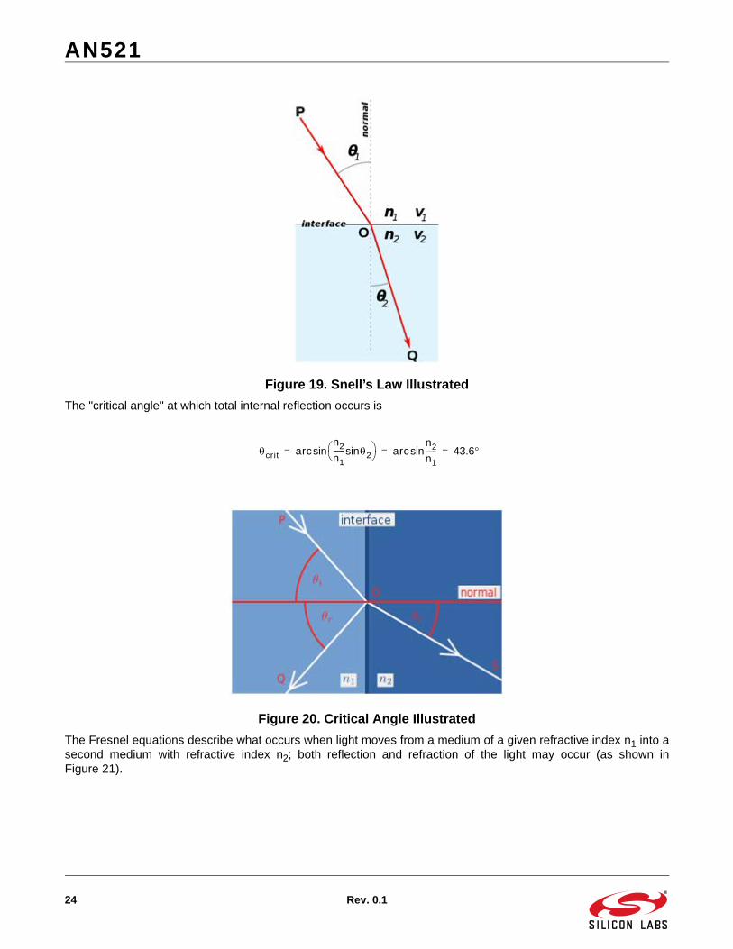
Figure 19. Snell’s Law Illustrated
The "critical angle" at which total internal reflection occurs is
Figure 20. Critical Angle Illustrated
The Fresnel equations describe what occurs when light moves from a medium of a given refractive index n1 into asecond medium with refractive index n2; both reflection and refraction of the light may occur (as shown inFigure 21).
crit arcn2
n1------ 2sin sin arc
n2
n1------sin 43.6= = =
AN521
Rev. 0.1 25
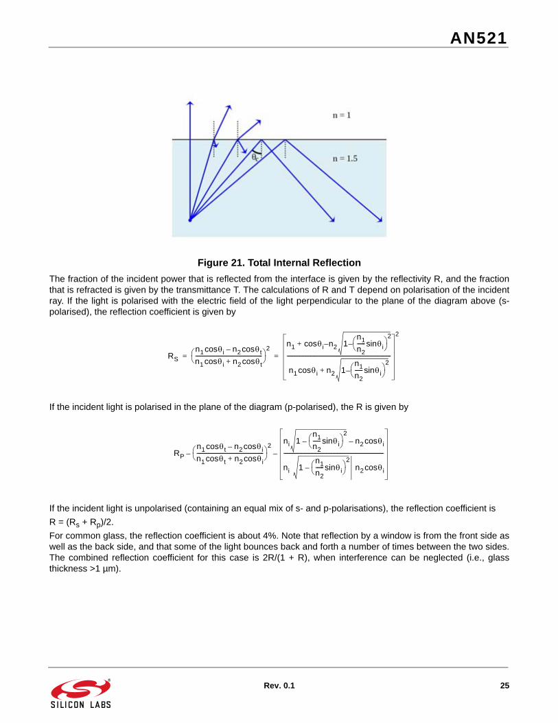
Figure 21. Total Internal Reflection
The fraction of the incident power that is reflected from the interface is given by the reflectivity R, and the fractionthat is refracted is given by the transmittance T. The calculations of R and T depend on polarisation of the incidentray. If the light is polarised with the electric field of the light perpendicular to the plane of the diagram above (s-polarised), the reflection coefficient is given by
If the incident light is polarised in the plane of the diagram (p-polarised), the R is given by
If the incident light is unpolarised (containing an equal mix of s- and p-polarisations), the reflection coefficient is
R = (Rs + Rp)/2.
For common glass, the reflection coefficient is about 4%. Note that reflection by a window is from the front side aswell as the back side, and that some of the light bounces back and forth a number of times between the two sides.The combined reflection coefficient for this case is 2R/(1 + R), when interference can be neglected (i.e., glassthickness >1 µm).
RS
n1 icos n2 tcos–
n1 icos n2 tcos+-------------------------------------------------
2n1 i n2 1
n1
n2------ isin –
2–cos+
n1 icos n2 1n1
n2------ isin –
2+
----------------------------------------------------------------------------
2
= =
RP
n1 tcos n2 icos–
n1 tcos n2 icos+-------------------------------------------------
2–
ni 1n1
n2------ isin
2– n2 icos–
ni 1n1
n2------ isin
2– n2 icos
-------------------------------------------------------------------------–

http://www.silabs.com
Silicon Laboratories Inc.400 West Cesar ChavezAustin, TX 78701USA
Smart. Connected. Energy-Friendly.
Productswww.silabs.com/products
Qualitywww.silabs.com/quality
Support and Communitycommunity.silabs.com
DisclaimerSilicon Laboratories intends to provide customers with the latest, accurate, and in-depth documentation of all peripherals and modules available for system and software implementers using or intending to use the Silicon Laboratories products. Characterization data, available modules and peripherals, memory sizes and memory addresses refer to each specific device, and "Typical" parameters provided can and do vary in different applications. Application examples described herein are for illustrative purposes only. Silicon Laboratories reserves the right to make changes without further notice and limitation to product information, specifications, and descriptions herein, and does not give warranties as to the accuracy or completeness of the included information. Silicon Laboratories shall have no liability for the consequences of use of the information supplied herein. This document does not imply or express copyright licenses granted hereunder to design or fabricate any integrated circuits. The products are not designed or authorized to be used within any Life Support System without the specific written consent of Silicon Laboratories. A "Life Support System" is any product or system intended to support or sustain life and/or health, which, if it fails, can be reasonably expected to result in significant personal injury or death. Silicon Laboratories products are not designed or authorized for military applications. Silicon Laboratories products shall under no circumstances be used in weapons of mass destruction including (but not limited to) nuclear, biological or chemical weapons, or missiles capable of delivering such weapons.
Trademark InformationSilicon Laboratories Inc.® , Silicon Laboratories®, Silicon Labs®, SiLabs® and the Silicon Labs logo®, Bluegiga®, Bluegiga Logo®, Clockbuilder®, CMEMS®, DSPLL®, EFM®, EFM32®, EFR, Ember®, Energy Micro, Energy Micro logo and combinations thereof, "the world’s most energy friendly microcontrollers", Ember®, EZLink®, EZRadio®, EZRadioPRO®, Gecko®, ISOmodem®, Precision32®, ProSLIC®, Simplicity Studio®, SiPHY®, Telegesis, the Telegesis Logo®, USBXpress® and others are trademarks or registered trademarks of Silicon Laborato-ries Inc. ARM, CORTEX, Cortex-M3 and THUMB are trademarks or registered trademarks of ARM Holdings. Keil is a registered trademark of ARM Limited. All other products or brand names mentioned herein are trademarks of their respective holders.

![OPOTEK.COM • 760.929e n e rg y [m j] wavelength [nm] radiant x30 series opo output radiant nx9130 radiant qx8130 radiant nx6130 radiant qx4130 0 4 8 12 16 20 200 220 240 260 280](https://static.fdocuments.us/doc/165x107/60dc720ce9b2c615fe7d6fd3/a-760929-e-n-e-rg-y-m-j-wavelength-nm-radiant-x30-series-opo-output-radiant.jpg)