IRD-150 ICD-150 IRD-300 Steel Deck - Ideal Roofing · ROOF DECK, FLOOR DECK AND ACOUSTIC DECK...
34
www.idealroofing.com Steel Deck Technical Catalog IRD-150 IRD-300 ICD-300 ICD-150
Transcript of IRD-150 ICD-150 IRD-300 Steel Deck - Ideal Roofing · ROOF DECK, FLOOR DECK AND ACOUSTIC DECK...

www.idealroofing.com
Steel Deck Technical Catalog
IRD-150
IRD-300
ICD-300
ICD-150

Check out Ideal Roofing’s wide range of roofing and siding panels on the last two pages of this
catalog or visit www.idealroofing.com.To talk to a sales representative: 1 800 267-0860
Residential IndustrialCommercial
ROOF DECK, FLOOR DECK AND ACOUSTIC DECK PANELSIdeal Roofing manufactures a complete range of coated steel roof, floor and acoustic deck panels using state-of-the-art roll-forming machinery. These panels are cut to length to your specifications and delivered to the job sites using Ideal’s own fleet of trucks.
Steel Deck

Table of Contents Page
Deck Selection������������������. 2 Roof Deck
- IRD-150 / IRD-151 (Imperial)�������� 3-4 - IRD-150 / IRD-151 (Metric)��������... 5-6 - IRD-300 / IRD-301 (Imperial)�������� 7-8 - IRD-300 / IRD-301 (Metric)��������... 9-10 Composite Floor Deck
- ICD-150 / ICD-151 (Imperial)�������� 11-12 - ICD-150 / ICD-151 (Metric)��������... 13-14 - ICD-150 / ICD-151, INVERTED (Imperial)��.. 15-16 - ICD-150 / ICD-151, INVERTED (Metric)���. 17-18
- ICD-300 / ICD-301 (Imperial)�������� 19-20 - ICD-300 / ICD-301 (Metric)��������... 21-22 - ICD-300 / ICD-301, INVERTED (Imperial)��.. 23-24 - ICD-300 / ICD-301, INVERTED (Metric)���. 25-26 Acoustic Deck & Deck Accessories - IRD-150 / IRD-151������������.. 27 - IRD-300 / IRD-301������������.. 28 Profile Selection������������������29-30 Certificates of Compliance: “FM Approved”������. 31 Certificate of Compliance: “Underwriters Laboratories”�. 32


Midspan Support
0.190 0.195 174 43.5 305 51.9
0.231 0.242 258 64.5 456 77.6
0.314 0.319 477 119 853 145
0.394 0.394 765 191 1377 234
0.030 0.036 0.048 0.060 0.030 0.036 0.048 0.060 0.030 0.036 0.048 0.060
S 278 339 460 578 285 355 468 578 356 444 585 723
D 467 578 783 975 1110 1376 1863 2319 882 1093 1480 1842
S 204 249 338 425 210 261 344 425 262 326 430 531
D 294 364 493 614 699 867 1173 1461 555 688 932 1160
S 157 191 259 325 160 200 263 325 201 249 329 407
D 197 244 330 411 468 581 786 978 372 461 624 777
S 124 151 204 257 127 158 208 257 158 197 260 321
D 138 171 232 289 329 408 552 687 261 324 438 546
S 100 122 166 208 103 128 168 208 128 160 211 260
D 101 125 169 211 240 297 402 501 190 236 320 398
S 83 101 137 172 85 106 139 172 106 132 174 215
D 76 94 127 158 180 223 302 376 143 177 240 299
S 70 85 115 145 71 89 117 145 89 111 146 181
D 58 72 98 122 139 172 233 290 110 137 185 230
S 59 72 98 123 61 76 100 123 76 94 125 154
D 46 57 77 96 109 135 183 228 87 107 145 181
S 51 62 84 106 52 65 86 106 65 81 107 133
D 37 46 62 77 87 108 147 183 69 86 116 145
S 45 54 74 93 46 57 75 93 57 71 94 116
D 30 37 50 62 71 88 119 148 56 70 95 118
S 39 48 65 81 40 50 66 81 50 62 82 102
D 25 30 41 51 59 73 98 122 47 58 78 97
S 35 42 57 72 36 44 58 72 44 55 73 90
D 21 25 34 43 49 61 82 102 39 48 65 81
S 31 38 51 64 32 39 52 64 40 49 65 80
D 17 21 29 36 41 51 69 86 33 40 55 68
S 28 34 46 58 28 35 47 58 36 44 58 72
D 15 18 25 31 35 43 59 73 28 34 47 58
S 25 31 41 52 26 32 42 52 32 40 53 65
D 13 16 21 26 30 37 50 63 24 30 40 50
S 23 28 38 47 23 29 38 47 29 36 48 59
D 11 13 18 23 26 32 43 54 21 25 35 43
S 21 25 34 43 21 26 35 43 27 33 43 54
D 9 12 16 20 23 28 38 47 18 22 30 37
Notes: 1 Based on ASTM A 653 Grade 33 structural steel.
2 Values in row "S" are based on strength.
3 Values in row "D" are based on deflection of 1/240th span.
4 Web crippling not included in strength calculations. See example.
Limit States Design principles were used in accordance with CSA Standard S136-12
SECTION PROPERTIES (Per foot of width)
IMPERIAL
Base Steel
Thickness
(in.)
Coated Steel
Thickness
(G90)
(in.)
Coated
Weight
(psf)
Sec. ModulusDeflection
Moment of
Inertia
(in.4)
Specified Web Crippling Data
Pe1 End
(lb)
Pe2 End
(lb)
Pi1 Interior
(lb)
Pi2 Interior
(lb)(in.
3) (in.
3)
0.030 0.0315 1.61 0.174
0.036 0.0375 1.93 0.218
0.048 0.0495 2.56 0.291
0.060 0.0615 3.20 0.362
MAXIMUM UNIFORMLY DISTRIBUTED SPECIFIED LOADS (PSF) LLF = 1.50; IMPF = 0.90; NORMAL OCCUPANCY = 1.0
SPAN
LENGTH
(ft)
1-SPAN 2-SPAN 3-SPAN
BASE STEEL THICKNESS (inches) BASE STEEL THICKNESS (inches) BASE STEEL THICKNESS (inches)
3.0
3.5
4.0
4.5
5.0
5.5
6.0
6.5
7.0
7.5
8.0
8.5
11.0
9.0
10.5
9.5
10.0

GENERAL INFORMATION
General
Presented in these load tables are maximum uniformly
distributed specified loads.
� Limit States Design (LSD)
Strength - Limit States Design principles were used in
the development of the load tables in accordance with
CSA-S136-01, North American Specification for the
Design of Cold Formed Steel Structural Members and
the National Building Code of Canada,. The factored
resistance under consideration, φR, must be equal to or
greater than the effect of the factored loads, i.e.,
φφφφ R ≥≥≥≥ Effect of Factored Loads.
Hence, a short calculation must be carried out to
compute the specified live load. See example.
Serviceability – Maximum specified deflection loads
given in the tables must be compared with their
respective specified live loads.
� Steel
Specification - Conforms to ASTM A653M grade
230; Yield strength 230 MPa (33 ksi) and tensile
strength of 310 MPa (45 ksi).
Finishes – ZF 075 (A25) or Z275 (G90). For heavier
galvanizing, refer to ASTM A653-A653M.
� Design Considerations
Strength - The maximum uniformly distributed
specified load obtained from the load table must be
equal to or greater than (Specified live load + 0.833
times the specified dead load).
Where 0.833 = 1.25/1.5.
Conservative Strength Approach - The maximum
uniformly distributed specified load obtained from the
load table must be equal to or greater than (Specified
live load + specified dead load).
Web Crippling Check – If n/t > 210, use n/t = 210.
Serviceability (Deflection) – The effective moment of
inertia for deflection determination has been calculated
at an assumed specified live load stress of 0.6Fy.
EXAMPLE
1 1/2” DECK (IMPERIAL)
Given:
� Triple span continuous, L = 8 ft each span
� Deck thickness, t = 0.030 in
� L/180 deflection limit (data in tables are based on
L/240)
� Bearing length, n = 2 in.
� Specified loads
1) Dead loads (DL)
a) deck 1.6 psf
b) superimposed 8.2 psf
DL = 9.8 psf
2) Live load (LL)
LL = 40 psf
Solution:
� Strength
1) Specified loads
[LL + 0.833 DL]
[40 + 0.833 (9.8)] = 48.2 psf
2) Maximum specified load (from Table under “S”)
is 50 psf
Since 50 > 48.2 ∴∴∴∴ ΟΚ
3) Check end web crippling (n = 2 in.)
a) Specified end reaction
0.400(48.2)8.0 = 154 lb/ft
b) Maximum specified end reaction
(from Section Property Table)
Pe = Pe1 + Pe2 t/n
Pe = 174 + 43.5 030.0/2 = 529 lb/ft
Since 529 > 154 ∴∴∴∴ ΟΚ
4) Check interior web crippling (n = 2 in.)
a) Specified interior reaction
1.10(48.2)8.0 = 424 lb/ft
b) Maximum specified interior reaction
(from Section Property Table)
Pi = Pi1 + Pi2 t/n
Pi = 305 + 51.9 030.0/2 = 729 lb/ft
Since 729 > 424 ∴∴∴∴ ΟΚ
� Deflection
From Table under “D” (L/240) = 47 psf
For L/180, multiply 47 by 240/180 = 63 psf.
Since 63 is > 40 ∴∴∴∴ ΟΚ

Midspan Support
10.2 10.4 2.57 0.642 4.50 0.766
12.4 13.0 3.81 0.952 6.73 1.14
16.9 17.2 7.04 1.76 12.6 2.14
21.2 21.2 11.3 2.82 20.3 3.45
0.762 0.914 1.219 1.524 0.762 0.914 1.219 1.524 0.762 0.914 1.219 1.524
S 11.3 13.7 18.6 23.4 11.5 14.4 18.9 23.4 14.4 18.0 23.7 29.3
D 17.1 21.2 28.7 35.7 40.6 50.4 68.2 84.9 32.2 40.0 54.2 67.4
S 7.82 9.52 12.9 16.3 8.00 9.97 13.2 16.3 10.0 12.5 16.4 20.3
D 9.87 12.2 16.6 20.7 23.5 29.1 39.5 49.1 18.7 23.1 31.4 39.0
S 5.74 6.99 9.49 11.9 5.88 7.33 9.66 11.9 7.35 9.16 12.1 14.9
D 6.22 7.71 10.5 13.0 14.8 18.4 24.9 30.9 11.8 14.6 19.7 24.6
S 4.40 5.35 7.27 9.14 4.50 5.61 7.40 9.14 5.63 7.01 9.24 11.4
D 4.16 5.16 7.00 8.71 9.91 12.3 16.7 20.7 7.87 9.76 13.2 16.5
S 3.47 4.23 5.74 7.22 3.56 4.43 5.84 7.22 4.45 5.54 7.30 9.03
D 2.93 3.63 4.91 6.12 6.96 8.63 11.7 14.6 5.53 6.86 9.29 11.6
S 2.81 3.43 4.65 5.85 2.88 3.59 4.73 5.85 3.60 4.49 5.92 7.31
D 2.13 2.64 3.58 4.46 5.08 6.29 8.53 10.6 4.03 5.00 6.77 8.43
S 2.33 2.83 3.84 4.83 2.38 2.97 3.91 4.83 2.98 3.71 4.89 6.04
D 1.60 1.99 2.69 3.35 3.81 4.73 6.41 7.97 3.03 3.75 5.09 6.33
S 1.95 2.38 3.23 4.06 2.00 2.49 3.29 4.06 2.50 3.12 4.11 5.08
D 1.23 1.53 2.07 2.58 2.94 3.64 4.93 6.14 2.33 2.89 3.92 4.88
S 1.66 2.03 2.75 3.46 1.70 2.12 2.80 3.46 2.13 2.66 3.50 4.33
D 0.97 1.20 1.63 2.03 2.31 2.86 3.88 4.83 1.83 2.27 3.08 3.84
S 1.44 1.75 2.37 2.98 1.47 1.83 2.41 2.98 1.84 2.29 3.02 3.73
D 0.78 0.96 1.31 1.63 1.85 2.29 3.11 3.87 1.47 1.82 2.47 3.07
S 1.25 1.52 2.07 2.60 1.28 1.60 2.10 2.60 1.60 1.99 2.63 3.25
D 0.63 0.78 1.06 1.32 1.50 1.86 2.53 3.14 1.19 1.48 2.01 2.50
S 1.10 1.34 1.82 2.29 1.13 1.40 1.85 2.29 1.41 1.75 2.31 2.86
D 0.52 0.65 0.87 1.09 1.24 1.54 2.08 2.59 0.98 1.22 1.65 2.06
S 0.97 1.19 1.61 2.02 1.00 1.24 1.64 2.02 1.25 1.55 2.05 2.53
D 0.43 0.54 0.73 0.91 1.03 1.28 1.74 2.16 0.82 1.02 1.38 1.72
S 0.87 1.06 1.44 1.81 0.89 1.11 1.46 1.81 1.11 1.38 1.83 2.26
D 0.37 0.45 0.61 0.76 0.87 1.08 1.46 1.82 0.69 0.86 1.16 1.45
S 0.78 0.95 1.29 1.62 0.80 0.99 1.31 1.62 1.00 1.24 1.64 2.03
D 0.31 0.39 0.52 0.65 0.74 0.92 1.24 1.55 0.59 0.73 0.99 1.23
S 0.70 0.86 1.16 1.46 0.72 0.90 1.18 1.46 0.90 1.12 1.48 1.83
D 0.27 0.33 0.45 0.56 0.63 0.79 1.07 1.33 0.50 0.62 0.85 1.05
Notes: 1 Based on ASTM A 653 Grade 230 structural steel.
2 Values in row "S" are based on strength.
3 Values in row "D" are based on deflection of 1/240th span.
4 Web crippling not included in strength calculations. See example.
Limit States Design principles were used in accordance with CSA Standard S136-12
3.6
3.8
4.0
1.8
2.0
2.2
2.4
3.4
2.6
2.8
3.0
3.2
BASE STEEL THICKNESS (mm) BASE STEEL THICKNESS (mm)
1.0
1.2
1.4
1.6
1.524 1.564 15.6 0.494
MAXIMUM UNIFORMLY DISTRIBUTED SPECIFIED LOADS (kPA) LLF = 1.50; IMPF = 0.90; NORMAL OCCUPANCY = 1.0
SPAN
LENGTH
(m)
1-SPAN 2-SPAN 3-SPAN
BASE STEEL THICKNESS (mm)
0.914 0.954 9.42 0.298
1.219 1.259 12.5 0.397
Pi1
Interior
(kN)
Pi2
Interior
(kN)(10
3mm
3) (10
3mm
3)
0.762 0.802 7.86 0.237
SECTION PROPERTIES (Per meter of width)
METRIC
Base Steel
Thickness
(mm)
Coated Steel
Thickness
(Z275)
(mm)
Coated
Mass
(kg/m2)
Sec. ModulusDeflection
Moment of
Inertia
(106mm
4)
Specified Web Crippling Data
Pe1
End
(kN)
Pe2
End
(kN)

GENERAL INFORMATION
General
Presented in these load tables are maximum uniformly
distributed specified loads.
� Limit States Design (LSD)
Strength - Limit States Design principles were used in
the development of the load tables in accordance with
CSA-S136-01, North American Specification for the
Design of Cold Formed Steel Structural Members and
the National Building Code of Canada,. The factored
resistance under consideration, φR, must be equal to or
greater than the effect of the factored loads, i.e.,
φφφφ R ≥≥≥≥ Effect of Factored Loads.
Hence, a short calculation must be carried out to
compute the specified live load. See example.
Serviceability – Maximum specified deflection loads
given in the tables must be compared with their
respective specified live loads.
� Steel
Specification - Conforms to ASTM A653M grade
230; Yield strength 230 MPa (33 ksi) and tensile
strength of 310 MPa (45 ksi).
Finishes – ZF 075 (A25) or Z275 (G90). For heavier
galvanizing, refer to ASTM A653-A653M.
� Design Considerations
Strength - The maximum uniformly distributed
specified load obtained from the load table must be
equal to or greater than (Specified live load + 0.833
times the specified dead load).
Where 0.833 = 1.25/1.5.
Conservative Strength Approach - The maximum
uniformly distributed specified load obtained from the
load table must be equal to or greater than (Specified
live load + specified dead load).
Web Crippling Check – If n/t > 210, use n/t = 210.
Serviceability (Deflection) – The effective moment of
inertia for deflection determination has been calculated
at an assumed specified live load stress of 0.6Fy.
EXAMPLE
38 mm (1 1/2”) DECK (METRIC)
Given:
� Triple span continuous, L = 2.4 m each span
� Deck thickness, t = 0.762 mm
� L/180 deflection limit (data in tables are based on
L/240)
� Bearing length, n = 50 mm
� Specified loads
1) Dead loads (DL)
a) deck 0.1 kPa
b) superimposed 0.4 kPa
DL = 0.5 kPa
2) Live load (LL)
LL = 2.0 kPa
Solution:
� Strength
1) Specified loads
[LL + 0.833 DL]
[2.0 + 0.833 (0.5)] = 2.42 kPa
2) Maximum specified load (from Table under “S”)
is 2.50 kPa
Since 2.50 > 2.42 ∴∴∴∴ ΟΚ
3) Check end web crippling (n = 50 mm)
a) Specified end reaction
0.400(2.42)2.4 = 2.32 kN/m
b) Maximum specified end reaction
(from Section Property Table)
Pe = Pe1 + Pe2 tn /
Pe = 2.57 + 0.642 762.0/50 = 7.77 kN/m
Since 7.77 > 2.32 ∴∴∴∴ ΟΚ
4) Check interior web crippling (n = 50 mm)
a) Specified interior reaction
1.10(2.42)2.4 = 6.39 kN/m
b) Maximum specified interior reaction
(from Section Property Table)
Pi = Pi1 + Pi2 tn /
Pi = 4.50 + 0.766 762.0/50 = 10.7 kN/m
Since 10.7 > 6.39 ∴∴∴∴ ΟΚ
� Deflection
From Table under “D” (L/240) = 2.33 kPa
For L/180, multiply 2.33 by 240/180 = 3.1 kPa
Since 3.1 is > 2.0 ∴∴∴∴ ΟΚ

Midspan Support
0.436 0.447 144 36.1 273 46.5
0.559 0.564 216 54.0 409 69.5
0.769 0.799 404 101 766 130
0.981 0.996 654 163 1238 210
0.030 0.036 0.048 0.060 0.030 0.036 0.048 0.060 0.030 0.036 0.048 0.060
S 160 205 282 360 164 207 293 365 205 258 366 457
D 260 325 454 572 619 775 1080 1361 492 615 858 1081
S 136 175 240 306 140 176 249 311 175 220 312 389
D 205 256 357 450 487 609 849 1071 387 484 675 850
S 117 151 207 264 120 152 215 268 151 190 269 336
D 164 205 286 360 390 488 680 857 310 387 540 681
S 102 131 180 230 105 132 187 234 131 165 234 292
D 133 167 232 293 317 397 553 697 252 315 439 554
S 90 115 159 202 92 116 165 206 115 145 206 257
D 110 137 191 241 261 327 456 574 207 259 362 456
S 80 102 140 179 82 103 146 182 102 129 182 228
D 92 114 160 201 218 272 380 479 173 216 302 380
S 71 91 125 160 73 92 130 162 91 115 163 203
D 77 96 134 169 183 229 320 403 146 182 254 320
S 64 82 112 143 65 82 117 146 82 103 146 182
D 66 82 114 144 156 195 272 343 124 155 216 272
S 58 74 101 129 59 74 105 132 74 93 132 164
D 56 70 98 124 134 167 233 294 106 133 185 234
S 52 67 92 117 54 68 96 119 67 84 120 149
D 49 61 85 107 116 145 202 254 92 115 160 202
S 48 61 84 107 49 62 87 109 61 77 109 136
D 42 53 74 93 100 126 175 221 80 100 139 175
S 43 56 77 98 45 56 80 99 56 70 100 124
D 37 46 64 81 88 110 153 193 70 87 122 154
S 40 51 70 90 41 52 73 91 51 65 91 114
D 33 41 57 72 77 97 135 170 61 77 107 135
S 37 47 65 83 38 48 67 84 47 60 84 105
D 29 36 50 63 68 86 119 151 54 68 95 120
S 34 44 60 77 35 44 62 78 44 55 78 97
D 26 32 45 56 61 76 106 134 48 60 84 106
S 32 40 56 71 32 41 58 72 40 51 72 90
D 23 29 40 50 54 68 95 120 43 54 75 95
S 22 29 40 51 23 29 41 51 29 36 51 64
D 14 17 24 30 33 41 57 72 26 32 45 57
Notes: 1 Based on ASTM A 653 Grade 33 structural steel.
2 Values in row "S" are based on strength.
3 Values in row "D" are based on deflection of 1/240th span.
4 Web crippling not included in strength calculations. See example.
Limit States Design principles were used in accordance with CSA Standard S136-12
12.0
13.5
12.5
13.0
14.0
10.0
10.5
11.0
11.5
8.0
8.5
9.0
9.5
6.0
6.5
7.0
7.5
MAXIMUM UNIFORMLY DISTRIBUTED SPECIFIED LOADS (PSF) LLF = 1.50; IMPF = 0.90; NORMAL OCCUPANCY = 1.0
SPAN
LENGTH
(ft)
1-SPAN 2-SPAN 3-SPAN
BASE STEEL THICKNESS (inches) BASE STEEL THICKNESS (inches) BASE STEEL THICKNESS (inches)
0.060 0.0615 4.26 1.70
0.048 0.0495 3.42 1.35
0.036 0.0375 2.58 0.967
0.030 0.0315 2.16 0.773
Pi1 Interior
(lb)
Pi2 Interior
(lb)(in.
3) (in.
3)
SECTION PROPERTIES (Per foot of width)
IMPERIAL
Base Steel
Thickness
(in.)
Coated Steel
Thickness
(G90)
(in.)
Coated
Weight
(psf)
Sec. ModulusDeflection
Moment of
Inertia
(in.4)
Specified Web Crippling Data
Pe1 End
(lb)
Pe2 End
(lb)

GENERAL INFORMATION
General
Presented in these load tables are maximum uniformly
distributed specified loads.
� Limit States Design (LSD)
Strength - Limit States Design principles were used in
the development of the load tables in accordance with
CSA-S136-07, North American Specification for the
Design of Cold Formed Steel Structural Members and
the National Building Code of Canada,. The factored
resistance under consideration, φR, must be equal to or
greater than the effect of the factored loads, i.e.,
φφφφ R ≥≥≥≥ Effect of Factored Loads.
Hence, a short calculation must be carried out to
compute the specified live load. See example.
Serviceability – Maximum specified deflection loads
given in the tables must be compared with their
respective specified live loads.
� Steel
Specification - Conforms to ASTM A653M grade
230; Yield strength 230 MPa (33 ksi) and tensile
strength of 310 MPa (45 ksi).
Finishes – ZF 075 (A25) or Z275 (G90). For heavier
galvanizing, refer to ASTM A653-A653M.
� Design Considerations
Strength - The maximum uniformly distributed
specified load obtained from the load table must be
equal to or greater than (Specified live load + 0.833
times the specified dead load).
Where 0.833 = 1.25/1.5.
Conservative Strength Approach - The maximum
uniformly distributed specified load obtained from the
load table must be equal to or greater than (Specified
live load + specified dead load).
Web Crippling Check – If n/t > 210, use n/t = 210.
Serviceability (Deflection) – The effective moment of
inertia for deflection determination has been calculated
at an assumed specified live load stress of 0.6Fy.
EXAMPLE
3” ROOF DECK (IMPERIAL)
Given:
� Two-span continuous, L = 12 ft each span
� Deck thickness, t = 0.036 in
� L/180 deflection limit (data in tables are based on
L/240)
� Bearing length, n = 3 in. (n/t = 83.3)
� Specified loads
1) Dead loads (DL)
a) deck 2.6 psf
b) superimposed 8.2 psf
DL = 10.8 psf
2) Live load (LL)
LL = 40 psf
Solution:
� Strength
1) Specified loads
[LL + 0.833 DL]
[40 + 0.833 (10.8)] = 49.0 psf
2) Maximum specified load (from Table under “S”)
is 52 psf
Since 52 > 49.0 ∴∴∴∴ ΟΚ
3) Check end web crippling (n = 3 in.)
a) Specified end reaction
0.375(49.0)12 = 221 lb/ft
b) Maximum specified end reaction
(from Section Property Table)
Pe = Pe1 + Pe2 t/n
Pe = 216 + 54.0 036.0/3 = 709 lb/ft
Since 709 > 221 ∴∴∴∴ ΟΚ
4) Check interior web crippling (n = 3 in.)
a) Specified interior reaction
1.25(49.0)12 = 735 lb/ft
b) Maximum specified interior reaction
(from Section Property Table)
Pi = Pi1 + Pi2 t/n
Pi = 409 + 69.5 036.0/3 = 1043 lb/ft
Since 1043 > 735 ∴∴∴∴ ΟΚ
� Deflection
From Table under “D” (L/240) = 97 psf
For L/180, multiply 97 by 240/180 = 129 psf.
Since 129 is > 40 ∴∴∴∴ ΟΚ

Midspan Support
23.4 24.0 2.13 0.532 4.03 0.686
30.0 30.3 3.18 0.796 6.04 1.03
41.3 42.9 5.96 1.49 11.3 1.92
52.7 53.6 9.64 2.41 18.3 3.10
0.762 0.914 1.219 1.524 0.762 0.914 1.219 1.524 0.762 0.914 1.219 1.524
S 6.45 8.27 11.4 14.6 6.62 8.35 11.9 14.8 8.28 10.4 14.8 18.5
D 9.51 11.9 16.6 20.9 22.6 28.3 39.5 49.8 18.0 22.5 31.4 39.6
S 5.33 6.84 9.42 12.0 5.47 6.90 9.79 12.2 6.84 8.63 12.2 15.3
D 7.15 8.94 12.5 15.7 17.0 21.3 29.7 37.5 13.5 16.9 23.6 29.7
S 4.48 5.75 7.92 10.1 4.60 5.80 8.23 10.3 5.75 7.25 10.3 12.8
D 5.50 6.89 9.61 12.1 13.1 16.4 22.9 28.8 10.4 13.0 18.2 22.9
S 3.82 4.90 6.75 8.61 3.92 4.94 7.01 8.75 4.90 6.18 8.76 10.9
D 4.33 5.42 7.56 9.53 10.3 12.9 18.0 22.7 8.18 10.2 14.3 18.0
S 3.29 4.22 5.82 7.42 3.38 4.26 6.05 7.54 4.22 5.33 7.56 9.43
D 3.47 4.34 6.05 7.63 8.25 10.3 14.4 18.2 6.55 8.20 11.4 14.4
S 2.87 3.68 5.07 6.47 2.94 3.71 5.27 6.57 3.68 4.64 6.58 8.21
D 2.82 3.53 4.92 6.20 6.71 8.39 11.7 14.8 5.33 6.66 9.30 11.7
S 2.52 3.23 4.45 5.68 2.59 3.26 4.63 5.78 3.23 4.08 5.79 7.22
D 2.32 2.91 4.05 5.11 5.53 6.91 9.65 12.2 4.39 5.49 7.66 9.66
S 2.23 2.86 3.94 5.03 2.29 2.89 4.10 5.12 2.86 3.61 5.13 6.40
D 1.94 2.42 3.38 4.26 4.61 5.76 8.04 10.1 3.66 4.58 6.39 8.06
S 1.99 2.55 3.52 4.49 2.04 2.58 3.66 4.56 2.56 3.22 4.57 5.70
D 1.63 2.04 2.85 3.59 3.88 4.86 6.78 8.55 3.08 3.86 5.38 6.79
S 1.79 2.29 3.16 4.03 1.83 2.31 3.28 4.10 2.29 2.89 4.10 5.12
D 1.39 1.73 2.42 3.05 3.30 4.13 5.76 7.27 2.62 3.28 4.58 5.77
S 1.61 2.07 2.85 3.64 1.66 2.09 2.96 3.70 2.07 2.61 3.70 4.62
D 1.19 1.49 2.08 2.62 2.83 3.54 4.94 6.23 2.25 2.81 3.92 4.95
S 1.46 1.88 2.58 3.30 1.50 1.89 2.69 3.35 1.88 2.37 3.36 4.19
D 1.030 1.28 1.79 2.26 2.44 3.06 4.27 5.38 1.94 2.43 3.39 4.27
S 1.33 1.71 2.36 3.01 1.37 1.73 2.45 3.05 1.71 2.16 3.06 3.82
D 0.89 1.12 1.56 1.97 2.13 2.66 3.71 4.68 1.69 2.11 2.95 3.72
S 1.22 1.56 2.15 2.75 1.25 1.58 2.24 2.80 1.57 1.97 2.80 3.49
D 0.78 0.98 1.36 1.72 1.86 2.33 3.25 4.10 1.48 1.85 2.58 3.25
S 1.12 1.44 1.98 2.53 1.15 1.45 2.06 2.57 1.44 1.81 2.57 3.21
D 0.69 0.86 1.20 1.51 1.64 2.05 2.86 3.61 1.30 1.63 2.27 2.86
S 1.03 1.32 1.82 2.33 1.06 1.34 1.90 2.37 1.32 1.67 2.37 2.96
D 0.61 0.76 1.06 1.34 1.45 1.81 2.53 3.19 1.15 1.44 2.01 2.53
Notes: 1 Based on ASTM A 653 Grade 230 structural steel.
2 Values in row "S" are based on strength.
3 Values in row "D" are based on deflection of 1/240th span.
4 Web crippling not included in strength calculations. See example.
Limit States Design principles were used in accordance with CSA Standard S136-12
Deflection
Moment of
Inertia
(106mm
4)
Specified Web Crippling Data
Pe1
End
(kN)
Pe2
End
(kN)
Pi1
Interior
(kN)
Pi2
Interior
(kN)(10
3mm
3) (10
3mm
3)
SECTION PROPERTIES (Per meter of width)
METRIC
Base Steel
Thickness
(mm)
Coated Steel
Thickness
(Z275)
(mm)
Coated
Mass
(kg/m2)
Sec. Modulus
0.914 0.954 12.6 1.32
0.762 0.802 10.5 1.05
1.524 1.56 20.8 2.32
1.219 1.26 16.7 1.84
MAXIMUM UNIFORMLY DISTRIBUTED SPECIFIED LOADS (kPA) LLF = 1.50; IMPF = 0.90; NORMAL OCCUPANCY = 1.0
SPAN
LENGTH
(m)
1-SPAN 2-SPAN 3-SPAN
BASE STEEL THICKNESS (mm) BASE STEEL THICKNESS (mm) BASE STEEL THICKNESS (mm)
2.8
3.0
3.2
3.4
2.0
2.2
2.4
2.6
4.6
4.8
5.0
4.4
3.6
3.8
4.0
4.2

GENERAL INFORMATION
General
Presented in these load tables are maximum uniformly
distributed specified loads.
� Limit States Design (LSD)
Strength - Limit States Design principles were used in
the development of the load tables in accordance with
CSA-S136-07, North American Specification for the
Design of Cold Formed Steel Structural Members and
the National Building Code of Canada,. The factored
resistance under consideration, φR, must be equal to or
greater than the effect of the factored loads, i.e.,
φφφφ R ≥≥≥≥ Effect of Factored Loads.
Hence, a short calculation must be carried out to
compute the specified live load. See example.
Serviceability – Maximum specified deflection loads
given in the tables must be compared with their
respective specified live loads.
� Steel
Specification - Conforms to ASTM A653M grade
230; Yield strength 230 MPa (33 ksi) and tensile
strength of 310 MPa (45 ksi).
Finishes – ZF 075 (A25) or Z275 (G90). For heavier
galvanizing, refer to ASTM A653-A653M.
� Design Considerations
Strength - The maximum uniformly distributed
specified load obtained from the load table must be
equal to or greater than (Specified live load + 0.833
times the specified dead load).
Where 0.833 = 1.25/1.5.
Conservative Strength Approach - The maximum
uniformly distributed specified load obtained from the
load table must be equal to or greater than (Specified
live load + specified dead load).
Web Crippling Check – If n/t > 210, use n/t = 210.
Serviceability (Deflection) – The effective moment of
inertia for deflection determination has been calculated
at an assumed specified live load stress of 0.6Fy.
EXAMPLE
76 mm (3”) DECK (METRIC)
Given:
� Triple span continuous, L = 3.8 m each span
� Deck thickness, t = 0.914 mm
� L/180 deflection limit (data in tables are based on
L/240)
� Bearing length, n = 60 mm (n/t = 65.6)
� Specified loads
1) Dead loads (DL)
a) deck 0.15 kPa
b) superimposed 0.85 kPa
DL = 1.0 kPa
2) Live load (LL)
LL = 2.0 kPa
Solution:
� Strength
1) Specified loads
[LL + 0.833 DL]
[2.0 + 0.833 (1.0)] = 2.83 kPa
2) Maximum specified load (from Table under “S”)
is 2.89 kPa
Since 2.89 > 2.83 ∴∴∴∴ ΟΚ
3) Check end web crippling (n = 60 mm)
a) Specified end reaction
0.400(2.83)3.8 = 4.30 kN/m
b) Maximum specified end reaction
(from Section Property Table)
Pe = Pe1 + Pe2 tn /
Pe = 3.18 + 0.796 914.0/60 = 9.63 kN/m
Since 9.63 > 4.30 ∴∴∴∴ ΟΚ
4) Check interior web crippling (n = 60 mm)
a) Specified interior reaction
1.10(2.83)3.8 = 11.8 kN/m
b) Maximum specified interior reaction
(from Section Property Table)
Pi = Pi1 + Pi2 tn /
Pi = 6.04 + 1.03 914.0/60 = 14.4 kN/m
Since 14.4 > 11.8 ∴∴∴∴ ΟΚ
� Deflection
From Table under “D” (L/240) = 3.28 kPa
For L/180, multiply 3.28 by 240/180 = 4.37 kPa
Since 4.37 is > 2.0 ∴∴∴∴ ΟΚ

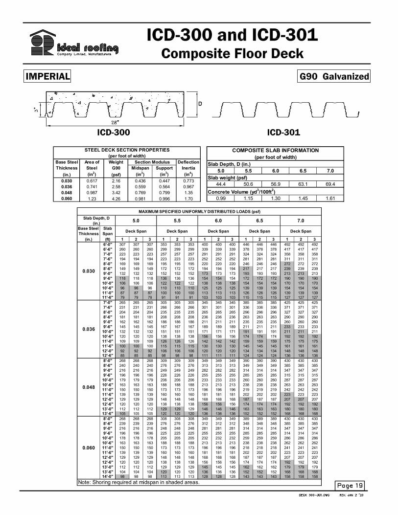
Base Steel Area of Weight Deflection
Thickness Steel G90 Midspan Support Inertia 4.0 4.5 5.0 5.5 6.0
(in.) (in.2) (psf) (in.3) (in.3) (in.4)
0.030 0.481 1.69 0.189 0.193 0.167 41.0 47.3 53.5 59.8 66.0
0.036 0.577 2.02 0.230 0.242 0.208
0.048 0.769 2.67 0.313 0.319 0.288 0.95 1.10 1.26 1.41 1.56
(per foot of width)
COMPOSITE SLAB SECTION PROPERTIES
(per foot of width)
Concrete Volume (yd3/100ft2)
STEEL PROFILE SECTION PROPERTIES
Section Modulus Slab Depth, D (in.)
Slab weight (psf)
Base Steel Slab
Thickness Span
(in.) (ft) 1 2 3 1 2 3 1 2 3 1 2 3 1 2 3
5'- 0" 500 500 500 581 581 581 662 662 662 743 743 743 823 823 823
5'- 6" 423 423 423 491 491 491 560 560 560 628 628 628 696 696 696
6'- 0" 364 364 364 422 422 422 481 481 481 540 540 540 599 599 599
6'- 6" 317 317 317 368 368 368 419 419 419 470 470 470 521 521 521
7'- 0" 279 279 279 324 324 324 369 369 369 414 414 414 459 459 459
7'- 6" 248 248 248 289 289 289 329 329 329 369 369 369 409 409 409
8'- 0" 223 223 223 259 259 259 295 295 295 331 331 331 367 367 367
8'- 6" 202 202 202 234 234 234 267 267 267 299 299 299 332 332 332
9'- 0" 178 178 178 212 212 212 243 243 243 272 272 272 302 302 302
9'- 6" 156 156 156 186 186 186 216 216 216 246 246 246 276 276 276
10'- 0" 138 138 138 164 164 164 191 191 191 217 217 217 244 244 244
5'- 0" 546 546 546 634 634 634 722 722 722 810 810 810 898 898 898
5'- 6" 467 467 467 543 543 543 618 618 618 694 694 694 769 769 769
6'- 0" 406 406 406 472 472 472 537 537 537 603 603 603 669 669 669
6'- 6" 358 358 358 415 415 415 473 473 473 531 531 531 589 589 589
7'- 0" 318 318 318 370 370 370 421 421 421 473 473 473 524 524 524
7'- 6" 286 286 286 332 332 332 379 379 379 425 425 425 471 471 471
8'- 0" 259 259 259 301 301 301 343 343 343 385 385 385 427 427 427
8'- 6" 236 236 236 274 274 274 313 313 313 351 351 351 389 389 389
9'- 0" 212 212 212 252 252 252 287 287 287 322 322 322 357 357 357
9'- 6" 187 187 187 224 224 224 261 261 261 297 297 297 329 329 329
10'- 0" 165 165 165 198 198 198 231 231 231 264 264 264 297 297 297
5'- 0" 600 600 600 697 697 697 795 795 795 892 892 892 989 989 989
5'- 6" 522 522 522 607 607 607 691 691 691 776 776 776 860 860 860
6'- 0" 461 461 461 536 536 536 610 610 610 685 685 685 759 759 759
6'- 6" 411 411 411 478 478 478 545 545 545 611 611 611 678 678 678
7'- 0" 371 371 371 431 431 431 491 491 491 551 551 551 611 611 611
7'- 6" 337 337 337 392 392 392 447 447 447 501 501 501 556 556 556
8'- 0" 309 309 309 359 359 359 409 409 409 459 459 459 509 509 509
8'- 6" 285 285 285 331 331 331 377 377 377 423 423 423 469 469 469
9'- 0" 264 264 264 306 306 306 349 349 349 392 392 392 434 434 434
9'- 6" 241 241 241 285 285 285 325 325 325 365 365 365 404 404 404
10'- 0" 210 210 210 259 259 259 304 304 304 341 341 341 378 378 378
Note: Shoring required at midspan in shaded areas.
Slab Depth, D
(in.)
Deck Span Deck Span
4.0 4.5
0.036
0.048
Deck Span
MAXIMUM SPECIFIED UNIFORMLY DISTRIBUTED LOADS (psf)
5.5 6.0
0.030
Deck Span Deck Span
5.0

TECHNICAL NOTES
Material Properties
1. The composite steel deck ICD-150 is the IRD-150 roof deck with embossments rolled into the web elements to achieve the composite interlocking capacity between the steel deck and concrete.
2. Steel deck section properties were calculated in accordance with CSA S136-01 (Supplement 2004).
3. Steel conforms to ASTM A653 SS Grade 33 and A653M SS Grade 230 with Z275 (G90) and ZF75 (A25) surface coatings.
4. Concrete is based on normal density of 2300 kg/m
3 (145 pcf) and having a minimum
compressive strength of 20 MPa (3 ksi).
Load Tables
1. Loads are maximum specified uniformly distributed loads resulting from human occupancy and should not be used for concentrated loads. Maximum specified load from load table must be
≥ [LL + 0.833DL]; Where LL = specified live load; DL = specified dead load; 0.833 = 1.25/1.5
2. Loads greater than 10 kPa (200 psf) are commonly
the result of large concentrated moving loads.
In such cases, appropriate design consideration
should be used by the structural engineers.
3. The ICD-150 steel deck provides the positive reinforcement for the simply supported composite slab and no additional reinforcing steel is required. To control shrinkage and temperature cracking,
a minimum steel wire mesh of 152 x 152 – MW9.1/MW9.1 (6 x 6 - 10/10) is recommended as per CSSBI S3-03.
4. Shoring requirements shown in shaded areas of the load table were established in accordance with CSSBI 12M-06.
5. To establish the shear-bond capacity of the composite slab system, laboratory tests were carried out at the Structural Testing and Research laboratory (STAR), Cambridge, Ontario in accordance with CSSBI S2-02.
6. All technical information and load tables were prepared by Dr. R.M. Schuster, Professor Emeritus of Structural Engineering, University of Waterloo, Ontario.
EXAMPLE (Imperial)
Determine the specified uniformly distributed live load that can be placed on the composite floor slab, given the following information: Given:
• Steel deck thickness = 0.048 in.
• Yield strength = 33 ksi
• Normal density concrete = 145 lb/ft3
• Overall slab depth = 4.5 in.
• Double span, each = 10 ft
• Specified superimposed dead load, DL = 32 psf
Solution:
The maximum specified load in (psf) from load table
must be ≥ [LL + (1.25/1.5)DL],
where LL = specified live load DL = specified superimposed dead load From load table under 10 ft span, the maximum specified load is 259 psf, therefore,
259 ≥ [LL + (1.25/1.5)32] and solving for LL,
LL = 232 psf Since this is in the shaded area, one shore support is required at mid-span in each span. Note: -The self-weight of the steel deck and concrete slab
have already been accounted for in the maximum specified uniformly distributed load given in the composite slab load table. -Minimum Bearing Length “n” at end support is
1.5 x height of deck = 2.25”. -At middle support use n=4”.

Base Steel Area of Mass Deflection
Thickness Steel Z275 Midspan Support Inertia 100 110 120 130 140
(mm) (mm2) (kg/m2) (x103mm3) (x103mm3) (x106mm4)
0.762 1017 8.26 10.2 10.4 0.236 1.88 2.11 2.33 2.56 2.78
0.914 1221 9.86 12.4 13.0 0.293
1.22 1628 13.1 16.9 17.2 0.397 0.76 0.86 0.96 1.06 1.16
(per metre of width)
COMPOSITE SLAB SECTION PROPERTIES
(per metre of width)
Concrete Volume (m3/10m2)
STEEL PROFILE SECTION PROPERTIES
Section Modulus Slab Depth, D (mm)
Slab weight (kPa)
Base Steel Slab
Thickness Span
(mm) (m) 1 2 3 1 2 3 1 2 3 1 2 3 1 2 3
1.5 24.2 24.2 24.2 27.3 27.3 27.3 30.4 30.4 30.4 33.6 33.6 33.6 36.7 36.7 36.7
1.6 21.6 21.6 21.6 24.4 24.4 24.4 27.2 27.2 27.2 30.0 30.0 30.0 32.8 32.8 32.8
1.8 17.6 17.6 17.6 19.8 19.8 19.8 22.1 22.1 22.1 24.4 24.4 24.4 26.7 26.7 26.7
2.0 14.6 14.6 14.6 16.5 16.5 16.5 18.4 18.4 18.4 20.3 20.3 20.3 22.2 22.2 22.2
2.2 12.4 12.4 12.4 14.1 14.1 14.1 15.7 15.7 15.7 17.3 17.3 17.3 18.9 18.9 18.9
2.4 10.8 10.8 10.8 12.1 12.1 12.1 13.5 13.5 13.5 14.9 14.9 14.9 16.3 16.3 16.3
2.5 10.0 10.0 10.0 11.3 11.3 11.3 12.7 12.7 12.7 14.0 14.0 14.0 15.3 15.3 15.3
2.6 9.4 9.4 9.4 10.6 10.6 10.6 11.9 11.9 11.9 13.1 13.1 13.1 14.3 14.3 14.3
2.8 8.0 8.0 8.0 9.2 9.2 9.2 10.5 10.5 10.5 11.6 11.6 11.6 12.7 12.7 12.7
3.0 6.8 6.8 6.8 7.8 7.8 7.8 8.9 8.9 8.9 10.0 10.0 10.0 11.0 11.0 11.0
3.2 5.8 5.8 5.8 6.7 6.7 6.7 7.6 7.6 7.6 8.5 8.5 8.5 9.4 9.4 9.4
1.5 26.2 26.2 26.2 29.6 29.6 29.6 33.0 33.0 33.0 36.4 36.4 36.4 39.8 39.8 39.8
1.6 23.6 23.6 23.6 26.6 26.6 26.6 29.7 29.7 29.7 32.8 32.8 32.8 35.8 35.8 35.8
1.8 19.5 19.5 19.5 22.0 22.0 22.0 24.6 24.6 24.6 27.1 27.1 27.1 29.6 29.6 29.6
2.0 16.5 16.5 16.5 18.6 18.6 18.6 20.8 20.8 20.8 22.9 22.9 22.9 25.1 25.1 25.1
2.2 14.2 14.2 14.2 16.1 16.1 16.1 17.9 17.9 17.9 19.7 19.7 19.7 21.6 21.6 21.6
2.4 12.4 12.4 12.4 14.0 14.0 14.0 15.7 15.7 15.7 17.3 17.3 17.3 18.9 18.9 18.9
2.5 11.7 11.7 11.7 13.2 13.2 13.2 14.7 14.7 14.7 16.2 16.2 16.2 17.7 17.7 17.7
2.6 11.0 11.0 11.0 12.4 12.4 12.4 13.9 13.9 13.9 15.3 15.3 15.3 16.7 16.7 16.7
2.8 9.5 9.5 9.5 11.0 11.0 11.0 12.4 12.4 12.4 13.7 13.7 13.7 15.0 15.0 15.0
3.0 8.1 8.1 8.1 9.4 9.4 9.4 10.7 10.7 10.7 12.0 12.0 12.0 13.3 13.3 13.3
3.2 6.9 6.9 6.9 8.1 8.1 8.1 9.2 9.2 9.2 10.3 10.3 10.3 11.4 11.4 11.4
1.5 28.8 28.8 28.8 32.5 32.5 32.5 36.2 36.2 36.2 40.0 40.0 40.0 43.7 43.7 43.7
1.6 26.2 26.2 26.2 29.6 29.6 29.6 33.0 33.0 33.0 36.4 36.4 36.4 39.8 39.8 39.8
1.8 22.1 22.1 22.1 24.9 24.9 24.9 27.8 27.8 27.8 30.7 30.7 30.7 33.5 33.5 33.5
2.0 19.0 19.0 19.0 21.5 21.5 21.5 24.0 24.0 24.0 26.4 26.4 26.4 28.9 28.9 28.9
2.2 16.6 16.6 16.6 18.8 18.8 18.8 21.0 21.0 21.0 23.1 23.1 23.1 25.3 25.3 25.3
2.4 14.8 14.8 14.8 16.7 16.7 16.7 18.6 18.6 18.6 20.5 20.5 20.5 22.5 22.5 22.5
2.5 14.0 14.0 14.0 15.8 15.8 15.8 17.6 17.6 17.6 19.4 19.4 19.4 21.3 21.3 21.3
2.6 13.3 13.3 13.3 15.0 15.0 15.0 16.7 16.7 16.7 18.4 18.4 18.4 20.2 20.2 20.2
2.8 12.0 12.0 12.0 13.6 13.6 13.6 15.1 15.1 15.1 16.7 16.7 16.7 18.3 18.3 18.3
3.0 9.9 9.9 9.9 12.2 12.2 12.2 13.8 13.8 13.8 15.2 15.2 15.2 16.7 16.7 16.7
3.2 8.2 8.2 8.2 10.5 10.5 10.5 12.1 12.1 12.1 13.6 13.6 13.6 15.2 15.2 15.2
MAXIMUM SPECIFIED UNIFORMLY DISTRIBUTED LOADS (kPa)
Slab Depth, D100 110 120 130 140
(mm)
Note: Shoring required at midspan in shaded areas.
Deck Span
0.762
0.914
1.22
Deck Span Deck Span Deck Span Deck Span

TECHNICAL NOTES
Material Properties
1. The composite steel deck ICD-150 is the IRD-150 roof deck with embossments rolled into the web elements to achieve the composite interlocking capacity between the steel deck and concrete.
2. Steel deck section properties were calculated in accordance with CSA S136-01 (Supplement 2004).
3. Steel conforms to ASTM A653 SS Grade 33 and A653M SS Grade 230 with Z275 (G90) and ZF75 (A25) surface coatings.
4. Concrete is based on normal density of 2300 kg/m
3 (145 pcf) and having a minimum
compressive strength of 20 MPa (3 ksi).
Load Tables
1. Loads are maximum specified uniformly distributed loads resulting from human occupancy and should not be used for concentrated loads. Maximum specified load from load table must be
≥ [LL + 0.833DL]; Where LL = specified live load; DL = specified dead load; 0.833 = 1.25/1.5
2. Loads greater than 10 kPa (200 psf) are commonly
the result of large concentrated moving loads.
In such cases, appropriate design consideration
should be used by the structural engineers.
3. The ICD-150 steel deck provides the positive reinforcement for the simply supported composite slab and no additional reinforcing steel is required. To control shrinkage and temperature cracking,
a minimum steel wire mesh of 152 x 152 – MW9.1/MW9.1 (6 x 6 - 10/10) is recommended as per CSSBI S3-03.
4. Shoring requirements shown in shaded areas of the load table were established in accordance with CSSBI 12M-06.
5. To establish the shear-bond capacity of the composite slab system, laboratory tests were carried out at the Structural Testing and Research laboratory (STAR), Cambridge, Ontario in accordance with CSSBI S2-02.
6. All technical information and load tables were prepared by Dr. R.M. Schuster, Professor Emeritus of Structural Engineering, University of Waterloo, Ontario.
EXAMPLE (Metric)
Determine the specified uniformly distributed live load that can be placed on the composite floor slab, given the following information: Given:
• Steel deck thickness = 1.22 mm
• Yield strength = 230 MPa
• Normal density concrete = 2300 kg/m3
• Overall slab depth = 120 mm
• Double span, each = 3.0 m
• Specified superimposed dead load, DL = 1.55 kPa
Solution:
The maximum specified load in (kPa) from load table
must be ≥ [LL + (1.25/1.5)DL],
where LL = specified live load DL = specified superimposed dead load From load table under 3.0 m span, the maximum
specified load is 13.8 kPa, therefore,
13.8 ≥ [LL + (1.25/1.5)1.55] and solving for LL,
LL = 12.5 kPa Since this is in the shaded area, one shore support is required at mid-span in each span.
Note: -The self-weight of the steel deck and concrete slab
have already been accounted for in the maximum specified uniformly distributed load given in the
composite slab load table.
-Minimum Bearing Length “n” at end support is 1.5 x height of deck = 57mm
-At middle support use n=100mm.

Base Steel Area of Weight Deflection
Thickness Steel G90 Midspan Support Inertia 4.0 4.5 5.0 5.5 6.0
(in.) (in.2) (psf) (in.3) (in.3) (in.4)
0.030 0.481 1.69 0.193 0.189 0.183 45.5 51.8 58.0 64.3 70.5
0.036 0.577 2.02 0.242 0.230 0.219
0.048 0.769 2.67 0.319 0.313 0.291 1.06 1.21 1.37 1.52 1.68
(per foot of width)
COMPOSITE SLAB SECTION PROPERTIES
(per foot of width)
Concrete Volume (yd3/100ft2)
STEEL PROFILE SECTION PROPERTIES
Section Modulus Slab Depth, D (in.)
Slab weight (psf)
Base Steel Slab
Thickness Span
(in.) (ft) 1 2 3 1 2 3 1 2 3 1 2 3 1 2 3
5'- 0" 401 401 401 461 461 461 520 520 520 580 580 580 639 639 639
5'- 6" 338 338 338 389 389 389 439 439 439 489 489 489 539 539 539
6'- 0" 290 290 290 333 333 333 376 376 376 419 419 419 462 462 462
6'- 6" 252 252 252 289 289 289 327 327 327 364 364 364 401 401 401
7'- 0" 221 221 221 254 254 254 287 287 287 320 320 320 353 353 353
7'- 6" 196 196 196 226 226 226 255 255 255 284 284 284 313 313 313
8'- 0" 176 176 176 202 202 202 228 228 228 254 254 254 280 280 280
8'- 6" 159 159 159 182 182 182 206 206 206 229 229 229 253 253 253
9'- 0" 144 144 144 165 165 165 187 187 187 208 208 208 229 229 229
9'- 6" 132 132 132 151 151 151 171 171 171 190 190 190 210 210 210
10'- 0" 121 121 121 139 139 139 157 157 157 174 174 174 192 192 192
5'- 0" 454 454 454 521 521 521 589 589 589 656 656 656 724 724 724
5'- 6" 383 383 383 440 440 440 497 497 497 554 554 554 610 610 610
6'- 0" 328 328 328 377 377 377 426 426 426 475 475 475 523 523 523
6'- 6" 285 285 285 328 328 328 370 370 370 412 412 412 455 455 455
7'- 0" 251 251 251 288 288 288 325 325 325 363 363 363 400 400 400
7'- 6" 223 223 223 256 256 256 289 289 289 322 322 322 355 355 355
8'- 0" 199 199 199 229 229 229 259 259 259 288 288 288 318 318 318
8'- 6" 180 180 180 207 207 207 233 233 233 260 260 260 287 287 287
9'- 0" 163 163 163 188 188 188 212 212 212 236 236 236 260 260 260
9'- 6" 149 149 149 171 171 171 194 194 194 216 216 216 238 238 238
10'- 0" 137 137 137 157 157 157 178 178 178 198 198 198 218 218 218
5'- 0" 535 535 535 615 615 615 694 694 694 774 774 774 853 853 853
5'- 6" 452 452 452 519 519 519 586 586 586 653 653 653 720 720 720
6'- 0" 387 387 387 445 445 445 503 503 503 560 560 560 618 618 618
6'- 6" 337 337 337 387 387 387 437 437 437 487 487 487 537 537 537
7'- 0" 296 296 296 340 340 340 384 384 384 428 428 428 472 472 472
7'- 6" 263 263 263 302 302 302 341 341 341 380 380 380 420 420 420
8'- 0" 236 236 236 271 271 271 306 306 306 341 341 341 376 376 376
8'- 6" 213 213 213 244 244 244 276 276 276 308 308 308 339 339 339
9'- 0" 193 193 193 222 222 222 251 251 251 280 280 280 308 308 308
9'- 6" 177 177 177 203 203 203 229 229 229 255 255 255 282 282 282
10'- 0" 162 162 162 186 186 186 211 211 211 235 235 235 259 259 259
Note: Shoring required at midspan in shaded areas.
Slab Depth, D
(in.)
Deck Span Deck Span
4.0 4.5
0.036
0.048
Deck Span
MAXIMUM SPECIFIED UNIFORMLY DISTRIBUTED LOADS (psf)
5.5 6.0
0.030
Deck Span Deck Span
5.0

TECHNICAL NOTES
Material Properties
1. The ICD-150 (INVERTED) is the IRD-150 roof deck with embossments rolled into the web elements to achieve the composite interlocking capacity between the steel deck and concrete.
2. Steel deck section properties were calculated in accordance with CSA S136-07.
3. Steel conforms to ASTM A653 SS Grade 33 and A653M SS Grade 230 with Z275 (G90) and ZF75 (A25) surface coatings.
4. Concrete is based on normal density of 2300 kg/m
3 (145 pcf) and having a minimum
compressive strength of 20 MPa (3 ksi).
Load Tables
1. Loads are maximum specified uniformly distributed loads resulting from human occupancy and should not be used for concentrated loads. Maximum specified load from load table must be
≥ [LL + 0.833DL]; Where LL = specified live load; DL = specified dead load; 0.833 = 1.25/1.5
2. Loads greater than 10 kPa (200 psf) are commonly
the result of large concentrated moving loads.
In such cases, appropriate design consideration
should be used by the structural engineers.
3. The ICD-150 steel deck provides the positive reinforcement for the simply supported composite slab and no additional reinforcing steel is required. To control shrinkage and temperature cracking, a minimum steel wire mesh of 152 x 152 – MW9.1/MW9.1
(6 x 6 - 10/10) is recommended as per CSSBI S3-03.
4. Shoring requirements shown in shaded areas of the load table were established in accordance with CSSBI 12M-06.
5. To establish the shear-bond capacity of the IDEAL inverted composite slab system, laboratory tests were carried out at the Structural Testing and Research laboratory (STAR), Cambridge, Ontario in accordance with CSSBI S2-02.
6. All technical information and load tables were prepared by Dr. R.M. Schuster, Professor Emeritus of Structural Engineering, University of Waterloo, Ontario.
EXAMPLE (Imperial)
Determine the specified uniformly distributed live load that can be placed on the IDEAL inverted composite floor slab, given the following information: Given:
• Steel deck thickness = 0.048 in.
• Yield strength = 33 ksi
• Normal density concrete = 145 lb/ft3
• Overall slab depth = 5.0 in.
• Double span, each = 9.5 ft
• Specified superimposed dead load, DL = 37 psf
Solution:
The maximum specified load in (psf) from load table
must be ≥ [LL + (1.25/1.5)DL],
where LL = specified live load DL = specified superimposed dead load From load table under 9.5 ft span, the maximum
specified load is 229 psf, therefore,
229 ≥ [LL + (1.25/1.5)32] and solving for LL,
LL = 198 psf Since this is in the shaded area, one shore support is required at mid-span in each span. Note: -The self-weight of the steel deck and concrete slab
have already been accounted for in the maximum specified uniformly distributed load given in the composite slab load table. -Minimum Bearing Length “n” at end support is
1.5 x height of deck = 2.25”. -At middle support use n=4”.

Base Steel Area of Mass Deflection
Thickness Steel Z275 Midspan Support Inertia 100 110 120 130 140
(mm) (mm2) (kg/m2) (x103mm3) (x103mm3) (x106mm4)
0.762 1017 8.26 10.4 10.2 0.250 2.06 2.28 2.51 2.73 2.96
0.914 1221 9.86 13.0 12.4 0.299
1.22 1628 13.1 17.2 16.9 0.397 0.86 0.96 1.06 1.16 1.26
(per metre of width)
COMPOSITE SLAB SECTION PROPERTIES
(per metre of width)
Concrete Volume (m3/10m2)
STEEL PROFILE SECTION PROPERTIES
Section Modulus Slab Depth, D (mm)
Slab weight (kPa)
Base Steel Slab
Thickness Span
(mm) (m) 1 2 3 1 2 3 1 2 3 1 2 3 1 2 3
1.5 19.4 19.4 19.4 21.7 21.7 21.7 24.0 24.0 24.0 26.3 26.3 26.3 28.6 28.6 28.6
1.6 17.3 17.3 17.3 19.3 19.3 19.3 21.4 21.4 21.4 23.4 23.4 23.4 25.5 25.5 25.5
1.8 14.0 14.0 14.0 15.7 15.7 15.7 17.3 17.3 17.3 19.0 19.0 19.0 20.7 20.7 20.7
2.0 11.6 11.6 11.6 13.0 13.0 13.0 14.4 14.4 14.4 15.8 15.8 15.8 17.2 17.2 17.2
2.2 9.9 9.9 9.9 11.0 11.0 11.0 12.2 12.2 12.2 13.4 13.4 13.4 14.6 14.6 14.6
2.4 8.5 8.5 8.5 9.5 9.5 9.5 10.5 10.5 10.5 11.5 11.5 11.5 12.5 12.5 12.5
2.5 7.9 7.9 7.9 8.9 8.9 8.9 9.8 9.8 9.8 10.7 10.7 10.7 11.7 11.7 11.7
2.6 7.4 7.4 7.4 8.3 8.3 8.3 9.2 9.2 9.2 10.1 10.1 10.1 10.9 10.9 10.9
2.8 6.5 6.5 6.5 7.3 7.3 7.3 8.1 8.1 8.1 8.9 8.9 8.9 9.6 9.6 9.6
3.0 5.8 5.8 5.8 6.5 6.5 6.5 7.2 7.2 7.2 7.9 7.9 7.9 8.6 8.6 8.6
3.2 5.2 5.2 5.2 5.9 5.9 5.9 6.5 6.5 6.5 7.1 7.1 7.1 7.7 7.7 7.7
1.5 21.9 21.9 21.9 24.5 24.5 24.5 27.1 27.1 27.1 29.8 29.8 29.8 32.4 32.4 32.4
1.6 19.5 19.5 19.5 21.9 21.9 21.9 24.2 24.2 24.2 26.5 26.5 26.5 28.8 28.8 28.8
1.8 15.9 15.9 15.9 17.7 17.7 17.7 19.6 19.6 19.6 21.5 21.5 21.5 23.4 23.4 23.4
2.0 13.2 13.2 13.2 14.7 14.7 14.7 16.3 16.3 16.3 17.9 17.9 17.9 19.5 19.5 19.5
2.2 11.2 11.2 11.2 12.5 12.5 12.5 13.8 13.8 13.8 15.2 15.2 15.2 16.5 16.5 16.5
2.4 9.6 9.6 9.6 10.8 10.8 10.8 11.9 11.9 11.9 13.1 13.1 13.1 14.2 14.2 14.2
2.5 9.0 9.0 9.0 10.0 10.0 10.0 11.1 11.1 11.1 12.2 12.2 12.2 13.3 13.3 13.3
2.6 8.4 8.4 8.4 9.4 9.4 9.4 10.4 10.4 10.4 11.4 11.4 11.4 12.4 12.4 12.4
2.8 7.4 7.4 7.4 8.3 8.3 8.3 9.2 9.2 9.2 10.1 10.1 10.1 10.9 10.9 10.9
3.0 6.6 6.6 6.6 7.4 7.4 7.4 8.2 8.2 8.2 9.0 9.0 9.0 9.8 9.8 9.8
3.2 5.9 5.9 5.9 6.6 6.6 6.6 7.4 7.4 7.4 8.1 8.1 8.1 8.8 8.8 8.8
1.5 25.9 25.9 25.9 29.0 29.0 29.0 32.0 32.0 32.0 35.1 35.1 35.1 38.2 38.2 38.2
1.6 23.1 23.1 23.1 25.8 25.8 25.8 28.6 28.6 28.6 31.3 31.3 31.3 34.1 34.1 34.1
1.8 18.7 18.7 18.7 21.0 21.0 21.0 23.2 23.2 23.2 25.4 25.4 25.4 27.7 27.7 27.7
2.0 15.6 15.6 15.6 17.4 17.4 17.4 19.3 19.3 19.3 21.1 21.1 21.1 23.0 23.0 23.0
2.2 13.2 13.2 13.2 14.8 14.8 14.8 16.4 16.4 16.4 17.9 17.9 17.9 19.5 19.5 19.5
2.4 11.4 11.4 11.4 12.7 12.7 12.7 14.1 14.1 14.1 15.5 15.5 15.5 16.8 16.8 16.8
2.5 10.6 10.6 10.6 11.9 11.9 11.9 13.1 13.1 13.1 14.4 14.4 14.4 15.7 15.7 15.7
2.6 9.9 9.9 9.9 11.1 11.1 11.1 12.3 12.3 12.3 13.5 13.5 13.5 14.7 14.7 14.7
2.8 8.8 8.8 8.8 9.8 9.8 9.8 10.9 10.9 10.9 11.9 11.9 11.9 13.0 13.0 13.0
3.0 7.8 7.8 7.8 8.8 8.8 8.8 9.7 9.7 9.7 10.6 10.6 10.6 11.6 11.6 11.6
3.2 7.0 7.0 7.0 7.9 7.9 7.9 8.7 8.7 8.7 9.6 9.6 9.6 10.4 10.4 10.4
Note: Shoring required at midspan in shaded areas.
Deck Span
0.762
0.914
1.22
Deck Span Deck Span Deck Span Deck Span
MAXIMUM SPECIFIED UNIFORMLY DISTRIBUTED LOADS (kPa)
Slab Depth, D100 110 120 130 140
(mm)

TECHNICAL NOTES
Material Properties
1. The ICD-150 (INVERTED) is the IRD-150 roof deck with embossments rolled into the web elements to achieve the composite interlocking capacity between the steel deck and concrete.
2. Steel deck section properties were calculated in accordance with CSA S136-07.
3. Steel conforms to ASTM A653 SS Grade 33 and A653M SS Grade 230 with Z275 (G90) and ZF75 (A25) surface coatings.
4. Concrete is based on normal density of 2300 kg/m
3 (145 pcf) and having a minimum
compressive strength of 20 MPa (3 ksi).
Load Tables
1. Loads are maximum specified uniformly distributed loads resulting from human occupancy and should not be used for concentrated loads. Maximum specified load from load table must be
≥ [LL + 0.833DL]; Where LL = specified live load; DL = specified dead load; 0.833 = 1.25/1.5
2. Loads greater than 10 kPa (200 psf) are commonly
the result of large concentrated moving loads.
In such cases, appropriate design consideration
should be used by the structural engineers.
3. The ICD-150 steel deck provides the positive reinforcement for the simply supported composite slab and no additional reinforcing steel is required. To control shrinkage and temperature cracking, a minimum steel wire mesh of 152 x 152 – MW9.1/MW9.1
(6 x 6 - 10/10) is recommended as per CSSBI S3-03.
4. Shoring requirements shown in shaded areas of the load table were established in accordance with CSSBI 12M-06.
5. To establish the shear-bond capacity of the IDEAL inverted composite slab system, laboratory tests were carried out at the Structural Testing and Research laboratory (STAR), Cambridge, Ontario in accordance with CSSBI S2-02.
6. All technical information and load tables were prepared by Dr. R.M. Schuster, Professor Emeritus of Structural Engineering, University of Waterloo, Ontario.
EXAMPLE (Metric)
Determine the specified uniformly distributed live load
that can be placed on the IDEAL inverted composite floor slab, given the following information:
Given:
• Steel deck thickness = 1.22 mm
• Yield strength = 230 MPa
• Normal density concrete = 2300 kg/m3
• Overall slab depth = 130 mm
• Double span, each = 2.8 m
• Specified superimposed dead load, DL = 1.70 kPa
Solution:
The maximum specified load in (kPa) from load table
must be ≥ [LL + (1.25/1.5)DL],
where LL = specified live load DL = specified superimposed dead load From load table under 2.8 m span, the maximum specified load is 11.9 kPa, therefore,
11.9 ≥ [LL + (1.25/1.5)1.70] and solving for LL,
LL = 10.5 kPa Since this is in the shaded area, one shore support is required at mid-span in each span. Note:
-The self-weight of the steel deck and concrete slab have already been accounted for in the maximum
specified uniformly distributed load given in the composite slab load table.
-Minimum Bearing Length “n” at end support is
1.5 x height of deck = 57mm -At middle support use n=100mm.
5.0 5.5 6.0 6.5 7.0
44.4 50.6 56.9 63.1 69.4
Concrete Volume (yd3/100ft
2)
0.99 1.15 1.30 1.45 1.61
(per foot of width)
COMPOSITE SLAB INFORMATION
Slab Depth, D (in.)
Slab weight (psf)
Base Steel Area of Weight Deflection
Thickness Steel G90 Midspan Support Inertia
(in.) (in2) (psf) (in
3) (in
3) (in
4)
0.030 0.617 2.16 0.436 0.447 0.773
0.036 0.741 2.58 0.559 0.564 0.967
0.048 0.987 3.42 0.769 0.799 1.35
0.060 1.23 4.26 0.981 0.996 1.70
(per foot of width)
STEEL DECK SECTION PROPERTIES
Section Modulus
Base Steel Slab
Thickness Span
(in.) (ft) 1 2 3 1 2 3 1 2 3 1 2 3 1 2 3
6'-0" 307 307 307 353 353 353 400 400 400 446 446 446 492 492 492
6'-6" 260 260 260 299 299 299 339 339 339 378 378 378 417 417 417
7'-0" 223 223 223 257 257 257 291 291 291 324 324 324 358 358 358
7'-6" 194 194 194 223 223 223 252 252 252 281 281 281 311 311 311
8'-0" 169 169 169 195 195 195 220 220 220 246 246 246 272 272 272
8'-6" 149 149 149 172 172 172 194 194 194 217 217 217 239 239 239
9'-0" 132 132 132 152 152 152 173 173 173 193 193 193 213 213 213
9'-6" 118 118 118 136 136 136 154 154 154 172 172 172 190 190 190
10'-0" 106 106 106 122 122 122 138 138 138 154 154 154 170 170 170
10'-6" 96 96 96 110 110 110 125 125 125 139 139 139 154 154 154
11'-0" 87 87 87 100 100 100 113 113 113 126 126 126 139 139 139
11'-6" 79 79 79 91 91 91 103 103 103 115 115 115 127 127 127
7'-0" 265 265 265 305 305 305 345 345 345 385 385 385 425 425 425
7'-6" 231 231 231 266 266 266 301 301 301 336 336 336 371 371 371
8'-0" 204 204 204 235 235 235 265 265 265 296 296 296 327 327 327
8'-6" 181 181 181 208 208 208 236 236 236 263 263 263 290 290 290
9'-0" 162 162 162 186 186 186 211 211 211 235 235 235 260 260 260
9'-6" 145 145 145 167 167 167 189 189 189 211 211 211 233 233 233
10'-0" 132 132 132 151 151 151 171 171 171 191 191 191 211 211 211
10'-6" 120 120 120 138 138 138 156 156 156 174 174 174 192 192 192
11'-0" 109 109 109 126 126 126 142 142 142 159 159 159 175 175 175
11'-6" 100 100 100 115 115 115 130 130 130 145 145 145 161 161 161
12'-0" 92 92 92 106 106 106 120 120 120 134 134 134 148 148 148
12'-6" 85 85 85 98 98 98 111 111 111 124 124 124 136 136 136
8'-0" 268 268 268 309 309 309 349 349 349 390 390 390 430 430 430
8'-6" 240 240 240 276 276 276 313 313 313 349 349 349 385 385 385
9'-0" 216 216 216 249 249 249 282 282 282 314 314 314 347 347 347
9'-6" 196 196 196 226 226 226 255 255 255 285 285 285 315 315 315
10'-0" 179 179 179 206 206 206 233 233 233 260 260 260 287 287 287
10'-6" 163 163 163 188 188 188 213 213 213 238 238 238 263 263 263
11'-0" 150 150 150 173 173 173 196 196 196 219 219 219 242 242 242
11'-6" 139 139 139 160 160 160 181 181 181 202 202 202 223 223 223
12'-0" 129 129 129 148 148 148 168 168 168 187 187 187 207 207 207
12'-6" 120 120 120 138 138 138 156 156 156 174 174 174 192 192 192
13'-0" 112 112 112 129 129 129 146 146 146 163 163 163 180 180 180
13'-6" 105 105 105 120 120 120 136 136 136 152 152 152 168 168 168
8'-0" 268 268 268 308 308 308 349 349 349 389 389 389 430 430 430
8'-6" 239 239 239 276 276 276 312 312 312 348 348 348 385 385 385
9'-0" 216 216 216 248 248 248 281 281 281 314 314 314 347 347 347
9'-6" 196 196 196 225 225 225 255 255 255 285 285 285 314 314 314
10'-0" 178 178 178 205 205 205 232 232 232 259 259 259 286 286 286
10'-6" 163 163 163 188 188 188 213 213 213 238 238 238 262 262 262
11'-0" 150 150 150 173 173 173 196 196 196 218 218 218 241 241 241
11'-6" 139 139 139 160 160 160 181 181 181 202 202 202 223 223 223
12'-0" 129 129 129 148 148 148 168 168 168 187 187 187 207 207 207
12'-6" 120 120 120 138 138 138 156 156 156 174 174 174 192 192 192
13'-0" 112 112 112 129 129 129 145 145 145 162 162 162 179 179 179
13'-6" 104 104 104 120 120 120 136 136 136 152 152 152 168 168 168
14'-0" 98 98 98 113 113 113 128 128 128 143 143 143 158 158 158
Note: Shoring required at midspan in shaded areas.
Deck SpanDeck Span Deck Span
5.0 5.5
0.036
(in.)
0.048
0.060
MAXIMUM SPECIFIED UNIFORMLY DISTRIBUTED LOADS (psf)
6.5 7.0
0.030
Deck Span Deck Span
6.0Slab Depth, D

TECHNICAL NOTES
Material Properties
1. The composite steel deck ICD-300 is the IRD-300 roof deck with embossments rolled into the web elements to achieve the composite interlocking capacity between the steel deck and concrete.
2. Steel deck section properties were calculated in accordance with CSA S136-07.
3. Steel conforms to ASTM A653 SS Grade 33 and A653M SS Grade 230 with Z275 (G90) and ZF75 (A25) surface coatings.
4. Concrete is based on normal density of 2300 kg/m
3 (145 pcf) and having a minimum
compressive strength of 20 MPa (3 ksi).
Load Tables
1. Loads are maximum specified uniformly distributed loads resulting from human occupancy and should not be used for concentrated loads. Maximum specified load from load table must be
≥ [LL + 0.833DL]; Where LL = specified live load; DL = specified dead load; 0.833 = 1.25/1.5
2. Loads greater than 10 kPa (200 psf) are commonly
the result of large concentrated moving loads.
In such cases, appropriate design consideration
should be used by the structural engineers.
3. The ICD-300 steel deck provides the positive reinforcement for the simply supported composite slab and no additional reinforcing steel is required. To control shrinkage and temperature cracking,
a minimum steel wire mesh of 152 x 152 – MW9.1/MW9.1 (6 x 6 - 10/10) is recommended as per CSSBI S3-08.
4. Shoring requirements shown in shaded areas of the load table were established in accordance with CSSBI 12M-08.
5. To establish the shear-bond capacity of the ICD-
300 composite slab system, laboratory tests were carried out at the Structural Testing and Research laboratory (STAR), Cambridge, Ontario in accordance with CSSBI S2-08.
6. All technical information and load tables were prepared by Dr. R.M. Schuster, Professor Emeritus of Structural Engineering, University of Waterloo, Ontario.
EXAMPLE (Imperial)
Determine the specified uniformly distributed live load that can be placed on the composite floor slab, given the following information: Given:
• Steel deck thickness = 0.036 in.
• Yield strength = 33 ksi
• Normal density concrete = 145 lb/ft3
• Overall slab depth = 6 in.
• Double span, each = 11 ft
• Specified superimposed dead load, DL = 32 psf
Solution:
The maximum specified load in (psf) from load table
must be ≥ [LL + (1.25/1.5)DL],
where LL = specified live load DL = specified superimposed dead load From load table under 11 ft span, the maximum specified load is 142 psf, therefore,
142 ≥ [LL + (1.25/1.5)32] and solving for LL,
LL = 99 psf Since this is in the shaded area, one shore support is required at mid-span in each span. Note: -The self-weight of the steel deck and concrete slab
have already been accounted for in the maximum specified uniformly distributed load given in the composite slab load table. -Minimum Bearing Length “n” at end support is
1.5 x height of deck = 4.5”. -At middle support use n=6”.

130 140 150 160 170
2.11 2.34 2.56 2.79 3.01
Concrete Volume (m3/10m
2)
0.85 0.95 1.05 1.15 1.25
(per metre of width)
COMPOSITE SLAB INFORMATION
Slab Depth, D (mm)
Slab weight (kPa)
Base Steel Area of Mass Deflection
Thickness Steel Z275 Midspan Support Inertia
(mm) (mm2) (kg/m
2) (x10
3mm
3) (x10
3mm
3) (x10
6mm
4)
0.762 1306 10.5 23.4 24.0 1.05
0.914 1568 12.6 30.0 30.3 1.32
1.219 2090 16.7 41.3 42.9 1.84
1.524 2613 20.8 52.7 53.6 2.32
(per metre of width)
STEEL DECK SECTION PROPERTIES
Section Modulus
Base Steel Slab
Thickness Span
(mm) (m) 1 2 3 1 2 3 1 2 3 1 2 3 1 2 3
2.2 10.4 10.4 10.4 11.5 11.5 11.5 12.7 12.7 12.7 13.9 13.9 13.9 15.1 15.1 15.1
2.4 8.6 8.6 8.6 9.6 9.6 9.6 10.6 10.6 10.6 11.6 11.6 11.6 12.6 12.6 12.6
2.5 7.9 7.9 7.9 8.9 8.9 8.9 9.8 9.8 9.8 10.7 10.7 10.7 11.6 11.6 11.6
2.6 7.3 7.3 7.3 8.2 8.2 8.2 9.0 9.0 9.0 9.8 9.8 9.8 10.7 10.7 10.7
2.8 6.3 6.3 6.3 7.0 7.0 7.0 7.7 7.7 7.7 8.4 8.4 8.4 9.2 9.2 9.2
3.0 5.4 5.4 5.4 6.1 6.1 6.1 6.7 6.7 6.7 7.3 7.3 7.3 7.9 7.9 7.9
3.2 4.7 4.7 4.7 5.3 5.3 5.3 5.8 5.8 5.8 6.4 6.4 6.4 6.9 6.9 6.9
3.4 4.2 4.2 4.2 4.6 4.6 4.6 5.1 5.1 5.1 5.6 5.6 5.6 6.1 6.1 6.1
3.5 3.9 3.9 3.9 4.4 4.4 4.4 4.8 4.8 4.8 5.3 5.3 5.3 5.7 5.7 5.7
3.6 3.7 3.7 3.7 4.1 4.1 4.1 4.5 4.5 4.5 5.0 5.0 5.0 5.4 5.4 5.4
3.8 3.3 3.3 3.3 3.7 3.7 3.7 4.1 4.1 4.1 4.4 4.4 4.4 4.8 4.8 4.8
4.0 3.0 3.0 3.0 3.3 3.3 3.3 3.6 3.6 3.6 4.0 4.0 4.0 4.3 4.3 4.3
2.2 12.4 12.4 12.4 13.8 13.8 13.8 15.2 15.2 15.2 16.6 16.6 16.6 18.1 18.1 18.1
2.4 10.4 10.4 10.4 11.6 11.6 11.6 12.8 12.8 12.8 14.0 14.0 14.0 15.2 15.2 15.2
2.5 9.6 9.6 9.6 10.7 10.7 10.7 11.8 11.8 11.8 12.9 12.9 12.9 14.0 14.0 14.0
2.6 8.9 8.9 8.9 9.9 9.9 9.9 11.0 11.0 11.0 12.0 12.0 12.0 13.0 13.0 13.0
2.8 7.7 7.7 7.7 8.6 8.6 8.6 9.5 9.5 9.5 10.4 10.4 10.4 11.2 11.2 11.2
3.0 6.7 6.7 6.7 7.5 7.5 7.5 8.3 8.3 8.3 9.0 9.0 9.0 9.8 9.8 9.8
3.2 5.9 5.9 5.9 6.6 6.6 6.6 7.3 7.3 7.3 8.0 8.0 8.0 8.7 8.7 8.7
3.4 5.3 5.3 5.3 5.9 5.9 5.9 6.5 6.5 6.5 7.1 7.1 7.1 7.7 7.7 7.7
3.5 5.0 5.0 5.0 5.5 5.5 5.5 6.1 6.1 6.1 6.7 6.7 6.7 7.3 7.3 7.3
3.6 4.7 4.7 4.7 5.2 5.2 5.2 5.8 5.8 5.8 6.3 6.3 6.3 6.9 6.9 6.9
3.8 4.2 4.2 4.2 4.7 4.7 4.7 5.2 5.2 5.2 5.7 5.7 5.7 6.2 6.2 6.2
4.0 3.8 3.8 3.8 4.3 4.3 4.3 4.7 4.7 4.7 5.2 5.2 5.2 5.6 5.6 5.6
2.5 12.7 12.7 12.7 14.1 14.1 14.1 15.6 15.6 15.6 17.1 17.1 17.1 18.5 18.5 18.5
2.6 11.8 11.8 11.8 13.2 13.2 13.2 14.5 14.5 14.5 15.9 15.9 15.9 17.2 17.2 17.2
2.8 10.3 10.3 10.3 11.5 11.5 11.5 12.7 12.7 12.7 13.9 13.9 13.9 15.1 15.1 15.1
3.0 9.1 9.1 9.1 10.2 10.2 10.2 11.2 11.2 11.2 12.2 12.2 12.2 13.3 13.3 13.3
3.2 8.1 8.1 8.1 9.0 9.0 9.0 10.0 10.0 10.0 10.9 10.9 10.9 11.8 11.8 11.8
3.4 7.3 7.3 7.3 8.1 8.1 8.1 8.9 8.9 8.9 9.8 9.8 9.8 10.6 10.6 10.6
3.5 6.9 6.9 6.9 7.7 7.7 7.7 8.5 8.5 8.5 9.3 9.3 9.3 10.1 10.1 10.1
3.6 6.6 6.6 6.6 7.3 7.3 7.3 8.1 8.1 8.1 8.8 8.8 8.8 9.6 9.6 9.6
3.8 6.0 6.0 6.0 6.7 6.7 6.7 7.3 7.3 7.3 8.0 8.0 8.0 8.7 8.7 8.7
4.0 5.4 5.4 5.4 6.1 6.1 6.1 6.7 6.7 6.7 7.3 7.3 7.3 8.0 8.0 8.0
4.2 5.0 5.0 5.0 5.6 5.6 5.6 6.2 6.2 6.2 6.7 6.7 6.7 7.3 7.3 7.3
4.4 4.6 4.6 4.6 5.1 5.1 5.1 5.7 5.7 5.7 6.2 6.2 6.2 6.7 6.7 6.7
2.6 11.8 11.8 11.8 13.1 13.1 13.1 14.5 14.5 14.5 15.9 15.9 15.9 17.2 17.2 17.2
2.8 10.3 10.3 10.3 11.5 11.5 11.5 12.7 12.7 12.7 13.9 13.9 13.9 15.0 15.0 15.0
3.0 9.1 9.1 9.1 10.1 10.1 10.1 11.2 11.2 11.2 12.2 12.2 12.2 13.3 13.3 13.3
3.2 8.1 8.1 8.1 9.0 9.0 9.0 10.0 10.0 10.0 10.9 10.9 10.9 11.8 11.8 11.8
3.4 7.3 7.3 7.3 8.1 8.1 8.1 8.9 8.9 8.9 9.8 9.8 9.8 10.6 10.6 10.6
3.5 6.9 6.9 6.9 7.7 7.7 7.7 8.5 8.5 8.5 9.3 9.3 9.3 10.1 10.1 10.1
3.6 6.6 6.6 6.6 7.3 7.3 7.3 8.1 8.1 8.1 8.8 8.8 8.8 9.6 9.6 9.6
3.8 6.0 6.0 6.0 6.6 6.6 6.6 7.3 7.3 7.3 8.0 8.0 8.0 8.7 8.7 8.7
4.0 5.4 5.4 5.4 6.1 6.1 6.1 6.7 6.7 6.7 7.3 7.3 7.3 8.0 8.0 8.0
4.2 5.0 5.0 5.0 5.6 5.6 5.6 6.1 6.1 6.1 6.7 6.7 6.7 7.3 7.3 7.3
4.4 4.6 4.6 4.6 5.1 5.1 5.1 5.7 5.7 5.7 6.2 6.2 6.2 6.7 6.7 6.7
4.5 4.4 4.4 4.4 4.9 4.9 4.9 5.4 5.4 5.4 6.0 6.0 6.0 6.5 6.5 6.5
4.6 4.3 4.3 4.3 4.8 4.8 4.8 5.2 5.2 5.2 5.7 5.7 5.7 6.2 6.2 6.2
Note: Shoring required at midspan in shaded areas.
Deck SpanDeck Span Deck Span
130 140
0.914
(mm)
1.219
1.524
MAXIMUM SPECIFIED UNIFORMLY DISTRIBUTED LOADS (kPa)
160 170
0.762
Deck Span Deck Span
150Slab Depth, D

TECHNICAL NOTES
Material Properties
1. The composite steel deck ICD-300 is the IRD-300 roof deck with embossments rolled into the web elements to achieve the composite interlocking capacity between the steel deck and concrete.
2. Steel deck section properties were calculated in accordance with CSA S136-07.
3. Steel conforms to ASTM A653 SS Grade 33 and A653M SS Grade 230 with Z275 (G90) and ZF75 (A25) surface coatings.
4. Concrete is based on normal density of 2300 kg/m
3 (145 pcf) and having a minimum
compressive strength of 20 MPa (3 ksi).
Load Tables
1. Loads are maximum specified uniformly distributed loads resulting from human occupancy and should not be used for concentrated loads. Maximum specified load from load table must be
≥ [LL + 0.833DL]; Where LL = specified live load; DL = specified dead load; 0.833 = 1.25/1.5
2. Loads greater than 10 kPa (200 psf) are commonly
the result of large concentrated moving loads.
In such cases, appropriate design consideration
should be used by the structural engineers.
3. The ICD-300 steel deck provides the positive reinforcement for the simply supported composite slab and no additional reinforcing steel is required. To control shrinkage and temperature cracking,
a minimum steel wire mesh of 152 x 152 – MW9.1/MW9.1 (6 x 6 - 10/10) is recommended as per CSSBI S3-08.
4. Shoring requirements shown in shaded areas of the load table were established in accordance with CSSBI 12M-08.
5. To establish the shear-bond capacity of the ICD-
300 composite slab system, laboratory tests were carried out at the Structural Testing and Research laboratory (STAR), Cambridge, Ontario in accordance with CSSBI S2-08.
6. All technical information and load tables were prepared by Dr. R.M. Schuster, Professor Emeritus of Structural Engineering, University of Waterloo, Ontario.
EXAMPLE (Metric)
Determine the specified uniformly distributed live load that can be placed on the composite floor slab, given the following information: Given:
• Steel deck thickness = 0.914 mm
• Yield strength = 230 MPa
• Normal density concrete = 2300 kg/m3
• Overall slab depth = 150 mm
• Double span, each = 3.5 m
• Specified superimposed dead load, DL = 1.60 kPa
Solution:
The maximum specified load in (kPa) from load table
must be ≥ [LL + (1.25/1.5)DL],
where LL = specified live load DL = specified superimposed dead load From load table under 3.5 m span, the maximum specified load is 6.1 kPa, therefore,
6.1 ≥ [LL + (1.25/1.5)1.55] and solving for LL,
LL = 4.77 kPa Since this is in the shaded area, one shore support is required at mid-span in each span. Note: -The self-weight of the steel deck and concrete slab have already been accounted for in the maximum specified uniformly distributed load given in the composite slab load table. -Minimum Bearing Length “n” at end support is 1.5 x height of deck = 114mm. -At middle support use n=150mm.

Base Steel Area of Weight Deflection
Thickness Steel G90 Midspan Support Inertia
(in.) (in2) (psf) (in
3) (in
3) (in
4)
0.030 0.617 2.16 0.447 0.436 0.841
0.036 0.741 2.58 0.564 0.559 1.02
0.048 0.987 3.42 0.799 0.769 1.36
0.060 1.23 4.26 0.996 0.981 1.70
(per foot of width)
STEEL DECK SECTION PROPERTIES
Section Modulus
5.0 5.5 6.0 6.5 7.0
51.7 57.9 64.2 70.4 76.7
Concrete Volume (yd3/100ft
2)
1.17 1.33 1.48 1.63 1.79
(per foot of width)
COMPOSITE SLAB INFORMATION
Slab Depth, D (in.)
Slab weight (psf)
Base Steel Slab
Thickness Span
(in.) (ft) 1 2 3 1 2 3 1 2 3 1 2 3 1 2 3
6'-0" 367 367 367 418 418 418 468 468 468 518 518 518 568 568 568
6'-6" 308 308 308 350 350 350 392 392 392 434 434 434 476 476 476
7'-0" 261 261 261 297 297 297 333 333 333 368 368 368 404 404 404
7'-6" 224 224 224 254 254 254 285 285 285 316 316 316 346 346 346
8'-0" 193 193 193 220 220 220 246 246 246 273 273 273 299 299 299
8'-6" 168 168 168 191 191 191 214 214 214 237 237 237 260 260 260
9'-0" 148 148 148 168 168 168 188 188 188 208 208 208 228 228 228
9'-6" 130 130 130 148 148 148 166 166 166 183 183 183 201 201 201
10'-0" 115 115 115 131 131 131 147 147 147 163 163 163 178 178 178
10'-6" 103 103 103 117 117 117 131 131 131 145 145 145 159 159 159
11'-0" 92 92 92 104 104 104 117 117 117 129 129 129 142 142 142
11'-6" 82 82 82 94 94 94 105 105 105 116 116 116 127 127 127
7'-0" 295 295 295 336 336 336 376 376 376 416 416 416 457 457 457
7'-6" 255 255 255 290 290 290 325 325 325 359 359 359 394 394 394
8'-0" 222 222 222 252 252 252 283 283 283 313 313 313 343 343 343
8'-6" 195 195 195 221 221 221 248 248 248 275 275 275 301 301 301
9'-0" 172 172 172 196 196 196 219 219 219 243 243 243 266 266 266
9'-6" 153 153 153 174 174 174 195 195 195 216 216 216 237 237 237
10'-0" 137 137 137 156 156 156 174 174 174 193 193 193 212 212 212
10'-6" 123 123 123 140 140 140 156 156 156 173 173 173 190 190 190
11'-0" 111 111 111 126 126 126 141 141 141 156 156 156 172 172 172
11'-6" 100 100 100 114 114 114 128 128 128 142 142 142 155 155 155
12'-0" 91 91 91 104 104 104 116 116 116 129 129 129 141 141 141
12'-6" 83 83 83 95 95 95 106 106 106 118 118 118 129 129 129
8'-0" 275 275 275 313 313 313 351 351 351 388 388 388 426 426 426
8'-6" 244 244 244 278 278 278 311 311 311 344 344 344 378 378 378
9'-0" 218 218 218 248 248 248 278 278 278 307 307 307 337 337 337
9'-6" 196 196 196 223 223 223 249 249 249 276 276 276 303 303 303
10'-0" 177 177 177 201 201 201 225 225 225 249 249 249 274 274 274
10'-6" 161 161 161 183 183 183 205 205 205 226 226 226 248 248 248
11'-0" 146 146 146 167 167 167 187 187 187 206 206 206 226 226 226
11'-6" 134 134 134 152 152 152 171 171 171 189 189 189 207 207 207
12'-0" 123 123 123 140 140 140 157 157 157 174 174 174 191 191 191
12'-6" 114 114 114 129 129 129 145 145 145 160 160 160 176 176 176
13'-0" 105 105 105 120 120 120 134 134 134 148 148 148 163 163 163
13'-6" 98 98 98 111 111 111 124 124 124 138 138 138 151 151 151
8'-0" 275 275 275 313 313 313 350 350 350 388 388 388 426 426 426
8'-6" 244 244 244 277 277 277 311 311 311 344 344 344 377 377 377
9'-0" 218 218 218 247 247 247 277 277 277 307 307 307 337 337 337
9'-6" 196 196 196 222 222 222 249 249 249 276 276 276 303 303 303
10'-0" 177 177 177 201 201 201 225 225 225 249 249 249 273 273 273
10'-6" 160 160 160 182 182 182 204 204 204 226 226 226 248 248 248
11'-0" 146 146 146 166 166 166 186 186 186 206 206 206 226 226 226
11'-6" 134 134 134 152 152 152 171 171 171 189 189 189 207 207 207
12'-0" 123 123 123 140 140 140 157 157 157 174 174 174 191 191 191
12'-6" 114 114 114 129 129 129 145 145 145 160 160 160 176 176 176
13'-0" 105 105 105 119 119 119 134 134 134 148 148 148 163 163 163
13'-6" 98 98 98 111 111 111 124 124 124 138 138 138 151 151 151
14'-0" 91 91 91 103 103 103 116 116 116 128 128 128 141 141 141
Note: Shoring required at midspan in shaded areas.
0.048
0.060
MAXIMUM SPECIFIED UNIFORMLY DISTRIBUTED LOADS (psf)
6.5 7.0
0.030
Deck Span Deck Span
6.0Slab Depth, D
Deck SpanDeck Span Deck Span
5.0 5.5
0.036
(in.)

TECHNICAL NOTES
Material Properties
1. The ICD-300 (INVERTED) is the IRD-300 roof deck with embossments rolled into the web elements to achieve the composite interlocking capacity between the steel deck and concrete.
2. Steel deck section properties were calculated in accordance with CSA S136-07.
3. Steel conforms to ASTM A653 SS Grade 33 and A653M SS Grade 230 with Z275 (G90) and ZF75 (A25) surface coatings.
4. Concrete is based on normal density of 2300 kg/m
3 (145 pcf) and having a minimum
compressive strength of 20 MPa (3 ksi).
Load Tables
1. Loads are maximum specified uniformly distributed loads resulting from human occupancy and should not be used for concentrated loads. Maximum specified load from load table must be
≥ [LL + 0.833DL]; Where LL = specified live load; DL = specified dead load; 0.833 = 1.25/1.5
2. Loads greater than 10 kPa (200 psf) are commonly
the result of large concentrated moving loads.
In such cases, appropriate design consideration
should be used by the structural engineers.
3. The ICD-300 steel deck provides the positive reinforcement for the simply supported composite slab and no additional reinforcing steel is required. To control shrinkage and temperature cracking, a minimum steel wire mesh of 152 x 152 – MW9.1/MW9.1 (6 x 6 - 10/10) is recommended as per CSSBI S3-08.
4. Shoring requirements shown in shaded areas of the load table were established in accordance with CSSBI 12M-08.
5. To establish the shear-bond capacity of the ICD-300 inverted composite slab system, laboratory tests were carried out at the Structural Testing and Research laboratory (STAR), Cambridge, Ontario in accordance with CSSBI S2-08.
6. All technical information and load tables were prepared by Dr. R.M. Schuster, Professor Emeritus of Structural Engineering, University of Waterloo, Ontario.
EXAMPLE (Imperial)
Determine the specified uniformly distributed live load that can be placed on the IDEAL inverted composite floor slab, given the following information:
Given:
• Steel deck thickness = 0.036 in.
• Yield strength = 33 ksi
• Normal density concrete = 145 lb/ft3
• Overall slab depth = 6.5 in.
• Triple span, each = 12 ft
• Specified superimposed dead load, DL = 32.5 psf
Solution:
The maximum specified load in (psf) from load table
must be ≥ [LL + (1.25/1.5)DL],
where LL = specified live load DL = specified superimposed dead load From load table under 12 ft span, the maximum specified load is 129 psf, therefore,
129 ≥ [LL + (1.25/1.5)32.5] and solving for LL,
LL = 102 psf Since this is in the shaded area, one shore support is required at mid-span in each span. Note: -The self-weight of the steel deck and concrete slab have already been accounted for in the maximum specified uniformly distributed load given in the composite slab load table. -Minimum Bearing Length “n” at end support is 1.5 x height of deck = 4.5”. -At middle support use n=6”.

130 140 150 160 170
2.44 2.67 2.89 3.12 3.35
Concrete Volume (m3/10m
2)
0.99 1.09 1.19 1.29 1.39
(per metre of width)
COMPOSITE SLAB INFORMATION
Slab Depth, D (mm)
Slab weight (kPa)
Base Steel Area of Mass Deflection
Thickness Steel Z275 Midspan Support Inertia
(mm) (mm2) (kg/m
2) (x10
3mm
3) (x10
3mm
3) (x10
6mm
4)
0.762 1306 10.5 24.0 23.4 1.15
0.914 1568 12.6 30.3 30.0 1.39
1.219 2090 16.7 42.9 41.3 1.85
1.524 2613 20.8 53.6 52.7 2.32
(per metre of width)
STEEL DECK SECTION PROPERTIES
Section Modulus
Base Steel Slab
Thickness Span
(mm) (m) 1 2 3 1 2 3 1 2 3 1 2 3 1 2 3
2.2 12.1 12.1 12.1 13.3 13.3 13.3 14.6 14.6 14.6 15.8 15.8 15.8 17.1 17.1 17.1
2.4 9.9 9.9 9.9 10.9 10.9 10.9 12.0 12.0 12.0 13.0 13.0 13.0 14.0 14.0 14.0
2.5 9.0 9.0 9.0 10.0 10.0 10.0 10.9 10.9 10.9 11.9 11.9 11.9 12.8 12.8 12.8
2.6 8.3 8.3 8.3 9.1 9.1 9.1 10.0 10.0 10.0 10.8 10.8 10.8 11.7 11.7 11.7
2.8 7.0 7.0 7.0 7.7 7.7 7.7 8.4 8.4 8.4 9.1 9.1 9.1 9.9 9.9 9.9
3.0 5.9 5.9 5.9 6.5 6.5 6.5 7.2 7.2 7.2 7.8 7.8 7.8 8.4 8.4 8.4
3.2 5.1 5.1 5.1 5.6 5.6 5.6 6.1 6.1 6.1 6.7 6.7 6.7 7.2 7.2 7.2
3.4 4.4 4.4 4.4 4.8 4.8 4.8 5.3 5.3 5.3 5.8 5.8 5.8 6.2 6.2 6.2
3.5 4.1 4.1 4.1 4.5 4.5 4.5 4.9 4.9 4.9 5.4 5.4 5.4 5.8 5.8 5.8
3.6 3.8 3.8 3.8 4.2 4.2 4.2 4.6 4.6 4.6 5.0 5.0 5.0 5.4 5.4 5.4
3.8 3.3 3.3 3.3 3.7 3.7 3.7 4.0 4.0 4.0 4.4 4.4 4.4 4.7 4.7 4.7
4.0 2.9 2.9 2.9 3.2 3.2 3.2 3.5 3.5 3.5 3.8 3.8 3.8 4.2 4.2 4.2
2.2 13.7 13.7 13.7 15.1 15.1 15.1 16.5 16.5 16.5 17.9 17.9 17.9 19.3 19.3 19.3
2.4 11.3 11.3 11.3 12.5 12.5 12.5 13.7 13.7 13.7 14.9 14.9 14.9 16.1 16.1 16.1
2.5 10.4 10.4 10.4 11.5 11.5 11.5 12.5 12.5 12.5 13.6 13.6 13.6 14.7 14.7 14.7
2.6 9.5 9.5 9.5 10.5 10.5 10.5 11.5 11.5 11.5 12.5 12.5 12.5 13.5 13.5 13.5
2.8 8.1 8.1 8.1 9.0 9.0 9.0 9.8 9.8 9.8 10.7 10.7 10.7 11.5 11.5 11.5
3.0 7.0 7.0 7.0 7.7 7.7 7.7 8.4 8.4 8.4 9.2 9.2 9.2 9.9 9.9 9.9
3.2 6.1 6.1 6.1 6.7 6.7 6.7 7.3 7.3 7.3 8.0 8.0 8.0 8.6 8.6 8.6
3.4 5.3 5.3 5.3 5.9 5.9 5.9 6.4 6.4 6.4 7.0 7.0 7.0 7.5 7.5 7.5
3.5 5.0 5.0 5.0 5.5 5.5 5.5 6.0 6.0 6.0 6.5 6.5 6.5 7.0 7.0 7.0
3.6 4.7 4.7 4.7 5.2 5.2 5.2 5.6 5.6 5.6 6.1 6.1 6.1 6.6 6.6 6.6
3.8 4.1 4.1 4.1 4.6 4.6 4.6 5.0 5.0 5.0 5.4 5.4 5.4 5.9 5.9 5.9
4.0 3.7 3.7 3.7 4.1 4.1 4.1 4.4 4.4 4.4 4.8 4.8 4.8 5.2 5.2 5.2
2.5 12.9 12.9 12.9 14.3 14.3 14.3 15.6 15.6 15.6 17.0 17.0 17.0 18.4 18.4 18.4
2.6 12.0 12.0 12.0 13.2 13.2 13.2 14.5 14.5 14.5 15.7 15.7 15.7 17.0 17.0 17.0
2.8 10.3 10.3 10.3 11.4 11.4 11.4 12.5 12.5 12.5 13.6 13.6 13.6 14.7 14.7 14.7
3.0 9.0 9.0 9.0 10.0 10.0 10.0 10.9 10.9 10.9 11.8 11.8 11.8 12.8 12.8 12.8
3.2 7.9 7.9 7.9 8.8 8.8 8.8 9.6 9.6 9.6 10.4 10.4 10.4 11.2 11.2 11.2
3.4 7.0 7.0 7.0 7.8 7.8 7.8 8.5 8.5 8.5 9.2 9.2 9.2 10.0 10.0 10.0
3.5 6.6 6.6 6.6 7.3 7.3 7.3 8.0 8.0 8.0 8.7 8.7 8.7 9.4 9.4 9.4
3.6 6.3 6.3 6.3 6.9 6.9 6.9 7.6 7.6 7.6 8.3 8.3 8.3 8.9 8.9 8.9
3.8 5.6 5.6 5.6 6.2 6.2 6.2 6.8 6.8 6.8 7.4 7.4 7.4 8.0 8.0 8.0
4.0 5.1 5.1 5.1 5.6 5.6 5.6 6.2 6.2 6.2 6.7 6.7 6.7 7.2 7.2 7.2
4.2 4.6 4.6 4.6 5.1 5.1 5.1 5.6 5.6 5.6 6.1 6.1 6.1 6.6 6.6 6.6
4.4 4.2 4.2 4.2 4.7 4.7 4.7 5.1 5.1 5.1 5.5 5.5 5.5 6.0 6.0 6.0
2.6 12.0 12.0 12.0 13.2 13.2 13.2 14.5 14.5 14.5 15.7 15.7 15.7 17.0 17.0 17.0
2.8 10.3 10.3 10.3 11.4 11.4 11.4 12.5 12.5 12.5 13.6 13.6 13.6 14.6 14.6 14.6
3.0 9.0 9.0 9.0 9.9 9.9 9.9 10.9 10.9 10.9 11.8 11.8 11.8 12.8 12.8 12.8
3.2 7.9 7.9 7.9 8.7 8.7 8.7 9.6 9.6 9.6 10.4 10.4 10.4 11.2 11.2 11.2
3.4 7.0 7.0 7.0 7.8 7.8 7.8 8.5 8.5 8.5 9.2 9.2 9.2 10.0 10.0 10.0
3.5 6.6 6.6 6.6 7.3 7.3 7.3 8.0 8.0 8.0 8.7 8.7 8.7 9.4 9.4 9.4
3.6 6.3 6.3 6.3 6.9 6.9 6.9 7.6 7.6 7.6 8.2 8.2 8.2 8.9 8.9 8.9
3.8 5.6 5.6 5.6 6.2 6.2 6.2 6.8 6.8 6.8 7.4 7.4 7.4 8.0 8.0 8.0
4.0 5.1 5.1 5.1 5.6 5.6 5.6 6.2 6.2 6.2 6.7 6.7 6.7 7.2 7.2 7.2
4.2 4.6 4.6 4.6 5.1 5.1 5.1 5.6 5.6 5.6 6.1 6.1 6.1 6.6 6.6 6.6
4.4 4.2 4.2 4.2 4.7 4.7 4.7 5.1 5.1 5.1 5.5 5.5 5.5 6.0 6.0 6.0
4.5 4.0 4.0 4.0 4.5 4.5 4.5 4.9 4.9 4.9 5.3 5.3 5.3 5.7 5.7 5.7
4.6 3.9 3.9 3.9 4.3 4.3 4.3 4.7 4.7 4.7 5.1 5.1 5.1 5.5 5.5 5.5
Note: Shoring required at midspan in shaded areas.
1.219
1.524
MAXIMUM SPECIFIED UNIFORMLY DISTRIBUTED LOADS (kPa)
160 170
0.762
Deck Span Deck Span
150Slab Depth, D
Deck SpanDeck Span Deck Span
130 140
0.914
(mm)
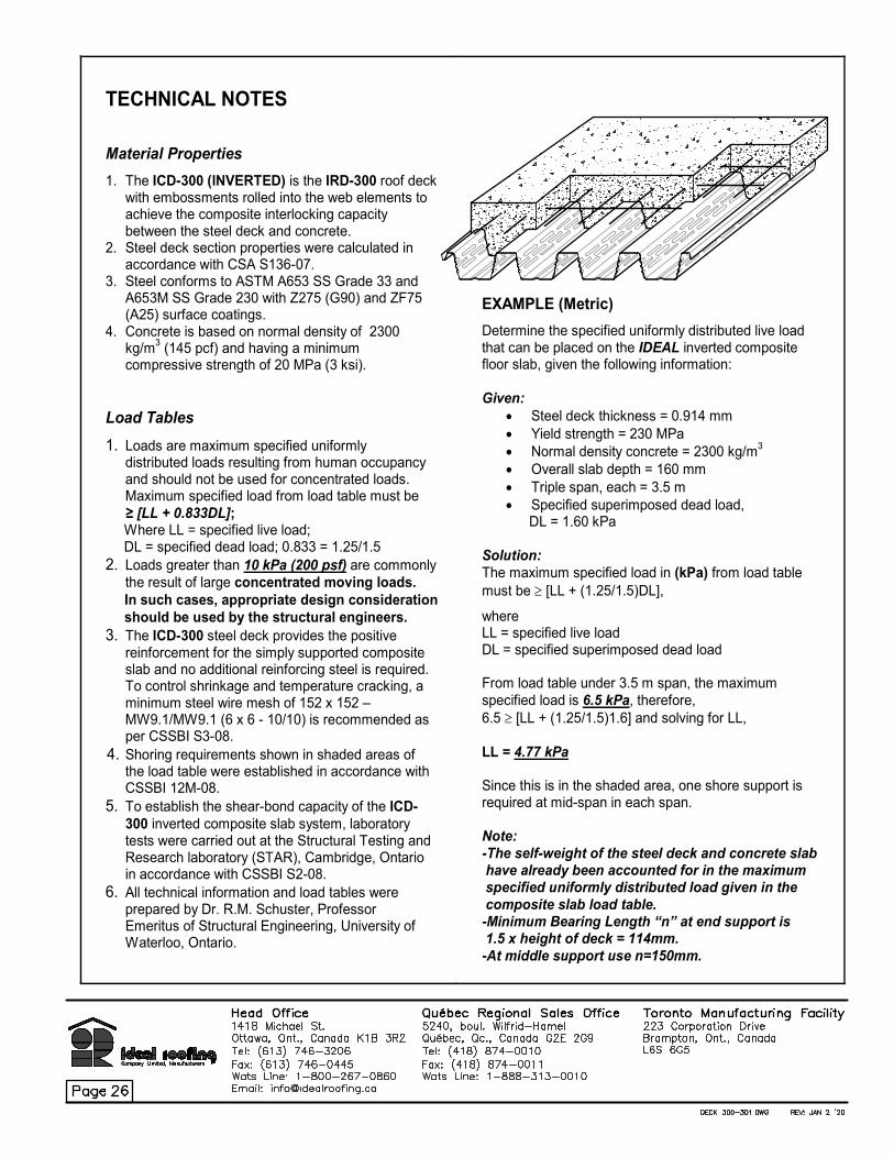
TECHNICAL NOTES
Material Properties
1. The ICD-300 (INVERTED) is the IRD-300 roof deck with embossments rolled into the web elements to achieve the composite interlocking capacity between the steel deck and concrete.
2. Steel deck section properties were calculated in accordance with CSA S136-07.
3. Steel conforms to ASTM A653 SS Grade 33 and A653M SS Grade 230 with Z275 (G90) and ZF75 (A25) surface coatings.
4. Concrete is based on normal density of 2300 kg/m
3 (145 pcf) and having a minimum
compressive strength of 20 MPa (3 ksi).
Load Tables
1. Loads are maximum specified uniformly distributed loads resulting from human occupancy and should not be used for concentrated loads. Maximum specified load from load table must be
≥ [LL + 0.833DL]; Where LL = specified live load; DL = specified dead load; 0.833 = 1.25/1.5
2. Loads greater than 10 kPa (200 psf) are commonly
the result of large concentrated moving loads.
In such cases, appropriate design consideration
should be used by the structural engineers.
3. The ICD-300 steel deck provides the positive reinforcement for the simply supported composite slab and no additional reinforcing steel is required. To control shrinkage and temperature cracking, a minimum steel wire mesh of 152 x 152 – MW9.1/MW9.1 (6 x 6 - 10/10) is recommended as per CSSBI S3-08.
4. Shoring requirements shown in shaded areas of the load table were established in accordance with CSSBI 12M-08.
5. To establish the shear-bond capacity of the ICD-300 inverted composite slab system, laboratory tests were carried out at the Structural Testing and Research laboratory (STAR), Cambridge, Ontario in accordance with CSSBI S2-08.
6. All technical information and load tables were prepared by Dr. R.M. Schuster, Professor Emeritus of Structural Engineering, University of Waterloo, Ontario.
EXAMPLE (Metric)
Determine the specified uniformly distributed live load that can be placed on the IDEAL inverted composite floor slab, given the following information: Given:
• Steel deck thickness = 0.914 mm
• Yield strength = 230 MPa
• Normal density concrete = 2300 kg/m3
• Overall slab depth = 160 mm
• Triple span, each = 3.5 m
• Specified superimposed dead load, DL = 1.60 kPa
Solution:
The maximum specified load in (kPa) from load table
must be ≥ [LL + (1.25/1.5)DL],
where LL = specified live load DL = specified superimposed dead load From load table under 3.5 m span, the maximum
specified load is 6.5 kPa, therefore,
6.5 ≥ [LL + (1.25/1.5)1.6] and solving for LL,
LL = 4.77 kPa Since this is in the shaded area, one shore support is required at mid-span in each span. Note:
-The self-weight of the steel deck and concrete slab have already been accounted for in the maximum specified uniformly distributed load given in the
composite slab load table. -Minimum Bearing Length “n” at end support is 1.5 x height of deck = 114mm.
-At middle support use n=150mm.

Acoustic roof deck is designed to serve as a sound-absorbing ceiling or an interior wall cladding
(e.g. school gymnasium, training facilities, airports and others) while maintaining most of its structural properties.
Using the IRD-150 and IRD-151 load table, the designer is urged to reduce the vertical load resistance by 5%.
The webs of the roof deck are perforated with 1/8” (3mm) diameter holes staggered 3/8” (9.53mm) on center.
The sound reduction is achieved by fibreglass strips placed between the perforated webs. These strips can be
supplied by Ideal Roofing and are available as a special order.
IRD-150 and IRD-151 Acoustic Deck is available in 22 gauge (0.030”/0.762mm), 20 gauge (0.036”/0.914mm)
and 18 gauge (0.048”/1.219mm) in galvanized G90 (Z275), galvanized G60 (Z180), galvanneal (satin coat) A25
(ZF075) and pre-painted.

Acoustic roof deck is designed to serve as a sound-absorbing ceiling or an interior wall cladding
(e.g. school gymnasium, training facilities, airports and others) while maintaining most of its structural properties.
Using the IRD-300 and IRD-301 load table, the designer is urged to reduce the vertical load resistance by 10%.
The webs of the roof deck are perforated with 1/8” (3mm) diameter holes staggered 3/8” (9.53mm) on center.
The sound reduction is achieved by fibreglass strips placed between the perforated webs. These strips can be
supplied by Ideal Roofing and are available as a special order.
IRD-300 and IRD-301 Acoustic Deck is available in 22 gauge (0.030”/0.762mm), 20 gauge (0.036”/0.914mm)
and 18 gauge (0.048”/1.219mm) in galvanized G90 (Z275), galvanized G60 (Z180), galvanneal (satin coat) A25
(ZF075) and pre-painted.