IR Full Line Catalog
254
Electronic Access Control Catalog for Open Architecture Solutions January 2013 Edition
-
Upload
horner-millwork -
Category
Documents
-
view
289 -
download
5
description
IR Full Line Catalog
Transcript of IR Full Line Catalog
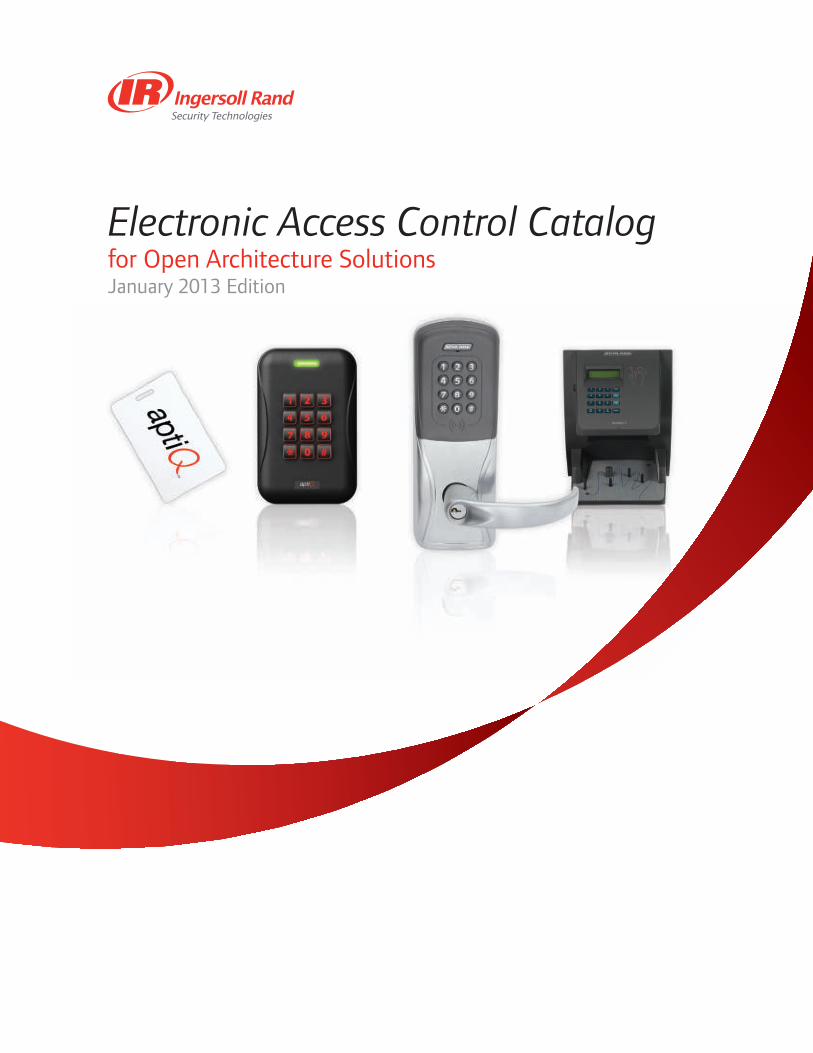
Electronic Access Control Catalogfor Open Architecture SolutionsJanuary 2013 Edition

Thank you for choosing Ingersoll Rand Security Technologies electronic access control products. This catalog contains overviews and technical specifications. In the back of the catalog you will find several wiring and riser diagrams for a number of products. The electronic security industry is ever-changing. In order to make sure that you have the most current and up to date product information, we recommend that you register your catalog by clicking on the registration button in the toolbar seen on the left side of your viewer. By registering and providing your email address, you will receive important updates to your catalog, and other product and solution information from Ingersoll Rand.
Quick Links
Ingersoll Rand Security Technologies Websitesecuritytechnologies.ingersollrand.com
YouTube Channel http://www.youtube.com/IngersollRandST
Facebook Pagefacebook.com/IngersollRandST
Bloghttp://blog.securitytechnologies.com
Twitterhttp://twitter.com/IngersollRandST
Contact Information
Customer Care & Sales Support: 877-671-7011
Technical Supportwww.schlage.com/support

Electronic Access Control CatalogOpen Architecture Products and Solutions
Table of Contents
Networked Locking Solutions005022 Networked Locking Solutions Introduction
Networked Locks
004446 AD-400 Networked Wireless Electronic Lock
004870 AD-401 Wireless Electronic Integrated Lock with FIPS 201 Compliant Multi-Tech + Keypad Reader
004448 AD-300 Networked Hardwired Electronic Lock
004869 AD-301 Hardwired Electronic Integrated Lock with FIPS 201 Compliant Multi-Tech + Keypad Reader
004382 AD-Series Exit Trim Compatibility
Networked Accessories
004447 PIM400-485 Panel Interface Module For RS485 Communication
004441 PIM400-TD2 Panel Interface Module Wiegand or Clock & Data Communication
004094 TK400 AD-Series Wireless Test Kit
004096 WPR400 AD-Series Wireless Portable Reader
004014 WRI400 Wireless Reader Interface
004013 GCK400 & ECK400 Wireless Gate Control Kits and Elevator Control Kits
004095 ANT400-REM Remote Antennas for Wireless System
004097 RLBD AD-Series Dry Contact Relay Board
004015 REPTR400 Wireless Repeater Kit
004443 Schlage Utility Software (SUS) on the Handheld Device (HHD)
Standalone Locking Solutions005427 Standalone Locking Solutions Introduction
Standalone Locks and Devices
004442 AD-200 Standalone Electronic Lock
004436 AD-250 Standalone Electronic Lock
004382 AD-Series Exit Trim Compatibility
004186 CO-100 Standalone Electronic Lock
004185 CO-200 Standalone Electronic Lock
004184 CO-250 Standalone Electronic Lock
004183 CO-Series Exit Trim Compatibility
004016 CT5000 Offline Controller
Standalone Accessories
004443 Schlage Utility Software (SUS) on the Handheld Device (HHD)
003940 Schlage Express Software
Electromechanical Locks005024 Electromechanical Locks Introduction
004998 L-Series Mortise Electrified Lock
004999 ND-Series Cylindrical Electrified Lock
Readers005025 Readers Introduction
005354 Multi-Technology Readers
009209 Multi-Technology Magnetic Stripe Readers
004256 FIPS 201-1 Compliant Readers
004250 SERIII-W Scramble Keypad
004246 SMR10 & SMR20 Mercury Magnetic Stripe Readers
004253 SMR5 Magnetic Stripe Reader
004252 SEKPDWG & SEKPDMGW Essex Electronic Keypads
005000 KP212 and KP232 Mullion Mounted Keypad
005132 CRM2 and CRP2 Enrollment Readers
Credentials005388 Credentials Introduction
005424 Smart Credentials
005425 Multi-Technology Credentials
005426 Proximity Credentials
Biometrics005027 Biometrics Introduction
HandKey® Biometric Hand Geometry Readers
004397 Biometric Access Control Products Quick Reference

004535 HandKey® II Biometric Hand Geometry Reader
004400 Biometric Terminal Accessories for HandKey®
004398 Enclosure Options for the HandKey® Series
004399 HandNet® for Windows
002872 Biometrics for Access Control Training Course Outline
System Components005028 System Components Introduction
Electric Strikes
005282 6100 Series Electric Strikes
005368 6200 Series Electric Strikes
003242 6300 Series Surface Mount Electric Strikes
009011 ES-6400 Series Modular Strike
ES-5990 5100 Series Electric Strikes
Electromagnetic Locks
M400 Series
004204 M490/492 Electromagnetic Locks
004205 M450/452 Electromagnetic Locks
004206 M420/422 Electromagnetic Locks
ES-6012 M490G Electromagnetic Gate Lock
004762 M490DE Delayed Egress Electromagnetic Lock
Specialty
004160 GF3000 Mortise Mounted Shear Lock
004159 GF3000 Surface Mounted Shear Lock
ES-6013 320M Mortise Mount MiniLine™ Electromagnetic Lock
004156 40/70 Series Electromagnetic Locks
009007 M390RFK Electromagnetic Locks
Power Supplies
PS900 Series Power Supplies
004193 PS906 6 amp Power Supply
004194 PS904 4 amp Power Supply
004195 PS902 2 amp Power Supply
004101 PS914 4 amp Power Supply (Von Duprin)
System Component Accessories
Pushbuttons
003910 620/631 Series Heavy Duty Pushbuttons
003911 700 Series Pushbuttons
ES-5977 740 Series Emergency Break Glass Release
003912 660 Series Mini Station Control
Keyswitches
ES-5978 650 Series Keyswitches
Request to Exit Bars
003909 672 Series TouchBar
003904 692 Series SmartBar™
Monitoring Stations and Consoles
ES-5988 800 Series Remote and Local Monitoring Stations
ES-5983 8200 Series Consoles
Other
ES-5984 Scan II™ Passive Infrared Motion Sensors
ES-5985 Electronic Horns
ES-5986 Door Position Switches
005006 Armored Door Cords with Caps
005011 PB405 and PB405S Electrified Deadbolts
Appendix005138 Appendix Introduction
Resource Guides
004085 AD-Series Resource Guide
004084 CO-Series Resource Guide
Solution Sheets
000076 Open Architecture Solution
Wiring Diagrams
104967 2 Door PS902-4RL-SI 2xM400Plus Maglocks 2xCard Reader - Rev B
104968 2 Single Doors 7982 Controller 2x4840 4xPushbut-tons - Rev B
105234 Pair PS914-2RS 2xEL-RX99 XF1500 2xDPS - Rev A
104970 Pair PS914-2RS EL 4640 2xPB Keyswitch x Remote PB
104972 Single 4600AO 6000FSE Electric Strike 2xPB - Rev B
104973 Single PS914-FA CX99 EPT10 DPS - Access Control Option - Rev B
104984 Single PS904 PS914 2xEL99 HKII Remote Release Computer
105348 Single AD-300 PIB300-2D ACP by others Weigand - Rev A
105349 Single AD-300 IR Integrated Partner ACP RS485 - Rev A
105350 Single AD-400 PIM400-TD2 ACP by others Wiegand - Rev A
105351 Single AD-400 PIM400-485 IR Integrated Partner ACP RS485 - Rev A
877-671-7011 • securitytechnologies.ingersollrand.com ©2013 Ingersoll Rand 005391 01/13
Net
wor
ked
Lock
ing
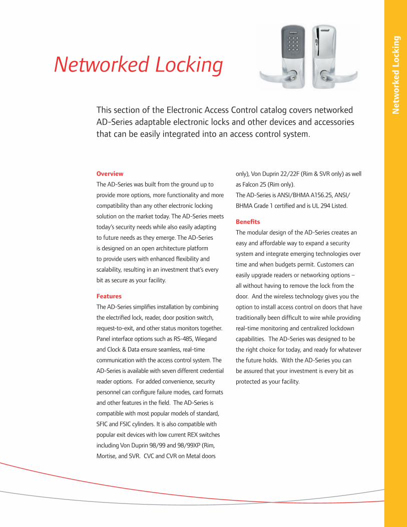
Networked Locking
This section of the Electronic Access Control catalog covers networked AD-Series adaptable electronic locks and other devices and accessories that can be easily integrated into an access control system.
Overview
The AD-Series was built from the ground up to
provide more options, more functionality and more
compatibility than any other electronic locking
solution on the market today. The AD-Series meets
today’s security needs while also easily adapting
to future needs as they emerge. The AD-Series
is designed on an open architecture platform
to provide users with enhanced flexibility and
scalability, resulting in an investment that’s every
bit as secure as your facility.
Features
The AD-Series simplifies installation by combining
the electrified lock, reader, door position switch,
request-to-exit, and other status monitors together.
Panel interface options such as RS-485, Wiegand
and Clock & Data ensure seamless, real-time
communication with the access control system. The
AD-Series is available with seven different credential
reader options. For added convenience, security
personnel can configure failure modes, card formats
and other features in the field. The AD-Series is
compatible with most popular models of standard,
SFIC and FSIC cylinders. It is also compatible with
popular exit devices with low current REX switches
including Von Duprin 98/99 and 98/99XP (Rim,
Mortise, and SVR. CVC and CVR on Metal doors
only), Von Duprin 22/22F (Rim & SVR only) as well
as Falcon 25 (Rim only).
The AD-Series is ANSI/BHMA A156.25, ANSI/
BHMA Grade 1 certified and is UL 294 Listed.
Benefits
The modular design of the AD-Series creates an
easy and affordable way to expand a security
system and integrate emerging technologies over
time and when budgets permit. Customers can
easily upgrade readers or networking options –
all without having to remove the lock from the
door. And the wireless technology gives you the
option to install access control on doors that have
traditionally been difficult to wire while providing
real-time monitoring and centralized lockdown
capabilities. The AD-Series was designed to be
the right choice for today, and ready for whatever
the future holds. With the AD-Series you can
be assured that your investment is every bit as
protected as your facility.
Macintosh HD:Users:trighter:Documents:_IngersollRand:EAC_Catalog:005022_EAC_Catalog_Networked_Intro:005022_Networked_Intro:005022_Networked_Intro_120512.indd December 7, 2012 3:29 PM Page 5
Net
wor
ked
Lock
ing
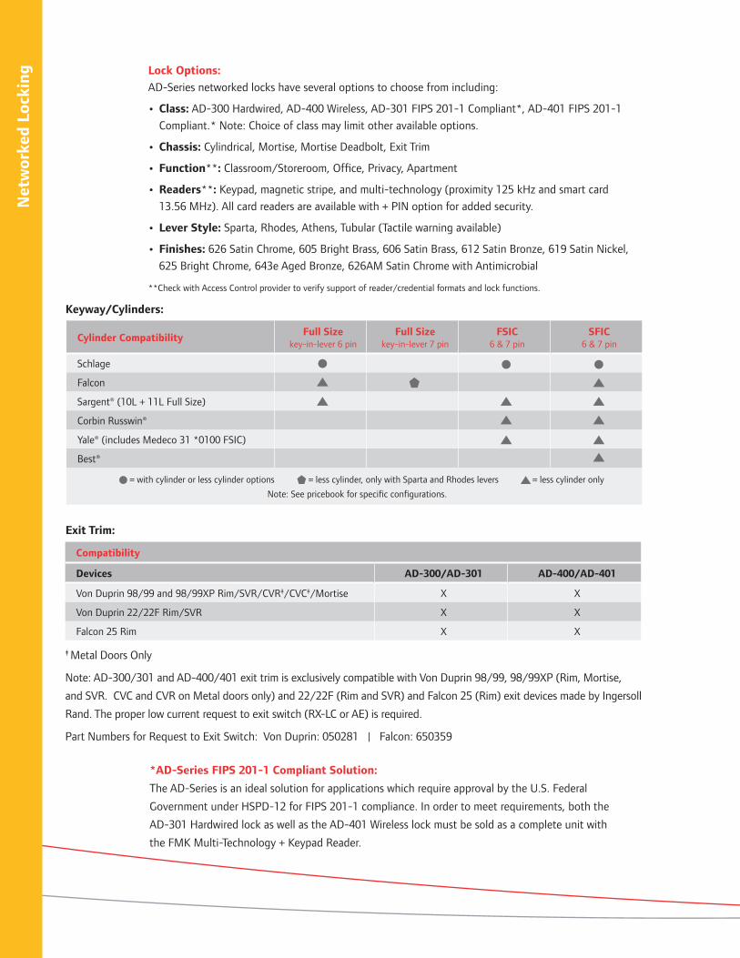
Cylinder Compatibility Full Size key-in-lever 6 pin
Full Size key-in-lever 7 pin
FSIC 6 & 7 pin
SFIC 6 & 7 pin
Schlage
Falcon
Sargent® (10L + 11L Full Size)
Corbin Russwin®
Yale® (includes Medeco 31 *0100 FSIC)
Best®
= with cylinder or less cylinder options = less cylinder, only with Sparta and Rhodes levers = less cylinder only
Note: See pricebook for specific configurations.
Compatibility
Devices AD-300/AD-301 AD-400/AD-401
Von Duprin 98/99 and 98/99XP Rim/SVR/CVR‡/CVC‡/Mortise X X
Von Duprin 22/22F Rim/SVR X X
Falcon 25 Rim X X
‡ Metal Doors Only
Note: AD-300/301 and AD-400/401 exit trim is exclusively compatible with Von Duprin 98/99, 98/99XP (Rim, Mortise,
and SVR. CVC and CVR on Metal doors only) and 22/22F (Rim and SVR) and Falcon 25 (Rim) exit devices made by Ingersoll
Rand. The proper low current request to exit switch (RX-LC or AE) is required.
Part Numbers for Request to Exit Switch: Von Duprin: 050281 | Falcon: 650359
*AD-Series FIPS 201-1 Compliant Solution:
The AD-Series is an ideal solution for applications which require approval by the U.S. Federal
Government under HSPD-12 for FIPS 201-1 compliance. In order to meet requirements, both the
AD-301 Hardwired lock as well as the AD-401 Wireless lock must be sold as a complete unit with
the FMK Multi-Technology + Keypad Reader.
Keyway/Cylinders:
Exit Trim:
Lock Options:
AD-Series networked locks have several options to choose from including:
• Class: AD-300 Hardwired, AD-400 Wireless, AD-301 FIPS 201-1 Compliant*, AD-401 FIPS 201-1
Compliant.* Note: Choice of class may limit other available options.
• Chassis: Cylindrical, Mortise, Mortise Deadbolt, Exit Trim
• Function**: Classroom/Storeroom, Office, Privacy, Apartment
• Readers**: Keypad, magnetic stripe, and multi-technology (proximity 125 kHz and smart card
13.56 MHz). All card readers are available with + PIN option for added security.
• Lever Style: Sparta, Rhodes, Athens, Tubular (Tactile warning available)
• Finishes: 626 Satin Chrome, 605 Bright Brass, 606 Satin Brass, 612 Satin Bronze, 619 Satin Nickel,
625 Bright Chrome, 643e Aged Bronze, 626AM Satin Chrome with Antimicrobial
**Check with Access Control provider to verify support of reader/credential formats and lock functions.
Macintosh HD:Users:trighter:Documents:_IngersollRand:EAC_Catalog:005022_EAC_Catalog_Networked_Intro:005022_Networked_Intro:005022_Networked_Intro_120512.indd December 7, 2012 3:29 PM Page 6 Macintosh HD:Users:trighter:Documents:_IngersollRand:EAC_Catalog:005022_EAC_Catalog_Networked_Intro:005022_Networked_Intro:005022_Networked_Intro_120512.indd December 7, 2012 3:29 PM Page 7

Net
wor
ked
Lock
ing
The Schlage AD-Series Wireless System allows
users to extend the reach of access control to
areas where running wires is difficult, expensive
or virtually impossible. Installations on interior
doors, remote doors, historic buildings, 24/7
facilities, elevators and parking gates are now
made possible by eliminating the need to run wires
directly to the access point. Options are available
to accommodate Wiegand, Clock & Data as well as
RS-485 connections to the access control system.
The AD-Series Wireless System communicates via
900 MHz frequency to a Panel Interface Module
(PIM) which is then hardwired back to the access
control panel. Each PIM can support up to 16
wireless devices within a 200' range in most
facilities and up to 1000' with clear line of site.
The 900 MHz band enables longer transmission
ranges; wavelengths travel a greater distance and
better penetrate typical building construction –
allowing for simplified system design. And since
900 MHz operates on a different frequency versus
WiFi, it won’t burden existing IT infrastructure.
Secure and reliable wireless communication
(heartbeat) from the PIM to the Access Control
System occurs on a periodic basis and is field
configurable; the factory default is set at 10
minutes. The AD-Series Wireless System utilizes
patent-pending Wake-Up On Radio™ technology
to deliver real-time activation at a remote
wireless lock while maintaining up to a 2 year
battery life. This feature, which is configurable
from 10 seconds to as fast as 1 second, enables
centralized emergency lockdown and unlock
commands in applications where both speed and
battery life are critical.
In addition to the AD-Series Locks, a variety of
wireless devices are available to extend the reach
of access control to applications which may be
difficult to wire. These include wireless remote
antennas (ANT400), wireless portable readers
(WPR400), wireless reader interfaces (WRI400),
wireless repeaters (REPTR400), wireless gate
control kits (GCK400) and wireless elevator
control kits (ECK400).
Extend the reach of access control with proven 900 MHz wireless technology
Macintosh HD:Users:trighter:Documents:_IngersollRand:EAC_Catalog:005022_EAC_Catalog_Networked_Intro:005022_Networked_Intro:005022_Networked_Intro_120512.indd December 7, 2012 3:29 PM Page 6 Macintosh HD:Users:trighter:Documents:_IngersollRand:EAC_Catalog:005022_EAC_Catalog_Networked_Intro:005022_Networked_Intro:005022_Networked_Intro_120512.indd December 7, 2012 3:29 PM Page 7
Net
wor
ked
Lock
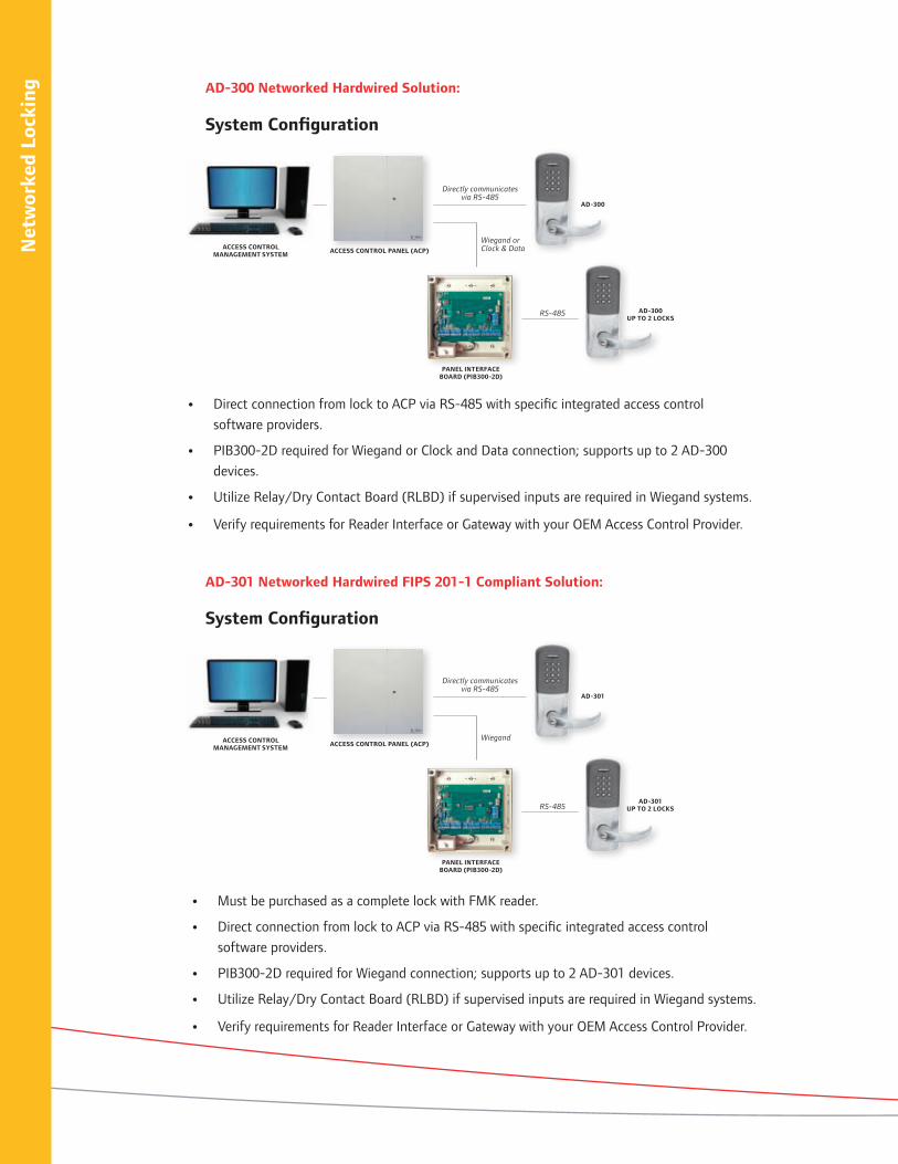
ing AD-300 Networked Hardwired Solution:
AD-301 Networked Hardwired FIPS 201-1 Compliant Solution:
System Configuration
System Configuration
ACCESS CONTROL PANEL (ACP)
Directly communicates via RS-485
RS-485
AD-300
Wiegand or Clock & Data
PANEL INTERFACEBOARD (PIB300-2D)
AD-300UP TO 2 LOCKS
ACCESS CONTROL MANAGEMENT SYSTEM
ACCESS CONTROL PANEL (ACP)
RS-485
Wiegand
PANEL INTERFACEBOARD (PIB300-2D)
AD-301UP TO 2 LOCKS
ACCESS CONTROL MANAGEMENT SYSTEM
• Direct connection from lock to ACP via RS-485 with specific integrated access control
software providers.
• PIB300-2D required for Wiegand or Clock and Data connection; supports up to 2 AD-300
devices.
• Utilize Relay/Dry Contact Board (RLBD) if supervised inputs are required in Wiegand systems.
• Verify requirements for Reader Interface or Gateway with your OEM Access Control Provider.
• Must be purchased as a complete lock with FMK reader.
• Direct connection from lock to ACP via RS-485 with specific integrated access control
software providers.
• PIB300-2D required for Wiegand connection; supports up to 2 AD-301 devices.
• Utilize Relay/Dry Contact Board (RLBD) if supervised inputs are required in Wiegand systems.
• Verify requirements for Reader Interface or Gateway with your OEM Access Control Provider.
Directly communicates via RS-485
AD-301
Macintosh HD:Users:trighter:Documents:_IngersollRand:EAC_Catalog:005022_EAC_Catalog_Networked_Intro:005022_Networked_Intro:005022_Networked_Intro_120512.indd December 7, 2012 3:29 PM Page 8 Macintosh HD:Users:trighter:Documents:_IngersollRand:EAC_Catalog:005022_EAC_Catalog_Networked_Intro:005022_Networked_Intro:005022_Networked_Intro_120512.indd December 7, 2012 3:29 PM Page 9

Net
wor
ked
Lock
ing
* If enabled, grants access to last 113 unique user ID’s, option to expand to 1,000. Or, use facility/site codes instead of user ID’s. No events are captured in audit trail when operating in cache mode.
† 75 bit output format default. Configurable to other output formats. Check with access control provider for specific support.
HardwiredHardwired
FIPS 201-1 CompliantHardwired
Hardwired FIPS 201-1 Compliant
AD-300 AD-301 AD-300 AD-301
System Info - Consult with OEM Access Control System Provider for Specific Requirements
Communication to/from Controller Direct - RS-485 Wiegand or Clock & Data
Panel Interface Module N/A N/A PIB300-2D
Number of Locks Per Panel Interface Module
N/A N/A Up to 2
Relay/Dry Contact Board (RLBD) N/A N/A Yes, if supervised inputs are required
Reader Interface/Gateway As required by OEM Access Control System
Device Capacity
Number of UsersAs supported by OEM Access Control System
Number of Audits
Degraded Cache Mode in Lock** Yes**
Reader Options - Consult with OEM Access Control System Provider for Credential Format Compatibility
Keypad Only Yes, as supported by OEM Access Control System
No Yes, as supported by OEM Access Control System
No
Magnetic Stripe Card No No
FIPS 201-1 Multi-Technology - 125 kHz and 13.56 MHz
No Yes No Yes
Multi-Technology - 125 kHz and 13.56 MHz Yes, as supported by
OEM Access Control System
No Yes, as supported by OEM Access Control
System
No
PIV & PIV-I Compatible† Yes Yes
Card + PIN Yes Yes
Status Monitors - Consult with OEM Access Control System Provider for Specific Support
Request to Exit
Yes, as supported by OEM Access Control SystemDoor Position Switch
Interior Tamper Guard
Lock/Unlock Status Clutch PositionYes, as supported by OEM Access Control System No
Mechanical Key Override (ATK)
Request to Enter Yes, as supported by OEM Access Control System
Battery StatusN/A
Battery Voltage Level
Communication Status
YesRemote Lockdown (from Host)
Remote Unlock (from Host)
Deadbolt PositionYes, as supported by OEM Access Control System No
Interior Push Button
Chassis Options - Consult with OEM Access Control System Provider for Specific Support
CylindricalYes
Mortise
Mortise Deadbolt Yes, as supported by OEM Access Control System No
Exit Trim Yes - See Exit Trim Compatibility Data Sheet for specifics
Functions - Consult with OEM Access Control System Provider for Specific Support
Classroom/Storeroom (70) Yes - Classroom/Storeroom is not available with Mortise Deadbolt Chassis
Privacy (40) Yes - Classroom/Storeroom is not available with Mortise Deadbolt Chassis. Privacy, Office and Apart-
ment as supported by OEM Access Control SystemNoOffice (50)
Apartment (60)
Accessories - Consult with OEM Access Control System Provider for Specific Support
HHD - Handheld Programming Device
Yes
Macintosh HD:Users:trighter:Documents:_IngersollRand:EAC_Catalog:005022_EAC_Catalog_Networked_Intro:005022_Networked_Intro:005022_Networked_Intro_120512.indd December 7, 2012 3:29 PM Page 8 Macintosh HD:Users:trighter:Documents:_IngersollRand:EAC_Catalog:005022_EAC_Catalog_Networked_Intro:005022_Networked_Intro:005022_Networked_Intro_120512.indd December 7, 2012 3:29 PM Page 9

Net
wor
ked
Lock
ing AD-400 Networked Wireless Solution:
AD-401 Networked Wireless FIPS201-1 Compliant Solution:
ACCESS CONTROL MANAGEMENT SYSTEM
ACCESS CONTROL PANEL (ACP)
System Configuration
System Configuration
• PIM400-TD2 required for Wiegand or Clock and Data connections; supports up
to 2 AD Series devices.
• PIM400-485, if supported by OEM provider, supports up to 16 AD-400 devices.
• Utilize Relay/Dry Contact Board (RLBD) if supervised inputs are required in
Wiegand systems.
• Verify requirements for Reader Interface or Gateway with your OEM Access
Control Provider.
• Must be purchased as a complete lock with FMK reader.
• PIM400-485 required for RS-485 connection with integrated access control software
providers; supports up to 16 AD-401 devices.
• PIM400-TD2 required for Wiegand connection; supports up to 2 AD-401 devices.
• Utilize Relay/Dry Contact Board (RLBD) if supervised inputs are required in Wiegand systems.
• Verify requirements for Reader Interface or Gateway with your OEM Access Control Provider.
RS-485AD-400
(UP TO 16 LOCKS)PANEL INTERFACE
MODULE (PIM400-485)
AD-400 (UP TO 2 LOCKS)
PANEL INTERFACE MODULE (PIM400-TD2)
Wiegand or Clock & Data
ACCESS CONTROL MANAGEMENT SYSTEM
ACCESS CONTROL PANEL (ACP)
RS-485AD-401
(UP TO 16 LOCKS)PANEL INTERFACE
MODULE (PIM400-485)
AD-401 (UP TO 2 LOCKS)
PANEL INTERFACE MODULE (PIM400-TD2)
Wiegand
Macintosh HD:Users:trighter:Documents:_IngersollRand:EAC_Catalog:005022_EAC_Catalog_Networked_Intro:005022_Networked_Intro:005022_Networked_Intro_120512.indd December 7, 2012 3:29 PM Page 10 Macintosh HD:Users:trighter:Documents:_IngersollRand:EAC_Catalog:005022_EAC_Catalog_Networked_Intro:005022_Networked_Intro:005022_Networked_Intro_120512.indd December 7, 2012 3:29 PM Page 11

Net
wor
ked
Lock
ing
*PIM400-485 sold exclusively through OEM providers.** If enabled, grants access to last 113 unique user ID’s, option to expand to 1,000. Or, use facility/site codes instead of user ID’s. No events are captured in
audit trail when operating in cache mode.†75 bit output format default. Configurable to other output formats. Check with access control provider for specific support.
HardwiredHardwired
FIPS 201-1 CompliantHardwired
Hardwired FIPS 201-1 Compliant
AD-400 AD-401 AD-400 AD-401
System Info - Consult with OEM Access Control System Provider for Specific Requirements
Communication to/from Controller Direct - RS-485 Wiegand or Clock & Data
Panel Interface Module PIM400-485* PIM400-TD2
Number of Locks Per Panel Interface Module
Up to 16 Up to 2
Relay/Dry Contact Board (RLBD) No Yes, if supervised inputs are required
Reader Interface/Gateway As required by OEM Access Control System
Device Capacity
Number of UsersAs supported by OEM Access Control System
Number of Audits
Degraded Cache Mode in Lock** Yes**
Reader Options - Consult with OEM Access Control System Provider for Credential Format Compatibility
Keypad Only Yes, as supported by OEM Access Control System
No Yes, as supported by OEM Access Control System
No
Magnetic Stripe Card No No
FIPS 201-1 Multi-Technology - 125 kHz and 13.56 MHz
No Yes No Yes
Multi-Technology - 125 kHz and 13.56 MHz Yes, as supported by
OEM Access Control System
No Yes, as supported by OEM Access Control
System
No
PIV & PIV-I Compatible† Yes Yes
Card + PIN Yes Yes
Status Monitors - Consult with OEM Access Control System Provider for Specific Support
Request to Exit
Yes, as supported by OEM Access Control SystemDoor Position Switch
Interior Tamper Guard
Lock/Unlock Status Clutch PositionYes, as supported by OEM Access Control System No
Mechanical Key Override (ATK)
Request to EnterYes, as supported by OEM Access Control System
Battery Status
Battery Voltage Level Yes, as supported by OEM Access Control System No
Communication Status Yes
Remote Lockdown (from Host)
Yes, as supported by OEM Access Control System
Yes, requires configuration at PIM via HHDRemote Unlock (from Host)
Deadbolt PositionNo
Interior Push Button
Chassis Options - Consult with OEM Access Control System Provider for Specific Support
CylindricalYes
Mortise
Mortise Deadbolt Yes, as supported by OEM Access Control System No
Exit Trim Yes - See Exit Trim Compatibility Data Sheet for specifics
Functions - Consult with OEM Access Control System Provider for Specific Support
Classroom/Storeroom (70) Yes - Classroom/Storeroom is not available with Mortise Deadbolt Chassis
Privacy (40) Yes - Classroom/Storeroom is not available with Mortise Deadbolt Chassis. Privacy, Office and Apart-
ment as supported by OEM Access Control SystemNoOffice (50)
Apartment (60)
Accessories - Consult with OEM Access Control System Provider for Specific Support
HHD - Handheld Programming Device
Yes, as supported by OEM Access Control System
Wireles Portable Reader (WPR400/401)
Wireless Reader Interface (WRI400)
Wireless Repeater (REPTR400)
Wireless Antenna (ANT400)
Wireless Signal Test Kit (TK400)
Wireless Gate Kit (GCK400)
Wireless Elevator Kit (ECK400)
Macintosh HD:Users:trighter:Documents:_IngersollRand:EAC_Catalog:005022_EAC_Catalog_Networked_Intro:005022_Networked_Intro:005022_Networked_Intro_120512.indd December 7, 2012 3:29 PM Page 10 Macintosh HD:Users:trighter:Documents:_IngersollRand:EAC_Catalog:005022_EAC_Catalog_Networked_Intro:005022_Networked_Intro:005022_Networked_Intro_120512.indd December 7, 2012 3:29 PM Page 11

877-671-7011 • securitytechnologies.ingersollrand.com ©2012 Ingersoll Rand 005022 11/12
THIS PAGE IS INTENTIONALLY BLANK.
Macintosh HD:Users:trighter:Documents:_IngersollRand:EAC_Catalog:005022_EAC_Catalog_Networked_Intro:005022_Networked_Intro:005022_Networked_Intro_120512.indd December 7, 2012 3:29 PM Page 12

OverviewAD-Series electronic locks from Schlage are designed to be modular and provide more options to choose from, more functionality in the lock and more compatibility with existing systems. Its patent-pending modular design allows the lock to be customized to fit the needs of an application now, and can change to meet future needs without removing it from the door.
Factory orderable options include choices of credential readers, chassis type, network configurations, locking functions, power options, lever styles and finishes. It also offers a wide selection of features that can be configured in the field to customize your openings.
To simplify installation, the AD-Series combines all the hardware components required at the door for a complete access control system into one integrated design that includes the electrified lock, credential reader, request-to-exit and -enter sensors, door position switch, tamper guard and more.
The AD-400 wireless networked lock gives you many of the key benefits of a hardwired access control system — without the wires. This allows you to secure doors that were traditionally difficult to run wires to in the past—and increase the security throughout your facility.
The AD-400 has a number of features built in that are configurable in the field and a long list of items that can be monitored by access control software. Please consult your access control software partner for details on the integration of specific features.
AD-400 Networked Wireless Electronic Lock
Features and Benefits
• Open Architecture platform • Panel interface options ensure seamless communication
with your system• Non-invasive installations for historic buildings and
sensitive areas• Secure encrypted data transmission• Unique communication protocols that won’t interfere
with other wireless networks• Patent-pending wireless feature that enables efficient
centralized lockdown in less than 10 seconds while still optimizing battery life up to 2 years
• Available in cylindrical, mortise, mortise with deadbolt and exit trim
• Compatible with major brands of master key systems• Wireless accessories available for remote, gate, elevator
and portable (mustering) applications• AD-Series with multi-technology readers are NFC
compatible• ANSI/BHMA A156.25, ANSI/BHMA Grade 1,
UL 294, UL10C, FCC Part 15, ADA, RoHS
Net
wor
ked
Lock
ing
Solu
tion
s
AD
-400
Wire
less
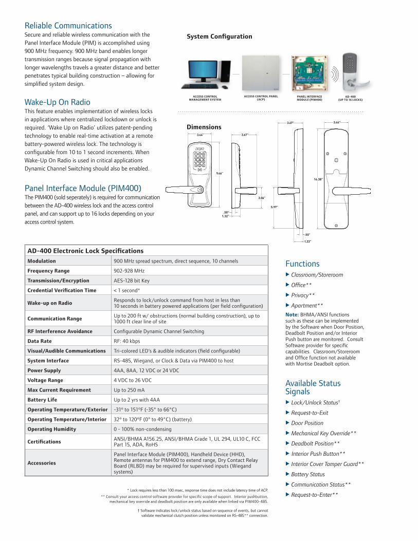
Reliable CommunicationsSecure and reliable wireless communication with the Panel Interface Module (PIM) is accomplished using 900 MHz frequency. 900 MHz band enables longer transmission ranges because signal propagation with longer wavelengths travels a greater distance and better penetrates typical building construction – allowing for simplified system design.
Wake-Up On RadioThis feature enables implementation of wireless locks in applications where centralized lockdown or unlock is required. ‘Wake Up on Radio’ utilizes patent-pending technology to enable real-time activation at a remote battery-powered wireless lock. The technology is configurable from 10 to 1 second increments. When Wake-Up On Radio is used in critical applications Dynamic Channel Switching should also be enabled.
Panel Interface Module (PIM400)The PIM400 (sold seperately) is required for communication between the AD-400 wireless lock and the access control panel, and can support up to 16 locks depending on your access control system.
Dimensions
Functions Classroom/Storeroom
Office**
Privacy**
Apartment**
Note: BHMA/ANSI functions such as these can be implemented by the Software when Door Position, Deadbolt Position and/or Interior Push button are monitored. Consult Software provider for specific capabilities. Classroom/Storeroom and Office function not available with Mortise Deadbolt option.
Available Status Signals Lock/Unlock Status†
Request-to-Exit
Door Position
Mechanical Key Override**
Deadbolt Position**
Interior Push Button**
Interior Cover Tamper Guard**
Battery Status
Communication Status**
Request-to-Enter**
ACCESS CONTROL MANAGEMENT SYSTEM
ACCESS CONTROL PANEL (ACP)
AD-400 (UP TO 16 LOCKS)
PANEL INTERFACE MODULE (PIM400)
System Configuration
* Lock requires less than 100 msec, response time does not include latency time of ACP.
** Consult your access control software provider for specific scope of support. Interior pushbutton, mechanical key override and deadbolt position are only available when linked via PIM400-485.
† Software indicates lock/unlock status based on sequence of events, but cannot validate mechanical clutch position unless monitored on RS-485** connection.
AD-400 Electronic Lock Specifications
Modulation 900 MHz spread spectrum, direct sequence, 10 channels
Frequency Range 902-928 MHz
Transmission/Encryption AES-128 bit Key
Credential Verification Time < 1 second*
Wake-up on Radio Responds to lock/unlock command from host in less than 10 seconds in battery powered applications (per field configuration)
Communication Range Up to 200 ft w/ obstructions (normal building construction), up to 1000 ft clear line of site
RF Interference Avoidance Configurable Dynamic Channel Switching
Data Rate RF: 40 kbps
Visual/Audible Communications Tri-colored LED’s & audible indicators (field configurable)
System Interface RS-485, Wiegand, or Clock & Data via PIM400 to host
Power Supply 4AA, 8AA, 12 VDC or 24 VDC
Voltage Range 4 VDC to 26 VDC
Max Current Requirement Up to 250 mA
Battery Life Up to 2 yrs with 4AA
Operating Temperature/Exterior -31º to 151ºF (-35° to 66°C)
Operating Temperature/Interior 32º to 120ºF (0° to 49°C) (battery)
Operating Humidity 0 - 100% non-condensing
Certifications ANSI/BHMA A156.25, ANSI/BHMA Grade 1, UL 294, UL10 C, FCC Part 15, ADA, RoHS
Accessories
Panel Interface Module (PIM400), Handheld Device (HHD), Remote antennas for PIM400 to extend range, Dry Contact Relay Board (RLBD) may be required for supervised inputs (Wiegand systems)

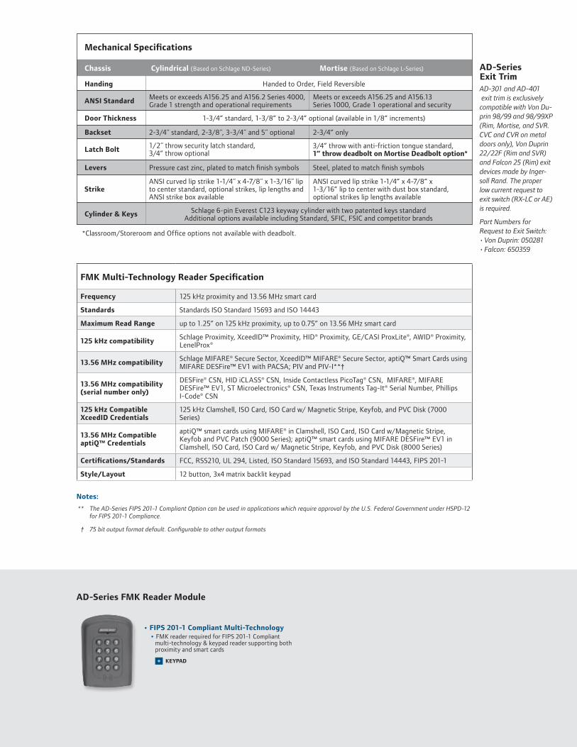
AD-Series Exit Trim
Available AD-Series Reader Modules
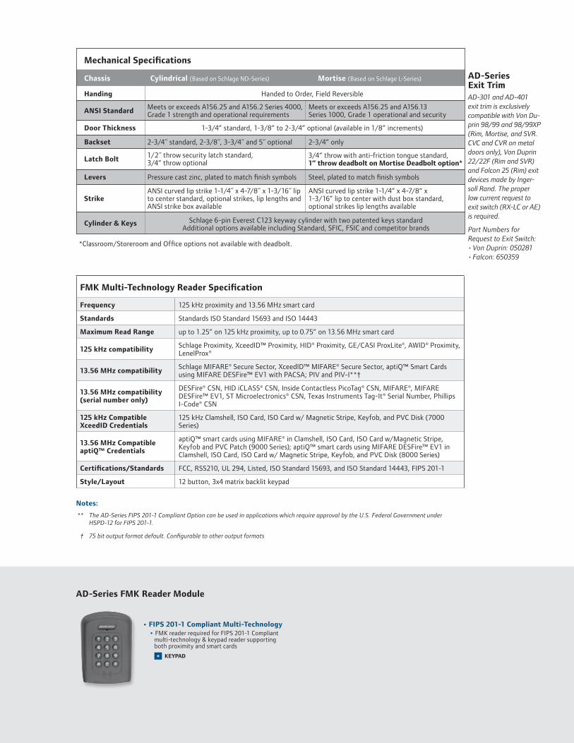
Mechanical Specifications
Handing
Chassis Cylindrical (Based on Schlage ND-Series)
Meets or exceeds A156.25 and A156.2 Series 4000, Grade 1 strength and operational requirements
2-3/4˝ standard, 2-3/8˝, 3-3/4˝ and 5˝ optional
1/2˝ throw security latch standard, 3/4” throw optional
Pressure cast zinc, plated to match finish symbols
ANSI curved lip strike 1-1/4˝ x 4-7/8˝ x 1-3/16˝ lip to center standard, optional strikes, lip lengths and ANSI strike box available
Mortise (Based on Schlage L-Series)
Meets or exceeds A156.25 and A156.13 Series 1000, Grade 1 operational and security
2-3/4” only
Steel, plated to match finish symbols
ANSI curved lip strike 1-1/4” x 4-7/8” x 1-3/16” lip to center with dust box standard, optional strikes lip lengths available
ANSI Standard
Door Thickness
Backset
Latch Bolt
Levers
Strike
Cylinder & Keys
Handed to Order, Field Reversible
1-3/4” standard, 1-3/8” to 2-3/4” optional (available in 1/8” increments)
Schlage 6-pin Everest C123 keyway cylinder with two patented keys standard Additional options available including Standard, SFIC, FSIC and competitor brands
3/4” throw with anti-friction tongue standard, 1” throw deadbolt on Mortise Deadbolt option*
• Magnetic Stripe (Swipe)
• Magnetic Stripe (Swipe)
KEYPAD+
*Classroom/Storeroom and Office options not available with deadbolt.
• Magnetic Stripe (Insertion)
• Keypad• Multi-Technology • Proximity • Smart Card
• Multi-Technology • Proximity • Smart Card
KEYPAD+
• Magnetic Stripe (Insertion)
KEYPAD+
Notes:
** FIPS 201-1 Compliant Option Available: The AD-Series can be used in applications which require approval by the U.S. Federal Government under HSPD-12 for FIPS 201-1 Compliance. Specific components are required, please see the AD-401 data sheet or AD-301 data sheet for complete details.
† 75 bit output format default. Configurable to other output formats
Benefits of AD-Series Multi-Technology Readers:• Reads multiple brand of both
proximity (125 kHz) and smart (13.56 MHz) technologies with single device
• AD-Series multi-technology readers are NFC compatible
• Allows end user to migrate to more secure credentials over time and as budgets permit
Additional Readers Magnetic Stripe• Now available with choice of Inser-
tion or Swipe style readers• Triple Track Reader (1, 2 or 3),
field configurable• ABA, ISO76XX Standard• Option for 12 button, 3x4 matrix
backlit keypad
Keypad• Backlit keypad • 12 button, 3x4 matrix
Multi-Technology Reader Specification
Frequency 125 kHz proximity and 13.56 MHz smart card
Standards Standards ISO Standard 15693 and ISO 14443
Maximum Read Range up to 1.25” on 125 kHz proximity, up to 0.75” on 13.56 MHz smart card
125 kHz compatibility Schlage Proximity, XceedID™ Proximity, HID® Proximity, GE/CASI ProxLite®, AWID® Proximity, LenelProx®
13.56 MHz compatibilitySchlage MIFARE® Secure Sector, XceedID™ MIFARE® Secure Sector, aptiQ™ Smart Cards using MIFARE DESFire™ EV1 with PACSA; PIV and PIV-I**†
13.56 MHz compatibility (serial number only)
DESFire® CSN, HID iCLASS® CSN, Inside Contactless PicoTag® CSN, MIFARE®, MIFARE DESFire™ EV1, ST Microelectronics® CSN, Texas Instruments Tag-It® Serial Number, Phillips I-Code® CSN
125 kHz Compatible XceedID Credentials
125 kHz Clamshell, ISO Card, ISO Card w/ Magnetic Stripe, Keyfob, and PVC Disk (7000 Series)
13.56 MHz Compatible aptiQ™ Credentials
aptiQ™ smart cards using MIFARE® in Clamshell, ISO Card, ISO Card w/Magnetic Stripe, Keyfob and PVC Patch (9000 Series); aptiQ™ smart cards using MIFARE DESFire™ EV1 in Clamshell, ISO Card, ISO Card w/ Magnetic Stripe, Keyfob, and PVC Disk (8000 Series)
Certifications/Standards FCC, RSS210, UL 294, Listed, ISO Standard 15693, and ISO Standard 14443
Style/Layout Option for 12 button, 3x4 matrix backlit keypad
AD-300 and AD-400 exit trim is exclusively compatible with Von Du-prin 98/99 and 98/99XP (Rim, Mortise, and SVR. CVC and CVR on Metal doors only), Von Duprin 22/22F (Rim and SVR) and Falcon 25 (Rim) exit devices made by Inger-soll Rand. The proper low current request to exit switch (RX-LC or AE) is required. Part Numbers for Request to Exit Switch:• Von Duprin: 050281• Falcon: 650359

877-671-7011 • securitytechnologies.ingersollrand.com
Selections Correspond With the Numbers Above
Lever styles
Sparta Rhodes
Athens Tubular
Warm tone finishes
Cool tone finishes
605 606 612 643eBright Brass Satin Brass Satin Bronze Aged Bronze
619 625 626 626AMSatin Nickel Bright Satin Chrome Satin Chrome Chrome with Antimicrobial
©2013 Ingersoll Rand 004446 01/13
Standard options are indicated in bold. See price book for specific configuration options.
Standard cylinders shown, SFIC and FSIC also available.
11 Battery4B 4AA8B 8AA
12 Backset & Latch or Armor FrontCylindrical13-049 2-3/4” Backset, Deadlatch,
Square Corner, 1-1/8” x 2-1/4” Mortise 09-663 Armor Front, 1-1/4” Wide,
Square CornerSee price book for mortise deadbolt and other backset and latch options or armor front options
13 Strike
Cylindrical 10-025 1-3/16 Lip, ANSI, No Box, 1-1/4” x 4-7/8” Mortise 10-072 1-3/16” Lip, 1-1/4” x 4-7/8” Square Corner, Box See price book for other available strikes
14 Door Thickness1-3/4”Other thicknesses available between 1-3/8” and 2-3/4”See price book for detail
6 LeverSPA SpartaRHO RhodesATH AthensTLR TubularAvailable with knurled surface
7 Finish626 Satin Chrome605 Bright Brass606 Satin Brass612 Satin Bronze619 Satin Nickel625 Bright Chrome643e Aged Bronze626AM Satin Chrome Antimicrobial
8 Lever Cylinder TypePD Schlage 6-pin Full CylinderSee price book for other SFIC, FSIC and Less Cores options available. Compatible with Schlage, Sargent, Corbin, Medeco and Yale
9 Keyway TypeC123 Everest See price book for other available keyway options including master keying
10 HandingRH Right Handed LH Left HandedField reversible
3 ChassisCY CylindricalMS MortiseMD Mortise Deadbolt993R Exit Trim – Rim/CVC/CVR993S Exit Trim – SVR993M Exit Trim – Mortise993DT Non-Functioning Dummy Trim for Exit
4 Function70 Classroom/Storeroom50 Office40 Privacy60 ApartmentLock function capabilities are determined by users access control system
5 ReaderKP KeypadMG Magnetic Stripe (Insertion)MGK Magnetic Stripe + Keypad
(Insertion)MS Magnetic Stripe (Swipe)MSK Magnetic Stripe + Keypad (Swipe)MT Multi-Technology (125 kHz and 13.56 MHz)MTK Multi-Technology + Keypad (125 kHz and 13.56 MHz)DT Dummy Trim
INGERSOLL RAND, the Ingersoll Rand logo, SCHLAGE, the SCHLAGE logo, XceedID, Von Duprin, Falcon and aptiQ are trademarks of Ingersoll-Rand plc, its subsidiaries and/or affiliates in the United States and other countries. Inside PicoTag is a trademark of Inside Technologies. GE, CASI and ProxLite are trademarks of General Electric Corporation. MIFARE and MIFARE DESFire EV1 are trademarks of NXP B.V. HID and iCLASS are trademarks of HID Corporation. Tag-It is a trademark of Texas Instruments. STMicroelectronics is a trademark of STMicroelectronics Inc. Infineon and my-d are trademarks of Infineon Technologies. AWID is a trademark of Applied Wireless Identifications Group. All other trademarks are the property of their respective owners.
AD-400-CY-70-MG - SPA-626-PD-C123 -RH - 4B-13-049-10-025-1-3/4Se
ries
Cla
ss
Ch
assi
s
Fun
ctio
n
Rea
der
Leve
r St
yle
Fin
ish
Leve
r C
ylin
der
Key
ing
Typ
e
Han
din
g
Bat
tery
Stri
ke
Doo
r T
hic
knes
s
Bac
kset
&
Lat
ch
3 41 2 5 6 7 8 9 10 11 12 13 14
Ordering InformationAvailable through one of our GSA Schedule 84 approved distributors; BAA options available

OverviewAD-Series electronic locks from Schlage are designed to be modular and provide more options to choose from, more functionality in the lock and more compatibility with existing systems. Its patent-pending modular design allows the lock to be customized to fit the needs of an application now, and can change to meet future needs without removing it from the door.
The AD-401 is an ideal solution for applications which require approval by the U.S. Federal Government under HSPD-12 for FIPS 201 Compliance. The AD-401 electronic integrated lock with FMK multi-technology reader + keypad is FIPS 201-1 compliant for use in U.S. Federal Agency Buildings using smart card technology. The AD-401 lock with an FMK reader allows both a Wiegand and RS-485 solution.
Factory orderable options include choices of chassis type, network configurations, locking functions, power options, lever styles and finishes. It also offers a selection of features that can be configured in the field to customize your openings.
To simplify installation, the AD-Series combines all the hardware components required at the door for a complete access control system into one integrated design that includes the electrified lock, credential reader, request-to-exit and -enter sensors, door position switch, tamper guard and more.
The AD-401 wireless networked lock gives you many of the key benefits of a hardwired access control system — without the wires. This allows you to secure doors that were traditionally difficult to run wires to in the past—and increase the security throughout your facility.
The AD-401 has a number of features built in that are configurable in the field and a long list of items that can be monitored by access control software. Please consult your access control software partner for details on the integration of specific features.
AD-401 FIPS 201-1 Compliant Networked Wireless Lock with Multi-Technology & Keypad Reader
Features and Benefits
• Open Architecture platform • Panel interface options ensure seamless communication
with your system: - AD-401 with integrated RS-485 software providers
will require the use of a PIM400-485 Panel Interface Module which can support up to 16 AD-401 devices
- AD-401 in Wiegand systems will require the use of a PIM400-TD2 Panel Interface Module which can support up to 2 AD-401 devices and may require the optional dry-contact relay board (RLBD)
• Non-invasive installations for historic buildings and sensitive areas
• Secure encrypted data transmission• Unique communication protocols that won’t interfere
with other wireless networks• Patent-pending wireless feature that enables efficient
centralized lockdown in less than 10 seconds while still optimizing battery life up to 2 years
• Available in cylindrical, mortise, mortise with deadbolt and exit trim
• Compatible with major brands of master key systems• Wireless accessories available for remote, gate,
elevator and portable (mustering) applications• ANSI/BHMA A156.25, ANSI/BHMA Grade 1,
UL 294, UL10C, FCC Part 15, ADA, RoHS, FIPS 201-1
Net
wor
ked
Lock
ing
Solu
tion
s
AD
-401
FIP
S 20
1-1
Com
plia
nt W
irele
ss

Reliable CommunicationsSecure and reliable wireless communication with the Panel Interface Module (PIM) is accomplished using 900 MHz frequency. 900 MHz band enables longer transmission ranges because signal propagation with longer wavelengths travels a greater distance and better penetrates typical building construction – allowing for simplified system design.
Wake-Up On RadioThis feature enables implementation of wireless locks in applications where centralized lockdown or unlock is required. ‘Wake Up on Radio’ utilizes patent-pending technology to enable real-time activation at a remote battery-powered wireless lock. The technology is configurable from 10 to 1 second increments. When Wake-Up On Radio is used in critical applications Dynamic Channel Switching should also be enabled.
Panel Interface Module (PIM400)The PIM400 (sold seperately) is required for communication between the AD-401 wireless lock and the access control panel, and can support up to 16 locks depending on your access control system.
Dimensions
Functions Classroom/Storeroom
Office**
Privacy**
Apartment**
Note: BHMA/ANSI functions such as these can be implemented by the Software when Door Position, Deadbolt Position and/or Interior Push button are monitored. Consult Software provider for specific capabilities. Classroom/Storeroom and Office function not available with Mortise Deadbolt option.
Available Status Signals Lock/Unlock Status†
Request-to-Exit
Door Position
Mechanical Key Override**
Deadbolt Position**
Interior Push Button*
Interior Cover Tamper Guard*
Battery Status
Communication Status*
Request-to-Enter*
System Configuration
* Lock requires less than 100 msec, response time does not include latency time of ACP.
** Consult your access control software provider for specific scope of support. Interior pushbutton, mechanical key override and deadbolt position are only available when linked via PIM400-485.
† Software indicates lock/unlock status based on sequence of events, but cannot validate mechanical clutch position unless monitored on RS-485** connection.
AD-401 Electronic Lock Specifications
Modulation 900 MHz spread spectrum, direct sequence, 10 channels
Frequency Range 902-928 MHz
Transmission/Encryption AES-128 bit Key
Credential Verification Time < 1 second*
Wake-up on Radio Responds to lock/unlock command from host in less than 10 seconds in battery powered applications (per field configuration)
Communication Range Up to 200 ft w/ obstructions (normal building construction), up to 1000 ft clear line of site
RF Interference Avoidance Configurable Dynamic Channel Switching
Data Rate RF: 40 kbps
Visual/Audible Communications Tri-colored LED’s & audible indicators (field configurable)
System Interface RS-485, Wiegand, or Clock & Data via PIM400 to host
Power Supply 4AA, 8AA, 12 VDC or 24 VDC
Voltage Range 4 VDC to 26 VDC
Max Current Requirement Up to 250 mA
Battery Life Up to 2 yrs with 4AA
Operating Temperature/Exterior -31º to 151ºF (-35° to 66°C)
Operating Temperature/Interior 32º to 120ºF (0° to 49°C) (battery)
Operating Humidity 0 - 100% non-condensing
Certifications ANSI/BHMA A156.25, ANSI/BHMA Grade 1, UL 294, UL10 C, FCC Part 15, ADA, RoHS, FIPS 201-1
Accessories
Panel Interface Module (PIM400), Handheld Device (HHD), Remote antennas for PIM400 to extend range, Dry Contact Relay Board (RLBD) may be required for supervised inputs (Wiegand systems)
ACCESS CONTROL MANAGEMENT SYSTEM
ACCESS CONTROL PANEL (ACP)
RS-485AD-401
(UP TO 16 LOCKS)PANEL INTERFACE
MODULE (PIM400-485)
AD-401 (UP TO 2 LOCKS)
PANEL INTERFACE MODULE (PIM400-TD2)
Wiegand
AD-Series Exit Trim
Mechanical Specifications
Handing
Chassis Cylindrical (Based on Schlage ND-Series)
Meets or exceeds A156.25 and A156.2 Series 4000, Grade 1 strength and operational requirements
2-3/4˝ standard, 2-3/8˝, 3-3/4˝ and 5˝ optional
1/2˝ throw security latch standard, 3/4” throw optional
Pressure cast zinc, plated to match finish symbols
ANSI curved lip strike 1-1/4˝ x 4-7/8˝ x 1-3/16˝ lip to center standard, optional strikes, lip lengths and ANSI strike box available
Mortise (Based on Schlage L-Series)
Meets or exceeds A156.25 and A156.13 Series 1000, Grade 1 operational and security
2-3/4” only
Steel, plated to match finish symbols
ANSI curved lip strike 1-1/4” x 4-7/8” x 1-3/16” lip to center with dust box standard, optional strikes lip lengths available
ANSI Standard
Door Thickness
Backset
Latch Bolt
Levers
Strike
Cylinder & Keys
Handed to Order, Field Reversible
1-3/4” standard, 1-3/8” to 2-3/4” optional (available in 1/8” increments)
Schlage 6-pin Everest C123 keyway cylinder with two patented keys standard Additional options available including Standard, SFIC, FSIC and competitor brands
3/4” throw with anti-friction tongue standard, 1” throw deadbolt on Mortise Deadbolt option*
*Classroom/Storeroom and Office options not available with deadbolt.
Notes:
** The AD-Series FIPS 201-1 Compliant Option can be used in applications which require approval by the U.S. Federal Government under HSPD-12 for FIPS 201-1 Compliance.
† 75 bit output format default. Configurable to other output formats
FMK Multi-Technology Reader Specification
Frequency 125 kHz proximity and 13.56 MHz smart card
Standards Standards ISO Standard 15693 and ISO 14443
Maximum Read Range up to 1.25” on 125 kHz proximity, up to 0.75” on 13.56 MHz smart card
125 kHz compatibility Schlage Proximity, XceedID™ Proximity, HID® Proximity, GE/CASI ProxLite®, AWID® Proximity, LenelProx®
13.56 MHz compatibility Schlage MIFARE® Secure Sector, XceedID™ MIFARE® Secure Sector, aptiQ™ Smart Cards using MIFARE DESFire™ EV1 with PACSA; PIV and PIV-I**†
13.56 MHz compatibility (serial number only)
DESFire® CSN, HID iCLASS® CSN, Inside Contactless PicoTag® CSN, MIFARE®, MIFARE DESFire™ EV1, ST Microelectronics® CSN, Texas Instruments Tag-It® Serial Number, Phillips I-Code® CSN
125 kHz Compatible XceedID Credentials
125 kHz Clamshell, ISO Card, ISO Card w/ Magnetic Stripe, Keyfob, and PVC Disk (7000 Series)
13.56 MHz Compatible aptiQ™ Credentials
aptiQ™ smart cards using MIFARE® in Clamshell, ISO Card, ISO Card w/Magnetic Stripe, Keyfob and PVC Patch (9000 Series); aptiQ™ smart cards using MIFARE DESFire™ EV1 in Clamshell, ISO Card, ISO Card w/ Magnetic Stripe, Keyfob, and PVC Disk (8000 Series)
Certifications/Standards FCC, RSS210, UL 294, Listed, ISO Standard 15693, and ISO Standard 14443, FIPS 201-1
Style/Layout 12 button, 3x4 matrix backlit keypad
AD-301 and AD-401 exit trim is exclusively compatible with Von Du-prin 98/99 and 98/99XP (Rim, Mortise, and SVR. CVC and CVR on metal doors only), Von Duprin 22/22F (Rim and SVR) and Falcon 25 (Rim) exit devices made by Inger-soll Rand. The proper low current request to exit switch (RX-LC or AE) is required. Part Numbers for Request to Exit Switch:• Von Duprin: 050281• Falcon: 650359
AD-Series FMK Reader Module
• FIPS 201-1 Compliant Multi-Technology• FMK reader required for FIPS 201-1 Compliant
multi-technology & keypad reader supporting both proximity and smart cards
KEYPAD+

877-671-7011 • securitytechnologies.ingersollrand.com
Selections Correspond With the Numbers Above
Lever styles
Sparta Rhodes
Athens Tubular
Warm tone finishes
Cool tone finishes
605 606 612 643eBright Brass Satin Brass Satin Bronze Aged Bronze
619 625 626 626AMSatin Nickel Bright Satin Chrome Satin Chrome Chrome with Antimicrobial
©2013 Ingersoll Rand 004870 01/13
Standard options are indicated in bold. See price book for specific configuration options.
Standard cylinders shown, SFIC and FSIC also available.
11 Battery4B 4AA8B 8AA
12 Backset & Latch or Armor FrontCylindrical13-049 2-3/4” Backset, Deadlatch,
Square Corner, 1-1/8” x 2-1/4” Mortise 09-663 Armor Front, 1-1/4” Wide,
Square CornerSee price book for mortise deadbolt and other backset and latch options or armor front options
13 Strike
Cylindrical 10-025 1-3/16 Lip, ANSI, No Box, 1-1/4” x 4-7/8” Mortise 10-072 1-3/16” Lip, 1-1/4” x 4-7/8” Square Corner, Box See price book for other available strikes
14 Door Thickness1-3/4”Other thicknesses available between 1-3/8” and 2-3/4”See price book for detail
6 LeverSPA SpartaRHO RhodesATH AthensTLR TubularAvailable with knurled surface
7 Finish626 Satin Chrome605 Bright Brass606 Satin Brass612 Satin Bronze619 Satin Nickel625 Bright Chrome643e Aged Bronze626AM Satin Chrome Antimicrobial
8 Lever Cylinder TypePD Schlage 6-pin Full CylinderSee price book for other SFIC, FSIC and Less Cores options available. Compatible with Schlage, Sargent, Corbin, Medeco and Yale
9 Keyway TypeC123 Everest See price book for other available keyway options including master keying
10 HandingRH Right Handed LH Left HandedField reversible
3 ChassisCY CylindricalMS MortiseMD Mortise Deadbolt993R Exit Trim – Rim/CVC/CVR993S Exit Trim – SVR993M Exit Trim – Mortise993DT Non-Functioning Dummy Trim for Exit
4 Function70 Classroom/Storeroom50 Office40 Privacy60 ApartmentLock function capabilities are determined by users access control system
5 ReaderFMK FIPS 201-1 Multi-Technology + Keypad (125 kHz and 13.56 MHz)
INGERSOLL RAND, the Ingersoll Rand logo, SCHLAGE, the SCHLAGE logo, XceedID, Von Duprin, Falcon and aptiQ are trademarks of Ingersoll-Rand plc, its subsidiaries and/or affiliates in the United States and other countries. Inside PicoTag is a trademark of Inside Technologies. GE, CASI and ProxLite are trademarks of General Electric Corporation. MIFARE and MIFARE DESFire EV1 are trademarks of NXP B.V. HID and iCLASS are trademarks of HID Corporation. Tag-It is a trademark of Texas Instruments. STMicroelectronics is a trademark of STMicroelectronics Inc. Infineon and my-d are trademarks of Infineon Technologies. AWID is a trademark of Applied Wireless Identifications Group. All other trademarks are the property of their respective owners.
AD-401-CY-70-FMK- SPA-626-PD-C123 -RH - 4B-13-049-10-025-1-3/4Se
ries
Cla
ss
Ch
assi
s
Fun
ctio
n
Rea
der
Leve
r St
yle
Fin
ish
Leve
r C
ylin
der
Key
ing
Typ
e
Han
din
g
Bat
tery
Stri
ke
Doo
r T
hic
knes
s
Bac
kset
&
Lat
ch
3 41 2 5 6 7 8 9 10 11 12 13 14
Ordering InformationAvailable through one of our GSA Schedule 84 approved distributors; BAA options available

OverviewAD-Series electronic locks from Schlage are designed to be modular and provide more options to choose from, more functionality in the lock and more compatibility with existing systems. Its patent-pending modular design allows the lock to be customized to fit the needs of an application now, and can change to meet future needs without removing it from the door.
Factory orderable options include choices of credential readers, chassis type, network configurations, locking functions, lever styles and finishes. It also offers a wide selection of features that can be configured in the field to customize your openings.
To simplify installation, the AD-Series combines all the hardware components required at the door for a complete access control system into one integrated design that includes the electrified lock, credential reader, request-to-exit and -enter sensors, door position switch, tamper switch and more.
The AD-300 has a number of features built in that are configurable in the field and a long list of items that can be monitored by access control software. Please consult your access control software partner for details on the integration of specific features.
AD-300 Networked Hardwired Electronic Lock
Features and Benefits
• Open Architecture platform • Panel interface options ensure seamless communication
with your system• Real-time communication between access control
system and lock• Field configurable Fail Safe/Fail Secure and other
capabilities per code• Available in cylindrical, mortise, mortise with deadbolt
and exit trim • Compatible with major brands of master key systems• A wide selection of credential readers and networking
options to choose from• AD-Series with multi-technology readers are NFC
compatible• ANSI/BHMA A156.25, ANSI/BHMA Grade 1, UL 294,
UL10C, FCC Part 15, ADA, RoHS
Net
wor
ked
Lock
ing
Solu
tion
s
AD
-300
Har
dwire
d
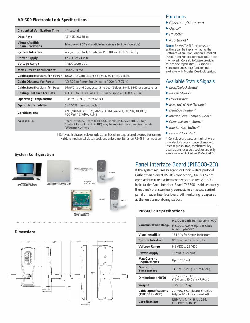
Panel Interface Board (PIB300-2D)If the system requires Wiegand or Clock & Data protocol (rather than a direct RS-485 connection), the AD-Series open architecture platform connects up to two AD-300 locks to the Panel Interface Board (PIB300 - sold separately, if required) that seamlessly connects to an access control panel or reader interface board. All monitoring is captured at the remote monitoring station.
Functions Classroom/Storeroom Office* Privacy*
Apartment*Note: BHMA/ANSI functions such as these can be implemented by the Software when Door Position, Deadbolt Position and/or Interior Push button are monitored. Consult Software provider for specific capabilities. Classroom/Storeroom and Office function not available with Mortise Deadbolt option.
Available Status Signals Lock/Unlock Status†
Request-to-Exit
Door Position
Mechanical Key Override*
Deadbolt Position*
Interior Cover Tamper Guard* Communication Status*
Interior Push Button*
Request-to-Enter* * Consult your access control software provider for specific scope of support. Interior pushbutton, mechanical key override and deadbolt position are only available when linked via PIM400-485.
< 1 secondCredential Verification Time
RS-485 : 9.6 kbpsData Rate
Tri-colored LED’s & audible indicators (field configurable)Visual/Audible Communications
Wiegand or Clock & Data via PIB300, or RS-485 directlySystem Interface
4 VDC to 26 VDCVoltage Range
12 VDC or 24 VDCPower Supply
Up to 250 mAMax Current Requirement
18AWG, 2 Conductor (Belden 8760 or equivalent)Cable Specifications for Power
AD-300 to Power Supply: up to 1000 ft (303 m)Cable Distance for Power
24AWG, 2 or 4 Conductor Shielded (Belden 9841, 9842 or equivalent)Cable Specifications for Data
0 - 100% non-condensingOperating Humidity
ANSI/BHMA A156.25, ANSI/BHMA Grade 1, UL 294, UL10 C, FCC Part 15, ADA, RoHSCertifications
Panel Interface Board (PIB300), Handheld Device (HHD), Dry Contact Relay Board (RLBD) may be required for supervised inputs (Wiegand systems)
Accessories
AD-300 Electronic Lock Specifications
Communication Range
13 LEDs for Status IndicatorsVisual/Audible
Wiegand or Clock & DataSystem Interface
9.5 VDC to 26 VDCVoltage Range
12 VDC or 24 VDCPower Supply
Up to 250 mAMax Current Requirements
-31° to 151°F (-35° to 66°C)Operating Temperature
7.1” x 7.1” x 3.0” (18.0 cm x 18.0 cm x 7.6 cm)
Dimensions (HWD)
1.25 lb (.57 kg)Weight
22AWG, 8 Conductor Shielded (Alpha 1298C or equivalent)
Cable Specifications(PIB300 to ACP)
NEMA 1, 4, 4X, 6; UL 294, FCC Part 15; RoHSCertifications
PIB300-2D Specifications
PIB300 to Lock, RS-485: up to 4000’
PIB300 to ACP, Wiegand or Clock & Data: up to 500’
Dimensions
System Configuration
ACCESS CONTROL PANEL (ACP)
Directly communicates via RS-485
RS-485
AD-300
Wiegand or Clock & Data
PANEL INTERFACEBOARD (PIB300-2D)
AD-300
ACCESS CONTROL MANAGEMENT SYSTEM
AD-300 to PIB300 or ACP, RS-485: up to 4000 ft (1219 m)Cabling Distance for Data
-31° to 151°F (-35° to 66°C)Operating Temperature
† Software indicates lock/unlock status based on sequence of events, but cannot validate mechanical clutch positions unless monitored on RS-485* connection

AD-300 and AD-400 exit trim is exclusively compatible with Von Du-prin 98/99 and 98/99XP (Rim, Mortise, and SVR. CVC and CVR on metal doors only), Von Duprin 22/22F (Rim and SVR) and Falcon 25 (Rim) exit devices made by Inger-soll Rand. The proper low current request to exit switch (RX-LC or AE) is required. Part Numbers for Request to Exit Switch:• Von Duprin: 050281• Falcon: 650359
AD-Series Exit Trim
Mechanical Specifications
Handing
Chassis Cylindrical (Based on Schlage ND-Series)
Meets or exceeds A156.25 and A156.2 Series 4000, Grade 1 strength and operational requirements
2-3/4˝ standard, 2-3/8˝, 3-3/4˝ and 5˝ optional
1/2˝ throw security latch standard, 3/4” throw optional
Pressure cast zinc, plated to match finish symbols
ANSI curved lip strike 1-1/4˝ x 4-7/8˝ x 1-3/16˝ lip to center standard, optional strikes, lip lengths and ANSI strike box available
Mortise (Based on Schlage L-Series)
Meets or exceeds A156.25 and A156.13 Series 1000, Grade 1 operational and security
2-3/4” only
Steel, plated to match finish symbols
ANSI curved lip strike 1-1/4” x 4-7/8” x 1-3/16” lip to center with dust box standard, optional strikes lip lengths available
ANSI Standard
Door Thickness
Backset
Latch Bolt
Levers
Strike
Cylinder & Keys
Handed to Order, Field Reversible
1-3/4” standard, 1-3/8” to 2-3/4” optional (available in 1/8” increments)
Schlage 6-pin Everest C123 keyway cylinder with two patented keys standard Additional options available including Standard, SFIC, FSIC and competitor brands
3/4” throw with anti-friction tongue standard, 1” throw deadbolt on Mortise Deadbolt option*
**Classroom/Storeroom and Office options not available with deadbolt.
Notes:
** FIPS 201-1 Compliant Option Available: The AD-Series can be used in applications which require approval by the U.S. Federal Government under HSPD-12 for FIPS 201-1 Compliance. Specific components are required, please see the AD-401 data sheet or AD-301 data sheet for complete details.
† 75 bit output format default. Configurable to other output formats
Benefits of AD-Series Multi-Technology Readers:• Reads multiple brands of both
proximity (125 kHz) and smart (13.56 MHz) technologies with single device
• AD-Series multi-technology readers are NFC compatible
• Allows end user to migrate to more secure credentials over time and as budgets permit
Additional Readers Magnetic Stripe• Now available with choice of Inser-
tion or Swipe style readers• Triple Track Reader (1, 2 or 3),
field configurable• ABA, ISO76XX Standard• Option for 12 button, 3x4 matrix
backlit keypad
Keypad• Backlit keypad • 12 button, 3x4 matrix
Multi-Technology Reader Specification
Frequency 125 kHz proximity and 13.56 MHz smart card
Standards Standards ISO Standard 15693 and ISO 14443
Maximum Read Range up to 1.25” on 125 kHz proximity, up to 0.75” on 13.56 MHz smart card
125 kHz compatibility Schlage Proximity, XceedID™ Proximity, HID® Proximity, GE/CASI ProxLite®, AWID® Proximity, LenelProx®
13.56 MHz compatibilitySchlage MIFARE® Secure Sector, XceedID™ MIFARE® Secure Sector, aptiQ™ Smart Cards using MIFARE DESFire™ EV1 with PACSA; PIV and PIV-I**†
13.56 MHz compatibility (serial number only)
DESFire® CSN, HID iCLASS® CSN, Inside Contactless PicoTag® CSN, MIFARE®, MIFARE DESFire™ EV1, ST Microelectronics® CSN, Texas Instruments Tag-It® Serial Number, Phillips I-Code® CSN
125 kHz Compatible XceedID Credentials
125 kHz Clamshell, ISO Card, ISO Card w/ Magnetic Stripe, Keyfob, and PVC Disk (7000 Series)
13.56 MHz Compatible aptiQ™ Credentials
aptiQ™ smart cards using MIFARE® in Clamshell, ISO Card, ISO Card w/Magnetic Stripe, Keyfob and PVC Patch (9000 Series); aptiQ™ smart cards using MIFARE DESFire™ EV1 in Clamshell, ISO Card, ISO Card w/ Magnetic Stripe, Keyfob, and PVC Disk (8000 Series)
Certifications/Standards FCC, RSS210, UL 294, Listed, ISO Standard 15693, and ISO Standard 14443
Style/Layout Option for 12 button, 3x4 matrix backlit keypad
Available AD-Series Reader Modules
• Magnetic Stripe (Swipe)
• Magnetic Stripe (Swipe)
KEYPAD+
• Magnetic Stripe (Insertion)
• Keypad• Multi-Technology • Proximity • Smart Card
• Multi-Technology • Proximity • Smart Card
KEYPAD+
• Magnetic Stripe (Insertion)
KEYPAD+

877-671-7011 • securitytechnologies.ingersollrand.com
Selections Correspond With the Numbers Above
Lever styles
Sparta Rhodes
Athens Tubular
Warm tone finishes
Cool tone finishes
605 606 612 643eBright Brass Satin Brass Satin Bronze Aged Bronze
619 625 626 626AMSatin Nickel Bright Satin Chrome Satin Chrome Chrome with Antimicrobial
©2013 Ingersoll Rand 004448 01/13
Standard options are indicated in bold. See price book for specific configuration options.
10 HandingRH Right Handed LH Left HandedField reversible
11 Backset & Latch or Armor FrontCylindrical13-049 2-3/4” Backset, Deadlatch,
Square Corner, 1-1/8” x 2-1/4” Mortise 09-663 Armor Front, 1-1/4” Wide,
Square CornerSee price book for mortise deadbolt and other backset and latch options or armor front options
12 StrikeCylindrical 10-025 1-3/16 Lip, ANSI, No Box,
1-1/4” x 4-7/8” Mortise 10-072 1-3/16” Lip, 1-1/4” x 4-7/8”
Square Corner, Box See price book for other available strikes
13 Door Thickness1-3/4”Other thicknesses available between 1-3/8” and 2-3/4 See price book for detail.
6 LeverSPA SpartaRHO RhodesATH AthensTLR TubularAvailable with knurled surface
7 Finish626 Satin Chrome605 Bright Brass606 Satin Brass612 Satin Bronze619 Satin Nickel625 Bright Chrome643e Aged Bronze626AM Satin Chrome Antimicrobial
8 Lever Cylinder TypePD Schlage 6-pin Full CylinderSee price book for other SFIC, FSIC and Less Cores options available. Compatible with Schlage, Sargent, Corbin, Medeco and Yale
9 Keyway TypeC123 Everest See price book for other available keyway options including master keying
3 ChassisCY CylindricalMS MortiseMD Mortise Deadbolt993R Exit Trim – Rim/CVR/CVC993S Exit Trim – SVR993M Exit Trim – Mortise993DT Non-Functioning Dummy Trim for Exit
4 Function70 Classroom/Storeroom50 Office40 Privacy60 ApartmentLock function capabilities are determined by users access control system
5 ReaderKP KeypadMG Magnetic Stripe (Insertion)MGK Magnetic Stripe + Keypad
(Insertion)MS Magnetic Stripe (Swipe)MSK Magnetic Stripe + Keypad (Swipe)MT Multi-Technology (125 kHz and 13.56 MHz)MTK Multi-Technology + Keypad (125 kHz and 13.56 MHz)DT Dummy Trim
Standard cylinders shown, SFIC and FSIC also available.
INGERSOLL RAND, the Ingersoll Rand logo, SCHLAGE, the SCHLAGE logo, XceedID, Von Duprin, Falcon and aptiQ are trademarks of Ingersoll-Rand plc, its subsidiaries and/or affiliates in the United States and other countries. Inside PicoTag is a trademark of Inside Technologies. GE, CASI and ProxLite are trademarks of General Electric Corporation. MIFARE and MIFARE DESFire EV1 are trademarks of NXP B.V. HID and iCLASS are trademarks of HID Corporation. Tag-It is a trademark of Texas Instruments. STMicroelectronics is a trademark of STMicroelectronics Inc. Infineon and my-d are trademarks of Infineon Technologies. AWID is a trademark of Applied Wireless Identifications Group. All other trademarks are the property of their respective owners.
AD-300-CY-70-MG - SPA-626-PD- C123 -RH - 13-049-10-025-1-3/4Se
ries
Cla
ss
Ch
assi
s
Fun
ctio
n
Rea
der
Leve
r St
yle
Fin
ish
Leve
r C
ylin
der
Key
ing
Typ
e
Han
din
g
Stri
ke
Doo
r T
hic
knes
s
Bac
kset
&
Lat
ch
3 41 2 5 6 7 8 9 10 11 12 13
Ordering InformationAvailable through one of our GSA Schedule 84 approved distributors; BAA Options Available

OverviewAD-Series electronic locks from Schlage are designed to be modular and provide more options to choose from, more functionality in the lock and more compatibility with existing systems. Its patent-pending modular design allows the lock to be customized to fit the needs of an application now, and can change to meet future needs without removing it from the door.
The AD-301 is an ideal solution for applications which require approval by the U.S. Federal Government under HSPD-12 for FIPS 201-1 Compliance. The AD-301 electronic integrated lock with FMK multi-technology reader + keypad is FIPS 201-1 compliant for use in U.S. Federal Agency Buildings using smart card technology. The AD-301 lock with an FMK reader allows both a Wiegand and RS-485 solution.
Factory orderable options include choices of chassis type, network configurations, locking functions, lever styles and finishes. It also offers a wide selection of features that can be configured in the field to customize your openings.
To simplify installation, the AD-Series combines all the hardware components required at the door for a complete access control system into one integrated design that includes the electrified lock, credential reader, request-to-exit and -enter sensors, door position switch, tamper switch and more.
The AD-301 has a number of features built in that are configurable in the field and a long list of items that can be monitored by access control software. Please consult your access control software partner for details on the integration of specific features.
AD-301 FIPS 201-1 Compliant Networked Hardwired Lock with Multi-Technology & Keypad Reader
Features and Benefits
• Open Architecture platform • Panel interface options ensure seamless communication
with your system: - AD-301 locks can wire directly into the RS-485
partners access control panel. - AD-301 in Wiegand solutions will require the use
of a PIB300-2D Panel Interface Board which can support up to 2 AD-301 devices and may require the optional dry-contact relay board (RLBD).
• Real-time communication between access control system and lock
• Field configurable Fail Safe/Fail Secure and other capabilities per code
• Available in cylindrical, mortise, mortise with deadbolt and exit trim
• Compatible with major brands of master key systems• ANSI/BHMA A156.25, ANSI/BHMA Grade 1,
UL 294, UL10C, FCC Part 15, ADA, RoHS, FIPS 201-1
Net
wor
ked
Lock
ing
Solu
tion
s
AD
-301
FIP
S 20
1-1
Com
plia
nt H
ardw
ired

Panel Interface Board (PIB300-2D)If the system requires Wiegand or Clock & Data protocol (rather than a direct RS-485 connection), the AD-Series open architecture platform connects up to two AD-301 locks to the Panel Interface Board (PIB300 - sold separately, if required) that seamlessly connects to an access control panel or reader interface board. All monitoring is captured at the remote monitoring station.
Functions Classroom/Storeroom Office* Privacy*
Apartment*Note: BHMA/ANSI functions such as these can be implemented by the Software when Door Position, Deadbolt Position and/or Interior Push button are monitored. Consult Software provider for specific capabilities. Classroom/Storeroom and Office function not available with Mortise Deadbolt option.
Available Status Signals Lock/Unlock Status†
Request-to-Exit
Door Position
Mechanical Key Override*
Deadbolt Position*
Interior Cover Tamper Guard* Communication Status*
Interior Push Button*
Request-to-Enter* * Consult your access control software provider for specific scope of support. Interior pushbutton, mechanical key override and deadbolt position are only available when connected via RS-485.
< 1 secondCredential Verification Time
RS-485 : 9.6 kbpsData Rate
Tri-colored LED’s & audible indicators (field configurable)Visual/Audible Communications
Wiegand or Clock & Data via PIB300, or RS-485 directlySystem Interface
4 VDC to 26 VDCVoltage Range
12 VDC or 24 VDCPower Supply
Up to 250 mAMax Current Requirement
18AWG, 2 Conductor (Belden 8760 or equivalent)Cable Specifications for Power
AD-301 to Power Supply: up to 1000 ft (303 m)Cable Distance for Power
24AWG, 2 or 4 Conductor Shielded (Belden 9841, 9842 or equivalent)Cable Specifications for Data
0 - 100% non-condensingOperating Humidity
ANSI/BHMA A156.25, ANSI/BHMA Grade 1, UL 294, UL10 C, FCC Part 15, ADA, RoHS, FIPS 201-1Certifications
Panel Interface Board (PIB300), Handheld Device (HHD), Dry Contact Relay Board (RLBD) may be required for supervised inputs (Wiegand systems)
Accessories
AD-301 Electronic Lock Specifications
Communication Range
13 LEDs for Status IndicatorsVisual/Audible
Wiegand or Clock & DataSystem Interface
9.5 VDC to 26 VDCVoltage Range
12 VDC or 24 VDCPower Supply
Up to 250 mAMax Current Requirements
-31° to 151°F (-35° to 66°C)Operating Temperature
7.1” x 7.1” x 3.0” (18.0 cm x 18.0 cm x 7.6 cm)
Dimensions (HWD)
1.25 lb (.57 kg)Weight
22AWG, 8 Conductor Shielded (Alpha 1298C or equivalent)
Cable Specifications(PIB300 to ACP)
NEMA 1, 4, 4X, 6; UL 294, FCC Part 15; RoHS, FIPS 201-1Certifications
PIB300-2D Specifications
PIB300 to Lock, RS485: up to 4000’
PIB300 to ACP, Wiegand or Clock & Data: up to 500’
Dimensions
System Configuration
ACCESS CONTROL PANEL (ACP)
Directly communicates via RS-485
RS-485
AD-301
Wiegand or Clock & Data
PANEL INTERFACEBOARD (PIB300-2D)
AD-301
ACCESS CONTROL MANAGEMENT SYSTEM
AD-301 to PIB300 or ACP, RS-485: up to 4000 ft (1219 m)Cabling Distance for Data
-31° to 151°F (-35° to 66°C)Operating Temperature
† Software indicates lock/unlock status based on sequence of events, but cannot validate mechanical clutch positions unless monitored on RS-485* connection
AD-301 and AD-401 exit trim is exclusively compatible with Von Du-prin 98/99 and 98/99XP (Rim, Mortise, and SVR. CVC and CVR on metal doors only), Von Duprin 22/22F (Rim and SVR) and Falcon 25 (Rim) exit devices made by Inger-soll Rand. The proper low current request to exit switch (RX-LC or AE) is required. Part Numbers for Request to Exit Switch:• Von Duprin: 050281• Falcon: 650359
AD-Series Exit Trim
Mechanical Specifications
Handing
Chassis Cylindrical (Based on Schlage ND-Series)
Meets or exceeds A156.25 and A156.2 Series 4000, Grade 1 strength and operational requirements
2-3/4˝ standard, 2-3/8˝, 3-3/4˝ and 5˝ optional
1/2˝ throw security latch standard, 3/4” throw optional
Pressure cast zinc, plated to match finish symbols
ANSI curved lip strike 1-1/4˝ x 4-7/8˝ x 1-3/16˝ lip to center standard, optional strikes, lip lengths and ANSI strike box available
Mortise (Based on Schlage L-Series)
Meets or exceeds A156.25 and A156.13 Series 1000, Grade 1 operational and security
2-3/4” only
Steel, plated to match finish symbols
ANSI curved lip strike 1-1/4” x 4-7/8” x 1-3/16” lip to center with dust box standard, optional strikes lip lengths available
ANSI Standard
Door Thickness
Backset
Latch Bolt
Levers
Strike
Cylinder & Keys
Handed to Order, Field Reversible
1-3/4” standard, 1-3/8” to 2-3/4” optional (available in 1/8” increments)
Schlage 6-pin Everest C123 keyway cylinder with two patented keys standard Additional options available including Standard, SFIC, FSIC and competitor brands
3/4” throw with anti-friction tongue standard, 1” throw deadbolt on Mortise Deadbolt option*
*Classroom/Storeroom and Office options not available with deadbolt.
Notes:
** The AD-Series FIPS 201-1 Compliant Option can be used in applications which require approval by the U.S. Federal Government under HSPD-12 for FIPS 201-1.
† 75 bit output format default. Configurable to other output formats
FMK Multi-Technology Reader Specification
Frequency 125 kHz proximity and 13.56 MHz smart card
Standards Standards ISO Standard 15693 and ISO 14443
Maximum Read Range up to 1.25” on 125 kHz proximity, up to 0.75” on 13.56 MHz smart card
125 kHz compatibility Schlage Proximity, XceedID™ Proximity, HID® Proximity, GE/CASI ProxLite®, AWID® Proximity, LenelProx®
13.56 MHz compatibility Schlage MIFARE® Secure Sector, XceedID™ MIFARE® Secure Sector, aptiQ™ Smart Cards using MIFARE DESFire™ EV1 with PACSA; PIV and PIV-I**†
13.56 MHz compatibility (serial number only)
DESFire® CSN, HID iCLASS® CSN, Inside Contactless PicoTag® CSN, MIFARE®, MIFARE DESFire™ EV1, ST Microelectronics® CSN, Texas Instruments Tag-It® Serial Number, Phillips I-Code® CSN
125 kHz Compatible XceedID Credentials
125 kHz Clamshell, ISO Card, ISO Card w/ Magnetic Stripe, Keyfob, and PVC Disk (7000 Series)
13.56 MHz Compatible aptiQ™ Credentials
aptiQ™ smart cards using MIFARE® in Clamshell, ISO Card, ISO Card w/Magnetic Stripe, Keyfob and PVC Patch (9000 Series); aptiQ™ smart cards using MIFARE DESFire™ EV1 in Clamshell, ISO Card, ISO Card w/ Magnetic Stripe, Keyfob, and PVC Disk (8000 Series)
Certifications/Standards FCC, RSS210, UL 294, Listed, ISO Standard 15693, and ISO Standard 14443, FIPS 201-1
Style/Layout 12 button, 3x4 matrix backlit keypad
AD-Series FMK Reader Module
• FIPS 201-1 Compliant Multi-Technology• FMK reader required for FIPS 201-1 Compliant
multi-technology & keypad reader supporting both proximity and smart cards
KEYPAD+
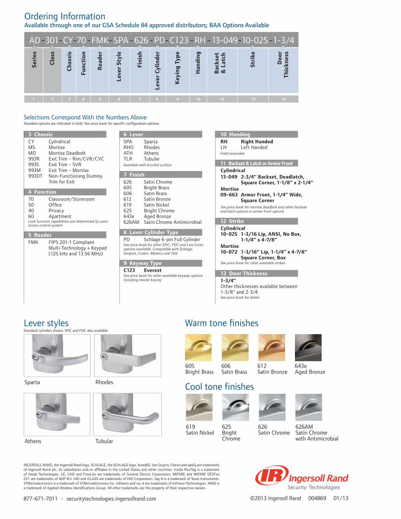
877-671-7011 • securitytechnologies.ingersollrand.com
Selections Correspond With the Numbers Above
Lever styles
Sparta Rhodes
Athens Tubular
Warm tone finishes
Cool tone finishes
605 606 612 643eBright Brass Satin Brass Satin Bronze Aged Bronze
619 625 626 626AMSatin Nickel Bright Satin Chrome Satin Chrome Chrome with Antimicrobial
©2013 Ingersoll Rand 004869 01/13
Standard options are indicated in bold. See price book for specific configuration options.
10 HandingRH Right Handed LH Left HandedField reversible
11 Backset & Latch or Armor FrontCylindrical13-049 2-3/4” Backset, Deadlatch,
Square Corner, 1-1/8” x 2-1/4” Mortise 09-663 Armor Front, 1-1/4” Wide,
Square CornerSee price book for mortise deadbolt and other backset and latch options or armor front options
12 StrikeCylindrical 10-025 1-3/16 Lip, ANSI, No Box,
1-1/4” x 4-7/8” Mortise 10-072 1-3/16” Lip, 1-1/4” x 4-7/8”
Square Corner, Box See price book for other available strikes
13 Door Thickness1-3/4”Other thicknesses available between 1-3/8” and 2-3/4 See price book for detail.
6 LeverSPA SpartaRHO RhodesATH AthensTLR TubularAvailable with knurled surface
7 Finish626 Satin Chrome605 Bright Brass606 Satin Brass612 Satin Bronze619 Satin Nickel625 Bright Chrome643e Aged Bronze626AM Satin Chrome Antimicrobial
8 Lever Cylinder TypePD Schlage 6-pin Full CylinderSee price book for other SFIC, FSIC and Less Cores options available. Compatible with Schlage, Sargent, Corbin, Medeco and Yale
9 Keyway TypeC123 Everest See price book for other available keyway options including master keying
3 ChassisCY CylindricalMS MortiseMD Mortise Deadbolt993R Exit Trim – Rim/CVR/CVC993S Exit Trim – SVR993M Exit Trim – Mortise993DT Non-Functioning Dummy Trim for Exit
4 Function70 Classroom/Storeroom50 Office40 Privacy60 ApartmentLock function capabilities are determined by users access control system
5 ReaderFMK FIPS 201-1 Compliant Multi-Technology + Keypad (125 kHz and 13.56 MHz)
Standard cylinders shown, SFIC and FSIC also available.
INGERSOLL RAND, the Ingersoll Rand logo, SCHLAGE, the SCHLAGE logo, XceedID, Von Duprin, Falcon and aptiQ are trademarks of Ingersoll-Rand plc, its subsidiaries and/or affiliates in the United States and other countries. Inside PicoTag is a trademark of Inside Technologies. GE, CASI and ProxLite are trademarks of General Electric Corporation. MIFARE and MIFARE DESFire EV1 are trademarks of NXP B.V. HID and iCLASS are trademarks of HID Corporation. Tag-It is a trademark of Texas Instruments. STMicroelectronics is a trademark of STMicroelectronics Inc. Infineon and my-d are trademarks of Infineon Technologies. AWID is a trademark of Applied Wireless Identifications Group. All other trademarks are the property of their respective owners.
AD-301-CY-70-FMK- SPA-626-PD-C123 -RH - 13-049-10-025-1-3/4Se
ries
Cla
ss
Ch
assi
s
Fun
ctio
n
Rea
der
Leve
r St
yle
Fin
ish
Leve
r C
ylin
der
Key
ing
Typ
e
Han
din
g
Stri
ke
Doo
r T
hic
knes
s
Bac
kset
&
Lat
ch
3 41 2 5 6 7 8 9 10 11 12 13
Ordering InformationAvailable through one of our GSA Schedule 84 approved distributors; BAA Options Available

OverviewThe AD-Series Electronic Lock is available in 993 Exit Trim for use on openings that require exit devices for either retrofit or new construction applications. Offline and networked solutions are available.
The 993 Exit Trim was designed to suite with AD-Series cylindrical and mortise locksets to ensure that the facility remains aesthetically consistent.
The AD-Series 993 Exit Trim utilizes universal hardware to simplify installation of offline trim to a variety of exit devices, including Rim style from Von Duprin, Falcon, Sargent®, Precision™ Corbin Russwin®, Dorma®, and Yale®.
Available Exit Trim Styles:• 993R – Rim, Concealed Vertical Cable or Concealed Vertical Rod
(CVC and CVR for metal doors only)• 993S – Surface Vertical Rod• 993M – Mortise
* For metal doors only † Narrow design & reversible rim exits not compatible
The proper low current request to exit switch (RX-LC) is required for AD-300/301 and AD-400/401.
Part Numbers for Request to Exit Switch:• Von Duprin: 050281• Falcon: 650359
AD-Series Exit Trim Compatibility
Features and Benefits
• Multiple Credential Reader Options • Offline and Networked Communication Options • A wide variety of finishes and lever styles• Power options that include hardwired (12 VDC or 24
VDC) or batteries (4AA or 8AA)• Compatible with most Standard, FSIC or SFIC keyways
from major brands of master key systems including Schlage, Sargent®, Corbin®, Medeco® and Yale®
CompatibilityDevices AD-200/250 AD-300/301 AD-400/401
Von Duprin 98/99 and 98/99XP Rim/SVR/CVR*/CVC*/Mortise
X X X
Von Duprin 22/22F Rim/SVR X X X
Falcon 25 Rim X X X
Sargent® 80† Rim X
Precision™ 21 Rim (2100 converts to 21 with Precision’s BP21 kit)
X
Yale® 7000 Rim X
Corbin Russwin® 5000 Rim X
Dorma® 9300 Rim X
Stan
dalo
ne L
ocki
ng S
olut
ions
AD
-Ser
ies
Exit
Trim

877-671-7011 • securitytechnologies.ingersollrand.com ©2013 Ingersoll Rand 004382 01/13
DIMENSIONS
Exterior View
AD-Series - 993 Exit Trim
Interior View
AD-200/250/300*/301* - all styles
Interior View
AD-400/401 all styles
Side View
AD-200/250/300*/ 301* - RIM/CVR/CVC or Mortise
Side View
AD-400/401 RIM/CVR/CVC or Mortise
Side View
AD-200/250/300*/ 301* SVR
Side View
AD-400/401 SVR
Available AD-Series Reader Modules
• Multi-Technology (125 kHz proximity and 13.56 MHz smart card)
• FIPS 201-1 Compliant Multi-Technology (125 kHz proximity and 13.56 MHz smart card) sold complete with AD-301 and AD-401 only
• Magnetic Stripe • Keypad Only • All credential readers available + Keypad * unlike other AD-Series chassis styles,
upgrading reader modules on the 993 Exit Trim requires the exterior escutcheon to be removed from the door
Available Communication Options
• AD-400: Networked Wireless Locks• AD-401: Networked Wireless Locks -
FIPS 201-1 compliant • AD-300: Networked Hardwired Locks• AD-301: Networked Hardwired Locks -
FIPS 201-1 compliant • AD-250: Offline, access rights stored
on the magnetic stripe credential• AD-200: Offline, access rights stored
on the lockProfile View
* AD-300/301 includes LED indicatorNote: (2) #7 fasteners with decorative washers located 11.88” below bottom edge of lockINGERSOLL RAND, the Ingersoll Rand logo, SCHLAGE, the SCHLAGE logo, Von Duprin and Falcon are trademarks of Ingersoll-Rand plc, its subsidiaries and/or affiliates in the United States and other countries. Sargent is a trademark of Sargent Manufacturing Company. Precision is a trademark of Stanley Black & Decker. Yale is a trademark of Tale Security, Inc. Corbin Russwin is a trademark of Corbin Russwin, Inc. Dorma is a trademark of DORMA Door Controls, Inc. All other trademarks are the property of their respective owners.

PIM400-485 Panel Interface ModuleFor RS-485 Communication
Features and Benefits
• 900 MHz Spread Spectrum RF technology for long range, reliable communications
• Automatic linking to remote wireless access points with 10 channel frequencies to select from enables easy commissioning
• AES-128 bit Encrypted Spread Spectrum transmissions• 5 visual indicators to quickly pinpoint and display status • Flash memory for easy firmware upgrades• Certifications
- NEMA 1, 4, 4X, 6 - UL 294 - FCC Part 15 - RoHS
OverviewThe PIM400-485 seamlessly integrates to select access control panels via RS-485, eliminating the need for reader interface modules. Each PIM400-485 supports up to 16 wireless access devices such as AD-400/401 locks.
ReliabilityReliable communications result from several technological advances and incorporated features. 900 MHz spread spectrum technology enables high transmission power in a license-free band. Error detection algorithm maintains data integrity on each transmission and redundant transmissions ensure communication success. Periodic “heartbeat” signals provide supervision and assure reliable RF communications are maintained. Lastly, Dynamic Channel Switching (DCS) can be enabled to overcome harsh RF environments by automatically changing channels to avoid potential interference.
SecurityUsed extensively by government and military organizations, spread spectrum technology provides significant security advantages over conventional transmission methods. Wireless access devices utilize spread spectrum transmissions, which are encrypted with AES 128-bit keys, to yield a system that is virtually uncompromisable. In addition, scalability is virtually unlimited as each AD-Series wireless access module has nearly a million addresses to choose from during the linking process.
Centralized Lock/Unlock Command in 10 Seconds or LessPatent-pending Wake-up On Radio (WOR) feature drives communication from the PIM400 to any or all linked wireless devices in 10 seconds or less. This innovative feature works efficiently in parallel with periodic “heartbeat” to maintain up to 2 year battery life on wireless devices such as the AD-400/401 locks. Response rate can be field configured down to 1 second with consideration of battery life. When Wake-up On Radio is used in critical applications Dynamic Channel Switching should also be enabled.
Net
wor
ked
Lock
ing
Solu
tion
s
PIM
400-
485
Pane
l Int
erfa
ce M
odul
e

877-671-7011 • securitytechnologies.ingersollrand.com ©2012 Ingersoll Rand 004447 06/12
ADDITIONAL FEATURES
Reliable Communications900 MHz band enables longer transmission ranges. In general, signal propagation with longer wavelengths travel a greater distance and penetrate through, and around objects better than signals with shorter wavelengths.
Online Communications (Heartbeat)Regular communications between the AD-Series wireless a ccess module and PIM400 monitor transmission presence and integrity. Online communications enable the PIM400 to download information or instructions such as unlock and relock.
Auto Addressing (Linking)One of the final steps in the installation process is called “linking”. Linking ties a specific wireless access module to a selected PIM400 and assigns a unique address. There are over 65,000 unique addresses available per channel, providing nearly a million combinations for virtually unlimited scalability.
Assured CommunicationsA Packet-Error-Rate-Test (PERT) is performed during linking at reduced power levels to ensure reliable communication during operation.
Encoded TransmissionsEach RF transmission is encrypted with AES-128 bit keys to provide virtually uncompromisable security.
TamperThe PIM400 cover is monitored by a tamper switch.
Visual Indications• Power on• Microprocessor running• Linking status• PIM receiving RF data• PIM transmitting RF data• PIM receiving RS-485 data• PIM transmitting RS-485 data• PIM firmware version
• PIM tamper status
Access Point Status Available Through RS-485 Connection• Card and Keypad Data• Door position• Loss of RF communication• Request-to-Exit• Request-to-Enter • Low battery• PIM tamper• Mechanical Key override• Deadbolt position• Interior Cover tamper guard• Lock/Unlock status• Interior push button
Configurable Items from PIM400-485• Wake up On Radio (WOR)• Heartbeat frequency• Relock parameters• Card data format conversion• Extended unlock• Fail Safe/Fail Secure/Fail As-Is• Door held pre-alarm• Cache memory parameters• Dynamic channel switching (DCS)• Reader Configuration• Keypad Configuration• Inside pushbutton configuration• User interface configuration
PIM400-485 Specifications
Frequency Range 902-928 MHz
Modulation 900 MHz spread spectrum, direct sequence, 10 channels
RF Interference Avoidance Optional Dynamic Channel Switching
Transmission/Encryption AES-128 bit Key (optional)
Credential Verification Time < 1 second*
Communication Range
Up to 200 ft (61 m) with obstructions
Up to 1000 ft (305 m) clear line of site
Up to 2000 ft (609 m) line of site with high gain antenna on PIM400
Up to 4000 ft (1219 m) line of site with high gain antennas on PIM400 and WRI400
Visual/Audible Communications 5 LEDs for Status Indicators
System Interface RS-485
Power Supply 12 VDC or 24 VDC
Voltage Range 9.5 VDC to 26 VDC
Max Current Requirement Up to 250 mA
Operating Temperature -31° to 151°F (-35° to 66°C)
Operating Humidity 0 - 100% condensing
Dimensions (HWD) 7.1” x 7.1” x 3.0” (18.0 cm x 18.0 cm x 7.6 cm)
Weight 1.25 lb (.56 kg)
Cable Specifications
DC Power Input: 18AWG, 2 Conductor (Belden 8760 or equivalent) up to 1000 ft (305 m)
PIM400-485 to ACP: 24AWG, 2 or 4 Conductor Shielded (Belden 9842, 9841 or equivalent) up to 4000 ft (1219 m)
Data Rate RF: 40 kbps; RS-485: 9.6 kbps
Certifications NEMA 1, 4, 4X, 6; UL 294, FCC Part 15; Canada RSS 210, RoHS
*Dependant on latency time of access control panel.
ORDERING INFORMATION
PIM400-485 – Panel Interface Module with outdoor enclosure standard. Supports up to 16 access points via RS-485 with select brands of access control panels.
Optional Accessories
• ANT400-REM-I/O – Omni-directional remote indoor/ outdoor antenna module. Requires available Grounding Kit (MGB+MCA5) for outdoor installations
• ANT400-REM-I/O+6DB – Directional, flat panel, remote indoor/outdoor antenna with 6db of gain. Requires available Grounding Kit (MGB+MCA5) for outdoor installations
• MGB+MCA5 – Grounding Kit for outdoor installations• ANT400-REM-Ceiling – Omni-directional ceiling mount indoor
remote antenna• ANT400-REM-Hall – Bi-directional indoor hall application remote
antenna• HHD KIT – Handheld Device with SUS installed and HH-USB cable• 593PI-12DC – 12 VDC power supply

PIM400-TD2 Panel Interface ModuleWiegand or Clock & Data Communication
Features and Benefits
• 900 MHz spread spectrum RF technology for long range, reliable communications
• Supports up to two AD-Series wireless devices• Automatic linking to remote wireless access points with
10 channel frequencies to select from enables easy commissioning
• AES-128 bit encrypted spread spectrum transmissions• 13 visual indicators to quickly verify operation and
troubleshoot • Flash memory for easy software upgrades• Certifications:
- NEMA 1, 4, 4X, 6; UL 294, FCC Part 15; RoHS
OverviewThe PIM400-TD2 seamlessly integrates to virtually any access control panel and their reader interface modules via Wiegand or Clock & Data protocols. Each PIM400-TD2 supports up to two wireless access devices such as AD-400/401 series locks.
Reliability Reliable communications result from several technological advances and incorporated features. 900 MHz spread spectrum technology enables high transmission power in a license-free band. Error detection algorithm maintains data integrity on each transmission and redundant transmissions ensure communication success. Periodic “heartbeat” signals provide supervision and assure reliable RF communications are maintained. Lastly, Dynamic Channel Switching (DCS) can be enabled to overcome harsh RF environments by automatically changing channels to avoid potential interference.
Security Used extensively by government and military organizations, spread spectrum technology provides significant security advantages over conventional transmission methods. Wireless access devices utilize spread spectrum transmissions, which are encrypted with AES-128 bit keys, to yield a system that is virtually uncompromisable. In addition, scalability is virtually unlimited as each AD-Series wireless access module has nearly a million addresses to choose from during the linking process.
Centralized Lock/Unlock Command in 10 Seconds or LessPatent-pending Wake-up On Radio (WOR) feature drives communication from the PIM400 to any or all linked wireless devices in 10 seconds or less. This innovative feature works efficiently in parallel with periodic “heartbeat” to maintain up to 2 year battery life on wireless devices such as the AD-400/401 locks. Response rate can be field configured down to 1 second with consideration of battery life. When Wake-up On Radio is used in critical applications Dynamic Channel Switching should also be enabled.
Net
wor
ked
Lock
ing
Solu
tion
s
PIM
400-
TD2
Pane
l Int
erfa
ce M
odul
e
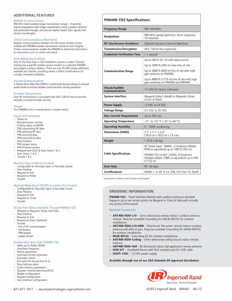
877-671-7011 • securitytechnologies.ingersollrand.com ©2012 Ingersoll Rand 004441 06/12
ADDITIONAL FEATURESReliable Communications900 MHz band enables longer transmission ranges. In general, signal propagation with longer wavelengths travel a greater distance and penetrate through, and around objects better than signals with shorter wavelengths.
Online Communications (Heartbeat)Regular communications between the AD-Series wireless access module and PIM400 monitor transmission presence and integrity. Online communications enable the PIM400 to download information or instructions such as unlock and relock.
Auto Addressing (Linking)One of the final steps in the installation process is called “linking”. Linking ties a specific wireless access module to a selected PIM400 and assigns a unique address. There are over 65,000 unique addresses available per channel, providing nearly a million combinations for virtually unlimited scalability.
Assured CommunicationsA Packet-Error-Rate-Test (PERT) is performed during linking at reduced power levels to ensure reliable communication during operation.
Encoded TransmissionsEach RF transmission is encrypted with AES-128 bit keys to provide virtually uncompromisable security.
TamperThe PIM400 cover is monitored by a tamper switch.
Visual LED Indications• Power on• Microprocessor running• Linking status to WAPM• PIM transmitting RF data• PIM receiving RF data• PIM receiving data• PIM transmitting data• Door Position• PIM tamper status• PIM firmware version• Wiegand and Clock & Data Status 1 & 2• Door Status 1 & 2• Trouble 1 & 2
Standard Open Collector Contacts• Configurable for Normally Open or Normally Closed• Door Position • Request-to-Exit• Request-to-Enter• Trouble
Optional Relay Board (RLBD) to achieve Dry Contact • Configurable for Normally Open or Normally Closed• Door Position • Request-to-Exit• Request-to- Enter• Trouble
Access Point Status Available Through PIM400-TD2 • Wiegand or Magnetic Stripe Card Data• Door Position• Request-to-Exit• Request-to-Enter (optional)• Trouble - loss of RF communication - low battery - PIM tamper - reader tamper
Configurable Items from PIM400-TD2• Wake up On Radio (WOR)• Heartbeat frequency• Relock parameters• Card data format conversion• Extended unlock• Fail Safe/Fail Secure/Fail As-Is• Door held pre-alarm• Cache memory parameters• Dynamic channel switching (DCS)• Reader Configuration• Keypad Configuration• User interface configuration
PIM400-TD2 Specifications
Frequency Range 902-928 MHz
Modulation 900 MHz spread spectrum, direct sequence, 10 channels
RF Interference Avoidance Optional Dynamic Channel Switching
Transmission/Encryption AES-128 bit Key (optional)
Credential Verification Time < 1 second*
Communication Range
Up to 200 ft (61 m) with obstructions
Up to 1000 ft (305 m) clear line of site
Up to 2000 ft (609 m) line of site with high gain antenna on PIM400
Up to 4000 ft (1219 m) line of site with high gain antennas on PIM400 and WRI400
Visual/Audible Communications 13 LEDs for Status Indicators
System Interface Wiegand (data1/data0) or Magnetic Stripe (Clock & Data)
Power Supply 12 VDC or 24 VDC
Voltage Range 9.5 VDC to 26 VDC
Max Current Requirement Up to 250 mA
Operating Temperature -31° to 151°F (-35° to 66°C)
Operating Humidity 0 - 100% condensing
Dimensions (HWD) 7.1” x 7.1” x 3.0” (18.0 cm x 18.0 cm x 7.6 cm)
Weight 1.25 lb (.56 kg)
Cable Specifications
DC Power Input: 18AWG, 2 Conductor (Belden 8760 or equivalent) up to 1000 ft (303 m)
PIM400-TD2 to ACP: 22AWG, 8 Conductor Shielded (Alpha 1298C or equivalent) up to 500 ft (152 m)
Data Rate RF: 40 kbps
Certifications NEMA 1, 4, 4X, 6; UL 294, FCC Part 15; RoHS
*Dependant on latency time of access control panel.
ORDERING INFORMATION
PIM400-TD2 – Panel Interface Module with outdoor enclosure standard. Supports up to two access points via Wiegand or Clock & Data with virtually any access control panel.
Optional Accessories
• ANT400-REM-I/O – Omni-directional remote indoor/ outdoor antenna module. Requires available Grounding Kit (MGB+MCA5) for outdoor installations
• ANT400-REM-I/O+6DB – Directional, flat panel, remote indoor/outdoor antenna with 6db of gain. Requires available Grounding Kit (MGB+MCA5) for outdoor installations
• MGB+MCA5 – Grounding Kit for outdoor installations• ANT400-REM-Ceiling – Omni-directional ceiling mount indoor remote
antenna• ANT400-REM-Hall – Bi-directional indoor hall application remote antenna• HHD KIT – Handheld Device with SUS installed and HH-USB cable• 593PI-12DC – 12 VDC power supply
Available through one of our GSA Schedule 84 approved distributors
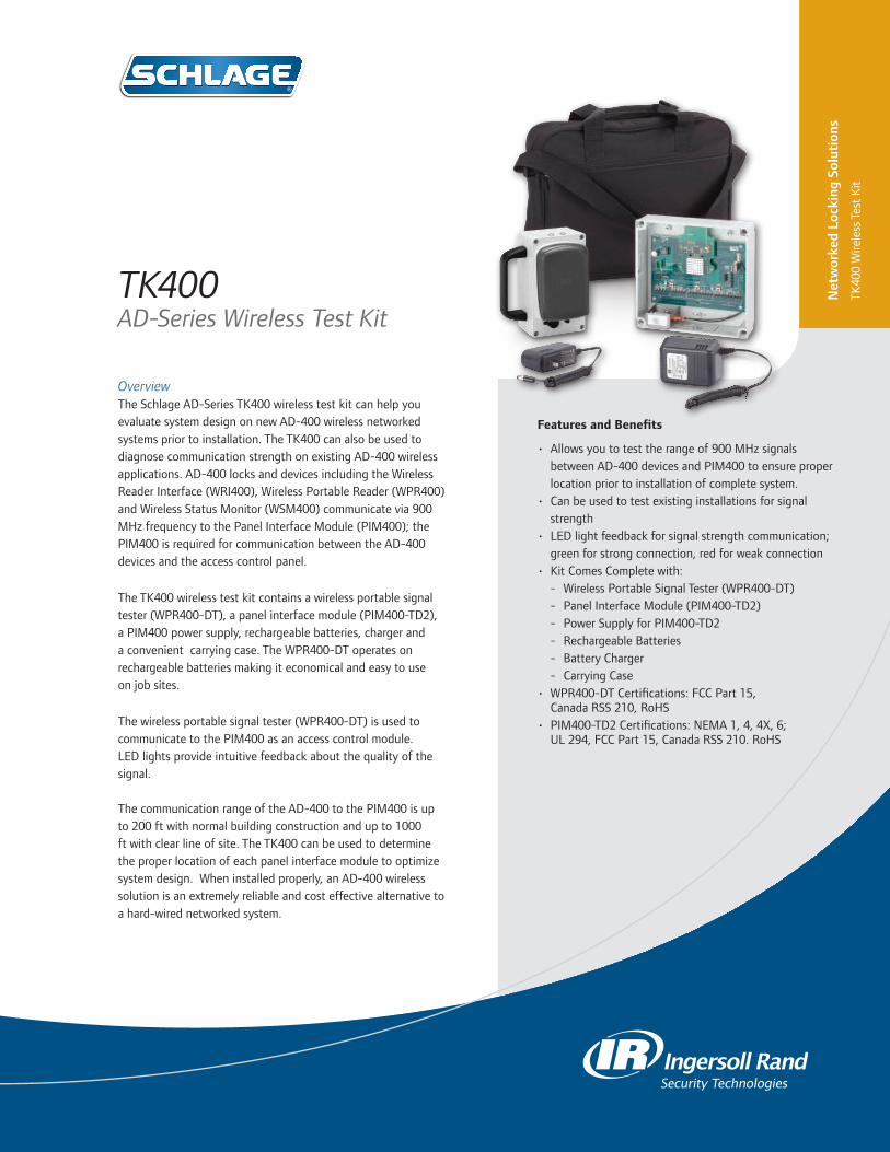
OverviewThe Schlage AD-Series TK400 wireless test kit can help you evaluate system design on new AD-400 wireless networked systems prior to installation. The TK400 can also be used to diagnose communication strength on existing AD-400 wireless applications. AD-400 locks and devices including the Wireless Reader Interface (WRI400), Wireless Portable Reader (WPR400) and Wireless Status Monitor (WSM400) communicate via 900 MHz frequency to the Panel Interface Module (PIM400); the PIM400 is required for communication between the AD-400 devices and the access control panel.
The TK400 wireless test kit contains a wireless portable signal tester (WPR400-DT), a panel interface module (PIM400-TD2), a PIM400 power supply, rechargeable batteries, charger and a convenient carrying case. The WPR400-DT operates on rechargeable batteries making it economical and easy to use on job sites.
The wireless portable signal tester (WPR400-DT) is used to communicate to the PIM400 as an access control module. LED lights provide intuitive feedback about the quality of the signal.
The communication range of the AD-400 to the PIM400 is up to 200 ft with normal building construction and up to 1000 ft with clear line of site. The TK400 can be used to determine the proper location of each panel interface module to optimize system design. When installed properly, an AD-400 wireless solution is an extremely reliable and cost effective alternative to a hard-wired networked system.
TK400AD-Series Wireless Test Kit
Features and Benefits
• Allows you to test the range of 900 MHz signals between AD-400 devices and PIM400 to ensure proper location prior to installation of complete system.
• Can be used to test existing installations for signal strength
• LED light feedback for signal strength communication; green for strong connection, red for weak connection
• Kit Comes Complete with: - Wireless Portable Signal Tester (WPR400-DT) - Panel Interface Module (PIM400-TD2) - Power Supply for PIM400-TD2 - Rechargeable Batteries - Battery Charger - Carrying Case
• WPR400-DT Certifications: FCC Part 15, Canada RSS 210, RoHS
• PIM400-TD2 Certifications: NEMA 1, 4, 4X, 6; UL 294, FCC Part 15, Canada RSS 210. RoHS
Net
wor
ked
Lock
ing
Solu
tion
s
TK40
0 W
irele
ss T
est
Kit
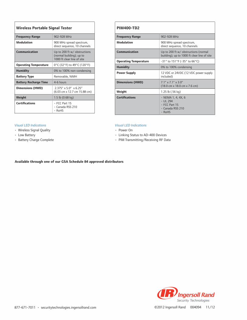
877-671-7011 • securitytechnologies.ingersollrand.com ©2012 Ingersoll Rand 004094 11/12
Wireless Portable Signal Tester
Frequency Range 902-928 MHz
Modulation 900 MHz spread spectrum, direct sequence, 10 channels
Communication Up to 200 ft w/ obstructions (normal building); up to 1000 ft clear line of site
Operating Temperature 0°C (32°F) to 49°C (120°F)
Humidity 0% to 100% non-condensing
Battery Type Removable, NiMH
Battery Recharge Time 4-6 hours
Dimensions (HWD) 2.375” x 5.0” x 6.25”(6.03 cm x 12.7 cm 15.88 cm)
Weight 1.5 lb (0.68 kg)
Certifications • FCC Part 15• Canada RSS 210• RoHS
PIM400-TD2
Frequency Range 902-928 MHz
Modulation 900 MHz spread spectrum, direct sequence, 10 channels
Communication Up to 200 ft w/ obstructions (normal building); up to 1000 ft clear line of site
Operating Temperature -31° to 151°F (-35° to 66°C)
Humidity 0% to 100% condensing
Power Supply 12 VDC or 24VDC (12 VDC power supply included)
Dimensions (HWD) 7.1” x 7.1” x 3.0”(18.0 cm x 18.0 cm x 7.6 cm)
Weight 1.25 lb (.56 kg)
Certifications • NEMA 1, 4, 4X, 6 • UL 294• FCC Part 15• Canada RSS 210• RoHS
Visual LED Indications• Wireless Signal Quality• Low Battery• Battery Charge Complete
Visual LED Indications• Power On• Linking Status to AD-400 Devices• PIM Transmitting/Receiving RF Data
Available through one of our GSA Schedule 84 approved distributors

Features and Benefits
• Fully compatible with Schlage AD-Series Credential Reader Modules & Panel Interface Modules
• Reader options include multi-technology (reads both 13.56 MHz smart card and 125 kHz proximity, magnetic stripe and keypad)
• WPR401 with FIPS 201-1 compliant multi-technology reader is available and must be ordered as a complete unit
• Card reader options available with keypad for multi-factor authentication
• Rechargeable battery and charger (included)• Cache Mode option for offline applications• Field configurable to work as a Wireless Portable
Signal Tester• Configured with Schlage Hand Held Device (HHD)• LED indicators communicate valid (green) and
invalid (red) credential status• Communicates to access control system via PIM400• FCC Part 15, Canada RSS 210, RoHS
OverviewThe Schlage AD-Series Wireless Portable Reader (WPR400) was designed to extend a facility’s access control to remote locations, at a moment’s notice.
The WPR400 is a portable device that utilizes the same credential reader module as an AD-Series electronic lock. The WPR400 can be held by hand or placed in a convenient temporary location to allow for credential verification. Whether it is at a temporary check point or bus load registration, the WPR400 will provide simple, intuitive feedback to the user if the credential being presented is valid or invalid via real time connectivity to the access control system.
The WPR400, as well as other AD-400 locks and devices, communicate via 900 MHz frequency to the Panel Interface Module (PIM400); the PIM400 is required for communication between the AD-400 devices and the access control panel .
The WPR400 was designed to be intuitive to use and easy to set-up, which is critical in situations where there is a need for remote credential verification. At power-on and within range, the WPR400 is ready to accept its first credential within moments of powering up and reconnecting to the previously paired PIM400. After the credential has been authenticated by the access control system, the WPR400 provides intuitive LED light feedback.
The WPR400 also has the ability to be configured to Cache Mode. When enabled, the WPR400 keeps a local database of valid access grants. Upon moving the WPR400 to an offline location away from the PIM400, credentials can be verified for the last 1,000 valid users. Finally, the WPR400 can be manually configured to operate as a wireless portable tester. In Wireless Test Mode, the device can be used to evaluate the location of PIM400s and AD-400 devices within a specific environment, or the existing reader module can remain installed on the WPR400.
WPR400AD-Series Wireless Portable Reader
Net
wor
ked
Lock
ing
Solu
tion
s
WPR
400
Wire
less
Por
tabl
e R
eade
r

877-671-7011 • securitytechnologies.ingersollrand.com ©2013 Ingersoll Rand 004096 01/13
Wireless Portable Reader Specifications
Modulation / Encryption 900 MHz spread spectrum, direct sequence, 10 channels, AES-128 bit Key
Frequency Range 902-928 MHz
Credential Verification Time* < 1 second*
Communication Range Up to 200 ft w/ obstructions (normal building); up to 1000 ft clear line of site
RF Interference Avoidance Configurable Dynamic Channel Switching
Data Rate 40 kbps
Operating Temperature 0ºC (32ºF) to 49ºC (120ºF)
Humidity 0% to 100% non-condensing
Battery Type Rechargeable, Removable, NiMH
Battery Life (fully charged) 100,000 card reads or PIN codes
Battery Recharge Time 4-6 hours
Dimensions – (HWD, less reader) 3.375” x 5.0” x 6.25” (8.57 cm x 12.7 cm 15.88 cm)
Weight – (less reader) 1.5 lb (0.68 kg)
Certifications FCC Part 15, Canada RSS 210, RoHS
Additional Accessories Panel Interface Module (PIM400), Handheld Device (HHD)
Included with WPR400• AD-Series Credential Reader Module
Specified at Ordering• WPR400/TK400 Battery Charger
Modes of Operation• Reader Mode (default)• Wireless Test Mode (field configurable)
ReliabilitySecure and reliable wireless communication with the Panel Interface Module (PIM400) is accomplished using 900 MHz frequency. 900 MHz band enables longer transmission ranges because signal propagation with longer wavelengths travels a greater distance and better penetrates typical building construction – allowing for simplified system design.
Panel Interface Module (PIM400)The PIM400 (sold separately) is required for communication between the WPR400/401 and the access control panel, and can support up to 16 AD-400 devices depending on your access control system.
*WPR requires less than 100 msec, response time does not include latency time of ACP.
ORDERING INFORMATION:Available through one of our GSA Schedule 84 approved distributors
Available AD-Series Reader Modules
Multi-Technology• Proximity• Smart Card
FIPS 201-1 Compliant Multi-Technology• Proximity• Smart Card
Multi-Technology• Proximity• Smart Card
Magnetic Stripe Magnetic Stripe Magnetic Stripe(Swipe)
Magnetic Stripe(Swipe)
Keypad
KEYPAD+
KEYPAD+
KEYPAD+ KEYPAD+
Dummy Trim Reader Module also available. Please see AD-Series Data sheets for more details on credential reader modules.

Overview The WRI400 is a networked access point controller designed to provide wireless connectivity to traditional electronic access control components including credential readers, door position and request to exit switches.
The WRI400 wireless reader interface provides local termination points for your wall or mullion mounted reader, door position switch, request to exit (RX) and reader tamper. The WRI400 communicates data via 900 MHz back to either a PIM400-485 or PIM400-TD2 which are hardwired to the Access Control Panel (ACP) where all access and specific reporting decisions are made and recorded.
The WRI400 is designed to be compatible with most of the popular Wiegand or Clock and Data format readers that exist in the market today. Utilizing the two Form C relays on board expands the capability at the door to control electronic locking hardware as well as other devices such as automatic operators.
The WRI400 allows you to extend the reach of your access control system to openings that are hard to reach with network wiring. Ideal applications include remote doors, historic buildings, gates and elevators. Since the WRI400 is built on an open architecture platform it is designed for seamless integration with most access control systems.
WRI400Wireless Reader Interface
Net
wor
ked
Lock
ing
Solu
tion
s
WR
I400
Wire
less
Rea
der I
nter
face
Features and Benefits
Visual LED Indications • WRI400 cover is monitored by a tamper switch
Encryption• Each RF transmission is encrypted with
AES-128 bit keys
Reader Interfaces Support• Wiegand (data1/data0) up to 255bits• Magnetic Stripe (clock & data) up to 255bits
Form C Relay Outputs• Strike Relay• Auxiliary Output Relay
Signal Inputs• Request-to-Enter• Request-to-Exit• Door Position Switch• Reader Tamper 1• Reader Tamper 2
Certification:• NEMA 1, 4, 4X, 6; UL 294, FCC
Part 15; Canada RSS 210, RoHS
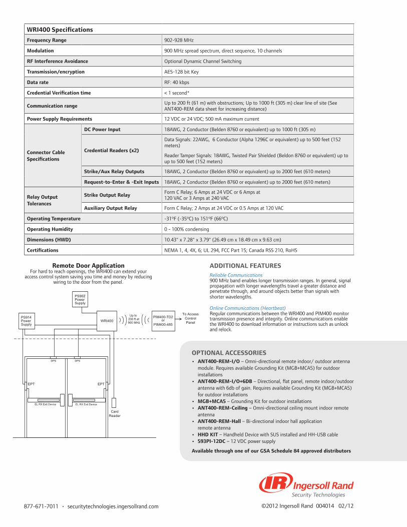
877-671-7011 • securitytechnologies.ingersollrand.com ©2012 Ingersoll Rand 004014 02/12
WRI400 Specifications
Frequency Range 902-928 MHz
Modulation 900 MHz spread spectrum, direct sequence, 10 channels
RF Interference Avoidance Optional Dynamic Channel Switching
Transmission/encryption AES-128 bit Key
Data rate RF: 40 kbps
Credential Verification time < 1 second*
Communication range Up to 200 ft (61 m) with obstructions; Up to 1000 ft (305 m) clear line of site (See ANT400-REM data sheet for increasing distance)
Power Supply Requirements 12 VDC or 24 VDC; 500 mA maximum current
Connector Cable Specifications
DC Power Input 18AWG, 2 Conductor (Belden 8760 or equivalent) up to 1000 ft (305 m)
Credential Readers (x2)
Data Signals: 22AWG, 6 Conductor (Alpha 1296C or equivalent) up to 500 feet (152 meters)
Reader Tamper Signals: 18AWG, Twisted Pair Shielded (Beldon 8760 or equivalent) up to up to 500 feet (152 meters)
Strike/Aux Relay Outputs 18AWG, 2 Conductor (Belden 8760 or equivalent) up to 2000 feet (610 meters)
Request-to-Enter & -Exit Inputs 18AWG, 2 Conductor (Belden 8760 or equivalent) up to 2000 feet (610 meters)
Relay Output Tolerances
Strike Output Relay Form C Relay; 6 Amps at 24 VDC or 6 Amps at 120 VAC or 3 Amps at 240 VAC
Auxiliary Output Relay Form C Relay; 2 Amps at 24 VDC or 0.5 Amps at 120 VAC
Operating Temperature -31ºF (-35ºC) to 151ºF (66ºC)
Operating Humidity 0 - 100% condensing
Dimensions (HWD) 10.43" x 7.28" x 3.79" (26.49 cm x 18.49 cm x 9.63 cm)
Certifications NEMA 1, 4, 4X, 6; UL 294, FCC Part 15; Canada RSS 210, RoHS
ADDITIONAL FEATURESReliable Communications900 MHz band enables longer transmission ranges. In general, signal propagation with longer wavelengths travel a greater distance and penetrate through, and around objects better than signals with shorter wavelengths.
Online Communications (Heartbeat)Regular communications between the WRI400 and PIM400 monitor transmission presence and integrity. Online communications enable the WRI400 to download information or instructions such as unlock and relock.
OPTIONAL ACCESSORIES• ANT400-REM-I/O – Omni-directional remote indoor/ outdoor antenna
module. Requires available Grounding Kit (MGB+MCA5) for outdoor installations
• ANT400-REM-I/O+6DB – Directional, flat panel, remote indoor/outdoor antenna with 6db of gain. Requires available Grounding Kit (MGB+MCA5) for outdoor installations
• MGB+MCA5 – Grounding Kit for outdoor installations• ANT400-REM-Ceiling – Omni-directional ceiling mount indoor remote
antenna• ANT400-REM-Hall – Bi-directional indoor hall application
remote antenna• HHD KIT – Handheld Device with SUS installed and HH-USB cable• 593PI-12DC – 12 VDC power supply
Available through one of our GSA Schedule 84 approved distributors
WRI400
TPETPE
PS902PowerSupply
PS914PowerSupply
CardReader
EL RX Exit Device EL RX Exit Device
PIM400-TD2 or
PIM400-485
Up to 200 ft at900 MHz
To Access Control Panel
DPS DPS
Remote Door ApplicationFor hard to reach openings, the WRI400 can extend your
access control system saving you time and money by reducing wiring to the door from the panel.

OverviewThe gate control kit (GCK400) and the elevator control kit (ECK400) complement and expand the AD-Series platform by bringing wireless access control to applications that are difficult to reach with a traditional wired approach.
The GCK400 and the ECK400 are kits comprised of the wireless reader interface (WRI400), the panel interface module (PIM400-TD2) a remote antenna (ANT-REM I/O) and a power supply (593PI-12DC). The GCK400 kit also includes an antenna grounding kit (MGB+MCA5).
The wireless reader interface (WRI400) is compatible with most popular Wiegand or Clock & Data format credential readers on the market today. The WRI400 communicates via 900MHz to the PIM400-TD2 within a range of up to 1000 feet with a clear line of site. The PIM400-TD2 is hardwired to the access control panel where decisions are validated and recorded.
The GCK400 kit eliminates the need for trenching in gate applications, driving a significant reduction of installation time and cost. The gate kit is ideal for parking lots, airports, military bases and garages. Roadways, parking lots and landscape are left intact since the need to run wires underground is eliminated.
The ECK400 eliminates the need for traveling cables to elevators applications simplifying installation. Access control can be applied to elevators at a much faster rate, reducing downtime and disruption within the facility.
Features and Benefits
• Real time access control• Reduced installation time• Eliminates trenching to gates• Eliminates traveling cables in elevators• 2 reader inputs• Supports all Wiegand (data1/data0) and magnetic
stripe (clock/data) reader technologies
GCK400 & ECK400Wireless Gate Control Kits and Elevator Control Kits
Net
wor
ked
Lock
ing
Solu
tion
s
Wire
less
Gat
e &
Ele
vato
r Con
trol
Kits

877-671-7011 • securitytechnologies.ingersollrand.com ©2012 Ingersoll Rand 004013 11/12
PIM400 - TD2 Specification
Frequency Range 902 - 928 MHz
Transmission / Encryption AES - 128 Bit (optional)
Communication Range
Up to 200ft (61m) with obstructions
Up to 1000ft (305m) clear line of site
Up to 2000ft (609m) line of site with high gain antenna on PIM400
Up to 4000ft (1219m) line of site with high gain antennas on PIM400 and WRI400
Dimensions (HWD)
7.1" X 7.1" X 3.0" (18.0 cm X 18.0 cm X 7.6 cm)
WRI400 Specification
Frequency Range 902 - 928 MHz
Modulation 900 MHz spread spectrum, direct sequence, 10 channels
RF Interference Avoidance Optional Dynamic Channel Switching
Data Rate RF: 40 kbps
Power Supply Requirements 12 VDC or 24 VDC
Dimensions (HWD)
10.43" X 7.28" X 3.79" (26.49cm X 18.49cm X 9.63cm)
Operating Tem-peratures - 31°F (-35°C) to 151°F (66°C)
Strike Output Relay
Form C Relay: 6 Amps at 24 VDC or 6 Amps at 120 VAC or 3 Amps at 240 VAC
Auxillary Output Relay
Form C Relay: 2 Amps at 24 VDC or 0.5 Amps at 120 VAC
Dimensions (Overall):
8.7in x 6.94in x 4.5in (220mm x 176mm x 140mm)
Weight 4.2 oz. (120 grams)
ORDERING INFORMATION
GCK400 Wireless Gate Control Kit
ECK400 Wireless Elevator Control Kit
OPTIONAL ACCESSORIES
ANT400 Hall - Bi-directional indoor antenna ceiling mount
ANT400 –REM – I/O + 6 DB - Directional, flat panel remote indoor/outdoor antenna with 6 DB gain.
MGB + MCA5 - Antenna Grounding Kit for Outdoor Applications
ANT400 – REM-I/O - Omni directional, Flat Panel, Remote Indoor/Outdoor Antenna with Adjustable Mount
Available through one of our GSA Schedule 84 approved distributors
GCK400 Contents
Qty Description
1 ANT400-REM-I/O
1 WRI400
1 PIM400-TD2
1 593PI-12
1 MGB-MCA5
ECK400 Contents
Qty Description
1 ANT400-REM-I/O
1 WRI400
1 PIM400-TD2
1 593Pl-12
ACPPIM400-
TD2
ANT400-REM- I/O with MGB & MCA5 grounding
kit
Up to 1000' clear line of
sight
15' coax cable included with ANT400
Gate
REXGate Relay WRI400
DPS
GCK includes WRI400, PIM400-TD2, ANT-REM I/O, MGB + MCA5 and 593-PI and are shown in RED. Items not included are
in Black. DPS and REX are optional.
UL294 12/24VDC Power supply Building
593-PIPower Supply
aptiQReader
Hardware required:GCK400aptiQ ReaderUL294 12/24 VDC Power SupplyOptional REX and DPSACP
WRI400593-PI
ELEVATOR CAB
aptiQReader
120 VAC
ACP
UL294 12/24 VDC Power
Supply
PIM400-TD2ANT400-REM I/O
15' Coax Cable provided with ANT400
120 VAC
Elev
ator
Sha
ft
ECK400 includes ANT400-REM I/O, WRI400, PIM400-TD2 and 593-PI,
shown in RED.
Up to 1000' clear line of sight
Hardware Required:ECK400UL294 12/24 VDC Power SupplyaptiQ ReaderACP
aptiQ reader and WRI400 reside in or on the elevator cab. ANT400-REM I/O and PIM400-TD2 normally
reside at the top of the elevator shaft.
aptiQ reader transmits card data through WRI400 to PIM400-TD2 then back to ACP. ACP determines if
access is granted and communicates back to elevator cab via separate wiring (not shown here) to either enable floor buttons or direct the elevator cab to a
specific floor.

Features and Benefits
• Use with PIM400, WRI400 and WSM400• Increase installation flexibility• Optimize installation location• Extend communication range with
high-gain antenna• Directional, bi-directional or omni-directional• Indoor and Outdoor options
Included In:• ECK400 Wireless Elevator Kit
• GCK400 Wireless Gate Control Kit
OverviewThe Schlage ANT400-REM optional remote antennas are designed for use with the AD-400 Series devices. They increase installation flexibility of wireless products, extend the range of wireless communication in certain directions and expand the range of applications of AD-Series solution.
A remote antenna is used to improve signal communication strength for wireless communications through an obstruction. A typical application would be when a remote device down a hallway requires a few extra feet of signal strength to reach the PIM400 which is sometimes located around a corner or behind a wire mesh or thick brick construction material.
When increased wireless communication range is required, the ANT400-REM-I/O+6dB model can up to double the range in the line of sight that it is aimed. This “gain antenna” increases the signal strength by focusing the energy a single direction instead of broadcasting in all directions.
AD-Series Remote Antennas are important components to environments with limited installation flexibility. The connected PIM400 can be up to 15ft away from the remote antenna via the included coaxial cable. The outdoor rated antennas create new applications that allow a PIM400 to communicate to external remote access points such as gates or remote buildings without the need to trench cables.
ANT400-REMAD-Series Remote Antennasfor Wireless System
Note: Images not to scale
Net
wor
ked
Lock
ing
Solu
tion
s
AN
T-40
0 R
emot
e A
nten
nas
for W
irele
ss

877-671-7011 • securitytechnologies.ingersollrand.com ©2012 Ingersoll Rand 004095 03/12
Remote Antenna Models
Model Description
ANT400-REM-I/O
Type Omni-directional, unity gain Intended Use: An omni-directional flat-panel antenna for use with indoor or outdoor applications. To be mounted vertically on a wall or post.
Included: antenna, 15ft coax cable, coax whip, articulated wall/post mounting bracket.
Requires Grounding Kit (MGB+MCA5) for outdoor installations.
Communication Range Extension
15ft due to cable length
Location Indoor/Outdoor
Dimensions (HxWxD): 9.1” x 8.4” x 1.2”
Weight: 0.5kg
Temperature Range: -40º C to +65ºC(-40ºF to +150ºF)
ANT400-REM-I/O+6dB
Type Directional, high gainIntended Use: A high gain, directional flat-panel antenna for use with indoor or outdoor applications. To be mounted vertically on a wall or post.
Included: antenna, 15ft coax cable, coax whip, articulated wall/post mounting bracket.
Requires Grounding Kit (MGB+MCA5) for outdoor installations.
Range Extension Up to x2 the original range without antenna (single direction), plus 15ft due to cable length
Location Indoor/Outdoor
Dimensions (HxWxD): 9.1” x 8.4” x 1.2”
Weight: 0.5kg
Temperature Range: -40º C to +65ºC(-40ºF to +150ºF)
ANT400-REM-CEILING
Type Omni-directional, unity gain
Intended Use: An omni-directional antenna for use with indoor applications. To be mounted horizontally on ceiling.
Included: antenna, 15ft coax cable, and coax whip.
Communication Range Extension
15ft due to cable length
Location Indoor
Dimensions (HxWxD): 3.5”(height) x 8.1”(diameter)
Weight: 0.22kg
Temperature Range: -40º C to +65ºC(-40ºF to +150ºF)
ANT400-REM-HALL
Type Bi-directional, unity gain
Intended Use: An bi-directional antenna for use with indoor applications. To be mounted on wall or ceiling.
Included: antenna, 15ft coax cable, and coax whip.
Communication Range Extension
15ft due to cable length
Location Indoor
Dimensions (HxWxD): 7.2” x 3.9” x 4.9”
Weight: 0.24kg
Temperature Range: -10º C to + 65ºC (14º F to + 150º F)
ACCESSORIES
MGB+MCA5 Grounding Kit• The National Electrical Code (NEC) requires that any
outdoor antenna be properly grounded. • The Schlage remote antenna grounding kit is compatible
with all models of remote antenna.
Note: These are the only remote antennas that have been approved by FCC for use with Ingersoll Rand AD-Series 900MHz Communication Modules. Any other antenna with an Ingersoll Rand AD-Series 900MHz Communication Modules would be in violation of FCC regulation.
CERTIFICATION
• FCC Part 15
ANT400-REM-IOANT400-REM-IO+6db
ANT400-REM-CEILING ANT400-REM-HALL
ORDERING INFORMATION:
Available through one of our GSA Schedule 84 approved distributors

Features and Benefits
• Use with PIM400-TD2 or PIB300-2D• Red LED light indicates power status• Longer cycle lifetime than traditional mechanical-based
relay solutions
Access Point Status Signals• Request-to-Enter• Request-to-Exit• Door Position/Status• Tamper Switch
OverviewThe Schlage AD-Series Relay Board (RLBD) supports the open architecture of AD-Series by building a bridge between Schlage technology and third party access control systems that use mechanical, relay-based communication.
The RLBD relay board is used to extend the existing access point status signals on PIM400-TD2 (for AD-400 applications) or PIB300-2D (for AD-300 applications) devices for each access point controlled by the Interface Module.
The optional RLBD relay board removes the need for custom wired relays which can be cumbersome to source, complicated to install, and difficult to troubleshoot. The use of this board over custom wired solutions increases system reliability and reduces installation labor.
The RLBD is not required for integration with access control systems that use signal based communication such as RS485 and Wiegand.
Note: The RLBD does not use mechanical relays which may have different electrical tolerances. Please consider RLBD electrical specifications when implementing this device with another system.
RLBDAD-Series Dry ContactRelay Board
Net
wor
ked
Lock
ing
Solu
tion
s
RLB
D D
ry C
onta
ct R
elay
Boa
rd

877-671-7011 • securitytechnologies.ingersollrand.com ©2012 Ingersoll Rand 004097 11/12
Installation of RLBD in a PIM400-TD2 RLBD Installed in PIM400-TD2
RLBD Specifications
Voltage Maximum (contact-to-contact) 28V
Input Current Maximum 400mA
“Open” State Resistance 5 mega-ohms
“Closed” State Resistance 2 ohms
Dimensions (HWD) 2.1” x 3.5” x 1.0” (5.33 cm x 8.89cm x 2.54 cm)
Weight 0.125 lb (56.7 g)
Operating Temperature -31ºF to 151ºF (-35ºC to 66ºC)
Operating Humidity 0-100% condensing
ORDERING INFORMATION:
Available through one of our GSA Schedule 84 approved distributors

Features and Benefits
• Convenient kit includes the WRI400 & PIM400-TD2• Extends the reach of your access control system to
remote locations without running wires
WRI400• 2 form C relay outputs –strike & auxiliary• Each RF transmission is encrypted with AES-128 bit
keys• Reader Interfaces Support– Wiegand (data1/data0) up
to 255bits & Magnetic Stripe (clock & data) up to 255bits
• UL 294 certified
PIM400-TD2• 900 MHz spread spectrum RF technology for
long range, reliable communications• Supports up to two AD-Series wireless devices• Automatic linking to remote wireless access
points with 10 channel frequencies to select from enables easy commissioning
• AES-128 bit encrypted spread spectrum transmissions
• UL 294 certified
OverviewThe Schlage REPTR400 Wireless Repeater Kit is a simple, all in one package solution for access control applications that require an extended wireless range. The Schlage REPTR400 includes an AD-Series Panel Interface Module (PIM400-TD2) and an AD-Series Wireless Reader Interface (WRI400). The PIM400-TD2 interfaces with most access control systems. The WRI400 gathers signals from around the door components and wirelessly transmits them back to the PIM400-TD2.
The REPTR400 extends the wireless range by receiving information on one radio frequency (RF) channel and retransmits it on another RF channel. Each REPTR400 can extend the wireless range of your access control system by up to 200 feet indoors or up to 1000 feet, line of site.
Use of the REPTR400 allows you to extend the reach of your access control system to remote locations without running wires, thus saving you time and money on installation.
For example, the REPTR400 can be used for gate applications. The PIM400 is located inside of a building up to 500 feet from the access control panel. A remote antenna (sold separately) can be wired into the PIM400 and installed on the exterior of the building. The REPTR400 can be installed at the gate up to 1000 feet away with a clear line of site, connecting the card reader and locking hardware to the WRI400. This solution eliminates the need for considerable trenching and the installation of an access control panel at the gate location, while giving the access control system real-time information at the remote gate.
REPTR400Wireless Repeater Kit
Net
wor
ked
Lock
ing
Solu
tion
s
REP
TR40
0 W
irele
ss R
epea
ter
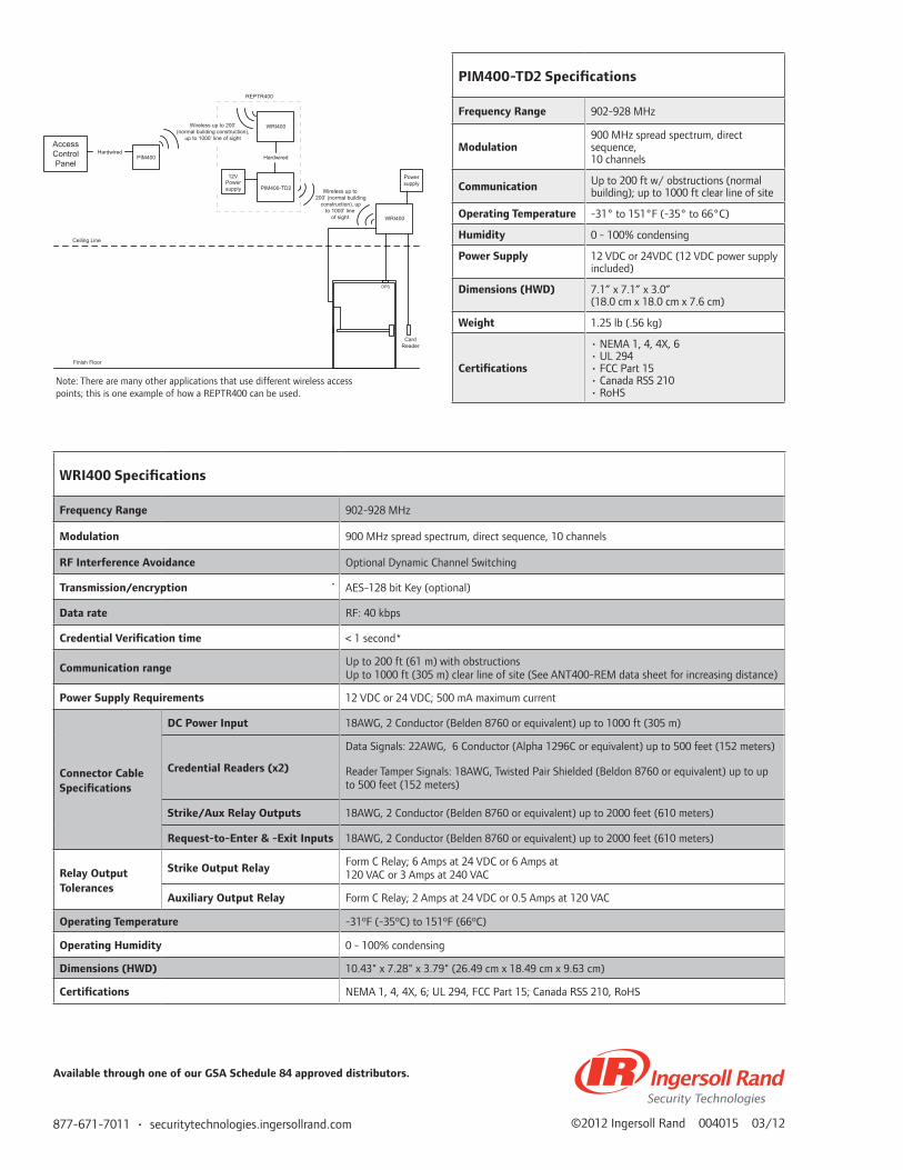
877-671-7011 • securitytechnologies.ingersollrand.com ©2012 Ingersoll Rand 004015 03/12
Card Reader
DPS
AccessControl Panel
PIM400Hardwired
REPTR400
WRI400
PIM400-TD2
Hardwired
WRI400
Power supplyPower
supply
Ceiling Line
Finish Floor
12V
Wireless up to 200’ (normal building construction),
up to 1000’ line of sight
Wireless up to 200’ (normal building
construction), up to 1000’ line
of sight
WRI400 Specifications
Frequency Range 902-928 MHz
Modulation 900 MHz spread spectrum, direct sequence, 10 channels
RF Interference Avoidance Optional Dynamic Channel Switching
Transmission/encryption AES-128 bit Key (optional)
Data rate RF: 40 kbps
Credential Verification time < 1 second*
Communication range Up to 200 ft (61 m) with obstructions Up to 1000 ft (305 m) clear line of site (See ANT400-REM data sheet for increasing distance)
Power Supply Requirements 12 VDC or 24 VDC; 500 mA maximum current
Connector Cable Specifications
DC Power Input 18AWG, 2 Conductor (Belden 8760 or equivalent) up to 1000 ft (305 m)
Credential Readers (x2)
Data Signals: 22AWG, 6 Conductor (Alpha 1296C or equivalent) up to 500 feet (152 meters)
Reader Tamper Signals: 18AWG, Twisted Pair Shielded (Beldon 8760 or equivalent) up to up to 500 feet (152 meters)
Strike/Aux Relay Outputs 18AWG, 2 Conductor (Belden 8760 or equivalent) up to 2000 feet (610 meters)
Request-to-Enter & -Exit Inputs 18AWG, 2 Conductor (Belden 8760 or equivalent) up to 2000 feet (610 meters)
Relay Output Tolerances
Strike Output Relay Form C Relay; 6 Amps at 24 VDC or 6 Amps at 120 VAC or 3 Amps at 240 VAC
Auxiliary Output Relay Form C Relay; 2 Amps at 24 VDC or 0.5 Amps at 120 VAC
Operating Temperature -31ºF (-35ºC) to 151ºF (66ºC)
Operating Humidity 0 - 100% condensing
Dimensions (HWD) 10.43" x 7.28" x 3.79" (26.49 cm x 18.49 cm x 9.63 cm)
Certifications NEMA 1, 4, 4X, 6; UL 294, FCC Part 15; Canada RSS 210, RoHS
PIM400-TD2 Specifications
Frequency Range 902-928 MHz
Modulation900 MHz spread spectrum, direct sequence, 10 channels
Communication Up to 200 ft w/ obstructions (normal building); up to 1000 ft clear line of site
Operating Temperature -31° to 151°F (-35° to 66°C)
Humidity 0 - 100% condensing
Power Supply 12 VDC or 24VDC (12 VDC power supply included)
Dimensions (HWD) 7.1” x 7.1” x 3.0” (18.0 cm x 18.0 cm x 7.6 cm)
Weight 1.25 lb (.56 kg)
Certifications
• NEMA 1, 4, 4X, 6 • UL 294 • FCC Part 15 • Canada RSS 210 • RoHS
Available through one of our GSA Schedule 84 approved distributors.
Note: There are many other applications that use different wireless access points; this is one example of how a REPTR400 can be used.

OverviewSchlage Utility Software (SUS) is designed specifically for use on the Handheld Device (HHD) as the link between your access control management software and Schlage electronic offline and networked locks and accessories. This solution consolidates and simplifies programming and managing your access control system. The SUS and HHD is used to initialize, configure and test product operation, and also provides an easy way to manage people, audits, locks and other network panel interface devices for simple access control. The intuitive screen layout for the SUS provides easy navigation during use.
For offline products the SUS is utilized to transfer access control data, such as authorized user lists, via the HHD to the locks. The SUS is also utilized to download audit trail information from offline devices to the HHD and then transfer that data to the access control management software.
In addition the SUS can configure other networked electronic devices (including PIM and PIB) and update firmware revision updates to the devices as desired.
The HHD connects with Schlage AD-Series electronic locks and accessories via a USB interface and utilizes Active Synch or Win Mobile Device Manager to communicate with your PC via the USB port. The HHD is also able to connect to the SPED, KC2, CM, CL, CT500, CT1000, CL Controller and WA-Series PIMs via a serial cable connection.
Schlage Utility Software (SUS) on the Handheld Device (HHD)
Features and Benefits
• Handheld Device with Schlage Utility Software installed
• Touch Screen operation• Initialize Lock and Accessories with SUS • Configure and Test Devices• New device template simplifies configuration
Stan
dalo
ne/O
fflin
e Lo
ckin
g So
luti
ons
SUS
on t
he H
andh
eld
Dev
ice

877-671-7011 • securitytechnologies.ingersollrand.com ©2012 Ingersoll Rand 004443 03/12
FEATURES AND SPECIFICATIONS
Schlage Utility Software• Initialize Lock and Accessories• Field Configure Devices
- Credential Reader Formats - Lock Function - Unlock Period - Failure Mode - Audible Alarm ON/OFF
• Offline Devices - Manage up to 100 unique door files
- Retrieve Audit trails from up to 100 devices• Networked Devices
- Communication Settings
- Validate Status Monitor• Service & Diagnostics
- Battery Status - Validate hardware and software revision - Troubleshooting Status Signals
- Firmware Upgrades
HHD Specifications• 3.5 in LCD display• Touch Screen with Backlit Keypad• 32-bit processor • Operating System: Windows Mobile 5.0• Memory: 128 MB RAM / 256 MB ROM• Battery: Rechargeable 3.7 V, 1,230mAH, Li-ion• Dimensions (HWD): 5.3” X 2.9” X 0.7”
(13.5 cm x 7.3 cm x 1.8 cm)• Weight: 0.42 lbs (190 g)• 4 ft. (1.2 m) drop to steel surface, 2 drops per 6 sides
How-To-Videos• Specially formatted How-To-Videos for the HHD are
available• They can be downloaded from www.schlage.com/
support• If additional storage is needed, a standard mini SD
memory card can be used• Videos should be saved on the SD card or in a new
folder on the device rather than in the shared sync folder or root directory
ORDERING INFORMATION
HHD KIT – Handheld Device with SUS installed and HH-USB cable
HH-USB – USB Cable
HH-SERIAL – Serial Cable used to connect HHD to CIP
PIMWA-CV – Converter used to connect HH-SERIAL to WA-Series PIM
P512112 – CIP, utilized with HH-SERIAL to connect to CM, CL and KC-2 locks
HHD Compatible Devices and Required Cable and Adaptors
Devices Cable and Adaptors
AD-Series and CO-Series Locks PIM400, WRI400, ECK400, GCK400, WPR400, TK400 and CT5000 controller
HH-USB (included in HHD-Kit)
BE367, KC-2, CM, CL, CT500, CT1000, CL-Controller
HH-Serial + CIP
WA-Series PIM HH-Serial + PIMWA-CV

Stan
dalo
ne L
ocki
ng
Standalone Locking
This section of the Electronic Access Control catalog covers standalone locks, controllers and accessories including the AD-Series, CO-Series and CT5000.
Overview
Standalone access control solutions provide
added security, convenience and efficiency
for openings that do not require real-time
monitoring. They allow you to reduce rekeying
costs by issuing electronic credentials which can
easily be added or deleted at any time. Audit
trails tell you who requested access and when.
You can also save time and money by setting
automatic lock and unlock schedules for specific
time zones and holidays.
Schlage AD-Series and CO-Series are the first
electronic locks to achieve UL 294 certification
which is the standard for safety of access
control units. Both models feature a robust
integrated design which incorporates many of
the components typically found around the
door including the lockset, credential reader
and door position switch. They also offer a
choice of chassis, credential reader, lever and
finish options to meet the needs of a variety of
applications and facilities.
The AD-Series:
Features
The AD-Series is a flexible, adaptable and scalable
solution that provides you with an extended
breadth of options as well as a migration path
to future technologies. It is ideal for applications
with more advanced security needs.
Two different classifications are offered in the AD-
Series for standalone applications. The AD-200 is
a computer managed system where user access
rights are stored in the lock. Modifications to user
access privileges as well as audits are transferred
between the access control software and the lock
with the handheld programming device (HHD).
The AD-250 is a computer managed system where
user access rights are stored on magnetic stripe
cards. The AD-250 is often used in campus-like
environments with a large number of users and
offline openings.
The AD-Series offers keypad, magnetic stripe,
and multi-technology readers (reads both
125 kHz proximity and 13.56 MHz smart). All
AD-Series card readers are all available with dual
authentication for added security (card + PIN).
Benefits
The AD-Series can be customized to meet the
specific needs of each opening in a facility with
a wide variety of factory orderable and field
configurable options. The innovative modular
design of the AD-Series allows you to upgrade
from standalone to networked if your needs
change in the future. The AD-Series also allows
you to upgrade credential readers, for example,
from magnetic stripe to multi-technology.
Macintosh HD:Users:trighter:Documents:_IngersollRand:EAC_Catalog:005023_EAC_Catalog_Standalone_Intro:005427_OA_Standalone_Intro:005427_OA_Standalone_Intro:005427_OA_Standalone_Intro_011113.indd January 11, 2013 9:49 AM Page 51

Stan
dalo
ne L
ocki
ng Options*
The AD-Series has several options to choose from including:
Class: AD-200, AD-250 (For AD-300 and AD-400 Networked Options, see the Networked Locking
Introduction pages of this catalog)
Chassis: Cylindrical, Mortise, Mortise Deadbolt, Exit Trim
Function*: Classroom/Storeroom, Office, Privacy, and Apartment
Readers*: Keypad, magnetic stripe and multi-technology readers (reads both 125 kHz proximity and
13.56 MHz smart). All card readers are available with + PIN option for added security.
Lever Style: Sparta, Rhodes, Athens, Tubular (Tactile warning available)
Finishes: 626 Satin Chrome, 605 Bright Brass, 606 Satin Brass, 612 Satin Bronze, 619 Satin Nickel,
625 Bright Chrome, 643e Aged Bronze, 626AM Satin Chrome with Antimicrobial
*Some options are dependent upon choice class and chassis; see price book for complete details
The CO-Series:
Features
The CO-Series is a reliable, compatible and
proven solution backed by extensive testing and
certification and the strong mechanical heritage
of Schlage. It is ideal for applications that desire a
cost effective solution for basic security needs.
Three different classifications are offered in
the CO-Series for standalone applications. The
CO-100 is a manually programmed keypad only
lock which allows up to 500 unique PIN codes
for user access. The CO-200 can be manually
programmed or computer managed in which
case user access rights are stored in the lock.
Modifications to user access privileges as well
as audits are transferred between the access
control software to the lock with a handheld
programming device (HHD). The CO-250 is a
computer managed system where user access
rights are stored on magnetic stripe cards.
The CO-250 is often used in campus-like
environments with a large number of users and
offline openings.
The CO-Series offers keypad, magnetic stripe and
proximity readers (125 kHz); CO-Series readers
are all available with dual authentication for
added security (card + PIN). The CO-Series is an
excellent choice if the needs of the facility are
not expected to change in the future.
Benefits
The CO-Series provides the added security and
convenience of electronic access control without
the cost or complexity of a networked system. By
providing electronic credentials you can minimize
the number of mechanical keys issued which
protects the integrity of key systems. Choose
from basic PIN code access for a small number
of users or a card based system to serve a larger
population of users.

Stan
dalo
ne L
ocki
ng
Cylinder Compatibility Full Size key-in-lever 6 pin
Full Size key-in-lever 7 pin
FSIC 6 & 7 pin
FSIC 6 & 7 pin
Schlage
Falcon
Sargent® (10L + 11L Full Size)
Corbin Russwin®
Yale® (includes Medeco 31 *0100 FSIC)
Best®
= with cylinder or less cylinder options = less cylinder, only with Sparta and Rhodes levers = less cylinder only
Note: See pricebook for specific configurations.
Exit Trim:
Compatibility
DevicesAD-Series
(AD-200 & AD-250) and CO-Series
Von Duprin 98/99 and 98/99XP Rim/SVR/CVR†/CVC†)/Mortise X
Von Duprin 22/22F Rim/SVR X
Falcon 25 Rim X
Sargent 80 (Narrow design & reversible rim exits not compatible) Rim X
Precision® 21 Rim (2100 converts to 21 with Precision’s BP21 kit) X
Yale 7000 Rim X
Corbin Russwin 5000 Rim X
Dorma® 9300 Rim X
AD-Series & CO-Series Compatibility
Keyway/Cylinders:
*Options may be limited by your choice of class.
†Metal door only
Options*
The CO-Series has several options to choose from including:
Class: CO-100, CO-200, CO-250
Chassis: Cylindrical, Mortise, Mortise Deadbolt, Exit Trim
Function*: Classroom/Storeroom, Office, and Privacy
Readers*: Keypad, magnetic stripe, proximity (125 kHz); all card readers are available with + PIN option
for added security*.
Lever Style: Sparta, Rhodes, Athens, Tubular (Tactile warning available)
Finishes: 626 Satin Chrome, 605 Bright Brass, 606 Satin Brass, 612 Satin Bronze, 619 Satin Nickel,
625 Bright Chrome, 643e Aged Bronze, 626AM Satin Chrome with Antimicrobial

Stan
dalo
ne L
ocki
ng CO-100 CO-200 CO-250 AD-200 AD-250
System Info n/aConsult with OEM Access Control System Provider
for Specific Requirements
Communication to/from Controller n/a Standalone: HHD is the link to the Access Control Software
Device Capacity
Number of Users 500 2000* Unlimited* 5000* Unlimited*
Number of Audits n/a 2000* 4000* 5000* 10000*
Reader Options n/aConsult with OEM Access Control System Provider
for Credential Format Compatibility
Keypad Only Yes
Yes
NoYes
No
Magnetic Stripe Card
No
Yes Yes
125 kHz Proximity Card
No
No
NoMulti-Technology - 125 kHz proximity and 13.56 MHz smart No
Yes
PIV & PIV-I Card Compatible Yes*†
Card + PIN Yes
Status Monitors
Request to Exit
No Yes**Door Position Switch
Interior Cover Tamper Guard
Lock/Unlock Status Clutch Position
Mechanical Key Override (ATK) Yes
Request to Enter No
Battery Status Yes
Battery Voltage Level
No No
Communication Status
Remote Lockdown (from host)
Remote Unlock (from host)
Deadbolt Position
Interior Push Button
Chassis Options
CylindricalYes
Mortise
Mortise Deadbolt No Yes
Exit Trim Yes
Functions n/a Consult with OEM Access Control Provider for Specific Support
Classroom/Storeroom (70) Yes
Privacy (40) No Yes
Office (50) Yes
Apartment (60) No Yes
Accessories n/a Consult with OEM Access Control Provider for Specific Support
HHD - Handheld Programming Device No Yes
*Depending on your access control software **Built in status signals available to enable migration to networked, not monitored in standalone application† 75 bit output format default. Configurable to other output formats. Check with access control provider for specific support
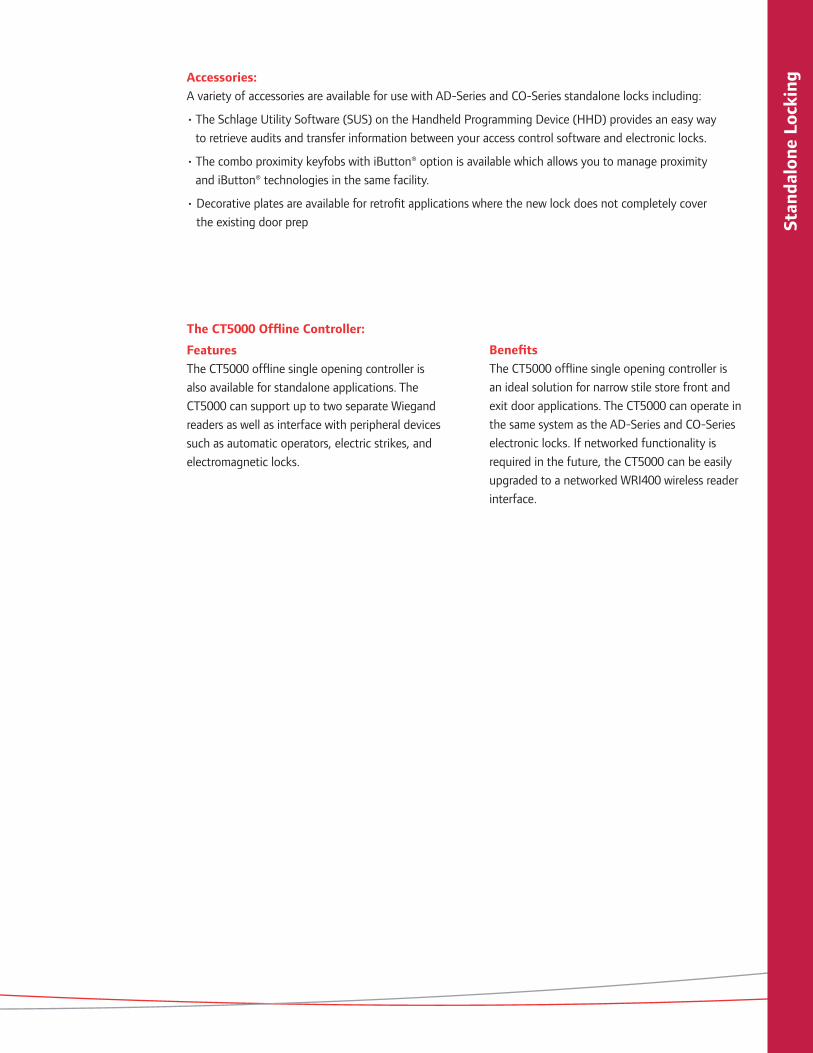
Stan
dalo
ne L
ocki
ngAccessories:
A variety of accessories are available for use with AD-Series and CO-Series standalone locks including:
• The Schlage Utility Software (SUS) on the Handheld Programming Device (HHD) provides an easy way
to retrieve audits and transfer information between your access control software and electronic locks.
• The combo proximity keyfobs with iButton® option is available which allows you to manage proximity
and iButton® technologies in the same facility.
• Decorative plates are available for retrofit applications where the new lock does not completely cover
the existing door prep
The CT5000 Offline Controller:
Features
The CT5000 offline single opening controller is
also available for standalone applications. The
CT5000 can support up to two separate Wiegand
readers as well as interface with peripheral devices
such as automatic operators, electric strikes, and
electromagnetic locks.
Benefits
The CT5000 offline single opening controller is
an ideal solution for narrow stile store front and
exit door applications. The CT5000 can operate in
the same system as the AD-Series and CO-Series
electronic locks. If networked functionality is
required in the future, the CT5000 can be easily
upgraded to a networked WRI400 wireless reader
interface.

Stan
dalo
ne L
ocki
ng
877-671-7011 • securitytechnologies.ingersollrand.com ©2013 Ingersoll Rand 005427 01/13
THIS PAGE IS INTENTIONALLY BLANK.
Macintosh HD:Users:trighter:Documents:_IngersollRand:EAC_Catalog:005023_EAC_Catalog_Standalone_Intro:005427_OA_Standalone_Intro:005427_OA_Standalone_Intro:005427_OA_Standalone_Intro_011113.indd January 11, 2013 9:49 AM Page 56

AD-Series electronic locks from Schlage are designed to be modular and provide more options to choose from, more functionality in the lock and more compatibility with existing systems. Its patent-pending modular design allows the lock to be customized to fit the needs of an application now, and can change to meet future needs without removing it from the door.
Factory orderable options include choices of credential readers, chassis type, locking functions, power options, lever styles and finishes. It also offers a wide selection of features that can be configured in the field to customize your openings.
The AD-200 is a simple, economical solution if no access control system currently exists in facility, or for openings that don’t require the control of a networked solution. The AD-200 is easily upgradable to a networked lock if requirements change in the future.
On all AD-Series standalone locks, Schlage has built in many of the incremental features needed in a networked system such as request-to-exit and -enter sensors, interior cover tamper guard, as well as the door position switch. This way, if the customer chooses to network this opening in the future, all the components will be there to make the transition an easy one.
AD-200 Standalone Electronic Lock
Features and Benefits
• Security that’s more intelligent and convenient than traditional mechanical locking devices
• Audit trail reports that allow you to track usage and events
• Update users and access rights at the lock using the keypad or handheld device
• The ability to upgrade to a networked solution without removing the lock from the door
• Available in cylindrical, mortise, mortise with deadbolt and exit trim
• Compatible with major brands of master key systems and exit devices
• Now available with Magnetic Swipe Reader• AD-Series with multi-technology readers are NFC
compatible• ANSI/BHMA A156.25, ANSI/BHMA Grade 1, UL
294,UL10C, FCC Part 15, ADA, RoHS
Stan
dalo
ne L
ocki
ng S
olut
ions
AD
-200
Sta
ndal
one

Dimensions
Schlage Utility Software on Handheld Device
The Schlage Utility Software (SUS) on the Handheld Device (HHD) provides an easy way to manage people, audits and locks for simple access control management.
HHD is also compatible with CM, CL, VIP, WA and KC2 Series locks in a serial cable connection.
Schlage Utility Software
• Initialize Lock and Accessories• Field Configure Devices
- Credential Reader Formats - Lock Function - Unlock Period - Failure Mode - Audible Alarm ON/OFF
• Service & Diagnostics - Battery Status - Validate hardware and software revision
- Troubleshooting Status Signals• New device template simplifies configuration
HHD
• 3.5 in LCD display• Touch Screen/Keypad Backlit• 32-bit processor • OS: Windows Mobile 5.0• Memory: 128 MB RAM/256 MB ROM• Battery: Rechargeable 3.7 v,
1,230 mAH, Li-ion• Dimensions: 5.3” x 2.9” x 0.7”
(13.5 cm x 7.3 cm x 1.8 cm)• Weight: 0.42 lbs. (190 g)• 4 ft. (1.2 m) drop to steel surface,
2 drops per 6 sides
The HHD connects with AD-Series and CO-Series locks and accessories via the USB interface
Functions Classroom/Storeroom
Office
Privacy
Apartment
Note: Classroom/Storeroom and Office function not available with Mortise Deadbolt option. To ensure safety, all functions always allow for free egress.
Standard Status Signals Lock/Unlock Status
Mechanical Key Override
Battery Status
AD-200 Electronic Lock Specifications
Users Up to 5,000
Audits Up to 5,000
Credential Verification Time ≤ 1 second*
Visual/Audible Communications Tri-colored LED’s & audible indicators (field configurable)
System Interface Handheld Device
Power Supply 4AA, 8AA, 12 VDC or 24 VDC
Voltage Range 4 VDC to 26 VDC
Max Current Requirement Up to 250 mA
Battery Life Up to 2 yrs with 4AA
Operating Temperature - Exterior -31° to 151°F (-35° to 66°C)
Operating Temperature - Interior 32° to 120°F (0° to 49°C) (battery)
Operating Humidity 0 - 100% non-condensing
Certifications ANSI/BHMA A156.25, ANSI/BHMA Grade 1, UL 294, UL10 C, FCC Part 15, ADA, RoHS
Accessories Handheld Device (HHD)
* Verification time is dependent on size of user base

Multi-Technology Reader Specification
Frequency 125 kHz proximity and 13.56 MHz smart card
Standards Standards ISO Standard 15693 and ISO 14443
Maximum Read Range up to 1.25” on 125 kHz proximity, up to 0.75” on 13.56 MHz smart card
125 kHz compatibilitySchlage Proximity, XceedID™ Proximity, HID® Proximity, GE/CASI ProxLite®, AWID® Proximity, LenelProx®
13.56 MHz compatibilitySchlage MIFARE® Secure Sector, XceedID™ MIFARE® Secure Sector, aptiQ™ Smart Cards using MIFARE DESFire™ EV1 with PACSA; PIV and PIV-I*†
13.56 MHz compatibility (serial number only)
DESFire® CSN, HID iCLASS® CSN, Inside Contactless PicoTag® CSN, MIFARE®, MIFARE DESFire™ EV1, ST Microelectronics® CSN, Texas Instru-ments Tag-It® Serial Number, Phillips I-Code® CSN
125 kHz Compatible XceedID Credentials
125 kHz Clamshell, ISO Card, ISO Card w/ Magnetic Stripe, Keyfob, and PVC Disk (7000 Series)
13.56 MHz Compatible aptiQ™ Credentials
aptiQ™ smart cards using MIFARE® in Clamshell, ISO Card, ISO Card w/Magnetic Stripe, Keyfob and PVC Patch (9000 Series); aptiQ™ smart cards using MIFARE DESFire™ EV1 in Clamshell, ISO Card, ISO Card w/ Magnetic Stripe, Keyfob, and PVC Disk (8000 Series)
Certifications/Standards FCC, UL 294, Listed, ISO Standard 15693, and ISO Standard 14443
Style/Layout Option for 12 button, 3x4 matrix backlit keypad
† 75 bit output format default. Configurable to other output formats. Check with access control provider for specific support. * Smart card functionality dependant on access control software.
The AD-Series Exit Trim (installed with a universal mounting plate) is compatible with the following exit devices:
Von Duprin 98/99 & 98/99XP* Rim, Surface Vertical Rod, Mortise. Concealed Vertical Cable and Consealed Vertical Rod on metal doors only.
Von Duprin 22/22F* Rim, Surface Vertical Rod
Falcon 25* - Rim
Sargent® 80† Series - Rim
Precision™ 21 Rim 2100 converts to 21 with Precision's BP21 kit
Corbin Russwin® 5000Series - Rim
Yale® 7000 - Rim
Dorma® 9300 - Rim
* Request-to-Exit Switch optional for future network migration.
† Narrow design & reversible rim exits not compatible
AD-Series Exit Trim
Available AD-Series Reader Modules
*Classroom/Storeroom and Office options not available with deadbolt.
Mechanical Specifications
Chassis Cylindrical (Based on Schlage ND-Series) Mortise (Based on Schlage L-Series)
Handing Handed to Order, Field Reversible
ANSI StandardMeets or exceeds A156.25 and A156.2 Series 4000, Grade 1 strength and operational require-ments
Meets or exceeds A156.25 and A156.13 Series 1000, Grade 1 operational and security
Door Thickness 1-3/4” standard, 1-3/8” to 2-3/4” optional (available in 1/8” increments)
Backset 2-3/4˝ standard, 2-3/8˝, 3-3/4˝ and 5˝ optional 2-3/4” only
Latch Bolt 1/2˝ throw security latch standard 3/4” throw optional
3/4” throw with anti-friction tongue standard 1” throw deadbolt on Mortise Deadbolt option*
Levers Pressure cast zinc, plated to match finish symbols Steel, plated to match finish symbols
StrikeANSI curved lip strike 1-1/4˝ x 4-7/8˝ x 1-3/16˝ lip to center standard, optional strikes, lip lengths and ANSI strike box available
ANSI curved lip strike 1-1/4” x 4-7/8” x 1-3/16” lip to center with dust box standard, optional strikes lip lengths available
Cylinder & Keys Schlage 6-pin Everest C123 keyway cylinder with two patented keys standard Additional options available including Standard, SFIC, FSIC and competitor brands
• Magnetic Stripe (Swipe)
• Magnetic Stripe (Swipe)
KEYPAD+
• Magnetic Stripe (Insertion)
• Keypad• Multi-Technology • Proximity • Smart Card
• Multi-Technology • Proximity • Smart Card
KEYPAD+
• Magnetic Stripe (Insertion)
KEYPAD+
Benefits of AD-Series Multi-Technology Readers:• Reads both proximity (125 kHz)
and smart (13.56 MHz) technolo-gies with single device
• AD-Series multi-technology readers are NFC compatible
• Allows end user to migrate to more secure credentials over time and as budgets permit
Additional Readers Magnetic Stripe• Now available with choice of Inser-
tion or Swipe style readers• Triple Track Reader (1, 2 or 3),
field configurable• ABA, ISO76XX Standard• Option for 12 button, 3x4 matrix
backlit keypad
Keypad• Backlit keypad • 12 button, 3x4 matrix
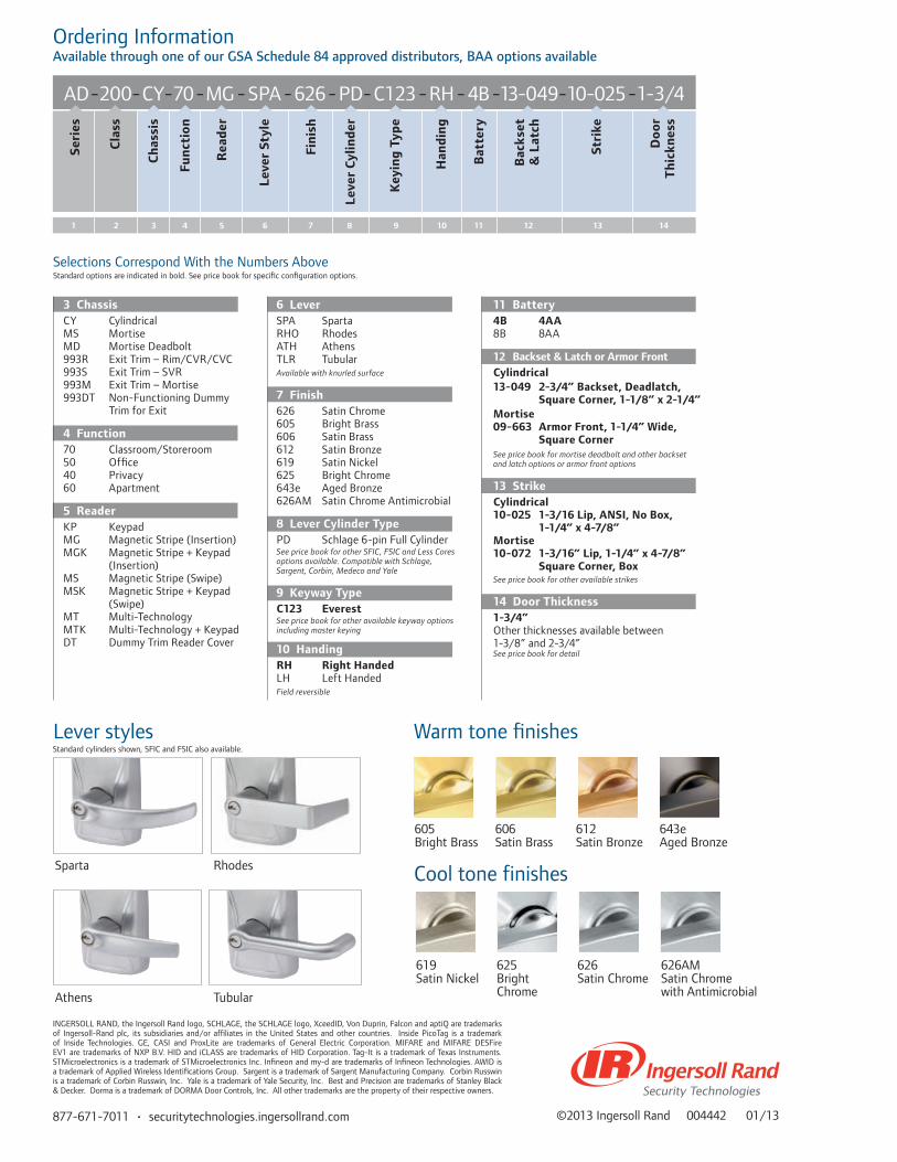
877-671-7011 • securitytechnologies.ingersollrand.com
Lever styles
Sparta Rhodes
Athens Tubular
Warm tone finishes
Cool tone finishes
605 606 612 643eBright Brass Satin Brass Satin Bronze Aged Bronze
619 625 626 626AMSatin Nickel Bright Satin Chrome Satin Chrome Chrome with Antimicrobial
AD-200-CY-70-MG - SPA-626-PD-C123 -RH - 4B-13-049-10-025-1-3/4Se
ries
Cla
ss
Ch
assi
s
Fun
ctio
n
Rea
der
Leve
r St
yle
Fin
ish
Leve
r C
ylin
der
Key
ing
Typ
e
Han
din
g
Bat
tery
Stri
ke
Doo
r T
hic
knes
s
Bac
kset
&
Lat
ch
3 41 2 5 6 7 8 9 10 11 12 13 14
©2013 Ingersoll Rand 004442 01/13
Selections Correspond With the Numbers AboveStandard options are indicated in bold. See price book for specific configuration options.
11 Battery4B 4AA8B 8AA
12 Backset & Latch or Armor FrontCylindrical13-049 2-3/4” Backset, Deadlatch,
Square Corner, 1-1/8” x 2-1/4” Mortise 09-663 Armor Front, 1-1/4” Wide,
Square CornerSee price book for mortise deadbolt and other backset and latch options or armor front options
13 StrikeCylindrical 10-025 1-3/16 Lip, ANSI, No Box, 1-1/4” x 4-7/8” Mortise 10-072 1-3/16” Lip, 1-1/4” x 4-7/8” Square Corner, Box See price book for other available strikes
14 Door Thickness1-3/4”Other thicknesses available between 1-3/8” and 2-3/4”See price book for detail
6 LeverSPA SpartaRHO RhodesATH AthensTLR TubularAvailable with knurled surface
7 Finish626 Satin Chrome605 Bright Brass606 Satin Brass612 Satin Bronze619 Satin Nickel625 Bright Chrome643e Aged Bronze626AM Satin Chrome Antimicrobial
8 Lever Cylinder TypePD Schlage 6-pin Full CylinderSee price book for other SFIC, FSIC and Less Cores options available. Compatible with Schlage, Sargent, Corbin, Medeco and Yale
9 Keyway TypeC123 EverestSee price book for other available keyway options including master keying
10 HandingRH Right Handed LH Left HandedField reversible
3 ChassisCY CylindricalMS MortiseMD Mortise Deadbolt993R Exit Trim – Rim/CVR/CVC993S Exit Trim – SVR993M Exit Trim – Mortise 993DT Non-Functioning Dummy
Trim for Exit
4 Function70 Classroom/Storeroom50 Office40 Privacy60 Apartment
5 ReaderKP KeypadMG Magnetic Stripe (Insertion)MGK Magnetic Stripe + Keypad
(Insertion)MS Magnetic Stripe (Swipe)MSK Magnetic Stripe + Keypad
(Swipe)MT Multi-TechnologyMTK Multi-Technology + KeypadDT Dummy Trim Reader Cover
Standard cylinders shown, SFIC and FSIC also available.
INGERSOLL RAND, the Ingersoll Rand logo, SCHLAGE, the SCHLAGE logo, XceedID, Von Duprin, Falcon and aptiQ are trademarks of Ingersoll-Rand plc, its subsidiaries and/or affiliates in the United States and other countries. Inside PicoTag is a trademark of Inside Technologies. GE, CASI and ProxLite are trademarks of General Electric Corporation. MIFARE and MIFARE DESFire EV1 are trademarks of NXP B.V. HID and iCLASS are trademarks of HID Corporation. Tag-It is a trademark of Texas Instruments. STMicroelectronics is a trademark of STMicroelectronics Inc. Infineon and my-d are trademarks of Infineon Technologies. AWID is a trademark of Applied Wireless Identifications Group. Sargent is a trademark of Sargent Manufacturing Company. Corbin Russwin is a trademark of Corbin Russwin, Inc. Yale is a trademark of Yale Security, Inc. Best and Precision are trademarks of Stanley Black & Decker. Dorma is a trademark of DORMA Door Controls, Inc. All other trademarks are the property of their respective owners.
Ordering InformationAvailable through one of our GSA Schedule 84 approved distributors, BAA options available

AD-Series electronic locks from Schlage are designed to be modular and provide more options to choose from, more functionality in the lock and more compatibility with existing systems. Its patent-pending modular design allows the lock to be customized to fit the needs of an application now, and can change to meet future needs without removing it from the door.
Factory orderable options include choices of magnetic stripe credential readers, chassis type, locking functions, power options, lever styles and finishes. It also offers a wide selection of features that can be configured in the field to customize your openings.
The AD-250 is a unique solution in which the credential, not the lock, carries access rights on a magnetic stripe card. This allows dynamic rights management on the card without reprogramming each lock in the facility. And the lock still maintains an audit trail of events at the door. This makes it a smart and economical solution for campus-like environments with a large number of users and offline openings.
On all AD-Series standalone locks, Schlage has built in many of the incremental features needed in a networked system such as request-to-exit and -enter sensors, interior cover tamper guard, as well as the door position switch. This way, if the customer chooses to network this opening in the future, all the components will be there to make the transition an easy one.
AD-250 Standalone Electronic Lock
Features and Benefits
• Security that’s more intelligent and convenient than traditional mechanical locking devices
• Audit trail reports that allow you to track usage• Update users and access rights using credentials instead
of having to visit each lock• The ability to upgrade to a networked solution without
removing the lock from the door• Available in cylindrical, mortise, mortise with deadbolt
and exit trim • Compatible with major brands of master key systems
and exit devices• Now available with Magnetic Swipe Reader• ANSI/BHMA A156.25, ANSI/BHMA Grade 1, UL 294,
UL10C, FCC Part 15, ADA, RoHS
Stan
dalo
ne L
ocki
ng S
olut
ions
AD
-250
Sta
ndal
one

Dimensions
Functions Classroom/Storeroom
Office
Privacy
Apartment
Note: Classroom/Storeroom and Office function not available with Mortise Deadbolt option. To ensure safety, all functions always allow for free egress.
Standard Status Signals Lock/Unlock Status
Mechanical Key Override
Battery Status
Schlage Utility Software on Handheld Device
The Schlage Utility Software (SUS) on the Handheld Device (HHD) provides an easy way to manage people, audits and locks for simple access control management.
Schlage Utility Software
• Initialize Lock and Accessories• Field Configure Devices
- Credential Reader Formats - Lock Function - Unlock Period - Failure Mode
- Audible Alarm ON/OFF• Service & Diagnostics
- Battery Status - Validate hardware and software revision
- Troubleshooting Status Signals• New device template simplifies configuration
HHD
• 3.5 in LCD display• Touch Screen/Keypad Backlit• 32-bit processor • OS: Windows Mobile 5.0• Memory: 128 MB RAM/256 MB ROM• Battery: Rechargeable 3.7 v,
1,230 mAH, Li-ion• Dimensions: 5.3” x 2.9” x 0.7”
(13.5 cm x 7.3 cm x 1.8 cm)• Weight: 0.42 lbs. (190 g)• 4 ft. (1.2 m) drop to steel surface,
2 drops per 6 sides
The HHD connects with AD-Series and CO-Series locks and accessories via the USB interface
HHD is also compatible with CM, CL, VIP, WA and KC2 Series locks via a serial cable connection.
AD-250 Electronic Lock Specifications
Users Unlimited, dependant on software
Audits Up to 10,000
Credential Verification Time ≤ 1 second
Visual/Audible Communications Tri-colored LED’s & audible indicators (field configurable)
System Interface Handheld Device
Power Supply 4AA, 8AA, 12 VDC or 24 VDC
Voltage Range 4 VDC to 26 VDC
Max Current Requirement Up to 250 mA
Battery Life Up to 2 yrs with 4AA
Operating Temperature - Exterior -31° to 151°F (-35° to 66°C)
Operating Temperature - Interior 32° to 120°F (0° to 49°C) (battery)
Operating Humidity 0 - 100% non-condensing
CertificationsANSI/BHMA A156.25, ANSI/BHMA Grade 1, UL 294, UL10 C, FCC Part 15, ADA, RoHS
Accessories Handheld Device (HHD), Magnetic Stripe Credential Encoder (CL-Encoder 2)
AD-Series Exit TrimThe AD-Series Exit Trim (installed with a universal mounting plate) is compatible with the following exit devices:
Von Duprin 98/99 & 98/99XP* Rim, Surface Vertical Rod, Mortise. Concealed Vertical Cable and Concealed Vertical Rod on metal doors only.
Von Duprin 22/22F* Rim, Surface Vertical Rod
Falcon 25* - Rim
Sargent® 80† Series - Rim
Precision™ 21 Rim 2100 converts to 21 with Precision's BP21 kit
Corbin Russwin® 5000Series - Rim
Yale® 7000 - Rim
Dorma® 9300 - Rim
* Request-to-Exit Switch optional for future network migration.
† Narrow design & reversible rim exits not compatible

Magnetic Stripe(Swipe)
Magnetic Stripe(Swipe)
+ KEYPAD
Cylindrical (Based on Schlage ND-Series) Mortise (Based on Schlage L-Series)
Mechanical Specifications
Handing
Chassis
Meets or exceeds A156.25 and A156.2 Series 4000, Grade 1 strength and operational requirements
2-3/4˝ standard, 2-3/8˝, 3-3/4˝ and 5˝ optional
1/2˝ throw security latch standard 3/4” throw optional
Pressure cast zinc, plated to match finish symbols
ANSI curved lip strike 1-1/4˝ x 4-7/8˝ x 1-3/16˝ lip to center standard, optional strikes, lip lengths and ANSI strike box available
Meets or exceeds A156.25 and A156.13 Series 1000, Grade 1 operational and security
2-3/4” only
Steel, plated to match finish symbols
ANSI curved lip strike 1-1/4” x 4-7/8” x 1-3/16” lip to center with dust box standard, optional strikes lip lengths available
ANSI Standard
Door Thickness
Backset
Latch Bolt
Levers
Strike
Cylinder & Keys
Handed to Order, Field Reversible
1-3/4” standard, 1-3/8” to 2-3/4” optional (available in 1/8” increments)
Schlage 6-pin Everest C123 keyway cylinder with two patented keys standard Additional options available including Standard, SFIC, FSIC and competitor brands
3/4” throw with anti-friction tongue standard 1” throw deadbolt on Mortise Deadbolt option*
Reader Specifications and Modules
• Triple Track Reader (1, 2 or 3), field configurable
• ABA, ISO76XX Standard• Reader can be cleaned without
removing lock from door• 12 button, 3x4 matrix
backlit keypad
• Triple Track Reader (1, 2 or 3), field configurable
• ABA, ISO76XX Standard
Magnetic Stripe(Insertion)
Magnetic Stripe(Insertion)
KEYPAD+
*Classroom/Storeroom and Office options not available with deadbolt.

877-671-7011 • securitytechnologies.ingersollrand.com
Selections Correspond With the Numbers Above
Lever styles
Sparta Rhodes
Athens Tubular
Warm tone finishes
Cool tone finishes
605 606 612 643eBright Brass Satin Brass Satin Bronze Aged Bronze
619 625 626 626AMSatin Nickel Bright Satin Chrome Satin Chrome Chrome with Antimicrobial
AD-250-CY-70-MG - SPA-626-PD-C123 -RH - 4B-13-049-10-025-1-3/4Se
ries
Cla
ss
Ch
assi
s
Fun
ctio
n
Rea
der
Leve
r St
yle
Fin
ish
Leve
r C
ylin
der
Key
ing
Typ
e
Han
din
g
Bat
tery
Stri
ke
Doo
r T
hic
knes
s
Bac
kset
&
Lat
ch
3 41 2 5 6 7 8 9 10 11 12 13 14
©2013 Ingersoll Rand 004436 01/13
Standard options are indicated in bold. See price book for specific configuration options.
11 Battery4B 4AA8B 8AA
12 Backset & Latch or Armor FrontCylindrical13-049 2-3/4” Backset, Deadlatch,
Square Corner, 1-1/8” x 2-1/4” Mortise 09-663 Armor Front, 1-1/4” Wide,
Square CornerSee price book for mortise deadbolt and other backset and latch options or armor front options
13 StrikeCylindrical 10-025 1-3/16 Lip, ANSI, No Box, 1-1/4” x 4-7/8” Mortise 10-072 1-3/16” Lip, 1-1/4” x 4-7/8” Square Corner, Box See price book for other available strikes
14 Door Thickness1-3/4”Other thicknesses available between 1-3/8” and 2-3/4 See price book for detail.
7 Finish626 Satin Chrome605 Bright Brass606 Satin Brass612 Satin Bronze619 Satin Nickel625 Bright Chrome643e Aged Bronze626AM Satin Chrome Antimicrobial
8 Lever Cylinder TypePD Schlage 6-pin Full CylinderSee price book for other SFIC, FSIC and Less Cores options available. Compatible with Schlage, Sargent, Corbin, Medeco and Yale
9 Keyway TypeC123 EverestSee price book for other available keyway options including master keying
10 HandingRH Right Handed LH Left HandedField reversible
3 ChassisCY CylindricalMS MortiseMD Mortise Deadbolt993R Exit Trim – Rim/CVR/CVC993S Exit Trim – SVR993M Exit Trim – Mortise993DT Non-Functioning Dummy
Trim for Exit
4 Function70 Classroom/Storeroom50 Office40 Privacy60 Apartment
5 ReaderMG Magnetic Stripe (Insertion)MGK Magnetic Stripe + Keypad
(Insertion)MS Magnetic Stripe (Swipe)MSK Magnetic Stripe + Keypad
(Swipe)DT Dummy Trim
6 LeverSPA SpartaRHO RhodesATH AthensTLR TubularAvailable with knurled surface
Standard cylinders shown, SFIC and FSIC also available.
Ordering InformationAvailable through one of our GSA Schedule 84 approved distributors, BAA options available
INGERSOLL RAND, the Ingersoll Rand logo, SCHLAGE, the SCHLAGE logo, Von Duprin and Falcon are trademarks of Ingersoll-Rand plc, its subsidiaries and/or affiliates in the United States and other countries. Sargent is a trademark of Sargent Manufacturing Company. Corbin Russwin is a trademark of Corbin Russwin, Inc. Yale is a trademark of Yale Security, Inc. Best and Precision are trademarks of Stanley Black & Decker. Dorma is a trademark of DORMA Door Controls, Inc. All other trademarks are the property of their respective owners.

OverviewThe AD-Series Electronic Lock is available in 993 Exit Trim for use on openings that require exit devices for either retrofit or new construction applications. Offline and networked solutions are available.
The 993 Exit Trim was designed to suite with AD-Series cylindrical and mortise locksets to ensure that the facility remains aesthetically consistent.
The AD-Series 993 Exit Trim utilizes universal hardware to simplify installation of offline trim to a variety of exit devices, including Rim style from Von Duprin, Falcon, Sargent®, Precision™ Corbin Russwin®, Dorma®, and Yale®.
Available Exit Trim Styles:• 993R – Rim, Concealed Vertical Cable or Concealed Vertical Rod
(CVC and CVR for metal doors only)• 993S – Surface Vertical Rod• 993M – Mortise
* For metal doors only † Narrow design & reversible rim exits not compatible
The proper low current request to exit switch (RX-LC) is required for AD-300/301 and AD-400/401.
Part Numbers for Request to Exit Switch:• Von Duprin: 050281• Falcon: 650359
AD-Series Exit Trim Compatibility
Features and Benefits
• Multiple Credential Reader Options • Offline and Networked Communication Options • A wide variety of finishes and lever styles• Power options that include hardwired (12 VDC or 24
VDC) or batteries (4AA or 8AA)• Compatible with most Standard, FSIC or SFIC keyways
from major brands of master key systems including Schlage, Sargent®, Corbin®, Medeco® and Yale®
CompatibilityDevices AD-200/250 AD-300/301 AD-400/401
Von Duprin 98/99 and 98/99XP Rim/SVR/CVR*/CVC*/Mortise
X X X
Von Duprin 22/22F Rim/SVR X X X
Falcon 25 Rim X X X
Sargent® 80† Rim X
Precision™ 21 Rim (2100 converts to 21 with Precision’s BP21 kit)
X
Yale® 7000 Rim X
Corbin Russwin® 5000 Rim X
Dorma® 9300 Rim X
Stan
dalo
ne L
ocki
ng S
olut
ions
AD
-Ser
ies
Exit
Trim

877-671-7011 • securitytechnologies.ingersollrand.com ©2013 Ingersoll Rand 004382 01/13
DIMENSIONS
Exterior View
AD-Series - 993 Exit Trim
Interior View
AD-200/250/300*/301* - all styles
Interior View
AD-400/401 all styles
Side View
AD-200/250/300*/ 301* - RIM/CVR/CVC or Mortise
Side View
AD-400/401 RIM/CVR/CVC or Mortise
Side View
AD-200/250/300*/ 301* SVR
Side View
AD-400/401 SVR
Available AD-Series Reader Modules
• Multi-Technology (125 kHz proximity and 13.56 MHz smart card)
• FIPS 201-1 Compliant Multi-Technology (125 kHz proximity and 13.56 MHz smart card) sold complete with AD-301 and AD-401 only
• Magnetic Stripe • Keypad Only • All credential readers available + Keypad * unlike other AD-Series chassis styles,
upgrading reader modules on the 993 Exit Trim requires the exterior escutcheon to be removed from the door
Available Communication Options
• AD-400: Networked Wireless Locks• AD-401: Networked Wireless Locks -
FIPS 201-1 compliant • AD-300: Networked Hardwired Locks• AD-301: Networked Hardwired Locks -
FIPS 201-1 compliant • AD-250: Offline, access rights stored
on the magnetic stripe credential• AD-200: Offline, access rights stored
on the lockProfile View
* AD-300/301 includes LED indicatorNote: (2) #7 fasteners with decorative washers located 11.88” below bottom edge of lockINGERSOLL RAND, the Ingersoll Rand logo, SCHLAGE, the SCHLAGE logo, Von Duprin and Falcon are trademarks of Ingersoll-Rand plc, its subsidiaries and/or affiliates in the United States and other countries. Sargent is a trademark of Sargent Manufacturing Company. Precision is a trademark of Stanley Black & Decker. Yale is a trademark of Tale Security, Inc. Corbin Russwin is a trademark of Corbin Russwin, Inc. Dorma is a trademark of DORMA Door Controls, Inc. All other trademarks are the property of their respective owners.

The CO-Series is the ideal solution for customers seeking the added security and convenience of electronic access control without the cost or complexity of a fully networked system.
The CO-100 is a standalone lock that is manually programmable. User rights for the CO-100 are stored on the lock. Unique PIN codes can be assigned to each user. This minimizes the number of mechanical keys issued which protects the integrity of your key system. PIN codes can be easily added or deleted at anytime right at the door.
The CO-100 from Schlage offers you many choices. Cylindrical, mortise, and exit trim chassis options are available as well as a wide variety of finishes and levers to suite with your existing hardware.
Mechanical key override is standard and compatible with multiple cylinder types. The CO-Series is also compatible with many popular brands of exit devices.
The CO-Series has been tested the highest standards in the industry to ensure quality and reliability you have come to expect from Schlage. The CO-Series is ANSI/BHMA A156.25, ANSI/BHMA Grade 1 certified and UL 294 listed.
CO-100 Standalone Electronic Lock
Features and Benefits
• Manually Programmable• Up to 500 unique 3-6 digit PIN codes stored on the
lock• ANSI/BHMA A156.25, ANSI/BHMA Grade 1 certified
and UL 294 listed• Classroom/Storeroom function and Office function
available• Chassis options include cylindrical, mortise, and exit
trim• Compatible with most major brands of key systems and
exit devices• Normal, toggle, pass through, and freeze credential
attributes available
Images shown are not to scale.
Stan
dalo
ne L
ocki
ng S
olut
ions
CO-1
00 S
tand
alon
e

Dimensions
Functions Classroom/Storeroom
Office
Standard Status Signals Battery Status - indicated
by blinking lights
Specifications
Manually Programmable Options
Programming*
Normal Use*
Toggle*
Freeze*
Pass-through*
Used to enable programming of the lock. Does not unlock the lock.
Unlocks the lock momentarily when in a normally secured state.
Changes the state of the lock unless in Freeze state.
Maintains the lock in current state until Freeze PIN is entered again.
Unlocks a lock momentarily, regardless of state.
*Credentials can be 3-6 digits in length.
Credential Type Function
Exterior of the Lock Interior of the LockCylindrical Mortise
CO-100 Electronic Lock Specifications
Users 500
Credential Verification Time (Keypad Only)
≤ 1 second
Visual/Audible Communications Tri-colored LED’s & audible indicators
Power Supply 4 AA batteries (standard off the shelf: included)
Battery Life Up to 2 yrs with 4 AA batteries
Operating Temperature - Exterior -31° to 151°F (-35° to 66°C)
Operating Temperature - Interior 32° to 120°F (0° to 49°C) due to battery
Operating Humidity 0 - 100% non-condensing
Certifications ANSI/BHMA A156.25, ANSI/BHMA Grade 1, UL 294, UL 10 C, FCC Part 15, ADA and RoHS

Mechanical Specifications
Handing
Meets or exceeds A156.25 and A156.2 Series 4000, Grade 1 strength and operational requirements
2-3/4˝ standard, 2-3/8˝, 3-3/4˝ and 5˝ optional
1/2˝ throw security latch standard 3/4” throw optional
Pressure cast zinc, plated to match finish symbols
ANSI curved lip strike 1-1/4˝ x 4-7/8˝ x 1-3/16˝ lip to center standard, optional strikes, lip lengths and ANSI strike box available
Meets or exceeds A156.25 and A156.13 Series 1000, Grade 1 operational and security
2-3/4” only
Steel, plated to match finish symbols
ANSI curved lip strike 1-1/4” x 4-7/8” x 1-3/16” lip to center with dust box standard, optional strikes lip lengths available
ANSI Standard
Door Thickness
Backset
Latch Bolt
Levers
Strike
Handed to Order, Field Reversible
1-3/4” standard, 1-3/8” to 2-3/4” optional (available in 1/8” increments)
3/4” throw with anti-friction tongue standard
Chassis Cylindrical (Based on Schlage ND-Series) Mortise (Based on Schlage L-Series)
Compatibility
Full Cylinder Full Size Interchangeable Core
Small Format Interchangeable Core
Cylinder Compatibility Full Sizekey-in-lever 6 pin
Full Sizekey-in-lever 7 pin
FSIC6 & 7pin
SFIC6 & 7pin
Schlage Falcon Sargent® (10L + 11L Full Size) Corbin Russwin® Yale® (also includes Medeco 31*0100 FSIC)
Best®
= with cylinder or less cylinder options = less cylinder only= less cylinder, only with Sparta and Rhodes levers Note: See pricebook for specific configurations.
Exit Device Compatibility Rim SVR CVR/CVC Mortise
Von Duprin 98/99 and 98/99 XP ✓ ✓ ✓* ✓
Von Duprin 22/22F ✓ ✓
Falcon 25 ✓
Corbin Russwin® 5000 ✓Precision™ 21 Rim 2100 converts to 21 with Precision's BP21 kit ✓
Yale® 7000 ✓
Dorma® 9300 ✓
Sargent® 80† ✓
* Metal door only† Narrow design & reversible rim exits not compatible
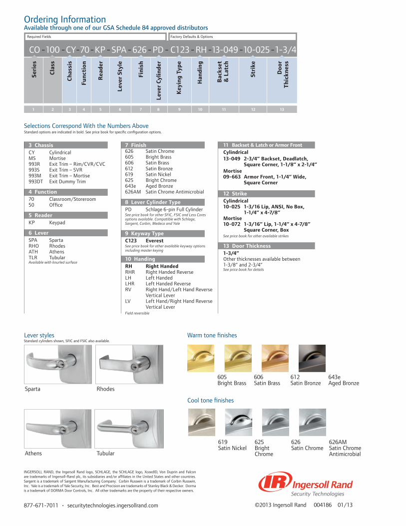
877-671-7011 • securitytechnologies.ingersollrand.com
CO -100 -CY-70-KP - SPA-626-PD - C123 -RH -13-049 -10-025-1-3/4
Seri
es
Cla
ss
Ch
assi
s
Fun
ctio
n
Rea
der
Leve
r St
yle
Fin
ish
Leve
r C
ylin
der
Key
ing
Typ
e
Han
din
g
3 41 2 5 6 7 8 9 10
Selections Correspond With the Numbers AboveStandard options are indicated in bold. See price book for specific configuration options.
11 Backset & Latch or Armor FrontCylindrical13-049 2-3/4” Backset, Deadlatch,
Square Corner, 1-1/8” x 2-1/4” Mortise 09-663 Armor Front, 1-1/4” Wide,
Square Corner
12 StrikeCylindrical 10-025 1-3/16 Lip, ANSI, No Box, 1-1/4” x 4-7/8” Mortise 10-072 1-3/16” Lip, 1-1/4” x 4-7/8” Square Corner, Box See price book for other available strikes
13 Door Thickness1-3/4”Other thicknesses available between 1-3/8” and 2-3/4”See price book for details
7 Finish626 Satin Chrome605 Bright Brass606 Satin Brass612 Satin Bronze619 Satin Nickel625 Bright Chrome643e Aged Bronze626AM Satin Chrome Antimicrobial
8 Lever Cylinder TypePD Schlage 6-pin Full CylinderSee price book for other SFIC, FSIC and Less Cores options available. Compatible with Schlage, Sargent, Corbin, Medeco and Yale
9 Keyway TypeC123 Everest See price book for other available keyway options including master keying
10 HandingRH Right Handed RHR Right Handed ReverseLH Left HandedLHR Left Handed ReverseRV Right Hand/Left Hand Reverse Vertical LeverLV Left Hand/Right Hand Reverse Vertical Lever Field reversible
3 ChassisCY CylindricalMS Mortise993R Exit Trim – Rim/CVR/CVC993S Exit Trim – SVR993M Exit Trim – Mortise993DT Exit Dummy Trim
4 Function70 Classroom/Storeroom50 Office
5 ReaderKP Keypad
6 LeverSPA SpartaRHO RhodesATH AthensTLR TubularAvailable with knurled surface
Stri
ke
Doo
r T
hic
knes
s
Bac
kset
&
Lat
ch
11 12 13
©2013 Ingersoll Rand 004186 01/13
Lever styles
Sparta Rhodes
Athens Tubular
Warm tone finishes
Cool tone finishes
605 606 612 643eBright Brass Satin Brass Satin Bronze Aged Bronze
619 625 626 626AMSatin Nickel Bright Satin Chrome Satin Chrome Chrome Antimicrobial
Standard cylinders shown, SFIC and FSIC also available.
Ordering InformationAvailable through one of our GSA Schedule 84 approved distributors
Required Fields Factory Defaults & Options
INGERSOLL RAND, the Ingersoll Rand logo, SCHLAGE, the SCHLAGE logo, XceedID, Von Duprin and Falcon are trademarks of Ingersoll-Rand plc, its subsidiaries and/or affiliates in the United States and other countries. Sargent is a trademark of Sargent Manufacturing Company. Corbin Russwin is a trademark of Corbin Russwin, Inc. Yale is a trademark of Yale Security, Inc. Best and Precision are trademarks of Stanley Black & Decker. Dorma is a trademark of DORMA Door Controls, Inc. All other trademarks are the property of their respective owners.
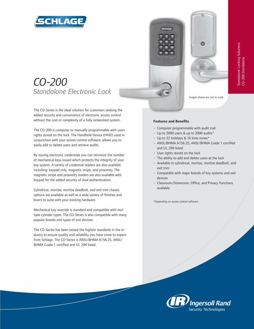
The CO-Series is the ideal solution for customers seeking the added security and convenience of electronic access control without the cost or complexity of a fully networked system.
The CO-200 is computer or manually programmable with users rights stored on the lock. The Handheld Device (HHD) used in conjunction with your access control software, allows you to easily add or delete users and retrieve audits.
By issuing electronic credentials you can minimize the number of mechanical keys issued which protects the integrity of your key system. A variety of credential readers are also available including: keypad only, magnetic stripe, and proximity. The magnetic stripe and proximity readers are also available with keypad for the added security of dual authentication.
Cylindrical, mortise, mortise deadbolt, and exit trim chassis options are available as well as a wide variety of finishes and levers to suite with your existing hardware.
Mechanical key override is standard and compatible with mul-tiple cylinder types. The CO-Series is also compatible with many popular brands and types of exit devices.
The CO-Series has been tested the highest standards in the in-dustry to ensure quality and reliability you have come to expect from Schlage. The CO-Series is ANSI/BHMA A156.25, ANSI/BHMA Grade 1 certified and UL 294 listed.
CO-200 Standalone Electronic Lock
Features and Benefits
• Computer programmable with audit trail• Up to 2000 users & up to 2000 audits*• Up to 32 holidays & 16 time zones*• ANSI/BHMA A156.25, ANSI/BHMA Grade 1 certified
and UL 294 listed• User rights stored on the lock• The ability to add and delete users at the lock• Available in cylindrical, mortise, mortise deadbolt, and
exit trim• Compatible with major brands of key systems and exit
devices• Classroom/Storeroom, Office, and Privacy functions
available
*Depending on access control software.
Images shown are not to scale.
Stan
dalo
ne L
ocki
ng S
olut
ions
CO-2
00 S
tand
alon
e

Schlage Utility Software on Handheld Device
The Schlage Utility Software (SUS) on the Handheld Device (HHD), in conjunction with your access control software, provides an easy way to manage people, audits and locks for simple access control management.
Schlage Utility Software
• Initialize Lock and Accessories• Field Configure Devices
- Credential Reader Formats - Lock Function - Unlock Period - Failure Mode
- Audible Alarm ON/OFF• Service & Diagnostics
- Battery Status - Validate hardware and software revision - Troubleshooting Status Signals
• New device template simplifies configuration
HHD
• 3.5 in LCD display• Touch Screen/Keypad Backlit• 32-bit processor • OS: Windows Mobile 5.0• Memory: 128 MB RAM/256 MB ROM• Battery: Rechargeable 3.7 v,
1,230 mAH, Li-ion• Dimensions: 5.3” x 2.9” x 0.7”
(13.5 cm x 7.3 cm x 1.8 cm)• Weight: 0.42 lbs. (190 g)• 4 ft. (1.2 m) drop to steel surface,
2 drops per 6 sidesThe HHD connects with CO-Series and AD-Series locks and accessories via the USB interface
Functions Classroom/Storeroom
Office
Privacy*
Note: Classroom/Storeroom and Office function not available with Mortise Deadbolt option. To ensure safety, all functions always allow for free egress.
Standard Status Signals Mechanical Key Override
Battery Status - indicated by blinking lights
Specifications
HHD is also compatible with CM, CL, VIP, WA, and KC2 series locks via a serial cable connection.
*Door position switch is required for cylindrical and mortise chassis with privacy function.
*Depending on access control software.
Dimensions
Exterior of the LockInterior of the LockCylindrical
Mortise Deadbolt
CO-200 Electronic Lock Specifications
Users Up to 2,000*
Audits Up to 2,000*
Credential Verification Time ≤ 1 second
Visual/Audible Communications Tri-colored LED’s & audible indicators
Power Supply 4 AA batteries (standard off the shelf: included)
Voltage Range 4 VDC to 7 VDC
Max Current Requirement Up to 250 mA
Battery Life Up to 2 yrs with 4 AA batteries
Operating Temperature - Exterior -31° to 151°F (-35° to 66°C)
Operating Temperature - Interior 32° to 120°F (0° to 49°C) due to batteries
Operating Humidity 0 - 100% non- condensing
CertificationsANSI/BHMA A156.25, ANSI/BHMA Grade 1, UL 294, UL 10 C, FCC Part 15, ADA and RoHS

• Proximity• Proximity• Keypad • Magnetic Stripe • Magnetic Stripe
Available CO-200 Reader Options
Full Cylinder Full Size Interchangeable Core
Small Format Interchangeable Core
Cylinder Compatibility Full Sizekey-in-lever 6 pin
Full Sizekey-in-lever 7 pin
FSIC6 & 7pin
SFIC6 & 7pin
Schlage Falcon Sargent® (10L + 11L Full Size) Corbin Russwin® Yale® (also includes Medeco 31*0100 FSIC)
Best®
= with cylinder or less cylinder options = less cylinder only= less cylinder, only with Sparta and Rhodes levers Note: See pricebook for specific configurations.
KEYPAD+ KEYPAD+
Mechanical Specifications
Chassis Cylindrical (Based on Schlage ND-Series) Mortise (Based on Schlage L-Series)
Handing Handed to Order, Field Reversible
ANSI Standard Meets or exceeds A156.25 and A156.2 Series 4000, Grade 1 strength and operational requirements
Meets or exceeds A156.25 and A156.13 Series 1000, Grade 1 operational and security
Door Thickness 1-3/4” standard, 1-3/8” to 2-3/4” optional (available in 1/8” increments)
Backset 2-3/4˝ standard, 2-3/8˝, 3-3/4˝ and 5˝ optional 2-3/4” only
Latch Bolt 1/2˝ throw security latch standard 3/4” throw optional
3/4” throw with anti-friction tongue standard 1” throw deadbolt on Mortise Deadbolt option
Levers Pressure cast zinc, plated to match finish symbols Steel, plated to match finish symbols
StrikeANSI curved lip strike 1-1/4˝ x 4-7/8˝ x 1-3/16˝ lip to center standard, optional strikes, lip lengths and ANSI strike box available
ANSI curved lip strike 1-1/4” x 4-7/8” x 1-3/16” lip to center with dust box standard, optional strikes lip lengths available
Reader Specifications
Keypad Magnetic Stripe Proximity
Frequency Standards N/A
ABA, ISO76XX Standard High & Low Coercivity
125 kHz
Maximum Read Range N/A N/A (Swipe card) up to 1.25”
Compatibility 3-6 digit pin codeTriple Track Reader (1, 2 or 3), field configurable
Schlage, XceedID®, HID®, GE/CASI ProxLite™ and AWID®
Compatible XceedID/Schlage Credentials
N/AConfigurable to read complete track 1, 2 or 3
125 kHz Clamshell, ISO Card, ISO Card with Magnetic Stripe, Keyfob, and PVC Disk (7000 Series)
Style/Layout 12-button, 3x4 matrixOption for 12-button, 3x4 matrix
Option for 12-button, 3x4 matrix
The combo proximity keyfobs with iButton® option are available which allows you to manage proximity and iButton® technologies in the same facility.

877-671-7011 • securitytechnologies.ingersollrand.com
CO-200-CY-70 - PR- SPA-626-PD-C123 -RH -13-049-10-025-1-3/4
Seri
es
Cla
ss
Ch
assi
s
Fun
ctio
n
Rea
der
Leve
r St
yle
Fin
ish
Leve
r C
ylin
der
Key
ing
Typ
e
Han
din
g
Stri
ke
Doo
r T
hic
knes
s
Bac
kset
&
Lat
ch
3 41 2 5 6 7 8 9 10 11 12 13
©2013 Ingersoll Rand 004185 01/13
Selections Correspond With the Numbers AboveStandard options are indicated in bold. See price book for specific configuration options.
11 Backset & Latch or Armor FrontCylindrical13-049 2-3/4” Backset, Deadlatch,
Square Corner, 1-1/8” x 2-1/4” Mortise 09-663 Armor Front, 1-1/4” Wide,
Square CornerSee price book for mortise deadbolt and other backset and latch options or armor front options
12 StrikeCylindrical 10-025 1-3/16 Lip, ANSI, No Box, 1-1/4” x 4-7/8” Mortise 10-072 1-3/16” Lip, 1-1/4” x 4-7/8” Square Corner, Box See price book for other available strikes
13 Door Thickness1-3/4”Other thicknesses available between 1-3/8” and 2-3/4”See price book for detail
7 Finish626 Satin Chrome605 Bright Brass606 Satin Brass612 Satin Bronze619 Satin Nickel625 Bright Chrome643e Aged Bronze626AM Satin Chrome Antimicrobial
8 Lever Cylinder TypePD Schlage 6-pin Full CylinderSee price book for other SFIC, FSIC and Less Cores options available. Compatible with Schlage, Sargent, Corbin, Medeco and Yale
9 Keyway TypeC123 EverestSee price book for other available keyway options including master keying
10 HandingRH Right Handed RHR Right Handed ReverseLH Left HandedLHR Left Handed ReverseRV Right Hand/Left Hand Reverse Vertical LeverLV Left Hand/Right Hand Reverse Vertical LeverField reversible
3 ChassisCY CylindricalMS MortiseMD Mortise Deadbolt993R Exit Trim – Rim/CVR/CVC993S Exit Trim – SVR993M Exit Trim – Mortise 993DT Exit Dummy Trim
4 Function70 Classroom/Storeroom50 Office40 Privacy
5 ReaderKP KeypadMS Magnetic StripeMSK Magnetic Stripe + KeypadPR ProximityPRK Proximity + Keypad
6 LeverSPA SpartaRHO RhodesATH AthensTLR TubularAvailable with knurled surface
605 606 612 643eBright Brass Satin Brass Satin Bronze Aged Bronze
619 625 626 626AMSatin Nickel Bright Satin Chrome Satin Chrome Chrome Antimicrobial
Standard cylinders shown, SFIC and FSIC also available.Lever styles Warm tone finishes
Cool tone finishes
Sparta Rhodes
Athens Tubular
Ordering InformationAvailable through one of our GSA Schedule 84 approved distributors
Required Fields Factory Defaults & Options
INGERSOLL RAND, the Ingersoll Rand logo, SCHLAGE, the SCHLAGE logo, XceedID, Von Duprin and Falcon are trademarks of Ingersoll-Rand plc, its subsidiaries and/or affiliates in the United States and other countries. Sargent is a trademark of Sargent Manufacturing Company. Corbin Russwin is a trademark of Corbin Russwin, Inc. Yale is a trademark of Yale Security, Inc. Best and Precision are trademarks of Stanley Black & Decker. Dorma is a trademark of DORMA Door Controls, Inc. All other trademarks are the property of their respective owners.

The CO-Series is the ideal solution for customers seeking the added security and convenience of electronic access control without the cost or complexity of a fully networked system.
The CO-250 is a computer programmable offline lock that stores user rights on the magnetic stripe credential, and captures an audit trail in the lock. The CO-250 provides dynamic rights management, meaning you do not have to visit the door to change user access rights. This makes it a cost effective solution for offline environments with a large number of users. The CO-250 also allows you to retrieve audits by using the Handheld Device (HHD) in conjunction with your access control software.
The CO-250 from Schlage offers you many choices. Cylindrical, mortise, mortise deadbolt, and exit trim chassis options are available as well as a wide variety of finishes and levers to suite with your existing hardware.
Mechanical key override is standard and compatible with multiple cylinder types. The CO-Series is also compatible with many popular brands of exit devices.
The CO-Series has been tested the highest standards in the industry to ensure quality and reliability you have come to expect from Schlage. The CO-Series is ANSI/BHMA A156.25, ANSI/BHMA Grade 1 certified and UL 294 listed.
CO-250 Standalone Electronic Lock
Features and Benefits• Computer programmable with audit trail• Unlimited number of users and up
to 4000 audits*• Available with Magnetic Stripe and Magnetic Stripe
plus Keypad• Up to 32 holidays & 16 time zones*• ANSI/BHMA A156.25, ANSI/BHMA Grade 1 certified
and UL 294 listed• User rights stored on the magnetic stripe credential• The ability to easily add and delete users • Available in cylindrical, mortise, mortise deadbolt, and
exit trim• Compatible with major brands of key systems and exit
devices• Classroom/Storeroom, Office, and Privacy functions
available
*Depending on access control software.
Images shown are not to scale.
Stan
dalo
ne L
ocki
ng S
olut
ions
CO-2
50 S
tand
alon
e

Dimensions
Schlage Utility Software on Handheld Device
The Schlage Utility Software (SUS) on the Handheld Device (HHD), in conjunction with your access control software, provides an easy way to manage people, audits and locks for simple access control management.
Schlage Utility Software
• Initialize Lock and Accessories• Field Configure Devices
- Credential Reader Formats - Lock Function - Unlock Period - Failure Mode
- Audible Alarm ON/OFF• Service & Diagnostics
- Battery Status - Validate hardware and software revision - Troubleshooting Status Signals
• New device template simplifies configuration
HHD
• 3.5 in LCD display• Touch Screen/Keypad Backlit• 32-bit processor • OS: Windows Mobile 5.0• Memory: 128 MB RAM/256 MB ROM• Battery: Rechargeable 3.7 v,
1,230 mAH, Li-ion• Dimensions: 5.3” x 2.9” x 0.7”
(13.5 cm x 7.3 cm x 1.8 cm)• Weight: 0.42 lbs. (190 g)• 4 ft. (1.2 m) drop to steel surface,
2 drops per 6 sidesThe HHD connects with CO-Series and AD-Series locks and accessories via the USB interface
Specifications
HHD is also compatible with CM, CL, VIP, WA, and KC2 series locks via a serial cable connection.
Functions Classroom/Storeroom
Office
Privacy* Note: Classroom/Storeroom and Office function not available with Mortise Deadbolt option. To ensure safety, all functions always allow for free egress.
Standard Status Signals Mechanical Key Override
Battery Status
*Door position switch is required for cylindrical and mortise chassis with privacy function.
Exterior of the LockInterior of the LockCylindrical
Mortise Deadbolt
*Depending on access control software.
CO-250 Electronic Lock Specifications
Users Unlimited*
Audits Up to 4,000*
Credential Verification Time ≤ 1 second
Visual/Audible Communications Tri-colored LED’s & audible indicators
System Interface Handheld Device
Power Supply 4 AA batteries
Battery Life Up to 2 yrs with 4 AA batteries
Operating Temperature - Exterior -31° to 151°F (-35° to 66°C)
Operating Temperature - Interior 32° to 120°F (0° to 49°C) due to batteries
Operating Humidity 0 - 100% non-condensing
Certifications ANSI/BHMA A156.25, ANSI/BHMA Grade 1, UL 294, UL 10 C, FCC Part 15, ADA and ROHS
Accessories Handheld Device (HHD), Magnetic Stripe Credential Encoder (CL-Encoder 2)

• Triple Track Reader (1, 2 or 3), field configurable
• ABA, ISO76XX Standard• 12 button, 3x4 matrix keypad
• Triple Track Reader (1, 2 or 3), field configurable
• ABA, ISO76XX Standard
Magnetic Stripe Magnetic Stripe
Reader Specifications
Compatibility
Full Cylinder Full Size Interchangeable Core
Small Format Interchangeable Core
Cylinder Compatibility Full Sizekey-in-lever 6 pin
Full Sizekey-in-lever 7 pin
FSIC6 & 7pin
SFIC6 & 7pin
Schlage Falcon Sargent® (10L + 11L Full Size) Corbin Russwin® Yale® (includes Medeco 31*0100 FSIC) Best®
= with cylinder or less cylinder options = less cylinder only= less cylinder, only with Sparta and Rhodes levers Note: See pricebook for specific configurations.
Mechanical Specifications
Chassis Cylindrical (Based on Schlage ND-Series) Mortise (Based on Schlage L-Series)
Handing Handed to Order, Field Reversible
ANSI Standard Meets or exceeds A156.25 and A156.2 Series 4000, Grade 1 strength and operational requirements
Meets or exceeds A156.25 and A156.13 Series 1000, Grade 1 operational and security
Door Thickness 1-3/4” standard, 1-3/8” to 2-3/4” optional (available in 1/8” increments)
Backset 2-3/4˝ standard, 2-3/8˝, 3-3/4˝ and 5˝ optional 2-3/4” only
Latch Bolt 1/2˝ throw security latch standard 3/4” throw optional
3/4” throw with anti-friction tongue standard 1” throw deadbolt on Mortise Deadbolt option
Levers Pressure cast zinc, plated to match finish symbols Steel, plated to match finish symbols
StrikeANSI curved lip strike 1-1/4˝ x 4-7/8˝ x 1-3/16˝ lip to center standard, optional strikes, lip lengths and ANSI strike box available
ANSI curved lip strike 1-1/4” x 4-7/8” x 1-3/16” lip to center with dust box standard, optional strikes lip lengths available
KEYPAD+
Exit Device Compatibility Rim SVR CVR/CVC Mortise
Von Duprin 98/99 and 98/99 XP ✓ ✓ ✓* ✓
Von Duprin 22/22F ✓ ✓
Falcon 25 ✓
Corbin Russwin® 5000 ✓Precision™ 21 Rim 2100 converts to 21 with Precision's BP21 kit ✓
Yale® 7000 ✓
Dorma® 9300 ✓
Sargent® 80† ✓* Metal door only† Narrow design & reversible rim exits not compatible

877-671-7011 • securitytechnologies.ingersollrand.com
Selections Correspond With the Numbers Above
CO-250-CY-70- MS - SPA-626-PD-C123 -RH -13-049-10-025-1-3/4
Seri
es
Cla
ss
Ch
assi
s
Fun
ctio
n
Rea
der
Leve
r St
yle
Fin
ish
Leve
r C
ylin
der
Key
ing
Typ
e
Han
din
g
Stri
ke
Doo
r T
hic
knes
s
Bac
kset
&
Lat
ch
3 41 2 5 6 7 8 9 10 11 12 13
Standard options are indicated in bold. See price book for specific configuration options.
11 Backset & Latch or Armor FrontCylindrical13-049 2-3/4” Backset, Deadlatch,
Square Corner, 1-1/8” x 2-1/4” Mortise 09-663 Armor Front, 1-1/4” Wide,
Square CornerSee price book for mortise deadbolt and other backset and latch options or armor front options
12 StrikeCylindrical 10-025 1-3/16 Lip, ANSI, No Box, 1-1/4” x 4-7/8” Mortise 10-072 1-3/16” Lip, 1-1/4” x 4-7/8” Square Corner, Box See price book for other available strikes
13 Door Thickness1-3/4”Other thicknesses available between 1-3/8” and 2-3/4 See price book for detail.
7 Finish626 Satin Chrome605 Bright Brass606 Satin Brass612 Satin Bronze619 Satin Nickel625 Bright Chrome643e Aged Bronze626AM Satin Chrome Antimicrobial
8 Lever Cylinder TypePD Schlage 6-pin Full CylinderSee price book for other SFIC, FSIC and Less Cores options available. Compatible with Schlage, Sargent, Corbin, Medeco and Yale
9 Keyway TypeC123 EverestSee price book for other available keyway options including master keying
10 HandingRH Right Handed RHR Right Handed ReverseLH Left HandedLHR Left Handed ReverseRV Right Hand/Left Hand Reverse Vertical LeverLV Left Hand/Right Hand Reverse Vertical LeverField reversible
3 ChassisCY CylindricalMS MortiseMD Mortise Deadbolt993R Exit Trim – Rim/CVR/CVC993S Exit Trim – SVR993M Exit Trim – Mortise993DT Exit Dummy Trim
4 Function70 Classroom/Storeroom50 Office40 Privacy
5 ReaderMS Magnetic StripeMSK Magnetic Stripe + Keypad
6 LeverSPA SpartaRHO RhodesATH AthensTLR TubularAvailable with knurled surface
©2013 Ingersoll Rand 004184 01/13
605 606 612 643eBright Brass Satin Brass Satin Bronze Aged Bronze
619 625 626 626AMSatin Nickel Bright Satin Chrome Satin Chrome Chrome Antimicrobial
Standard cylinders shown, SFIC and FSIC also available.Lever styles Warm tone finishes
Cool tone finishes
Sparta Rhodes
Athens Tubular
Ordering InformationAvailable through one of our GSA Schedule 84 approved distributors
Required Fields Factory Defaults & Options
INGERSOLL RAND, the Ingersoll Rand logo, SCHLAGE, the SCHLAGE logo, XceedID, Von Duprin and Falcon are trademarks of Ingersoll-Rand plc, its subsidiaries and/or affiliates in the United States and other countries. Sargent is a trademark of Sargent Manufacturing Company. Corbin Russwin is a trademark of Corbin Russwin, Inc. Yale is a trademark of Yale Security, Inc. Best and Precision are trademarks of Stanley Black & Decker. Dorma is a trademark of DORMA Door Controls, Inc. All other trademarks are the property of their respective owners.

The CO-Series offers 993 exit trim for use with compatible exit devices in retrofit or new construction applications.
The 993 Exit Trim was designed to suite with CO-Series cylindrical and mortise locksets to ensure that the facility remains aesthetically consistent.
The CO-Series 993 Exit Trim utilizes universal hardware to simplify installation of offline trim to a variety of exit devices, including Rim style from Von Duprin, Falcon, Sargent®, Corbin Russwin®, Dorma®, and Yale®.
Available Exit Trim Styles:• 993R – Rim, Concealed Vertical Rod or Concealed Vertical
Cable (CVR/CVC for metal doors only)• 993S – Surface Vertical Rod• 993M – Mortise• 993DT – Non-Functioning Dummy Trim for Exit
CO-Series Exit Trim Compatibility
Features and Benefits
• Multiple Credential Reader Options • A wide variety of finishes and lever styles• Powered by 4 AA batteries*• Compatible with most Standard, FSIC or SFIC keyways
from major brands of master key systems including Schlage, Sargent®, Corbin®, Medeco® and Yale®
• UL 294 listed, ANSI/BHMA A156.25, ANSI/BHMA Grade 1 certified**
*Excluding 993DT**UL 294 does not apply to dummy trim devices
Stan
dalo
ne L
ocki
ng S
olut
ions
CO-S
erie
s Ex
it Tr
im
Compatibility
Devices CO-100 CO-200 CO-250
Von Duprin 98/99 & 98/99 XPRim/SVR/CVR*/CVC*/Mortise
X X X
Von Duprin 22/22F Rim/SVR X X X
Falcon 25 Rim X X X
Sargent® 80† Rim X X X
Precision™ 21 Rim 2100 converts to 21 with Precision’s BP21 kit
X X X
Yale® 7000 Rim X X X
Corbin Russwin® 5000 Rim X X X
Dorma® 9300 Rim X X X
* Metal door only† Narrow design & reversible rim exits not compatible

877-671-7011 • securitytechnologies.ingersollrand.com ©2013 Ingersoll Rand 004183 01/13
DIMENSIONS
Exterior View
CO-Series - 993 Exit Trim
Interior View
CO-100/200/250 - all styles
Side View
CO-100/200/250 - RIM/CVR/CVC or Mortise
Side View
CO-100/200/250 SVR
Profile View
Note: (2) #7 fasteners with decorative washers located 11.88” below bottom edge of lock
Full Cylinder Full Size Interchangeable Core
Small Format Interchangeable Core
Compatibility
Reader Options CO-100 CO-200 CO-250
KP Keypad X X
PR Proximity X
PRK Proximity + Keypad X
MS Magnetic Stripe X X
MSK Magnetic Stripe + Keypad X X
Programming Options
Computer X X
Manual X X
Cylinder Compatibility
Full Sizekey-in-lever 6 pin
Full Sizekey-in-lever 7 pin
FSIC6 & 7pin
SFIC6 & 7pin
Schlage Falcon Sargent® Corbin Russwin® Yale® (also includes Medeco 31*0100 FSIC)
Best®
= with cylinder or less cylinder options = less cylinder only= less cylinder, only with Sparta and Rhodes leversNote: See pricebook for specific configurations.
INGERSOLL RAND, the Ingersoll Rand logo, SCHLAGE, the SCHLAGE logo, XceedID, Von Duprin and Falcon are trademarks of Ingersoll-Rand plc, its subsidiaries and/or affiliates in the United States and other countries. Sargent is a trademark of Sargent Manufacturing Company. Corbin Russwin is a trademark of Corbin Russwin, Inc. Yale is a trademark of Yale Security, Inc. Best and Precision are trademarks of Stanley Black & Decker. Dorma is a trademark of DORMA Door Controls, Inc. All other trademarks are the property of their respective owners.
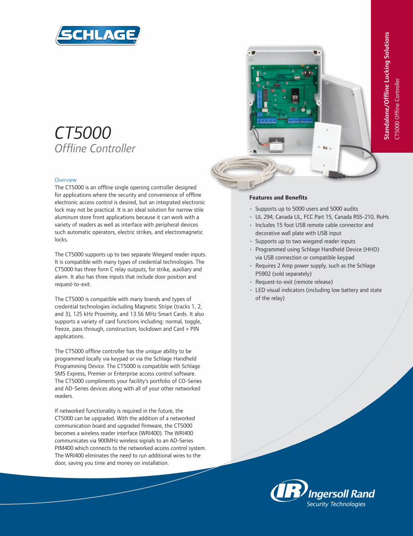
OverviewThe CT5000 is an offline single opening controller designed for applications where the security and convenience of offline electronic access control is desired, but an integrated electronic lock may not be practical. It is an ideal solution for narrow stile aluminum store front applications because it can work with a variety of readers as well as interface with peripheral devices such automatic operators, electric strikes, and electromagnetic locks.
The CT5000 supports up to two separate Wiegand reader inputs. It is compatible with many types of credential technologies. The CT5000 has three form C relay outputs, for strike, auxiliary and alarm. It also has three inputs that include door position and request-to-exit.
The CT5000 is compatible with many brands and types of credential technologies including Magnetic Stripe (tracks 1, 2, and 3), 125 kHz Proximity, and 13.56 MHz Smart Cards. It also supports a variety of card functions including: normal, toggle, freeze, pass through, construction, lockdown and Card + PIN applications.
The CT5000 offline controller has the unique ability to be programmed locally via keypad or via the Schlage Handheld Programming Device. The CT5000 is compatible with Schlage SMS Express, Premier or Enterprise access control software. The CT5000 compliments your facility’s portfolio of CO-Series and AD-Series devices along with all of your other networked readers.
If networked functionality is required in the future, the CT5000 can be upgraded. With the addition of a networked communication board and upgraded firmware, the CT5000 becomes a wireless reader interface (WRI400). The WRI400 communicates via 900MHz wireless signals to an AD-Series PIM400 which connects to the networked access control system. The WRI400 eliminates the need to run additional wires to the door, saving you time and money on installation.
CT5000Offline Controller
Stan
dalo
ne/O
fflin
e Lo
ckin
g So
luti
ons
CT50
00 O
fflin
e Co
ntro
ller
Features and Benefits
• Supports up to 5000 users and 5000 audits• UL 294, Canada UL, FCC Part 15, Canada RSS-210, RoHs• Includes 15 foot USB remote cable connector and
decorative wall plate with USB input• Supports up to two wiegand reader inputs • Programmed using Schlage Handheld Device (HHD)
via USB connection or compatible keypad• Requires 2 Amp power supply, such as the Schlage
PS902 (sold separately)• Request-to-exit (remote release)• LED visual indicators (including low battery and state
of the relay)

877-671-7011 • securitytechnologies.ingersollrand.com
©2012 Ingersoll Rand 004016 11/12
CT5000 Offline Controller Specifications
Users Up to 5000
Audits Up to 5000
Power Supply 12 VDC or 24 VDC (sold separately, must be UL 294 Class 2 listed power supply)
Voltage Range 9.5 VDC to 26 VDC
Connector Cable Specifications
DC Power Input 18AWG, 2 Conductor (Belden 8760 or equivalent) up to 1000 ft (305 m)
Credential Readers (x2)
Data Signals: 22AWG, 6 Conductor (Alpha 1296C or equivalent) up to 500 feet (152 meters) Reader Tamper Signals: 18AWG, Twisted Pair Shielded (Belden 8760 or equivalent) up to 500 feet (152 meters)
Strike/ Aux Relay Outputs
18AWG, 2 Conductor (Belden 8760 or equivalent) up to 2000 feet (610 meters)
Relay Output Tolerances
Strike Output Relay Form C Relay; 6 Amps @ 24VDC or 6 Amps @ 20 VAC or 3 Amps @ 240 VAC
Auxiliary Output Relay
Form C Relay; 6 Amps @ 24VDC or 6 Amps @ 20 VAC or 3 Amps @ 240 VAC
Alarm Output Relay Form C Relay; 6 Amps @ 24VDC or 6 Amps @ 20 VAC or 3 Amps @ 240 VAC
Operating Temperature -31ºF (-35ºC) to 151ºF (66ºC)
Operating Humidity 0 - 100% condensing
Certifications UL 294, Canada UL, FCC Part 15, Canada RSS-210, RoHs
Dimensions 10.43” x 7.28” x 3.79” 26.49 cm x 18.49 cm x 9.63 cm
Programming Method Manually programmed via compatible keypad or computer programmed via SUS Software on the Schlage Handheld Programming Device (HHD)
Optional Accessories 125 foot USB remote cable connector, PS902, PS904, or Von Duprin PS914 (sold separately)
Credential Compatibility (software and reader dependent)
Magnetic Stripe Card Field configurable track 1, 2, or 3
125 kHz Proximity Card Schlage, XceedID® (34X, 35X, 35C, 37X bit formats), HID®, GE/CASI ProxLite™ and AWID® 26 bit format
13.56 MHz Smart Card aptiQ™ smart cards featuring MIFARE DESFire™ EV1 HID iCLASS® CSN only 26 bit format
INGERSOLL RAND, the Ingersoll Rand logo, SCHLAGE, the SCHLAGE logo, XceedID, Von Duprin and aptiQ are trademarks of Ingersoll-Rand plc, its subsidiaries and/or affiliates in the United States and other countries. GE, CASI and ProxLite are trademarks of General Electric Corporation. MIFARE and MIFARE DESFire EV1 are trademarks of NXP B.V. HID and iCLASS are trademarks of HID Corporation. AWID is a trademark of Applied Wireless Identifications Group. Essex Electronics is a registered trademark of Essex Electronics, Inc. Mercury Security is a registered trademark of Mercury Security, Corp. All other trademarks are the property of their respective owners.
Note: PS902 and Von Duprin PS914 are sold separately.
Operator
CT5000 CT5000 CT5000
CardReader
Pushbutton
PS902PowerSupply
ElectricStrike
TPETPE
PS914
CardReader
CardReader
EL Exit Device EL Exit DeviceElectricStrike
Front Door Application
The CT5000 can be used for front door applications
with an automatic operator, electric strike
and card reader
Narrow Stile Application
For narrow stile applications the CT5000
can be used with an electric strike and card
reader
Panic Device Application
The CT5000 and a card reader along with the
Von Duprin 914 Power Supply can control two EL exit devices for
double door applications
PS902PowerSupply
PS902PowerSupply
CT5000Offline Controllers
The following readers are UL 294 listed for use with the CT5000:• Essex Electronics model KTP-162• Mercury Security models MR-5 and MR-20• XceedID model PR10• aptiQ models MT11, MT15, MTK15 and
SM10

OverviewSchlage Utility Software (SUS) is designed specifically for use on the Handheld Device (HHD) as the link between your access control management software and Schlage electronic offline and networked locks and accessories. This solution consolidates and simplifies programming and managing your access control system. The SUS and HHD is used to initialize, configure and test product operation, and also provides an easy way to manage people, audits, locks and other network panel interface devices for simple access control. The intuitive screen layout for the SUS provides easy navigation during use.
For offline products the SUS is utilized to transfer access control data, such as authorized user lists, via the HHD to the locks. The SUS is also utilized to download audit trail information from offline devices to the HHD and then transfer that data to the access control management software.
In addition the SUS can configure other networked electronic devices (including PIM and PIB) and update firmware revision updates to the devices as desired.
The HHD connects with Schlage AD-Series electronic locks and accessories via a USB interface and utilizes Active Synch or Win Mobile Device Manager to communicate with your PC via the USB port. The HHD is also able to connect to the SPED, KC2, CM, CL, CT500, CT1000, CL Controller and WA-Series PIMs via a serial cable connection.
Schlage Utility Software (SUS) on the Handheld Device (HHD)
Features and Benefits
• Handheld Device with Schlage Utility Software installed
• Touch Screen operation• Initialize Lock and Accessories with SUS • Configure and Test Devices• New device template simplifies configuration
Stan
dalo
ne/O
fflin
e Lo
ckin
g So
luti
ons
SUS
on t
he H
andh
eld
Dev
ice
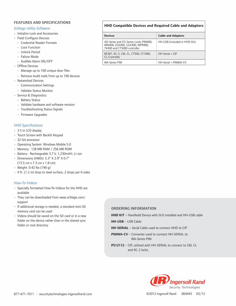
877-671-7011 • securitytechnologies.ingersollrand.com ©2012 Ingersoll Rand 004443 03/12
FEATURES AND SPECIFICATIONS
Schlage Utility Software• Initialize Lock and Accessories• Field Configure Devices
- Credential Reader Formats - Lock Function - Unlock Period - Failure Mode - Audible Alarm ON/OFF
• Offline Devices - Manage up to 100 unique door files
- Retrieve Audit trails from up to 100 devices• Networked Devices
- Communication Settings
- Validate Status Monitor• Service & Diagnostics
- Battery Status - Validate hardware and software revision - Troubleshooting Status Signals
- Firmware Upgrades
HHD Specifications• 3.5 in LCD display• Touch Screen with Backlit Keypad• 32-bit processor • Operating System: Windows Mobile 5.0• Memory: 128 MB RAM / 256 MB ROM• Battery: Rechargeable 3.7 V, 1,230mAH, Li-ion• Dimensions (HWD): 5.3” X 2.9” X 0.7”
(13.5 cm x 7.3 cm x 1.8 cm)• Weight: 0.42 lbs (190 g)• 4 ft. (1.2 m) drop to steel surface, 2 drops per 6 sides
How-To-Videos• Specially formatted How-To-Videos for the HHD are
available• They can be downloaded from www.schlage.com/
support• If additional storage is needed, a standard mini SD
memory card can be used• Videos should be saved on the SD card or in a new
folder on the device rather than in the shared sync folder or root directory
ORDERING INFORMATION
HHD KIT – Handheld Device with SUS installed and HH-USB cable
HH-USB – USB Cable
HH-SERIAL – Serial Cable used to connect HHD to CIP
PIMWA-CV – Converter used to connect HH-SERIAL to WA-Series PIM
P512112 – CIP, utilized with HH-SERIAL to connect to CM, CL and KC-2 locks
HHD Compatible Devices and Required Cable and Adaptors
Devices Cable and Adaptors
AD-Series and CO-Series Locks PIM400, WRI400, ECK400, GCK400, WPR400, TK400 and CT5000 controller
HH-USB (included in HHD-Kit)
BE367, KC-2, CM, CL, CT500, CT1000, CL-Controller
HH-Serial + CIP
WA-Series PIM HH-Serial + PIMWA-CV
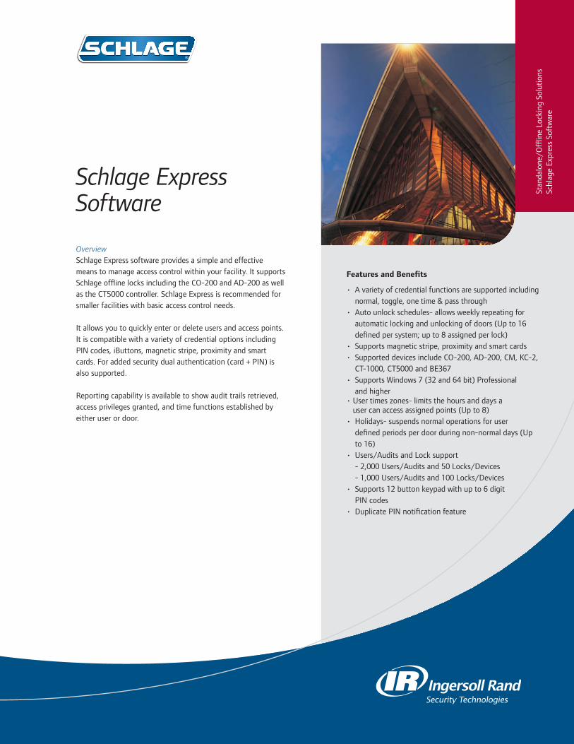
OverviewSchlage Express software provides a simple and effective means to manage access control within your facility. It supports Schlage offline locks including the CO-200 and AD-200 as well as the CT5000 controller. Schlage Express is recommended for smaller facilities with basic access control needs.
It allows you to quickly enter or delete users and access points. It is compatible with a variety of credential options including PIN codes, iButtons, magnetic stripe, proximity and smart cards. For added security dual authentication (card + PIN) is also supported.
Reporting capability is available to show audit trails retrieved, access privileges granted, and time functions established by either user or door.
Schlage Express Software
Features and Benefits
• A variety of credential functions are supported including normal, toggle, one time & pass through
• Auto unlock schedules- allows weekly repeating for automatic locking and unlocking of doors (Up to 16 defined per system; up to 8 assigned per lock)
• Supports magnetic stripe, proximity and smart cards• Supported devices include CO-200, AD-200, CM, KC-2,
CT-1000, CT5000 and BE367 • Supports Windows 7 (32 and 64 bit) Professional
and higher• User times zones- limits the hours and days a
user can access assigned points (Up to 8)• Holidays- suspends normal operations for user
defined periods per door during non-normal days (Up to 16)
• Users/Audits and Lock support - 2,000 Users/Audits and 50 Locks/Devices - 1,000 Users/Audits and 100 Locks/Devices
• Supports 12 button keypad with up to 6 digit PIN codes
• Duplicate PIN notification feature
Stan
dalo
ne/O
fflin
e Lo
ckin
g So
lutio
nsSc
hlag
e Ex
pres
s So
ftw
are

877-671-7011 • securitytechnologies.ingersollrand.com ©2012 Ingersoll Rand 003940 11/12
Specifications
HardwareIntel Pentium II processor (Pentium III or IV recom-mended), CD-Rom, Mouse or compatible pointing device, VGA or Super VGA Monitor, Keyboard
Hard Disk Space 1 GB for software; will require additional space for stored data
Memory 256 MB RAM minimum or the memory required for the operating system, whichever is greater
Operating System Microsoft Windows XP and XP Professional SP1/SP2, Windows Vista 32-bit (except Home or Starter Edition), Windows 7 32-bit & 64-bit Professional and higher
Reports with the built-in viewer Internet Explorer 6 or higher must be installed.
Required for programming
For offline locking system programming using a Schlage approved HHD device the following is required:• Available USB port on the PC• Approved HHD device with installed
communications software and interface cables from Schlage
For offline legacy locking system programming done directly from the PC, the following is required:• Available USB port on the PC• Programming interface cables
ORDERING INFORMATION
SXPR-SFT-1 - Schlage Express software only
Accessories
• HHD KIT - Handheld device to manage Schlage offline locks (USB Cable included for managing AD-Series and CO-Series locks)
• HHD-USB - Additional or replacement cable used to connect HHD to AD-Series and CO-Series products
• HH-Serial - Serial Cable used in conjunction with HHD KIT and CIP for managing legacy Schlage offline locks
• P512112 - Computer interface module used in conjunction with HH-Serial Cable for managing legacy Schlage offline locks
• P101203 - Computer Interface module with ibutton reader used in conjunction with HH-Serial Cable for managing legacy Schlage offline locks
• P394548 - Female/female serial cable. Used to connect computer interface module to laptop/pc
• SDB9USBCBL - six inch cable adapter allows a serial port device to be used with a USB port device (for use with PS12112)
• CRP2 - Proximity Credential Enrollment Reader. Used to read proximity data for enrollment into Schlage Express 4.0 and higher
• CRM2 - Magnetic Stripe Credential Enrollment Reader. Used to read magnetic stripe data for enrollment into Schlage Express 4.0 and higher
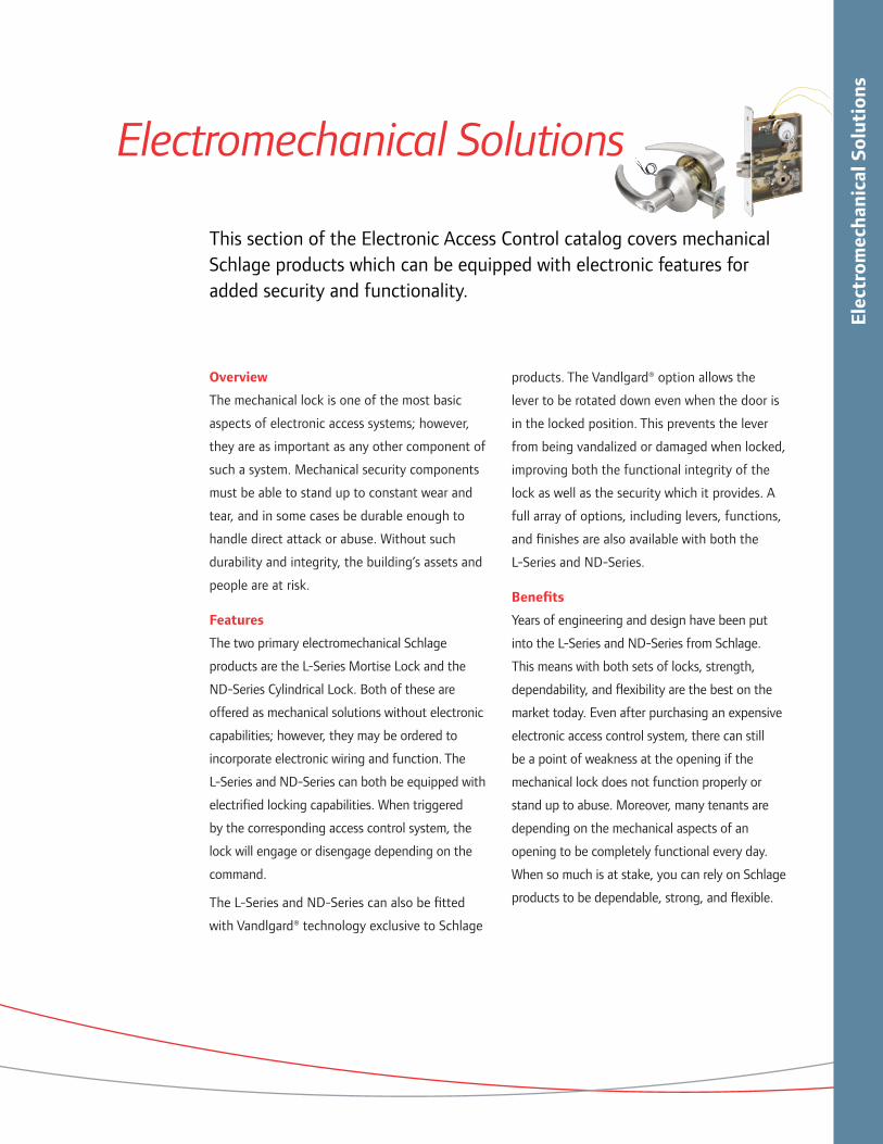
Elec
trom
echa
nica
l Sol
utio
ns
Electromechanical Solutions
This section of the Electronic Access Control catalog covers mechanical Schlage products which can be equipped with electronic features for added security and functionality.
Overview
The mechanical lock is one of the most basic
aspects of electronic access systems; however,
they are as important as any other component of
such a system. Mechanical security components
must be able to stand up to constant wear and
tear, and in some cases be durable enough to
handle direct attack or abuse. Without such
durability and integrity, the building’s assets and
people are at risk.
Features
The two primary electromechanical Schlage
products are the L-Series Mortise Lock and the
ND-Series Cylindrical Lock. Both of these are
offered as mechanical solutions without electronic
capabilities; however, they may be ordered to
incorporate electronic wiring and function. The
L-Series and ND-Series can both be equipped with
electrified locking capabilities. When triggered
by the corresponding access control system, the
lock will engage or disengage depending on the
command.
The L-Series and ND-Series can also be fitted
with Vandlgard® technology exclusive to Schlage
products. The Vandlgard® option allows the
lever to be rotated down even when the door is
in the locked position. This prevents the lever
from being vandalized or damaged when locked,
improving both the functional integrity of the
lock as well as the security which it provides. A
full array of options, including levers, functions,
and finishes are also available with both the
L-Series and ND-Series.
Benefits
Years of engineering and design have been put
into the L-Series and ND-Series from Schlage.
This means with both sets of locks, strength,
dependability, and flexibility are the best on the
market today. Even after purchasing an expensive
electronic access control system, there can still
be a point of weakness at the opening if the
mechanical lock does not function properly or
stand up to abuse. Moreover, many tenants are
depending on the mechanical aspects of an
opening to be completely functional every day.
When so much is at stake, you can rely on Schlage
products to be dependable, strong, and flexible.
Macintosh HD:Users:trighter:Documents:_IngersollRand:EAC_Catalog:005024_EAC_Cat_Electromechanic_Intro:005024_Electromechanical_Intro:005024_Electromechanical_Intro_112012.indd December 7, 2012 1:03 PM Page 87

Elec
trom
echa
nica
l Sol
utio
ns ND-Series Mechanical Specifications
ND-Series Electronic Specifications
ND-Series Electrified Functions
Handing Non-handed
Door Thickness 1-5/8 in. to 2-1/8 in. standard
Backset 2-3/4 in. standard, 3-3/4 in. and 5 in. optional
Faceplate Brass, bronze or stainless steel. 1-1/8 in. x 2-1/4 in. (29mm x 57mm) square corner, beveled.
Lock Chassis Zinc plated for corrosion resistance
Latchbolt Steel, 1/2 in. (12mm) throw, deadlocking on keyed and exterior functions
Exposed Trim Levers: Pressure cast zinc, plated to match finish symbols
Roses Brass, bronze or zinc
Strike ANSI curved lip strike 1-1/4 in. x 4-7/8 in. x 1-3/16 in. lip to center standard
Cylinders and Keys6 pin solid brass cylinder is standard with Everest 29 S123 keyway furnished as default. Furnished with 2 Nickel Silver keys. Additional Schlage keyways available.
Cylinder OptionsAvailable in Full Size Interchangeable Core (FSIC) and Small Format Interchangeable Core (SFIC). Also available less cylinder and less FSIC to allow for Primus XP cylinder usage.
Lever Design Rhodes Lever Handle
Finish Oil Rubbed Bronze 613 & Satin Chromium Plated 626
Function Outside Lever Fail Safe/Secure? Auxillary Latch Inside Lever Vandlgard®
ND12DELContinuously locked
electronicallySafe
Deadlocks latchbolt when door is closed
Always free for immediate exit
No
ND12DEUContinuously locked until unlocked by 24V AC or DC
SecureDeadlocks latchbolt when door is closed
Always free for immediate exit
No
ND80PDELContinuously locked
electronicallySafe
Deadlocks latchbolt when door is closed
Always free for immediate exit
No
ND80PDEUContinuously locked until unlocked by 24V AC or DC
SecureDeadlocks latchbolt when door is closed
Always free for immediate exit
No
ND96PDELContinuously locked
electronicallySafe
Deadlocks latchbolt when door is closed
Always free for immediate exit
Yes
ND96PDEUContinuously locked until unlocked by 24V AC or DC
SecureDeadlocks latchbolt when door is closed
Always free for immediate exit
Yes
Voltage 24V AC or 24V DC
Holding Current .15A or .35A
Operating TemperatureMaximum +151°F (+66°C)Minimum -31°F (-33°C)
Rectifier used on AC operation unit only .35A @ 24V (Current requirements per lock)
Macintosh HD:Users:trighter:Documents:_IngersollRand:EAC_Catalog:005024_EAC_Cat_Electromechanic_Intro:005024_Electromechanical_Intro:005024_Electromechanical_Intro_112012.indd December 7, 2012 1:03 PM Page 88Macintosh HD:Users:trighter:Documents:_IngersollRand:EAC_Catalog:005024_EAC_Cat_Electromechanic_Intro:005024_Electromechanical_Intro:005024_Electromechanical_Intro_112012.indd December 7, 2012 1:03 PM Page 89

Elec
trom
echa
nica
l Sol
utio
nsL-Series Mechanical Specifications
L-Series Electronic Specifications
Handing Non-handed
Door Thickness1-3/4 in. (44mm) standard, 1-3/8 in. (35mm) to 2-1/2 in. (64mm) optional. Over 2-1/2 in. (64mm) door ranges vary by function. Specify door thickness if other than 1-3/4 in.
Backset 2-3/4 in. (70mm) only
Armored Front1-1/4 in. x 8 in. x 7/32 in. (32mm x 203mm x 6mm) standard1-1/16 in. x 8 in. x 7/32 in. (27 mm x 203 mm x 6mm) optional
Case Size 4-7/16 in. x 6-1/16 in. x 1 in. (113mm x 154mm x 25mm)
Spacing Knob or lever to cylinder, 3-7/8 in. (98mm); knob or lever to thumbturn hub, 2-11/16 in. (68mm)
Bolts1 in. (25mm) throw stainless steel deadbolt and 3/4 in. (19mm) throw stainless steel latch with anti-friction tongue
Cylinders and Keys6 pin solid brass cylinder is standard with Everest 29 S123 keyway furnished as default. Furnished with 2 Nickel Silver keys. Additional Schlage keyways available.
Keying OptionsAvailable in Full Size Interchangeable Core (FSIC) and Small Format Interchangeable (SFIC). Also available less cylinder and less FSIC to allow for Primus XP cylinder usage.
StrikeANSI curved lip strike 1-1/4 in. x 4-7/8 in. (32mm x 124mm) x 1-3/16 in. (30mm) lip to center with dust box standard
Trim Combinations Available with knobs both sides, levers both sides, or knob and lever with rose or escutcheon on each side
EscutcheonsL escutcheons are cold forged brass, bronze or stainless steel. N escutcheons are heavy wrought reinforced brass, bronze and stainless steel
Knobs #41 and #42 heavy duty wrought brass, bronze or stainless steel knobs match D-Series knobs
LeversForged brass or bronze and cast stainless steel. Designs available to match ND and S Series levers and also Von Duprin exit devices.
Voltage 24V AC or 24V DC (Max 26V; Min 22V)
Peak Current 1.3 Amps at 5 to 10 second intervals
Holding Current .135 Amps between peak current intervals
Operating TemperatureMaximum +151°F (+66°C)Minimum -31°F (-33°C)
Interfacing devicesHandReaders, wall switches, security consoles, access card readers, thermo-sensitive devices, smoke and fire alarms, telephone access controls, automatic time devices and computerized controls
Micro Switch Electrical Requirements for Request to Exit (RX) Function
Current: 1.0 AmpsVoltage: 24V AC or 24V DCPeak Load: 5 Amps, 250V AC or DC
Macintosh HD:Users:trighter:Documents:_IngersollRand:EAC_Catalog:005024_EAC_Cat_Electromechanic_Intro:005024_Electromechanical_Intro:005024_Electromechanical_Intro_112012.indd December 7, 2012 1:03 PM Page 88Macintosh HD:Users:trighter:Documents:_IngersollRand:EAC_Catalog:005024_EAC_Cat_Electromechanic_Intro:005024_Electromechanical_Intro:005024_Electromechanical_Intro_112012.indd December 7, 2012 1:03 PM Page 89

Elec
trom
echa
nica
l Sol
utio
ns
*Specify L283-263 with L functions, specify L283-239 with LV functions
L-Series Electrified Functions
ND-Series and L-Series Comparison
Function Outside Lever Fail Safe/Secure?
Auxillary Latch Inside Lever Latchbolt
Retract Request to Exit Vandlgard®
L9080ELContinuously
locked electronically
SafeDeadlocks
latchbolt when door is closed
Always free for immediate exit
Latchbolt retracted by key
outside or by lever inside
NoneOptional
(LV9080EL)
L9080EU
Continuously locked until unlocked by
24V AC or DC
SecureDeadlocks
latchbolt when door is closed
Always free for immediate exit
Latchbolt retracted by key
outside or by lever inside
NoneOptional
(LV9080EU)
L9080EL-RX*Continuously
locked electronically
SafeDeadlocks
latchbolt when door is closed
Always free for immediate exit
Latchbolt retracted by key
outside or by lever inside
Allows for non-disruptive means
of immediate egress
Optional (LV9080ELRX)
L9080EU-RX*
Continuously locked until unlocked by
24V AC or DC
SecureDeadlocks
latchbolt when door is closed
Always free for immediate exit
Latchbolt retracted by key
outside or by lever inside
Allows for non-disruptive means
of immediate egress
Optional (LV9080EURX)
L9082ELContinuously
locked electronically
SafeDeadlocks
latchbolt when door is closed
Continuously locked
electronically
Latchbolt is retracted by key on either side
None None
L9082EU
Continuously locked until unlocked by
24V AC or DC
SecureDeadlocks
latchbolt when door is closed
Unlocked by 24V AC or DC
Latchbolt is retracted by key on either side
None None
ND-Series L-Series
Handing Non-handed Field Reversible
Door Thickness 1-5/8 in. to 2-1/8 in. standard1-3/4 in. (44mm) standard, 1-3/8 in. (35mm) to 2-1/2 in. (64mm) optional. Over 2-1/2 in. (64mm) door ranges vary by function. Specify door thickness other than 1-3/4 in.
Backset 2-3/4 in. standard, 3-3/4 in. and 5 in. optional 2-3/4 in. (70mm) only
Levers Pressure cast zinc, plated to match finish symbols
Forged brass, bronze or cast stainless steel. Designs available to match ND and S Series levers and Von Duprin exit devices. 93 lever design: Extruded brass, bronze, or stainless steel
StrikeANSI curved lip strike 1-1/4 in. x 4-7/8 in. x 1-3/16 in. lip to center standard
ANSI curved lip strike 1-1/4 in. x 4-7/8 in. (32mm x 124mm) x 1-3/16 in. (30mm) lip to center with dust box standard
Cylinders and Keys
6 pin solid brass cylinder is standard with Everest 29 S123 keyway furnished as default. Furnished with 2 Nickel Silver keys. Additional Schlage keyways available.
6 pin solid brass cylinder is standard with Everest 29 S123 keyway furnished as default. Furnished with 2 Nickel Silver keys. Additional Schlage keyways available.
877-671-7011 • securitytechnologies.ingersollrand.com ©2012 Ingersoll Rand 005024 11/12
Macintosh HD:Users:trighter:Documents:_IngersollRand:EAC_Catalog:005024_EAC_Cat_Electromechanic_Intro:005024_Electromechanical_Intro:005024_Electromechanical_Intro_112012.indd December 7, 2012 1:03 PM Page 90

OverviewThe most complex electronic access systems still rely on mechanical hardware to operate properly. Advanced electronic technology can go to waste without adequate mechanical locking strength and functionality. The Schlage L-Series is a mortise lock which can be equipped with an electrified locking option. The L-Series Mortise Lock is designed for the highest security applications, featuring a heavy-duty deadbolt and superior strength and durability. The L-Series can serve as the mechanical component to nearly any electronic access system. With the electrified option, the L-Series is wired to two sources; a regulating device and a power source. A regulating device such as a hand or card reader signals the L-Series to lock or unlock, while the power source serves as the energy source to change the status of the lock.
Top of the line security means getting the most of both mechanical and electrical components. The Schlage L-Series has a proven record of performance, strength, and durability from the most trusted name in the industry. Recommended ApplicationsThe L-Series Electrified Mortise Lock is useful for many applications, including but not limited to:• Security control centers• Cashier rooms• Fire safety exits• Equipment rooms• Hazardous material storage
Features & Benefits
• Vandlgard® option prevents damage to internal lock when lever is subjected to force
• Fully wrapped heavy-gauge steel case protects against door edge attacks
• Universal lock case provides up to ten functions in one case
• Features reversible handing without opening the case• Lever rotation up or down for easy use
L-SeriesMortise Electrified Lock
Elec
trom
echa
nica
l Loc
ks
L-Se
ries
Mor
tise
Elec
trifi
ed L
ock

877-671-7011 • securitytechnologies.ingersollrand.com ©2012 Ingersoll Rand 004998 11/12
L-Series Mechanical Specifications
Handing Non-handed
Door Thickness 1 3/4” (44mm) standard, 1 3/8”(35mm) to 2 1/2” (64mm) optional. Over 2 1/2” (64mm) door ranges vary by function. Specify door thickness other than 1 3/4”.
Backset 2 3/4” (70mm) only
Armored Front Standard: 1 1/4” x 8” x 7/32” (32mm x 203mm x 6mm)
Optional: 1 1/16” x 8” x 7/32” (27 mm x 203 mm x 6mm)
Case Size 4 7/16” x 6 1/16” x 1” (113mm x 154mm x 25mm)
Spacing Knob or Lever to cylinder, 3 7/8” (98mm); knob or lever to thumbturn hub, 2 11/16” (68mm)
Bolts 1” (25mm) throw stainless steel deadbolt and 3/4” (19mm) throw stainless steel latch with anti-friction tounge
Cylinders and Keys 6 pin solid brass cylinder is standard with Everest 29 S123 keyway furnished as default. Furnished with 2 Nickel Silver keys. Additional Schlage keyways available.
Keying Options Available in Full Size Interchangable Core (FSIC) and Small Format Interchangable Core (SFIC). Also available less cylinder and less FSIC to allow for Primus XP cylinder usage.
Strike ANSI curved lip strike 1 1/4” x 4 7/8” (32 mm x 124 mm) x 1 3/16” (30mm) lip to center with dust box standard
Trim Combinations Available with knobs both sides, levers both sides, or knob and lever with rose or escutcheon on each side
Escutcheons L escutcheons are cold forged brass or bronze and stainless steel. N escutcheons are heavy wrought reinforced brass, bronze or stainless steel
Knobs #41 and #42 heavy duty wrought brass, bronze or stainless steel knobs match D-Series knobs
Levers See pricebook for details.
L-Series Electronic Specifications
Voltage 24V AC or 24 V DC (Max 26V; Min 22V)
Peak Current 1.3 Amps at 5 to 10 second intervals
Holding Current .135 Amps between peak current intervals
Operating Temperature
Maximum +151°F (+66°C)Minimum -31°F (-33°C)
Interfacing devices HandReaders, wall switches, security consoles, access card readers, thermo-sensitive devices, smoke and ire alarms, telephone access controls, automatic time devices and computerized controls
Micro Switch Electrical Requirements for Request to Exit (RX) Function)
Current: 1.0 AmpsVoltage: 24V AC or 24V DCPeak Load: 5 Amps, 250 V AC or DC
L-Series Electrified Functions
Note: See pricebook for details.

OverviewElectronic access control systems can be installed in a variety of applications, but they always require a mechanical lock to ensure that safety and security needs are met. The Schlage ND-Series is a cylindrical lock which can be equipped with an electrified locking option. It can be quickly and easily installed and integrates with various key systems for field adaptability. The ND-Series serves as the mechanical component to nearly any electronic access system. With the electrified option, the ND-Series is wired to two sources; a regulating device and a power source. A regulating device such as a hand or card reader signals the ND-Series to lock or unlock, while the power source serves as the energy source to change the status of the lock. When it comes to access control, mechanical components can be just as important as their electronic counterparts. The Schlage ND-Series provides versatility and easy installation to complete your access control system.
Features & Benefits
• Vandlgard® option prevents damage to internal lock when lever is subjected to force
• Tested to over four times the ANSI Grade 1 standards• Exceeds ANSI A156.2 series 4000 Grade 1 torque
requirements• Extensive options for lever, finish, handing, and
functions• Can be set to fail safe or fail secure• Is available with request to exit functionality
ND-Series Cylindrical Electrified Lock
Elec
trom
echa
nica
l Loc
ks
ND
-Ser
ies
Cylin
dric
al E
lect
rified
Loc
k

877-671-7011 • securitytechnologies.ingersollrand.com ©2012 Ingersoll Rand 004999 11/12
ND-Series Mechanical Specifications
Handing Non-handed
Door Thickness 1-5/8” to 2-1/8” standard including Vandlgard
Backset 2-3/4” standard, 3-3/4” and 5” optional
Faceplate Brass, bronze or stainless steel. 11/8” x 21/4” (29 mm x 57mm) square corner, beveled.
Lock Chassis Zinc plated for corrosion resistance.
Latchbolt Steel, 1/2” (12mm) throw, deadlocking on keyed and exterior functions. 3/4” (19mm) throw anti-friction latch available for pairs of fire doors.
Exposed Trim Levers
Pressure cast zinc, plated to match finish symbols.
Roses Brass, bronze or zinc.
Strike ANSI curved lip strike 11/4” x 47/8” x 13/16”lip to center standard.
Cylinders and Keys 6 pin solid brass cylinder is standard with Everest 29 S123 keyway furnished as default. Furnished with 2 Nickel Silver keys. Additional Schlage keyways available.
Keying Options Available in Full Size Interchangeable Core (FSIC) and Small Format Interchangeable Core (SFIC). Also available less cylinder and less FSIC to allow for Primus XP cylinder usage.
Lever Design & Finish
All ND levers and all ND finishes available
ND-Series Electronic Specifications
Voltage 24V AC or 24 V DC
Holding Current .35A or .15A
Operating Temperature
Maximum +151°F (+66°C)Minimum -31°F (-33°C)
Rectifier used on AC operation unit only .35A @ 24 (Current requirements per lock)
ND-Series Electrified Functions
Note: See pricebook for details.

Rea
ders
Readers
This section of the Electronic Access Control catalog covers XceedID® Proximity Readers and aptiQ™ Smart and Multi-Technology Readers from Ingersoll Rand Security Technologies.
Overview
Ingersoll Rand offers a comprehensive line of
credential readers with a range of technologies
and form factors to meet a variety of security
needs and budgets. The aptiQ™ line of multi-
technology readers deliver complete flexibility
when transitioning from magnetic stripe or
proximity to smart technology. A variety of reader
designs are available to accommodate a wide
range of mounting applications.
Proximity Readers
• XceedID proximity technology offers your
facility an easy and convenient access control
solution. Proximity technology, which operates
on 125 kHz frequency, is easily integrated into
existing legacy proximity systems or ideal for a
new installation.
• The PR10 proximity mini-mullion reader is
attractive, cost-effective, and well suited for
exterior and interior applications. This reader
also has a sleek and attractive architectural
styling. The PR10 proximity reader by XceedID
offers a visual indicator and audio feedback
representing status and activity information
which make access control simple for users to
understand.
• The proximity reader by XceedID operates on
a Wiegand interface, and is compatible with
industry leading proximity credentials.

Rea
ders
Smart Readers
• The aptiQ™ SM10 mini-mullion smart reader
by Ingersoll Rand Security Technologies is one
of the most secure readers in the industry.
Instead of using open transmission protocols,
the SM10 smart card reader utilizes high
security data. Each message between the card
and the reader is digitally signed using Message
Authentication Coding (MAC) to ensure the
integrity of the data.
• Smart reader technology can be used in
applications such as logical access, cashless
vending, and cafeteria services.
Multi-Technology Readers
• aptiQ™ multi-technology readers are
the most flexible readers in the industry.
Finally, one reader handles all applicable
ISO standards (14443) and can handle
multiple formats simultaneously. aptiQ™
multi-technology readers contain both 125
kHz proximity and 13.56 MHz contactless
smart card capability in one unit, which
allows customers to economically migrate
to the latest in smart card technology at
their own pace.
• aptiQ™ MTMS15 and MTMSK15 multi-
technology magnetic stripe readers
can handle all applicable ISO standards
(14443) and can handle multiple formats
simultaneously. These mult-technology
readers contain the contact technology
of magnetic stripe and both 125 KHz
proximity and 13.56 MHz contactless smart
card capability in one unit.
877-671-7011 • securitytechnologies.ingersollrand.com ©2013 Ingersoll Rand 005025 01/13

OverviewaptiQ™ Multi-Technology Readers by Ingersoll Rand Security Technologies are designed to simplify your access control solutions. Transition your system from proximity to smart card technology at your own pace without having to change out readers as new technologies are available. aptiQ readers handle all applicable ISO standards (14443A, 14443B, 15693), are FIPS 201-1 compliant and are versatile enough to read 125kHz proximity and 13.56MHz contactless smart cards in a single unit. aptiQ multi-technology readers interface with aptiQ smart credentials (MIFARE® classic and MIFARE DESFire™ EV1) and can read the card serial numbers of a variety of smart cards from other manufacturers, making your next upgrade in technology simple and seamless. Additionally, aptiQ readers are already NFC compatible and able to communicate with NFC-enabled phones whenever you’re ready to take that step. aptiQ multi-technology readers use an open architecture platform designed to work with industry standards and common access control system interfaces. Multiple aptiQ reader form factors are designed to fit a variety of placement needs, with an attractive modern design which will complement any facility’s architecture and décor. aptiQ readers are very easy to install with the quick-connect design and a standard wiring color scheme that most technicians are already accustomed to. But if you do have questions, you’ll never worry about lack of service or assistance. As always, our knowledgeable sales & support staff is ready to assist you with any design or technology questions you may have.
Note: Magnetic stripe multi-technology readers also available.
aptiQ™Multi-Technology Readers
Features & Benefits
• Accommodates interior, exterior, metal, and non-metal installation environments
• Recognizes most proximity credentials, and aptiQ smart credentials (MIFARE® classic and MIFARE DESFire™ EV1)
• FIPS 201-1 Compliant • NFC Compatible • Quick-connect design for easy installation • Simple wiring – color scheme is identical to most readers in the market
• Easy-to-install mounting bracket • Tri-state LED (red, green, amber) visual indicator and audio feedback representing status and activity information, easily discernible for the audibly or visually impaired.
• Wiegand output for simple interface with most access control panels
• Multiple reader cover color options • Limited Lifetime Warranty • Multi-technology readers may also be ordered with RS-485 capability
Rea
ders
aptiQ
™ M
ulti-
Tech
nolo
gy R
eade
rs

877-671-7011 • securitytechnologies.ingersollrand.com©
2013 Ingersoll Rand 005354 01/13
aptiQ™
Smart Technology from
Ingersoll Rand enhances the intelligence of products through a secure, open architecture design in readers, credentials, and sm
art phone applications. aptiQ
™ seam
lessly interfaces and comm
unicates with a variety of products, and provides a platform
that easily adapts as new innovations enter the m
arketplace.
ING
ERSO
LL RA
ND
, the Ingersoll Rand logo, Schlage, aptiQ
and XceedID, are tradem
arks of Ingersoll-Rand plc, its subsidiaries and/or affiliates in the U
nited States and other countries. XA
CTT, ISOX Lite are tradem
arks of XceedID Corporation. G
E, CASI and ProxLite are tradem
arks of General Electric Corporation. Inside PicoTag is a tradem
ark of Inside Technologies. M
IFAR
E and MIFA
RE D
ESFire EV1 are tradem
arks of NXP B
.V. HID
and iCLASS are tradem
arks of HID
Corporation. Tag-It is a trademark for Texas Instrum
ents. STMicroelectronics is a
trademark of STM
icroelectronics Inc. AW
ID is a tradem
ark of Applied W
ireless Identifications Group. A
ll other trademarks are the property of their respective ow
ners.
Model*
PR
10SM
10M
T11M
T15M
TK15
Reader Type
Proximity M
ini-Mullion*
Smart M
ini-Mullion*
Multi-Technology M
ullionM
ulti-Technology Single Gang
Multi-Technology Single G
ang Keypad
Frequency125 kH
z13.56 M
Hz
13.56 MH
z and 125 kHz
FIPS 201-1 C
ompliant
No
Yes
Standard Default P
IV O
utputn/a
75 bit PIV**
Standardsn/a
ISO 14443A
, 14443B, 15693
Certifi
cationsFCC Certification IC Certification U
L 294 Listed R&
TTE Directive (15 EU
Countries) CE Mark IP65
Voltage R
ange5-16 V
DC
Pow
er SupplyLinear D
C
Current R
equirement
(at 12 VD
C and 25 C
; mA
mps)
Avg. 65 m
A
Peak 110 mA
Avg. 95 m
A
Peak 195 mA
MT11 A
vg. 100 mA
M
T11 Peak 170 mA
MT11-485 Avg. 115 m
A
MT11-485 Peak 145 m
AM
T15 & M
T15-485 Avg. 120m
A
MT15 &
MT15-485 Peak 200m
AM
TK15 &
MTK
15-485 Avg. 120m
A
MTK
15 & M
TK15-485 Peak 230m
A
Read R
angeProxim
ity: U
p to 3” (7.5 cm)
MIFA
RE: U
p to 3” (7.5 cm)
DESFire EV
1: Up to 2” (5.1 cm
)Proxim
ity: Up to 5” (12.7 cm
) M
IFAR
E: Up to 4” (10 cm
)D
ESFire EV1: U
p to 2” (5.1 cm)
PIV Credential: U
p to 2.5” (6.5 cm)
Cable Specifi
cation18 A
WG
, 5 Conductor Stranded/Shielded
System Interfaces
Wiegand
Wiegand / Clock &
Data
Wiegand / Clock &
Data / R
S-485*** (OSD
P)
Cabling D
istanceW
iegand Output: 500 ft. (152 m
)
Physical D
imensions (H
WD
)4.26” x 1.72” x 0.81”
10.8 cm x 4.4 cm
x 2.1 cm5.91” x 1.72” x 0.81”
15 cm x 4.4 cm
x 2.1 cm5.1” x 3.25” x 0.76”
12.9 cm x 8.3 cm
x 1.9 cm
Operating Tem
peratures-40 to 158F (-40 to 70C)
Weight
4.1 oz3.9 oz
5.7 oz9.1 oz
9.3 oz
Material
PBT Polymer
Technologies Supported in D
efault Mode
Schlage Proximity
XceedID™
Proximity
HID
® Proximity
GE/CA
SI ProxLite® A
WID
® Proximity
LenelProx®
Schlage MIFA
RE® Secure Sector
XceedID™
MIFA
RE® Secure Sector
aptiQ™
MIFA
RE® Secure Sector
aptiQ™
Smart Cards using M
IFAR
E D
ESFire™ EV
1 with PA
CSA
DESFire® CSN
HID
iCLASS® CSN
Inside Contactless PicoTag® CSN
ST M
icroelectronics® CSN
Texas Instruments Tag-It® Serial N
umber
Phillips I-Code® CSN
Schlage Proximity XceedID
™ Proxim
ity HID
® Proximity
GE/CA
SI ProxLite® AW
ID® Proxim
ity LenelProx®
Schlage MIFA
RE® Secure Sector XceedID
™ M
IFAR
E® Secure Sector aptiQ
™ sm
art cards using MIFA
RE® aptiQ
™ Sm
art Cards using MIFA
RE D
ESFire™ EV
1 with PA
CSA
DESFire® CSN
HID
iCLASS® CSN
Inside Contactless PicoTag® CSN ST M
icroelectronics® CSN
Texas Instruments Tag-It® Serial N
umber Phillips I-Code® CSN
Color O
ptionsB
lack (Standard)
CreamCool Tone G
rayW
arm Tone
Brow
n
* Som
e features and benefits listed on the front may not be applicable to the sm
art-only and proximity-only readers.
** O
ther output options available through configuration.
*** RS-485 m
odel numbers include “-485” after the original m
odel number. For exam
ple, MT11-485 is the R
S-485 version of the m
ulti-technology mini-m
ullion reader. Multi-drop, O
pen Standard Device Protocol (O
SDP).

OverviewaptiQ™ Multi-Technology Magnetic Stripe Readers by Ingersoll Rand Security Technologies are designed to simplify your access control solutions. Transition your system from an existing population of magnetic stripe cards to more secure smart card technology at your own pace. aptiQ multi-technology readers are versatile enough to read magnetic stripe, 125 kHz proximity, and 13.56MHz contactless smart cards in a single unit, handle all applicable ISO standards (14443A, 14443B, 15693), and are FIPS 201-1 compliant. aptiQ multi-technology magnetic stripe readers interface with aptiQ™ smart credentials (MIFARE® classic and MIFARE® DESFire™ EV1), and can read the card serial numbers of a variety of smart cards from other manufacturers, making your next upgrade in technology simple and seamless. Additionally, aptiQ readers are already NFC compatible and able to commu nicate with NFC-enabled phones whenever you’re ready to take that step. aptiQ multi-technology magnetic stripe readers use an open architecture platform designed to work with industry standards and common access control system interfaces. And with an attractive modern design they’ll complement any facility’s architecture and décor. aptiQ readers are very easy to install with the quick-connect design and a standard wiring color scheme that most technicians are already accustomed to. But if you do have questions, you’ll never worry about lack of service or assistance. As always, our knowledgeable sales & support staff is ready to assist you with any design or technology questions you may have.
aptiQ™Multi-Technology Magnetic Stripe Readers
Features & Benefits
• Accommodates interior, exterior, metal, and non-metal environments
• Recognizes magnetic stripe credentials, most proximity credentials, and aptiQ™ smart credentials (MIFARE® classic and MIFARE DESFire™ EV1)
• FIPS 201-1 Compliant • NFC Compatible • Quick-connect cable for easy installation • Simple wiring – color scheme is identical to most readers in the market
• Easy-to-install mounting bracket • Tri-state LED (red, green, amber) visual indicator and audio feedback representing status and activity information, easily discernible for the audibly or visually impaired
• Wiegand or RS-485 output for simple interface with most access control panels
• Multiple reader cover color options • Limited Lifetime Warranty • Magnetic stripe track 2 default, tracks 1 and 3 configurable
Rea
ders
aptiQ
™ M
agne
tic S
trip
e R
eade
rs

877-671-7011 • securitytechnologies.ingersollrand.com ©2013 Ingersoll Rand
aptiQ™ Smart Technology from Ingersoll Rand enhances the intelligence of products through a secure, open architecture design in readers, credentials, and smart phone applications. aptiQ™ seamlessly interfaces and communicates with a variety of products, and provides a platform that easily adapts as new innovations enter the marketplace.
INGERSOLL RAND, the Ingersoll Rand logo, Schlage, aptiQ and XceedID, are trademarks of Ingersoll-Rand plc, its subsidiaries and/or affiliates in the United States and other countries. XACTT, ISOX Lite are trademarks of XceedID Corporation. GE, CASI and ProxLite are trademarks of General Electric Corporation. Inside PicoTag is a trademark of Inside Technologies. MIFARE and MIFARE DESFire EV1 are trademarks of NXP B.V. HID and iCLASS are trademarks of HID Corporation. Tag-It is a trademark for Texas Instruments. STMicroelectronics is a trademark of STMicroelectronics Inc. AWID is a trademark of Applied Wireless Identifications Group. All other trademarks are the property of their respective owners.
Model MTMS15 MTMSK15
Reader Type Multi-Technology Magnetic Stripe Multi-Technology Magnetic Stripe with Keypad
Frequency 13.56MHz, 125 kHz, and magnetic stripe
FIPS 201-1 Compliant Yes
Standard Default PIV Output 75 bit PIV*
Standards ISO 14443A, 14443B, 15693
Certifications FCC Certification · IC Certification · UL 294 Listed · R&TTE Directive (15 EU Countries) · CE Mark · IP65
Voltage Range 5-16 VDC
Power Supply Linear DC
Current Requirement(at 12 VDC and 25 C; mAmps)
MTMS15 & MTMS15-485 Avg. 120mAMTMS15 & MTMS15-485 Peak 200mA
MTMSK15 & MTMSK15-485 Avg. 120mAMTKMS15 & MTMSK15-485 Peak 230mA
Read Range
Proximity: Up to 5” (12.7 cm)MIFARE: Up to 4” (10 cm)
DESFire EV1: Up to 2” (5.1 cm)PIV Credential: Up to 2.5” (6.5 cm)
Cable Specification 18 AWG, 5 Conductor Stranded/Shielded
System Interfaces Wiegand / Clock & Data / RS-485** (OSDP)
Cabling Distance Wiegand Output: 500 ft. (152 m)
Physical Dimensions (HWD)4.43” x 5.17” x 1.15”
11.25 cm x 13.13 cm x 2.92 cm
Operating Temperatures -31 to 151F (-35 to 67C)
Weight 8.9 oz 9.5 oz
Material PBT Polymer
Technologies Supported in Default Mode
Magnetic Stripe (tracks 1, 2, or 3)***
Schlage Proximity XceedID™ Proximity HID® Proximity GE/CASI ProxLite® AWID® Proximity
LenelProx® Schlage MIFARE® Secure Sector XceedID™ MIFARE® Secure Sector
aptiQ™ smart cards using MIFARE® aptiQ™ Smart Cards using MIFARE DESFire™ EV1 with PACSA
DESFire® CSN HID iClass® CSN Inside Contactless PicoTag® CSN ST Microelectronics® CSN
Texas Instruments Tag-It® Serial Number Phillips I-Code® CSN
Color Options Black (Standard) Cream†
Cool Tone Gray†
Warm Tone Brown†
* Other output options available through configuration.
** RS-485 model numbers include “-485” after the original model number. For example, MTMS15-485 is the RS-485 version of the multi-technology mini-mullion reader. Multi-drop, Open Standard Device Protocol (OSDP).
*** By default, the MTMS15 and MTMSK15 readers will read track 2 of the magnetic strip. If you require the ability to read track 1 or track 3, please contact Technical Support at 1-877-671-7011 for configuration options.
† Lead Time may apply for non-standard colors
009209 01/13

OverviewaptiQ™ Smart and Multi-Technology Readers by Ingersoll Rand have been approved by the U.S. Government under HSPD-12 for FIPS 201-1 compliance as PIV Transparent Readers. PIV compliance is available on six reader models, including the SM10 Smart Mini-Mullion, MT11 Multi-technology Mullion, MT15 Multi-technology Single Gang, MTK15 Multi-technology Single Gang with Keypad, MTMS15 Multi-technology Magnetic Stripe and MTMSK Multi-technology Magnetic Stripe with Keypad.
aptiQ™ Multi-Technology readers are a unique and critical component of successful security upgrades in all sectors of the government. FIPS 201-1 is a Federal Information Processing Standard (“FIPS”) developed by the National Institute of Standards and Technology (“NIST”) to satisfy the requirements of HSPD-12, a Homeland Security Presidential Directive. One of the main objectives of HSPD-12 is to ensure government-wide interoperability for information technology and security through the implementation of a range of federal standards and product requirements. FIPS 201-1 seeks to improve identifica-tion and authentication of Federal employees and contractors for access to the Federal factilities and information systems.
aptiQ™ FIPS 201-1 PIV compliant readers are available with multiple data output formats, which provide unprecedented versatility within the PIV & PIV-I specification.
In addition to reading approved FIPS 201-1 PIV & PIV-I credentials, aptiQ™ Smart and Multi-technology readers are also compatible with many standard proximity and leading smart card technologies (see specifications). The ability to read multiple existing card types and PIV & PIV-I cards simultane-ously is a tremendous benefit to those agencies looking to transition seamlessly from older proximity technologies to new, mandated PIV & PIV-I credentials. A mixed population of old prox credentials and new PIV & PIV-I credentials is unavoidable during the government’s multi-year upgrade path to FIPS 201-1 compliance.
FIPS 201-1 Compliant Readers
Features & Benefits
• Compatibility: compatible with industry standard magnetic stripe technology (tracks 1,2, or 3) and 125 kHz and 13.56 MHz contactless technologies
• Read Range: up to 6 inches (proximity), up to 2 inches for PIV & PIV-I credentials
• Tri-state LED (red, green, amber): Visual indicator and audio feedback representing status and activity information
• Tamper Detection• Environment: accommodates interior, exterior, metal
and non-metal installation environments
Rea
ders
FIPS
201
-1 C
ompl
iant
Rea
ders

877-671-7011 • securitytechnologies.ingersollrand.com ©2013 Ingersoll Rand 004256 01/13
Please see individual data sheets for each reader for more specific technical information.
ADDITIONAL FEATURES
• Compliance: compatible with applicable ISO standards• Compatible with all access control systems that
support Wiegand format • Warranty: limited lifetime against defective
workmanship and materials• Additional Technologies Supported
- Magnetic Stripe • Track 1, 2, or 3
- Proximity • Schlage • XceedID® • HID® Proximity (certain formats) • GE/CASI ProxLite™ • AWID® Proximity
- Smart Card (secure sector only) • Schlage • aptiQ™ using MIFARE® • aptiQ™ using MIFARE DESFire™ EV1 • FIPS 201-1/PIV & PIV-I
- Smart Card (card serial number only) • DESFire® Application HID iClass® • Inside Contactless PicoTag™
ORDERING INFORMATION
SM10 - Smart Mini-Mullion Reader
MT11 - Multi-Technology Mullion Reader
MT15 - Multi-Technology Single Gang Reader
MTK15 - Multi-Technology Single Gang Reader with Keypad
MTMS15 - Multi-Technology Magnetic Stripe Reader
MTMSK15 - Multi-Technology Magnetic Stripe Reader with Keypad
aptiQ™ PIV readers have been approved by the GSA lab as compliant with FIPS 201-1 and the appropriate PIV credentials.
INGERSOLL RAND, the Ingersoll Rand logo and XceedID, are trademarks of Ingersoll-Rand plc, its subsidiaries and/or affiliates in the United States and other countries. XACTT, ISOX Lite are trademarks of XceedID Corporation. Inside PicoTag is a trademark of Inside Technologies. GE, CASI and ProxLite are trademarks of General Electric Corporation. MIFARE and MIFARE DESFire EV1 are trademarks of NXP B.V. HID and iCLASS are trademarks of HID Corporation. AWID is a trademark of Applied Wireless Identifications Group. All other trademarks are the property of their respective owners.

OverviewThe SERlll Scramble Keypad is a keypad reader designed to prevent onlookers from detecting the PIN code being entered. The LED’s display a randomly allocated set of numbers from 0 to 9. The position of the numbers change every time the keypad is activated. Only the user standing directly in front of the keypad can see the scrambled digits.
Features and Benefits
• Very narrow viewing angle of the lighted, scrambled digits
• The membrane keypad is extremely durable• Random allocation of digits ensures even wear to the
keys• Individual PIN codes can be up to 9 digits in length• The SERlll has a weatherproof rating of IP65• An audible alarm signals when a button is depressed• Robust polycarbonate enclosure• The unit is equipped with power-up diagnostics and
self-test routine• The SERlll is provided with Wiegand communication
protocol• Over 3.6 million unique permutations are available• Terminal connection on the rear of the unit
SERIII-W Scramble Keypad
Rea
ders
SER
III-W
Scr
ambl
e Ke
ypad
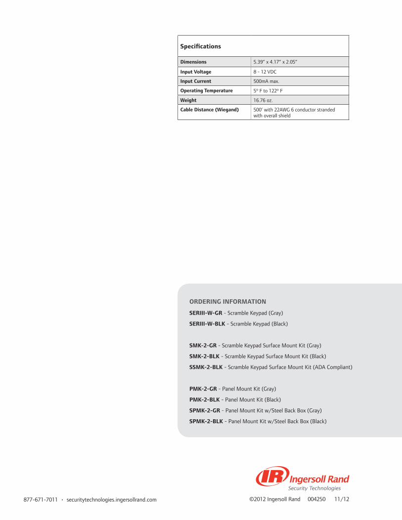
877-671-7011 • securitytechnologies.ingersollrand.com ©2012 Ingersoll Rand 004250 11/12
ORDERING INFORMATION
SERIII-W-GR - Scramble Keypad (Gray)
SERIII-W-BLK - Scramble Keypad (Black)
SMK-2-GR - Scramble Keypad Surface Mount Kit (Gray)
SMK-2-BLK - Scramble Keypad Surface Mount Kit (Black)
SSMK-2-BLK - Scramble Keypad Surface Mount Kit (ADA Compliant)
PMK-2-GR - Panel Mount Kit (Gray)
PMK-2-BLK - Panel Mount Kit (Black)
SPMK-2-GR - Panel Mount Kit w/Steel Back Box (Gray)
SPMK-2-BLK - Panel Mount Kit w/Steel Back Box (Black)
Specifications
Dimensions 5.39” x 4.17” x 2.05”
Input Voltage 8 - 12 VDC
Input Current 500mA max.
Operating Temperature 5º F to 122º F
Weight 16.76 oz.
Cable Distance (Wiegand) 500’ with 22AWG 6 conductor stranded with overall shield

OverviewThe SMR10 and SMR20 Stripe Readers have a slim, mullion style design. The die cast metal housing makes it ideal for indoor or outdoor applications. The SMR20 has a 12 position membrane style keypad.
Features and Benefits
• Rugged Metal Housing• All stainless steel hardware is standard• Audiovisual indication provides Two LED’s (red/green)
and beeper sounds• Static Discharge Protection• Accepts low or high coercivity-magnetic cards• Standard Track 2 encoding (Track 1 & 3 are available)• One security screw mounting• Supports Wiegand or Clock & Data interface formats via
Dip Switches
SMR10 and SMR20 Magnetic Stripe Readers
Rea
ders
SMR
10 &
SM
R20
Mag
Str
ipe
Rea
ders

877-671-7011 • securitytechnologies.ingersollrand.com ©2012 Ingersoll Rand 004246 11/12
ORDERING INFORMATION
SMR10-5V-BLK - 5 VDC standard, Magnetic Stripe Card Reader (black)
SMR10-5V-BG - 5 VDC standard, Magnetic Stripe Card Reader (beige)
SMR10-12V-BLK - 12 VDC Magnetic Stripe Card Reader (black)
SMR10-12V-BG - 12 VDC Magnetic Stripe Card Reader (beige)
SMR20-5V-BLK - 5 VDC standard, Magnetic Stripe Card Reader w/keypad (black)
SMR20-5V-BG - 5 VDC standard, Magnetic Stripe Card Reader w/keypad (beige)
SMR20-12V-BLK - 12 VDC Magnetic Stripe Card Reader w/keypad (black)
SMR20-12V-BG - 12 VDC Magnetic Stripe Card Reader w/keypad (beige)
Specifications
Dimensions 1.95”W x 1.3”H x 5.5’L
Power requirements 5 or 12 VDC
Power consumption 20 mA at 12 VDC
Operating Temperature -40º F to 170º F
Weight 10 oz.
Cable Distance 500’ with 18AWG 6 conductor stranded with overall shield
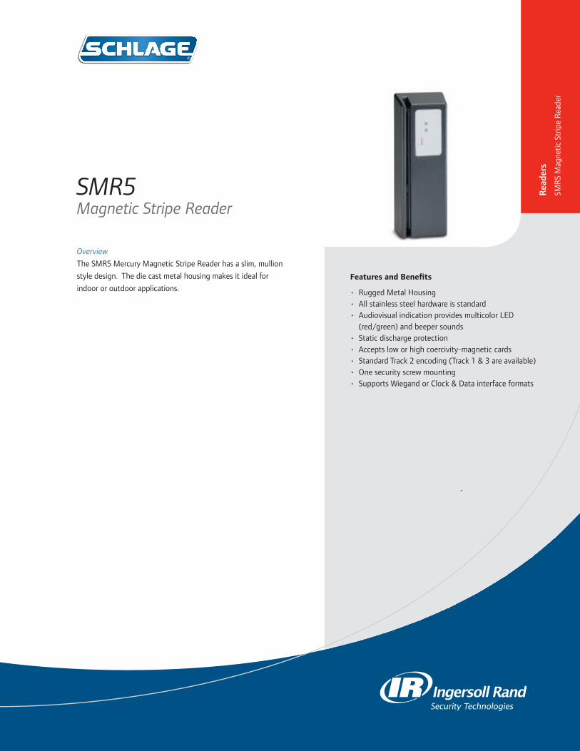
Overview
The SMR5 Mercury Magnetic Stripe Reader has a slim, mullion
style design. The die cast metal housing makes it ideal for
indoor or outdoor applications. Features and Benefits
• Rugged Metal Housing• All stainless steel hardware is standard• Audiovisual indication provides multicolor LED
(red/green) and beeper sounds• Static discharge protection• Accepts low or high coercivity-magnetic cards• Standard Track 2 encoding (Track 1 & 3 are available)• One security screw mounting• Supports Wiegand or Clock & Data interface formats
SMR5 Magnetic Stripe Reader
Rea
ders
SMR
5 M
agne
tic S
trip
e R
eade
r

877-671-7011 • schlage.com ©2012 Ingersoll Rand 004253 11/12
ORDERING INFORMATION
SMR5-5V-BLK - 5 VDC Magnetic Stripe Card Reader (black)
SMR5-5V-BG - 5 VDC Magnetic Stripe Card Reader (beige)
SMR5-12V-BLK - 12 VDC Magnetic Stripe Card Reader (black)
SMR5-12V-BG - 12 VDC Magnetic Stripe Card Reader (beige)
Specifications
Dimensions 1.95”W x 1.3”H x 5.5’L
Power requirements 5 or 12 VDC
Power consumption 20 mA at 12 VDC
Operating Temperature -40º F to 170º F
Weight 10 oz.
Cable Distance 500’ with 18AWG 6 conductor stranded with overall shield

OverviewThe fully encapsulated Electronic Keypad can be used byitself or next to another reader device for additional security. Itsstainless steel construction is ideal for indoor or outdoorapplications. The two designs, single gang box or the mullion mount style, give it the diversity needed for any application.
Features and Benefits
• Field selectable keypad configurations• SEKPDWG mounts directly to a single gang
electrical box• SEKPDMGW mounts to any mullion style frame• No moving parts to replace
SEKPDWG and SEKPDMGW Electronic Keypads
Rea
ders
SEK
PDW
G &
SEK
PDM
GW
Key
pads

877-671-7011 • securitytechnologies.ingersollrand.com ©2011 Ingersoll Rand 004252 11/11
ORDERING INFORMATION
SEKPDWG - Single Gang Style Keypad
SEKPDMGW - Mullion Style Keypad
SEKPD8B - Mullion Style Keypad (8 Bit)
Note: Specify 5V or 12V
Specifications
Dimensions SEKPDWG: 5.125” x 3.375” x .437”SEKPDMGW: 7.125” x 1.75” x .75”
Power supply 5-12 VDC (field selectable)
Operating temperature -40º F to 160º F
Weight SEKPDWG: 16 oz.SEKPDMGW: 4.4 oz
Material 316L Stainless Steel
Standby current draw SEKPDWG: 5V-20mA,SEKPDMGW: 5V-20mA
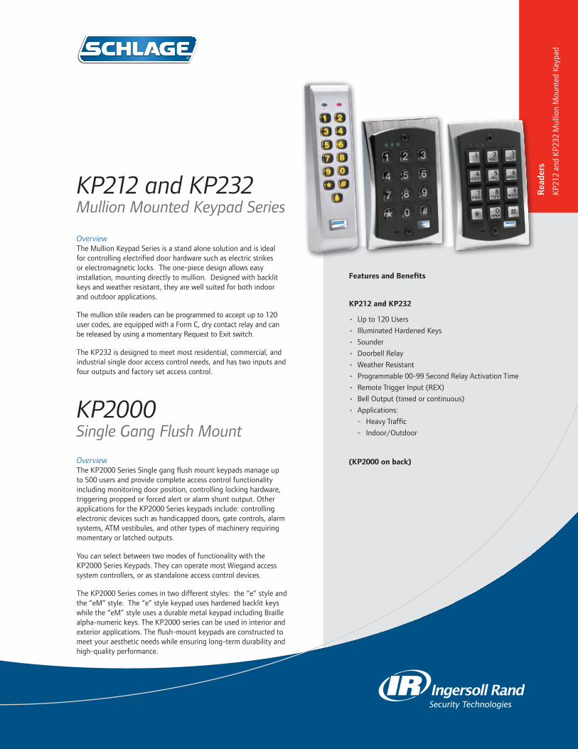
OverviewThe Mullion Keypad Series is a stand alone solution and is ideal for controlling electrified door hardware such as electric strikes or electromagnetic locks. The one-piece design allows easy installation, mounting directly to mullion. Designed with backlit keys and weather resistant, they are well suited for both indoor and outdoor applications.
The mullion stile readers can be programmed to accept up to 120 user codes, are equipped with a Form C, dry contact relay and can be released by using a momentary Request to Exit switch.
The KP232 is designed to meet most residential, commercial, and industrial single door access control needs, and has two inputs and four outputs and factory set access control.
KP2000Single Gang Flush Mount
OverviewThe KP2000 Series Single gang flush mount keypads manage up to 500 users and provide complete access control functionality including monitoring door position, controlling locking hardware, triggering propped or forced alert or alarm shunt output. Other applications for the KP2000 Series keypads include: controlling electronic devices such as handicapped doors, gate controls, alarm systems, ATM vestibules, and other types of machinery requiring momentary or latched outputs.
You can select between two modes of functionality with the KP2000 Series Keypads. They can operate most Wiegand access system controllers, or as standalone access control devices.
The KP2000 Series comes in two different styles: the “e” style and the “eM” style. The “e” style keypad uses hardened backlit keys while the “eM” style uses a durable metal keypad including Braille alpha-numeric keys. The KP2000 series can be used in interior and exterior applications. The flush-mount keypads are constructed to meet your aesthetic needs while ensuring long-term durability and high-quality performance.
KP212 and KP232Mullion Mounted Keypad Series
Features and Benefits
KP212 and KP232
• Up to 120 Users
• Illuminated Hardened Keys
• Sounder
• Doorbell Relay
• Weather Resistant
• Programmable 00-99 Second Relay Activation Time
• Remote Trigger Input (REX)
• Bell Output (timed or continuous)
• Applications:
- Heavy Traffic
- Indoor/Outdoor
(KP2000 on back)
Rea
ders
KP2
12 a
nd K
P232
Mul
lion
Mou
nted
Key
pad

877-671-7011 • securitytechnologies.ingersollrand.com ©2011 Ingersoll Rand 005000 12/11
• Widest array of user type options including single use
and two man rule
• 10-30 VDC and 12-24 VAC operation
• Over-voltage protection for reliable operation
• Single-gang flush mount design
• Indoor/outdoor use
• Keypad programmable
• Key press feedback via sounder and yellow LED
• Built-in assignable sounder
• Bi-color Red/Green LED indicates relay status
Reader Specifications
Feature Set KP212 KP232 KP2000E KP2000EM
Mounting Mullion Mullion Single Gang/Flush Single Gang/Flush
Users 120 120 500 500
PIN Length 1-6 digits 1-6 digits 1-10 digits 1-10 digits
Duty Cycles Medium Medium Medium Heavy Duty
Back Light Yes Yes Yes No
Keys Hard Plastic Hard Plastic Heavy Duty Plastic Heavy Duty Metal w Braille
Weather Resistant Indoor/Outdoor Indoor/Outdoor Indoor/Outdoor Indoor/Outdoor
Doorbell Key Yes Yes No No
Wiegand Output No No No No
Remote Trigger (REX) Yes Yes Yes Yes
Access Control Functionality
Programmable relay activation time (0-99 seconds). Perfect for electric or magnetic locks requiring momentary control.
4 dedicated relay outputs (Lock release, door forced, door propped and alarm shunt)
Monitors DPS, controls various electronic hardware, triggers door propped, forced door alert or alarm shunt
Monitors DPS, controls various electronic hardware, triggers door propped, forced door alert or alarm shunt
Relays 2 Relays (Main and Aux)Main, Prop Door, Forced Door and Alarm Shunt Relay
2 Form C, expandable to 10 programmable outputs
2 Form C, expandable to 10 programmable outputs
Outputs 2 Independent (configurable) 4 Independent (dedicated)2 Independent (Programmable with the option to add 8 more)
Programmable
Finish Aluminum Aluminum Aluminum Aluminum
UL 294 No No Yes Yes
KP2000 Features
• 500 users
• Door position input
• Request to Exit input
• 2 Form C SPDT relay outputs – default for access control
function
• Sounder for key press and alert conditions
• All outputs can be programmed independently if required
• Option for secure installation with control electronics in
protected area

OverviewThe CRM2 Magnetic Stripe Credential Enrollment Reader and the CRP2 Proximity Credential Enrollment Reader are designed to allow easy enrollment of credentials into the Schlage Express access control system. These compact readers eliminate the need for manual data entry, and provide error-free identifica-tion and security throughout the workplace. The plug and play functionality provided via a convenient USB connection allows either of these readers to seamlessly integrate with the Schlage Express software. Additionally, the reader allows for keystrokes to be added before and after the card’s data, providing flex-ibility and data customization.
Note: Compatible with Schlage Express version 4.0 and higher
Features and Benefits
CRM2• Magnetic stripe reader• Reads data from any data track location on the card• USB connectivity• Plug-and-play functionality CRP2• Proximity reader• USB connectivity• Plug-and-play functionality
CRM2 and CRP2Enrollment Readers
Rea
ders
CRM
2 an
d CR
P2 E
nrol
lmen
t R
eade
rs

877-671-7011 • securitytechnologies.ingersollrand.com ©2012 Ingersoll Rand 005132 11/12
CRP2 Specifications
Typical Maximum read range: 1.0” – 3.0” (2.5 – 7.6cm) dependent upon proximity card type and environmental conditions
Dimensions: 3 3/8” x 2” x 0.6”
Weight: 0.45 lbs (12.7g)
Power supply and interface: USB self-powered
Indicators: Tri-state LED, beeper
Transmit frequency: 125 kHz
Operating temperature range: -22° to 150°F (-30° to 65°C)
Operating humidity range: 5% to 95% relative humidity, non-condensing
Storage temperature range: -40° to 185°F (-40° to 85°C)
Certifications: FCC, United States; CE Mark Europe, C-tic Australia, RoHS
Warranty: One year for material/workmanship and defects
CRM2 Specifications
Desktop Dimensions: 3.674” x 1.325” x 1.193” (93.32 x 33.65 x 30.3 mm); Optional base: 3.375” x 3.5” x 0.5” (86 x 89 x 13 mm)
Desktop Weight: 4.6 oz. (136g); Base: 13 oz. (369g)
Media Thickness: 0.015” (0.127 mm) to 0.038” (1.14 mm)
Slot Width: 0.040” (1.0 mm)
Swipe Speed: 3 to 60 inches per second, bi-directional
Power Supply and Interface: USB: self-powered; RS-232 [DB9F] model: 5V supplied by either PS/2 keyboard pass-through or USB power tap
Indicators: Tri-state LED, beeper
Operating Temperature Range: 32° to 131°F (0° to 55°C)
Operating Humidity Range: 5% to 95% relative humidity, non-condensing
Storage Temperature Range: -22° to 158°F (-30° to 70°C)
Cable Length: 6-foot articulated cable
Operating Life: 1,000,000 cycles minimum
Warranty: One year for material/workmanship and defects

Cre
dent
ials
Credentials
This section of the Electronic Access Control catalog covers proximity, smart, and multi-technology credentials from Ingersoll Rand Security Technologies.
Overview
XceedID® and aptiQ™ by Ingersoll Rand Security
Technologies offers a comprehensive line of smart,
multi-technology and proximity credentials with an
array of technological capabilities and form factors
to meet the security needs and budget of virtually
any customer. Ingersoll Rand has a full offering of
credentials to provide complete flexibility when
transitioning from proximity to smart technology.
Additionally, a variety of designs are available to
accommodate a wide range of needs, from ISO
card styles for name badges to keyfobs.
Proximity Credentials
• XceedID proximity technology offers your facility
an easy and convenient access control solution.
Proximity technology, which operates on 125
kHz frequency, is easily integrated into existing
legacy proximity systems and new installations.
• Offered in several different form factors, XceedID
has the proximity credentials to meet your needs.
- The clamshell style is highly durable and
more ridged than the typical credit card,
making this card ideal for harsh environments.
- The ISO style card is similar in size and
thickness to a credit card and has the ideal
surface to print custom artwork, images, and
photographs for identification. This card can
also include a magnetic stripe.
- The keyfob can be easily attached to any key
ring for convenience.
- The PVC patch credential can be adhered to
any frequently used surface.
• Proximity credentials by XceedID are compatible
with most industry leading proximity readers and
are completely ISO compliant. These credentials
also have a passive design, requiring no batteries
or maintenance for the life of the card.

Cre
dent
ials
Smart Credentials
• aptiQ™ contactless smart credentials (MIFARE®
and MIFARE DESFire™ EV1) put you in control
by delivering smarter solutions. Storage options
of 2.5k, 8k, 16k, 32k, or 64k bits will meet the
most demanding storage requirements, and
allow for a wide range of card applications to
be utilized.
• Aside from physical access, smart credential
uses could include transit and point of sale
applications, such as cashless vending and
cafeteria services.
• aptiQ smart credentials operate on 13.56 MHz
frequency, and utilize high security encrypted
data, which is mutually authenticated in
communication between the card and reader,
providing optimum security.
• Smart credentials are also offered in clamshell
style, ISO style cards, keyfobs, and PVC
patches.
Multi-Technology Credentials
• aptiQ multi-technology credentials are
extremely flexible. Particularly useful during
a transition from proximity technology to
smart technology, this card can be read by
both proximity readers and smart readers,
which allows customers to economically
migrate to the latest in smart technology at
their own pace.
• This type of credential is only available in an
ISO style card.

Cre
dent
ials
125 kHz Proximity Credentials125 kHz/13.56 MHz
Multi-Technology Credentials
Model Number 7410 7510 7610 7710 9951 9958 8920/8940/8980
Credential Type Clamshell ISO-Glossy White* Keyfob PVC Disk ISO-Glossy White*
Credential Technology; ISO Standard
125 kHz Prox 125 kHz Prox 125 kHz Prox 125 kHz Prox125 kHz Prox/MIFARE;
ISO 14443
125 kHz Prox/MIFARE DESFire™
EV1; ISO 14443
Dimensions (HWT in inches)
3.37 x2.125 x0.075
3.37 x2.125 x0.033
2 x1.24 x0.38
1.38 in. or 35mm diameter
3.37x2.125 x0.033
Slot Punch (Printed Guide)
Vertical (Punched)
Vertical or Horizontal
Key Ring N/A Vertical
Memory Capacity; Application Sectors
N/A N/A N/A N/A8k bit/
1K byte; 16 sectors
32k bit/ 4K byte;
40 sectors2K/4K/8K byte
*All ISO glossy white cards are printable with a magnetic stripe option. Add M1 to the model number for magnetic stripes when ordering.

Cre
dent
ials
13.56 MHz Smart Credentials
Model Number 9420 9451 9520 9551 9558 9651 9751 97588420/ 8440/ 8480
8520/ 8540/ 8580
8620/ 8640/ 8680
8720/ 8740/ 8780
Credential Type Clamshell ISO-Glossy White* Keyfob PVC Patch ClamshellISO
Glossy White*
Keyfob PVC Disk
Credential Technology; ISO Standard
MIFARE Lite; ISO 14443
MIFARE; ISO
14443MIFARE; ISO 14443
MIFARE; ISO
14443MIFARE; ISO 14443
MIFARE DESFireE
EV1
MIFARE DESFireE
EV1
MIFARE DESFireE
EV1
MIFARE DESFireE
EV1
Dimensions (HWT in inches)
3.37x2.125 x0.075
3.37x2.125x0.0332
x1.24 x0.38
3.32x2.08x0.033.37
x2.125 x0.033
3.37 x2.125 x0.033
2 x1.24 x0.38
1.38 in. or 35mm diameter
Slot Punch (Printed Guide)
Vertical (Punched) Vertical or Horizontal Key Ring VerticalVertical
(Punched)Vertical or Horizontal
Key Ring N/A
Memory Capacity; Application Sectors
2.5k bit; 5 sectors
8k bit/ 1K byte;
16 sectors
2.5k bit; 5 sectors
8k bit/ 1K byte;
16 sectors
32k bit/ 4K byte;
40 sectors
8k bit/ 1K byte;
16 sectors
8k bit/ 1K byte;
16 sectors
32k bit/ 4K byte;
40 sectors
2k/4k/8k bytes
2k/4k/8k bytes
2k/4k/8k bytes
2k/4k/8k bytes
877-671-7011 • securitytechnologies.ingersollrand.com ©2013 Ingersoll Rand 005388 01/13
*All ISO glossy white cards are printable with a magnetic stripe option. Add M1 to the model number for magnetic stripes when ordering.

OverviewaptiQ™ contactless smart credentials put you in control by delivering smarter solutions. These credentials protect your most sensitive data by utilizing extra layers of security protection, and can be used for many other applications including transit, cashless vending, and cafeteria point of sale.
aptiQ™ contactless smart credentials operate on a 13.56 MHz frequency, and utilize high security encrypted data, which is mutually authenticated in communication between the card and reader, providing optimum security. aptiQ™ smart credentials offer the choice of 2.5k, 8k, 16k, 32k, and 64k bits of storage, which will meet the most demanding storage requirements.
Smart Credentials
Features & Benefits
• Open architecture design is built on ISO 14443A standards, providing for a faster data transfer speed
• Offered in clamshell, ISO style cards, key fobs, and adhesive patches
• Utilize MIFARE® or MIFARE DESFire™ EV1 technology
Cre
dent
ials
Smar
t Cr
eden
tials

877-671-7011 • securitytechnologies.ingersollrand.com ©2013 Ingersoll Rand 005424 01/13
13.56 MHz Smart Credentials
Model Number 9420 9451 9520 9551 9558 9651
Credential Type Clamshell ISO-Glossy White1 Keyfob
Credential Technology; ISO Standard
MIFARE; ISO 14443 MIFARE; 14443
Dimensions (HWT in inches)
3.37x2.125x0.075 3.37x2.125x0.033 2x1.24x0.038
Slot Punch (Printed Guide)
Vertical (Punched) Vertical or Horizontal Key Ring
Memory Capacity; Application Sectors
2.5k bit; 5 sectors
8k bit/ 1K byte;
16 sectors
2.5k bit; 5 sectors
8k bit/1K byte; 16 sectors
32k bit/ 4K byte;
40 sectors
8k bit/1K byte; 16 sectors
WarrantyLifetime - Credentials have a lifetime warranty against manufacturers defects.
See sales policy for complete warranty details.
13.56 MHz Smart Credentials
Model Number 9751 9758 8420/8440/8480 8520/8540/8580 8620/8640/8680 8720/8740/8780
Credential Type PVC Patch Clamshell ISO-Glossy White1 Keyfob PVC Disk
Credential Technology; ISO Standard
MIFARE; ISO 14443 MIFARE DESFire EV1
Dimensions (HWT in inches)
3.37x2.125x0.033 3.37x2.125x0.075 3.37x2.125x0.033 2x1.24x0.28 35mm
Slot Punch (Printed Guide)
Vertical Vertical (Punched)Vertical or Horizontal
Keyring N/A
Memory Capacity; Application Sectors
8k bit/1K byte; 16 sectors
32k bit/4K byte; 40 sectors
2K/4K/8K byte
WarrantyLifetime - Credentials have a lifetime warranty against manufacturers defects.
See sales policy for complete warranty details.
1 ISO Glossy White style credentials are made from composite material, are printable, and can include a magnetic stripe as an option. Add M1 to the model number for a magnetic stripe when ordering.
INGERSOLL RAND, the Ingersoll Rand logo, and aptiQ are trademarks of Ingersoll-Rand plc, its subsidiaries and/or affiliates in the United States and other countries.

OverviewaptiQ™ multi-technology credentials are extremely flexible. Particularly useful during a transition from proximity technology to smart technology, this card can be read by both proximity readers and smart readers. This allows customers to economically migrate to the latest smart technology at their own pace.
aptiQ™ multi-technology credentials contain both 125 kHz proximity and 13.56 MHz contactless smart card capability in one unit, and are available in the newest technologies of today, including both MIFARE® and MIFARE DESFire™ EV1 technology.
Multi-Technology Credentials
Features & Benefits
• Open architecture design is built on ISO 14443A standards, providing for a faster data transfer speed
• Only available in ISO style cards• Utilize 125 kHz proximity and 13.56 MHz MIFARE®
technology or 125 kHz proximity and 13.56 MHz MIFARE DESFire™ EV1 technology
Cre
dent
ials
Mul
ti-Te
chno
logy
Cre
dent
ials

877-671-7011 • securitytechnologies.ingersollrand.com ©2013 Ingersoll Rand 005425 01/13
125 kHz/13.56 MHz Multi-Technology Credentials
Model Number 9951 9958 8920/8940/8980
Credential Type ISO-Glossy White1
Credential Technology; ISO Standard 125 kHz Prox/MIFARE®; ISO 14443 125 kHz Prox/MIFARE DESFire™ EV1; ISO 14443
Dimensions (HWT in inches) 3.37x2.125 x0.033
Slot Punch (Printed Guide) Vertical
Memory Capacity; Application Sectors
8k bit/1K byte; 16 sectors 32k bit/4K byte; 40 sectors 2K/4K/8K byte
WarrantyLifetime - Credentials have a lifetime warranty against manufacturers defects.
See sales policy for complete warranty details.
1 ISO-Glossy White style credentials are made from composite material, are printable, and can include a magnetic stripe as an option. Add M1 to the model number for a magnetic stripe when ordering.
INGERSOLL RAND, the Ingersoll Rand logo and aptiQ are trademarks of Ingersoll-Rand plc, its subsidiaries and/or affiliates in the United States and other countries. MIFARE is a trademark of NXP B.V. All other trademarks are the property of their respective owners.
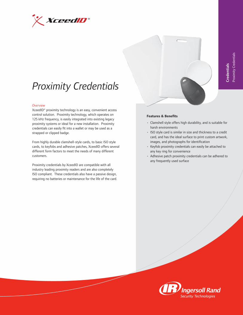
OverviewXceedID® proximity technology is an easy, convenient access control solution. Proximity technology, which operates on 125 kHz frequency, is easily integrated into existing legacy proximity systems or ideal for a new installation. Proximity credentials can easily fit into a wallet or may be used as a strapped or clipped badge.
From highly durable clamshell-style cards, to basic ISO style cards, to keyfobs and adhesive patches, XceedID offers several different form factors to meet the needs of many different customers.
Proximity credentials by XceedID are compatible with all industry leading proximity readers and are also completely ISO compliant. These credentials also have a passive design, requiring no batteries or maintenance for the life of the card.
Proximity Credentials
Features & Benefits
• Clamshell style offers high durability, and is suitable for harsh environments
• ISO style card is similar in size and thickness to a credit card, and has the ideal surface to print custom artwork, images, and photographs for identification
• Keyfob proximity credentials can easily be attached to any key ring for convenience
• Adhesive patch proximity credentials can be adhered to any frequently used surface
Cre
dent
ials
Prox
imity
Cre
dent
ials

877-671-7011 • securitytechnologies.ingersollrand.com ©2012 Ingersoll Rand 005426 02/12
125 kHz Proximity Credentials
Model Number 7410 7510 7610 7710
Credential Type Clamshell ISO-Glossy White1 Keyfob PVC Disk
Credential Technology; ISO Standard 125 kHz Prox
Dimensions (HWT in inches) 3.37x2.125x0.075 3.37x2.125 x0.033 2x1.24 x0.38 35mm
Slot Punch (Printed Guide) Vertical (Punched) Vertical or Horizontal Keyring N/A
Memory Capacity; Application Sectors
N/A
WarrantyLifetime - Credentials have a lifetime warranty against manufacturers defects.
See sales policy for complete warranty details.
1 ISO-Glossy White style credentials are made from composite material, are printable, and can include a magnetic stripe as an option. Add M1 to the model number for a magnetic stripe when ordering.
INGERSOLL RAND, the Ingersoll Rand logo and Schlage are trademarks of Ingersoll-Rand plc, its subsidiaries and/or affiliates in the United States and other countries. All other trademarks are the property of their respective owners.

Bio
met
rics
BiometricsThis section of the Electronic Access Control catalog covers HandKey® biometric hand geometry readers and other accessories that can be easily integrated into an access control system.
Overview
HandKey® biometric hand geometry readers
from Schlage provide increased security for the
most important openings in your facilities. The
HandKey utilizes the size and shape of the hand
to verify the identity of the user, ensuring that
only authorized users can access the door. While
other credentials can be lost, stolen or duplicated
without authorization, the HandKey eliminates this
risk. The open-architecture design of the HandKey
makes integrating biometric hand readers into
critical access points easy, simple, and seamless for
new or existing access control systems.
Features
The HandKey provides the flexibility to be used
as a stand-alone device that protects a single
critical access point, or integrated into virtually
any new or existing access control system in the
market. Standalone operation is enabled utilizing
the built-in door lock output, and a programmable
auxiliary output that can be used to output audible
or silent alarms, or activate lighting systems or
other peripheral devices. The same HandKey reader
can be set up to operate in card reader emulation
mode, outputting Wiegand data to an access
control system. This enables the HandKey to look
just like a card reader to your access control system,
ensuring real-time monitoring and communication
between the device and your access control panel.
Event monitoring alerts you in the event that
the device has been tampered with, when a user
is refused after exceeding the user definable
number of verification attempts, or when the user
is under duress. With the HandKey, you can also
customize security levels, time zones, holidays
and languages based on your unique needs.
Benefits
The HandKey creates an affordable way to
provide the highest level of security possible for
your access control application. Verification of
identity takes less than one second, making it
ideal for even high throughput applications.
The hand reader ensures that you are only allowing
the correct people, not just the proper cards, to
access the most important areas of your facility.
The cost commonly associated with managing an
access control system can be minimized with the
help of a HandKey. Since the credential cannot
be forgotten or stolen, you eliminate the need to
replace lost, damaged, or stolen cards or keys.
The HandKey readers measure the size and
shape of a user’s hand, including length, width,
thickness and surface area, to verify identity.
The HandKey does not read fingerprints or palm
prints, and works effectively even if the user’s
hand is wet, dirty or injured.
Designed upon an open-architecture platform,
the HandKey ensures that you can incorporate
biometrics where you need them, whether it is
on a single high-security door within your facility,
or on many openings throughout your whole
organization as part of an access control system.
Macintosh HD:Users:trighter:Documents:_IngersollRand:EAC_Catalog:005027_Biometics_Intro:005027_Biometrics_Introduction:005027_Biometrics_Introduction_110912.indd January 14, 2013 9:38 AM Page 125

Bio
met
rics
Options
The HandKey Series readers have several options
to choose from including:
• Biometric Reader Model: HandKey-II
• Communications: Ethernet or modem
communications module options to meet the
needs of your communication environment.
• Memory: Field-upgradeable and expandable
memory options to support from 512 to
259,072 users.
• Outdoor Enclosures: To protect the reader
from the elements and enable operations
in a variety of outdoor or other harsh
environments.
• Card Reader and Keypads: A variety of
reader mounted or wall-mounted options,
including proximity, magnetic stripe, barcode,
HID iCLASS® and MIFARE®.
• Mounting Options: Enable mounting on
table-top, surface wall-mount, or recessed
wall-mount.
Accessories
A variety of HandKey accessories are available to
maximize the flexibility of your solution:
• HandNet Lite provides an easy way to
manage hand templates for up to 32
HandKeys.
• HandNet for Windows enables you to control
and monitor a network of HandKey® readers.
With one program you can monitor activity
and alarms on all readers, manage hand
templates between readers, and control the
access of each user. HandNet for Windows
comes in three tiers to enable flexibility based
upon the size of your system. These tiers are
upgradable for added flexibility to meet your
future needs as your application grows.
Macintosh HD:Users:trighter:Documents:_IngersollRand:EAC_Catalog:005027_Biometics_Intro:005027_Biometrics_Introduction:005027_Biometrics_Introduction_110912.indd January 14, 2013 9:38 AM Page 126 Macintosh HD:Users:trighter:Documents:_IngersollRand:EAC_Catalog:005027_Biometics_Intro:005027_Biometrics_Introduction:005027_Biometrics_Introduction_110912.indd January 14, 2013 9:38 AM Page 127

Bio
met
ricsHandKey-II
Construction Polycarbonate housing with aluminum fingerpins
Base Users 512 Users
User Memory Options Expandable to 259,072 users
Template Size 9 bytes
Verification Time Less than one second for comparison to reference template
ID Number Length 1-10 digits
Duress Code 1 leading digit, user definable
Communications
RS232 Baud rate 300 bps to 28,800 bps
RS485 Baud rate 300 bps to 28,800 bps
RS422 Baud rate 300 bps to 28,800 bps
Optional Modem Baud rate 300 bps to 14,400 bps
Optional Ethernet Field Installable: 10 Base T
Mounting Options
Table Mount Option Available
Surface Wall Mount Standard
Recessed Wall Mount N/A
Left Hand Option N/A
Antimicrobial Coating on Platen Standard
Blue Hand Outline Standard
Outdoor and Enclosure Options Heater option available; Polyethylene enclosure with UV resistance available; Metal water tight enclosure available
Dimensions (HxWxD) 11.65 in. x 8.85 in. x 8.55 in.; 29.6 cm x 22.5 cm x 21.7 cm
Power Requirements 12 to 24 VDC or 12 to 24 VAC 50-60 Hz 7 Watts (without options)
Weight 5.3 lbs. (2.4 kgs.) (Without battery back-up or wall plate)
Temperature
Operating 0° C to +45° C /32° F to 113° F
Non-Operating (Storage) -10° C to +60° C /14° F to 140° F
Relative Humidity
Operating 20% to 80% RH Non-condensing
Non-Operating (Storage) 5% to 85% RH Non-condensing
Inputs
Standard 26 bit, 9 bit ID Wiegand
Optional Mag stripe, bar code, smart card
HandKey Inputs Request to Exit, Door switch input, 2 auxiliary inputs
Outputs
Door Control Lock output
Card Reader Emulation Mode Wiegand (standard), mag stripe, bar code
Auxiliary Output 1 programmable auxiliary
Outputs to peripheral devices Audible or silent alarms, door locks, lighting systems
Event Monitoring
Tamper HandKey opened or removed
ID Refused User not verified after user definable number of tries exceeded
Duress User entered duress code digit
Power Failure HandKey switched to optional battery power
Programmable HandKey Commands
Add/remove users; Set global operating thresholds; Set individual user data (authority or threshold levels, time zones); Transmit data from Master to Remote; Data received by Master from Remote; Transmit/receive data from optional software; Check status of door (Tamper, Door monitor switch); Time zones – 62 total (2 fixed, 60 programmable); Set language; Set date format, date and time; Edit holidays
Macintosh HD:Users:trighter:Documents:_IngersollRand:EAC_Catalog:005027_Biometics_Intro:005027_Biometrics_Introduction:005027_Biometrics_Introduction_110912.indd January 14, 2013 9:38 AM Page 126 Macintosh HD:Users:trighter:Documents:_IngersollRand:EAC_Catalog:005027_Biometics_Intro:005027_Biometrics_Introduction:005027_Biometrics_Introduction_110912.indd January 14, 2013 9:38 AM Page 127

Bio
met
rics
877-671-7011 • securitytechnologies.ingersollrand.com ©2012 Ingersoll Rand 005027 11/12
THIS PAGE IS INTENTIONALLY BLANK.
Macintosh HD:Users:trighter:Documents:_IngersollRand:EAC_Catalog:005027_Biometics_Intro:005027_Biometrics_Introduction:005027_Biometrics_Introduction_110912.indd January 14, 2013 9:38 AM Page 128

HandKey® IIPart Number: HK-2-F3
• Convenience of multiple credential options such as proximity, magnetic stripe, barcode, HID iCLASS® and MIFARE®
• Field installable Ethernet module• Outdoor enclosure options that make the HandKey II an ideal
solution for outdoor usage• Field upgradable and expandable memory options from 512
to 259,072 users for scalable security that grows with your needs
• Three user-definable outputs to connect to auxiliary devices such as audible or silent alarms, door locks or lighting systems
• Ability to write the industry’s most compact biometric template on a card instead of in a database results in higher security & unlimited user capacity
• Specially formulated antimicrobial coating with silver ions on the platen to inhibit the growth of bacteria, mold and mildew to mitigate hygiene concerns. The coating is safe and lasts for the life of the product
• Blue hand outline on platen facilitates easy enrollment and reduces error rates during verification
Biometric Access Control ProductsQuick Reference
Bio
met
rics
Bio
met
ric A
cces
s Co
ntro
l Qui
ck R
efer
ence
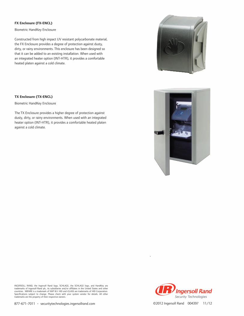
877-671-7011 • securitytechnologies.ingersollrand.com ©2012 Ingersoll Rand 004397 11/12
FX Enclosure (FX-ENCL)
Biometric HandKey Enclosure Constructed from high impact UV resistant polycarbonate material, the FX Enclosure provides a degree of protection against dusty, dirty, or rainy environments. This enclosure has been designed so that it can be added to an existing installation. When used with an integrated heater option (INT-HTR), it provides a comfortable heated platen against a cold climate.
TX Enclosure (TX-ENCL)
Biometric HandKey Enclosure The TX Enclosure provides a higher degree of protection against dusty, dirty, or rainy environments. When used with an integrated heater option (INT-HTR), it provides a comfortable heated platen against a cold climate.
INGERSOLL RAND, the Ingersoll Rand logo, SCHLAGE, the SCHLAGE logo, and HandKey are trademarks of Ingersoll-Rand plc, its subsidiaries and/or affiliates in the United States and other countries. MIFARE is a trademark of NXP B.V. HID and iCLASS are trademarks of HID Corporation. Specifications subject to change. Please check with your system vendor for details. All other trademarks are the property of their respective owners.

HandKey® IIBiometric Hand Geometry Reader
Features and Benefits
• Convenience of multiple credential options such as proximity, magnetic stripe, barcode, HID iCLASS® and MIFARE®
• Field installable Ethernet module • Outdoor enclosure options that make the HandKey II an
ideal solution for outdoor usage • Field upgradable and expandable memory options from
512 to 259,072 users for scalable security that grows with your needs
• Three user-definable outputs to connect to auxiliary devices such as audible or silent alarms, door locks or lighting systems
• Ability to write the industry’s most compact biometric template on a card instead of in a database results in higher security & unlimited user capacity
• Specially formulated antimicrobial coating with silver ions on the platen to inhibit the growth of bacteria, mold and mildew to mitigate hygiene concerns. The coating is safe and lasts for the life of the product
• Blue hand outline on the platen facilitates easy enrollment and reduces error rates during verification
Nothing is tougher!
Our HandKey II product is ideal for applications where consistent and dependable security is of prime importance. The product is easy to maintain, and provides an ideal mix of convenience, security and peace of mind.
Top 10 reasons to select Hand Geometry
FIELD PROVEN RELIABILITY1. Hundreds of thousands of HandKeys are installed all over
the world in diverse applications providing millions of error free transactions every day
CONVENIENCE AND COST SAVINGS2. Incredibly fast installation & intuitive enrollment increases
user convenience3. Verification in less than 1 second makes it ideal for high
throughput applications4. High product quality + Low maintenance costs = Low total
cost of ownership5. Eliminate the worry of lost, stolen or unauthorized transfer
of ID cards plus the cost of purchasing and maintaining these cards
ELIMINATE PRIVACY CONCERNS6. Hand Geometry technology is well accepted by end users as
there are NO fingerprints or palm prints taken and the user does not leave behind any trace of their biometric data
AMAZING VERSATILITY7. HandKeys can be used as standalone systems to protect
critical access points that can be easily integrated into virtually every new or existing access control system in the market today
8. Ability to customize user specific security levels, time zones, holidays and languages based on your needs
9. Optional access control template management software allows the HandKeys to form a system that communicates alarms and transactions in real time, provides activity reports, allows supervised on-site or remote user enrollment and expiring privileges for temporary access
10. Environmental enclosures and integrated heater units make the HandKey an ideal solution for outdoor usage
Bio
met
rics
Han
dKey
® II
Bio
met
ric H
andR
eade
r

Door control and monitoring
Each HandKey II is a complete, integrated door controller providing lock operation, request-for-exit and alarm monitoring. Biometric templates and decision-making capability reside locally, ensuring your doors are always secure and will continue to operate properly even if all communication to the main access control system is lost.
Stand-alone or fully integrated
HandKey readers can be used as a stand-alone unit or as part of an integrated access control system. The units easily integrate into existing systems using the card reader emulation mode. Or, by using the HandNet software for template management, thousands of units can be linked together to form a system that communicates alarms and transactions in real time, provides activity, user and systems reports, and allows supervised user enrollment and deletions at any reader. A variety of communications options, including dial-up modems and Ethernet, allow you to design a system that’s right for your facilities.
In a network
Schlage’s HandNet software links a virtually unlimited number of HandKey units into an integrated door access control system. All alarms and transactions report back in real time to the central computer, making door and alarm monitoring easy and efficient. Activity, user and system reports can be easily generated. The central computer handles all hand template management allowing supervised enrollment at any reader and system wide deletions. An optional internal modem lets you include remote site operations. Ethernet communication is also available.
877-671-7011 • securitytechnologies.ingersollrand.com
Door Switch
PC running HandNetfor Windows
System NetworkRS-485, Ethernet or Modem
Door Switch
DoorLock
DoorLock
DoorLock
Door Switch
Door Switch
Stand-alone operation lets you provide security to a single door at an affordable price
HandKey-II
©2012 Ingersoll Rand 004535 11/12
Base Model HandKey IIDescription HandKey with base memory for 512 users
Verification Time ≤ 1 second for comparison to reference template
ID Number Length 1 – 10 digits
Duress Code 1 leading digit, user definable
Communication RS232: Baud rate 300 bps to 28,800 bpsRS422: Baud rate 300 bps to 28,800 bpsRS485: Baud rate 300 bps to 28,800 bpsOptional Modem: Baud rate 300 bps to 14,400 bpsOptional Ethernet: 10 Base T
Template Size 9 bytes
User Memory 512 users expandable to 259,072 users
Inputs Standard: 26 bit, 9 bit ID Wiegand Optional: Mag stripe, bar code, smart cardHandKey input: Request to Exit, Door switch input, 2 auxiliary inputs
Outputs Door control: Lock outputCard reader emulation mode: Wiegand, mag stripe, bar code 1 programmable auxiliary Outputs to peripheral devices: Audible or silent alarms, door locks, lighting systems
Event Monitoring Tamper: HandKey opened or removedID refused: User not verified after user defin-able number of tries exceededDuress: User entered duress code digit Power failure: HandKey switched to optional battery power
ProgrammableHandKey Commands
• Add / remove users • Set global operating thresholds• Set individual user data (authority or
threshold levels, time zones)• Transmit data from Master to Remote• Data received by Master from Remote• Transmit / receive data from optional software • Check status of door (Tamper, Door monitor
switch)• Time zones – 62 total (2 fixed, 60 programmable)• Set language• Set date format, date and time• Edit holidays
Antimicrobial Available on Platen
Blue Hand Outline Available on Platen
Dimensions HxWxD 11.65 in. x 8.85 in. x 8.55 in.29.6 cm x 22.5 cm x 21.7 cm
Power Requirements 12 to 24 VDC or 12 to 24 VAC 50-60 Hz 7 Watts(without options)
Weight 5.3 lbs. (2.4 kgs.) (Without battery back-up or wall plate)
Temperature Operating: 0 deg C to +45 deg C / 32 deg F to 113 deg FNon-Operating (Storage): -10 deg C to +60 deg C / 14 deg F to 140 deg F
Relative Humidity Operating: 20% to 80% RH Non-condensing Non-operating (Storage): 5% to 85% RH Non-condensing
INGERSOLL RAND, the Ingersoll Rand logo, SCHLAGE, the SCHLAGE logo, and HandKey are trademarks of Ingersoll-Rand plc, its subsidiaries and/or affiliates in the United States and other countries. MIFARE is a trademark of NXP B.V. HID and iCLASS are trademarks of HID Corporation. Specifications subject to change. Please check with your system vendor for details. All other trademarks are the property of their respective owners.

Schlage offers a number of accessories for access control HandReader terminals. From networking options to memory expansions, we’ll help you create the solution to meet your specific needs.
Biometric Terminal Options and Accessoriesfor HandKey®
Bio
met
rics
Han
dKey
® B
iom
etric
Ter
min
al A
cces
sorie
s
Base Model HandKey IICard Readers Prox: Externally top mounted HID prox reader. Factory option only
HID iCLASS®: iCLASS reader,Factory option onlySC-100: MIFARE® reader, Factory option onlyCR-2: Mag stripe wall mount card readerBC-100: Bar code reader, wall mount swipe
Memory EM-801-F3: Field upgradable memory expansion up to 9,728 usersEM-803-F3: Field upgradable memory expansion up to 32,512 usersEM-813-F3: Memory expansion up to 64,768 usersEM-823-F3: Memory expansion up to 129,536 usersEM-833-F3: Memory expansion up to 194,304 usersEM-843-F3: Memory expansion up to 259,072 users
Communication EN-200: Field upgradable Ethernet communication module 10baseTMD-500: Internal Dial-up modem
Power Options PS-110: Power supply, 120VAC to 13.5 VDCPS-220: Power supply, 220VAC to 13.5 VDCBB-250: Optional battery backup
Mounting TM-100: Table top secure mount for flat surfaces
Left Hand Option NA
Network Acces-sories
DC-102: Data converter for 4 wire system, RS-232 to RS-422 with 120V, 60Hz power supplyDC-102 with 220V, 50Hz power supplyDC-104: Data converter for 2 or 4 wire systems, RS232 to RS485/RS 422 with 120V, 60Hz power supplyDC-104 with 220V, 50Hz power supply

©2012 Ingersoll Rand 004400 11/12
[INGERSOLL RAND, the Ingersoll Rand logo, SCHLAGE and the SCHLAGE logo are trademarks of Ingersoll-Rand plc, its subsidiaries and/or affiliates in the United States and other countries. MIFARE is a trademark of NXP B.V. HID and iCLASS are trademarks of HID Corporation. Specifications subject to change. Please check with your system vendor for details. All other trademarks are the property of their respective owners.
THIS PAGE IS INTENTIONALLY BLANK.
877-671-7011 • securitytechnologies.ingersollrand.com

OverviewSchlage biometrics provides various options to protect your HandKeys® from the elements. Two different, proven solutions are available to ensure your HandKeys keep performing regardless of your environment.
FX Enclosure (FX-ENCL)Biometric HandKey Enclosure Constructed from high impact UV resistant polycarbonate material, the FX Enclosure provides a degree of protection against dusty, dirty, or rainy environments. This enclosure has been designed so that it can be added to an existing installation. When used with an integrated heater option (INT-HTR), it provides a comfortable heated platen against a cold climate.
TX Enclosure (TX-ENCL)Biometric HandKey Enclosure The TX Enclosure provides a higher degree of protection against dusty, dirty, or rainy environments. When used with an integrated heater option (INT-HTR), it provides a comfortable heated platen against a cold climate.
Enclosure Optionsfor the HandKey® Series
FX Enclosure
TX EnclosureB
iom
etri
cs
Han
dKey
® En
clos
ure
Opt
ions

877-671-7011 • securitytechnologies.ingersollrand.com ©2012 Ingersoll Rand 004398 11/12
Specifications
FX Enclosure
TX Enclosure
Part Number FX-ENCL TX-ENCL
Temperature Range -20F to 120F / -29C to 49C -45F to 120F / -43C to 49C
Dimensions H x W x D14.75 in x 12.00 in x 10.50 in37.5 cm x 30.5 cm x 26.7 cm
23.00 in x 14.00 in x 11.25 in58.4 cm x 35.6 cm x 28.6 cm
Cross Weight(including reader)
7.3 lbs / 3.3 kg 45.0 lbs / 20.4 kg
HandReader Models HK-2-F3 HK-2-F3
HeaterFactory installed option only,Model No. INT-HTR
Factory installed option only,Model No. INT-HTR
INGERSOLL RAND, the Ingersoll Rand logo, SCHLAGE, the SCHLAGE logo, HandPunch and HandKey are trademarks of Ingersoll-Rand plc, its subsidiaries and/or affiliates in the United States and other countries. Specifications subject to change. Please check with your system vendor for details. All other trademarks are the property of their respective owners.

OverviewHandNet for Windows lets you control and monitor a network of HandKey readers. With just one comprehensive program, you can monitor activity and alarms on all readers, and control the access of each user.
Features and Benefits
• Automatic hand template management feature allows template distribution from an enrollment HandKey to other selected HandKeys thus eliminating the need for a user to be enrolled at every HandReader
• Independent door control capability without the need for an access control panel
• Monitor multiple remote sites from the convenience of your PC
• Remote enrollment feature enables a HandKey to be controlled from the software. For example, a guard behind a glass partition or a supervisor in a distant office can enroll new users without physically going to the HandKey
• Assign temporary access to selected users by specifying a user’s access start and stop days and times
• Manage archive activity to keep old information available for reports
• Manage alarms for additional security
HandNet® for Windows
Bio
met
rics
Han
dNet
® fo
r Win
dow
s

877-671-7011 • securitytechnologies.ingersollrand.com ©2012 Ingersoll Rand 004399 11/12
Specifications HandNet For Windows HandNet Lite
Computer Pentium 233 MHz or higher (Minimum 133 MHz)
Intel 666 MHz or higher
Operating System
Windows XP Professional Service Pack 2Windows XP Professional Service Pack 3Windows Vista Business Service Pack 1Windows 7 Pro Compatible 32 BitWindows 7 Pro Compatible 64 Bit
Windows XP SP3, Vista Business SP1Windows Server 2003 SP1 or greaterWindows 2000 Professional or Server Editions SP4, and Windows 95 & 98
Drive CD ROM for installation CD ROM for installation
Hard Disk 50 MB Minimum, 10 MB Free space 60 GB Minimum, 10 GB Free space
Monitor SVGA Color, 1024 x 768 recommended(800 x 600 minimum)
SVGA Color, 1024 x 768 recommended(800 x 600 minimum)
Memory 32 MB (Minimum 16 MB) 4 Gb (Minimum 2 GB)
Database MS Access MS SQL Server 2000 MSDE
Products SupportedHK-2-F3, ID3D-R / RW
HK-2-F3, ID3D-R/RW, DX-2000, DX-2100, DX-2200, DX-2400
Template Managements Available Available
Supported Communications RS232, RS485, Ethernet, Modem RS232, RS485, Ethernet
RS232, RS485, Ethernet, Modem RS232, RS485, Ethernet
Smart Card Compatability NA HID iCLASS®, MIFARE®, MIFARE DESFire™ EV1
Time Zones Available Available
Reports Available Limited – use reports from an access control panel
Door Control Available NA – use panel door control
Alarms Available NA – use panel alarms
Open Door Remotely Available NA – use panel door control
Network Readers Available Available
Archive Activity Available Available – database backup
Remote Enrollment Available Available
OPTIONS
HN-2-T1 Manages up to 5 HandKeys
HN-2-T2 Manages up to 25 HandKeys
HN-2-T3 Manages an UNLIMITED number of HandKeys
HandNet Lite Software program to manage up to 32 HandKeys
INGERSOLL RAND, the Ingersoll Rand logo, SCHLAGE, the SCHLAGE logo and HandKey are trademarks of Ingersoll-Rand plc, its subsidiaries and/or affiliates in the United States and other countries. MIFARE and MIFARE DESFire EV1 are trademarks of NXP B.V. HID and iCLASS are trademarks of HID Corporation. Specifications subject to change. Please check with your system vendor for details. All other trademarks are the property of their respective owners.

OverviewSchlage biometrics offers training courses to provide you with the tools and services needed to optimize the performance and reliability of the HandKey® and related software solutions. Our comprehensive offering will help reacquaint you with HandKey hardware, installation, and its relationship with software operation. Training is regularly scheduled at our factory location or can be delivered at your location.
The HandKey Training Course Covers: • Introduction to Biometrics • Installation • Access Control Product Line • Hands-on Training • Options & Accessories • Troubleshooting
The Access Control HandKey Software Training Course Covers: • Comparison of HandNet® for Windows vs. HandNet Lite • Overview of HandNet for Windows & HandNet Lite • Installing HandNet for Windows & HandNet Lite • Adding Users • Connecting to the HandKey • Creating Reports • Archiving • Database Backup and Restore • Troubleshooting
Training Courses
Keeping installers, technicians, and sales people current on the HandKey features, capabilities, troubleshooting techniques, and installation guidelines is key to profitability and maintaining customer satisfaction.
The goals of these courses are to provide a working knowledge of the HandKey hardware and software and be able to perform basic troubleshooting. The Schlage HandKey training classes are technically oriented and feature hands-on training through classroom exercises.
Biometrics for Access ControlTraining Course Outline
Schlage Biometrics ACCESS CONTROL Training Courses
SBT-HK 1-Day Schlage Biometrics Training - HandKey
SBT-HNWL 1-Day Schlage Biometrics HandNet for Windows & HandNet Lite Software Training
Bio
met
rics
Bio
met
rics
Trai
ning
Cou
rse
Out
line

877-671-7011 • securitytechnologies.ingersollrand.com ©2012 Ingersoll Rand 002872 11/12
THIS PAGE IS INTENTIONALLY BLANK.
INGERSOLL RAND, the Ingersoll Rand logo, SCHLAGE, the SCHLAGE logo, HandKey and HandNet are trademarks of Ingersoll-Rand plc, its subsidiaries and/or affiliates in the United States and other countries. All other trademarks are the property of their respective owners.
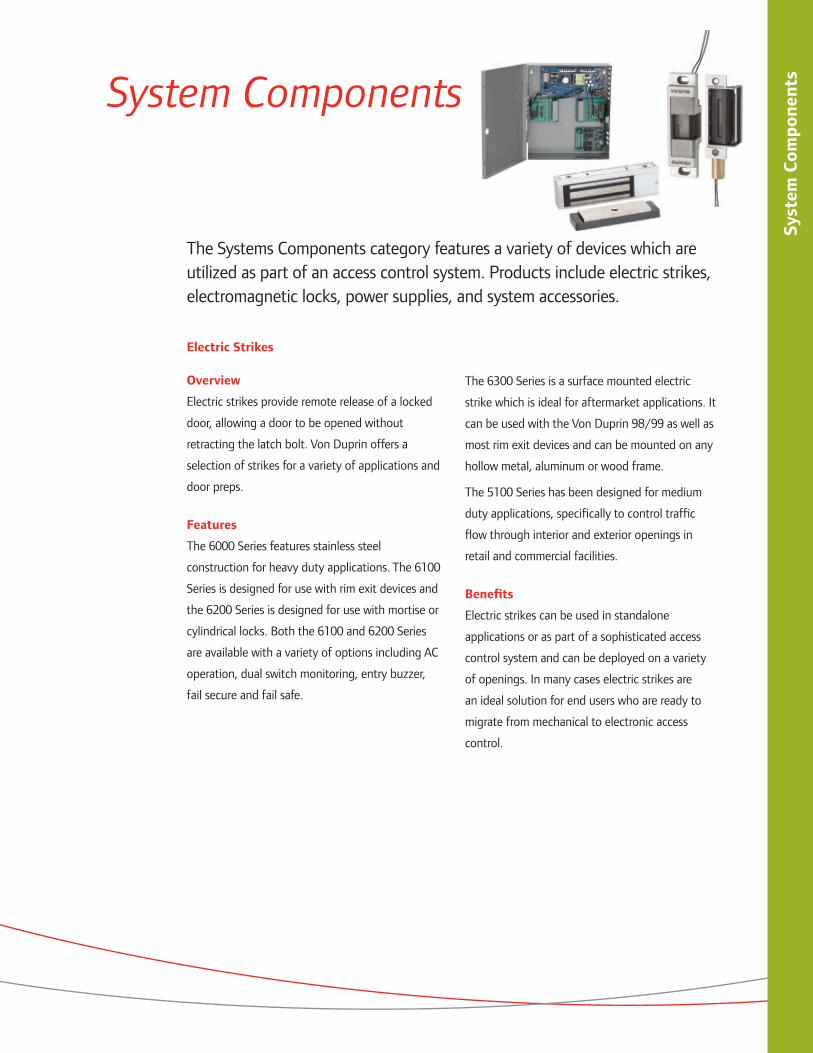
Syst
em C
ompo
nent
s
System Components
The Systems Components category features a variety of devices which are utilized as part of an access control system. Products include electric strikes, electromagnetic locks, power supplies, and system accessories.
Electric Strikes
Overview
Electric strikes provide remote release of a locked
door, allowing a door to be opened without
retracting the latch bolt. Von Duprin offers a
selection of strikes for a variety of applications and
door preps.
Features
The 6000 Series features stainless steel
construction for heavy duty applications. The 6100
Series is designed for use with rim exit devices and
the 6200 Series is designed for use with mortise or
cylindrical locks. Both the 6100 and 6200 Series
are available with a variety of options including AC
operation, dual switch monitoring, entry buzzer,
fail secure and fail safe.
The 6300 Series is a surface mounted electric
strike which is ideal for aftermarket applications. It
can be used with the Von Duprin 98/99 as well as
most rim exit devices and can be mounted on any
hollow metal, aluminum or wood frame.
The 5100 Series has been designed for medium
duty applications, specifically to control traffic
flow through interior and exterior openings in
retail and commercial facilities.
Benefits
Electric strikes can be used in standalone
applications or as part of a sophisticated access
control system and can be deployed on a variety
of openings. In many cases electric strikes are
an ideal solution for end users who are ready to
migrate from mechanical to electronic access
control.

Syst
em C
ompo
nent
s
Electromagnetic Locks
Overview
Schlage offers a broad selection of
electromagnetic locks – with feature and
function sets to address a variety of applications.
Whether it’s securing a hospital laboratory,
monitoring a controlled area in an airport or
providing traffic control for doors in a commercial
or education building, Schlage electromagnetic
locks are designed to exceed the standards
set by the Builders Hardware Manufacturers
Association (BHMA).
Features
The newly designed M400 Series
electromagnetic locks are available in two
configurations to meet your specific security
needs. The M420/450/490 provides basic
security while the M420P/450P/490P provides
intelligent sensing and reporting features needed
to integrate with access control systems. The
M400 Series is available with BHMA hold force
ratings of 500 lbs, 1000 lbs and 1500 lbs.
For retrofit applications, the 40 Series and 70
Series electromagnetic locks are fully featured
and cost effective. The 40 Series is rated to 500
lbs and the 70 Series is rated to 1000 lbs of hold
force.
Schlage offers a variety of electromagnetic locks
for specialty applications including the M490DE
for delayed egress, 490G for gates, GF3000 shear
locks for mortised/vertical doors, and the 320M
for sliding door applications.
Benefits
The M400 Series electromagnetic locks were
redesigned with a new bayonet mounting feature
that allows the installer to have their hands free
during the mounting process. The M400 Series
electromagnetic locks are non-handed and
symmetrical, allowing for optimum placement of
the magnet no matter the application.
The 40 and 70 Series Electromagnetic
locks feature common templates for cost
effective retrofit installations. The specialty
electromagnetic locks are designed with specific
feature sets which optimize performance
in a variety of unique, harsh and complex
environments.

Syst
em C
ompo
nent
s
Power Supplies
Overview
The PS900 Series is a consolidated line of power
supplies and accessories that offer enhanced
flexibility and functionality specific to the
changing needs of the access control market.
The PS900 Series can be used in a variety of
applications to convert high voltage AC power
into the low voltage DC outputs required by most
access control devices. The PS900 Series protects
devices downstream by providing Class 2*, filtered
and regulated power. The full line is UL 294
certified.
Features
The PS900 Series features three Schlage
branded models; PS902 - 2 amp, PS904 - 4
amp and PS906 – 6 amp. The PS900 Series also
features the Von Duprin PS914 – 4 amp with
high in-rush which is designed specifically for
use with electrified exit devices. These PS900
Series power supplies can be outfitted with a
variety of distribution options including basic
fuse protection, simple relay, and advanced
logic providing complex sequencing and timing
functions.
Benefits
Common to the line of PS900 Series power
supplies is a constant output rating at both 12v
and 24v settings, universal 120 VAC to 240 VAC
input, and polarized option board connectors.
New fire alarm interface board mounting allows
outputs to be configured as switched (power cut)
or unswitched (power continues) when signal
provided.
Installation is simplified by utilizing a flat
mounting design and polarized locking connectors
for option boards. This new design eliminates
the need for racks and side connectors. The flat
mounting of the option boards also provides for
easier access to the terminal blocks for connection
of electrified devices (such as electrified strikes,
electromagnetic locks, card readers, etc).
*Note: PS906 can provide Class 2 rated outputs when used with 900-8P distribution board.

Syst
em C
ompo
nent
s
System Accessories
Overview
System Accessories include a variety of devices
that enable specific functionality whether in
standalone applications or as part of networked
access control systems. The category is comprised
of pushbuttons, key switches, request to exit
bars, monitoring stations & consoles, exit sensors,
electric horns and more.
Features
The specially designed 620 Series heavy-duty
pushbuttons and 700 Series general purpose
pushbuttons, as well as the 650 Series heavy-
duty keyswitches, offer momentary or maintained
SPDT or DPDT contact configurations.
The 700 Series Pushbuttons are used to control
the ingress and/or egress of a door.
The 620 to 631 Series are heavy duty and have
multiple button configurations and finish options.
The 650 Series keyswitches utilize an innovative
magnetic spring design which allows installers to
configure both clockwise and counterclockwise
key turn direction as well as momentary or
maintained action in seconds.
The 740 Series Emergency Break Glass Releases
are designed for use as emergency releases of
non-designated egress doors such as in individual
and partitioned laboratories, secluded testing
areas, or other isolated work rooms that are
purposely provided with exit doors.
The 672/692 Series Request-to-Exit Bars are
non-latching releasing devices which allow egress
at doors with electric locking devices, such as
electromagnetic locks. The SCAN II is a passive
infrared (PIR) sensor specifically designed for
request-to-exit applications.
The 8200 Series consoles provide door control
and monitoring for up to eight zones. The 8204 is
used for one to four zones and the 8208 for one
to eight zones.
The 800 Series monitoring stations can provide
monitoring for a single zone with up to 2 LED
indicators. The 801 unit includes an audible and
visual indication of lock status and delay activation.
The 660 Series Mini Station Control is designed
for concealed desk application, and it is used to
release an electric or electronic locking mechanism
from a remote location.
Electric horns are designed for use as an
immediate local audible warning device
incorporated in a security system. Horns are 12
or 24VDC, field selectable and have eight sound
tones up to 3000Hz.
Magnetic door position switches can be used to
monitor a wide range of conditions for doors, roof
hatches, gates or the proximity of any two objects.
Armored door cords are used when installing
electric exit devices or electric locks and provide
a simple and economical solution for transferring
power from frame to door.
The PB405 PowerBolt is a mortise, right angle
deadbolt with which is available with fail safe or
fail secure options.
Benefits
System accessories allow you to customize each
opening to meet specific security and safety
needs. Schlage offers a variety of the most
popular accessories designed for medium to
heavy duty applications. By choosing Schlage
components you can be assured that the system
will meet the requirements of the job, whether
new construction or aftermarket.

Syst
em C
ompo
nent
s
Schlage Power Supplies Von Duprin Supplies
PS902 PS904 PS906 PS914
Features Input Voltage 120V/240V AC, 50/60 Hz, universal input
Output Voltage 2 amp @ 12V or 24V DC, field selectable with
jumper, 240m Vpp max ripple,
5% regulation
4 amp @ 12V or 24V DC, field selectable with
jumper, 240m Vpp max ripple,
5% regulation
6 amp @ 12V or 24V DC, field selectable with
jumper, 240m Vpp max ripple,
5% regulation
4 amp, High Inrush @ 12V or 24V DC,
field selectable with jumper,
360m Vpp max ripple, 5% regulation
AC Primary Fuse Size 3.15A, 250V, 5 x 20mm SLOW-BLOW
4A, 250V, 5 x 20mm SLOW-BLOW
6.3A, 250V, 5 x 20mm SLOW-BLOW
6.3A, 250V, 5 x 20mm SLOW-BLOW
Battery Fuse Size 7.5A 32V ATO Blade Style
DC Output Protection Overload Protection - current limited foldback circuit
AC Input Termination 3 position terminal block with protective cover; wire capacity 10 AWG max
DC Output Termination 2 position terminal block with protective cover; wire capacity 12 AWG max
Operating Temperature 32 - 120°F (0 -49°C)
Distribution/Option Board Connectors 1 2 3 2
Fire Alarm Board Connector Yes No No No
Enclosure:
Fire Alarm Board Connector 14 in. (h) x 12 in. (w) x 4 in. (d)
Operating Temperature 32˚F - 120˚F (0˚C - 49˚C)
Option Boards:
900-BB: Battery Backup Y Y Y Y
900-BBK: Battery Backup Kit Y Y Y Y
900-FA: Fire Alarm Y Y (Must be installed on distribution boards)
Y (Must be installed on distribution boards)
Y (Must be installed on distribution boards)
900-2RS: 2 Relay EL Control Board Y
900-2Q: 2 Relay QEL Control Board Y Y Y Y
900-4R: 4 Relay Output Board Y Y Y Y
900-4RL: 4 Relay Logic Board Y Y Y Y
900-8F: Fused 8 Zone Distribution Board Y Y Y Y
900-8P: PTC 8 Zone Distribution Board Y Y Y Y
Certifications
UL294 Y Y Y Y
Class 2 Y Y Y Y
RoHS Y Y Y* Y
FCC Part 15 Y Y Y Y
*Note: Class 2 rated outputs can be provided using 900-8P distribution board in conjunction with the PS906.

Syst
em C
ompo
nent
s
M400 High Security Mag Locks
M420 M420P M450 M450P M490 M490P M490DE M490DEP M490G
Features
Hold Force 500 lbs. 1000 lbs 1500 lbs 1500 lbs 1500 lbs
Input Voltage 12V/24V DC 12V/24V DC 12V/24V DC 12V/24V DC 12V/24V DC
Current Draw0.75A @ 12V DC 0.38A @ 24V DC
0.75A @ 12V DC 0.38A @ 24V DC
0.65A @ 12V DC 0.35A @ 24V DC
.75A @ 12V DC
.45A @ 24V DC0.65A @ 12V DC 0.35A @ 24V DC
Features
Automatic Voltage Sensor (AVS) Y Y Y Y Y
Voltage Suppression Y Y Y Y Y
Internal Plunger Switch - - - Y -
Auto Relocking Switch (ARS) - - - - -
Magnetic Bond Sensor (MBS) - Y - Y - Y - Y Y
Door/Gate Status Monitoring (DPS/DSM) - Y - Y - Y - Y Y
Relock Time Delay - Y - Y - Y - Y -
Anti-Tamper Switch (ATS) - O - O - O - O -
MBS Indicator (LED) - O - O - O - O -
Anti-Tailgate Feature - - - Y - -
Surface Mount Y Y Y Y -
Mortise Mount - - - - -
Top Jam (inswinging doors) O O O - -
Herculite Door Bracket O O O O -
Bayonet Mounting Bracket Y Y Y Y -
Universal Mounting Bracket - - - - Y
Field Configurable Handing Y Y Y Y -
Lock Dimensions (H xW x L)2.5 in. x 9 in. x 1.375 in.
3 in. x 10.25 in. x 1.75 in.
3 in. x 12.5 in. x 1.75 in.
3 in. x 12.5 in. x 3.0625 in.
3 in. x 11 in. x 1.75 in.
Weight 6 lbs 10 lbs 14 lbs 16 lbs 14 lbs
Certifications
BHMA Grade 1 Y Y Y Y -
UL1034 Y Y Y -
Ul10C 3HR 3HR 3HR 3HR -
cUL Y Y Y Y -
CSFM Pending Pending Pending Pending -
NFPA101 - - - Y -
BOCA - - - Y -

Syst
em C
ompo
nent
s
Specialty Mag Locks 40/70 Standard Duty Mag Locks
GF3000SM (Surface Mount)
GF3000 (Mortise Mount)
320M 40 70
Features
Hold Force 3000 lbs 500 lbs 500 lbs 1000 lbs
Input Voltage 12V/24V DC 12V/24V DC 12V/24V DC 12V/24V DC
Current Draw0.90A @ 12V DC 0.45A @ 24V DC
0.23A @12V DC 0.45A @ 24V DC
0.32A @ 12V DC 0.15A @ 24V DC
0.25A @12V DC 0.12A @ 24V DC
Features
Automatic Voltage Sensor (AVS) Y Y Y Y
Voltage Suppression Y Y Y Y
Internal Plunger Switch - - - -
Auto Relocking Switch (ARS) S - - -
Magnetic Bond Sensor (MBS) O Y Y Y
Door/Gate Status Monitoring (DPS/DSM) O Y Y Y
Relock Time Delay Y Y - -
Anti-Tamper Switch (ATS) - - - - -
MBS Indicator (LED) - - - - -
Anti-Tailgate Feature - - - - -
Surface Mount Y - - Y Y
Mortise Mount - Y Y - -
Top Jam (inswinging doors) Y - - O O
Herculite Door Bracket - - - - -
Bayonet Mounting Bracket - - - - -
Universal Mounting Bracket - - - - -
Field Configurable Handing - - - - -
Lock Dimensions (H x W x L)1.25 in. X 9.8125 in.
X 1.5 in.1.5 in. X 9.5 in.
X 1.5 in.1.375 in. x 7 in.
x 1.875 in.1.875 in. x 8 in.
x 1625 in.3 in. x 8 in. x 1.875 in.
Weight 9 lbs. 7 lbs. 6 lbs. 8 lbs.
Certifications
BHMA Grade 1 Y Y Y Y
UL1034 - Y Y Y
Ul10C 3HR 3HR 1HR 1HR
cUL Y Y Y Y
CSFM Y Y Y Y
NFPA101 - - - -
BOCA - - - -

877-671-7011 • securitytechnologies.ingersollrand.com ©2011 Ingersoll Rand 005028 12/11
THIS PAGE IS INTENTIONALLY BLANK.

OverviewVon Duprin electric strikes are known for their reliability, durability and security. The 6100 Series is designed to withstand abuse. Its heavy duty stainless steel construction is fully UL1034 and UL10C listed and ANSI/BHMA Grade 1 1500 lb. hold force rated.
6100 Series electric strikes are designed for use with a variety of Rim Exit Devices. They interface with the latch mechanism of the exit device. The movable lip (keeper) allows a door to open even when the latch bolt is extended. This feature, called remote release provides added benefits such as increased convenience and efficiency. The 6100 Series also provides added security and traffic control.
6100 Series electric strikes can be used for retrofit applications or new construction. To assure the proper selection of an electric strike on new applications, lockset compatibility charts are shown on the next page. When using a lockset not listed or when retrofitting a strike to an existing application, please contact Von Duprin Technical Support for application assistance.
The power failure mode of the 6100 can be specified at the time of order. Fail secure is available for fire rated openings. In a fail secure application the door is normally locked. To unlock the door power must be applied. Fail safe strikes which are commonly used for life safety applications are non-fire rated. To unlock a fail safe strike power is removed. The 6100 comes standard 24 VDC; 12 VDC and AC operation are optional.
Features and Benefits
• Non-handed design provides greater flexibility • Strike box is adjustable to compensate for misalignment of the door or frame
• Two piece plug connectors are furnished for ease of installation and for removal during strike servicing
• ANSI 156.5 Grade 1 1500 lb. hold force rated • UL1034 Burglary-Resistant & UL10C Electric Strike for Fire Door
• Six finishes available to suite with existing hardware • Durable stainless steel construction • 24 VDC standard with 12 VDC and AC operation optional
Syst
em C
ompo
nent
s
6100
Ser
ies
Elec
tric
Str
ikes
6100 SeriesStrikes for Rim Exit DevicesModels 6111, 6112, 6113 & 6121
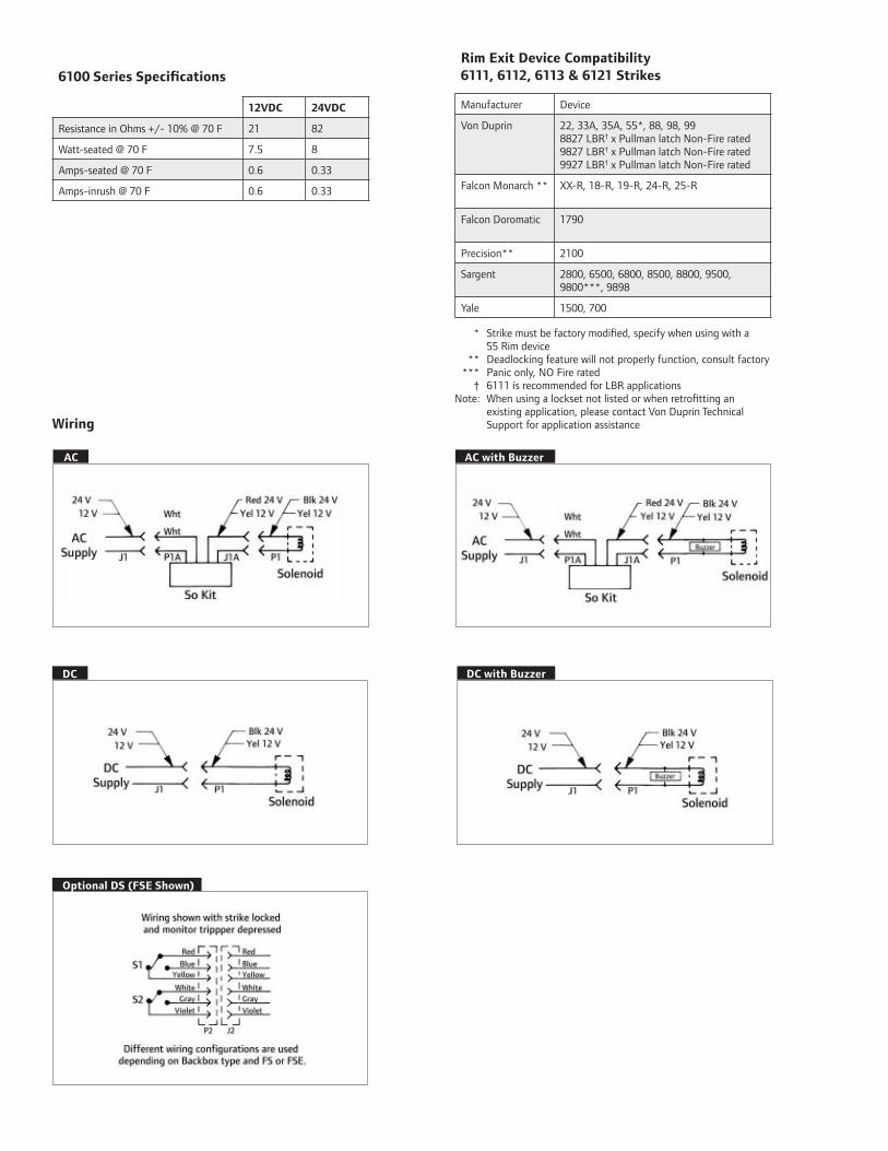
6100 Series Specifications
12VDC 24VDC
Resistance in Ohms +/- 10% @ 70 F 21 82
Watt-seated @ 70 F 7.5 8
Amps-seated @ 70 F 0.6 0.33
Amps-inrush @ 70 F 0.6 0.33
Rim Exit Device Compatibility6111, 6112, 6113 & 6121 Strikes
Manufacturer Device
Von Duprin 22, 33A, 35A, 55*, 88, 98, 998827 LBR† x Pullman latch Non-Fire rated9827 LBR† x Pullman latch Non-Fire rated9927 LBR† x Pullman latch Non-Fire rated
Falcon Monarch ** XX-R, 18-R, 19-R, 24-R, 25-R
Falcon Doromatic 1790
Precision** 2100
Sargent 2800, 6500, 6800, 8500, 8800, 9500, 9800***, 9898
Yale 1500, 700
* Strike must be factory modified, specify when using with a 55 Rim device ** Deadlocking feature will not properly function, consult factory *** Panic only, NO Fire rated † 6111 is recommended for LBR applicationsNote: When using a lockset not listed or when retrofitting an existing application, please contact Von Duprin Technical Support for application assistanceWiring
AC AC with Buzzer
DC with BuzzerDC
Optional DS (FSE Shown)

Model # 6111 6112 6113 6121
Retrofits Model VD 3031 FA 310-4 VD 3011 or 3021 FA 310-4-100
Latchbolt Throw 3/4 ”
Face Plate Length 6” 9” 6” 9 1/8 ”
Backbox Depth 1 3/4 ” 1 3/4 ” 1 15/16 ” N/A
Lockset Rim Exit Device
# DoorsSingle, Double Door with
MullionSingle
Double Door without Mullion
Door/Frame Type Hollow Metal, Aluminum & Wood
Options
Blade Stop Shim Yes No Yes No
DS or DS-LC (Dual Monitor Switches)
Yes
EB (Entry Buzzer - Fail Secure Only)
Yes
Certifications UL1034, UL10C, ANSI/BHMA 156.5 Grade 1 1500 lb. Hold force rated
Application Notes For use with rim exit devices on single doors or double doors with mullion ap-plications. 1/2“ projection Blade Stop Shim 010055-XX available for use on cased opening or blade stop frames. Specify when using 55 rim devices. May also be used with Vertical Rod exit devices noted on previous page x Pullman latch LBR Non-fired rated.
For use with rim exit devices on single door applications. Designed to replace Folger Adam 310-4, minor fame prep modification required.
1/2“ projection Blade Stop Shim 010055-XX available for use on cased opening or blade stop frames. Non-Fire rated.
Non-fire rated. For use with rim exit devices on double door applications without mullion. Strike mounts on inactive leaf. Replace Folger Adam 310-4-100.
Note: 16 VDC and 28 VDC solenoid are sold as replacement parts for existing strikes. Please contact Customer Care for details.
Model Specifications
Dimensions
6111
6"(152mm)
1 5/8"(41mm)
7/8"(22mm)
1/2"(13mm)
2 3/16"(56mm)
1 3/8"(35mm)
13/16"(21mm)
1 5/8"(41mm)
4 1/2"(114mm)
Minimum Clearance
6112
7/8"(22mm)
6"(152mm)
1 5/8"(41mm)
Minimum Clearance
7/8"(22mm)
9/16"(14mm)
1 15/16"(49mm)
4 1/2"(114mm)
1 3/8"(35mm)
2 1/4"(57mm)
7/8"(22mm)
1 5/8"(41mm)
2 1/2"(64mm)
9 1/8"(232mm)
1 5/8"(41mm)
9"(229mm)
7/8"(22mm)
3/4"(19mm)
2 9/16"(65mm)
Minimum Clearance 9/16"
(14mm)
4 1/2"(114mm)
1 5/8"(41mm)
1 11/16"(43mm)
6113
6121

877-671-7011 • securitytechnologies.ingersollrand.com ©2012 Ingersoll Rand 005282 04/12
INGERSOLL RAND, the Ingersoll Rand logo, Von Duprin, the Von Duprin logo and Falcon are trademarks of Ingersoll-Rand plc, its subsidiaries and/or affiliates in the United States and other countries. Precision is a trademark of Stanley Black & Decker. Sargent is a trademark of Sargent Manufacturing Company. Yale is a trademark of Yale Security, Inc.
Ordering Information
6112 FSE DS 24 S024 US3 EB
Mod
el
Pow
er F
ailu
re
Mod
e
Dua
l Sw
itch
*
Vol
tage
Rec
tifi
er K
it*
Fini
sh
Buz
zer*
1 2 3 4 5 6 7
*Optional
– – – – – – – – –
Selections Correspond With the Numbers Above
2 Power Failure ModeFSE Fail Secure. Requires power to be applied
to unlock the strike lip. On loss of power, the strike lip is locked. Fire rated.
FS Fail Safe. Requires power to be applied to lock the strike lip. On loss of power, the strike lip is unlocked. Non-Fire Rated.
4 Voltage (VDC)24 Low voltage DC power12 Low voltage DC powerIf AC power is required specify rectifier kit below.
1 Model6111 See chart on page 3 to make the proper
selection6112 See chart on page 3 to make the proper
selection6113 See chart on page 3 to make the proper
selection6121 See chart on page 3 to make the proper
selection
3 Dual Switch (Optional)DS Monitors latch bolt & lock status. DS
Switches rated at 24 VDC 50 milliampere - 2 Amps.
DS-LC Optional for computer monitoring. Monitors latch bolt & lock status. DS switches rated 24 VDC 50 milliampere or less.
5 Rectifier Kit (Optional)SO12 Converts 12 VAC voltage to 12 VDC to
operate the solenoidS024 Converts 24 VAC voltage to 24 VDC to
operate the solenoid
6 Finish US Number/Von Duprin NumberUS3/85 Plated Polished Brass on Stainless SteelUS4/84 Plated Dull Brass on Stainless SteelUS10/06 Plated Dull Bronze on Stainless SteelUS10B/86 Plated Dark Bronze on Stainless SteelUS32/31 Stainless Steel, PolishedUS32D/32 Stainless Steel, Satin
7 Buzzer (Optional)EB Entry Buzzer. Only available if Fail Secure
(FSE) is specified.

OverviewVon Duprin electric strikes are known for their reliability, durability and security. The 6200 Series is designed to withstand abuse. Its heavy duty stainless steel construction is fully UL1034 and UL10C listed and ANSI/BHMA Grade 1 1500lb. hold force rated.
6200 Series electric strikes are designed for use with a variety of mortise or cylindrical locksets as well as mortise exit devices. It interfaces with the latch mechanism of the exit device. The 6200 Series movable lip (keeper) allows a door to open even when the latch bolt is extended. This feature, called remote release provides added benefits such as increased convenience and efficiency. The 6200 Series also provides added security and traffic control.
6200 Series electric strikes can be used for retrofit applications or new construction. To assure the proper selection of an electric strike on new applications, lockset compatibility charts are shown on the next page. When using a lockset not listed or when retrofitting a strike to an existing application, please contact Von Duprin Technical Support for application assistance.
The power failure mode of the 6200 Series can be specified at the time of order. Fail secure is available for fire rated openings. In a fail secure application the door is normally locked. To unlock the door power must be applied. Fail safe strikes which are commonly used for life safety applications are non-fire rated. To unlock a fail safe strike power is removed. The 6200 Series comes standard with 24 VDC; 12 VDC and AC operation are optional.
Features and Benefits
• Non handed design provides greater flexibility • Strike box is adjustable to compensate for misalignment of the door or frame
• Two piece plug connectors are furnished for ease of installation and for removal during strike servicing.
• ANSI 156.5 Grade 1 1500lb. hold force rated • UL1034 Burglary-Resistant & UL10C Electric Strike for Fire Door
• Six finishes available to suite with existing hardware • Durable stainless steel construction • 24 VDC standard with 12 VDC and AC operation optional
Syst
em C
ompo
nent
s
6200
Ser
ies
Elec
tric
Str
ikes
6200 SeriesStrikes for Mortise or Cylindrical DevicesModels 6210, 6211, 6211AL, 6211WF, 6212, 6212WF, 6213, 6214, 6215, 6216, 6221, 6222, 6223, 6224, 6224AL, 6225 & 6226

6200 Series Specifications12VDC 24VDC
Resistance in Ohms +/- 10% @ 70 F 21 82
Watt-seated @ 70 F 7.5 8
Amps-seated @ 70 F 0.6 0.33
Amps-inrush @ 70 F 0.6 0.33
Mortise Lockset Compatibility6211, 6211AL, 6211WF, 6212, 6213, 6214, 6215, 6221, 6222, 6223, 6224, 6224AL, 6225 & 6226 Strikes
Manufacturer Model Number
Von Duprin 7500
Adams Rite 4510, 4710
Baldwin 6000
Best 24H, 30H
Corbin 9000
Falcon M2300, M2500, M2600, M3300, M3500, M3600
Precision Mortise
Russwin Mortise
Sargent 7700, 8100, 9000
Schlage L9000, K30, K40, K50, K60
Yale 7030, 7130, 8600, 8700
Note: Von Duprin cannot guarantee compatibility as other manufacturer’s designs may change without notice.
Wiring
AC
AC with Buzzer
DC with Buzzer
Optional DS (FSE Shown)
DC
Cylindrical Lockset Compatibility6211, 6211AL, 6211WF, 6212, 6213, 6214, 6215, 6221, 6222, 6223, 6224, 6224AL, 6225 & 6226 Strikes
Manufacturer Cylindrical Latchbolt Projection
Baldwin 1⁄2˝ – 3⁄4˝ (13mm – 19mm)
Best 3⁄8˝ – 3⁄4˝ (10mm – 19mm)
Corbin 1⁄2˝ – 3⁄4˝ (13mm – 19mm)
Falcon 1⁄2˝ – 3⁄4˝ (13mm – 19mm)
Russwin 1⁄2˝ – 3⁄4˝ (13mm – 19mm)
Sargent 1⁄2˝ – 3⁄4˝ (13mm – 19mm)
Schlage 3⁄8˝ – 3⁄4˝ (10mm – 19mm)
Yale 1⁄2˝ – 3⁄4˝ (13mm – 19mm)
Note: Signalling may not function when using 3⁄8” (10mm) throw bolt. Deadlocking cannot be guaranteed with all locks.
Mortise Lockset Compatibility6210
Manufacturer Model Number
Von Duprin 7500
Best 30H (Not 45H/47H)
Corbin/Russwin ML2200, 5000, 9000, CR2200 (Not 2000)
Falcon M100, M200, M300, M400, M500, M600
Sargent 7700, 8100 (Not 7800/8200)
Schlage L9000
Yale 8700 (Not 8800)
Note: When using a lockset not listed or when retrofitting a strike to an existing application, please contact Von Duprin Technical Support for assistance.

Model Specifications
Model # 6210 6211 6211AL 6211WF 6212
Retrofits Model n/a VD 3140, FA 712 FA 722 FA 732 VD 3146
Latchbolt Throw 3/4 ” 3/4 ” 3/4 ” 3/4 ” 3/4 ”
Face Plate Length 4 7/8 ” 4 7/8 ” 4 7/8 ” 4 7/8 ” 6 3/8 ”
Backbox Depth 1 21/32” 1 21/32” 1 21/32” 4 1/2 ” 1 21/32”
LocksetMortise
Cylindrical
# DoorsSingle
Pair
Door & Frame Type
Hollow Metal
Aluminum
Wood
Options
DS or DS-LC (Dual Monitor Switches)
EB (Entry Buzzer - Fail Secure Only)
28 VDC AC rectifier kit
16 VDC solenoid
Certifications
UL1034
UL10C
ANSI/BHMA 156.5 Grade 1 1500lb. Hold force rated
Application Notes 1 2 3 4 5
Application Notes
1 For use with mortise locks without deadbolt on single door, hollow metal frame applications and using ANSI prep at standard height. Strike pocket inserts are provided to accommodate different manufacturers deadlock-ing trigger locations.
2 For use on new installations with mortise locks without deadbolt or cylindrical locks on single door, hollow metal frame applications. Designed to replace Von Duprin 3140 or Folger Adam 712.
3 For use on new installations with mortise locks without deadbolt or cylindrical locks on single door, aluminum frame applications
4 For use on new installations with mortise locks without deadbolt or cylindrical locks on single door wood frame applications. Designed to replace Folger Adams 732. Wood frame horizontal solenoid location differs from Folger Adams. Requires additional frame prep when retrofitting.
5 For use with mortise locks without deadbolt or cylindrical locks on single door, hollow metal or aluminum frame applications. Fits modified ANSI 115.2 cutout. Designed to replace Von Duprin 3146

Model Specifications
Model # 6212WF 6213 6214 6215 6216 6221
Retrofits Model n/aVD 3041, 3042,
3061, 3062FA 310-2 3/4 FA 310-2 FA 310-3-1 VD 3071 & 3072
Latchbolt Throw 3/4 ” 3/4 ” 3/4 ” 3/4 ” 3/4 ” 3/4 ”
Face Plate Length 6 3/8 ” 6” 9” 9” 9” 6”
Backbox Depth 4 3/4 ” 2 1/2 ” 1 5/8 ” 1 5/8 ” 3 5/32” 4 3/4 ”
Lockset
Mortise
Cylindrical
# DoorsSingle
Pair
Door & Frame Type
Hollow Metal
Aluminum †
Wood See note 7 below
Options
DS or DS-LC (Dual Monitor Switches)
EB (Entry Buzzer - Fail Secure Only)
28VDC AC rectifier kit
16VDC solenoid
Certifications
UL1034
UL10C
ANSI/BHMA 156.5 Grade 1 1500lb. Hold force rated
Application Notes 6 7 8 9 10 11
Application Notes
6 For use with mortise locks without deadbolt or cylindrical locks on single door, wood frame applications.
7 For use with mortise locks without deadbolt or cylindrical locks on single door hollow metal or aluminum frame applications (includes wood frame on retrofit applications). Designed to replace Von Duprin 3041, 3042, 3061 and 3062.
8 For use with mortise locks without deadbolt or cylindrical locks on sing door hollow metal or aluminum frame applications. Designed to replace Folger Adams 310-2 3/4
9 For use with mortise locks without deadbolt or cylindrical locks on single door hollow metal or aluminum frame applications. Designed to replace Folger Adams 310-2.
10 For use with mortise locks with deadbolt 1” throw on single door hollow metal aluminum or wood frame applications. Deadbolt must be manually operated. Designed to replace Folger Adams 310-3-1.
11 Open back electric strike for use with mortise locks without deadbolt or cylindrical locks on 1 3/4” (44mm)
thick double door applications. 4 3/4” (120 mm) minimum stile required. For a concealed vertical rod and
mortise device combination, specify “A” backbox.
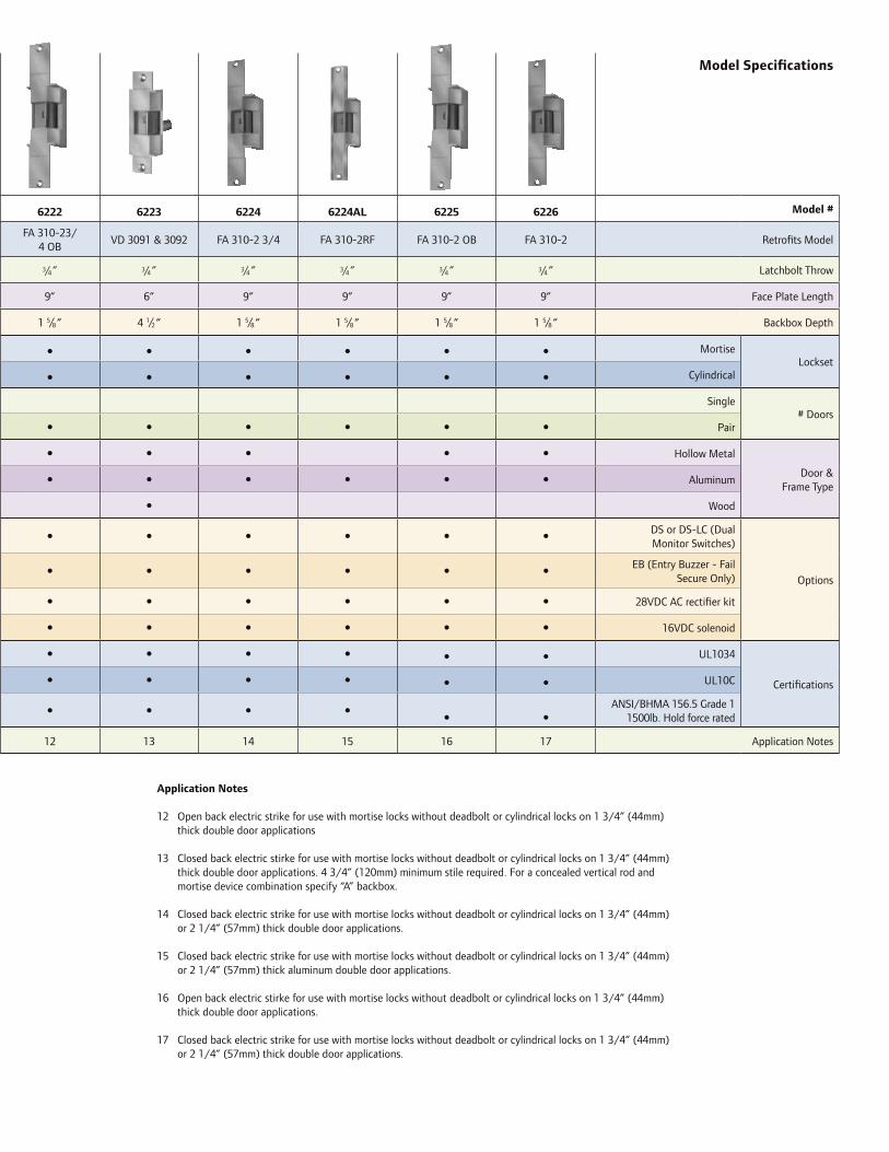
Model Specifications
6222 6223 6224 6224AL 6225 6226 Model #
FA 310-23/ 4 OB
VD 3091 & 3092 FA 310-2 3/4 FA 310-2RF FA 310-2 OB FA 310-2 Retrofits Model
3/4 ” 3/4 ” 3/4 ” 3/4 ” 3/4 ” 3/4 ” Latchbolt Throw
9” 6” 9” 9” 9” 9” Face Plate Length
1 5/8 ” 4 1/2 ” 1 5/8 ” 1 5/8 ” 1 5/8 ” 1 5/8 ” Backbox Depth
MortiseLockset
Cylindrical
Single# Doors
Pair
Hollow Metal
Door & Frame Type
Aluminum
Wood
DS or DS-LC (Dual Monitor Switches)
Options
EB (Entry Buzzer - Fail Secure Only)
28VDC AC rectifier kit
16VDC solenoid
UL1034
Certifications UL10C
ANSI/BHMA 156.5 Grade 1 1500lb. Hold force rated
12 13 14 15 16 17 Application Notes
Model Specifications
Model # 6212WF 6213 6214 6215 6216 6221
Retrofits Model n/aVD 3041, 3042,
3061, 3062FA 310-2 3/4 FA 310-2 FA 310-3-1 VD 3071 & 3072
Latchbolt Throw 3/4 ” 3/4 ” 3/4 ” 3/4 ” 3/4 ” 3/4 ”
Face Plate Length 6 3/8 ” 6” 9” 9” 9” 6”
Backbox Depth 4 3/4 ” 2 1/2 ” 1 5/8 ” 1 5/8 ” 3 5/32” 4 3/4 ”
Lockset
Mortise
Cylindrical
# DoorsSingle
Pair
Door & Frame Type
Hollow Metal
Aluminum †
Wood See note 7 below
Options
DS or DS-LC (Dual Monitor Switches)
EB (Entry Buzzer - Fail Secure Only)
28VDC AC rectifier kit
16VDC solenoid
Certifications
UL1034
UL10C
ANSI/BHMA 156.5 Grade 1 1500lb. Hold force rated
Application Notes 6 7 8 9 10 11
Application Notes
12 Open back electric strike for use with mortise locks without deadbolt or cylindrical locks on 1 3/4” (44mm) thick double door applications
13 Closed back electric stirke for use with mortise locks without deadbolt or cylindrical locks on 1 3/4” (44mm) thick double door applications. 4 3/4” (120mm) minimum stile required. For a concealed vertical rod and mortise device combination specify “A” backbox.
14 Closed back electric strike for use with mortise locks without deadbolt or cylindrical locks on 1 3/4” (44mm) or 2 1/4” (57mm) thick double door applications.
15 Closed back electric strike for use with mortise locks without deadbolt or cylindrical locks on 1 3/4” (44mm) or 2 1/4” (57mm) thick aluminum double door applications.
16 Open back electric stirke for use with mortise locks without deadbolt or cylindrical locks on 1 3/4” (44mm) thick double door applications.
17 Closed back electric strike for use with mortise locks without deadbolt or cylindrical locks on 1 3/4” (44mm) or 2 1/4” (57mm) thick double door applications.

Dimensions
6211AL
6211
6210
6211WF
6212
6214
6213
6212WF
6215
6216
1 15/32"(37mm)
1 11/16"(43mm)
3 3/8"(86mm)
2 1/16"(52mm)
1/8"(3mm)
12" (305mm)Minimum Clearance
6 3/8"(162mm)
7/8"(22mm)
1/2"(13mm)
1/2"(13mm)
1 1/4"(32mm)
1 1/4"(32mm)
6 3/8"(162mm)
7/8"(22mm)
1/2"(13mm)
3 3/8"(86mm)
2 1/16"(52mm)
1/8"(3mm)
Minimum Clearance
3 9/16"(90mm)
4 1/2"(114mm)
1 15/32"(37mm)
1 1/4"(32mm)
4 7/8"(124mm)
7/8"(22mm)
1/2"(13mm)
1 3/8"(35mm)
1 3/4"(44mm)
3 3/8"(86mm)
3 1/4"(83mm)
1/8"(3mm)
12"(305mm)
1 9/16"(38mm)
1 1/4"(32mm)
4 7/8"(124mm)
1 1/4"(32mm) 1/2"
(13mm)
7/8"(22mm)
Minimum Clearance
1 11/16"(43mm)
3 3/8"(86mm)
2 1/16"(52mm)
1/8"(3mm)
1 15/32"(37mm)
12"(305mm)
1 1/4"(32mm)
4 7/8"(124mm)
7/8"(22mm)
1 1/4"(32mm) 1/2"
(13mm)
Minimum Clearance
12"(305mm)
1 15/32"(37mm)
1 11/16"(43mm)
3 3/8"(86mm)
2 1/6"(52mm)
1/8"(3mm)
4 7/8"(124mm)
1 1/4"(32mm)
7/8"(22mm)
3 3/8"(86mm)
2 1/6"(52mm)
1/8"(3mm)
Minimum Clearance
3 9/16"(90mm)
4 1/2"(114mm)
1 15/32"(37mm)
6"(152mm)
2 3/16"(56mm)
1 "(25mm)
1 1/4"(32mm)
1 1/4"(32mm)
1 3/8"(35mm)
1/4"(6mm)
4 1/2"(114mm)
21/29"(64mm)
3 7/8"(98mm)
MinimumClearance
9"(229mm)
1"(25mm)
11/16"(17mm)
1 3/8"(35mm)
2"(51mm)
1 5/8"(41mm)
3 3/4"(95mm)
1 5/8"(41mm)
5/32"(4mm)
12"(305mm)Minimum Clearance
9"(229mm)1"
(25mm)
11/16"(17mm)
1 3/8"(35mm)
1 5/8"(41mm)
1 1/2"(38mm)
1 5/8"(41mm)
3 3/4"(95mm)
5/32"(4mm)
12 "(305mm)Minimum Clearance
9"(229mm)
1"(25mm)
3/4"(19mm)
1 3/8"(35mm)
1 5/8"(41mm)
5 3/8"(137mm) 3 3/4"
(95mm)
5/32"(4mm)
1 5/8"(41mm)
Minimum Clearance
6 1/8"(156mm)
2 7/8"(73mm)
35/32"(80mm)
(38mm)
(41mm)
(95mm)
(4mm)
(305mm)
9"(229mm)
1"(25mm)
3/4"(19mm)
1 3/8"(35mm)
1 5/8"(41mm)
5 3/8"(137mm) 3 3/4"
(95mm)
5/32"(4mm)
15/16"(24mm)
Minimum Clearance
6 1/8"(156mm)
2 7/8"(73mm)
3 5/32"(80mm)

Dimensions
6223
6222
6221
6224
6224AL
6226
6225
6 "(152mm)
3 7/8"(98mm)
1 3/4"(44mm)
1 1/4"(32mm)
MinimumClearance1 7/16"
(37mm)
4 1/2"(114mm)
1 1/4"(32mm)
3 7/8"(98mm)
6"(152mm)
1"(25mm)
1 3/4"(44mm)
3 7/8"(98mm)
MinimumClearance
3 7/8"(98mm)
1 3/8"(35mm)
1 1/4"(32mm) 4 1/2"
(114mm)
1/4"(6mm)
9"(229mm)
1 3/8"(35mm)
1"(25mm)
11/16"(17mm)
5/32"(4mm)
1 5/8"(41mm)
3 3/4"(95mm)
1 5/8"(41mm)
2"(51mm)
12"(305mm)Minimum Clearance
1 3/8"(35mm)
1 5/8"(41mm)
9"(229mm)
1"(25mm)
11/16"(17mm)
1 1/2"(38mm)
1 5/8"(41mm)
3 3/4"(95mm)
1 5/8"(41mm)
5/32"(4mm)
12"(305mm)Minimum Clearance
1 5/8"(41mm)
1 3/8"(35mm)
9"(229mm)
2 1/16"(22mm)
12"(305mm)MinimumClearance
5/32"(4mm)
3 3/4"(95mm)
1 1/2"(38mm)
1 5/8"(41mm)
9"(229mm)
1 3/8"(35mm)
1 5/8"(41mm)
1"(25mm)
11/16"(17mm)
12"(305mm)Minimum Clearance
1 1/2"(38mm)
1 5/8"(41mm)
3 3/4"(95mm)
5/32"(4mm)
9"(229mm)
1 5/8"(41mm)
1 3/8"(35mm)
2 1/16"(41mm) 2"(51mm)
1 5/8"(41mm)
3 3/4"(95mm)
12"(305mm)MinimumClearance
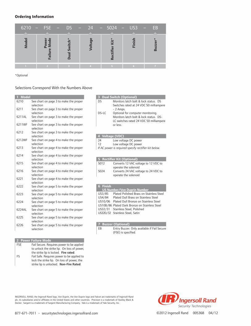
877-671-7011 • securitytechnologies.ingersollrand.com ©2012 Ingersoll Rand 005368 04/12
INGERSOLL RAND, the Ingersoll Rand logo, Von Duprin, the Von Duprin logo and Falcon are trademarks of Ingersoll-Rand plc, its subsidiaries and/or affiliates in the United States and other countries. Precision is a trademark of Stanley Black & Decker. Sargent is a trademark of Sargent Manufacturing Company. Yale is a trademark of Yale Security, Inc.
Ordering Information
Mod
el
Pow
er
Failu
re M
ode
Dua
l Sw
itch
*
Vol
tage
Rec
tifi
er K
it*
Fini
sh
Buz
zer*
1 2 3 4 5 6 7
*Optional
Selections Correspond With the Numbers Above
2 Power Failure ModeFSE Fail Secure. Requires power to be applied
to unlock the strike lip. On loss of power, the strike lip is locked. Fire rated.
FS Fail Safe. Requires power to be applied to lock the strike lip. On loss of power, the strike lip is unlocked. Non-Fire Rated.
4 Voltage (VDC)24 Low voltage DC power12 Low voltage DC powerIf AC power is required specify rectifier kit below.
1 Model6210 See chart on page 3 to make the proper
selection6211 See chart on page 3 to make the proper
selection6211AL See chart on page 3 to make the proper
selection6211WF See chart on page 3 to make the proper
selection6212 See chart on page 3 to make the proper
selection6212WF See chart on page 4 to make the proper
selection6213 See chart on page 4 to make the proper
selection6214 See chart on page 4 to make the proper
selection6215 See chart on page 4 to make the proper
selection6216 See chart on page 4 to make the proper
selection6221 See chart on page 4 to make the proper
selection6222 See chart on page 5 to make the proper
selection6223 See chart on page 5 to make the proper
selection6224 See chart on page 5 to make the proper
selection6224AL See chart on page 5 to make the proper
selection6225 See chart on page 5 to make the proper
selection6226 See chart on page 5 to make the proper
selection
3 Dual Switch (Optional)DS Monitors latch bolt & lock status. DS
Switches rated at 24 VDC 50 milliampere - 2 Amps.
DS-LC Optional for computer monitoring. Monitors latch bolt & lock status. DS-LC switches rated 24 VDC 50 milliampere or less.
5 Rectifier Kit (Optional)S012 Converts 12 VAC voltage to 12 VDC to
operate the solenoidS024 Converts 24 VAC voltage to 24 VDC to
operate the solenoid
6 Finish US Number/Von Duprin NumberUS3/85 Plated Polished Brass on Stainless SteelUS4/84 Plated Dull Brass on Stainless SteelUS10/06 Plated Dull Bronze on Stainless SteelUS10B/86 Plated Dark Bronze on Stainless SteelUS32/31 Stainless Steel, PolishedUS32D/32 Stainless Steel, Satin
7 Buzzer (Optional)EB Entry Buzzer. Only available if Fail Secure
(FSE) is specified.
6210 – FSE – DS – 24 – S024 – US3 – EB
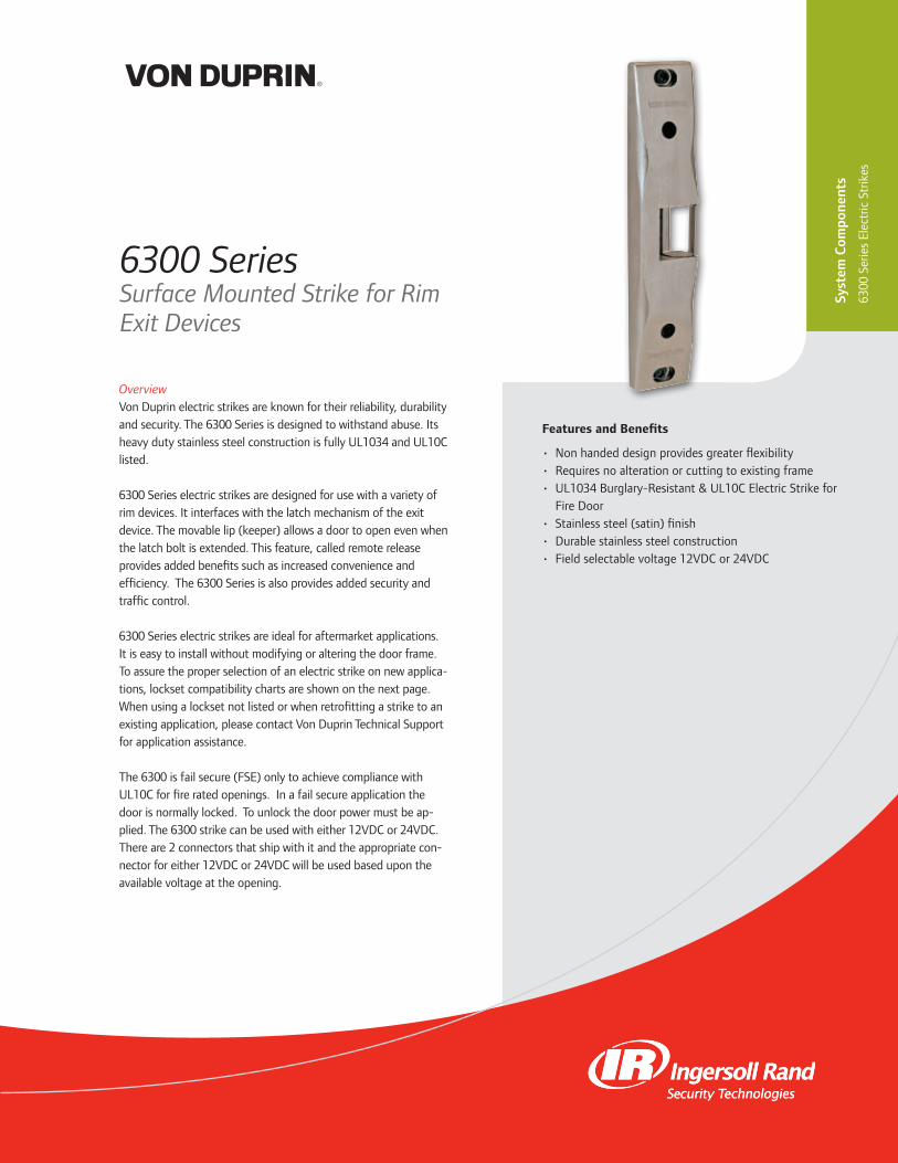
OverviewVon Duprin electric strikes are known for their reliability, durability and security. The 6300 Series is designed to withstand abuse. Its heavy duty stainless steel construction is fully UL1034 and UL10C listed.
6300 Series electric strikes are designed for use with a variety of rim devices. It interfaces with the latch mechanism of the exit device. The movable lip (keeper) allows a door to open even when the latch bolt is extended. This feature, called remote release provides added benefits such as increased convenience and efficiency. The 6300 Series is also provides added security and traffic control.
6300 Series electric strikes are ideal for aftermarket applications. It is easy to install without modifying or altering the door frame. To assure the proper selection of an electric strike on new applica-tions, lockset compatibility charts are shown on the next page. When using a lockset not listed or when retrofitting a strike to an existing application, please contact Von Duprin Technical Support for application assistance.
The 6300 is fail secure (FSE) only to achieve compliance with UL10C for fire rated openings. In a fail secure application the door is normally locked. To unlock the door power must be ap-plied. The 6300 strike can be used with either 12VDC or 24VDC. There are 2 connectors that ship with it and the appropriate con-nector for either 12VDC or 24VDC will be used based upon the available voltage at the opening.
Features and Benefits
• Non handed design provides greater flexibility • Requires no alteration or cutting to existing frame • UL1034 Burglary-Resistant & UL10C Electric Strike for Fire Door
• Stainless steel (satin) finish • Durable stainless steel construction • Field selectable voltage 12VDC or 24VDC
Syst
em C
ompo
nent
s
6300
Ser
ies
Elec
tric
Str
ikes
6300 SeriesSurface Mounted Strike for Rim Exit Devices

877-671-7011 • securitytechnologies.ingersollrand.com
6300 Surface Mount Specifications
Model Voltage Current Duty Amps Ohms
6300 12V DC Continuous 0.50 22
6300 24V DC Continuous 0.24 89
DC = Direct CurrentContinuous Duty = Energized 1 min. or more
Rim Exit Device Compatibility 6300 Strikes
Manufacturer Model Number
Von Duprin VD 22/22-F Rim
Von Duprin VD 33A/35A Rim
Von Duprin VD 55 Rim
Von Duprin VD 88/88-F Rim device
Von Duprin VD 98/99 and 98/99-F Rim
Falcon Falcon 24/24-F Rim
Falcon Falcon 25/25-F Rim
Falcon Falcon 19/19-F Rim
Falcon Doromatic Falcon Doromatic 1790
Falcon Doromatic Falcon Doromatic 2090
* Note: When using device not listed or when retrofitting a strike to an existing application, please contact Von Duprin Technical Support for application assistance.
Wiring
Model Specifications
Model # 6300
Retrofits Model N/A
Latchbolt Throw 3/4 ”
Face Plate Length 9”
Projection 3/4 ”
Lockset Rim Exit Device
# Doors Single or Pair with Mullion
Door/Frame Type Hollow Metal, Aluminum & Wood
EB (Entry Buzzer) Optional
Certifications UL1034, UL10C
Application Notes Surface mounted electric strike ideal for aftermarket applications. Strike designed for use with Von Duprin 98/99, however it can be used with most rim exit devices.
AC
3/4"(19.0mm)
1-5/8"(42.0mm)
9"(228.6mm)
8-1/4"(209.6mm)
1-3/4"(44.5mm)
5-1/2"(139.7mm)
HORIZONTALADJUSTMENTMOUNTING HOLES
LOCK DOWNHOLES
©2012 Ingersoll Rand 003242 04/12
INGERSOLL RAND, the Ingersoll Rand logo, Von Duprin, the Von Duprin logo, Falcon, and Falcon Doromatic are trademarks of Ingersoll-Rand plc, its subsidiaries and/or affiliates in the United States and other countries.
Selections Correspond With the Numbers Above* Optional
1 Model6300 Surface Mounted Strike for Rim Exit Devices
2 Rectifier Kit (Optional)S012 Converts 12 VAC voltage to 12 VDC to operate the solenoidS024 Converts 24 VAC voltage to 24 VDC to operate the solenoid
3 Buzzer (Optional)EB Entry Buzzer.
Ordering Information6300 S024 EB
Mod
el
Rec
tifi
er
Kit
*
Buz
zer*
1 2 3
AC with Buzzer
DC
DC with Buzzer
Standard Features:• Power Failure Mode: Fail Secure (FSE)• Voltage: Field selectable 24 VDC or 12 VDC• Finish: Stainless Steel, Satin (US32D/32)

OverviewThe ES-6400 fire rated strike from Schlage combines strength and convenience in an “all in one” compact, easy to install design. The ES-6400 is UL listed for 1500 lb. static strength.
The unique design of the ES-6400 allows the installer to move the deadbolt keeper or plug and deadlatch ramp vertically to align with a wide variety of mortise locks with offset latches. This combined with a 1/8” horizontal adjustment provides a highly flexible and easy to install design while also eliminating the need for special face plates.
A trim plate for frame cuts and a hands-free adhesive paper template are provided to simplify installation. Additional flexibility is provided by a “plug in” latch monitor switch that can be added in the field at any time after installation.
The power failure mode of the ES-6400 is fail secure only for fire rated openings. In a fail secure application the door is normally locked without power. To unlock the door power must be applied. The voltage of the ES-6400 is also field selectable 12 or 24 VDC and 12 to 24 VAC.
Features and Benefits
• Vertical adjustment of the deadbolt keeper or deadlatch ramp allows for alignment with a wide variety of mortise locks with offset latches
• Field selectable voltage 12 or 24VDC and 12 to 24VAC • Accommodates 3/4” latch projection • Centerline face plate included for centerline entry • Accommodates up to 1” deadbolt (for night latch application only, bolt will not release)
• Horizontal adjustment of up to 1/8” for misaligned frames
• Heavy duty stainless steel construction • Plug connectors are furnished for ease of installation and removal during strike servicing
• Optional plug-in latch monitor can be added in the field • Non-handed design provides greater flexibility • Tamper-resistant screws included • Hex and security driver bit included • Low current draw (0.19 amps @ 24 VDC) • Unique solenoid design prevents keeper from heating up • Trim plate included • Adhesive paper template included • UL listed for 1500 lb. static strength, UL 1034 burglary-resistant listed & UL 10 C 3 hour fire-rated (fail secure only)
Syst
em C
ompo
nent
s
ES-6
400-
Serie
s M
odul
ar S
trik
e
ES-6400 SeriesModular Strike
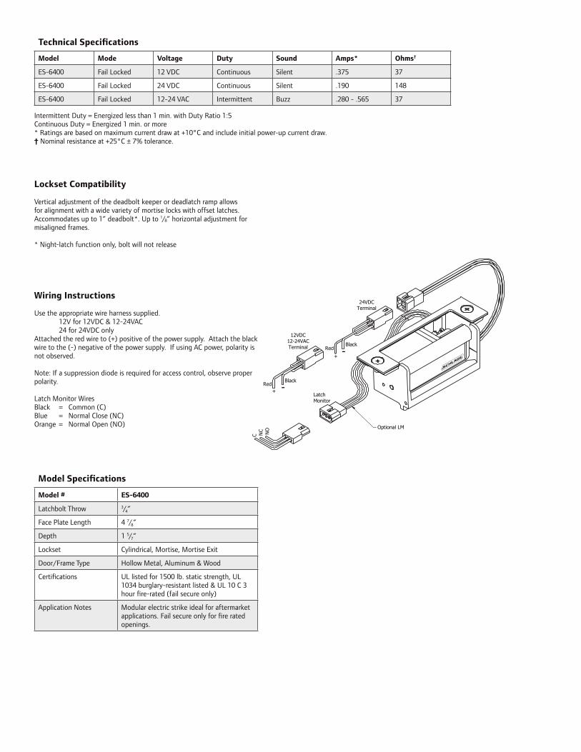
RedBlack
+ -
+-Red
Black
24VDCTerminal
12VDC12-24VACTerminal
NO
NC
C
LatchMonitor
Optional LM
Technical Specifications
Model Mode Voltage Duty Sound Amps* Ohms†
ES-6400 Fail Locked 12 VDC Continuous Silent .375 37
ES-6400 Fail Locked 24 VDC Continuous Silent .190 148
ES-6400 Fail Locked 12-24 VAC Intermittent Buzz .280 - .565 37
Intermittent Duty = Energized less than 1 min. with Duty Ratio 1:5Continuous Duty = Energized 1 min. or more* Ratings are based on maximum current draw at +10°C and include initial power-up current draw.† Nominal resistance at +25°C ± 7% tolerance.
Model Specifications
Model # ES-6400
Latchbolt Throw 3/4”
Face Plate Length 4 7/8”
Depth 1 5/7”
Lockset Cylindrical, Mortise, Mortise Exit
Door/Frame Type Hollow Metal, Aluminum & Wood
Certifications UL listed for 1500 lb. static strength, UL 1034 burglary-resistant listed & UL 10 C 3 hour fire-rated (fail secure only)
Application Notes Modular electric strike ideal for aftermarket applications. Fail secure only for fire rated openings.
Lockset Compatibility
Vertical adjustment of the deadbolt keeper or deadlatch ramp allows for alignment with a wide variety of mortise locks with offset latches. Accommodates up to 1” deadbolt*. Up to 1/8” horizontal adjustment for misaligned frames.
* Night-latch function only, bolt will not release
Wiring Instructions
Use the appropriate wire harness supplied. 12V for 12VDC & 12-24VAC 24 for 24VDC onlyAttached the red wire to (+) positive of the power supply. Attach the black wire to the (-) negative of the power supply. If using AC power, polarity is not observed.
Note: If a suppression diode is required for access control, observe proper polarity.
Latch Monitor WiresBlack = Common (C)Blue = Normal Close (NC)Orange = Normal Open (NO)

877-671-7011 • securitytechnologies.ingersollrand.com ©2012 Ingersoll-Rand Company 009011 08/12
INGERSOLL RAND, the Ingersoll Rand logo, Schlage, and the Schlage logo are trademarks of Ingersoll-Rand plc, its subsidiaries and/or affiliates in the United States and other countries.
Dimensions
1-1/4” (31.8 mm)
3/4” (19.6 mm)3/8” (9.0 mm)
4-1/8” (105.0 mm)
4-7/8” (123.0 mm)
3-3/8” (85.1 mm)
3-1/8” (79.8 mm)
5/8” (15.9 mm)1-5/8” (42.0 mm) FACEPLATE FOR
OFFSET LOCKS
1-5/8” (41.0 mm)
1-3/4” (46.0 mm)
1/4” (5.8 mm)
1-3/8” (36.5 mm)
4-5/8” (116.0 mm)
3-1/4” (83.7 mm)
1-1/4” (31.8 mm) 3/8” (9.0 mm)
1-1/2” (38.0 mm)
4-1/8” (105.0 mm)
4-7/8” (123.0 mm)
FACEPLATE FOR CENTERLINE LOCKS(included)5/8” (15.9 mm)
Certifications/Listings
UL1034 Listed - Burglary Resistant
UL10C Certified - 3 Hour FIre Rated
NOTE: Not to scale. Specifications are subject to change without notice.
ORDERING INFORMATION
ES-6400 - Modular Strike
OPTIONS
LM – Indicates when door is latched (ships separately)
STANDARD FEATURES
• Power Failure Mode: Fail secure only for fire rated openings• Voltage: 12 or 24 VDC and 12 to 24 VAC voltage is field selectable• Finish: Stainless Steel, Satin (US32D)

THIS PAGE IS INTENTIONALLY BLANK.

OverviewThe Von Duprin 5100 Electric Strike has been designed and manufactured to meet the needs of locksmiths and security professionals. This easy-to-install electric strike was created for medium duty applications, specifically to control traffic flow through interior and exterior openings in retail and commercial environments.
Features and Benefits
• Three faceplates standard in every box • 12/24 dual-voltage • Fail-safe/fail-secure • Adjustable keeper • Internal solenoid • Non-handed • Backbox depth of 1 11/16” • Keeper depth of 1/2” • Mounting tabs • Retrofit kit • Illustrated installation instructions • Tamper resistant • 1 year electrical product warranty • Continuous duty operation • Heavy duty construction
5100 SeriesElectric Strikes
Syst
em C
ompo
nent
s
5100
Ser
ies
Elec
tric
Str
ikes

877-671-7011 • vonduprin.com ©2011 Ingersoll Rand ES-5990 07/11
Specifications
ANSI/BHMA 156.5 Grade 1
UL 1034 Burglary Listing
12VDC 24VDC
Resistance (Ohms) 32 128
Power (watts) 4.5 4.5
Current (amps) 0.38 0.19
All specs ± 10% @77°F/25°C
POWER OPTIONS
• DC: Regulated Power Supplies (Recommended) - PS902 Power Supply
• DC: 24V Unregulated Power Supplies (Acceptable) - Schlage 593 PI-24DC (Plug-In) - Schlage 592-24RC (Hard-Wired)
• AC/DC Conversion: - Von Duprin SO-24 Kit
STANDARD CONFIGURATION
• 24 volts DC • Fail-secure
• Field convertible to Fail-safe
DIMENSIONS
• Backbox: 3 3/8” x 1” x 1 11/32” • Overall Strike Depth: 1 11/16”
• Faceplates: - 4 7/8” round corner ANSI A115.2 standard frame prep - 4 7/8” square corner ANSI A115.2 standard frame prep
- 7 15/16” long, round corner wood frame prep• Keeper pocket: 1 7/16”L x 1/2”D x 11/16” - 13/16”W (adjustable)
• Lip Attachment cut-out depth: 1 1/16”
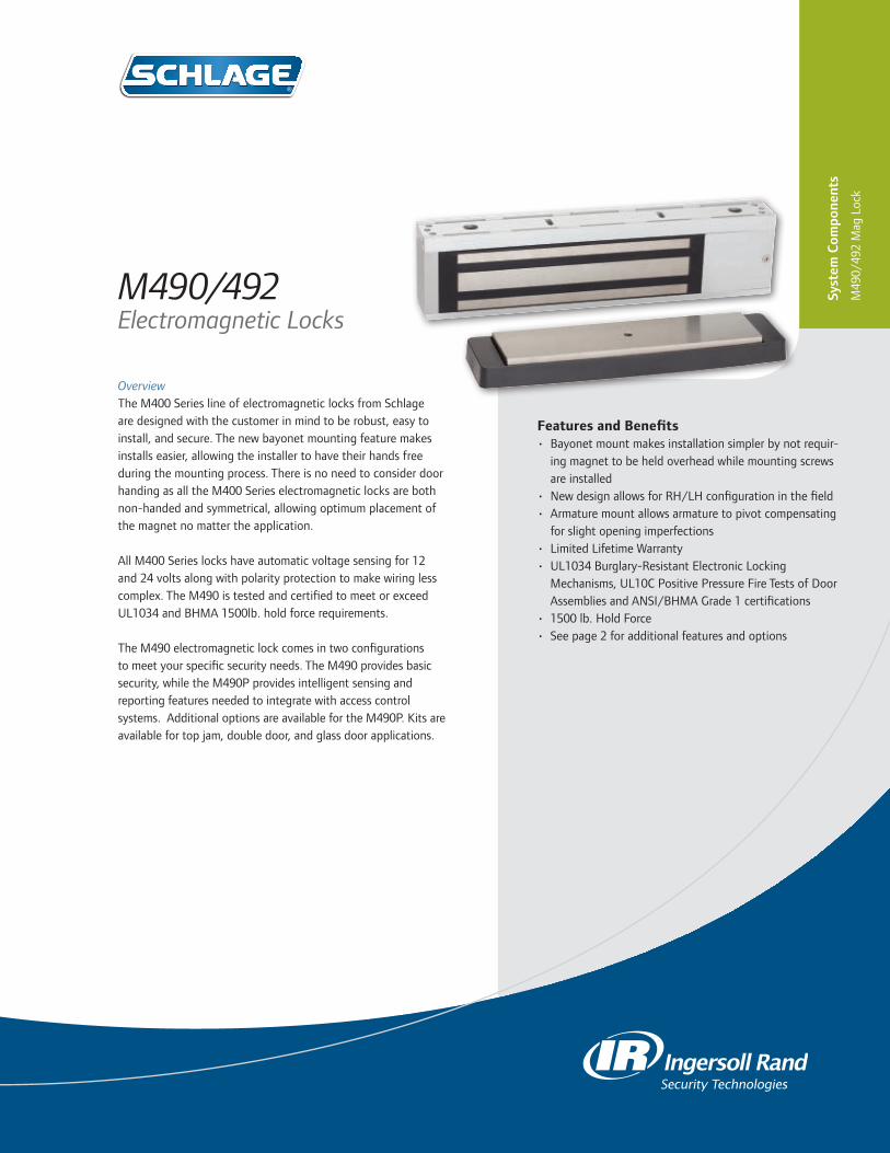
Features and Benefits • Bayonet mount makes installation simpler by not requir-
ing magnet to be held overhead while mounting screws are installed
• New design allows for RH/LH configuration in the field• Armature mount allows armature to pivot compensating
for slight opening imperfections• Limited Lifetime Warranty• UL1034 Burglary-Resistant Electronic Locking
Mechanisms, UL10C Positive Pressure Fire Tests of Door Assemblies and ANSI/BHMA Grade 1 certifications
• 1500 lb. Hold Force• See page 2 for additional features and options
OverviewThe M400 Series line of electromagnetic locks from Schlage are designed with the customer in mind to be robust, easy to install, and secure. The new bayonet mounting feature makes installs easier, allowing the installer to have their hands free during the mounting process. There is no need to consider door handing as all the M400 Series electromagnetic locks are both non-handed and symmetrical, allowing optimum placement of the magnet no matter the application.
All M400 Series locks have automatic voltage sensing for 12 and 24 volts along with polarity protection to make wiring less complex. The M490 is tested and certified to meet or exceed UL1034 and BHMA 1500lb. hold force requirements.
The M490 electromagnetic lock comes in two configurations to meet your specific security needs. The M490 provides basic security, while the M490P provides intelligent sensing and reporting features needed to integrate with access control systems. Additional options are available for the M490P. Kits are available for top jam, double door, and glass door applications.
M490/492Electromagnetic Locks
Syst
em C
ompo
nent
s
M49
0/49
2 M
ag L
ock

877-671-7011 • schlage.com ©2013 Ingersoll Rand 004204 01/13
M490/M492 Electromagnetic Lock Specifications
Specification M490/M490P M492/M492P
Holding Force meets or exceeds BHMA standard of 1500 lbs.
meets or exceeds BHMA standard of 1500 lbs.
Input Voltage (Standard Unit) 12/24 VDC
Current Draw (Amps Standard Unit)
.65A @ 12 VDC
.35A @ 24 VDC1.3A @ 12 VDC.7A @ 24 VDC
Automatic Dual Voltage 12/24 VDC
Height 3" 3"
Length 12 - 1/2" 25 - 1/16"
Width 1 - 3/4" 1 - 3/4"
Weight (approximate) 14 lbs. 28 lbs.
Certifications UL10C, UL1034, ANSI/BHMA A156.23
Temperature 0º-49º C (32º-120º F)
Wire Gauge 14-22 AWG
Filler Plates and Angle Brackets Specifications
M490 M492
Length 10-1/2" 20- 5/8"
Filler Plates
Width x Height
1-1/4" x 1/8" 4901F 4921F
1-1/4" x 1/4" 4902F 4922F
1-1/4" x 3/8" 4903F 4923F
1-1/4" x 1/2" 4904F 4924F
1-1/4" x 5/8" 4905F 4925F
3/4" x 1/2" 4906F 4926F
3/4" x 5/8" 4907F 4927F
3/4" x 3/4" 4908F 4928F
Angle Brackets
Width x Height Plate No. Plate No.
1"x1" 4901A 4921A
1-1/2" x 1" 4902A 4922A
1-1/2" x 1-1/2" 4903A 4923A
1-1/2" x 2" 4904A 4924A
1-1/2" x 2 -1/2" 4905A 4925A
ADDITIONAL FEATURES
M490/M492• Automatic Voltage Selection (AVS) senses the
voltage applied to the lock and responds accordingly
M490P/M492P• Magnetic Bond Sensor (MBS) monitors the
strength of the bond between the lock and armature so you know the door is secure
• Door Position Switch (DPS) monitors whether the door is open or closed
• Relock Time Delay (RTD) provides a relock delay that is adjustable from 0.5 to 30 seconds
Optional
- Anti-Tamper Switch (ATS) provides an indication that the cover of the magnet is securely fastened to the lock and that the on board circuitry is secure
- MBS Indicator (LED) provides visual indication of magnetic bond at the lock
OPTIONS (FOR ALL)
• Herculite Door Bracket
• Top Jamb (inswinging doors)

Features and Benefits
• Bayonet mount makes installation simpler by not requiring magnet to be held overhead while mounting screws are installed
• New design allows for RH/LH configuration in the field• Armature mount allows armature to pivot compensating
for slight opening imperfections• Limited Lifetime Warranty• UL1034 Burglary-Resistant Electronic Locking
Mechanisms, UL10C Positive Pressure Fire Tests of Door• 1000 lb. Hold Force• See page 2 for additional features and options
OverviewThe M400 Series line of electromagnetic locks from Schlage are designed with the customer in mind to be robust, easy to install, and secure. The new bayonet mounting feature makes installs easier, allowing the installer to have their hands free during the mounting process. There is no need to consider door handing as all the M400 Series electromagnetic locks are both non-handed and symmetrical, allowing optimum placement of the magnet no matter the application.
All M400 Series locks have automatic voltage sensing for 12 and 24 volts along with polarity protection to make wiring less complex. The M450 is tested and certified to meet or exceed UL1034 and BHMA 1000lb. hold force requirements.
The M450 electromagnetic lock comes in two configurations to meet your specific security needs. The M450 provides basic security, while the M450P provides intelligent sensing and reporting features needed to integrate with access control sys-tems. Additional options are available for the M450P. Kits are available for top jam, double door, and glass door applications.
M450/452Electromagnetic Locks
Syst
em C
ompo
nent
s
M45
0/45
2 M
ag L
ock

877-671-7011 • securitytechnologies.ingersollrand.com ©2012 Ingersoll Rand 004205 11/12
M450/M452 Electromagnetic Lock Specifications
Specification M450/M450P M452/M452P
Holding Force meets or exceeds BHMA standard of 1000 lbs.
1000 lbs. per door leaf
Input Voltage (Standard Unit) 12/24 VDC
Current Draw (Amps Standard Unit)
.75A @ 12 VDC
.38A @ 24 VDC1.5A @ 12 VDC.75A @ 24 VDC
Automatic Dual Voltage 12/24 VDC
Height 3" 3"
Length 10 - 1/4" 20 - 9/16"
Width 1 - 3/4" 1 - 3/4"
Weight (approximate) 10 lbs. 20 lbs.
Certifications UL1034, UL10C, ANSI/BHMA156.23
Temperature 0º-49º C (32º-120º F)
Wire Gauge 14-22 AWG
ADDITIONAL FEATURES
M450/M452• Automatic Voltage Selection (AVS) senses the
voltage applied to the lock and responds accordingly
M450P/M452P• Magnetic Bond Sensor (MBS) monitors the
strength of the bond between the lock and armature so you know the door is secure
• Door Position Switch (DPS) monitors whether the door is open or closed
• Relock Time Delay (RTD) provides a relock delay that is adjustable from 0.5 to 30 seconds
Optional (P models only)
- Anti-Tamper Switch (ATS) provides an indication that the cover of the magnet is securely fastened to the lock and that the on board circuitry is secure
- MBS Indicator (LED) provides visual indication of magnetic bond at the lock
OPTIONS (FOR ALL)
• Herculite Door Bracket• Top Jamb (inswinging doors)
Filler Plates and Angle Brackets Specifi-
cations
M450
Length 10-1/2"
Filler Plates (Order 2 if purchasing a double lock)
Width x Height
1-1/4" x 1/8" 4501F
1-1/4" x 1/4" 4502F
1-1/4" x 3/8" 4503F
1-1/4" x 1/2" 4504F
1-1/4" x 5/8" 4505F
3/4" x 1/2" 4506F
3/4" x 5/8" 4507F
3/4" x 3/4" 4508F
Angle Brackets (Order 2 if purchasing a double lock)
Width x Height Plate No.
1"x1" 4501A
1-1/2" x 1" 4502A
1-1/2" x 1-1/2" 4503A
1-1/2" x 2" 4504A
1-1/2" x 2 -1/2" 4505A

Features and Benefits
• Bayonet mount makes installation simpler by not requiring magnet to be held overhead while mounting screws are installed
• New design allows for RH/LH configuration in the field• Armature mount allows armature to pivot compensating
for slight opening imperfections• Limited Lifetime Warranty• UL1034 Burglary-Resistant Electronic Locking
Mechanisms, UL10C Positive Pressure Fire Tests of Door Assemblies and ANSI/BHMA Grade 1 certifications
• 500 lb. Hold Force• See page 2 for additional features and options
OverviewThe M400 Series line of electromagnetic locks from Schlage are designed with the customer in mind to be robust, easy to install, and secure. The new bayonet mounting feature makes installs easier, allowing the installer to have their hands free during the mounting process. There is no need to consider door handing as all the M400 Series electromagnetic locks are both non-handed and symmetrical, allowing optimum placement of the magnet no matter the application.
All M400 Series locks have automatic voltage sensing for 12 and 24 volts along with polarity protection to make wiring less complex. The M420 is tested and certified to meet or exceed UL1034 and BHMA 500lb. hold force requirements.
The M420 electromagnetic lock comes in two configurations to meet your specific security needs. The M420 provides basic security, while the M420P provides intelligent sensing and reporting features needed to integrate with access control systems. Additional options are available for the M420P. Kits are available for top jam, double door, and glass door applications.
M420/422Electromagnetic Locks
Syst
em C
ompo
nent
s
M42
0/42
2 M
ag L
ock
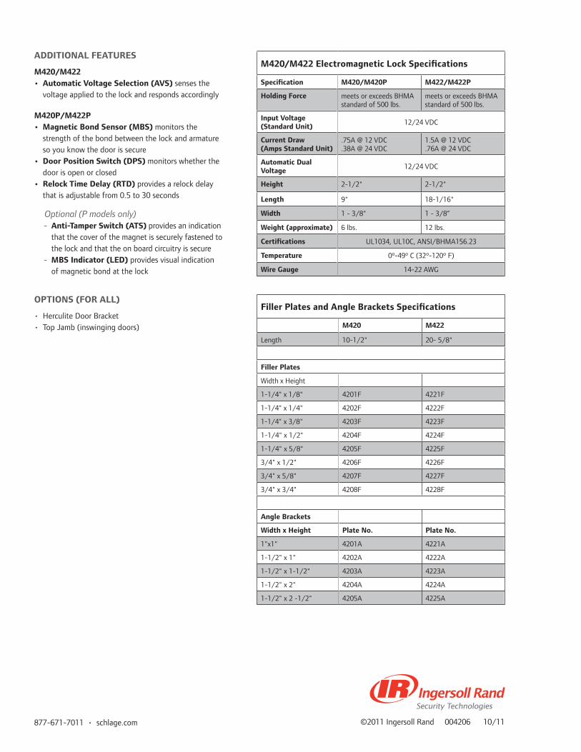
877-671-7011 • schlage.com ©2011 Ingersoll Rand 004206 10/11
M420/M422 Electromagnetic Lock Specifications
Specification M420/M420P M422/M422P
Holding Force meets or exceeds BHMA standard of 500 lbs.
meets or exceeds BHMA standard of 500 lbs.
Input Voltage (Standard Unit) 12/24 VDC
Current Draw (Amps Standard Unit)
.75A @ 12 VDC
.38A @ 24 VDC1.5A @ 12 VDC.76A @ 24 VDC
Automatic Dual Voltage 12/24 VDC
Height 2-1/2" 2-1/2"
Length 9" 18-1/16"
Width 1 - 3/8" 1 - 3/8”
Weight (approximate) 6 lbs. 12 lbs.
Certifications UL1034, UL10C, ANSI/BHMA156.23
Temperature 0º-49º C (32º-120º F)
Wire Gauge 14-22 AWG
ADDITIONAL FEATURES
M420/M422• Automatic Voltage Selection (AVS) senses the
voltage applied to the lock and responds accordingly
M420P/M422P• Magnetic Bond Sensor (MBS) monitors the
strength of the bond between the lock and armature so you know the door is secure
• Door Position Switch (DPS) monitors whether the door is open or closed
• Relock Time Delay (RTD) provides a relock delay that is adjustable from 0.5 to 30 seconds
Optional (P models only)
- Anti-Tamper Switch (ATS) provides an indication that the cover of the magnet is securely fastened to the lock and that the on board circuitry is secure
- MBS Indicator (LED) provides visual indication of magnetic bond at the lock
OPTIONS (FOR ALL)
• Herculite Door Bracket• Top Jamb (inswinging doors)
Filler Plates and Angle Brackets Specifications
M420 M422
Length 10-1/2" 20- 5/8"
Filler Plates
Width x Height
1-1/4" x 1/8" 4201F 4221F
1-1/4" x 1/4" 4202F 4222F
1-1/4" x 3/8" 4203F 4223F
1-1/4" x 1/2" 4204F 4224F
1-1/4" x 5/8" 4205F 4225F
3/4" x 1/2" 4206F 4226F
3/4" x 5/8" 4207F 4227F
3/4" x 3/4" 4208F 4228F
Angle Brackets
Width x Height Plate No. Plate No.
1"x1" 4201A 4221A
1-1/2" x 1" 4202A 4222A
1-1/2" x 1-1/2" 4203A 4223A
1-1/2" x 2" 4204A 4224A
1-1/2" x 2 -1/2" 4205A 4225A

Features and Benefits
• 1500 lbs. of direct holding force• Magnetic Bond Sensor (MBS) and
Gate Status Monitor (DPS)• Field Selectable 12 or 24VDC operation• Built-in voltage spike suppressor• Electroless nickel plated finish• Universal mounting brackets• 1/2˝ EMT compression fitting• Two foot wire leads• Weather resistant for exterior use• Accomodates gate misalignment• No moving parts - low maintenance
OverviewThe Schlage M490G Electromagnetic Gate Lock is a weather resistant electromagnetic lock with 1500 lbs. of holding force, designed for use on all types of sliding and swinging gates. As a high security magnetic lock it can accommodate misalignment problems while supplying superior holding force.
A 1/2˝ compression connector is provided for installation of 1/2˝ EMT conduit, insuring protection of hook-up wiring from weather and vandalism. Heavy duty plating resists corrosion of mating surfaces providing a low maintenance locking device.
A modified Top Jamb mounting bracket allows a single M490G to be mounted in a variety of positions. The M490G Gate Lock may be mounted to any gate frame or post. Special brackets may be required to adapt the lock to a particular frame or post. It is important that the lock is mounted so that the armature pulls straight back from the magnet face.
The M490G can be field configured for either 12 or 24 VDC operation. Magnetic Bond Sensor (MBS) and Gate Status Monitor (DPS) are standard.
M490GElectromagnetic Gate Lock
Syst
em C
ompo
nent
s
M49
0G M
agne
tic G
ate
Lock

877-671-7011 • schlage.com ©2011 Ingersoll Rand ES-6012 07/11
STANDARD FEATURES
M490G• Magnetic Bond Sensor (MBS) monitors the
strength of the bond between the lock and armature so you know the door is secure
• Door Position Switch (DPS) monitors whether the door is open or closed
• Universal Mounting Brackets, for swinging or sliding gate applications
• Built in voltage spike suppression• ½” EMT compression fitting• Special corrosion resistant plating
M490G Electromagnetic Gate Lock Specifications
Specifications M490/M490G
Holding Force Meets or exceeds BHMA standardof 1500 lbs.
Input Voltage (Field Selectable) 12/24 VDC
Current Draw (Amps Standard Unit)
.65A @ 12 VDC
.35A @ 24 VDC
Height 3”
Length 11”
Width 1-3/4”
Weight (approximates) 14 lbs.
Temperature 0°- 49° C (32°- 120° F)
Wire Gauge 14-22 AWG
Filler Plates
Electromagnetic Lock M490G
Length 9”
Width x Height Plate No.
1-1/4” x 1/8” 49G1F
1-1/4” x 1/4” 49G2F
1-1/4” x 3/8” 49G3F
1-1/4” x 1/2” 49G4F
1-1/4” x 5/8” 49G5F
1-1/4” x 3/4” 49G6F
3/4” x 1/2” 49G7F
3/4” x 5/8” 49G8F
Angle Brackets
Electromagnetic Lock M490G
Length 9”
Width x Height Bracket No.
1” x 1” 49G1A
1-1/2” x 1” 49G2A
1-1/2” x 1-1/2” 49G3A
1-1/2” x 2” 49G4A
1-1/2” x 2-1/2” 49G5A
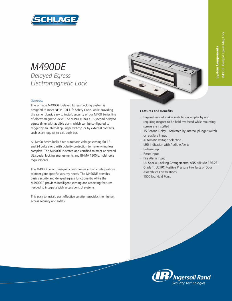
OverviewThe Schlage M490DE Delayed Egress Locking System is designed to meet NFPA 101 Life Safety Code, while providing the same robust, easy to install, security of our M400 Series line of electromagnetic locks. The M490DE has a 15 second delayed egress timer with audible alarm which can be configured to trigger by an internal “plunger switch,” or by external contacts, such as an request to exit push bar.
All M400 Series locks have automatic voltage sensing for 12 and 24 volts along with polarity protection to make wiring less complex. The M490DE is tested and certified to meet or exceed UL special locking arrangements and BHMA 1500lb. hold force requirements.
The M490DE electromagnetic lock comes in two configurations to meet your specific security needs. The M490DE provides basic security and delayed egress functionality, while the M490DEP provides intelligent sensing and reporting features needed to integrate with access control systems.
This easy to install, cost effective solution provides the highest access security and safety.
M490DEDelayed Egress Electromagnetic Lock
Syst
em C
ompo
nent
s
M49
0DE
Del
ayed
Egr
ess
Mag
Loc
k
Features and Benefits
• Bayonet mount makes installation simpler by not requiring magnet to be held overhead while mounting screws are installed
• 15 Second Delay - Activated by internal plunger switch or auxilary imput
• Automatic Voltage Selection• LED Indication with Audible Alerts• Release Input• Reset Input• Fire Alarm Input• UL Special Locking Arrangements, ANSI/BHMA 156.23
Grade 1, UL10C Positive Pressure Fire Tests of Door Assemblies Certifications
• 1500 lbs. Hold Force

877-671-7011 • securitytechnologies.ingersollrand.com ©2013 Ingersoll Rand 004762 01/13
STANDARD FEATURES
M490DE/M490DE-2• Auto Voltage Selection (AVS) senses the voltage
applied to lock and responds accordingly• Internal Plunger Switch activates delayed egress
timer
Additional Options and Accessories• Herculite Door Bracket (HDB)
M490DEP/M490DEP-2• Magnetic Bond Sensor (MBS) monitors the
strength of the bond between the lock and armature so you know the door is secure
• Door Position Switch (DPS) monitors whether the door is open or closed
• Relocking Time Delay• BOCA Compliant (upon request)
Filler Plates
Electromagnetic Lock M490DE/M490DE-2
Length 12-1/2”
Width x Height Plate No.
1-1/4” x 1/8” 4901F
1-1/4” x 1/4” 4902F
1-1/4” x 3/8” 4903F
1-1/4” x 1/2” 4904F
1-1/4” x 5/8” 4905F
3/4” x 1/2” 4906F
3/4” x 5/8” 4907F
3/4” x 3/4” 4908F
Angle Brackets
Electromagnetic Lock M490DE/M490DE-2
Length 10-1/2”
Width x Height Bracket No.
1” x 1” 4901A
1-1/2” x 1” 4902A
1-1/2” x 1-1/2” 4903A
1-1/2” x 2” 4904A
1-1/2” x 2-1/2” 4905A
M490DE Electromagnetic Delayed Egress Lock Specifications
Specification M490DE M490DE-2
Holding Force meets or exceeds BHMA standard of 1500 lbs.
meets or exceeds BHMA standard of 1500 lbs. per door leaf
Input Voltage (Standard Unit) 12/24 VDC
Current Draw (Amps Standard Unit)
.75A @ 12 VDC
.45A @ 24 VDC1.25A @ 12 VDC.76A @ 24 VDC
Height 3" 3"
Length 12 - 1/2" 25 - 1/16"
Width 3 - 1/16" 3 - 1/16"
Weight (approximate) 16 lbs. 32 lbs.
Certifications UL294 Special Locking Arrangement including BOCA, UL1034, UL10C, ANSI/BHMA156.23
Temperature 0º-49º C (32º-120º F)
Wire Gauge 14-22 AWG
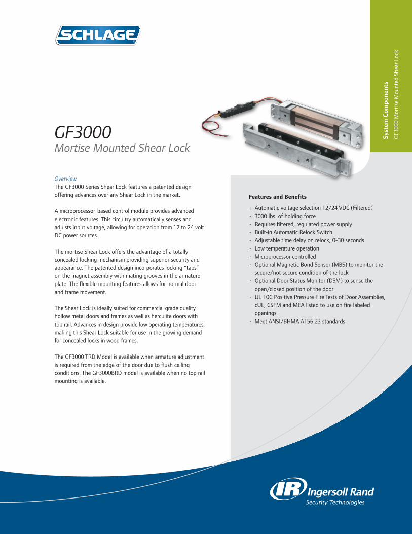
Features and Benefits
• Automatic voltage selection 12/24 VDC (Filtered)• 3000 lbs. of holding force• Requires filtered, regulated power supply• Built-in Automatic Relock Switch• Adjustable time delay on relock, 0-30 seconds• Low temperature operation• Microprocessor controlled• Optional Magnetic Bond Sensor (MBS) to monitor the
secure/not secure condition of the lock• Optional Door Status Monitor (DSM) to sense the
open/closed position of the door• UL 10C Positive Pressure Fire Tests of Door Assemblies,
cUL, CSFM and MEA listed to use on fire labeled openings
• Meet ANSI/BHMA A156.23 standards
OverviewThe GF3000 Series Shear Lock features a patented design offering advances over any Shear Lock in the market.
A microprocessor-based control module provides advanced electronic features. This circuitry automatically senses and adjusts input voltage, allowing for operation from 12 to 24 volt DC power sources.
The mortise Shear Lock offers the advantage of a totally concealed locking mechanism providing superior security and appearance. The patented design incorporates locking “tabs” on the magnet assembly with mating grooves in the armature plate. The flexible mounting features allows for normal door and frame movement.
The Shear Lock is ideally suited for commercial grade quality hollow metal doors and frames as well as herculite doors with top rail. Advances in design provide low operating temperatures, making this Shear Lock suitable for use in the growing demand for concealed locks in wood frames.
The GF3000 TRD Model is available when armature adjustment is required from the edge of the door due to flush ceiling conditions. The GF3000BRD model is available when no top rail mounting is available.
GF3000 Mortise Mounted Shear Lock
Syst
em C
ompo
nent
s
GF3
000
Mor
tise
Mou
nted
She
ar L
ock

877-671-7011 • schlage.com ©2011 Ingersoll Rand 004160 10/11
Specifications
Holding Force 3000 lbs
Current Draw 0.90 Amp @ 12 VDC 0.45 Amp @ 24VDC
Weight 7 lbs
Lock Body: Length x Height x Depth 9-1/2” x 1-1/2” x 1-1/2”
w/Mounting Tabs: Length x Height x Depth 11-9/16” x 1-1/2” x 1-1/2”
Armature: Length x Height x Depth 8-3/8” x 1-3/8” x 1/2”
Armature Bracket: Length x Height x Depth 10-5/8” x 1-3/8” x 1”
Certifications UL 10C Positive Pressure Fire Tests of Door Assemblies
ANSI/BHMA A156.23 1500 lbs
ORDERING INFORMATION
GF3000 Adjustable from top edge of door
GF3000TRD Mounting assembly which provides armature adjustable from the latch edge of the door. Recommended with zero clearance condition between top of door and ceiling.
GF3000BRD Mounting assembly to mortise armature into bottom rail of door. Magnet is installed in floor/threshold. Provides solution when no top rail is available.
OPTIONS
DSM/MBS Door Status Monitor/Magnetic Bond Sensor

Features and Benefits
• Automatic Voltage Selection 12/24 VDC (filtered)• 3000 lbs. of holding force • Requires filtered, regulated power supply• Built-in Automatic Relock Switch• Adjustable time delay on relock, 0-30 seconds• Low temperature operation• Microprocessor controlled• Optional Magnetic Bond Sensor (MBS) to monitor the
secure/not secure condition of the lock• Optional Door Status Monitor (DSM) to sense the
open/closed position of the door• Modular, slide-in in finish plates on SM and TJ models• UL10C Positive Pressure Fire Test of Door Assemblies,
cUL, CSFM and MEA listed to use on fire labeled openings
• Meets ANSI/BHMA 156.23 standards
OverviewThe GF3000 Series Shear Lock features a patented design offering advances over any Shear Lock on the market.
A microprocessor-based control module provides advanced electronic features. This circuitry automatically senses and adjusts input voltage, allowing for operation from 12 to 24 volt DC power sources.
The surface Shear Lock offers the advantage of a totally concealed locking mechanism, providing superior security and appearance. The patented design incorporates locking “tabs” on the magnet assembly with mating grooves in the armature plate. While the strength afforded by this design is a major advantage, the flexible mounting features are as important. This design allows for normal door and frame movement.
This Surface Shear Lock offers maximum versatility in application. The GF3000SM model provides a low profile, surface mount lock for outswinging doors. The GF3000TJ model provides a low profile, surface mount lock for inswinging doors. It provides a unique mounting solution with no brackets needed, which are standard with direct pull magnets.
The GF3000SM and TJ models feature a black anodized housing with the choice of modular finish plates.
GF3000 Surface Mounted Shear Lock
Syst
em C
ompo
nent
s
GF3
000
Surf
ace
Mou
nted
She
ar L
ock

877-671-7011 • schlage.com ©2013 Ingersoll Rand 004159 01/13
Specifications
Holding Force 3000 lbs
Current Draw 0.90 Amp @ 12 VDC 0.45 Amp @ 24VDC
Weight 9 lbs
Lock Housing: Length x Height x Depth
9-13/16” x 1-7/8” x 2”
Armature Housing: Length x Height x Depth
9-13/16” x 1-1/4” x 2”
Certifications
UL 10C Positive Pressure Fire Tests of Door Assemblies
ANSI/BHMA A156.23
Selections Correspond With the Numbers to the left
1 ModelGGF3000SM Standard Unit (outswinging doors). Adjustable from top edge of armature. Available in special finishes.GF3000TJ Top Jamb Unit (inswinging doors). Magnet mounts on inside top jamb. Adjustable from top edge of armature. Available in special finish.
2. OptionsDSM/MBS Door Status Monitor/Magnetic Bond Sensor
3. Finish (for GF3000SM & GF3000TJ only)628 US28 Satin Aluminum, Anodized (standard)335 US19 Satin Black, Anodized613 US10B Dark Satin Bronze, Anodized626 US26D Satin Chrome606 US4 Satin Brass630 US32D Satin Stainless Steel612 US10 Satin Bronze625 US26 Bright Chrome605 US3 Bright Brass
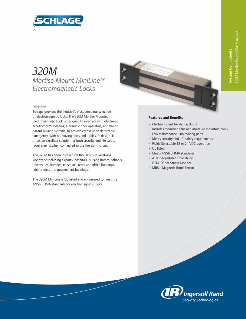
OverviewSchlage provides the industry’s most complete selection of electromagnetic locks. The 320M Mortise Mounted Electromagnetic Lock is designed to interface with electronic access control systems, automatic door operators, and fire or hazard sensing systems, to provide egress upon detectable emergency. With no moving parts and a fail safe design, it offers an excellent solution for both security and life safety requirements when connected to the fire alarm circuit.
The 320M has been installed on thousands of locations worldwide including airports, hospitals, nursing homes, schools, universities, libraries, museums, retail and office buildings, laboratories, and government buildings.
The 320M MiniLine is UL listed and engineered to meet the ANSI/BHMA standards for electromagnetic locks.
320M Mortise Mount MiniLine™ Electromagnetic Locks
Syst
em C
ompo
nent
s
320M
Mor
tise
Mou
nt M
ini M
ag L
ock
Features and Benefits
• Mortise mount for sliding doors• Includes mounting tabs and armature mounting block• Low maintenance - no moving parts• Meets security and life safety requirements• Fields Selectable 12 or 24 VDC operation• UL listed• Meets ANSI/BHMA standards• ATD - Adjustable Time Delay• DSM - Door Status Monitor• MBS - Magnetic Bond Sensor
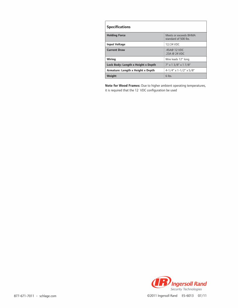
877-671-7011 • schlage.com ©2011 Ingersoll Rand ES-6013 07/11
Specifications
Holding Force Meets or exceeds BHMA standard of 500 lbs.
Input Voltage 12/24 VDC
Current Draw .45A@ 12 VDC.23A @ 24 VDC
Wiring Wire leads 12” long
Lock Body: Length x Height x Depth 7” x 1 3/8” x 1 7/8”
Armature: Length x Height x Depth 4-1/4” x 1-1/2” x 5/8”
Weight 6 lbs.
Note for Wood Frames: Due to higher ambient operating temperatures, it is required that the 12 VDC configuration be used

OverviewSchlage introduces the integrator’s an answer to retrofit needs for electromagnetics locks. These “Full Featured” electromagnetic locks are easy to stock, easy to select and easy to install. With common templating and standard features, the 40 and 70 Series Electromagnetic Locks for retrofit make sense for virtually every application.
40/70 SeriesElectromagnetic Locks
Syst
em C
ompo
nent
s
40/7
0 Se
ries
Mag
Loc
k
Features and Benefits
• Stainless steel housing - standard• Low amp draw:
- 70 Series – .12A @ 24 VDC, 25A @ 12 VDC - 40 Series – .15A @ 24 VDC, 32A @ 12 VDC
• Simplified armature installation• Strong holding forces:
- 70 Series – BHMA Grade 1 Certified 1000 lb. rating - 40 Series – BHMA Grade 1 Certified 500 lb. rating
• Universal Header Bracket (UHB)• Double magnet available with 70 series• ANSI/BHMA A156.23 Grade 1• UL 10C - 1 Hour Fire Rated• UL1034 Certified: Burglary-Resistant Electronic Locking
Mechanisms

877-671-7011 • securitytechnologies.ingersollrand.com ©2013 Ingersoll Rand 004156 01/13
Specifications 70 70TJ
Holding Force BHMA 1000 lb rating BHMA 1000 lb rating
Input Voltage 12/24 VDC 12/24 VDC
Current Draw .25A @ 12 VDC.12 @24 VDC
.25A @ 12 VDC
.12 @24 VDC
Length 8” 8”
Height 3” 3”
Depth 1 7/8” 1 7/8”
Weight 8 lbs. 12 lbs.
Certifications ANSI/BHMA A156.23, UL10C & UL1034
ANSI/BHMA A156.23, UL10C & UL1034
Filler Plates
Filler Plates Available in 628 Satin Aluminumor 335 Satin Black Finishes
1-1/4" x 1/8"
1-1/4" x 1/4"
1-1/4" x 3/8"
1-1/4" x 1/2"
1-1/4" x 5/8"
ORDERING INFORMATION
40 Single Lock70 Single Lock72 Double Lock
ACCESSORIES
HDB70 Herculite Door BracketHDB40 Herculite Door BracketUHB Universal Header BracketHEB Header Extension BracketCWB70 Concrete/Wood BracketCWB40 Concrete/Wood BracketASB70 Aluminum Spacer BracketsASB40 Aluminum Spacer BracketsDC70 Dress CoverDC40 Dress CoverOSA 1/4” offset Armature Strike
FINISHES (ACCESSORIES ONLY)
628 US28 Satin Aluminum, Anodized (standard)605 US3 Bright Brass (Dress Cover Only)335 US19 Satin Black, Anodized
Specifications 40 40TJ
Holding Force BHMA 500 lb rating BHMA 500 lb rating
Input Voltage 12/24 VDC 12/24 VDC
Current Draw .32A @ 12 VDC.15A @ 24VDC
.32A @ 12 VDC
.15A @ 24VDC
Length 8” 8”
Height 1 7/8” 1 7/8”
Depth 1 5/8” 1 5/8”
Weight 4 lbs. 4 lbs.
Certifications ANSI/BHMA A156.23, UL10C & UL1034
ANSI/BHMA A156.23, UL10C & UL1034
72 Specifications
Holding Force BHMA 1000 lb rating per door leaf
Input Voltage 12/24 VDC
Current Draw .50A @ 12 VDC.25A @ 24 VDC
Length 22”
Height 3”
Depth 1 7/8”
Weight 15 lbs.
Certifications ANSI/BHMA A156.23, UL10C & UL1034
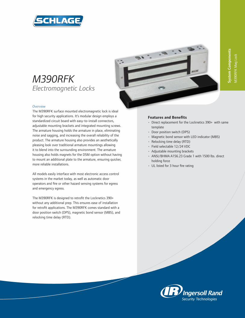
Features and Benefits • DirectreplacementfortheLocknetics390+withsame
template• Doorpositionswitch(DPS)• MagneticbondsensorwithLEDindicator(MBS)• Relockingtimedelay(RTD)• Fieldselectable12/24VDC• Adjustablemountingbrackets• ANSI/BHMAA156.23Grade1with1500lbs.direct
holdingforce• ULlistedfor3hourfirerating
OverviewTheM390RFKsurfacemountedelectromagneticlockisidealforhighsecurityapplications.It’smodulardesignemploysastandardizedcircuitboardwitheasy-to-installconnectors,adjustablemountingbracketsandintegratedmountingscrews.Thearmaturehousingholdsthearmatureinplace,eliminatingnoiseandsagging,andincreasingtheoverallreliabilityoftheproduct.Thearmaturehousingalsoprovidesanaestheticallypleasinglookovertraditionalarmaturemountingsallowingittoblendintothesurroundingenvironment.ThearmaturehousingalsoholdsmagnetsfortheDSMoptionwithouthavingtomountanadditionalplatetothearmature,ensuringquicker,morereliableinstallations.
Allmodelseasilyinterfacewithmostelectronicaccesscontrolsystemsinthemarkettoday,aswellasautomaticdooroperatorsandfireorotherhazardsensingsystemsforegressandemergencyegress.
TheM390RFKisdesignedtoretrofittheLocknetics390+withoutanyadditionalprep.Thisensureseaseofinstallationforretrofitapplications.TheM390RFKcomesstandardwithadoorpositionswitch(DPS),magneticbondsensor(MBS),andrelockingtimedelay(RTD).
M390RFKElectromagnetic Locks
Syst
em C
ompo
nent
s
M39
0RFK
Mag
Loc
k

877-671-7011 • securitytechnologies.ingersollrand.com ©2012IngersollRand00900710/12
M390RFK Electromagnetic Lock Specifications
Holding Force 1500lbs
Input Voltage (Standard Unit) 12or24VDC
Current Draw (Amps Standard Unit)
.65A@12VDC
.45A@24VDC
Height 27/8”
Length 101/2”
Width 15/8”"
Weight (approximate) 12.4lbs.
Certifications ANSI/BHMAA156.23Grade1with1500lbs.directholdingforce,andULlistedfor3hourfireratingandforburglaryresistance
Temperature 14°–140°F

Features and Benefits
• 6A @ 12/24 VDC output, field selectable with jumper
• Universal 120 -240 VAC input• Low voltage DC, regulated and filtered• Three polarized connectors for distribution boards• Fused primary input• AC input and DC output monitoring circuit
w/ LED indicators• Cover mounted AC input indication• Hinged cover w/ lock down screws• High voltage protective cover
OverviewSchlage’s comprehensive line of power supplies and option boards were designed to address the changing needs of the access control market.
Installation is simplified by utilizing a flat mounting design and polarized locking connectors for option boards. This new design eliminates the need for racks and side connectors. The flat mounting of the option boards also provides for easier access to the terminal blocks for connection of electrified devices (such as electrified strikes, electromagnetic locks, card readers, etc).
Common to the line of PS900 Series power supplies is a constant output rating at both 12v and 24v settings, universal 120 VAC to 240 VAC input, and polarized option board connectors. New fire alarm interface board mounting allows outputs to be configured as switched (power cut) or unswitched (power continues) when signal provided.
* All PS900 Series of power supplies and option boards have been tested and certified to meet UL 294.
PS9066 amp Power Supply
Photo as shown includes optional board(s)Please contact your local sales office or visit the support section on our website for configuration assistance.
Syst
em C
ompo
nent
s
PS90
6 Po
wer
Sup
ply

877-671-7011 • securitytechnologies.ingersollrand.com ©2013 Ingersoll Rand 004193 01/13
PS906 Power Supply Specifications
Specification Description
Input Voltage 120/240 VAC, 50/60 Hz, universal input
Output Voltage 6A @ 12 or 24 VDCField selectable with jumperSwitching supply, 5% regulation, 240mVpp max ripple
Enclosure Grey / Baked enamel14"H x 12"W x 4"DEight 1/2" x 3/4" KnockoutsNEMA Grade 1Hinged cover with lock down screws
Operating Temperature 32º-120º F (0º-49º C)
Certifications UL 294RoHSFCC Part 15
Option Board Compatibility 900-BB: Battery Backup900-BBK: Battery Backup Kit (backup board and battery pack)900-FA: Fire Alarm (Must be installed on distribution boards)900-2RS: 2 Relay EL Panic Device Control Board900-2RS-FA: 2 Relay Board Output with FA900-4R: 4 Relay Output Board900-4RL: 4 Relay Logic Board900-8F: Fused 8 Zone Distribution Board900-8P: PTC 8 Zone Distribution Board
AC Primary Fuse Size 6.3A, 250v, 5 x 20mm SLOW-BLOW
Battery Fuse Size 7.5A 32v ATO blade style
DC Output Protection Overload protection - current limited foldback circuit
Indicators LED indicators:-AC input (visible on outside of enclosure)-DC outputIsolated SPDT contacts to monitor AC power status
Weight (Power Supply) Approx. 9.0 lbs
Weight (Each Battery) 4.0 lbs
AC Input Termination 3 position terminal block with protective coverWire capacity: 10 AWG max.
DC Output Termination 2 position terminal blockWire capacity: 12 AWG max.
Distribution board connectors 3
Fire Alarm board connector No
Keylock Optional
OPTIONS
• Emergency Interface Relay (FA) - Must be installed on distribution boards
• Battery Backup • 2 relay QEL panic device control board• 4 relay distribution board • 4 relay distribution board with logic
- Field configurable for: • Time delay function• Auto operator
• Security interlock
• 8 fused output distribution board
• 8 PTC output distribution board
PS906
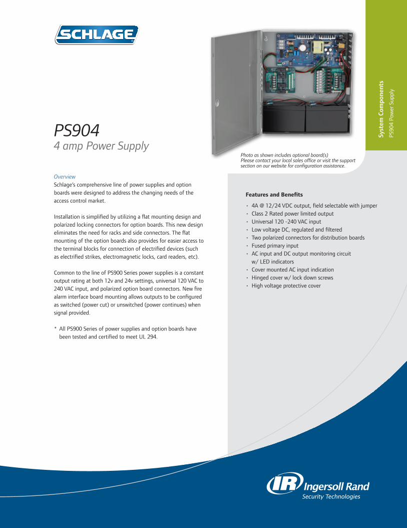
Features and Benefits
• 4A @ 12/24 VDC output, field selectable with jumper• Class 2 Rated power limited output• Universal 120 -240 VAC input• Low voltage DC, regulated and filtered• Two polarized connectors for distribution boards• Fused primary input• AC input and DC output monitoring circuit
w/ LED indicators• Cover mounted AC input indication• Hinged cover w/ lock down screws• High voltage protective cover
OverviewSchlage’s comprehensive line of power supplies and option boards were designed to address the changing needs of the access control market.
Installation is simplified by utilizing a flat mounting design and polarized locking connectors for option boards. This new design eliminates the need for racks and side connectors. The flat mounting of the option boards also provides for easier access to the terminal blocks for connection of electrified devices (such as electrified strikes, electromagnetic locks, card readers, etc).
Common to the line of PS900 Series power supplies is a constant output rating at both 12v and 24v settings, universal 120 VAC to 240 VAC input, and polarized option board connectors. New fire alarm interface board mounting allows outputs to be configured as switched (power cut) or unswitched (power continues) when signal provided.
* All PS900 Series of power supplies and option boards have been tested and certified to meet UL 294.
PS9044 amp Power Supply
Syst
em C
ompo
nent
s
PS90
4 Po
wer
Sup
ply
Photo as shown includes optional board(s)Please contact your local sales office or visit the support section on our website for configuration assistance.

877-671-7011 • securitytechnologies.ingersollrand.com ©2013 Ingersoll Rand 004194 01/13
PS904 Power Supply Specifications
Specification Description
Input Voltage 120/240 VAC, 50/60 Hz, universal input
Output Voltage 4A @ 12 or 24 VDCField selectable with jumperSwitching supply, 5% regulation, 240mVpp max ripple
Enclosure Grey / Baked enamel14"H x 12"W x 4"DEight 1/2" x 3/4" KnockoutsNEMA Grade 1Hinged cover with lock down screws
Operating Temperature 32º-120º F (0º-49º C)
Certifications UL 294Class 2RoHSFCC Part 15
Option Board Compatibility 900-BB: Battery Backup900-BBK: Battery Backup Kit (backup board and battery pack)900-FA: Fire Alarm (Must be installed on distribution boards)900-2RS: 2 Relay EL Panic Device Control Board900-2RS-FA: 2 Relay Board Output with FA900-4R: 4 Relay Output Board900-4RL: 4 Relay Logic Board900-8F: Fused 8 Zone Distribution Board900-8P: PTC 8 Zone Distribution Board
AC Primary Fuse Size 4A, 250v, 5 x 20mm SLOW-BLOW
Battery Fuse Size 7.5A 32v ATO blade style
DC Output Protection Overload protection - current limited foldback circuit
Indicators LED indicators:-AC input (visible on outside of enclosure)-DC outputIsolated SPDT contacts to monitor AC power status
Weight (Power Supply) Approx. 9.0 lbs
Weight (Each Battery) 4.0 lbs
AC Input Termination 3 position terminal block with protective coverWire capacity: 10 AWG max.
DC Output Termination 2 position terminal blockWire capacity: 12 AWG max.
Distribution board connectors 2
Fire Alarm board connector No
Keylock Optional
OPTIONS
• Emergency Interface Relay (FA) - Must be installed on distribution boards
• Battery Backup • 2 relay QEL panic device control board• 4 relay distribution board • 4 relay distribution board with logic
- Field configurable for: • Time delay function• Auto operator• Security interlock
• 8 fused output distribution board• 8 PTC output distribution board
PS904

Features and Benefits
• 2A @ 12/24 VDC output, field selectable with jumper• Class 2 Rated power limited output• Universal 120 -240 VAC input• Low voltage DC, regulated and filtered• Single polarized connector for distribution board• Fused primary input• AC input and DC output monitoring circuit
w/ LED indicators• Cover mounted AC input indication• Hinged cover w/ lock down screws• High voltage protective cover
OverviewSchlage’s comprehensive line of power supplies and option boards were designed to address the changing needs of the access control market.
Installation is simplified by utilizing a flat mounting design and polarized locking connectors for option boards. This new design eliminates the need for racks and side connectors. The flat mounting of the option boards also provides for easier access to the terminal blocks for connection of electrified devices (such as electrified strikes, electromagnetic locks, card readers, etc).
Common to the line of PS900 Series power supplies is a con-stant output rating at both 12v and 24v settings, universal 120 VAC to 240 VAC input, and polarized option board connectors. New fire alarm interface board mounting allows outputs to be configured as switched (power cut) or unswitched (power continues) when signal provided.
* All PS900 Series of power supplies and option boards have been tested and certified to meet UL 294.
PS9022 amp Power Supply
Photo as shown includes optional board(s)Please contact your local sales office or visit the support section on our website for configuration assistance.
Syst
em C
ompo
nent
s
PS90
2 Po
wer
Sup
ply
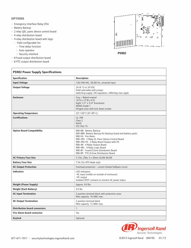
877-671-7011 • securitytechnologies.ingersollrand.com ©2013 Ingersoll Rand 004195 01/13
PS902 Power Supply Specifications
Specification Description
Input Voltage 120/240 VAC, 50/60 Hz, universal input
Output Voltage 2A @ 12 or 24 VDCField selectable with jumperSwitching supply, 5% regulation, 240mVpp max ripple
Enclosure Grey / Baked enamel14"H x 12"W x 4"DEight 1/2" x 3/4" KnockoutsNEMA Grade 1Hinged cover with lock down screws
Operating Temperature 32º-120º F (0º-49º C)
Certifications UL 294Class 2RoHSFCC Part 15
Option Board Compatibility 900-BB: Battery Backup900-BBK: Battery Backup Kit (backup board and battery pack)900-FA: Fire Alarm900-2RS: 2 Relay EL Panic Device Control Board900-2RS-FA: 2 Relay Board Output with FA900-4R: 4 Relay Output Board900-4RL: 4 Relay Logic Board900-8F: Fused 8 Zone Distribution Board900-8P: PTC 8 Zone Distribution Board
AC Primary Fuse Size 3.15A, 250v, 5 x 20mm SLOW-BLOW
Battery Fuse Size 7.5A 32v ATO blade style
DC Output Protection Overload protection - current limited foldback circuit
Indicators LED indicators:-AC input (visible on outside of enclosure)-DC outputIsolated SPDT contacts to monitor AC power status
Weight (Power Supply) Approx. 9.0 lbs
Weight (Each Battery) 4.0 lbs
AC Input Termination 3 position terminal block with protective coverWire capacity: 10 AWG max.
DC Output Termination 2 position terminal blockWire capacity: 12 AWG max.
Distribution board connectors 1
Fire Alarm board connector Yes
Keylock Optional
OPTIONS
• Emergency Interface Relay (FA)• Battery Backup • 2 relay QEL panic device control board• 4 relay distribution board • 4 relay distribution board with logic
- Field configurable for: • Time delay function• Auto operator• Security interlock
• 8 fused output distribution board• 8 PTC output distribution board
PS902

Features and Benefits
• 4A @ 12/24 VDC output, field selectable with jumper• Designed with high in rush current for powering
electrified panic devices• Universal 120 -240 VAC input• Low voltage DC, regulated and filtered• Electronic power limiting foldback circuit for
AC current overload protection• Two polarized connectors for distribution boards• Fused primary input• AC status monitor - isolated SPDT contacts• AC input and DC output LED status indicators• Cover mounted AC input indication• Hinged cover w/ lock down screws• High voltage protective cover
OverviewVon Duprin’s power supply and option boards were designed to meet the specific requirements of electrified fire exit devices.
Installation is simplified by utilizing a flat mounting design and polarized locking connectors for option boards. This new design eliminates the need for racks and side connectors. The flat mounting of the option boards also provides for easier access to the terminal blocks for connection of electrified devices (such as electrified panic devices, strikes, card readers, etc).
Common to the line of PS900 Series power supplies is a constant output rating at both 12v and 24v settings, universal 120 VAC to 240 VAC input, and polarized option board connectors. New fire alarm interface board mounting allows outputs to be configured as switched (power cut) or unswitched (power continues) when signal provided.
* All PS900 Series of power supplies and option boards have been tested and certified to meet UL 294.
PS9144 amp Power Supply (Von Duprin) Photo as shown includes optional board(s)
Please contact your local sales office or visit the support section on our website for configuration assistance.
Syst
em C
ompo
nent
s
PS91
4 Po
wer
Sup
ply

©2013 Ingersoll Rand 004101 01/13877-671-7011 • securitytechnologies.ingersollrand.com
PS914Power Supply Specifications
Specification Description
Input Voltage 120/240 VAC, 50/60 Hz, universal input
Output Voltage 4A @ 12 or 24 VDCField selectable with jumperSwitching supply, 5% regulation, 360mVpp max ripple
Enclosure Grey / Baked enamel14"H x 12"W x 4"DEight 1/2" x 3/4" KnockoutsHinged cover with lock down screws
Operating Temperature 32º-120º F (0º-49º C)
Certifications UL 294RoHSFCC Part 15Class 2
Option Board Compatibility 900-BB: Battery Backup900-BBK: Battery Backup Kit (backup board and battery pack)900-FA: Fire Alarm (Must be installed on distribution boards)900-2RS: 2 Relay Control Board900-2RS-FA: 2 Relay Board Output with FA900-4R: 4 Relay Output Board900-4RL: 4 Relay Logic Board900-8F: Fused 8 Zone Distribution Board900-8P: PTC 8 Zone Distribution Board
AC Primary Fuse Size 6.3A, 250v, 5 x 20mm SLOW-BLOW
Battery Fuse Size 7.5A 32v ATO blade style
DC Output Protection Overload protection - current limited foldback circuit
Indicators LED indicators:-AC input (visible on outside of enclosure)-DC outputIsolated SPDT contacts to monitor AC power status
Weight (Power Supply) Approx. 9.0 lbs
Weight (Each Battery) 4.0 lbs
AC Input Termination 3 position terminal block with protective coverWire capacity: 10 AWG max.
DC Output Termination 2 position terminal blockWire capacity: 12 AWG max.
Distribution board connectors 2
Fire Alarm board connector No
Keylock Optional
OPTIONS
• Fire Alarm Relay (FA) - Must be installed on distribution boards
• Battery Backup• 2 relay EL panic device control board • 2 relay QEL panic device control board• 4 relay distribution board • 4 relay distribution board with logic
- Field configurable for: • Time delay function• Auto operator• Security interlock
• 8 fused output distribution board• 8 PTC output distribution board

Features and Benefits
• Pushbuttons are available in 1-1/4”, 1-5/8”, and 2-3/4” sizes
• Two metal 1-1/4” button options: aluminum with engraved painted red “PUSH TO EXIT”, and red coated aluminum button with engraved “PUSH TO EXIT”
• 631 Push button available in 1-1/4” metal button, single gang and narrow stile.
• Two models of metal 1-1/4” button: aluminum with engraved painted red “PUSH TO EXIT” and new red coated aluminum with engraved “PUSH TO EXIT”
• Variety of colors and finishes available
OverviewSchlage Pushbuttons are used to control the ingress and/or egress of a door. The 620 and 631 Series Pushbuttons are easy to install and operate. Their standard and narrow stile plates offer ultimate flexibility. The 620 to 631 Series have multiple button configuration and finish options provide enhanced architectural appeal.
Schlage 620 and 631 Series Pushbuttons also offer significant installer friendly innovations: screw terminal connections for the momentary action models, easy to install L2/ILL optional PC board offering backlit illumination for the cone with green and red LEDs for monitoring purposes. Additional options include: Delayed Action, Double Pole Double Throw, Heavy Duty Plate, with several architectural finishes and extreme duty pushbuttons.
620/631 SeriesHeavy Duty Pushbuttons
Syst
em C
ompo
nent
s
620/
631
Serie
s H
eavy
Dut
y Pu
shbu
tton
s

877-671-7011 • schlage.com ©2013 Ingersoll Rand 003910 01/13
SF-626 Satin Chrome (standard)
SF-605 Bright Brass
SF-612 Satin Bronze
SF-613 OilRubbed Bronze
SF-625 Bright Chrome
SF-1WhitePowderCoat
SF-2BlackPowderCoat
Finishes
Selections Correspond With the Numbers to the left
1 Model621 1 1/4” Button, single gang623 1 5/8” Mushroom Button, single gang625 2 3/4” Mushroom Button, single gang631 1 1/4” Metal Button, single gang
2. ButtonGID-EX Glow-in-the-dark “PUSH TO EXIT”GID-H Glow-in-the-dark handicapped symbolGID Glow-in-the-darkRD-EX Red, “PUSH TO EXIT”RD RedGR-EX Green, “PUSH TO EXIT”GR GreenBL-H Blue, handicapped symbolBK BlackAL-EX-RD Aluminum button red coated, engraved “PUSH TO EXIT”AL-EX Aluminum button, engraved “PUSH TO EXIT”AL Aluminum button
Note: Heavy Duty Plate (HDP) 1/4” thick cast zinc standard
3. OptionsDA Delayed Action (0-60 seconds)AA Alternate Action MaintainedDP Double Pole Double Throw (not available with DA option)L2/ILL 3 LEDs -green/yellow/red concealed within opaque cone (not available for 625/625-NS models)NS Narrow Stile - Stainless Steel Plate (1 3/4” x 4 1/2”)
4. FinishSF-626 Satin Chrome (standard)SF-605 Bright BrassSF-612 Satin BronzeSF-613 Oil Satin BronzeSF-625 Bright ChromeSF-1 White Powder CoatSF-2 Black Powder Coat
621-GID-DA-SF-626
Mo
del
Bu
tton
Op
tion
s
Fin
ish
3 41 2
Ordering Information
Button Configurations
Multiple Button Configuration
1-1/4˝ Button 1-5/8˝ Mushroom Button 2-3/4˝ Mushroom Button 1-1/4˝ Metal Button
GID-EX GID-H GID RD-EX RD GR-EX GR BL-H BK
621PUSH
TOEXIT
PUSHTO
EXIT
PUSHTO
EX IT
623PUSH
TOEXIT
PUSHTO
EXIT
PUSHTO
EXIT
625PUSH
TOEXIT
PUSHTO
EXIT
AL-EX AL AL-RD-EX
621PUSH
TOEXIT
PUSHTO
EXIT
AL-EX AL AL-RD-EX
631PUSH
TOEXIT
PUSHTO
EXIT

Features and Benefits
• Single gang and narrow stile• Standard stainless steel• Momentary action (standard)• Options include LEDs, alternate action – maintained (AA)
OverviewSchlage Pushbuttons are used to control the ingress and/or egress of a door. The 700 Series Pushbuttons are easy to install and operate.
Schlage 700 Series Entry Level Pushbuttons are designed to meet commercial applications. Use with egress swinging or sliding doors that are electrically or electronically locked. 700 Series Entry Level Pushbuttons are available for single gang and narrow stile applications. The 709 model includes backlit buttons with “PUSH TO EXIT” or Handicap Symbol to meet ADA requirements.
700 Series Pushbuttons
Syst
em C
ompo
nent
s
700
Serie
s Pu
shbu
tton
s

877-671-7011 • securitytechnologies.ingersollrand.com ©2011 Ingersoll Rand 003911 12/11
700 Specifications
701 Pushbutton
Contact Ratings 5A @ 30VAC/UDC, momentary SPDT contacts
Wire Leads 20 awg – 6” long
709 Pushbutton
Contact Ratings 5A @ 30VAC/UDC, momentary SPDT contacts
Wire Leads 20 awg – 8” long
Input requirements with LED option
Voltage 12/24 VDC
Current Draw 30 mA
Wire Leads 24 awg – 6” long
Input requirements with ILL option
Voltage 12 VDC for 709 series only 24 VDC for 701/709 series
ORDERING INFORMATION
701RD 7/8” Red Mushroom Button
701BK 7/8” Black Mushroom Button
701RD EX 5/8” Red Button - Engraved “PUSH TO EXIT”
701RD EX ILL 5/8” Red Button – Illuminated “PUSH TO EXIT”
709RD EX ILL 2” Red Square - Illuminated “PUSH TO EXIT”
709GR EX ILL 2” Green Square – Illuminated “PUSH TO EXIT”
709BLH ILL 2” Blue Square – Illuminated Handicapped Symbol
OPTIONS
L2 Two LEDs, red and green, dual voltage
AA Alternate Action – Maintained (not available for 709 models)
NS Narrow Stile plate (not available for 709 models)

Features and Benefits
• Surface mount in a standard 3-gang enclosure• Compatible with all Fail Safe type electronic locking
systems• An effective alternative to the standard pull box• Stainless steel standard finish• Models with LED or audible alarm• Clearly marked signage indicating purpose of the
release
OverviewSchlage 740 Series Emergency Break Glass Releases are designed for use as emergency releases of non-designated egress doors such as in individual and partitioned laboratories, secluded testing areas, or other isolated work rooms that are purposely provided with exit doors. In perimeter protection systems that involve the central control of electric locking devices, an on-site emergency release may be required. The “break glass” concept may be preferred over the pull station, because it is less vulnerable to misuse or tamper actuation.
The 740 Series Emergency Break Glass units consist of a replacement Break glass cartridge, that normally holds the plunger-activated switch depressed until the cartridge lens is broken. When the lens is broken the plunger moves forward and alters the switch contact position. Four replacement lens disks are provided with each assembly. The small hammer is attached to the Break Glass Assembly via a mounting clip along with a 12” chain, to insure it will not detach from the assembly.
740 Series Emergency Break Glass Releases
Syst
em C
ompo
nent
s
740
Emer
genc
y R
elea
se

877-671-7011 • schlage.com ©2011 Ingersoll Rand ES-5977 07/11
740 Specifications - Contact Box from “Z” switch
Contact Rating
6A @ 120 VACNormally Open (NO)Normally Closed (NC) contacts with color-coded leads
LED 12/24 VDC
Horn 3-18 mA
Input 6-28 VDC
Decibles 80 dB @ 2ft.
ORDERING INFORMATION
740 – Includes break glass switch assembly and hammer mounted to a silk-screened 3-gang stainless switch plate
741 – Includes an attached indicator light with red lens
742 – Includes a Sonalert horn for 6-24 VDC operation attached to the plate

Features and Benefits
• Surface mount application• Choice of maintained or momentary action• Compact size• Recommended for concealed desk application
OverviewThe 660 Series Mini Station Control is designed for concealed desk application, and it is used to release an electric or electronic locking mechanism from a remote location. The 660 Series Mini Station Control is mounted in a mini aluminum box, 2” x 2” x 1”. The 660 is available with a momentary action pushbutton or maintained action toggle switch. Both can be surface mounted. A typical application is under a desk to release an entrance door
660 SeriesMini Station Control
Syst
em C
ompo
nent
s
660
Serie
s M
ini S
tatio
n Co
ntro
l

877-671-7011 • schlage.com ©2013 Ingersoll Rand 003912 01/13
ORDERING INFORMATION
660-T4 SPDT Maintained Toggle
660-PB PB SPDT Momentary Pushbutton (DPDT Optional)
Specifications
Switch contact rating: 6 AMP @ 120 VAC
Length 2”
Width 2”
Height 1
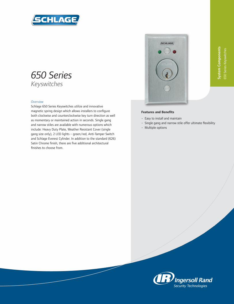
Features and Benefits
• Easy to install and maintain• Single gang and narrow stile offer ultimate flexibility• Multiple options
OverviewSchlage 650 Series Keyswitches utilize and innovative magnetic spring design which allows installers to configure both clockwise and counterclockwise key turn direction as well as momentary or maintained action in seconds. Single gang and narrow stiles are available with numerous options which include: Heavy Duty Plate, Weather Resistant Cover (single gang size only), 2 LED lights – green/red, Anti-Tamper Switch and Schlage Everest Cylinder. In addition to the standard (626) Satin Chrome finish, there are five additional architectural finishes to choose from.
650 Series Keyswitches
Syst
em C
ompo
nent
s
650
Serie
s Ke
ysw
itche
s

877-671-7011 • schlage.com ©2011 Ingersoll Rand ES-5978 07/11
SpecificationsStandard keyswitch• 5 amp@250 VAC,• dual voltage,• SPDT contactsATS switch closes when cover is on 0.025A@28VDCLED Indicator Lights operate at 12/24 VDC 0.025A@28VDC
Innovative magnetic spring technology allows installers to configure models in seconds
MOMENTARY ACTION MAINTAINED ACTION
Momentary action - magnet dot side up. Maintained action - magnet dot side down.
ORDERING INFORMATION
653-04 SPDT maintained single direction653-05 SPDT momentary single direction653-14 DPDT maintained single direction653-15 DPDT momentary single direction653-1414 (2) DPDT maintained bi-direction653-1415 DPDT maintained x DPDT momentary653-1515 (2) DPDT momentary bi-direction653-041 SPDT maintained x key remove one position653-0404 (2) SPDT maintained bi-direction653-0405 SPDT maintained x SPDT momentary653-141 DPDT maintained x key remove one position653-0505 (2) SPDT momentary bi-direction
OPTIONS
L2 2 LEDs green and red, dual voltageNS Narrow Stile - stainless steel plate (1 3/4” x 4 1/2”)ATS Anti-Tamper SwitchHDP Heavy Duty Plate 1/4” thick cast zinc (standard 626
Satin Chrome Finish with anti tamper plugs)WP Weather Resistant Cover fits 1 1/8” cylinder only
(not available with NS and L2 Options)CYL 1-1/4” Schlage Everest® Mortise Cylinder &
1/8” spacer ring (keyed different)CYL-KA 1-1/4” Schlage Everest Mortise Cylinder &
1/8” spacer ring (keyed alike)
Note: 650 Series Keyswitches operate with either a 1-1/8” or 1-1/4” cylinder having a straight type cam. 1-1/4” cylinders require a 1/8” blocking/spacer ring (included with the CYL and CYL-KA options).
FINISH
SF-626 Satin Chrome (standard)SF-605 Bright BrassSF-612 Satin BronzeSF-613 Oil Satin BronzeSF-625 Bright ChromeSF-2 Black Powder Coat
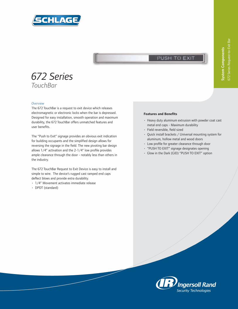
Features and Benefits
• Heavy duty aluminum extrusion with powder coat cast metal end caps - Maximum durability
• Field reversible, field sized• Quick install brackets / Universal mounting system for
aluminum, hollow metal and wood doors• Low profile for greater clearance through door• “PUSH TO EXIT” signage designates opening• Glow in the Dark (GID) “PUSH TO EXIT” option
OverviewThe 672 TouchBar is a request to exit device which releases electromagnetic or electronic locks when the bar is depressed. Designed for easy installation, smooth operation and maximum durability, the 672 TouchBar offers unmatched features and user benefits.
The “Push to Exit” signage provides an obvious exit indication for building occupants and the simplified design allows for reversing the signage in the field. The new pivoting bar design allows 1/4” activation and the 2-1/4” low profile provides ample clearance through the door - notably less than others in the industry.
The 672 TouchBar Request to Exit Device is easy to install and simple to wire. The device’s rugged cast ramped end caps deflect blows and provide extra durability. • 1/4” Movement activates immediate release• DPDT (standard)
672 Series TouchBar
Syst
em C
ompo
nent
s
672
Serie
s R
eque
st-t
o-Ex
it B
ar

877-671-7011 • securitytechnologies.ingersollrand.com ©2011 Ingersoll Rand 003909 12/11
672 TouchBar Electrical Specifications
Input Voltage 12 or 24 VDC maximum current draw .25 Amps
Switch DPDT contacts rated 4 Amps @ 30 VDC
Wiring 6 Conductor Cable - 20 AWG (standard)
ORDERING INFORMATION
Door Size36”, 42” or 48”
Finishes628 Satin Anodized Aluminum (standard)313 Dark Satin Bronze Anodized Aluminum
TouchPadsRD Black with red “PUSH TO EXIT”GID Black with Glow in the Dark “PUSH TO EXIT”
HandingRHR Right Hand ReverseLHR Left Hand Reverse -Field Reversible
OptionsWDSexnut door kit for heavy duty wood door and hollow metal door applications
AR18” x 1/2” armored door cord (less wire)
SHKAluminum door mounting shim kit includes brackets shims and screws for narrow stile aluminum doors.*
* Note: Screw pack has self-drilling and self-tapping screws for aluminum and wood door applications and rivnuts for hollow metal door applications.

Features and Benefits
• Heavy duty aluminum extrusion with cast metal end caps - Maximum durability
• Field reversible, field sized• Quick install brackets / Universal mounting system for
aluminum, hollow metal and wood doors• Low profile for greater clearance through door• “PUSH TO EXIT” signage designates opening• Glow in the Dark “PUSH TO EXIT” option
OverviewThe 692 SmartBar is an electronic switching device with no moving parts, which serves as a non-latching request to exit bar at and egress door. It allows one motion egress at doors equipped with electromagnetic or electronic locks, with “no prior knowledge” required by the user. Touching the SmartBar at any point on the bar activates internal circuitry which controls power to the locking device. No moving parts results in low maintenance and long life.
The 692 SmartBar provides two directionally opposed infrared detection circuits to sense an exit request. As a person touches the bar the light beam is broken. The patent pending redundant system provides a high level of life safety and peace of mind to the end user.
An audible alarm is standard. This feature provides a security alarm to alert when there is a prolonged unlocked condition caused by a continued break in the light beam. This feature is desirable in applications requiring monitoring of security conditions or delayed egress. • Dual Infrared detection circuits – patent pending• No Moving Parts – One Motion Egress• Audible alarm standard, alerts prolonged unlock condition• DPDT relay standard – single access control panel or
auxiliary device
692 SeriesSmartBar™
Syst
em C
ompo
nent
s
692
Serie
s R
eque
st-t
o-Ex
it B
ar

877-671-7011 • schlage.com ©2013 Ingersoll Rand 003904 01/13
692 SmartBar Electrical Specifications
Input Voltage 12 or 24 VDC maximum current draw .5 Amps
Switch DPDT contacts rated 4 Amps @ 30 VDC
Wiring 8 Conductor Cable - 20 AWG (standard)
ORDERING INFORMATION
Door Size36”, 42” or 48”
Finishes628 Satin Anodized Aluminum (standard)313 Dark Satin Bronze Anodized Aluminum
TouchPadsRD Black with red “PUSH TO EXIT”GID Black with Glow in the Dark “PUSH TO EXIT”
HandingRHR Right Hand ReverseLHR Left Hand Reverse -Field Reversible
OptionsWDSexnut door kit for heavy duty wood door and hollow metal door applications
SHKAluminum door mounting shim kit includes brackets shims and screws for narrow stile aluminum doors.*
* Screw pack has self-drilling and self-tapping screws for aluminum and wood door applications and rivnuts for hollow metal door applications.
Note: 18” x ½” Armoured door cord shipped standard

Overview800 Series Local & Remote Monitoring StationThe 800 Series monitoring stations can provide monitoring for a single zone with up to 2 LED indicators.
801 Series Local & Remote Monitoring StationsThe 801 unit includes an audible and visual indication of lock status and delay activation. Interfaces with electromagnetic locks with magnetic bond sensor (MBS) option. Unit mounts in a standard single gang electrical box.
The 801-KS fulfills a code requirement stating that a local signal assures users that a delayed egress system is functional. The unit includes an audible and visual indication of lock status and delay activation. Provides a Single Pole, Double Throw (SPDT) momentary x SPDT maintained contact arrangement keyswitch for legal release and reset of the system, which interfaces with a standard 1-1/4” mortise cylinder with standard straight cam. Interfaces with electromagnetic locks with magnetic bond sensor (MBS) option. Unit mounts in a standard double gang electrical box.
800 SeriesRemote and Local Monitoring Stations
Features and Benefits
800 Series Local & Remote Monitoring Station
• Up to 2 LED Indicators
801 Series Local & Remote Monitoring Stations
• 801-KS Option
Syst
em C
ompo
nent
s
800
Serie
s M
onito
ring
Stat
ions

877-671-7011 • schlage.com ©2011 Ingersoll Rand ES-5988 07/11
800 Specifications
Operating Power: 12/24 VDC
LED Operating Power: 6-28 VDC
LED Current Draw: 30 mA ea.
Audible Input: 10-28 VDC
Audible Current Draw: 3-14 mA
Decibel Rating: 80 dB @ 2 ft.
Single Gang Unit
Length: 2-3/4"
Width: 1-1/2"
Height: 4-1/2"
Finish: Stainless Steel
800L1 One (1) LED Indicator - red, green, and amber
800L2 Two (2) LED Indicators - red, green, and amber
800A Audible Sounder
801 Specifications
Operating Power: 12/24 VDC
LED Operating Power: 6-28 VDC
LED Current Draw: 30 mA ea.
Audible Input: 10-28 VDC
Audible Current Draw: 3-14 mA
Decibel Rating: 80 dB @ 2 ft.
Single Gang Unit801* Local or Remote Monitoring System
Length: 2-3/4"
Width: 1-1/2"
Height: 4-1/2"
Finish: Stainless Steel
Double Gang Unit801-KS* Local or Remote Monitoring System with Keyswitch (less cylinder)
Length: 4-9/16"
Width: 1-15/16"
Height: 4-1/2"
Finish: Stainless Steel
Keyswitch Contacts: 5A/250 VAC
*Note: 801/801-KS requires MBS on locking device.
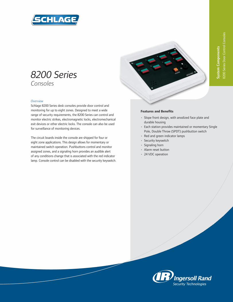
OverviewSchlage 8200 Series desk consoles provide door control and monitoring for up to eight zones. Designed to meet a wide range of security requirements, the 8200 Series can control and monitor electric strikes, electromagnetic locks, electromechanical exit devices or other electric locks. The console can also be used for surveillance of monitoring devices.
The circuit boards inside the console are shipped for four or eight zone applications. This design allows for momentary or maintained switch operation. Pushbuttons control and monitor assigned zones, and a signaling horn provides an audible alert of any conditions change that is associated with the red indicator lamp. Console control can be disabled with the security keyswitch.
8200 SeriesConsoles
Features and Benefits
• Slope front design, with anodized face plate and durable housing
• Each station provides maintained or momentary Single Pole, Double Throw (SPDT) pushbutton switch
• Red and green indicator lamps• Security keyswitch• Signaling horn• Alarm reset button• 24 VDC operation
Syst
em C
ompo
nent
s
8200
Ser
ies
Doo
r Con
trol
Con
sole
s

877-671-7011 • schlage.com ©2011 Ingersoll Rand ES-5983 07/11
Specifications
Switches(momentary or maintained)
1.0 amps 24 VDC
Lamps #85 Red/Green 04 amps @24 VDC
Terminal Block 18/22 gauge wire
Alarm output 0.5 amps @ 24 VDC (breaker protected)
Temperature Range 32° to 120°F (0° to 49°C)
Input Voltage 24 VDC, ±15%
SYSTEM DESIGN GUIDE
There are a number of applications where and 8200 Series Console is used to monitor and control multiple door openings. It is ideal for use at a guard or nurse station. (An example of a riser diagram for a two door nurse’s station console is shown below.)
DESCRIPTION OF SYSTEM OPERATION
Two single doors, each normally closed and secured by a magnetic lock. Magnetic lock to include Magnetic Bond Sensor (MBS) for remote monitoring of secure/not-secure condition. Legal access to be provided by keypad system. Egress to be provided by touch sensitive exit bars. Remote control and monitoring to be by a slope front desktop console. Each of two stations shall provide a momentary pushbutton switch for legal release, a red indicator for “not-secure” condition and a green indicator for “secure” condition.
Console
Power Supply
Controller
Mag Lock Mag Lock
Exit Device Exit DeviceReader/Key Card
Reader/ Key Card
ControllerRiser Diagram
ORDERING INFORMATIONLast Digit Indicates Number of Zones
4 Station Console 8 Station Console8204 8208
PUSHBUTTON FUNCTIONSelect pushbutton function by zone.Select M (momentary) or A (alternate action, maintain) for each zone.
1 2 3 4 5 6 7 88204 _ _ _ _8208 _ _ _ _ _ _ _ _
ACCESSORIES
Field Installable Push Buttons
8200MS – Momentary Switch Assembly
8200 MA – Alternate Action (Maintained) Switch Assembly
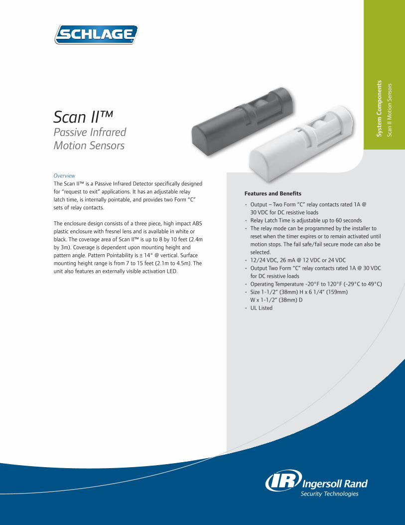
Features and Benefits
• Output – Two Form “C” relay contacts rated 1A @ 30 VDC for DC resistive loads
• Relay Latch Time is adjustable up to 60 seconds• The relay mode can be programmed by the installer to
reset when the timer expires or to remain activated until motion stops. The fail safe/fail secure mode can also be selected.
• 12/24 VDC, 26 mA @ 12 VDC or 24 VDC• Output Two Form “C” relay contacts rated 1A @ 30 VDC
for DC resistive loads• Operating Temperature -20°F to 120°F (-29°C to 49°C)• Size 1-1/2” (38mm) H x 6 1/4” (159mm)
W x 1-1/2” (38mm) D• UL Listed
OverviewThe Scan II™ is a Passive Infrared Detector specifically designed for “request to exit” applications. It has an adjustable relay latch time, is internally pointable, and provides two Form “C” sets of relay contacts.
The enclosure design consists of a three piece, high impact ABS plastic enclosure with fresnel lens and is available in white or black. The coverage area of Scan II™ is up to 8 by 10 feet (2.4m by 3m). Coverage is dependent upon mounting height and pattern angle. Pattern Pointability is ± 14° @ vertical. Surface mounting height range is from 7 to 15 feet (2.1m to 4.5m). The unit also features an externally visible activation LED.
Scan II™ Passive Infrared Motion Sensors
Syst
em C
ompo
nent
s
Scan
II M
otio
n Se
nsor
s

877-671-7011 • schlage.com ©2011 Ingersoll Rand ES-5984 07/11
Front View
Standard PatternShown wall mounted, angled 14° down.
Side View
Standard PatternShown wall mounted, angled 14° down.
ORDERING INFORMATION
Scan II – B BlackScan II – W White

Features and Benefits
• All horns are off white in color and come with a skirt for a clean finish.
• Designed for indoor use only.• Available in four models:
- 1910-1 Horn 12/24 VDC - 1910S-1 Horn with Strobe 24 VDC - L1910-1 Horn with Latching 24 VDC - L1910S-1 Horn with Strobe and Latching 24 VDC
• Current Draw: - Less than 14 mA @ 12 V - Less than 28 mA @ 24 V - Less than 71 mA @ 24 V, with strobe
• Operating Temperature: 32ºF to 120ºF• Anechoic Room @30 V 102 dba• UL Reverbrant Room @30 V 88 dba
OverviewElectric horns are designed for use as an immediate local audible warning device incorporated in a security system. 1910 Selica Horns have eight combinations of volume, tone, and code that are easily user configurable. Strobe and latching combinations are also available.
Units are flush and surface mountable using a standard one or two gang electrical box. Surface and flush mounting kits are included with all horns.
Electronic Horns
Syst
em C
ompo
nent
s
Elec
tric
Hor
ns

877-671-7011 • schlage.com ©2011 Ingersoll Rand ES-5985 07/11
ORDERING INFORMATION
1910-1 12/24 VDC Horn1910S-1 24 VDC Horn with StrobeL1910-1 24 VDC Horn with LatchingL1910S-1 24 VDC Horn with Strobe and Latching

OverviewDoor position switches are used to detect the open or closed status of an opening and then send this status to a control panel. They come in a variety of shapes and sizes and are designed for monitoring door positions, roof hatches, gates etc.
Door PositionSwitches
Concealed SPDT Magnetic Switches
For Wood Doors and Frames0.3 Amps @ 30 VDC
For Hollow Metal Doors and Frames0.3 Amps @ 30 VDC
For Wood Doors and Metal Frames0.3 Amps @ 30 VDC
7764
Concealed/Flush Mount Magnetic SwitchesFor aluminum, wood and hollow metal doors 0.25 Amps @ 30 VDC UL Listed
Surface Mount Magnetic SwitchesFor aluminum, wood and hollow metal doors 0.25 Amps @ 30 VDC UL Listed
7766
Syst
em C
ompo
nent
s
Doo
r Pos
ition
Sw
itche
s
679-05 WD
679-05 HM
679-05
674-OHOverhead Door, Floor Mount Magnetic Switch

877-671-7011 • schlage.com ©2011 Ingersoll Rand ES-5986 07/11
ORDERING INFORMATION
674-OH Overhead Door Floor Mount679-05 Wood Door and Frame679-05HM Hollow Metal Door and Frame679-05WD Wood Door and Metal Frame7764 Concealed/Flush Mount7766 Surface Mount

OverviewUsed when installing electric exit devices or electric locks, armored door cords provide a simple and economical solution for transferring power from frame to door.
Armored Door Cords with Caps
Syst
em C
ompo
nent
s
Arm
ored
Doo
r Cor
ds

877-671-7011 • securitytechnologies.ingersollrand.com
Specifications
Acceptable Wire Size Combinations
• Five 18 gauge• Two 18 gauge and four 20 gauge• Two 18 gauge and seven 22 gauge• Seven 20 gauge• Twelve 22 gauge
5/16” interior diameter; 3/8” outside diameter flexible door cord
Model Description
788-12 12” x 3/8” less wires (inswinging)788C-12 12” x 3/8” with 20” 4-Conductor wire, 20 gauge wire788-18 18” x 3/8” less wires (outswinging)788C-18 18” x 3/8” with 26” 4-Conductor wire, 20 gauge wire
3/8” interior diameter; 1/2” outside diameter flexible door cord
Acceptable Wire Size CombinationsModel Description
798-12 12” x 1/2” less wires (inswinging)798C-12 12” x 1/2” with 20” 4-Conductor wire, 20 gauge wire798-18 18” x 1/2” less wires (outswinging)798C-18 18” x 1/2” with 26” 4-Conductor
wire, 20 gauge wire
©2012 Ingersoll Rand 005006 02/12
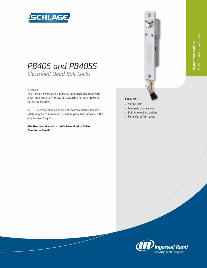
Features
• 12/24V DC • Magnetic door sensor• Built in relocking option• Fail-safe, or fail-secure
OverviewThe PB405 PowerBolt is a mortise, right angle deadbolt with a .61” bolt and a .67” throw. It is available fail safe PB405 or fail secure PB405S.
NOTE: Electromechanical locks not recommended where life safety may be compromised, or where panic bar hardware is the only means of egress.
Mortise mount electric bolts furnished in Satin Aluminum Finish.
PB405 and PB405S Electrified Dead Bolt Locks
Syst
em C
ompo
nent
s
PB40
5 &
PB
405S
Pow
er B
olts

877-671-7011 • securitytechnologies.ingersollrand.com ©2011 Ingersoll Rand 005011 12/11
Specifications
PB405 Electric Dead Bolt Lock (Fail Safe)
1. Door sensor 2. 12V/24V DC 3. Current Draw: 0.9A @ 12 VDC, 0.45A @ 24 VDC;
12/24 VDC dual voltage, field selectable 4. Fail-safe type (Power to lock) 5. Built-in Relocking option 6. Operation delay time: 0 sec., 3 sec., 5 sec., 9 sec. 7. Bolt diameter: 0.61 in 8. Bolt throw: 0.67 in 9. Weight: 1.9lbs 10. Dimension: 7.87 in (L) x 1.26 in (W) x 1.57 in (D)
PB405S Electric Dead Bolt Lock (Fail Secure)
1. Door sensor 2. 12V/24V DC. 3. Current Draw: 0.9A @ 12 VDC, 0.45A @ 24 VDC;
12/24 VDC dual voltage, field selectable 4. Fail-secure type (Power to open.), MOV surge protection. 5. Operation delay time: 0 sec., 3 sec., 5 sec., 9 sec. 6. Built-in relocking option 7. Bolt diameter: 0.61 in 8. Bolt throw: 0.67 in 9. Weight: 1.9lbs 10. Dimension: 7.87 in (L) x 1.26 in (W) x 1.57 in (D)
ORDERING INFORMATION
405 - Rectangular Front, Fail Safe
405S - Rectangular Front, Fail Secure
Fail Secure Lock – Requires power to unlock
Fail Safe Lock – Requires power to lock

App
endi
x
Appendix
This section of the Electronic Access Control catalog includes:• Resource Guides• Solution Sheets• Wiring Diagrams

App
endi
x
877-671-7011 • securitytechnologies.ingersollrand.com ©2011 Ingersoll Rand 005138 09/11
THIS PAGE IS INTENTIONALLY BLANK.

Training Location:
Web & Interactive Tools Location:
Literature Location:
– Utilize “search” on AD-Series page to locate each piece using the description in parentheses • Benefits Brochure (Benefits Brochure) • Selection Guide (Selection Guide) • Mini-Brochure (ES-5542) • Market Application Sheets – Higher Education (ES_5528) – K-12 (ES_5529) – Healthcare (ES_5527)
• Datasheets – AD-200 (004442) – AD-250 (004436) – AD-300 (004448) – AD-400 (004446) – AD-301 FIPS 201-1 Compliant (004869) – AD-401 FIPS 201-1 Compliant (004870) – SUS on HHD (004443) – Proximity or Smart Keyfobs (004227) – Exit Trim Companion Sheet (found in technical library)
• Service and Support: includes Contact Us page, 150 FAQ’s, & Technical Library • Interactive Benefits Overview: Learn about the flexible, scalable, and adaptable features • Interactive Product Tour: View product highlights and features in the 360° tour • Interactive Product Selector: Configure an AD-Series lock to fit your needs
• 27 AD-Series “How to Videos” are now available to view on the AD-Series YouTube Channel – http://www.youtube.com/user/SchlageAD • Specialty formatted videos are available to download to your HHD at: – www.schlage.com/ad-series > Service & Support > Download “How To” Videos
• AD-Series e-Learning Courses on IRU – Today Meets Tomorrow - value proposition – Explore the Details - product information – Make the Case - return on investment
For guest access enter your username and password. First time users click on “Don’t have a login?” for registration.
www.schlage.com/ad-series
www.schlage.com/ad-series
YouTube and IRU
Mini-Brochure
Selection Guide
Product Selector Benefits Overview Product Tour
http://schlage.com/onlinecourses
CLICK HERE
CLICK HERE
CLICK HERE
AD-Series Resources

877-671-7011 • securitytechnologies.ingersollrand.com
Distributor & Channel Partner Tools Location:
Technical Documents Location:
AD-Series Resources
Web & Interactive tools
• The Technical Library contains: • Templates – Organized by Cylindrical, Mortise, Mortise Deadbolt, and 993/Exit – Retrofit Overlay Template available • User Guides (found under Installation Manuals) – Organized by AD-400, AD-300, AD-250, AD-200, AD-Series Exit Trim, PIM400-TD2, PIM400-485, HHD, SUS, and PIB300-2D • Installation Manuals – Organized by Cylindrical, Mortise, and Exit • Application Notes/Technical Bulletins • Firmware & Software – AD Firmware Package – Schlage SUS Software – Note: Check for updates on a regular basis • Also found within Technical Library – Brochures/Sales Materials – Datasheets and Solution Sheets – How To Videos – A&E Specs and More
– Registered Users: http://partnerlink-admin.ingersollrand.com/Pages/AD-Series.aspx– New Users: Go to http://partnerlink.ingersollrand.com and click on the new user link • AD-Series can be found at: PartnerLink > Product Info > Access Control &Video > AD-Series – Tools not available on the public web: • Parts Guides • Cross-Reference Tools • Weights & Dimensions • Pricebooks • PartnerLink Connection Newsletter • And more
• “How To” App for AD-Series
www.schlage.com/support
PartnerLink
CLICK HERE
CLICK HERE
©2012 Ingersoll Rand 004085 11/12
Additional Resources
FREE DOWNLOAD CLICK HERE
FREE DOWNLOAD CLICK HERE
• EAC Catalog http://epub.securitytechnologies.com
• Security Technologies Page: http://w3.securitytechnologies.com/irst/Pages/default.aspx
• AD-Series Software Integrations: http://partnerlink-admin.ingersollrand.com/ProductInformation/ AccessControl/AD-Series/Pages/AD-Series.aspx

Training Location:
Web & Interactive Tools Location:
Literature Location:
• Brochures • Flipbook (004122) • Mini Brochure (ES-5916)• Data Sheets • CO-100 (004186) • CO-200 (004185) • CO-250 (004184) • Schlage Utility Software (SUS) on Handheld Device (HHD) (004443) • Proximity or Smart KeyFobs (004227) • Exit Trim Companion Sheet (004183)
www.schlage.com/support
CLICK HERE
CO-Series Resources
Mini Brochure
• CO-Series web page can be found at: schlage.com > For Your Business > Products > Locks > Electronic Locks & System Components > CO-Series• Interactive Product Selector• Service and Support: Includes Contact Us page, FAQ’s & Technical Library• Interactive Product Tour: View product highlights and features in the 360° product tour
www.schlage.com
CLICK HERE
Product Selector FAQ
• CO-Series e-Learning Courses on Ingersoll Rand University (IRU) • Get to Know the CO
schlage.com/onlinecoursesFor guest access enter your username and password.First time users click on “Don’t have a login?” for registration.
IRU and CO Web Page
Flip Book
360° Product Tour
CLICK HERE• CO-Series How To Videos
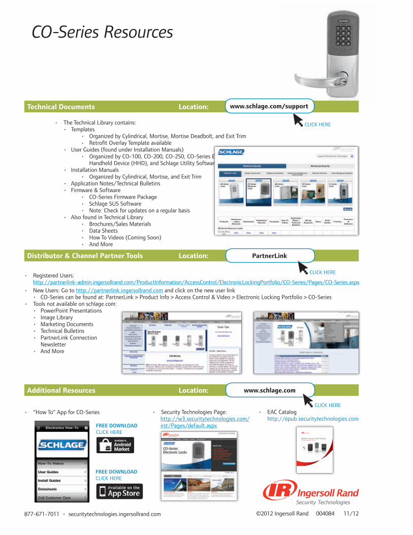
877-671-7011 • securitytechnologies.ingersollrand.com
Additional Resources Location:
Distributor & Channel Partner Tools Location:
Technical Documents Location:
CO-Series Resources
• The Technical Library contains: • Templates • Organized by Cylindrical, Mortise, Mortise Deadbolt, and Exit Trim • Retrofit Overlay Template available • User Guides (found under Installation Manuals) • Organized by CO-100, CO-200, CO-250, CO-Series Exit Trim, Handheld Device (HHD), and Schlage Utility Software (SUS) • Installation Manuals • Organized by Cylindrical, Mortise, and Exit Trim • Application Notes/Technical Bulletins • Firmware & Software • CO-Series Firmware Package • Schlage SUS Software • Note: Check for updates on a regular basis • Also found in Technical Library • Brochures/Sales Materials • Data Sheets • How To Videos (Coming Soon) • And More
©2012 Ingersoll Rand 004084 11/12
• Registered Users: http://partnerlink-admin.ingersollrand.com/ProductInformation/AccessControl/ElectronicLockingPortfolio/CO-Series/Pages/CO-Series.aspx• New Users: Go to http://partnerlink.ingersollrand.com and click on the new user link • CO-Series can be found at: PartnerLink > Product Info > Access Control & Video > Electronic Locking Portfolio > CO-Series• Tools not available on schlage.com: • PowerPoint Presentations • Image Library • Marketing Documents • Technical Bulletins • PartnerLink Connection Newsletter • And More
PartnerLink
• Security Technologies Page: http://w3.securitytechnologies.com/
irst/Pages/default.aspx
www.schlage.com
www.schlage.com/support
CLICK HERE
CLICK HERE
CLICK HERE
• “How To” App for CO-Series
FREE DOWNLOAD CLICK HERE
FREE DOWNLOAD CLICK HERE
• EAC Catalog http://epub.securitytechnologies.com
Electronic Access Control Catalogfor Open Architecture Solutions
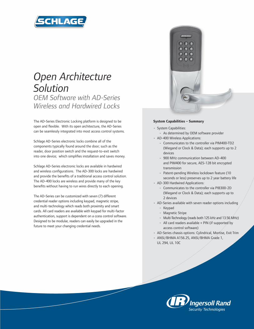
System Capabilities – Summary
• System Capabilities: - As determined by OEM software provider
• AD-400 Wireless Applications: - Communicates to the controller via PIM400-TD2
(Wiegand or Clock & Data); each supports up to 2 devices
- 900 MHz communication between AD-400 and PIM400 for secure, AES-128 bit encrypted transmission
- Patent-pending Wireless lockdown feature (10 seconds or less) preserves up to 2 year battery life
• AD-300 Hardwired Applications: - Communicates to the controller via PIB300-2D
(Wiegand or Clock & Data); each supports up to 2 devices
• AD-Series available with seven reader options including - Keypad - Magnetic Stripe - Multi-Technology (reads both 125 kHz and 13.56 MHz) - All card readers available + PIN (if supported by
access control software)• AD-Series chassis options: Cylindrical, Mortise, Exit Trim• ANSI/BHMA A156.25, ANSI/BHMA Grade 1,
UL 294, UL 10C
The AD-Series Electronic Locking platform is designed to be open and flexible. With its open architecture, the AD-Series can be seamlessly integrated into most access control systems.
Schlage AD-Series electronic locks combine all of the components typically found around the door; such as the reader, door position switch and the request-to-exit switch into one device; which simplifies installation and saves money.
Schlage AD-Series electronic locks are available in hardwired and wireless configurations. The AD-300 locks are hardwired and provide the benefits of a traditional access control solution. The AD-400 locks are wireless and provide many of the key benefits without having to run wires directly to each opening.
The AD-Series can be customized with seven (7) different credential reader options including keypad, magnetic stripe, and multi-technology which reads both proximity and smart cards. All card readers are available with keypad for multi-factor authentication, support is dependent on a ccess control software. Designed to be modular, readers can easily be upgraded in the future to meet your changing credential needs.
Open Architecture Solution OEM Software with AD-Series Wireless and Hardwired Locks

SYST
EM A
RCH
ITEC
TUR
E
OEM System
OEM System
OEM Controller with Wiegand Protocol Port
OEM Controller
900 MHz
900 MHz
AD-400 Wireless Devices(up to 2 Devices)
AD-400 Wireless Devices(up to 2 Devices)
PIM400-TD2(Panel Interface Module)
PIM400-TD2(Panel Interface Module)
AD-400 Wireless System utilizing Wiegand Protocol Port or RS485 Port
OEM System
OEM System
OEM Controller with Wiegand Protocol Port
OEM Controller
L AN
WIEGAND OR CLOCK & DATA
PROTOCOL
WIEGAND OR CLOCK & DATA
PROTOCOL
WIEGAND OR CLOCK & DATA
PROTOCOL
WIEGAND OR CLOCK & DATA
PROTOCOL
OEM PROTOCOL
PORT
RSI PROTOCOL
RSI PROTOCOL
OEM PROTOCOL
PORT
READER DATA
READER DATA
READER DATA
READER DATA
REQUEST TO EXIT
REQUEST TO EXIT
REQUEST TO EXIT
REQUEST TO EXIT
DOOR POSITION
DOOR POSITION
DOOR POSITION
DOOR POSITION
TROUBLE
TROUBLE
TROUBLE
TROUBLE
LOCK RELAY
LOCK RELAY
LOCK RELAY
LOCK RELAY
RS485
RS485
AD-300 Hardwired Devices(up to 2 Devices)
AD-300 Hardwired Devices(up to 2 Devices)
PIB300-2D(Panel Interface Module)
PIB300-2D(Panel Interface Module)
AD-300 Hardwired System utilizing Wiegand Protocol Port or RS485 Port
OEM READER INTERFACE
OEM READER INTERFACE
NOTE: Complete specifications and certifications are detailed on individual data sheets which can be found on www.schlage.com/support
L AN
L AN
L AN
Wireless range up to 200' in building construction, up to 1000' line of sight.
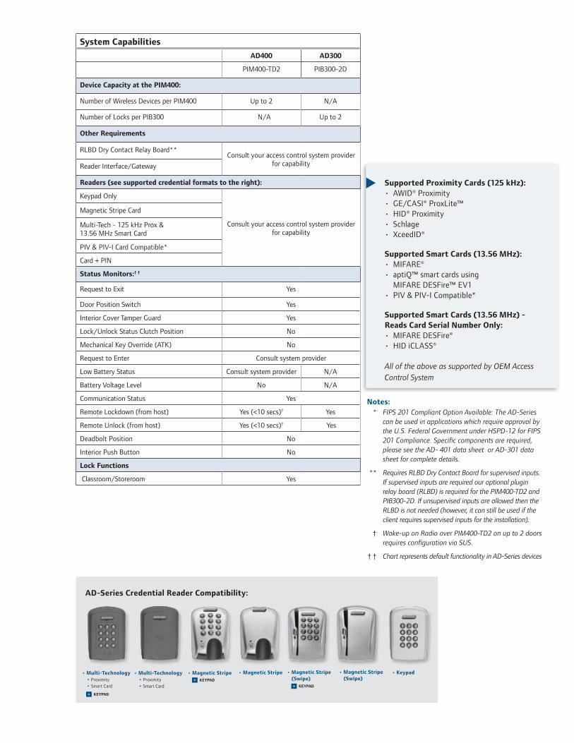
System Capabilities
AD400 AD300
PIM400-TD2 PIB300-2D
Device Capacity at the PIM400:
Number of Wireless Devices per PIM400 Up to 2 N/A
Number of Locks per PIB300 N/A Up to 2
Other Requirements
RLBD Dry Contact Relay Board** Consult your access control system provider
for capabilityReader Interface/Gateway
Readers (see supported credential formats to the right):
Keypad Only
Consult your access control system provider for capability
Magnetic Stripe Card
Multi-Tech - 125 kHz Prox & 13.56 MHz Smart Card
PIV & PIV-I Card Compatible*
Card + PIN
Status Monitors:† †
Request to Exit Yes
Door Position Switch Yes
Interior Cover Tamper Guard Yes
Lock/Unlock Status Clutch Position No
Mechanical Key Override (ATK) No
Request to Enter Consult system provider
Low Battery Status Consult system provider N/A
Battery Voltage Level No N/A
Communication Status Yes
Remote Lockdown (from host) Yes (<10 secs)† Yes
Remote Unlock (from host) Yes (<10 secs)† Yes
Deadbolt Position No
Interior Push Button No
Lock Functions
Classroom/Storeroom Yes
Notes: * FIPS 201 Compliant Option Available: The AD-Series
can be used in applications which require approval by the U.S. Federal Government under HSPD-12 for FIPS 201 Compliance. Specific components are required, please see the AD- 401 data sheet or AD-301 data sheet for complete details.
** Requires RLBD Dry Contact Board for supervised inputs.
If supervised inputs are required our optional plugin relay board (RLBD) is required for the PIM400-TD2 and PIB300-2D. If unsupervised inputs are allowed then the RLBD is not needed (however, it can still be used if the client requires supervised inputs for the installation).
† Wake-up on Radio over PIM400-TD2 on up to 2 doors
requires configuration via SUS.
† † Chart represents default functionality in AD-Series devices
Supported Proximity Cards (125 kHz):• AWID® Proximity• GE/CASI® ProxLite™• HID® Proximity• Schlage • XceedID®
Supported Smart Cards (13.56 MHz):• MIFARE® • aptiQ™ smart cards using
MIFARE DESFire™ EV1• PIV & PIV-I Compatible*
Supported Smart Cards (13.56 MHz) - Reads Card Serial Number Only:• MIFARE DESFire®• HID iCLASS®
All of the above as supported by OEM Access Control System
AD-Series Credential Reader Compatibility:
• Magnetic Stripe
• Keypad• Magnetic Stripe (Swipe)
• Magnetic StripeKEYPAD+
• Magnetic Stripe (Swipe)
KEYPAD+
• Multi-Technology • Proximity • Smart Card
• Multi-Technology • Proximity • Smart Card
KEYPAD+

877-671-7011 • securitytechnologies.ingersollrand.com ©2012 Ingersoll Rand 000076 11/12
INGERSOLL RAND, the Ingersoll Rand logo, SCHLAGE, the SCHLAGE logo, XceedID, Von Duprin, Falcon and aptiQ are trademarks of Ingersoll Rand plc, its subsidiaries and/or affiliates in the United States and other countries. GE, CASI and ProxLite are trademarks of General Electric Corporation. MIFARE and MIFARE DESFire EV1 are trademarks of NXP B.V. HID and iCLASS are trademarks of HID Corporation. AWID is a trademark of Applied Wireless Identifications Group. Corbin Russwin is a trademark of Corbin Russwin, Inc. Sargent is a trademark of Sargent Manufacturing Company. Yale is a trademark of Yale Security, Inc. Best is a trademark of Stanley Black & Decker. Dorma is a trademark of DORMA Door Controls, Inc. All other trademarks are the property of their respective owners.
Cylinder CompatibilityFull Size
(key-in-lever 6 pin)Full Size
(key-in-lever 7 pin)FSIC
(6 & 7 pin)SFIC
(6 & 7 pin)
Schlage
Falcon®
Sargent® (10L + 11L Full Size)
Corbin Russwin®
Yale® (includes Medeco 31*0100 FSIC)
Best®
= with cylinder or less cylinder options = less cylinder only
= less cylinder, only with Sparta and Rhodes levers Note: See pricebook for specific configurations.
AD-Series Electronic Locks from Schlage are built from the ground up to provide more options, more functionality and more compatibility than any other solution on the market today. Designed to suite with the most popular lever styles and finishes, Schlage AD-Series can be configured to accept most major key systems.
Configure Your Lock:We have created a web-based product selector tool that can help you configure your AD-Series lock to meet your needs. To check out the tool, please visit www.schlage.com.
Lever styles
Sparta Rhodes
Athens Tubular
Warm tone finishes
605 606 612 643eBright Brass Satin Brass Satin Bronze Aged Bronze
619 625 626 626AMSatin Nickel Bright Satin Chrome Satin Chrome Chrome with Antimicrobial
Standard cylinders shown, SFIC and FSIC also available.
Mortise Lock (AD-300/400-MS)
Cylindrical Lock(AD-300/400-CY)
Exit Device Trim (AD-300/400-993)The AD-300 and AD-400 exit trims are exclusivelycompatible with exit devices made by Ingersoll Randwhen using the low current request to exit switch(RX-LC part # 050281 for Von Duprin 98/99 and Von Duprin 22/22F Rim/SVR devices and part # 650359 for Falcon 25 Rim devices)
Cool tone finishes


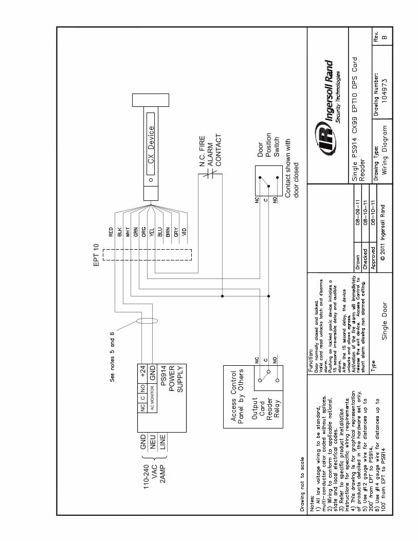


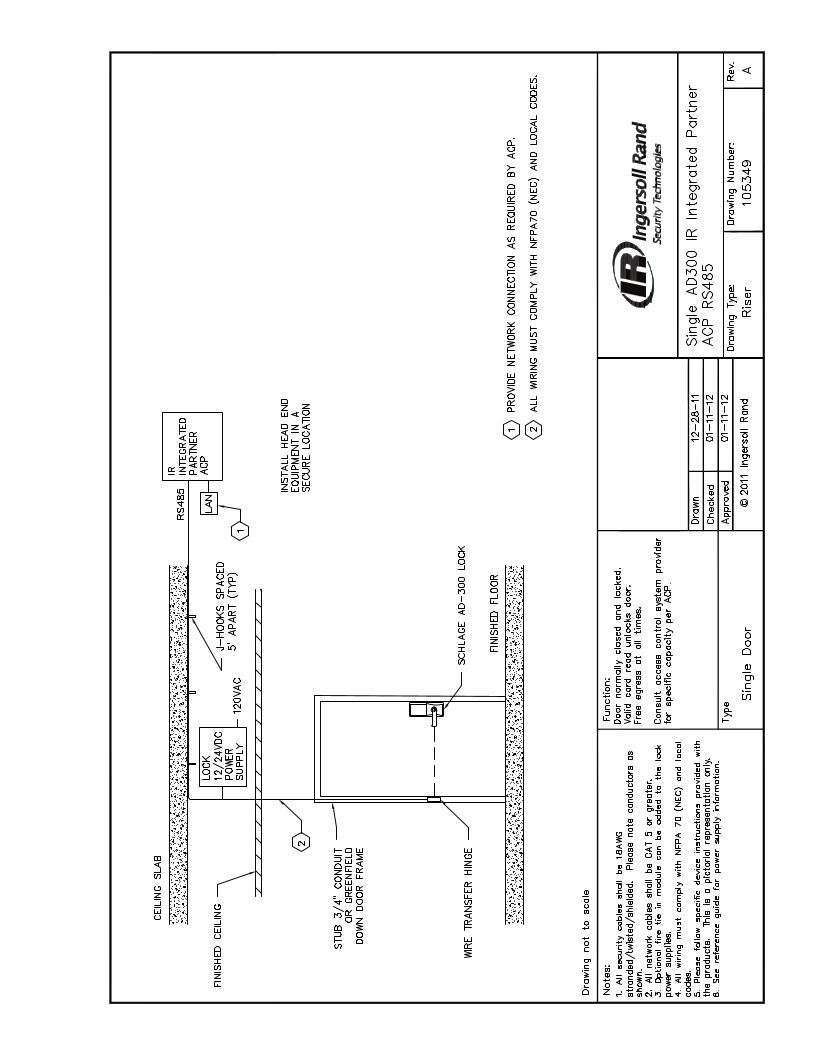


Ingersoll Rand (NYSE:IR) advances the quality of life by creating and sustaining safe, comfortable and efficient
environments. Our people and our family of brands—including Club Car®, Ingersoll Rand®, Schlage®, Thermo King® and
Trane®—work together to enhance the quality and comfort of air in homes and buildings; transport and protect food
and perishables; secure homes and commercial properties; and increase industrial productivity and efficiency. Ingersoll
Rand Security Technologies’ market-leading products include electronic and biometric access control systems; time-and-
attendance and personnel scheduling systems; mechanical locks; portable security; door closers, exit devices, architectural
hardware, and steel doors and frames; and other technologies and services for global security markets. Ingersoll Rand is a
$14 billion global business committed to a world of sustainable progress and enduring results.
securitytechnologies.ingersollrand.com ingersollrand.com
We are committed to using environmentally conscious print practices. ©2013 Ingersoll Rand 005390 01/13