
IR 017 272 AUTHOR Crannell, Philip A. TITLE … 385 250 IR 017 272 AUTHOR Crannell, Philip A. TITLE...
87
DOCUMENT RESUME ED 385 250 IR 017 272 AUTHOR Crannell, Philip A. TITLE Multimedia Centers: Concepts for the Future. INSTITUTION Gee & Jenson Engineer-ArChitects-Planners, Inc. West Palm Beach, FL. PUB DATE 10 May 95 NOTE 89p.; Paper presented at the Florida Library Association Annual Conference and Exhibition (72nd, Fort Lauderdale, FL, May 9-12, 1995). Color figures may not reproduce well. PUB TYPE Guides Non-Classroom Use (055) EDRS PRICE MF01/PC04 Plus Postage. DESCRIPTORS Access to Information; Facility Improvement; Futures (of Society); Information Technology; Library Equipment; *Library Facilities; *Library Planning; Library Services; *Multimedia Materials; *Telecommunications IDENTIFIERS Electrical Wiring; *Multimedia Technology; Raceways Distribution System; Structured Cabling System ABSTRACT Because of public demand for access to new media, librarians must be able to provide specialized systems and facilities. To support librarians in the planning and rethinking of new multimedia libraries, the firm of Gee & Jenson, which specializes in library design, created this guide. It provides an illustration of the possibilities and important issues to ensure multimedia service and flexibility. The topics discussed in section one include information equity; the virtual library; multimedia equipment; training; and library multimedia centers and functions. Section 2, "Critical Multimedia," covers support requirements such as power sources, communications systems, the data grid and hubs, and the telecommunications room. The third section, "Checklist and Worksheets," contains various aids designed to help organize the renovation and design process for multimedia facilities. Included in section 4, "Checklist," are: the steps needed for wiring a library for multimedia, lists important data access points in the library, and recommendations for information kiosks. "Cables and Raceways Design for Multimedia Libraries," section 5, is provided to assist librarians in planning for communications needs, and to assist a consultant in planning and designing a Structured Cabling System combined with a Raceways Distribution System (telecommunications and power grids). A glossary of related vocabulary is appended, and several figures and tables illustrate concepts. (MAS) *w********************************************************************* * Reproductions supplied by EDRS are the best that can be made * * from the original document. * ***********************************************************************
Transcript of IR 017 272 AUTHOR Crannell, Philip A. TITLE … 385 250 IR 017 272 AUTHOR Crannell, Philip A. TITLE...

DOCUMENT RESUME
ED 385 250 IR 017 272
AUTHOR Crannell, Philip A.TITLE Multimedia Centers: Concepts for the Future.INSTITUTION Gee & Jenson Engineer-ArChitects-Planners, Inc. West
Palm Beach, FL.PUB DATE 10 May 95NOTE 89p.; Paper presented at the Florida Library
Association Annual Conference and Exhibition (72nd,Fort Lauderdale, FL, May 9-12, 1995). Color figuresmay not reproduce well.
PUB TYPE Guides Non-Classroom Use (055)
EDRS PRICE MF01/PC04 Plus Postage.DESCRIPTORS Access to Information; Facility Improvement; Futures
(of Society); Information Technology; LibraryEquipment; *Library Facilities; *Library Planning;Library Services; *Multimedia Materials;*Telecommunications
IDENTIFIERS Electrical Wiring; *Multimedia Technology; RacewaysDistribution System; Structured Cabling System
ABSTRACTBecause of public demand for access to new media,
librarians must be able to provide specialized systems andfacilities. To support librarians in the planning and rethinking ofnew multimedia libraries, the firm of Gee & Jenson, which specializesin library design, created this guide. It provides an illustration ofthe possibilities and important issues to ensure multimedia serviceand flexibility. The topics discussed in section one includeinformation equity; the virtual library; multimedia equipment;training; and library multimedia centers and functions. Section 2,"Critical Multimedia," covers support requirements such as powersources, communications systems, the data grid and hubs, and thetelecommunications room. The third section, "Checklist andWorksheets," contains various aids designed to help organize therenovation and design process for multimedia facilities. Included insection 4, "Checklist," are: the steps needed for wiring a libraryfor multimedia, lists important data access points in the library,and recommendations for information kiosks. "Cables and RacewaysDesign for Multimedia Libraries," section 5, is provided to assistlibrarians in planning for communications needs, and to assist aconsultant in planning and designing a Structured Cabling Systemcombined with a Raceways Distribution System (telecommunications andpower grids). A glossary of related vocabulary is appended, andseveral figures and tables illustrate concepts. (MAS)
*w********************************************************************** Reproductions supplied by EDRS are the best that can be made *
* from the original document. *
***********************************************************************
i
9
Flbrida
72nc. Annual Conference anc
0 The. document has bean rehroduced is(*coned from the person or organization
onpnatmg0 'Amor changas hays bean mods to Iowa.*
reprosluchon quality.
Point ot view or °potions slated in thus docu-
mint do not nacessanly roprosent official0011 poidion or policy.
"PERMISSION TO REPRODUCE THISMATERIAL HAS BEEN GRANTED BY
TO THE EDUCATIONAL RESOURCESINFORMATION CENTER (ERIC)."

MULTIMEDIA CENTERS:
CONCEPTS FOR THE FUTURE©
AS PRESENTED TO
THE
FLORIDA LIBRARY ASSOCIATION72ND ANNUAL CONFERENCE
& EXHIBITION 1995
MAY 10, 1995
BY:
PHILIP A. CRANNELL, AIAEXECUTIVE VICE PRESIDENT
Copyright © by Philip A. Crannell, MA
All rights reserved. No part of this book may be reproduced or transmitted in any form or by any means,
electronic or mechanical, including photocopying, recording, or by any information storage and retrieval system,
without prier written pernusison from the author. for information, contact Gee & Jenson CAP, Inc.
GEE & JENSON Engineers-Architects-Planners, Inc. Telephone (407) ( 43-3301
3

MULTIMEDIA CENTERS:CONCEPTS FOR THE FUTURE©
TABLE OF CONTENTS
IntroductionCommitment to Flexibility In Library Design 1
Information Equity 3
Library Facilities In Transition 3
1.0 The Virtual Library 4
1.1 Keeping Pace with Evolving Information Technology 4
1.2 Adapting Libraries For The Changes Ahead
1.3 Important New Features in a Multimedia Library 6
1.3.1 Equipment 6
1.3.2 Utilizations 6
1.3.3 Optimizing Multimedia Equipment and Its Utilization 6
1.4 New Spaces to Support Multimedia Operations 7
1.4.1 Training Center 7
1.4.2 Group Multimedia Production Room 7
1.4.3 Output Center 8
1.4.4 Multimedia Support Center 9
1.4.5 Multimedia Classification Room and Receiving Center 9
1.4.6 Archiving Center 10
1.5 Introducing New Multimedia Functions Into Libraries 10
1.6 Renovation Projects 11
1.7 New Construction 11
1.8 Flexibility Tools 12
GEE & JENSON Engineers-Architects-Planners, Inc. Telephone (407) 683-3301
4

1.8.1 Flexibility Enhancements 13
2.0 Critical Multimedia 14
2.1 Power Features 14
2.2 Communication Systems 14
2.3 The Importance of the Data Grid 15
2.3.1 Data Grid Hubs 16
2.3.2 Telecommunications Room 16
3.0 Checklist "id Work Sheets 23
3.1 Important New Multimedia Areas in New Libraries
3.2 How to Critique a Multimedia Design Proposal 23
3.2.1 Critiquing a New Design for a Media Center
3.2.2 Multimedia Operations to Look For 25
3.2.3 Critiquing Existing Facilities as a Candidate for a Media Center 25
4.0 Checklist 37
4.1 Steps to Take to Wire Your Library for Multimedia 37
4.1.1 Programming Phase 37
4.1.2 Design Phase 38
4.1.3 Project Closeout Phase 39
4.1.4 Telecommunications Room Features 41
4.2 Characteristics of a Properly Wired Library 42
4.3 Important Data Access Points in Library 42
4.4 Information Kiosks 43
5.0 Cables and Raceways Design for Multimedia Libraries 44
5.1 What Kind of Cable Should You Use? 45
GEE & JENSON EngineersArchitectsPlanners. Inc. Telephone (4071683 -3301
1
1
5.2 What are the Advantages of Using Fiber Optic Cables? 46
5.3 How Does Fiber Optic Cable Differ From Copper Cable? 46
5.4 What Is A Broadband System? 48
5.5 What Are The Advantages and Disadvantages of UsingBroadband/Coax Cables? 51
5.6 What Are the Deciding Factors to Use Fiber Optic Cables vs. UTP? 51
5.7 What is the Most Economical Way to Wire the In-BuildingBackbone Subsystem? 53
5.8 Where Should the Telecommunications Room Be Located in theFacility? 53
5.9 What Size Telecommunications Room Will I Need? 53
5.10 What are the Conditions that Affect Cable Location Selection? 55
5.11 What Causes Interference or Static Noise? 55
5.12 What Can I Do To Minimize Voice/Data Signals Distortion andFailure? 56
5.13 Why Install Category Five Communications System? 57
5.14 What is Structured Cabling System? 58
5.15 System Architecture 59
5.16 System Configuration 61
5.17 Face-Plate Configuration 62
5.18 Space Requirements 62
5.19 System Infrastructure 65
5.20 In-Floor Distribution System 66
5.20.1 Under-Floor Duct System 66
5.20.2 Recessed Floor Boxes 66
5.21 Overhead Distribution System 67
5.22 Surface Mounted Raceways 67
GEE & JENSON Engineers-ArchitectsPlanners, Inc. Telephone (407) 683-3301
6

5.23 The Do's and Don'ts of Cabling and Raceways 68
The Important of Conduit 70
Flexibility Enhancements - Data Grid Routing Recommendations 71
Related Vocabulary (Glossary) 72
GEE & JENSON Engineers-Architects-Planners, Inc. Telephone (407) 683-3301

INTRODUCTION --COMMITMENT TOFLEXIBILITY IN LIBRARY DESIGN
There is tremendous potential for the various ways you can plan and prepare your library for thefuture. Preparation made today will enable your library to accommodate the expanding technologyand set the stage for future renovation or new construction projects.
We at the firm of Gee & Jenson, specialize in library design. We are devoted to the advancement oflibraries. You will find that we have taken a genuine interest in providing services that are devotedto resolving inherit and potential problems related to library system designs that do not work. Wecan identify innovative planning solutions for your library related to your existing facility andrenovation and new construction projects. We have taken a vested interest in our client's needs,interviewed the staff in an attempt to derive vital information that uniquely describe their libraryrequirements. We recognize important contributions multimedia libraries deliver to the academicworld, the community and our nation. There also is no doubt, that libraries will play an increasinglymon important role over the next ten years.
The National Commitment
As an expression of our national commitment to an expanded role for libraries, we offer thefollowing quote
. . to insure access for all areas and economic classes .... For industry to wire everyclassroom, every hospital and every library in the U.S. by 2000."
Vice President Al Gore
We can safely assume that over the next ten years, the information explosion will continue at anunprecedented pace. This explosion of information will be concentrated in formats that are onlynow being developed from innovations in software and hardware technology. These innovationsoffer exciting potential for a variety of users. The high concentration of information contained insmaller formats will make our libraries true resource centers that contain extraordinary amounts ofinformation on almost every type and class of knowledge, field of study and human expression,including audio and visual experiences. Just think for a minute how extraordinary these changes ininformation access are going to be. Imagine also the dramatic change in resources you will be ableto offer patrons compared to even a few years ago. The librarian's skill will be called on in ways thatwill challenge and stimulate their imagination regarding new ways to serve their patrons.
GEE & JENSON EnglneersArchitectsPL. Iners, Inc.
-1-Telephone (407) 683-3301

We have a recent example of the momentum that is building to turn these advances into expressionswe can relate to and perhaps even be entertained by. For the first time in over 60 years, a majornew entertainment studio was created. The distinguished prorlucers, Katzenberg, Geffin andSpielberg, formed an extraordinary company. Their focus was to combine their amazingly-giftedtalents to produce movies, animation and musical programs. With this combination of talent it isno doubt there efforts will be tremendously successful. However, they also specifically plan toproduce something that will be truly ground-breaking for the entertainment field: InteractiveMedia. Never before has this kind of talent and financial resources been dedicated in such an earlystage, as it is now to the development of Interactive Media. Interactive Media has had explosivegrowth in children and young adult segments with video games. Beyond video games, there havebeen only a few basic titles in this media so far. When developments have occurred, they've beenprimarily concentrated in children's material and reference sources.
The potential of what is ahead for Interactive Media, with Spielberg's creative talent, is amazing andexplosive. Vast new experiences are ahead for this explosive industry. Certainly we can expect lotsof entertainment-based material. However, the real benefit will be creative and market drivenmomentum to expand the interactive media segment into a legitimate place with conventional mediasuch as books, movies, videos, and audio tapes.
Interactive media will be flexible and allow a variety of interactive options to a broad range of users.You will select whether to take a passive role or interactive one. The same interactive title can beentertaining or educational.
The public is demanding access to these new forms of media, specifically in the information servicesarea.
What the Public Wants*
75% Information and Educational Services61% Movies on Demand55% Travel Networks31% 500 Channels
Source Jan. 1994 MCI survey
GEE & JENSON Engineers-Architects-Planners, Inc. Telephone (407) 683-3301
9
Information Equity
Librarians must realize the challenges they will face in providing access to this huge resource. Thedemand for hands-on interaction on the part of the Librarians, because of their specialized expertiseand knowledge, will be necessary to provide direct assistance to patrons. This high allocation of timein service to patrons will be very important. The complexity of source format and its varying globallocations will (for the near term at least) demand the professional expertise only librarians andmultimedia libraries can provide. This explosion of new information is rampant and, unfortunatelyan increasing amount can be accessed only with skills andcomputer-based tools, unavailable to theaverage patron.
Access to this information will also be costly. More than ever, libraries will have the responsibilityto maintain information equity for the public. Information equity means equal access regardless ofability to pay or technical skills. Librarians will serve as professional facilitators to access this vastinformation. Their skills and intelligence will be essential to assist the public in the navigation ofsome very complex routes to the information they need. Less of their time will be spent in therepetitive drudge type activities that now misuse so much of their time. Facilitating access is veryimportant and librarians are going to be busy doing this job properly. To properly provide thisservice, librarians will need specialized systems and facilities that support this responsibility.
Library Facilities In Transition
Gee & Jenson are committed to doing everything possible, as engineers, architects and planners, tosupport Librarians in the planning and rethinking ofnew multimedia libraries. This process involvesconsideration of a variety of issues: from dealing withcurrent needs to preparing for future needs.Librarians play a pivotal part in this transition. They are challenged with serving their patrons' needs(which are still heavily based on conventional information medias and sources) and also, must havethe built-in flexibility to allow for the evolution of the new multimedia library that is moreinformation diverse. The library facility will need to contain numerous types of interfaces to thisdiverse information. It will also need to have its own internal information grid, a system of hubs andconnections that can allow the library to be dynamic as it serves a variety of patrons' requirements.Provision in the information grid for optional connection to fiber optics, coaxial or twisted pair cableswill be important. Other provisions for connections to evolving technology suchas dedicated FMand infrared band widths must be made as well.
GEE & JENSON EngineersArchitectsPlanners, Inc.
- 3 -
Telephone (407) 683-3301

1.0 THE VIRTUAL LIBRARY
The library we envision will be a Virtual Multimedia Library able to assume different characteristicsand resource priorities based on the needs of the patron, academic program, or community prioritiesit serves. Depending on the user some would see its resources as oriented to fine arts or classicliterature. Others still, would see its emphasis directed toward science, business, or internationalaffairs. How the library is valued by the patron would be a function of the ease and extent to whichthey could access information. This access would occur through the use of a new library tool, themultimedia workstation. This workstation provides a study area devoted to the patron's own areaof interest. Utilizing the station as a tracking system, the librarian could evaluate how on-sitecollections and outside sources are used by patrons (done in an unobtrusive manner, of course).From this evaluation, libraries could weed out those items that are of little demand but occupyvaluable shelf space. Popular collections and on-line sources, could be expanded and optimized. Theresult would be a better use of resources at a time when every dollar must count.
We'll also see output devices that would allow production of paper or electronic copies of anythingavailable from the library or its resources. Information could be personalized. Patrons could selectfonts, sizes, and page formats to suit their preferences.
1.1 Keeping Pace with Evolving Information Technology
In an effort to keep pace with evolving information technology, areas of the library can be designated
to allow for specialized devices that would enhance the patrons' interaction with library resources.In specially equipped rooms, individuals or groups could utilize high resolution and/or large screenprojection devices. These interactive devices could be used in an educational setting to support videoconferences or video seminars with practically any higher education facility, community group orlibrary.
In reviewing the evolution of technology applicable to libraries, we must also envision thedevelopment of another form of information technology interaction simulators. Simulators arethe next logical device for interacting with information. Simulators started out in the defenseindustry and were originally developed to enhance the quality of training, while reducing the timerequired to certify military pilots. This application proved to be highly effective. Through theapplication of simulators, provides a conservation of resources and an enormous amount of moneythat would otherwise be spent. A more important benefit is that pilots can use simulators toexperience situations that could not be replicated any other way. Simulators deliver enormousamounts of information in the form of visual, audio, and special feedback to the user. A totalimmersion in the data set is possible. In the case of pilots, it's not unusual to see full sweats andexhaustion occur at the end of a training session in a simulator. "But why," you ask, "do I need to
GEE & JENSON Engineers-ArchitectsPlanners, Inc.
-4- 1 1Telephone (407) 683-3301
provide for a sizrulator in my library?" Well, maybe you don't need one right now, but it's anevolving media that will be developed.
The founder of Blockbuster Video, Wayne Huizenga, has a prototype amusement park that includestwo simulators: a jet and a race car. These two items are the biggest attractions in the park. Thekids love them and thesesame kids will grow up with an appreciation for the simulator experience;an experience that will develop an expectancy for this level of media technology interaction.
The simulator makes sense for your future library. If you're still not sure, just consider what yourpredecessors probably thought when someone suggested that computer terminals would replace thecard catalog and videos, or that VCR's and computers would be available in the library. A proactivelibrary is one that is preparing for the future and also tracking the information and mediatechnology. Simulators, in some form, is to be considered when planning for the evolvinginformation technology.
1.2 Adapting Libraries For The Changes Ahead
Once we have an understanding of the potential for the future role of libraries, the next step is todetermine what can be done with the multimedia library facility. Librarians should consider whatnew physical features are needed and the expense associated with incorporating these features. Startby looking at where libraries are now from a physical prospective. Most would agree, thattechnologically, most libraries are average. You can find some PC's and dedicated data terminalsplu CD-ROM drives and a computerized card catalog. To install these systems, unless the librarywas less than 5-6 years old, was a process of compromising system needs with the limitations of thefacility. Equipment locations had to be selected based on where there was a power source or atelephone line and with a sight line to visually supervise its use. Installing these systems would havebeen easy if only there had been an empty chase or spare conduit. In past designs, there was no wayto anticipate the information revolution. No provisions were made for providing extra telephonelines or dean power. Planning for the future meant adding an extra telephone line and two or threeextra circuit breakers. Planning for the future now encompass a great deal more, especially withregards to renovation projects and new construction.
The multimedia library of the future is tasked with an enormous amount of responsibility. Theseresponsibilities cannot be avoided. Somehow, we must find a way for libraries to support anexpanded multimedia role.
GEE & JENSON Engineers-Architects-Rowers, Inc.
- 5 -
7.lephone 0071 683-3301

As an architect, I can't fully appreciate the professional and managerial adjustments that are goingto be necessary for librarians. I can, however, offer views on tools we can make available in the formof equipment and spaces in library renovatior s and nev. design programs that will help you withyour new responsibilities.
1.3 Important New Features in a Multimedia Library
To transition into a contemporary multimedia library means taking a fresh look at the functions thatoccur now and the changes necessary to adjust to the new multimedia role.
1.3.1 Equipment
We recognize that multimedia equipment has unique requirements to be properly utilized. It needsdedicated areas to function at its best. The equipment is expensive and needs some form ofsupervision. An ability to provide instructions on its use is also required. Another characteristic ismultimedia equipment always involves connections to other devices. CD-ROM towers, servers,printers, and networks are a few of the interconnections thatmust occur.
1.3.2 Utilizations
By the very nature of its use, multimedia equipment demands a focused involvement by the studentor patron. Exploiting the equipment's capabilities requires concentration and a fixed amount of timeto interact with it. Interface shells are varied in their protocols and users of one system will find itdifficult to use another configuration without training and practice.
1.3.3 Optimizing Multimedia Equipment and Its Utilization
There are always people who can function in the most hostile environments. They can tune outdistractions without affecting their performance. Some can also put aside awkward computerarrangements and peripheral locations. These types of people are the exception, however. What isimportant is to establish study and work environments that are conducive to efficiency. To properlycapitalize on the library's investment in equipment and deliver the highest potential for utilization,specialized areas and environments must be created within the library.
GEE & JENSON Engineers- Architects - Planners, Inc. 13-6-
Telephone (407) 683-3301

1.4 New Spaces to Support Multimedia Operations
The following areas are proposed to facilitate optimum performance for multimedia libraries andtheir students or patrons. Suggestions are also made regarding equipment and square footrequirements. Your actual library may find that combinations of these areas into one space or otherequipment configurations would work better for your needs. You and your architect will know best.
1.4.1 Training Center
Training is very important to advancing multimedia interaction. There are too many systems toexpect that the average patron will be able to sit down at a multimedia workstation and immediatelyfunction. Training at different levels is necessary to compensate for the variety of computerexperience patrons and students have. A facility capable of providing ongoing training oriented todifferent levels of multimedia literacy will increase the use of the library. An ideal location for thecenter is combining it with the community room of the public library. For an academic library adedicated facility may be appropriate. This training center could also be used as a multimediaviewing area or conventional classroom.
Basic equipment would include:
Video projection equipment capable -If direct connection to a computer and VCRData links to the telecommunications roomTen or more ports for multimedia workstations to tie into the library's data gridA satellite connection.
Size requirements for both facilities will be in excess of 400-600 SF.
1.4.2 Group Multimedia Production Room
The information imbedded within multimedia titles can be diverse. The format for its presentationcan be broad, ranging from a computer monitor to wall size screens. Also with multimedia, differentskills, some analytical, some creative can be orchestrated in the development of a multimediaproduct that would be impossible for many individuals to accomplish. Therefore, an area that allowsgroups to produce multimedia product is an asset for the multimedia library.
GEE & JENSON EngineersArchitectsPlanners, Inc. Telephone (407) 683-3301
.7_ 14

Accommodating this need in either the academic or public library is best accomplished with aseparate room. Equipment in the room would include:
Multimedia workstationsVideo projection equipmentAccess to the library data gridVCR
Sound amplifiersSound insulation materials
Typical area should be 150 to 200 SF. Multiple production rooms would be essential in academicfacilities.
1.4.3 Output Center
Another benefit of technology has been development of output devices that allow multimediaproducts to be converted into printed and electronically formatted material. The biggest advanceshave been in printers and plotters. Rich color on a variety of paper sizes are now possible atreasonable cost per page. The equipment, however, isexpensive. A full featured multimedia librarywill need to have an output center that allows users to produce hard copy or electronic versions ofmultimedia productions and sessions. Arrangements can be made to block output of material thatis copyrighted. Modest printing software is available to produce cost-accounting for hard copydevices. This allows the user to be charged for copies and helps minimize abuse of the output centerequipment and supplies. The following types of equipment would be located in the Output Center:
Color dye-sublimation printerColor ink jet printerFull-size ink jet or laser plotter, color capable
High-speed black and white laser printersColor copierBlack and white copierVCR
Sy Quest drivers
Digital tape drivers.
Area requirements - 250-300 SF.
GEE & JENSON Engineers-Architects-Planners, Inc. Telephone (407) 683-3301
-8-1.

1.4.4 Multimedia Support Center
Given the complexity of multimedia systems and their expense, specialized management of theseresources is important. A single location configured to coordinate the use of these systems ispreferred. Patrons can also arrange for use of specialized equipment and support at this center.Another location is needed for management of the output center. Usage can be monitored and feescollected where applicable. This facility could be configured in a separate room or as an island typecenter. Operations and roles would include:
Multimedia server managementTelecommunications resource managementData bank and CD-ROM tower managementOutput center controls and cost accountingSecurity functions.
Area requirements could be as small as 150 SF in an island configuration or 150-200 SF in a roomdedicated to this use.
This location will require specialized data grid access and a centralized location.
1.4.5 Multimedia Classification Room and Receiving Center
For some public libraries and most academic libraries another support function should beconsidered. Inclusion of a specialized multimedia receiving and classifications center will serve animportant role in the proper collection and categorizing of multimedia products when they arriveat the library. These products require special knowledge when receiving shipments, verifying theirintegrity and classifying them in a manner that ensures they are associated with the propermultimedia equipment and usage controls. Equipment within this operations would be:
Multimedia workstationVCR's
CD-ROM's
Audio decks.
Areas required for this operations will vary with the volume of material they process. A minimumwould be 150 SF.
GEE & JENSON Engineers-ArchltectsFlanners, Inc.
- 9 -
Telephone (407) 683-3301

1.4.6 Archiving Center
An archiving center is another multimedia function that deserves consideration. Such a center wouldbe essential for academic libraries and optional for public libraries. This facility would be availableto make electronic archive records of numerous types of electronic and hard copy data. New digitalarchiving technology allows capture of a spectrum of media from printed to video and storage onelectronic or very compact and stable tape formats.
Equipment would include:
Multimedia workstationsCD-ROM's
Color scanner (large bed)Black and white scanner (large bed)DAT drive
WORM driveVCR
Audio decks.
Area allocation - 250-300 SF.
1.5 Introducing New Multimedia Functions Into Libraries
The new possibilities for spacial relationships and functions are illustrated in the accompanyinggraphics. Actual layouts and equipment for a specific library may involve issues not considered inthis study. Also, juxtapositions relative to other library functions can be done in a manner sensitiveto the actual library program and budget.
There are, however, basic considerations for renovations and new construction projects. As thesenew functions are introduced into the library, we need to understand how the changes will effecteach project category.
GEE & JENSON EngineersArchitects-Plannors. Inc.
-10-
1 7
Telephone (407) 683-3301

1.6 Renovation Projects
Making changes to existing facilities to accommodate these new areas in renovation projects is themost difficult. Each renovation project will have unique characteristics to address; however, all havecommon issues that need to be understood before anything can be done:
What horizontal passageways are available and accessible?How accessible are these passageways to the telecommunications room or area?Are the locations where the multimedia equipment is going near the passageways?Is there an uninterruptible power source available?
After each concern is understood, a program to incorporate a data line or grid can be developed.Cost ti install these improvements will depend on the following:
Extent of barriers (beams, columns, floors, and walls) that have to be penetrated to route thegrid.
Relationship of the telecommunications room to the outside.Extent of access available to the passageways.Quality of the electrical system.Type of construction.
Actual cost will vary from building to building and there is no rule of thumb to estimate the cost ona per workstation basis. Another cost modifier is the type of facility the upgrades are to be installedin. The older the library the more expensive it is to adapt. This is especially true if you have a facilityclassified as "historical."
1.7 New Construction
Most librarians we talk to shudder at the thought of trying to incorporate provisions in newconstruction programs for the information revolution. They havea number of apprehensions thatcompound their ability to move ahead including the following:
Anxiety in selecting the best data system.Things are changing so fast I'll make a mistake.How do I know how to configure the system to be flexible?It will be too expensive.
Technology ambivalence.
GEE & JENSON Engineers-ArchitectsPlanners. Inc. Telephone (407) 683-3301

While we understand that immense changes in information technology are going to happen, a greatdeal of the apprehensions above are unfounded when logic is used. Most of the concerns areassociated with making a decision that could later become a bad one due to change. The mostsignificant design provision then that needs to be made is fcr change. Once that is solved most of theother concerns assume a lesser priority. How then should provisions for the new multimediafunctions and future change be incorporated into the new library?
1.8 Flexibility Tools
Try to do everything you can in the design stage to accommodate change that could be necessary ata later date. If your library design is set up for change, then you're flexible. Multimedia designs needflexibility more than any other trait. Flexibility is relative. How flexiblea facility will be is a functionof many different aspects of its design. Layout, building services, internal circulation characteristics
and structural elements play an important role in the facility's ability to accommodate change.
Fortunately there are certain elements that can be included in the design that will allow change tooccur later. Most involve careful selections of building systems and equipment that enhanceflexibility and provide for future change.
The following pages outline building systems and equipment that, if used in the facility, will greatlyincrease the flexibility of the facility to adapt to new systems and functions you want to include inthe future.
GEE & JENSON Engineers-Architects-Planners. Inc. Telephone (407) 683-3301
- 12 - Li

1.8.1 Flexibility Enhancements (General, Electrical, Structural, TelecommunicationsRoom)
(General)
Vertical Chases
Pitched RoofsSpare ConduitsAccessible CeilingsData Grid
Telecommunication Room on Exterior
(Electrical)
Oversized Load CenterSpare UPS Circuit
Surge Protection CircuitSpare ConduitPhone in Electrical Room
(Structural)
Steel Frame
Bar Joist or Open Truss Floor and Roof StructureAttic Space
Floating Floor Slab
(Telecommunications Room)
Oversized Equipment Mounting BoardRoom Size a Minimum of 50 Square FeetSpare Conduit to:o Roofo Exterioro High Use AreasAir-Conditioning
GEE & JENSON Engineers-Architects-Planners, Inc. Telephone (407) 6113-3301
-13-

2.0 CRITICAL MULTIMEDIA
Support Requirements
In preparing for change, our research indicates that there are support requirements that will applyto practically any of the advances in telecommunications and information technology. They are:
A clean power supply.An uninterruptible power source.
Regardless of the technology and no matter how complex the internal designs or functions of futuremultimedia systems, they will need power and a means of communication. It is not difficult orexpensive to include these provisions in libraries, as you'll see below.
2.1 Power Features
An effective power source can be included with very little increase in the electrical budget. At thevery least, the electrical system can have the capacity to add a system later. There is usually no extracost associated with this future add-on feature. The same is true for an uninterruptible power source.Overall extras may add 5% to 10% more to the electrical budget.
Spare Electrical Panel Capacity2-Level Power Surge Protection
UPS (Uninterruptible Power System)Clean Power
2.2 Communication Systems
A well-designed communications system will result in a properly wired library. Listed below area few of those characteristics:
Characteristics of a Properly Wired Library
Total Flexibility for New Information TechnologyEasy Access to Data GridEasy Access to Exterior
Centralized System ManagementHas a Variety of Community Room Information OptionsSupports a Range of User Skill Levels
GEE & JENSON Engineers-Architects-Planners, Inc.Telephone (407) 683.3301
- 14 - 2

It is relatively easy to provide tremendous communication clodbility in the wired library. Make sureyou can accommodate any communication conductors that could be used. To do this simply providea flexible data grid. There are lots of options to consider in making this choice. The choices rangefrom wired to wireless. Specifically they can be grouped as follows:
Data Distribution Types
WirelessFM
InfraredWiredTwisted PairCoaxial
Fiber Optics
For each of the systems there are characteristics and provisions to consider in order to properlyintegrate the data grid into the facility. These are basics that, when incorporated into your selectionprocess, will make the system easy to use in the future as well.
2.3 The Importance of the Data Grid
The glue that holds all this together is the data grid. The grid is the definition of informationflexibility. Everything that can happen will be a function of the grid design. A few relatedobservations:
Data Grid Facts
Its cheapIts easy to install during constructionIt never wears outYou never have enough
It's your insurance for the future
GEE & JENSON Engineers-Architects-Planners, Inc.
-15 2Telephone (407) 683-3301
2.3.1 Data Grid Hubs
Serving as the intersections and access points in the data grid are the hubs. Typical hub locations are:
Telecommunications RoomCirculation Desk
Reference/Information DeskStaff Work Room
Important Data Grid Access Pointe in LibraryLobbyChildren's AreaCommunity RoomStudy AreasReference Section
Catalog AreaPeriodicals AreaStaff Work Room
Librarian's Office
2.3.2 Telecommunications Room
Of all of the design features to incorporate into a new facility, one of the most important is thetelecommunications room. This is where the information funnels into and out of the library. It's likean electronic version of the circulation desk. No library will be able to properly function withoutone. Its features are detailed below:
Telecommunications Room Features
Oversized Equipment Mounting BoardRoom Size a Minimum of 50 Square FeetSpare Conduit to:
Roof
ExteriorHigh Use AreasMake It Air-Conditioned
GEE & JENSON Engineers-Architects-Planners. Inc.
-16-
23
Telephone (407) 683-3301
The impact in cost and area allowances you should make:
$1,000 does wondersSlight increase for furnishings
How much space does it require?2% increase in total library square footageMore room for a telecommunications centerA minimum of 50 square feet.
Summary
We hope you will benefit from our suggestions for "Multimedia Centers: Concepts for the Future."This overview is merely a illustration of the possibilities and important issues to ensure multimediaservice and flexibility. Actual aesthetic concepts have not been discussed. As library architects,believe this is best addressed on an individual project basis. Our topic is broad and we are certainthat some items may have been overlooked. We trust this material may serve as a guide for yourlibrary planning. We at Gee & Jenson look forward to assisting you in any way that we can, shouldrequire further information on any aspect of this material. We would love to hear if any of oursuggestions prove useful.
Good luck on your new multimedia plans!
GEE & JENSON Ervnneers-Archltecti-Planners, Inc.Telephone (407) 683-3301
-17 - 2 4

The Telecommunications Lag orLibraries'that are Telecommunications-Challenged
8113/0 with
CarpetAll=_
19% withNo. Carpet
68% withDataTelephoneLines
32% with.No Da-0TelephoneLines
Source: Winter...94, School Library7IVleclia Quality, Carol Truitt,Survey of 146 Libraries and Media Centers.
25 BEST COPY AVAILABLE

1. Multimedia Control Center2. Receiving and Classification Room3. Archiving Room4. Media Equipment Service Center
26

Al1.
1. Multimedia Control Center2. Output Center3. Multimedia Labs4. Telecommunications Room5. General Library Circulation Area
27

1. Multimedia Control Center 6. Telecommunications Room2. View Room and Training Center 7. Output Center3. Receiving and Classification Room 8. Multimedia Labs4. Archiving Room 9. Open Multimedia Workstations Area5. Media Equipment Service Center 10. General Library Circulation Area
20
0
1111
111
1110
Mill
W11
1111
1611
1111
11iii
itniti
lli'
W W
W W
11II
II1
IIII
III
IIII
III
HII
III
IIII
III
IIH
III
IIII
III
IIII
III
11II
II1
11II
I
IIII
II1
1II
HII
III
III
IIII
III
III
HII
I1
III
IIII
II1
1II
III
II1
III M
adE
;
IIII
UII
IIII
II-
..
III
III
AII
IH
UII
IIII
4101
11
0I
III
IIII
IIII
IIII
IIII
IIH
11
IIII
II
IIH
HN
011
HII
II
11
IIII
IIII
III
IIT
T-
I III
11
onII
HII
IIII
IIII
WI
ri.
III
IIt
,,C
.,.A
V
1111
11
.KJ I:
IIII
II IIII H
III
III
III
IIIII
III
Ifr
=4
I
III
I!
...1
!IBIS
ki
,!..
IN-=
:6
IA=
AN
L
il-.1
IVA
- =
ii:i
PII
CI- . .
_. 1
1 1f11
0IN
,...E
....
..44
t 6.I
;-
-...i
.11
1118
11
1ilE
:.4
rA
nPr
i.-7
411
mow
'PA
'.
fki
411.
11,
yow
,riir
o
1110
lia'."
'..q
:ow
ltm
1,2,
41/1
11.
....
...._
..f
flim
...Ii
iiiiii
iffi
liliii
iiiiii
iriii
illii
ill. W
in W
/W11
1111
iiiiii
imm
il. W
W1,
/WW
WW
HE
WN
* ,
war
emor
mi e
imm
is-
c
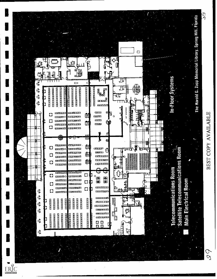
Tel
ecom
mun
icat
ions
Roo
m-
'Sat
ellit
e T
elec
omm
unic
atio
ns R
oom
IIM
ain
Ele
ctric
al R
oom
%P
In-F
loor
Sys
tem
s\
I
The
Har
old
G. Z
opp
Mem
oria
l Lib
rary
. Spr
ing
Hill
; Flo
rida.
BE
ST C
OPY
AV
AIL
AB
LE

3.0 CHECKLIST AND WORK SHEETS
The following section contains various aids designed to help organize the renovation and designprocess for multimedia facilities. We have included information that should help you in yourdiscussion with consultants, facility personnel and your peers. This material is not all inclusive, sodon't depend on the use of any one item as the only basis for a decision.
If you have any questions, we would like to hear from you.
3.1 Important New Multimedia Areas
in New Libraries
Telecommunications Room
Data and Power Grid
Multimedia Receiving and Classification Room
Multimedia Browsing Stations
Multimedia Production Suites
Multimedia Theater (Formerly a Programs Area or Discovery Center in a publiclibrary)
Multimedia Control Center
Multimedia Small Group Study Room
Archiving Center
3.2 How to Critique a Multimedia Design Proposal
3.2.1 Critiquing a New Design for a Media Center
Libraries are designed and construction documents prepared in a series of steps referred to as designsteps. Plans evolve in a series of stages that progressively add detail to the overall design beingdeveloped by the architect and his/her client. As a librarian, you don't need to be qualified toexamine the minute detail that goes into a complete set of construction documents, but you do need
GEE & JENSON Engineers-Architects-Planners. Inc. Telephone (407) 683-3301
-23- 3 1

to ask questions. As I have previously said, one of the most important factors that you can strive foris flexibility. Once you have a flexible design, functional, hardware, or system modifications can beaccommodated.
Be strong in your role as a client. You should be in charge of the process and the architect expectsit. The architect will respect your enthusiasm and respond positively.Sample questions to ask when critiquing a plan for a new design are:
What provisions have been made for a dedicated telecommunications room and how big isit?
Does the plan incorporate a data and power grid? If so, where is it and what type is it?Are there expansion circuits available in the power panels?Are there spare conduits and wire ways or chassis in all locations within the building?Is there a separate power circuit for surge protection specifically set up fortelecommunications and workstations?Is there a connection for future data terminals in the lobby?Is the community room set up for teleconferencing and access to the data grid?Is there sufficient room for at least a 50% expansion of equipment within thetelecommunications room?Does the structural system allow flexibility for future modifications?Can the HVAC system be adjusted to accommodate changes in usage?
GEE & JENSON EngineorsArchitectsPlanners. Inc. Telephone (407) 683-3301
-24-

3.2.2 Multimedia Operations to Look For
1. Does the plan have the following room spaces?
A telecommunications room dedicated for that useA community roomA multimedia production roomA multimedia viewing roomMultimedia capable small group meeting roomsMultimedia capable study carrelsA feature-rich lobby with kiosk
2. Are each of these rooms connected on a data grid and power grid?
3. Is there a reserve of at least 25% of the gross floor area available for dedicated multimediaoperations in the form of workstations or other devices allowing interaction with multimedia
devices or is there a space which can be converted with relative ease to provide for that samepercentage?
3.2.3 Critiquing Existing Facilities as a Candidate for a Media Center
A Work Sheet and Checklist
Introduction
Use of existing facilities to accommodate a media center is usually a function of economical, practical
or physical factors. In the renovation process you can seldom achieve the overall performance andflexibility opportunities possible in a custom designed facility. However, there are a number offacilities with many years of life remaining that may offer an option for additional space wheremoney isn't available for a new facility.
The material induded in this work sheet and checklist is structured to help identify the relative easeor complexity that will be associated with the renovation process for a specific building. The itemsare organized by groups of common elements within a building. Only physical items are part of this
work sheet and checklist. Other issues such as site constraints, regulation restrictions andneighborhood location can only be evaluated by you. It is an vbsolute requirement to have astructural engineer evaluate the capacity of floors in multi-story buildings to support design loadsfor a media center. If the capacity is below minimums, it is sometimes possible to augment thestructural systems without significant expense.
GEE & JENSON Engineers-Architects-Planners, Inc. Telephone (407) 683-3301
- 25 -
33

A scoring system ranks the relative degree of complexity the system found within the building willimpose on a renovation program. For the purposes of this process it is assumed that the actualelements found within the facility are in sound condition with sufficient serviceable life remainingfor a minimum of 10-15 years.
To start this process, familiarize yourself with the Work Sheet and Questionnaire first, then askappropriate questions of the individual most familiar with the facility. The best choices in order ofcontact would be:
1. Building owner or manager2. Building maintenance staff3. Repairman that services the specific elements in the building, such as A/C repairman,
electrician, etc.
If for some reason none of these contacts are available, an architect in your community wouldprobably be willing to take a hour or so and help you complete the Work Sheet and Questionnaire.
When you have discussed the building with one of the individuals above, then tour the facility to see
it for yourself and confirm the answers you received and resolve any unanswered questions youhave.
Structural Systems
The building's structural systems support materials that form the envelope separating interior spacesfrom the exterior and each other. What these systems consist of and how they are assembled isimportant to understand in a renovation program. Some structural assemblies are far moreaccommodating than others. Power and data grids will be introduced into the building, and theprimary barrier they face will be the building's structural system. In most cases the owners of thebuilding or maintenance technicians may be of assistance in identifying systems listed in thecategories below. If it is difficult to determine, a more detailed analysis can be obtained from theservices of an architect or professional structural engineer.
The following categories include the majority of building materials and/or assemblies of materialfound in facilities from 1920 to present. If you encounter a situation not covered by the work sheet,then check the one that appears closest. If you find multiple systems are in the same building, select
the system that appears to occupy the most area.
GEE & JENSON Engineers-Architects-Planners, Inc. Telephone (407) 683-3301
-26- 34

Structural Systems (Cont.)
Floor Types**
Select Point
Steel bar joint with concrete floor topping* (multi-story) 20
All concrete (monolithic system of floors, beams and columns) (multi- 16
Concrete slab on grade (always in a single-story application) 8
Precast concrete (prefabricated pieces of concrete elements manufactured 12
Timber or wood joist 0
Total Point Value
** Prior to decision to convert a facility to a media center, multi-floor structural floor systems mustbe analyzed to verify their ability to support new design loads.
Interior Wall SystemsSelect Point
0 Drywall over metal studs* 10
Drywall over wood studs 9
3 coat stucco over metal lath over wood framing 3
Partition style concrete block
Load bearing masonry or brick or clay tile 6
*Represents the optimum condition.
Total Value Recap
Total Point Value
Floor Type
Wall Type
Total Point Value
Point
GEE & JENSON EngineersArchitectsPlanners, Inc. Telephone (407) 683-3301
-27-3 d

BUILDING SYSTEMS
Telecommunications
Substandard telecommunications for a library is like trying to get to the moon with a compass; itrelies on inferior hardware and you will never get where you want to go. Unfortunately, thetelecommunication services for most buildings consist of a few beige boxes and maybe a punch down
strip for extensions. Most of the time this basic system is served by several 4 pair telephone lines that
have been pushed through a hole in the wall or ceiling. The better ones may have the wires in a 1/2"conduit. Saddest of all though, is this basic system is usually found on one wall in the janitor's closet
or utility room. Space is limited and little care is given to protection of its meager components.Fortunately, modifications to create adequate space for a telecommunications room is fairly easy.Review the conditions below to establish which one comes closet to those found in the existingfacility.
Select PointOne Value
A separate telephone room with room to double the size of the existing 15equipment. The room is located adjacent to an outside wall.*
Telephone equipment is located in janitor's or utility closet. 8
There is no isolated room for telephone equipment. The telephone panels 4are apparent or are scattered in various locations.
*Represents the optimum condition.
GEE & JENSON EngineersArchitectsPlanners, Inc.
- 28 36
Total Point Value
Telephone (407) 683-3301

BUILDING SYSTEMS (Cont.)
HVAC System
It would be the exception to find that the HVAC (heating, ventilating and air-conditioning) systemin an existing facility could easily be converted to support a new use as a library media center. Air-
conditioning, dehumidification, dust control and heating standards are far more complex in a mediacenter facilit7 than the typical library or other type of building. HVAC systems usually are difficultto modify and still get the correct performance when complete. Therefore, a system conversion isprobably going to be involved and complex.
Review of existing conditions are still important in order to estimate the degree or difficulty that will
be encountered in an upgrade program. Illustrated below are the basic system configurations to lookfor in the review:
Select PointOne Value
Centralized HVAC system with primary equipment located in a separate 15mechanical equipment room.*
Multiple HVAC units located in various places through the facility. 7
Separate heating systems and separate air-conditioning systems located 0throughout the facility. Each system has its own temperature control device.
Total Point Value
*Represents the optimum condition.
GEE & JENSON EngineersArchitectsPlanners, Inc. Telephone (407) 683-3301
- 29 - 30;

BUILDING SYSTEMS (Cont.)
Electrical Services
Electrical services within any building are always of concern w' a new use is proposed. In mostcases the original system will not be capable of supporting a new use without significant upgrades.New electrical and fire codes are always an issue. Unless the facility is less than five year; utd, expect
compliance problems.
The items listed below are structured to classify the relative ease or difficulty that will beencountered in an electrical upgrade. Since some issues associated with the evaluation will betechnical, most librarians will want to we the assistance of an electrician in completing theinspections of electrical systems prior to selecting their answers.
Select PointOne Value
The building's electrical entrance and distribution panels are in a single 20location with provisions for expansion. These panels are located in aseparate electrical room. Power from the electrical panels are routed to thevarious lighting, equipment and receptacle locations in conduits or otherdedicated cable ways.*
Electrical panels are mounted on an exterior wall (inside the building or 10outside). No separate electrical room is provided. There appears to be roomfor expansion.
Electrical panels are inside a room or space that also functions as another 3
use, such as HVAC, telephone or janitorial closet. No provisions forelectrical service expansion have been made and there doesn't appear to bespace available for new electrical panels.
The electrical system does not have its own room and shows signs of 0numerous modifications with portions of the original system appearing tostill be in use.
*Represents the optimum condition.
GEE & JENSON Engineers-ArchitectsPlanners, Inc.
-30-
3S
Total Point Value
Telephone (407) 683-3301

BUILDING SYSTEMS (Cont.)
Lighting Systems
The lighting requirements for a media center are specialized. Therefore, it would be nearlyimpossible to find a lighting system containing enough serviceable elements to allow an economical
conversion in a renovation program. As a resuli, no evaluation of the lighting system is going to BEa factor in the ease or complexity of a facility renovation. Existing lighting will be discarded except
for possibly in a service area. No points are assigned this area.
Total Point Value
Rest Rooms & Plumbing Systems
PointValue
Rest room sizing regulation and accessibility standards mandated by the ADA can be expected torequire extensive rest room modifications when a renovation program is implemented. Therefore,it is generally assumed that the rest rooms will go through a major modification no matter what theuse or the condition of the existing facilities were in. Therefore, rest room review should not playa very significant role in your evaluation. No points are assigned this area.
PointValue
Total Point Value 0
GEE & JENSON Englneers-ArchitectsPlanners, Inc. Telephone (407) 683-3301
- 31 -
3 !",)

BUILDING SYSTEMS (COnt.)
Roofing
A watertight roof is an obvious asset for any building. However, in a conversion program there areother aspects of the roof that make the process of upgrading the HVAC system and introducing adata and power grid either more difficult or easier. The key factor is accessibility to the spaceunderneath the roof. The easier it is to gain access to the roof and modify or install new systems, the
more economical the process will be. The ideal roof is a pitched roof with gable ends. After that, apitched roof with hips. The least desirable type is a flat roof. This is also the very type of roof thatleaks the most. The steeper the pitch, i.e., a 9-inch on 12-inch versus a 5-inch on 12-inch, the better.The descriptions below illustrate the various roof types you may encounter in a prospective facility.
Select PointOne YaLue
Pitched roof with open trusses and minimum of 5 on 12 pitch. Gable end 20condition.*
Pitched roof with open trusses and minimum of 5 on 12 pitch. Hipped at 15ends.
Single pitch roof (no ridge, it slopes in one direction only), minimum of 5 on 312 pitch.
Flat roof. ('
Total Point Value
*Represents the optimum condition, but the higher the pitch the better.
GEE & JENSON Engineers-ArchitectsPlanners, Inc.
- 32 -
Telephone (407) 683-3301

EXISTING FACILITY
SCORE SUMMARY
Recap the score from Work Sheet and total them in the approp:!ate space. Compare your total withthe point ranges assigned to each category of renovation coraulexity.
Building System Point Value
Structural Systems
Floors
Wails
Telecommunications
HVAC
Electrical
Lighting (No Points)
Rest Rooms & Plumbing (No Points)
Roofing
Total
Total Points
0
0
*
* See Renovation Categories on next page to rank your facility's ease or difficulty as a candidate forrenovation.
GEE & JENSON Engineers-ArchitectsPlanners, Inc. Telephone (407) 683-3301
33 41

RENOVATION CATEGORIES
A. A strong candidate for renovation. The facility contains systems whichwill reasonably accommodate changes necessary for a media center. Abelow-average renovation cost will be associated with the project.
B. An average candidate for renovation. Some systems are marginal and willeither require significant modifications or add to the complexity of theconversion process. This project will require an average to above-averagebudget.
C. A marginal to poor candidate for renovation. Multiple building systemswill either interfere with the renovation program or require significantmodification abandonment. This will probably be a very expensiverenovation program. Prior to any decision to go any further with a projectin this category, an architect mid be retained to conduct a furtherevaluation of the facility.
Score Range
85-100 pts.
50-84 pts.
7-49 pts.
GEE & JENSON EnglneersArchitectsPlanners, Inc. Telephone (407) 683-3301
- 34 -

DESIGN PHASE
Steps in the Design of a Library
Introduction
In the design of any facility architects prepare the drawings for the building following the phaseslisted below. Ezn phase is organized to collect information and develop solutions in a logicalmanner with the final product a set of drawings, referred to as Contract Documents, that the general
contractor can build from. Once you are familiar with these phases you will be more comfortablewith the design process and able to operate in a more effective role as a client.
1. Programming- This is the very first time that you meet with the architect to start planningthe library project. Information regarding the project budget, site, specific needs within thelibrary and all of the space requirements are discussed and listed in the program. Allrequirements for each room and piece of equipment in the library should be listed. Theprogramming phase should take no longer than two to four weeks if it is well organized.Remember, the ideas developed during the programming phase are used to start the actualdesigns that occur in the next phase, the Schematics Design.
2. Schematic Design - All the work and detail developed in the programming phase is usednow to prepare site and floor plans and elevations of the exterior appearance of the library.All the rooms and their relationships to each other are shown in this stage. A summary oftotal square footage the plan requires is provided along with an estimated cost ofconstruction.
While it is not usually done for other types of facilities, we highly recommend that provisions
for the data grid be illustrated on the plans in this stage.
3. Preliminary Design - Preliminary Design is one of the most important stages in thedevelopment of a complete design package. Preliminary Design is the stage of the designprocess in which architects and engineers transform schematic designs from basic sketchesinto drawings containg more detail. These drawings start to incorporate mechanical,electrical and structural systems into the plan. It is at this phase that detailed provisions forthe data grid must be finalized. The next phase is preparation of contract documents and alldecisions made in the preliminary design phase will be incorporated in the contractdocument package. The cost estimate is revised based on the latest information in thepreliminary designs.
GEE & JENSON Engineers-Architects-Planners, Inc. Telephone (407) 683-3301
- 35 -
43

4. Contract Documents - This is the phase that prepares drawings used to build the library.Details, schedules, and wall sections are developed during this phase. These are thedocuments used to bid the project and the ones the contractor uses to obtain the buildingpermit and then build the building. Once again a revised cost estimate is prepared to confirmthe project on budget.
5. Bidding & Negotiations - The completed contract documents are distributed to interestedgeneral contractors in order for them to prepare their bids. The architect administers thisprocess and answers any questions. When bids are submitted, negotiations are held with thelowest qualified bidder to reach a final construction contract amount. The next step is toobtain a building permit and start construction.
GEE & JENSON EngineersArchitectsPlanners. Inc. Telephone (407) 6833301
-36-
4 4

4.0 CHECKLIST
4.1 Steps to Take to Wire Your Library for Multimedia
Introduction
The items listed below are included to help in planning your library for the demands that theinformation revolution is causing. The design process is complex for any library. You will need anexperienced architect with a good library background. Your architect will have many other itemsto review with you. We have included those that are especially applicable to the uniquerequirements of advanced telecommunication systems. This list is not comprehensive but shouldstill help you plan and design a library that is ready for these exciting advances.
When using this information, please don't hesitate to call with any questions. We will be happy toassist you in any way we can.
4.1.1 Programming Phase
Accept the fact that communication technology and media format will be under constantchange.
O Prepare a written description of the data system and data grid (wired or non-wired types)you plan to use. Generally state your library's future system plans and expectations.
O Communicate to your architect the need for flexibility in your library's data grid and hubsthat operate with the grid.
Insist on meeting with the design team's electrical engineer to express yourtelecommunication system's requirements and expectations for grid flexibility. Don't believeanyone who says this will be expensive and you can't afford it. It's simply not true. Datagrids are not that expensive and you can't afford to be without one.
O Require a separate telecommunications room of at least 50 square feet and make sure it is air
conditioned. A telecommunications room should have lots of extra conduit to the exteriorand to internal hubs that serve the library.
O Have your architect arrange a joint meeting with representatives of your local telephonecompany and long distance carrier. This meeting will be useful to learn of the capabilitiesto provide interactive data communications services and to accommodate your library's long-
GEE & JENSON Engineers-Architects-Planners, Inc. Telephone (407) 683-3301
37 4 5-

range needs. Ask how they are prepared to react to new information technology and whatplans they have to provide backup services should their primary system fail.
Insist on spare junction boxes and wire ways in circulation and reference/information deskcabinetry.
Require your library program to include existing or future provisions for:
An output room to contain printers, video cassette recorders, audio recorders andprovision future devices. Include lots of clean power, spare conduit and airconditioning.
Teleconferencing facilities, primarily in your community room.
Provisions for patron interface terminals in your lobby and at your book drop.
Flexible collection space to accommodate displays for new media types that will need
to be accessible to patrons.
4.1.2 Design Phase
Require a 3/4 inch diameter by 8 foot long grounding rod be installed in thetelecommunications room.
Require that the provisions for the data grid be included and shown in the schematic designs.
This isn't normally the way it is done, but in a library it is especially important to understand
from the start of design how the floor plan will accommodate this grid.
In the Design Development Phase check with the architect and electrical engineer to review
the latest data grid consideration, telecommunications room space allocations and airconditioning solutions that have been incorporated into the design.
Make sure all your telecommunications equipment will fit in the room. While this may seem
odd to state, it needs to be pointed out that sometimes the electrical engineer will not fullyunderstand the physical requirements of telecommunication systems. When this happensinstallers have a difficult time making room for everything in the telecommunications room.The best thing to do is have the architect call a meeting with key equipment suppliers, thetelephone company and the electrical engineer to review the space requirements andallocations for the system you will use in the library.
GEE & JENSON Engineers-Architects-Planners, Inc. Telephone (407) 683-3301
-38- 46

O In the Contract Documents Phase review the final design of the telecommunications roomand data grid within the building. Especially understand how the grid bypasses physicalobstacles such as steel and concrete beams and columns, masonry walls and concrete floors.
Ask to be shown samples of the trunk system (conduit, floor ducts or cable trays) andjunction boxes that will be used in the data grid.
Require a separate schedule of telecommunications equipment/system that will be includedin the library. The schedule will list equipment type, power requirements, physical size,manufacturer and any special location (floor or wall) needs. This schedule must be includedin the contract documents.
Require that the electrical engineer prepare a functional diagram indicating the relationship
of telecommunication elements within the system. This diagram must be included in thecontract documents.
In the Contract Documents Phase insist that grid terminations be readily accessible andprotected from debris or accidental blockage or closure. Insure that each rid terminationhas a junction box.
Require the electrical engineer include surge protection equipment on the primary powerentrance. We recommend an even more conservative approach of requiring a second levelof surge protection for circuits that service the telecommunications system.If you are in an area where lightning is common, have a lightning protection system includedin the design. Please note this doesn't take the place of a surge protection system. It will help
protect other basic equipment and your library from severe lightning damage but will notprotect your telecommunications system.
O Include a separate surge protection system on your communications lines. This will protectsensitive circuits from dangerous voltage surges in the communi- cations lines.
4.1.3 Project Closeout Phase
Require that the responsibility for installation of your data system equipment, conductorsand other components rest with the general contractor. As a single individual responsiblefor the system, the general contractor will not be able to blame you or others should there bedifficulty on start-up.
Insist that the specifications require that project closeout is only possiblE after a successfuldocumentation of the data systems and grids performance has been demonstrated and
GEE & JENSON EngineersArchitectsPlanners, Inc. Telephone (407) 683-3301
- 39 -
4 'i

sustained for at least a week. This should be done with all telecommunication systemsoperational and all building systems (HVAC, fire alarms, security) functioning in normalcycles.
Require a letter from the general contractor certifying that all spare conduits have beencleaned and are free of debris.
Require labels to be placed on exposed parts of the telecommunications grid and on junction
boxes to identify their use and destination within the library.
Require As-Built Data Grid Plans be supplied by the general contractor.
Finally, inform your librarians and maintenance staff about the locations of the spare datagrid locations and remind everyone of their responsibility to protect its access points fromobstruction or damage.
GEE & JENSON Engineers-ArchitectsPlanners, Inc. Telephone (407) 683-3301
-40-
48

4.1.4 Telecommunications Room Features
Minimum 50 Square Feet
Air Conditioning
Fire Protection System
Well Lighted
Grounding Terminal
Spare Conduit
Telephone
Isolated Electrical Panel
Adjacent Outside Wall
GEE & JENSON Engineers-Architects-Planners, Inc. Telephone (407) 683-3301
- 41 -
4 )

4.2 Characteristics of a Properly Wired Library
Total Flexibility for New Information Technology
Easy Access to Data Grid
Easy Access to Exterior
Centralized System Management
Variety of Community Room Information Options
Supports Range of User Skill Levels
4.3 Important Data Access Points in Library
Lobby
Children's AreaCommunity RoomStudy AreasReference Section
Catalogue AreaPeriodicalsStaff Work Room
Librarian's Office
GEE & JENSON Engineers-Architects-Planners, Inc. Telephone (407) 683-3301
-42-
4.4 Information Kiosks*
Basic menu items and services available on a touch screen computer located in thelobby.
Basic Information
o Hours of Operationso Floor Plans
o Rest Room Locations
o Key Media Center Features
o Special Programs & Events
Resource information
o General Resource Categories Availableo On-line Services Available
o Electronic Data Baseso Archives & Special Collectionso Graphics Illustrating Resource Locations
Library Resource Policies
o Access Procedureso Assistance Available
Patron/Student Questionnaire & Suggestions
* System Hardware
o Touch Screen Monitoro 486/50 Mhzo 100 MB Driveo 8 Megs RAM
GEE & JENSON Engineers-Architects-Planners, Inc. Telephone (407) 683-3301
-43-
51

5.0 CABLES AND RACEWAYS DESIGN FORMULTIMEDIA LIBRARIES
We at Gee & Jenson understand the need for infrastructure and planning, and apply thisunderstanding to cabling and raceways for many diverse projects.
This portion, although slightly technical, is provided to assist you to plan your communicationsneeds for your up coming library and to assist your consultant to plan and design a StructuredCabling System combined with a Raceways Distribution System (telecommunications and powergrids) that will serve you for years to come.
A Structured Cabling System is a distribution system that arranges cabling and raceways in alogically coherent and economical fashion so that a wide variety of applications can be supportedand modified/expanded in the future without major expense.
Today's communications technology isn't just expanding, it is literally exploding. Just a few yearsago copper was the primary medium for cable communications. In the 1990's fiber optic cablesbroaden the horizon of communication daily, as data speeds increase inquantum leaps and message-carrying capabilities expand in complexity and volume.
To keep pace with the information highway and the vigorously expanding technology, we at Gee& Jenson have been asking ourselves questions that have yet to come from our clients.
GEE & JENSON Engineers - Architects- Planners. Inc. Telephone (407) 683-3301
44 -5

1
5.1 What Kind of Cable Should You Use?
Although this may change as copper cabling standards continue to evolve, Unshielded Twisted Pair(UTP) can be used for almcst any conceivable application except the very high data rates for which
fiber optic is needed, see Table "Evolution of UTP".
EVOLUTION OF UTP
Date Data Rate Application
1975 4 Khz voice/PBX
1977 2.5 Mpbs ARCnet
1985 4 Mbps Token Ring
1989 10 Mbps 10BASE-T
1991 16 Mbps 16Mbps Token Ring
1992 20 Mbps ARCnet+
1993 100 Mpbs TP-PMD
1995 155 Mpbs ATM (Projected)
Mid-range, mainframe, voice, Ethernet, Token Ring, Arcnet and most other communi-cation systems
are all capable of using UTP as a highly reliable transmission media.
UTP cabling is so popular you could almost call it the LAN's Ubiquitous Transmission Preference.It is rapidly eclipsing its coaxial (COAX) and shielded twisted pair (STP) rivals.
It is easy to work withFlexible
Low costSmall diameterLightweightSimple to connect and terminate
GEE & JENSON Engineers-Architects-Planners, Inc. Telephone (407) 683-3301
- 45- 53
5.2 What are the Advantages of Using Fiber Optic Cables?
The application of fiber optic cables in high performance communication circuits is growing because
of operational and economical advantages o ver copper circuit. The advantages are:
High BandwidthLighter Weight
Noise, Surge, and Electromagnetic Interference (EMI) ImmunitySecurity
5.3 How Does Fiber Optic Cable Differ From Copper Cable?
Generally, an optical fiber consists of a hair-thin strand or core of optically PURE GLASS surrounded
by another layer of less pure glass called the cladding.
The cladding provides the difference in refractive index that allows total internal reflection of lightthrough the core, which in turn carries the light signals.
An optical fiber is always described by both the core and its cladding (62.5/125), the first numberalways defines the core diameter (see Fig. 1).
Fiber Optic has three (3) basic performance types:
1. Single Mode Step Index
Characteristics:
Carry signals over long distance before requiring regeneration.Band width in Giga Hz.Relatively inexpensive in comparison with associated equipment.Electronic equipment at either end of Fiber Optic is expensive.
GEE & JENSON EngineersArchitectsPlanners, Inc.
- 46 - 54Telephone (407) 683-3301

44.

O2. Multimode Graded-Index Fiber
Characteristics:
Carry signals over shorter distance.Band width as high as 600 Mhz.
Electronic equipment at either end of Fiber Optic is LESS expensive than Single Mode
Step Index Fiber Optic.
3. Multimode Step-Index Fiber
Characteristics (See Fig 2)
Has very specific applications in the manufacturing and process industry as well asin the medical profession.
Band width from 10 to 30 MHZ.
High tensile strength and excellent resistance to static fatigueRelatively inexpensive.
All the three (3) types of Fiber Optic cables are available for PLENUM rated andRISER (non plenum rated) applications.
5.4 What Is A Broadband System?
The use of broadband CATV as a multi media communications conduit enabled Local Area Network
(LAN) data to be transmitted on a coaxial (COAX) medium with other services such as homenetworks, public services access, manufacturing automation, (see Fig. 3).
Broadband data communications systems compared to baseband systems, such as Ethernet or TokenRing provide a sophisticated and flexible backbone solution. The technology is based on Cable TVsignaling and is sometimes referred to as CATV for Community Antenna Television.
The broadband backbones treat video or data transmissions as if they were a TV channel. Hence, its
advantage as a data backbone is its ability to simultaneously carry multiple services on a singlecable. Each service, (see Fig. 3) is assigned a unique channel or frequency on the cable. Each
GEE & JENSON EngineereArchttectsPlenners, Inc. Telephone (407) 683-3301
-48- 56


Terminal
UTP
MEMData Modem
Printer
Telephone Bypass CATV BackboneBackbone RG6 orR59 Coax PC
rivs:==
OCR
Coaxial
J20Public Service Access
Police DeptFire DeptLibrary
Traffc Control
1!)LAN4000D
PC w/ LAN4000CLANcard
Home Networks- Remote Education- Teleoommuting- Computer Service.Access
PC
Ethernet Sub-networks
IBM PS/2 w/LAN4000MC Enterprise Exchange
Token Ring Sub-networksRouter
Galaxy Exchange
0Manufacturing
Automation
4/16 Mbps
EngineeringWorkstations
1:-EL:11
Campus Mainframe Terminal-To-Host
LAN4000H
CATV Headend
Data Remodulator
Translator
Television Modulator
Satellite Video
NetworkManagement
5Figure 3.

broadband data service receives a particular channel assignment based on increments of 6 mega Hz,(see Fig. 4). The available broadband cable system bandwidth is typically 0- 450 mega Hz. In thiscase, the total number of services that could be simultaneously would be 75.
The data transmitted on broadband cable system require one channel for forward directiontransmission and on channel for reverse direction transmission for data transmission.
5.5 What Are The Advantages and Disadvantages of UsingBroadband/Coax Cables?
Besides the benefit of allowing multiple services on a single cable, broadband signals can travelfather than baseband network. The standard baseband Ethernet can travel along a single cable for
a length of 500 meters. By using Ethernet-on-broadband modems, the maximum distance of Ethernet
can be stretched to 3.75 Km, which eliminates the need for remote satellite telecommunications room
in some applications.
5.6 What Are the Deciding Factors to Use Fiber Optic Cables vs. UTP?
Ultimately, the deciding factors between the use of Fiber Optic versus UTP In-Building BackboneSubsystem are:
CostDistanceSpeed
See Table "Network Media" for comparison between UTP, SIT, COAX and Fiber Optic.
II II
GEE & JENSON EnglneersArchnectsPlennors, Inc.
51 - "jTelephone (4071633 -3301

Data Channel 1
Data.Channel n
Broadcast Video
Security
Teleconferencing
Coaxial MediaBroadband-CATV Backbone
Figure 4.
BEST COPY muolABLE
60

1
I I
1
1
1
1
NETWORK MEDIA
Type of Media Cost Cost Speed TypicalApplication
Unshielded twistedpair
Least
Expensive
Short Fast Enough Ethernet
Shielded twisted pair Expensive Short Very Fast Token Ring
Coaxial cable Inexpensive Medium Very Fast Ethernet, ARCnet
Fiber optic MostExpensive
Very Long Fastest All
5.7 What is the Most Economical Way to Wire the In-BuildingBackbone Subsystem?
All UTP and Fiber Optic cables used in In-Building Backbone Subsystem are wired in a manner that
resembles a physical STAR, (see Fig. 5) with the appropriate VOICE or DATA Main DistributionFrame (MDF) located in the center or hub of the star.
The maximum allowable length for UTP In-Building Backbone cables is 800 m (2,624 ft.).
The maximum allowable length for Fiber Optic In-Building Backbone cable is 2000 m (6,560
ft.).
5.8 Where Should the Telecommunications Room Be Located in theFacility?
Always ensure the cable from each data jack is a home run cabled back to the hub patchpanel.Cable DOES NOT exceed 100 meters (300 ft.)in length. This length is supported under IEEE
802.3 and IEEE 802.5 on UTP.
5.9 What Size Telecommunications Room Will I Need?
A good rule of thumb is one telecommunications room can service up to 20,000 square feet
of floor space or a maximum of 200, 10 ft. by 10 ft. cubicles.
GEE & JENSON Engineers-ArchitectsPlanners, Inc. Telephone (407) 683-3301

Workstation
Ethernet-Token Ring-Terminal Server
Computer CenterMainframe
PrinterWiring Closet
File Sharing
FiberOpticBacbone
LaserPrinterDocumentStation
A Hub - The part of the network where the circuits are connected. In a
LAN the hub is the main core of a star wiring application such as in
ARCnet, StarLAN, Ethernet or Token Ring. Hubs can be assembled to be
centrally managed and have the ability to isolate nodes from disruption
and catastrophes.
Figure 5.
BEST COPY AVAILABLE
6;.3

If a floor has more square footage than this, multiple satellite closets on each floor should beset up, each connected to a central closet on the floor where the system is housed. All thecentral closets are then connected to the main communications closet via the systembackbone.Allow one square foot of closet floor space for every 250 square feet of usable floor space.
5.10 What are the Conditions that Affect Cable Location Selection?
The following are only a few of many special conditions that may affect cable and location selection:
Large sources of heatHVAC equipments and return air plenumMagnetic materials, such as pipes or structural members, close to large cables carrying aheavy current loadsCorrosive materialsFlame and radiation resistance
MoistureThermal conductivity of soil or other surrounding mediumDepth of buried cable.
5.11 What Causes Interference or Static Noise?
In general, any device or power line carrying current or generating a magnetic field with high speedtransmissions will cause interference -and induce noise. A list of noise sources is provided below:
Fluorescent lightsAC power linesArc welding equipmentElectrical motorsHeating and ventilation equipmentTime clocks and electronic door locks. .
GEE & JENSON EngineersArchitectsPlanners. Inc. Telephone (407) 683-3301
.55. 63

5.12 What Can I Do To Minimize Voice/Data Signals Distortion andFailure?
Even the best designed communications wiring systems can go haywire if not properly installed. It
is important to understand that certain external influences or improper installation techniques caneasily cause low voltage signals to distort. Some of these external influences are:
Routing of Cables
Run cables over corridorsUse straight runsRun parallel to building contours
Cable Support
Use mechanical means to support cables, such as cable tray and hangers
Group cables
Separation From Sources or Electromagnetic Interference (EMI)
Comply with the minimum separation from 480 V power sources as shown in Table"Minimum Separation Distances of UTP From Sources of EMI"
Grounding and Bonding
All applicable regulations for grounding and bonding as defined by codes should be
strictly adhered to.
Condition <2kVA 2-5kVA >5kVA
1. Unshielded power lines or electrical equipment in 5 in. 12 in. 24 in.proximity to open or nonmetal pathway. (127 mm) (305 mm) (610 mm)
2. Unshielded power lines or electrical equipment in 2.5 in. 6 in. 12 in.proximity to a grounded metal pathway. (64 mm) (152 mm) (305 mm)
3. Power lines enclosed in a grounded metal conduit 3 in. 6 in.(or equivalent shielding) in proximity to a groundedmetal pathway.
(76 mm) (152 mm)
Table. Minimum separation distances of UTP from sources of EMI.
GEE & JENSON Engineers-Architects-Planners, Inc.
6 4Telephone (407) 683-3301

5.13 Why Install Category Five Communications System?
The Electronic Industries Association (EIA) and the Telecommunications Industry Association (TIA)
have established Five cable categories as listed in Table " THE EIA/ TIA CATEGORY SYSTEM" of
those We recommend use of category Five for the following advantages:
Flexibility to support almost any application
Ability to handle speeds up to 100 MbpsFlexibility for all topology
Greater noise immunitySupport for greater distance.
The EIAMA Category System
Category One.
Intended for basic communications and power limited circuit cable. Thereare no performance criteria specified in EIA/TIA SP-2840 for EIA /TIA568.
Category Two Low performance UTP. Typical applications include voice and low speeddata. Not specified in SP-2840, 568 or TSB40.
Category Three Applies to UTP cables and associated connecting hardware withtransmissions characteristics up to 16Mhz. Typical application include 4Mbps Token Ring and 10 BASE-T.
Category Four Applies to UTP cables and associated connecting hardware withtransmissions characteristics up to 20 Mhz. Typical applications include16 Mbps Token Ring and low loss 10BASE-T.
Category Five Applies to UTP cables and associated connecting hardware withtransmission characteristics up to 100 Mhz. Typical applications include16 Mbps Token Ring Emergency Application TP-PMD and CDDI.
Category Five makes good economic sense too. A recent AT&T study indicates installed CategoryFive cable is only a 20 percent premium over Category Three cable. The cost of cables in anynetwork communication system is usually.much less than five percent of the total cost. See Table"Price Comparison of Installed UTP Cables."
GEE & JENSON EngineersArchitectsPlanners. Inc. 6557 -
Telephone (407) 683-3301

Price Comparison of Installed UTP Cables(150 Ft. Horizontal Runs)
Cable TypeEnd UserPrice
150 Ft.Lobe Price
InstallationLabor 1.2.5 Hr. ©$45.00/ hr
Total EndUser Price
PremiumOver Cat. 3
Cat. Three $0.07 /Ft $10.50 $56.25 $66.75 N/A
Cat. Four $0.11 / Ft $16.50 $56.25 $72.75 9%
Cat. Five $0.16/Ft $24.00 $56.25 $80.25 20%
Source: AT&T 1993
5.14 What is Structured Cabling System?
A structured cabling system is a distribution system that arranges cabling and raceways in a logically
coherent and economic fashion so that a wide variety of applications can be supported and
modified/expanded in the future without major capital expense.
The key elements are:
Planning ahead avoids future problems.Think twice and wire once.The conduit to the future is the electrical conduit.
Instead of creating a horrible cable mess in your ceiling by allowing your cabling system to grow
haphazardly as needs arise, a structured cabling system (SCS) can be designed today to handle your
needs well into the next decade. Although the initial cost may be higher, the long-term savings in
both your money and time of a structured cabling system design are well worth the effort.
Today, mos t wners of large buildings and campuses recognize the need for structured cabling
systems that handle a number of diverse communications systems and support equipment from
multiple vendors.
II
66GEE & JENSON Engineers-ArchitectsPlanners, Inc. Telephone (407) 6833301
- 58 -

What has made SCS necessary?
The growing popularity of the LAN. The flexibility of the LANs is a nightmare formanagement. Some surveys indicate that up to 10% of the users on a typical LAN will move
every month. In a non-structured wiring system, every move might require pulling newcabling, which would limit the network flexibility and add to its material cost, not to mention
the labor cost.
Labor rates are always rising. It is far too costly to send technicians out year after year (notto mention day after day) to pull new cabling. SCSs should be designed tc last five to tenyears without major rewiring.
Information is vital for every business in today's world and the cabling plant is thefoundation over which this information passed. We can no longer afford to have milliondollar pieces of equipment passing invaluable, mission-critical information over second rate
cabling systems.
A structured cabling system's design is defined by analyzing the following elements: (see Fig. 6)
System architectureSystem configurationFace-plate configurationSpace RequirementsSystem infrastructureSystem cabling.
5.15 System Architecture
Communications-system architectures are defined by:
Logical Topology
Logical topology describes the order and the paths by which information flows. It permits analysisof locations where information must be transferred and allows establishing transfer methods.
67GEE & JENSON Enginoers-ArchitectsPlanners. Inc. Telephone (407) 683-3301
- 59 -

NIB
Ma
all M
K W
IN M
S W
illSi
ll11
E1
SIN
Oa
IIII
IIII
all
Wor
ksta
tion
Sys
tem
Hor
izon
tal
IDF
Ris
er
Sys
tem
Sys
tem
Bac
kbon
eS
TA
TIO
NS
yste
mB
LOC
KR
ISE
RB
LOC
KJU
MP
ER
7
1'1
VO
ICE
VO
ICE
1-4
PA
IR_
_ _
MD
F S
yste
m
RIS
ER
BLO
CK
JUM
PE
R
PR
OT
EC
TO
R
DE
MA
RC
AT
ION
BLO
CK
CO
PP
ER
PB
X
Cam
pus
Bac
kbon
eS
yste
m TO
IDF
BLO
O. B
OR
EQ
UIP
ME
NT
25 P
AIR
CA
BLE
S
TO
TE
LEP
HO
NE
CO
MP
AN
Y
14 P
AIR
PA
TC
H C
OR
DS
- -
-F
IBE
RLA
NO
PT
ICE
LEC
TR
ON
ICP
AT
CH
: EQ
UIP
ME
NT
PA
NE
L
tf
DA
TA
CA
BLE
9999
FIB
ER
OP
TIC
PA
TC
HP
AN
EL
CO
AX
CA
BLE
FIB
ER
OP
T1C
CA
BLE
FIB
ER
OP
TIC
TR
AN
SC
EIV
ER
LAN
SE
RV
ER
TO
FIB
ER
OP
TIC
TR
AN
SC
EIV
ER
S
FIB
ER
OP
TIC
PA
TC
HC
OR
O
FIB
ER
OP
TIC
PA
TC
HC
OR
D
Fig
ure
6.
66B
EST
CO
PYA
VA
ILA
BL
E
69
1
Physical Topology
Physical topology is the way the network nodes and stations are connected. The four basic physical
topologies are STAR, RING, BUS, and POINT-TO-POINT.
The data-communications network architecture segments includes:
The Front-end: The segment of the system that extends from the workstation to thetelecommunications room.
The Backbone: The segment between the telecommunication room and computer center.
The Back-end: Interconnects major computer-system components, such as data center wiring
linking hosts and peripheral equipment.
5.16 System Configuration
Building a cabling system's configuration, the designer should:
Determine what type of services are needed and,Where they are to be located.
A voice, data, and video station requirements schedule will help accomplish this task. The
'Telecommunications Systems Configuration Schedule" indicates room number, room description,
quantity and type of each device, and the point of termination. A great consideration should begiven to future needs and system expansion.
GEE & JENSON Engnmers-Architects-Plenners, Inc. Telephone (407) 683-3301
61
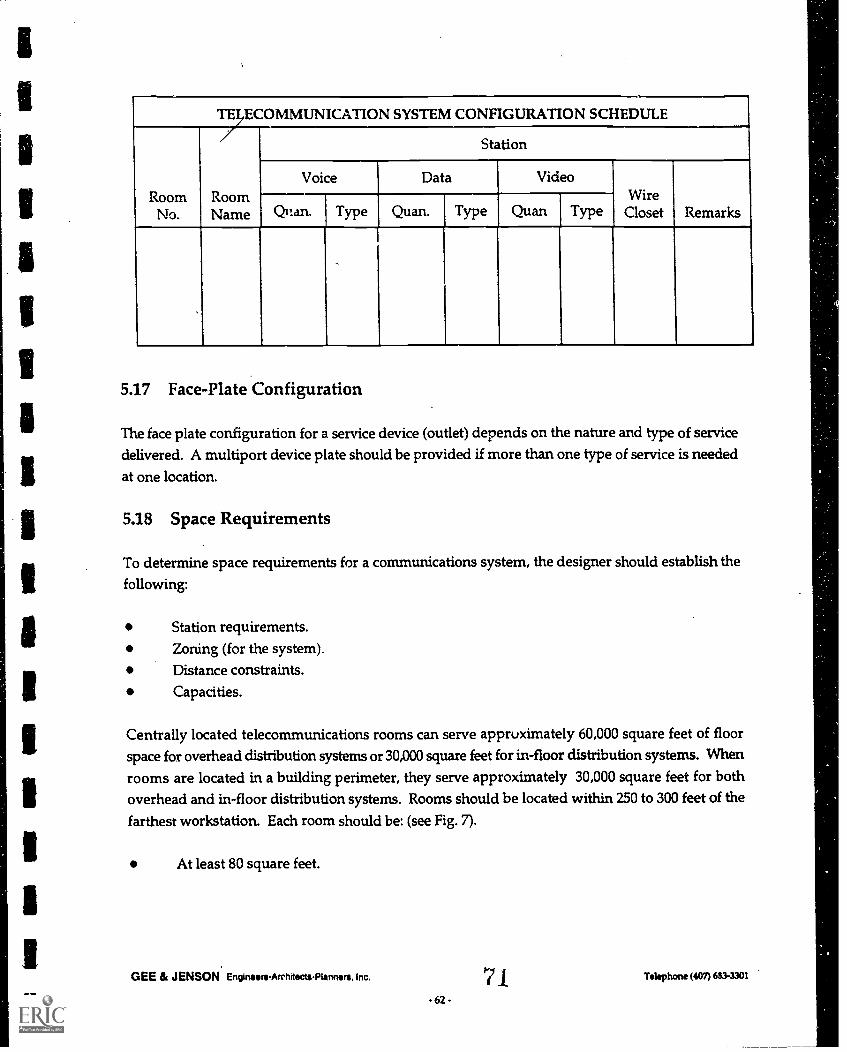
TELECOMMUNICATION SYSTEM CONFIGURATION SCHEDULE
RoomNo.
RoomName
Station
Voice Data VideoWire
Closet RemarksQttan Type Quan. Type Quan Type
5.17 Face-Plate Configuration
The face plate configuration for a service device (outlet) depends on the nature and type of servicedelivered. A multiport device plate should be provided if more than one type of service is needed
at one location.
5.18 Space Requirements
To determine space requirements for a communications system, the designer should establish thefollowing:
Station requirements.Zoning (for the system).Distance constraints.
Capacities.
Centrally located telecommunications rooms can serve appruximately 60,000 square feet of floorspace for overhead distribution systems or 30,000 square feet for in-floor distribution systems. When
rooms are located in a building perimeter, they serve approximately 30,000 square feet for bothoverhead and in-floor distribution systems. Rooms should be located within 250 to 300 feet of the
farthest workstation. Each room should be: (see Fig. 7).
At least 80 square feet.
GEE & JENSON EngineersArchitectsPlanners. Inc.
62 -
71_ Telephone (407) 6634301
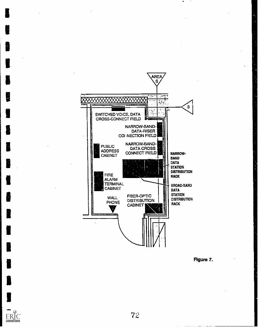
SWITCHED VOICE, DATACROSS-CONNECT FIELD
NARROW-BAND-DATA-RISER
COI NECTION FIELD
NARROW-BAND-DATA CROSS
CONNECT FIELD
IIPUBLICADDRESSCABINET
WALLPHONE
FIREALARMTERMINALCABINET
FIBER-OPTICDISTRIBUTIONCABINET
1--
72
NARROW-
BANDDATA
STATION
DISTRIBUTION
RACK
BROAD-BAND
DATA
STATION
DISTRIBUTION
RACK
Figure 7.

.
4" CON.DUIT TOSATELLITETELECOMMUNI-CATIONS ROOM
The Harold G. Zopp Memorial LibrarySpring Hill Florida
MODEM RACK4' RESERVED FOR
NETWORK #1
IN-FLOOR DUCT
4 RESERVED FORNETWORK-42
4' RESERVED FORNETWORK #3
4. RESERVED FOR'TELEPHONE LINES
IN-FLOOR
CLEAN POWER PLAN
UPS
SE9QRITY
ENCLOSURE FORLIGHTING CONTACTOR
AND H.O.A. SWITCH
TIME CLOCK
MECHANICALEQUIPMENT
PANEL
FACP -
COMPUTER TERMINAL
'COMPUTERSERVICE TABLE
P.A. SYSTEM BOARD
TV BOARD .
TLECOMMUNHCATIONS noom
=MEMO
POWER PANEL
TRANSFORMER
ELECTRICAL PANEL
LIGHTING
PANEL
nE4[..1 .Fcc)mr,ILINic-,AT IONS P.00SVI
POWER PANEL
LIGHTING PANEL
MAINDISTRIBUTION
-PANEL
r1:-.1r, I.. if(' tn. 1 r.
73 BEST COPY AVAILABLE
rt.

Walls should be lined with 3/4 inch fire treated plywood six inches above the floor.Doors should swing out.Environmentally controlled.At least one duplex power outlet on each wall.
5.19 System Infrastructure
The infrastructure to support a Structured Cabling Systems (SCS) includes overhead distributionsystem and in-floor distribution system (under floor distribution). Cable trays, wireways, andconduits can be used for overhead distribution systems. Under floor duct system, under floorcellular system, trench duct, and conduit can be used in in-floor distribution systems.
Today's buildings are changing every year. Becoming more automated, more complex in their needs.
Providing a distribution system for electrical power and telephone service is no longer enough,because tomorrow's buildings will need distribution channels for a sophisticated network ofelectronic systems, data processing and transmission, automated security systems, and energymanagement systems. Preparing a building for the Future making it an "intelligent" building.
The system infrastructure should:
Have capacity for the life of the building to handle ever increasing cabling requirement;Be flexible to adapt to building interior changes and increased number of work stations;Let your building meet its future needs without expensive modifications;Be able to accommodate all major communications and data systems connector devices.
GEE & JENSON Emmen-Architects-Planners. Inc.
.65.74Telephone (407) 683-301

5.20 In-Floor Distribution System
5.20.1 Under-Floor Duct System
3 Compartments - $15.00 per L.F.
DATA CompartmentPOWER CompartmentVOICE Compartment
Each service box will cost from $100 to $400 depending on the quantity and type of devices in thebox.
5.20.2 Recessed Floor Boxes
These boxes are available in:
Universal box which contains power, data, and voice devicesSingle box for each of the services (power,data, and voice) needed.
The above boxes utilize conduit distribution grid system.
Poke-Through Floor Box - $80.00 per box
Single box for each of the services needed.
Used primarily in multistory buildings where the floor box is fed from the floor below.
Raceway (conduit) System
This system is used primarily for low budget projects. It involves connecting strategic andimportant areas of the building to the main telecommunication and power rooms. See Table"Cost Per Linear Foot (installed)"
GEE & JENSON EngineersArchitectsPlanners. Inc. Telephone (407) 6833301..

TABLE: COST PER LINEAR FOOT (INSTALLED)
Conduit Size PVC IMC
3/4" $1.20 $1.50
1" $1.50 $1.80
2" $2.40 $2.60
4" $5.60 $7.80
5.21 Overhead Distribution System
Cable TraysWireways
Conduits
5.22 Surface Mounted Raceways
Used for above countersUsed in renovation projectsThree Compartment Raceway Steel: N \ A
Power Plastic: $3.25 /L.F.
DataVoice
Two Compartment Raceway Steel: $4.50/L.F.
Power Plastic: $1.50/L.F.
TelecommunicationsSingle Compartment Steel: $3.00 /L.F.
Plastic: $1.20 /L.F.
Multi-outlet System (Plug Mold) Steel: $1.50/L.F.
GEE & JENSON EngineersArchitects-Planners, Inc.
-67-76
Telephone (407) 683-3301

1
5.23 The Do's and Don'ts of Cabling and Raceways
DO - Buy the best UTP you can afford.
DO- Buy termination equipment (Rj45's, punch blocks, etc.) that meet or exceed the qualityof your cables.
DO - Label cable ends.
DO NOT - Mix up RJ45's designed to work with standard UP with those designed for solidUTP.
DO - Maintain the wire twist for all pairs up to the point of termination.
DO NOT - Share voice and data application in the same cable.
DO - Terminate voice and data cables into different punch blocks or racks.
DO - Use minimum bend radius of TEN times the cable diameter.
DO - Allow for sufficient cooling air flow in the telecommunications room.
DO - Put a lock on the wiring closet door and use it.
DO - On multi-floor installation, locate satellite telecommunications closets where there isa common vertical access (shaft).
DO - Install sufficient power outlets.
DO - Avoid routing cables near EMI noise sources, such as motors and AC power lines.
DO - Use the same cable throughout. Don't mix up cable from different manufacturers.
DO- Insist the installation be tested with equipment that meets or exceeds the requirements
for the installation, and get a certification report for each cable.
DO - Provide the telecommunications room with the following:
GEE & JENSON Engineers-Architects-Planners. Inc. Telephone (407) 683-3301
-68- 7 Pi,

Sufficient depth to accommodate data shelves or racks; minimum of 24 inches for acabinet with full width doors, or a depth of 48 inches for walk in cabinets.
Ground lug or ground bar with a minimum #6 AWG wire to an approved ground.Sufficient 110V AC power outlets for initial and future electronic equipments.Qutlets should be on dedicated circuits.
Sufficient HVAC air flow to prevent overheating of equipment in the Room.
Space for UPS or power conditioning equipment if required.
DO - Identify all potential sources of interference and route the cables away from them.Maintain a distance between the interference and the UTP of 10 times the diameter of amedium VOLTAGE AC power cable and 100 times the diameter of a high VOLTAGE AC
power cables.
DO - Whenever possible cabling should be installed over corridor areas or along lines thatare parallel to the contours of the buildings.
DO- Cabling installed above suspended ceilings should be supported either in a cable trayor cable hangers spaced 12 to 24 inches apart.
GEE & JENSON Engineers- Architects - Planners. Inc. Telephone (407) 683-3301
-69- 7

SUMMARY
CONDUITITS IMPORTANT PLACE IN THE WORLD*
It's cheap to purchase, it takes very little labor to install during construction. You '11 pay more
for it later, and labor to install it will be a killer.
It takes very little time to install during construction. You won't believe the disruption caused
when you have to install it once you have moved in.
Extra conduit is like money in the bank. It gives you comfort that it's there and it lets youpreserve all your options for later.
We never met a librarian who complained about having too much conduit. On the other handthere is long list of those who don't have enough and remain frustrated forever.
We all know blood vessels and arteries are the essential two-way circulation system of thebody which it cannot live without. Conduit serves the same essential function in a contemporary
library, it can't operate without it.
They say one can never be too rich or too thin. We say one can never have too much conduit.
(lo When in doubt about whether you need extra conduit between .areas of the library, don'tbelabor the decision, just have it installed.
In short, conduit is wonderful to have and miserable to be without. Plan your life accordingly.
* Conduit can also refer to floor duct systems and cable trays.
GEE & JENSON Engineers-Architects-Planners. Inc. Telephone (407) 683-3301

FLEXIBILITY ENHANCEMENTS DATA GRID
ROUTING RECOMMENDATIONS(Redundancy Is Important)
Hub Location Hub Connects to Space Below
Telecommunication Room Circulation Desk
Reference Desk
,. Exterior
Roof
" Staff Work Area
Librarian's Office
61 Community Room
,, Children's Area
,, Reading Area
Circulation Desk Staff Work Area
Library Office
., Reference Desk
" Children's Area
., Study Rooms
Community Room
,, Reading Area
Reference Desk Readin: Area
Staff Work Area
Community Room
., Library Office
" Children's Area
., Study Rooms
GEE & JENSON EnginowsArchhectsPlanners.
0
Telephone (407) 683-3301

RELATED VOCABULARY
1. Amphenol-type - 50 pin connectors (25 pairs) typically used in the past for telephone setconnections to central Pbx or phone company based switching. Some times referred to as
Telco-Type connectors or DB-50.
2. As-Built Plan - An As-Built Plan is the final drawing that indicates exactly where walls,structural systems, conduits and other critical items were installed once the building wasbuilt. These plans have very important information that reflects changes that were madeduring the construction process from the original design documents. Once in hand, theseshould be carefully guarded and made available to anyone doing renovation or service work
on the facility.
3. Asynchronous - A communications term that defines a data transmission mode in whichindividual bytes (characters) are transmitted, one byte at a time, along with individualstart/stop bits.
4. Attenuation - Deterioration of the strength of signals as they pass through a transmissionmedium (e.g., throug:a cables, outlets, connectors, patch panels, etc.)
5. Backbone- A term that refers to certain cabling segments used to provide connectivity overlong distances within buildings as well as between buildings in a campus. It also refer tocertain network architecture used to connect multiple subnetworks to one another.
6. Bandwidth - A measure of the carrying capacity of a communications device or medium,usually expressed in kilohertz (kHz) or megahertz (mHz).
7. Baseband- A term that refers to a band of frequencies and related equipment used to carrysignals in an unmedullated form (e.g., in their original electrical form, without modification).
8. Cable Tray - A long continuous rack usually located above a ceiling, that organizes andsupports loose wires or cables. Cable trays are expensive and used primarily in very largecomplexes. Cable trays usually start at a telephone or computer room and branch out. Cabletrays are the most expensive means of organizing and supporting large groups of wires orcables.
9. Ceiling Plenum System - This refers to the area between the ceiling and the underside of thestructure. For a ceiling plenum to be used effectively, it must allow easy access and theability for cables and wires to move in all directions simultaneously. The ceiling plenum can
GEE & JENSON EngineersArchitectsPlanners. Inc.
-72- 8 iTelephone (4071663 -3301

get cluttered and cumbersome to use later on but is one of the cheapest ways to provideuniversal distribution of data.
10. Chases - These are connecting spaces between floors and buildings, usually rectangular inshape, that allow passage between floors of wires, pipes, conduit and other building services.
While most chases are vertical, some can be hori-zontal in specialized situations. Chase sizes
can be as small as 6" x 12".
11. CMP - A designation established by the NFPA that refer to Plenum-Rated Cables.
12. Coaxial- A type of cable consisting of one central wire surrounded by a dielectric insulatorand encased in either wire or metal sheathing.
13. Coaxial Cable.- This is another type of data communication cable. It is identical in manyways to your home television cable. It has an exterior metal shield, a plastic core and a singleconductor in the center. Certain data systems require use of a coaxial cable.
14. Conduit - Usually a specialized plastic or metal pipe of varying size that can individuallycarry wires, cables or fiber optic bundles throughout a building. Conduits are cheap and canbe routed in any horizontal or vertical direction.
15. Cross Talk - The unwanted transfer of signals form one conductor another.
GEE & JENSON EngimentrchitectsPlanners, Inc.
-73-
8`) Telephone (407) 603-3301
16. Data Grid - This is a distribution system that connects the various hubs of the library witheach other and also provides data sources and interaction capabilities to individual locations.
The grid can be either under floor or overhead or may in some cases be a mixture of bothsystems. The grid material itself can be either conduit, floor duct or cable trays. Most datagrids use conduit. Basic elements of a data grid:
Junction Boxes - Located at each access point to the grid.Distribution System - The conduit, floor duct or cable trays that contain theconductors. All distribution systems have main.trunks, some have secondary trunks.Main Trunk - The primary element of the distribution system that connects hubs.Secondary Trunks - The branch elements of this system that connect the hubs toindividual users or terminals.Hubs - These are key distribution points in the grid. Hubs are connected to thetelecommunications room and to each other. They are usually located in a large in-
floor junction box that is easy to access.
17. Dedicated Power Source - This refers to individual circuits within the library's electricalsystem that are isolated from other power consuming equipment. Dedicated Power Sourcesare usually established for computers and their output systems in order to help ensure thatthis sensitive equipment will have its own power and will not be corrupted by fluctuations
in usage from other systems within the library.
18. Earth - British term for zero-reference.
19. Electrical Ground \Electrode - Cable or metal system that provides connection between theground wire of an electrical device to the earth for the purpose of establishing an electrical
ground.
20. EMF (Electro Magnetic Field) - An EMF condition is usually a negative impact that has the
potential to result in disruption and harm to magnetic media that contains numerical, videoor audio data. There are very few studies that provide concrete proof as to when an EMFcondition is excessive. The best advice is to avoid areas that could be a contributor. EMF'sare usually found adjacent to high-power overhead transmission lines or very largetransformers. Local utility authorities should always be contacted whenever there issuspicion regarding negative EMF conditions.
21. Encapsulating - A pourable, fast setting compound used to seal splice on cables.
GEE & JENSON Engintent-Architects-Planners. Inc. Telephone (407) 6113-330t
- 74 -

22. Ethernet- The local area network technology developed by Xerox, Intel and DEC in late 70's
to support 10 Mbps transmission speed.
23. Excess Loss - In fiber optic coupler, the optical loss from that portion of light that does not
emerge from the nominally operational parts of the device.
24. Extrinsic Loss - In a fiber interconnection, that portion of loss that is NOT intrinsic to thefiber, but is related to imperfect joining which may be caused by the connector of the device.
25. FDDI- An acronym that stands for Fiber Distribution Data Interference, an ANSI standard
for fiber based Token Ring physical and data link protocol.
26. FDM - An acronym that stands for Frequency Division Mu lti-plexing, a technique forcombining many signals on one circuit by separating them in frequency.
27. Fiber- Thin filament of glass or plastic comprised of a core and a cladding which is capable
of carrying information in the form of light.
28. Fiber Optics - This data conductor utilizes thin strands of glass fiber instead of metallicconductors. Fiber optic conductors are made of bundles containing hundreds of individualstrands. This is the most expensive system available for a data conductor. It offers theoptimum in data through-put and capacity. Attachment devices at each end of the, fiber optic
cable are also very expensive and should be priced as part of the total analysis.
29. Fire Stopping The use of special materials to prevent the outbreak of fire withintelecommunications spaces to block and prevent the spread of fire and smoke throughopenings in floors and walls.
30. Floor Duct - This is a variation of an under floor data grid system. A floor duct is arectangular opening placed slightly below the floor with a layout that is usually in a gridfashion and allows the installation and access of loose wires or cables.
31. Full Duplex - Is the opposite of a half duplex, the ability to communicate in both directionor send and receive over the same circuit.
32. Fusion Splicing - A permanent joint accomplished by the application of localized heatsufficient to fuse or melt the ends of two fibers to form a continuous signal fiber.
33. Gain - Increased signal power, usually the result of amplification.
GEE & JENSON EngineersArchttscts-Planners. Inc. Te **on: (407) 683-3301
-75-
84
34. Gas Pressurization - A method of preventing water from entering small cracks in cablesplices or sheath and or alerting personnel to larger leaks by keeping air core cables underpressure with dry gas.
35. Gauge - A term used to denote the physical size or diameter of a wire.
36. GIG - Prefix meaning billion.
37. Gigahertz A unit of frequency equal to one billion hertz.
38. Ground Conductor - A conductor in a ' ransmission cable or line that is grounded.
39. Ground Start - A signaling method where one station detects that a circuit is grounded at theother end.
40. Grounding Terminal Rod - A grounding terminal is an essential part of anytelecommunications and data system. It provides an important means of isolating theelectrical system from spurious electrical changes. The better the ground the higher qualityyour data will be.
41. Half Duplex - A telecommunications circuit that transmits or receives at one time.
42. Hard-Sheath Cable - Cable or wire contained within a continues inner or outer metallicsheath.
43, Hard-Wired - Wire and cable that is in place or installed for one designated purpose.
44. Hardening - Shielding and protecting of plant and equipment circuitry from the effects ofradiation and transient electromagnetic pulse (EMP) which accompany a nuclear explosion.
45. Harmonic Distortion - Interference resulting from some type of harmonic signal measuredin decibels (dB).
46. Harmonic Frequency - A frequency that appears as a result of a strong signal at a lowerfrequency.
47. Head-In - The main or top transmitting device in a Broadband network where alltransmissions are distributed.
GEE & JENSON Enginsers-Archltects-Planners. Inc. Telephono (407) 683-3301
76 -

48. Header Duct - The main or feeder duct for bringing cable from satellite/riser closets ordistribution ducts in cellular and under floor duct system.
49. Henry (H) - The standard unit of inductance. The inductance of a current is one HENRYwhen a current variation of one ampere per second induces one volt.
50. Hertz (Hz) - Standard unit of frequency, equal to one cycle per second.
51. Horizontal Wiring - The part of the wiring distribution system that extends station cablingfrom Intermediate Distribution Frame (IDF) to the workstation/telephone outlet.
52. Hybrid Cable - A cable used for communications which contains a minimum of two or more
conductors that carry electrical signals.
53. ICEA - Insulated Cable Engineers Association..
54. IEEE - Institute of Electrical and Electronic Engineers
55. IDC - Insulated Displa-ement Connection, The type of wire terminal that requires no wirestripping.
56. Impedance- The total opposition that a circuit offers to the flow of alternating current at aparticular frequency. It is a combination of resistance (R) and reactance (X) and is measured
in ohm.
57. Inductance- The property of a circuit that opposes any change in existing current during aperiod of a change.
58. Infrared Emitter - This term is usually associated with an assisted hearing infraredbroadcasting s: stem. An emitter is usually unobtrusive and can be mounted on a wall orceiling. Individual receiving devices pick up the radiated signal which is invisible to the eye.Emitters do not have to be in a line of sight for an infrared receiver to receive a clear signal.
However, emitters can be in conflict with other light sources primarily those from theoutside. Studies should always be done prior to making a commitment on an infraredsystem, especially where the library will have large windows that are open to direct sunlight.
59. Insulation - A material having good dielectric properties which is used to separate closeelectrical components, such as cables.
GEE & JENSON Engineers-Architects-Planners. Inc. Telephone (407) 683-3301
47.86

60. IDF An acronym that stands for Intermediate Distribution Frame. Also commonly referredto as a wiring closet or telephone closet.
61. I/O - Input/Output.
62. Junction Box - The junction box is an essential component of any data grid and provides a
beginning and end connector for conduit and under floor systems. Junction Boxes havecovers to protect the grid. Thus provide the best location to access the data grid.
63. Mounting Board - This is a fastening surface located in the telecommunications room usually
of plywood that allows the installation of various types of equipment and consoles relatedto telephone and telecommunications systems. A good mounting board is easily accessibleand is well lighted in order to facili-tate efficient and effective services. The larger themounting board and the more spare room it has available the better.
64. Multimode- Refers to a class of fiber optic cabling that is compatible with most applications
of fiber.
65. NEXT - An acronym that stands for NEAR-END CROSS TALK. It refers to crosstalkmeasurements between conductors media (pairs) in the near or transmitting end of signalling
equipment, as opposed to measurements taken between conductors (pairs) at the receivingend of a circuit.
66. RG-62- Designates a classification of coaxial cables, especially those are native to IBM 3270
connectivity scheme.
67. RJ - An acronym that stands for Registered Jack.
68. RJ-11 - Usually refers to an RJ type jack containing from two to six conductors.
69. RJ-45 - Usually refers to an RJ type jack containing eight conductors.
70. RJ-232- Refers to an EIA specification for asynchronous communications that feature a 25-pin connector.
71. Single Mode - Refers to a type of fiber optic cabling that contains a very narrow core strand,usually 8 to 10 micron in diameter.
GEE & JENSON Engineers-Architects-Planners. Inc.
- 78 -
8'i Telephone (407) 683-3301

72. Surge Protector - Surge Protectors are an essential part of any library's electrical system when
computers and sensitive electronic output devices, such as printers, are installed. SurgeProtectors stop an unexpected electrical pulse of power from an accidental shorting of theelectrical system from damaging the electrical components. They also protect from powergrid surges. Surge protection equipment is not very expensive and can be easily included inany renovation or expansion plan.
73. Telecommunications Room - This is a room no contemporary library can afford to bewithout. This room houses the equipment necessary to connect the library's communicationssystems (voice, data and video) to the outside world. It forms the key distribution point forthe data grid. Essential features are:
It must be large enough for technicians to service its equipment without beingcramped (minimum of 50 sq. ft.).
Be air conditioned and have extra unused conduit, floor ducts or cable tray space toallow for future installations of data systems.
74. Token Ring - A type of baseband LAN usually characterized by 4 or 16 Mbps transmissionspeeds.
75. Twisted Pair - This refers to telecommunications and data transmission conductors. It
generally is two- or four-pair wires that run between computers, output devices and othertelecommunication systems. Another common term for a twisted pair is a two or four wiretelephone line.
76. Under Floor System - This refers to a data grid that is located underneath the floor of a room.
The ins. illation can be in conduit or it can be in floor ducts. Under floor distribution systemsare considered the best data grids since they allow service to individual areas of the libraryin an unobtrusive manner.
77. UPS (Uninterruptible Power System) - An UPS is essential for telecommuni- cations,computing and data grid installations. This system is designed to provide clean power tosensitive electronic equipment. It also provides some temporary power during poweroutages that occur frequently in some parts of the country. If a total power outage occurs,an UPS may allow 10-15 minutes for sensitive computer equipment to be shut down andworking files or data stored before all power is lost. Uninterruptible Power Systems used tobe very expensive. Now they are practically priced and should be a common feature of anycontemporary library.
8bGEE & JENSON Engineers- Architects - Planners. Inc. Telephone (407) 683-3301
- 79 -

78. UTP - An acronym that stands for Unshielded Twisted Pair cabling.
79. Weatherhead or Gooseneck - This is a specialized section of conduit (usually metal) thatprojects out of a building and is curved like a gooses neck in order to prevent water and bad
weather from blowing into the conduit and then coming down into the building. This device
is usually found in older facilities where overhead services are connected from power ortelephone poles to the building. It occasionally provides a pathway for connections betweena satellite dish and the telecommunications room.
80. WECO-Style WECO is an acronym that s ands for Western Electric Company. WECO-Style
refers to modular or RJ-type UTP jacks which were originally designed by Western ElectricCompany.
81. 4-Mbps - A measure of speed meaning 4 million bits per second.
GEE & JENSON Enginee-eArchltectsPlenners. Inc.
- so -
8 9 Telephone (407) 683-3301


