IPicoâ„¢ Integrated Access Device - Niche Associates
28
User Guide IPico™ Integrated Access Device
Transcript of IPicoâ„¢ Integrated Access Device - Niche Associates

User Guide
IPico™ IntegratedAccess Device


Table of ContentsIntroduction ................................................................................................... 1
Technical Support ................................................................................................. 1Package Contents ................................................................................................. 2Required Accessories............................................................................................ 2
Quick Installation .......................................................................................... 3Network Topology......................................................................................... 4Placing Calls.................................................................................................. 5
Inter-site Telephony Connection ............................................................................ 5Setup .................................................................................................................................. 5Placing a Call ..................................................................................................................... 5
Remote PBX Connection....................................................................................... 6Setup .................................................................................................................................. 6Placing a Call ..................................................................................................................... 6
Remote PSTN (Public Switched Telephone Network) Connection......................... 7Setup .................................................................................................................................. 7Placing a Call ..................................................................................................................... 7
Remote PBX Extension ......................................................................................... 8Setup .................................................................................................................................. 8Placing a call ...................................................................................................................... 8
Configuration................................................................................................. 9Web Manager Configuration Tool .......................................................................... 9
Accessing the unit .............................................................................................................. 9Parameters......................................................................................................................... 9
LAN IP Address ............................................................................................................ 10LAN Network Mask ....................................................................................................... 10Master/Slave................................................................................................................. 10Quality of Service.......................................................................................................... 10
Outbound CIR ........................................................................................................... 10Data CIR.................................................................................................................... 10
Leading Digits (FXS Only) ............................................................................................ 11WAN.............................................................................................................................. 11
WAN Netmask........................................................................................................... 11Master IP Address..................................................................................................... 11Slave IP Address....................................................................................................... 12Default Gateway........................................................................................................ 12
Save.............................................................................................................................. 12Current Settings............................................................................................................ 13Defaults......................................................................................................................... 13
COMmander Configuration Tool ...........................................................................13Specifications.............................................................................................. 15
Indicators, Interfaces, and Controls ......................................................................15Product Capabilities..............................................................................................15Voice Support.......................................................................................................15Management Features .........................................................................................15Security Features .................................................................................................16Interfaces .............................................................................................................16Standards and Protocols Supported .....................................................................16
Troubleshooting.......................................................................................... 17Dialing and Placing Calls ......................................................................................17Using COMmander...............................................................................................18Using the Web Manager.......................................................................................18

Network Problems ................................................................................................19Quality of Service (QoS).......................................................................................19
Error Messages ........................................................................................... 20Appendix A .................................................................................................. 22
Version Number ...................................................................................................22Factory settings ....................................................................................................22Serial Parameters.................................................................................................22Passwords............................................................................................................22
LIMITTED WARRANTY................................................................................ 23

IPico™ Integrated Access Device User Guide
1
IntroductionCongratulations on your purchase of IPico™ WN400 Point-to-Point system. The IPico isa complete, all-in-one voice and data Integrated Access Device (IAD). IPico providesexcellent, cost-effective voice over IP (VoIP) and data integration for simultaneoustelephony and data transfer with Quality of Service (QoS) enforcement on a wide rangeof IP networks. The state-of-the-art IPico technology allows voice and data users to sharebandwidth on a single wide area network (WAN) link. Every telephone call iscompressed and assigned a dedicated voice channel, which is prioritized over the datachannel. Because IPico prioritizes voice over data, it guarantees toll-quality voicecommunications using advanced real-time protocols (RTPs). IPico’s patented QoSguarantees optimal use of multiple voice and data channels, regardless of bandwidthlimitations or network load.
IPico integrates fully with your existing IP data network and with your existingtelephones, facsimile machines, gateways, call managers, and local Private BranchExchange (PBX).
The IPico Model WN400-S supports voice, data, and fax communication within orbetween your sites. It can also be connected to an existing analog PBX. The IPicoWN400-O, in conjunction with the IPico WN400-S can be used to connect your site tothe Public Switched Telephone Network (PSTN).
These instructions will guide you through the setup and installation of IPico devices,enabling you to integrate the IPico devices into your network.
Technical Support• Contact our international support team by phone: +972-3-575-7488.
• Contact our U.S. support team by phone: (212) 686-7797.
• E-mail us at [email protected].
You can also fill out our support form at www.lucidvoice.com/support.htm (Lucid Voicekeeps all information confidential and does not sell or distribute mailing lists, customerlists, or information obtained from this form).

User Guide IPico™ WN 400 Integrated Access Device
2
Package Contents1. IPico unit2. Power supply3. Power supply bracket4. Power cord
Figure 1
Required AccessoriesYou will need:
• Two IPico units• Two power supplies• Two power supply brackets• Two (or more) analog (dual-tone multifrequency [DTMF]) telephone units (not
supplied)• Two Category 5 Ethernet (RJ-45) cables and an Ethernet hub (not supplied)
or• Crossover cable (not supplied)• Serial cable (optional)

IPico™ WN 400 Integrated Access Device User Guide
3
Figure 2
Quick Installation1. Pull power supply bracket until reaching ‘NC2’ mark.
2. Attach the power supply to the power supply bracket by firmly inserting the metallatches into the appropriate slots in the power supply bracket.
3. Place the IPico unit onto the power supply bracket, positioning the rear panelsideways from the power supply cable.
4. Connect the power supply cable to the power connection on the rear panel of theIPico and tighten the bolt.
5. Connect the power supply unit to the power connector.
6. Turn power supply switch to ‘ON’.
7. Turn on the IPico unit by pushing the ON/OFF button on the back panel. Youwill hear a beep. A green LED on the front panel indicates that the power is ON.
8. Connect each IPico’s WAN interface to a hub, using an Ethernet cable. (You mayalso choose to connect the IPico units to each other using a crossover cable.)
9. Wait 60 seconds for a complete reboot.
10. Repeat these instructions to power up the second IPico unit.
11. Pick up each telephone's handset to verify a dial tone and put down the handset.
12. See the Placing Calls section for further instructions.
User Guide IPico™ WN 400 Integrated Access Device
4
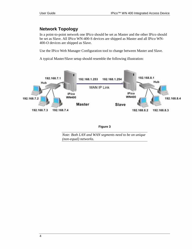
Network TopologyIn a point-to-point network one IPico should be set as Master and the other IPico shouldbe set as Slave. All IPico WN-400-S devices are shipped as Master and all IPico WN-400-O devices are shipped as Slave.
Use the IPico Web Manager Configuration tool to change between Master and Slave.
A typical Master/Slave setup should resemble the following illustration:
Figure 3
Note: Both LAN and WAN segments need to be on unique(non-equal) networks.

IPico™ WN 400 Integrated Access Device User Guide
5
Placing CallsTo place a call, dial the four-digit number of the extension that you wish to reach. Thefour-digit extension number has two parts: the leading digits of the IPico device, followedby the port number, as shown in Figure 4. You may change the leading numbers of theIPico devices. Please refer to the section titled Web Manager Configuration Tool to learnhow to change the leading digits.
Inter-site Telephony Connection
Setup
Figure 4
Plug analog telephones into Ports 0-3 of the IPico units. You may also attach a facsimilemachine to any of the ports.
Note: It is not necessary to attach a telephone or faxmachine to each port; you may use as many or as few asyou wish.
Placing a CallTo place a call, lift the handset, wait for a dial tone, and dial the leading digits, followedby the port number (see Figure 4) of the extension that you wish to reach. In Figure 4, toreach the extension on Port 0 attached to the IPico device on the left, lift the handsetconnected to either IPico device and dial the leading digits (200), followed by the portnumber (0). For example, to reach the extension on Port 3 attached to the IPico unit onthe right, dial ‘3003’.

User Guide IPico™ WN 400 Integrated Access Device
6
Remote PBX Connection
Setup
Figure 5
Connect Ports 0-3 of first IPico unit to the outgoing lines (analog trunks) of the PBX (leftside in diagram), and connect analog telephones to Ports 0-3 of the second IPico unit.You may also choose to connect handsets to any unused ports on the IPico that isconnected to the PBX.
Note: It is not necessary to attach a telephone or faxmachine to each port; you may use as many or as few asyou wish.
Placing a CallTo place a call to the PBX from an extension connected to an IPico device, lift a handsetand dial a four-digit extension (the leading digits of the remote IPico unit, followed bythe port number) of any FXS port connected to the PBX. In the system illustrated below,you can dial ‘2000’ to reach the PBX. You will connect to the PBX as if you had calledfrom an external location.
To place a call from extensions connected to the PBX to an extension connected to anIPico device, dial the extension of the outside line connected to the IPico unit (assignedby the PBX) and then dial the four-digit IPico extension of the party you wish to reach.
For example, from the PBX extension, you would dial ‘8’ (or whichever prefix your PBXhas assigned to the IPico device) to connect to the IPico unit, and then the four-digitextension of the party you wish to reach. For example, to reach the extension connectedto Port 3 of the IPico unit in the illustration below, you would dial ‘8-3003’.
Note: Please refer to PBX documentation for PBXconfiguration information.

IPico™ WN 400 Integrated Access Device User Guide
7
Remote PSTN (Public Switched Telephone Network) Connection
Setup
Figure 6
Connect Ports 0-3 of the IPico WN400-O to PSTN lines, and connect analog telephonesto Ports 0-3 of the IPico WN400-S.
Note: It is not necessary to attach a telephone or faxmachine to each port; you may use as many or as few asyou wish.
Placing a CallTo place a call from the IPico WN400-S to the PSTN, lift the handset and dial anyoutside number you wish to reach. There is a one-to-one relationship between FXS portsand FXO ports. For example, to place a call on the PSTN from the telephone setconnected to Port 0 on the WN400-S, pick up the receiver and dial the number. The callwill be routed through the telephone line that is connected to Port 0 on the WN400-O.
Note: No leading digits or a prefix are required to dial aWN400-O.
Any incoming call to telephone lines that are connected to IPico FXO will automaticallybe routed to the matching port number on the FXS. For example, if Port 0 on the FXO isconnected to telephone line 212-555-6353, any calls made to this number will be directedto the telephone connected to Port 0 on the IPico FXS.

User Guide IPico™ WN 400 Integrated Access Device
8
Remote PBX Extension
Setup
Figure 7
Connect Ports 0-3 of the WN400-S (FXS) IPico unit to the extension lines of the PBX(left side in diagram), and connect analog telephones to Ports 0-3 of the WN400-S (FXS)IPico unit.
Note: It is not necessary to attach a telephone or faxmachine to each port; you may use as many or as few asyou wish.
Placing a callTo place a call to the PSTN through the PBX from an extension connected to the IPicoWN400-S, lift the handset and dial the prefix required by the PBX to get an outside line.You will connect to the PBX as if you had called from a PBX extension.
Note: Please refer to PBX documentation for PBXconfiguration information.

IPico™ WN 400 Integrated Access Device User Guide
9
Configuration
Web Manager Configuration Tool
Accessing the unit1. Connect your PC to the IPico WAN port either by plugging both your PC and the
IPico WAN port to a hub or by connecting them with a crossover cable.
2. Accessing the unit is through the network. If you cannot reach the IPico, use theCOMmander to set the IP addresses. See Appendix A for default IP addresses.
3. Start your Web browser application and enter the IPico WAN IP address.
4. On the login prompt, enter the password. See Appendix A for passwords.
ParametersThe following explains how to configure both WN400-S (FXS) and WN400-O (FXO).
Figure 8

User Guide IPico™ WN 400 Integrated Access Device
10
LAN IP AddressThis address must be assigned to the IPico unit if you are using the IPico unit to routedata from workstations on your LAN. This address should be unique and must not beassigned to any other device on your LAN.
Note: Normally the default gateway of the devices on yourLAN should point to this address as well.
LAN Network MaskThe mask defines the address space assigned to your LAN segment. This mask shouldmatch the one used by other devices on your LAN.
Master/SlaveYou can assign a device to be a Master or a Slave by selecting Device Type. In a point-to-point topology, one IPico must be the Master and the other must be the Slave.
Note: Changes to the Master/Slave configuration will alsochange the WAN IP address, the default gateway, and theleading digits settings of the device.
Quality of ServiceQuality of Service ensures that voice traffic over the network is given priority over datatraffic. You can control the amount of bandwidth that you would like to reserve for voiceand data traffic over the WAN link.
Outbound CIR
This parameter allows you to limit the total amount of bandwidth that flows from theIPico WAN interface to the wireless link. You should assign a value that matches the truelink capacity (throughput) while considering the fact that the traffic usually flows in bothdirections, uplink and downlink. For example, a wireless link of 11 Mbps can normallydeliver 8 Mbps (throughput). Since the link is usually symmetrical, you should considertraffic of 4Mbps in each direction. In this case, you should enter the value 4000. In caseswhere no limitation is required, put ‘0’ (zero) or the word ‘unlimited’.
Data CIR
This parameter sets the amount of data (not voice) traffic that flows from the IPico WANinterface to the wireless link. This value must be less than the Outbound CIR value, or‘unlimited’ if the Outbound CIR is ‘unlimited’. The difference between the Data CIR andthe Outbound CIR is that the Data CIR limits the amount of bandwidth for voice over thelink. Consider the fact that a G.729a call requires 13 Kbps, including overhead, and leavean adequate margin for the required simultaneous voice calls, as shown in the followingequation:
Outbound CIR – Data CIR ≥≥≥≥ n * 13
Where ‘n’ equals the number of simultaneous calls (e.g. 4).

IPico™ WN 400 Integrated Access Device User Guide
11
Figure 9
Leading Digits (FXS Only)In order to place a call from one FXS port to another, each FXS port is identified by afour-digit number. The four-digit number is comprised of the IPico leading digits (threedigits) and the port number (one digit between 0 and 3), as shown in Figure 4.
The default leading digits can be found in Appendix A.
Note: the IPico WN400-O (FXO) devices do not requireleading digits because they are not connected to telephonesets.
WANSee Network Setup. The WAN parameters should change only if you have a routerbetween the two IPico units.
WAN Netmask
This is the address space assigned to your WAN. This value should match the one usedby other devices on your WAN.
Master IP Address
Enter the IP address of the Master IPico WAN interface. To avoid conflicts with othernodes on your network, this address must not be assigned to any other node on yourWAN or LAN, including the Slave.
User Guide IPico™ WN 400 Integrated Access Device
12
Slave IP Address
Enter the IP address of the Slave IPico WAN interface. To avoid conflicts with othernodes on your network, this address must not be assigned to any other node on yourWAN or LAN, including the Master.
Default Gateway
Enter the IP address of the WAN gateway. If you have a third-party router on your WAN,enter its IP address here. If you do not have a router, this address should be the WAN IPaddress of the peer IPico device on your network.
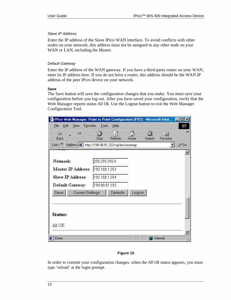
SaveThe Save button will save the configuration changes that you make. You must save yourconfiguration before you log out. After you have saved your configuration, verify that theWeb Manager reports status All Ok. Use the Logout button to exit the Web ManagerConfiguration Tool.
Figure 10
In order to commit your configuration changes, when the All Ok status appears, you musttype ‘reload’ at the login prompt.

IPico™ WN 400 Integrated Access Device User Guide
13
Note: An improper combination of values will generate anerror warning at the bottom of the screen after you press‘save’. You will be required to enter a proper combinationof values and save again. For more information aboutthese error messages, see the Error Messages appendix.
Current SettingsThis button will display the last saved settings.
DefaultsThis button will restore factory default settings.
COMmander Configuration ToolThe COMmander is a serial configuration tool that should be used when the IP address ofthe IPico is not known. The COMmander tool allows you to change the IP parameters tothe default settings or to any other required value. Note: changes are saved and take effectimmediately after new settings are entered.
1. Using a crossover serial cable, connect a laptop or a workstation to the IPico unit.You may use either serial port, COM1 or COM2.
2. From Windows 95/98/2000, click Start, then click Run.
3. In Open, type ‘Hypertrm.exe’ to start HyperTerminal.
4. Choose a name for your IPico connection (any name will do).
5. Click the Connect using dropdown menu and choose the serial port (COM) yourserial cable is connected to.
6. Change port settings as detailed in Appendix A.
7. Click Dial.
8. At the login prompt, type the COMmander login (see Appendix A). After youauthenticate, you will see this screen:

User Guide IPico™ WN 400 Integrated Access Device
14
Figure 11
1. Press ‘1’ to enter the new LAN IP and LAN Netmask
2. Press ‘2’ to enter the new WAN IP and WAN Netmask
3. Press ‘3’ to enter the IP address of the default gateway.
4. Press ‘S’ or ‘M’ to bring the IPico settings to the (S)lave or (M)aster defaultvalues.
5. Press ‘Q’ to (Q)uit.
IPico™ WN 400 Integrated Access Device User Guide
15
Specifications
Indicators, Interfaces, and Controls• Green LED on the front panel indicates POWER–ON.
• ON/OFF switch on the power supply unit.
• White button on the rear panel controls power to the IPico.
• COM1 (DB9) on the rear panel interface is used for serial configuration.
• LAN interface on the rear panel (RJ-45) is used to connect the IPico TM to theoffice LAN.
• WAN interface on the rear panel (RJ-45/PCMCIA) is used to connect the IPico TMto the IP link (wireless modem).
• The telephone ports (4 x RJ-11) are used to connect the IPico TM as follows: FXSto telephone or PBX outgoing line.
• FXO to analog PSTN or PBX extension.
Product Capabilities• Shares bandwidth dynamically between voice and data users
• Accommodates additional voice ports
• Integrates easily with existing local PBX
• Generates raw billing reports, minutes per phone number, and byte count perinternal IP address
• Allocates bandwidth per IP address
• Supports Network Address Translation (NAT)
Voice Support• Single-stage dialing
• Silence suppression
• Automatic fax detection (AFD)
• Dial, busy, fast busy, and ringback tones
• G.168 Automatic Echo Cancellation
• Adjustable jitter buffer length to accommodate delayed voice packets
Management Features• Web-based management system
• ASCII terminal
User Guide IPico™ WN 400 Integrated Access Device
16
• Network manageable
• Remote-upgradeable software
Security Features• Advanced security and password authentication
• Powerful firewall to protect the internal LAN from external intrusion
Interfaces• Four FXS/FXO voice ports (RJ-11)
• 10/100BaseT Ethernet LAN Interface (RJ-45)
• 10/100BaseT Ethernet WAN Interface (RJ-45)
Standards and Protocols Supported• ITU standard voice codecs (G.729a, G.711) for excellent voice quality at low data
rates
• Industry-standard voice protocols SIP and H.323 v2
• G.711 codec for transparent fax transmissions
• Differentiated Services (DiffServ) protocol for voice prioritization

IPico™ WN 400 Integrated Access Device User Guide
17
Troubleshooting
Dialing and Placing Calls1. I do not hear a dial tone (WN400-S only).
• Make sure you waited 60 seconds after reboot.
• Verify that the telephone set is properly connected to your IPico device.
• Hang up and try placing your call again.
• Try rebooting.
2. After dialing to a WN400-S (FXS) , I do not hear a ringback tone.• Verify that your Master/Slave settings are configured correctly.
• The WN400-S you are trying to reach may be inaccessible. Verify that yournetwork settings are configured correctly. Please refer to the Network Problemssection.
3. After dialing to a WN400-O (FXO) , I do not hear a ringback tone.• The WN400-O you are trying to reach may be inaccessible. Verify that your
network settings are configured correctly. Please refer to the Network Problemssection.
• The FXS port does not match the connected FXO port.
• The FXO port is not connected to the PSTN or to a PBX extension.
4. After dialing an extension number, I hear a ringback tone, but the telephone Iam dialing does not ring.
• Using the Web Manager, verify that you are using the correct leading digits of theextension you are trying to reach.
• Verify that you are dialing the correct port number of the extension you are tryingto reach.
5. After dialing an extension number, I hear a busy signal.• The extension number you are calling may be busy.
• You may have both IPico devices set as either Master or Slave.
• Verify that your QoS settings are not too restrictive: If your Outbound Data CIRparameter is too high, you may have allocated too little bandwidth for voice traffic,and therefore you will not be able to make the call. Check both IPico devices.
• You may have called the same extension you are dialing from.
User Guide IPico™ WN 400 Integrated Access Device
18
Using COMmander1. HyperTerminal will not respond
• Try pressing <Enter> twice.
• Verify that you are using correct port settings as detailed in Appendix A. Pleaserefer to the Changing the Master/Slave Setting Using COMmander section.
• The serial cable is not properly connected.
• Try using the alternative serial port on your IPico device.
• The serial cable may not be a two-way crossover cable.
2. I cannot log in to COMmander• Verify that you are using the COMmander password as your password login (see
Appendix A).
3. I encountered the following system error: ‘SIOCADDRT: Network isunreachable’. What do I do ?
• You probably entered incorrect IP address settings. Verify that IPico’s LAN IPaddress is different from the WAN IP address. IPico’s default gateway IP addressmust either be on the LAN subnet or the WAN subnet (usually on the WANsubnet).
Using the Web Manager1. I cannot log in to the Web Manager from my browser application.
• Verify that your network settings are configured correctly. Please refer to the nextsection, Network Problems.
• Verify that you are using the WEB password as your password login
2. My new settings are not permanently saved• You probably did not click the Save button before logging out.
• There might have been an error. Make sure you see the ‘All OK’ message.
• Try rebooting.
3. I encountered a system error. What do I do?• You probably entered incorrect IP address settings. Verify that IPico’s LAN IP
address is different from the WAN IP address. IPico’s default gateway IP addressmust be on either the LAN subnet or the WAN subnet.
4. Changes do not take effect• After saving your new settings and logging out, you did not log back in using
reload as password login.
• Try rebooting.

IPico™ WN 400 Integrated Access Device User Guide
19
Network Problems1. I cannot access my IPico device from the network.
• Verify that IPico’s IP address is on the same network as your PC client. Please referto the section titled IP Address Configuration.
• Verify that the subnet mask is the same as your PC client. Please refer to the sectiontitled IP Address Configuration.
• Verify that the IPico interface is connected to your PC.
• Try replacing the Ethernet cables.
• Try restarting with new network settings.
2. I cannot access my network across the WAN.• Verify that the IP address you are trying to reach is accessible across the LAN.
• Check your default gateway setting and verify it has the LAN IP address of theIPico.
• Verify that the subnets of the two LANs are not the same.
• Verify that the IPico’s default gateway setting is set either to your router’s LAN IPaddress or to the other IPico’s WAN IP address. Do this on both LANs.
3. I forgot the IP address of my IPico device and now I cannot reach the WebManager.
• You will need to use COMmander to reset your IP address configuration. Pleaserefer to the section titled IP Address Configuration Using COMmander.
Quality of Service (QoS)1. Voice quality is poor.
• Check your Outbound Total CIR and Outbound Data CIR settings. You shouldallow at least 13 Kbps on both IPico devices for each telephone call.
• If your WAN connection is a wireless link, make sure the link is up and stable.
2. Data throughput seems to be too low.• Check your Outbound Total CIR and Outbound Data CIR settings on both IPico
devices. Please refer to the section entitled Quality of Service Options under Initialand Subsequent Configuration – Web Manager Configuration Tool.
• If your WAN connection is a wireless link, make sure the link is up and stable.

User Guide IPico™ WN 400 Integrated Access Device
20
Error MessagesNot supported in this version.This warning indicates that one of the fields is not supported in this release, and its valuewill be ignored.
Missing or invalid field.This warning indicates that one of the fields was left empty or that one of the values youentered is invalid.
The invalid or missing value will be ignored.
No Quality of Service defined.This warning indicates that no Quality of Service information was entered and thereforethere will be no Quality of Service enforcement.
Ignoring invalid parameter.This warning indicates that an invalid parameter will be ignored and will not be saved.
This warning indicates that although the changes were saved, they were not executed.This is caused when you use the WWW Manager over a network. Changing IP addressesin this situation might cause the connection to be lost.
You may enter a special password in the Login Screen to force the execution of thevalues.
Some of the required fields are invalid or missing.A required field is either missing or invalid. The requested operation will not beprocessed until the field is valid.
Unknown Action.This error indicates that what you requested is not known to the system. This usuallyindicates some serious error in the installation of the system.
Unable to process your request.This error indicates that the operation requested was not successful. This usuallyindicates a problem with the installation of the system.
Delete entry first.This error indicates that you attempted to save a new entry that already exists. Youshould remove the old entry first.
Invalid IP address.The IP address you entered is invalid. IP addresses should be entered as 4 numbersbetween 0–255 separated by periods, e.g., 192.168.1.1.

IPico™ WN 400 Integrated Access Device User Guide
21
Invalid telephone number.The telephone number you entered is invalid. A telephone number should contain digitsonly. You should not put any type of separator between the digits such as spaces,hyphens, or periods.
IP address is multicast.The IP address you entered is a multicast address. Multicast addresses are IP addresseslarger than 224.0.0.0, and are not allowed.
Invalid mask address.The mask you entered is invalid. A valid mask is a mask that, when converted to binary,contains a series of ones followed by a series of zeros (read from left to right), e.g.,255.255.255.0.
Invalid password.The password you entered is incorrect.
Not authorized or password timeout.Normally, this error means that there has been a timeout since your last login. You shouldlog in again.
Telephone number already exists.The telephone number you wanted to add already exists in the database.
Invalid CIR, should be between 1 Kbps and 102400 KbpsYou entered an invalid CIR. You should enter a number between 1–102400 Kbps, orenter ‘0’ or ‘unlimited’ to disable QoS.
IP address is not in the correct IP subnet.The IP address you entered is not the correct subnet.
System Error!System error. This means that the system tried to execute the new values you entered butfailed.

User Guide IPico™ WN 400 Integrated Access Device
22
Appendix A
Version NumberThis document refers to release 2.0.2-1
Factory settingsMaster Slave
WAN IP 192.168.1.253 192.168.1.254LAN IP 192.168.7.1 192.168.8.1WAN Netmask 255.255.255.0 255.255.255.0LAN Netmask 255.255.255.0 255.255.255.0
Leading digits 200 300
Serial ParametersParameter ValueBits per second: 9600Data bits: 8Parity: NoneStop bits: 1Flow control: None
PasswordsApplication PasswordWeb configuration tool ipicoCOMmander configuration tool ipico-conf

IPico™ WN 400 Integrated Access Device User Guide
23
LIMITTED WARRANTY1. Hardware Warranty: Lucid Voice Ltd. (“Lucid”) warrants with respect to hardware, that the product
and/or systems and any part thereof supplied and to which this Warranty applies (the “Systems”) will,when properly installed, conform to LUCID’s published specifications and that the Systems will be freefrom defects in workmanship and materials under normal use and service (“the Hardware Warranty”),for a period of twelve (12) months following the date of delivery thereof (the “ Hardware WarrantyPeriod”), subject to LUCID .being provided with a written notice of defect during the HardwareWarranty Period.
2. Upon receipt of such notice, LUCID shall investigate any such warranty claim to determine the natureand cause of such defect(s) if any. If such investigation establishes the existence of defects covered bythis Hardware Warranty LUCID shall authorize the sending of the System or part thereof. Systemsreturned to LUCID must be sent prepared, insured and packaged appropriately for safe shipment atcustomer expense. LUCID shall at its option and expense replace or repair the defective System or partthereof. The repaired or replaced Systems will be shipped to customer at LUCID’s expense, if LUCID isliable under the Hardware Warranty, not later than 30 business days after receipt by LUCID.
3. Systems replaced or repaired during the Original Warranty Period will carry a warranty of 6 months fromdate of replacement or repair or until end of Original Warranty Period, whichever is the later.
4. Software Warranty: LUCID warrants with respect to software that the software programs embedded inthe System and licensed from LUCID will perform in substantial conformance to the programdocumentation (“the Software Warranty”) for a period of 90 days following the date of deliverythereof (the “Software Warranty Period”) subject to LUCID being provided with a written notice ofdefect during the Software Warranty Period.
5. Upon receipt of such notice LUCID shall investigate any such warranty claim to determine the natureand cause of such defect(s) if any. If the software does not operate in accordance with the SoftwareWarranty LUCID’s sole responsibility hereunder shall be, at its option and expense, to replace or repairthe software that does not comply with the Software Warranty within a reasonable period of time.Customer assumes responsibility for the selection of appropriate applications programs and associatedreference materials. LUCID expressly excludes any warranty that its Systems will work in combinationwith any hardware or application software products provided by third parties. For any third party’ssoftware specified in LUCID specifications for the Systems as being compatible with LUCID Systems,LUCID will make reasonable effort to provide compatibility, except where the non-compatibility iscaused by a defect in the third party’s product. LUCID expressly excludes that the operation of thesoftware programs will be uninterrupted or error-free, or that all defects in the software programs will becorrected.
6. If the transaction for LUCID Systems is done through an authorized Distributor, replacement, repair andall other services provided under these Hardware and Hardware warranty shall be done through suchauthorized Distributor.
7. Standard telephone support may be obtained by calling LUCID service department within the Hardwareand Software warranty period.
8. OTHER THAN THOSE WARRANTIES SET FORTH IN PARAGRAPH 1 AND 4, LUCIDSPECIFICALLY DISCLAIMS ALL WARRANTIES EXPRESS OR IMPLIED, INCLUDING BUTNOT LIMITED TO, IMPLIED WARRANTIES OF MERCHANTABILITY AND FITNESS FOR APARTICULAR PURPOSE WITH RESPECT TO DEFECTS IN THE SYSTEMS AND ANYPARTICULAR APPLICATION OR USE OF THE SYSTEMS. IN NO EVENT SHALL LUCID BELIABLE FOR ANY LOSS OF PROFIT OR ANY OTHER COMMERCIAL DAMAGE, INCLUDINGBUT NOT LIMITED TO, SPECIAL, INCIDENTAL, CONSEQUENTIAL OR OTHER DAMAGESEVEN IF LUCID WAS AWARE OF THE POSSIBILITY OF SUCH DAMAGES.
9. This warranty shall not cover ordinary wear and tear of the Systems or other defects due tocircumstances beyond LUCID’s control such as chemical, electro-mechanical or electrical influences anddamages or by accident, fire or other hazards. This warranty shall not cover defects due to interference oroperating of the System by unauthorized customer or any other unauthorized third party, whichauthorization will only be given in writing at LUCID’s sole discretion. LUCID shall not be liable underthis warranty if its testing and examination disclose that the alleged defects in the Systems and any partthereof does not exist or was caused by customer’s or any unauthorized third party’s misuse, negligent,improper installation or testing, unauthorized attempts to repair, or any other cause beyond the range ofintended use.
10. THE WARRANTIES STATED HEREIN ARE EXCLUSIVE AND ARE EXPRESSLY IN LIEU OF ALL OTHER WARRANTIES,EXPRESSED OR IMPLIED, INCLUDING, BUT NOT LIMITED TO, THE IMPLIED WARRANTY OF MERCHANTABILITYOR FITNESS FOR A PARTICULAR PURPOSE.

User Guide IPico™ WN 400 Integrated Access Device
24
11. Beyond the Hardware or the Software warranty period, LUCID shall repair or replace defective Systemsor parts thereof according to its standard price list relevant at such time. Systems or parts thereof thusrepaired or replaced shall carry a warranty of 6 months.
12. The supply of spare parts at reasonable costs shall be available for a period of seven (7) years from thedate of delivery.