IPC-1331 Volntary Safety Standard for Electrically Heated Process Equipment
14
IPC-1331 Voluntary Safety Standard for Electrically Heated Process Equipment ASSOCIATION CONNECTING ELECTRONICS INDUSTRIES 2215 Sanders Road, Northbrook, IL 60062-6135 Tel. 847.509.9700 Fax 847.509.9798 www.ipc.org IPC-1331 March 2000 A standard developed by IPC
-
Upload
cristian-molder -
Category
Documents
-
view
18 -
download
2
description
Voluntary Safety Standard for Electrically Heated Process Equipment
Transcript of IPC-1331 Volntary Safety Standard for Electrically Heated Process Equipment
IPC-1331
Voluntary Safety Standard
for Electrically Heated
Process Equipment
ASSOCIATION CONNECTINGELECTRONICS INDUSTRIES
2215 Sanders Road, Northbrook, IL 60062-6135Tel. 847.509.9700 Fax 847.509.9798
www.ipc.org
IPC-1331March 2000 A standard developed by IPC

The Principles ofStandardization
In May 1995 the IPC’s Technical Activities Executive Committee adopted Principles ofStandardization as a guiding principle of IPC’s standardization efforts.
Standards Should:• Show relationship to Design for Manufacturability
(DFM) and Design for the Environment (DFE)• Minimize time to market• Contain simple (simplified) language• Just include spec information• Focus on end product performance• Include a feedback system on use and
problems for future improvement
Standards Should Not:• Inhibit innovation• Increase time-to-market• Keep people out• Increase cycle time• Tell you how to make something• Contain anything that cannot
be defended with data
Notice IPC Standards and Publications are designed to serve the public interest through eliminatingmisunderstandings between manufacturers and purchasers, facilitating interchangeability andimprovement of products, and assisting the purchaser in selecting and obtaining with minimumdelay the proper product for his particular need. Existence of such Standards and Publicationsshall not in any respect preclude any member or nonmember of IPC from manufacturing or sell-ing products not conforming to such Standards and Publication, nor shall the existence of suchStandards and Publications preclude their voluntary use by those other than IPC members,whether the standard is to be used either domestically or internationally.
Recommended Standards and Publications are adopted by IPC without regard to whether theiradoption may involve patents on articles, materials, or processes. By such action, IPC doesnot assume any liability to any patent owner, nor do they assume any obligation whatever toparties adopting the Recommended Standard or Publication. Users are also wholly responsiblefor protecting themselves against all claims of liabilities for patent infringement.
IPC PositionStatement onSpecificationRevision Change
It is the position of IPC’s Technical Activities Executive Committee (TAEC) that the use andimplementation of IPC publications is voluntary and is part of a relationship entered into bycustomer and supplier. When an IPC standard/guideline is updated and a new revision is pub-lished, it is the opinion of the TAEC that the use of the new revision as part of an existingrelationship is not automatic unless required by the contract. The TAEC recommends the useof the lastest revision. Adopted October 6. 1998
Why is therea charge forthis standard?
Your purchase of this document contributes to the ongoing development of new and updatedindustry standards. Standards allow manufacturers, customers, and suppliers to understand oneanother better. Standards allow manufacturers greater efficiencies when they can set up theirprocesses to meet industry standards, allowing them to offer their customers lower costs.
IPC spends hundreds of thousands of dollars annually to support IPC’s volunteers in thestandards development process. There are many rounds of drafts sent out for review andthe committees spend hundreds of hours in review and development. IPC’s staff attends andparticipates in committee activities, typesets and circulates document drafts, and follows allnecessary procedures to qualify for ANSI approval.
IPC’s membership dues have been kept low in order to allow as many companies as possibleto participate. Therefore, the standards revenue is necessary to complement dues revenue. Theprice schedule offers a 50% discount to IPC members. If your company buys IPC standards,why not take advantage of this and the many other benefits of IPC membership as well? Formore information on membership in IPC, please visit www.ipc.org or call 847/790-5372.
Thank you for your continued support.
©Copyright 2000. IPC, Northbrook, Illinois. All rights reserved under both international and Pan-American copyright conventions. Anycopying, scanning or other reproduction of these materials without the prior written consent of the copyright holder is strictly prohibited andconstitutes infringement under the Copyright Law of the United States.

IPC-1331
Voluntary Safety Standard
for Electrically Heated
Process Equipment
Developed by the Health and Safety Subcommittee (4-32) of theEnvironmental Health and Safety Committee (4-30) of IPC
Users of this standard are encouraged to participate in thedevelopment of future revisions.
Contact:
IPC2215 Sanders RoadNorthbrook, Illinois60062-6135Tel 847 509.9700Fax 847 509.9798
ASSOCIATION CONNECTINGELECTRONICS INDUSTRIES
AcknowledgmentAny Standard involving a complex technology draws material from a vast number of sources. While the principal membersof the Health and Safety Subcommittee (4-32) of the Environmental Health and Safety Committee (4-30) are shown below,it is not possible to include all of those who assisted in the evolution of this standard. To each of them, the members of theIPC extend their gratitude.
Environmental Health andSafety Committee
Health and SafetySubcommittee
Technical Liaisons of theIPC Board of Directors
ChairmanJohn LottE.I. DuPont
ChairmanLee WilmotHadco
Stan PlzakPensar Corp.
Peter BigelowBeaver BrookCircuits Inc.
Health and Safety Subcommittee
Collingham, Mark E., Griffin Ltd.
Girard, Joan, Electrotek Corp.
Heth, Michael, Allied Signal
Hoium, Brad, Advanced Flex Inc.
Lundquist, Robert, MNTAP (MNTechnical Assistance Prog.)
Scott, Tim, Tyco Printed CircuitGroup
Sella, Alon, Micro-Swiss
Tremblay, Russell J., M/A-COM Inc.
IPC-1331 March 2000
ii

Voluntary Safety Standard for ElectricallyHeated Process Equipment
1 SCOPE
This voluntary standard establishes minimum requirementsfor the design, installation, operation and maintenance ofelectrically heated process equipment in order to minimizeelectrical hazards and prevent fires that may occur in com-bustible tanks, tank liners and drying equipment. It isintended to cover both liquid and gas (e.g., air) processheaters used in the manufacture of printed wiring boards(PWBs) and printed wiring assemblies (PWAs). Minimumrequirements are indicated by the use of the term ‘‘shall.’’
Please note: This standard does not purport to address allsafety issues associated with its use. Users should establishappropriate safety and health practices and determine theapplicability of regulatory limitations prior to standard’suse.
2 REFERENCE DOCUMENTS
2.1 This Standard is intended to be compliant with thefollowing regulations and codes:
29 CFR 1910 Subpart S-Electrical
ANSI C2-1997 National Electrical Safety Code
NFPA 70 National Electrical Code, Article 427 of NationalElectric Code
NFPA 79 National Fire Prevention Association
UL 499 Electric Heating Appliances
CSA C22.2 No. 88-1958 Industrial Heating Equipment
CEmark
3 GENERAL APPLICATION AND USE
3.1 Electric immersion heaters are generally used to heataqueous or semi-aqueous solutions. They are not recom-mended for use with flammable solutions andshall not beused with class 1 or 2 flammable liquids.
3.2 Users shall verify with equipment and/or heatermanufacturer and chemical supplier(s) that heater sheathmaterial is compatible with the intended solution beforeinstallation and use. If user changes chemical composition,usershall ensure that heater sheath material is compatiblewith the new solution by checking with equipment and/orheater manufacturer.
3.3 Electric immersion heaters may ignite combustibletanks or liners. To prevent ignition, heating elementsshallbe securely mounted in a manner that prohibits direct con-tact with the tank or tank liner. Heating elementsshall belocated at least 25 mm [0.984 in] from the tank bottom andsidewalls or minimum distance recommended by manufac-turer.
3.4 Electric heating elements, used in both liquid and gasprocess heating applications,shall be equipped with appro-priate and adequate supports to prevent contact with com-bustible surfaces as a result of heating element deflectionor sag due to use.
3.5 Electric immersion heatersshall be protected fromphysical damage. Theyshall be shielded or located to pre-vent physical damage from contact with other items enter-ing tanks such as anodes, cathodes, racks, product, concen-trated chemicals, and/or electrically charged components.Protectionshall be accomplished by proper placement orappropriate guarding.
3.6 Heater elementsshall be allowed to cool before theyare removed from equipment for service or replacement.
3.7 Tanksshall not be drained until heater element hascooled.
3.8 Electric heating devicesshall be built and tested tocomply with a nationally recognized independent testinglaboratory specification, Underwriters Laboratories (UL)and Factory Mutual (FM), for their intended application.
4 DESIGN AND INSTALLATION REQUIREMENTS
Electrically heated process equipmentshall comply withthe following design and installation requirements:
4.1 Control Circuit Design
4.1.1 A corrosion-resistant temperature-sensing element,such as a thermocouple, thermistor, or resistance thermaldevice (RTD), shall be used in conjunction with atemperature-indicating controller (see 4.1.2). The use of athermostat with set point indication is also permitted. Allsensing elementsshall be compatible with the environmentin which they are used (i.e., bath chemistry, fumes, orvapors) or be housed in a chemically compatible thermow-ell.
March 2000 IPC-1331
1

4.1.2 A temperature-indicating controller with both sen-sor break and short protection that provides an indicationof process set pointshall be used to provide temperaturesensor open and short circuit protection. The controllershall allow the power control device (see 4.1.3) to beswitched off when the tank temperature reaches the setpoint or when the system is not being used. A controllerthat displays the set point and the actual temperature at thesame time is preferable because it allows an immediateevaluation of the system condition.
4.1.3 An appropriately sized power control device, suchas a contactor relay, solid state relay (SSR), or silicon con-trolled rectifier (SCR),shall be used for controlling theavailability or the amount of electrical power to the processheater.
4.1.4 All liquid process heater elementsshall contain athermal limit device, such as a fusible link, bimetallic ther-mostat, or other temperature regulating device, to detect anover-temperature condition in all installations where thepossibility of combustion exists. The deviceshall disablepower flow to the heating elements in the event of an over-temperature condition. This device may be non-resettable,manually reset, or automatically reset. If the device auto-matically resets, power flow to the heating elementsshallbe restricted from automatically resuming through use ofmanual latching circuit. Please note that the type of thermallimit device used will depend upon the technologiesemployed.
4.1.5 A temperature-sensing deviceshall be provided toprotect electrically heated process equipment from over-temperature conditions. This deviceshall disable powerflow to all heating elements in the event of an over-temperature condition. This deviceshall be unique to andredundant with the temperature-sensing element specifiedin 4.1.1. This device may be a pre-set temperature switchor a temperature-sensing element, such as a thermocouple,thermistor, or resistance thermal device (RTD) and itsattendant hi-limit controller. The set point of this over-temperature deviceshall be set at a temperature value thatis less than the maximum temperature limit of the equip-ment (i.e., when reached, no damage will occur to thechamber, lining, vessel or any other component containedwithin).
4.1.6 If an adjustable device or controller is used, themaximum adjustment position that is availableshall be nogreater than the equipment’s maximum temperature limit(i.e., when reached, no damage will occur to the chamber,lining, vessel or any other component contained within).
4.1.7 If exothermic chemistries are present in the processvessel, the over-temperature device and associated coolingequipmentshall be set at a temperature value to ensure that
the exothermic action is controlled. The over-temperatureset point for such chemistriesshall be lower than the maxi-mum temperature limit dictated by the materials of con-struction of the vessel or chamber used (i.e., when reached,no damage will occur to the chamber, lining, vessel or anyother component contained within). Please note that theover-temperature limitshall be non-resettable to preventresetting to an unsafe temperature, such as a temperaturethat is above an exothermic temperature.
4.1.8 An over-temperature controller for the over-temperature sensing device specified in 4.1.5shall disablepower flow to all heating elements in the event of an over-temperature condition. This over-temperature controllermay be non-resettable, manually reset, or automaticallyreset. If the controller automatically resets, power flow tothe heating elementsshall be restricted from automaticallyresuming by the use of a manual latching circuit. The over-temperature controllershall activate a visible light and/oraudible alarm to signal that an over-temperature conditionexists.
4.1.9 For liquid tank heaters, a low-level switchshall beincluded in the electrical control circuit to disable theheater circuit power whenever the process liquid leveldrops to less than 25 mm [0.984 in] above the heater ele-ments’ hot zone. This switchshall also be equipped with avisible light and/or audible alarm to indicate that the switchhas been activated. It is recommended that users chooselow-voltage control circuits for monitoring low-level liquidsensors to prevent risk of shock.
4.1.10 For gas (e.g., air) process heaters, a low-flowswitch shall be included in the electrical control circuit todisable the heater circuit power whenever the process gas(e.g., air) flow drops to a value just above the minimumflow required by the heating elements’ manufacturer forgas (e.g., air) process heaters. This switchshall also beequipped with a visible light and/or audible alarm to indi-cate that the switch has been activated.
4.1.11 A separate safety interrupt contactorshall beincluded in the electrical control circuit and be wired inseries with the thermally-used heater elements specified in4.1.4 and activated by the temperature-sensing devicespecified in 4.1.5, the over-temperature controller specifiedin 4.1.6, the low liquid level switch specified in 4.1.9, orthe low-flow switch specified in 4.1.10. This contactorshall be separate from the power control device sepcifiedin 4.1.3 to interrupt power flow to all heating elements inthe case of an over-temperature condition.
4.1.12 An enable switch or process set pointshall beincluded in the electrical control circuit to disable the heat-ing control (not the safety interrupt controls) if processcooling is utilized in addition to process heating.
IPC-1331 March 2000
2
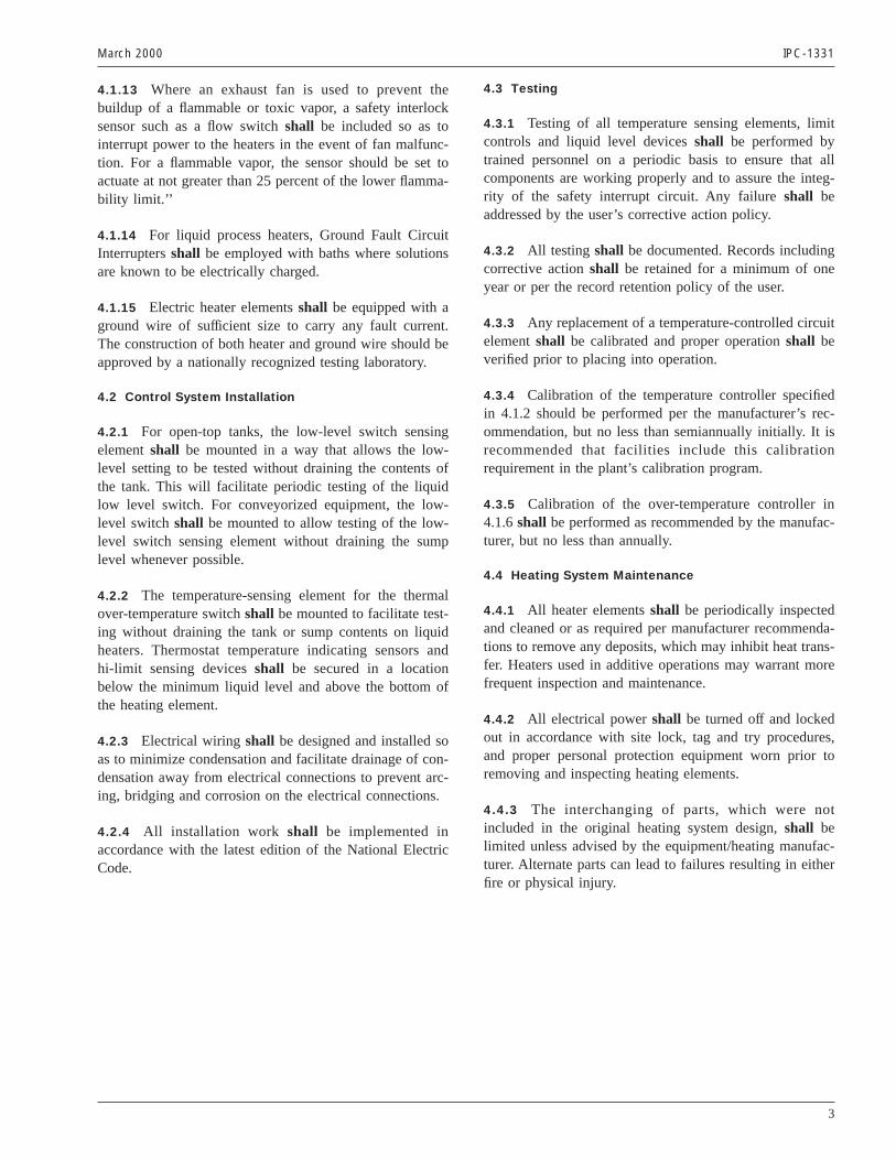
4.1.13 Where an exhaust fan is used to prevent thebuildup of a flammable or toxic vapor, a safety interlocksensor such as a flow switchshall be included so as tointerrupt power to the heaters in the event of fan malfunc-tion. For a flammable vapor, the sensor should be set toactuate at not greater than 25 percent of the lower flamma-bility limit.’’
4.1.14 For liquid process heaters, Ground Fault CircuitInterruptersshall be employed with baths where solutionsare known to be electrically charged.
4.1.15 Electric heater elementsshall be equipped with aground wire of sufficient size to carry any fault current.The construction of both heater and ground wire should beapproved by a nationally recognized testing laboratory.
4.2 Control System Installation
4.2.1 For open-top tanks, the low-level switch sensingelementshall be mounted in a way that allows the low-level setting to be tested without draining the contents ofthe tank. This will facilitate periodic testing of the liquidlow level switch. For conveyorized equipment, the low-level switchshall be mounted to allow testing of the low-level switch sensing element without draining the sumplevel whenever possible.
4.2.2 The temperature-sensing element for the thermalover-temperature switchshall be mounted to facilitate test-ing without draining the tank or sump contents on liquidheaters. Thermostat temperature indicating sensors andhi-limit sensing devicesshall be secured in a locationbelow the minimum liquid level and above the bottom ofthe heating element.
4.2.3 Electrical wiringshall be designed and installed soas to minimize condensation and facilitate drainage of con-densation away from electrical connections to prevent arc-ing, bridging and corrosion on the electrical connections.
4.2.4 All installation work shall be implemented inaccordance with the latest edition of the National ElectricCode.
4.3 Testing
4.3.1 Testing of all temperature sensing elements, limitcontrols and liquid level devicesshall be performed bytrained personnel on a periodic basis to ensure that allcomponents are working properly and to assure the integ-rity of the safety interrupt circuit. Any failureshall beaddressed by the user’s corrective action policy.
4.3.2 All testing shall be documented. Records includingcorrective actionshall be retained for a minimum of oneyear or per the record retention policy of the user.
4.3.3 Any replacement of a temperature-controlled circuitelementshall be calibrated and proper operationshall beverified prior to placing into operation.
4.3.4 Calibration of the temperature controller specifiedin 4.1.2 should be performed per the manufacturer’s rec-ommendation, but no less than semiannually initially. It isrecommended that facilities include this calibrationrequirement in the plant’s calibration program.
4.3.5 Calibration of the over-temperature controller in4.1.6shall be performed as recommended by the manufac-turer, but no less than annually.
4.4 Heating System Maintenance
4.4.1 All heater elementsshall be periodically inspectedand cleaned or as required per manufacturer recommenda-tions to remove any deposits, which may inhibit heat trans-fer. Heaters used in additive operations may warrant morefrequent inspection and maintenance.
4.4.2 All electrical powershall be turned off and lockedout in accordance with site lock, tag and try procedures,and proper personal protection equipment worn prior toremoving and inspecting heating elements.
4.4.3 The interchanging of parts, which were notincluded in the original heating system design,shall belimited unless advised by the equipment/heating manufac-turer. Alternate parts can lead to failures resulting in eitherfire or physical injury.
March 2000 IPC-1331
3

ANSI/IPC-T-50 Terms and Definitions forInterconnecting and Packaging Electronic CircuitsDefinition Submission/Approval Sheet
The purpose of this form is to keepcurrent with terms routinely used inthe industry and their definitions.Individuals or companies areinvited to comment. Pleasecomplete this form and return to:
IPC2215 Sanders RoadNorthbrook, IL 60062-6135Fax: 847 509.9798
SUBMITTOR INFORMATION:
Name:
Company:
City:
State/Zip:
Telephone:
Date:
❑ This is a NEW term and definition being submitted.❑ This is an ADDITION to an existing term and definition(s).❑ This is a CHANGE to an existing definition.
Term Definition
If space not adequate, use reverse side or attach additional sheet(s).
Artwork: ❑ Not Applicable ❑ Required ❑ To be supplied
❑ Included: Electronic File Name:
Document(s) to which this term applies:
Committees affected by this term:
Office UseIPC Office Committee 2-30
Date Received:Comments Collated:Returned for Action:Revision Inclusion:
Date of Initial Review:Comment Resolution:Committee Action: ❑ Accepted ❑ Rejected
❑ Accept Modify
IEC ClassificationClassification Code • Serial Number
Terms and Definition Committee Final Approval Authorization:Committee 2-30 has approved the above term for release in the next revision.
Name: Committee: Date:IPC 2-30
ASSOCIATION CONNECTINGELECTRONICS INDUSTRIES

Technical QuestionsThe IPC staff will research your technical question and attempt to find an appropriate specificationinterpretation or technical response. Please send your technical query to the technical department via:
tel 847/509-9700 fax 847/509-9798 www.ipc.org e-mail: [email protected]
IPC World Wide Web Page www.ipc.orgOur home page provides access to information about upcoming events, publications and videos, membership, andindustry activities and services. Visit soon and often.
IPC Technical ForumsIPC technical forums are opportunities to network on the Internet. It’s the best way to get the help you need today!Over 2,500 people are already taking advantage of the excellent peer networking available through e-mail forumsprovided by IPC. Members use them to get timely, relevant answers to their technical questions.
[email protected] forum is for discussion of technical help, comments or questions on IPC specifications, or othertechnical inquiries. IPC also uses TechNet to announce meetings, important technical issues, surveys, etc.
[email protected] forum is for discussion of flip chip and related chip scale semiconductor packaging technologies. It iscosponsored by the National Electronics Manufacturing Initiative (NEMI).
[email protected] forum covers environmental, safety and related regulations or issues.
[email protected] Council forum covers information on upcoming IPC Designers Council activities as well as information,comment, and feedback on current design issues, local chapter meetings, new chapters forming,and other design topics.
[email protected] IPC Roadmap forum is the communication vehicle used by members of the Technical Working Groups (TWGs)who develop the IPC National Technology Roadmap for Electronic Interconnections.
[email protected] forum acts as a peer interaction resource for staying on top of lead elimination activities worldwide and withinIPC.
ADMINISTERING YOUR SUBSCRIPTION STATUS:All commands (such as subscribe and signoff) must be sent to [email protected]. Please DO NOT send any command tothe mail list address, (i.e.<mail list> @ipc.org), as it would be distributed to all the subscribers.
Example for subscribing: Example for signing off:To: [email protected] To: [email protected]: Subject:Message: subscribe TechNet Joseph H. Smith Message: sign off DesignerCouncil
Please note you must send messages to the mail list address ONLY from the e-mail address to which you wantto apply changes. In other words, if you want to sign off the mail list, you must send the signoff command from theaddress that you want removed from the mail list. Many participants find it helpful to signoff a list when travelling oron vacation and to resubscribe when back in the office.
How to post to a forum:To send a message to all the people currently subscribed to the list, just send to <mail list>@ipc.org. Please note, use themail list address that you want to reach in place of the <mail list> string in the above instructions.
Example:To: [email protected]: <your subject>Message: <your message>
The associated e-mail message text will be distributed to everyone on the list, including the sender. Further informationon how to access previous messages sent to the forums will be provided upon subscribing.For more information, contact Hugo Scaramuzzatel 847/790-5312 fax 847/509-9798e-mail: [email protected] www.ipc.org/html/forum.htm
BE
NE
FIT
S O
F IP
C M
EM
BE
RS
HIP
Education and TrainingIPC conducts local educational workshops and national conferences to help you better understand emergingtechnologies. National conferences have covered Ball Grid Array and Flip Chip/Chip Scale Packaging. Some workshoptopics include:
Printed Wiring Board Fundamentals High Speed DesignTroubleshooting the PWB Manufacturing Process Design for ManufacturabilityChoosing the Right Base Material Laminate Design for AssemblyAcceptability of Printed Boards Designers Certification PreparationNew Design Standards
IPC-A-610 Training and Certification Program“The Acceptability of Electronic Assemblies” (ANSI/IPC-A-610) is the most widely used specification for the PWBassembly industry. An industry consensus Training and Certification program based on the IPC-A-610 is available toyour company.For more information on programs, contact John Rileytel 847/790-5308 fax 847/509-9798e-mail: [email protected] www.ipc.org
IPC Video Tapes and CD-ROMsIPC video tapes and CD-ROMs can increase your industry know-how and on the job effectiveness.
For more information on IPC Video/CD Training, contact Mark Pritchardtel 505/758-7937 ext. 202 fax 505/758-7938e-mail: [email protected] www.ipc.orgwww.ipc.org
IPC Printed Circuits ExpoSM
IPC Printed Circuits Expo is the largest trade exhibition in North America devoted to the PWB industry. Over 90technical presentations make up this superior technical conference.
Exhibitor information: Registration information:Contact: Jeff Naccarato tel 847/790-5361tel 630/434-7779 fax 847/509-9798
e-mail: [email protected]
APEXSM / IPC SMEMA CouncilElectronics Assembly Process Exhibition & ConferenceAPEX is the premier technical conference and exhibition dedicated entirely to the PWB assembly industry.
Exhibitor information: Registration information:Contact: Mary MacKinnon APEX Hotline: tel 877/472-4724tel 847/790-5386 fax 847/790-5361
e-mail: [email protected]
How to Get InvolvedThe first step is to join IPC. An application for membership can be found in the back of this publication. Once youbecome a member, the opportunities to enhance your competitiveness are vast. Join a technical committee and learnfrom our industry’s best while you help develop the standards for our industry. Participate in market research programswhich forecast the future of our industry. Participate in Capitol Hill Day and lobby your Congressmen and Senators forbetter industry support. Pick from a wide variety of educational opportunities: workshops, tutorials, and conferences.More up-to-date details on IPC opportunities can be found on our web page: www.ipc.org.
For information on how to get involved, contact:Jeanette Ferdman, Membership Managertel 847/790-5309 fax 847/509-9798e-mail: [email protected] www.ipc.org
BE
NE
FIT
S O
F I
PC
ME
MB
ER
SH
IP
April 4-6, 2000San Diego, California
April 3-5, 2001Anaheim, California
March 26-28, 2002Long Beach, California
March 14-16, 2000Long Beach, California
January 16-18, 2001San Diego, California
Spring 2002TBA

for SiteMembershipApplication
Our facility purchases, uses and/or manufactures printed wiring boards or other electronic interconnectionproducts for our own use in a final product. Also known as original equipment manufacturers (OEM).
We are representatives of a government agency, university, college, technical institute who are directlyconcerned with design, research, and utilization of electronic interconnection devices. (Must be a non-profit or not-for-profit organization.)
■■ One-sided and two-sided rigidprinted boards
■■ Multilayer printed boards
■■ Flexible printed boards■■ Flat cable■■ Hybrid circuits
■■ Discrete wiring devices■■ Other interconnections
IS YOUR INTEREST IN:
■■ purchasing/manufacture of printed circuit boards
■■ purchasing/manufacturing printed circuit assemblies
What is your company’s main product line?
_________________________________________________________________________________
WHAT PRODUCTS DO YOU
MAKE FOR SALE?
■■ Turnkey■■ SMT■■ Chip Scale Technology
■■ Through-hole■■ Mixed Technology
■■ Consignment■■ BGA
Our facility assembles printed wiring boards on a contract basis and/or offers other electronic interconnection products for sale.
Our facility supplies raw materials, machinery, equipment or services used in the manufacture orassembly of electronic interconnection products.
Thank you for your decision to join IPC. IPC Membership is site specific, whichmeans that IPC member benefits are available to all individuals employed at the site designated on the other side of this application.
To help IPC serve your member site in the most efficient manner possible, pleasetell us what your facility does by choosing the most appropriate member category.
Our facility manufactures and sells to other companies, printed wiring boards or other electronic interconnection products on the merchant market.
Name of Chief ExecutiveOfficer/President___________________________________________________________________
Please be sure to complete both pages of application.
PLEASE CHECK
APPROPRIATE
CATEGORY
■
INDEPENDENT
PRINTED
BOARD
MANUFACTURERS
■
INDEPENDENT
PRINTED BOARD
ASSEMBLERS
EMSI COMPANIES
■
OEM –
MANUFACTURERS
OF ANY END
PRODUCT USING
PCB/PCAS
OR CAPTIVE
MANUFACTURERS
OF PCBS/PCAS
■
INDUSTRY
SUPPLIERS
■
GOVERNMENT
AGENCIES/
ACADEMIC
TECHNICAL
LIAISONS
ASSOCIATION CONNECTINGELECTRONICS INDUSTRIES
Name of Chief ExecutiveOfficer/President___________________________________________________________________
What products do you supply?
_________________________________________________________________________________
ASSOCIATION CONNECTINGELECTRONICS INDUSTRIES
SiteMembership
Applicationfor
PLEASE ATTACH BUSINESS CARD
OF OFFICIAL REPRESENTATIVE HERE
Please check one:
❏ $1,000.00 Annual dues for Primary Site Membership (Twelve months of IPC membership beginsfrom the time the application and payment are received)
❏ $800.00 Annual dues for Additional Facility Membership: Additional membership for a site withinan organization where another site is considered to be the primary IPC member.
❏ $600.00** Annual dues for an independent PCB/PWA fabricator or independent EMSI provider withannual sales of less than $1,000,000.00. **Please provide proof of annual sales.
❏ $250.00 Annual dues for Government Agency/University/not-for-profit organization
TMRC Membership ❏ Please send me information on Membership in the Technology MarketingResearch Council (TMRC)
AMRC Membership ❏ Please send me information for Membership in the Assembly MarketingResearch Council (AMRC)
Mail application with
check or money order to:
IPCDept. 851-0117WP.O. Box 94020Palatine, IL 60094-4020
Fax/Mail application with
credit card payment to:
IPC2215 Sanders RoadNorthbrook, IL 60062-6135Tel: 847 509.9700Fax: 847 509.9798
Payment Information
Enclosed is our check for $
Please bill my credit card: (circle one) MC AMEX VISA DINERS
Card No. Exp date _______________
Authorized Signature
Company Name
Street Address
City State Zip Country
Main Phone No. Fax
Primary Contact Name
Title Mail Stop
Phone Fax e-mail
Senior Management Contact
Title Mail Stop
Phone Fax e-mail
Standard Improvement Form IPC-1331The purpose of this form is to provide theTechnical Committee of IPC with inputfrom the industry regarding usage ofthe subject standard.
Individuals or companies are invited tosubmit comments to IPC. All commentswill be collected and dispersed to theappropriate committee(s).
If you can provide input, please completethis form and return to:
IPC2215 Sanders RoadNorthbrook, IL 60062-6135Fax 847 509.9798
1. I recommend changes to the following:
Requirement, paragraph number
Test Method number , paragraph number
The referenced paragraph number has proven to be:
Unclear Too Rigid In Error
Other
2. Recommendations for correction:
3. Other suggestions for document improvement:
Submitted by:
Name Telephone
Company E-mail
Address
City/State/Zip Date
ASSOCIATION CONNECTINGELECTRONICS INDUSTRIES

ASSOCIATION CONNECTINGELECTRONICS INDUSTRIES
2215 Sanders Road, Northbrook, IL 60062-6135Tel. 847.509.9700 Fax 847.509.9798
www.ipc.org
ISBN #1-580982-46-8