IP68 RCP - Legrand · busbar IP68 RCP RCP IP68 RESIN BUSBAR New resin busbar RCP with range from...
16
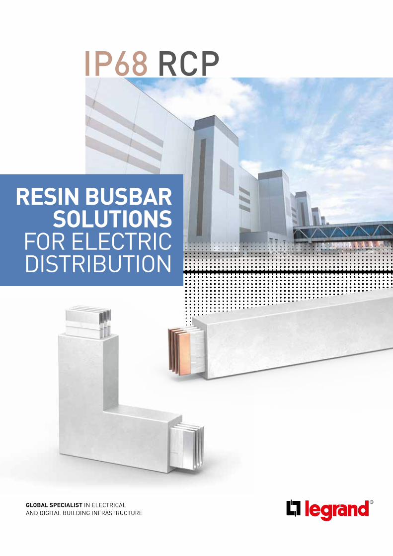
IP68 RCP GLOBAL SPECIALIST IN ELECTRICAL AND DIGITAL BUILDING INFRASTRUCTURE RESIN BUSBAR SOLUTIONS FOR ELECTRIC DISTRIBUTION
Transcript of IP68 RCP - Legrand · busbar IP68 RCP RCP IP68 RESIN BUSBAR New resin busbar RCP with range from...
IP68 RCP
GLOBAL SPECIALIST IN ELECTRICALAND DIGITAL BUILDING INFRASTRUCTURE
RESIN BUSBAR SOLUTIONS
FOR ELECTRIC DISTRIBUTION
2 RCP IP68 IN RESIN
busbar
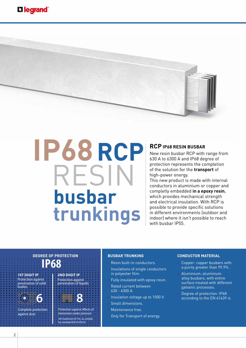
IP68 RCP RCP IP68 RESIN BUSBARNew resin busbar RCP with range from 630 A to 6300 A and IP68 degree of protection represents the completion of the solution for the transport of high-power energy. This new product is made with internal conductors in aluminium or copper and completly embedded in a epoxy resin, which provides mechanical strength and electrical insulation. With RCP is possible to provide specific solutions in different environments (outdoor and indoor) where it isn't possible to reach with busbar IP55.
RESIN
BUSBAR TRUNKING
■ Resin built-in conductors.
■ Insulations of single conductors in polyester film.
■ Fully insulated with epoxy resin.
■ Rated current between 630 - 6300 A.
■ Insulation voltage up to 1000 V.
■ Small dimensions.
■ Maintenance free.
■ Only for Transport of energy.
CONDUCTOR MATERIAL
■ Copper: copper busbars with a purity greater than 99.9% .
■ Aluminium: aluminium alloy busbars, with entire surface treated with different galvanic processes.
■ Degree of protection: IP68 according to the EN 61439-6.
trunkings
IP68
Complete protection against dust
Protection against effects of immersion under pressure
s52/06/95F
6 8m
s52/14/95F
DEGREE OF PROTECTION
1ST DIGIT IP Protection against penetration of solid bodies
2ND DIGIT IP Protection against penetration of liquids
(At maximum of 1m, as comply by standard EN 61439-6)

3RCP IP68 IN RESIN
A SOLUTION ADAPTS TO INDOOR AND OUTDOOR INSTALLATIONSThe RPC IP68 resin busbar trunking system is asolution mainly for outdoor in extreme conditions such as humidity, corrosion or saline mist environments and temporary immersion risks.
The typical applications of IP68 busbar trunkings are:
■ outdoor (in different extreme conditions).
■ industrial plants.
■ petrochemical plants.
■ chemical plants (*).
■ in areas with risk of flooding.
(*) attention at chemical components which are not compatible with the busbar’s resin (look the table on page 14).
Typical applications
4 RCP IP68 IN RESIN
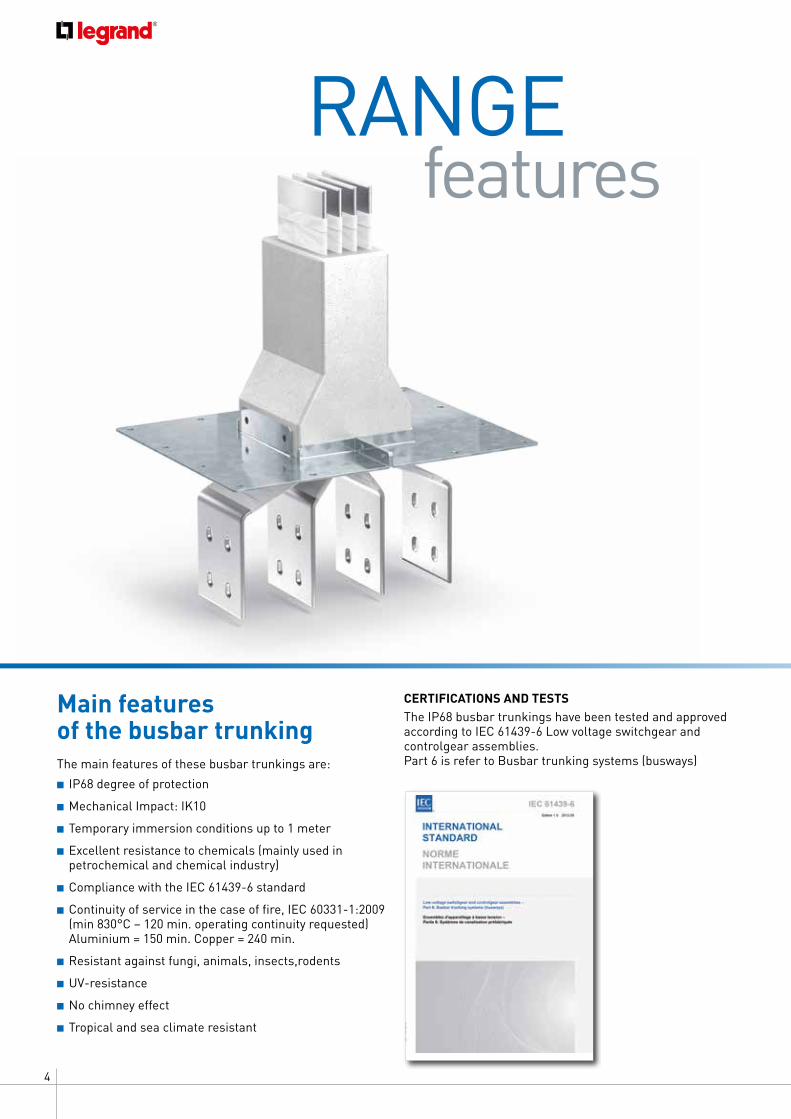
CERTIFICATIONS AND TESTSThe IP68 busbar trunkings have been tested and approved according to IEC 61439-6 Low voltage switchgear and controlgear assemblies. Part 6 is refer to Busbar trunking systems (busways)
Main features of the busbar trunkingThe main features of these busbar trunkings are:■ IP68 degree of protection
■ Mechanical Impact: IK10
■ Temporary immersion conditions up to 1 meter
■ Excellent resistance to chemicals (mainly used in petrochemical and chemical industry)
■ Compliance with the IEC 61439-6 standard
■ Continuity of service in the case of fire, IEC 60331-1:2009 (min 830°C – 120 min. operating continuity requested) Aluminium = 150 min. Copper = 240 min.
■ Resistant against fungi, animals, insects,rodents
■ UV-resistance
■ No chimney effect
■ Tropical and sea climate resistant
features RANGE
5RCP IP68 IN RESIN
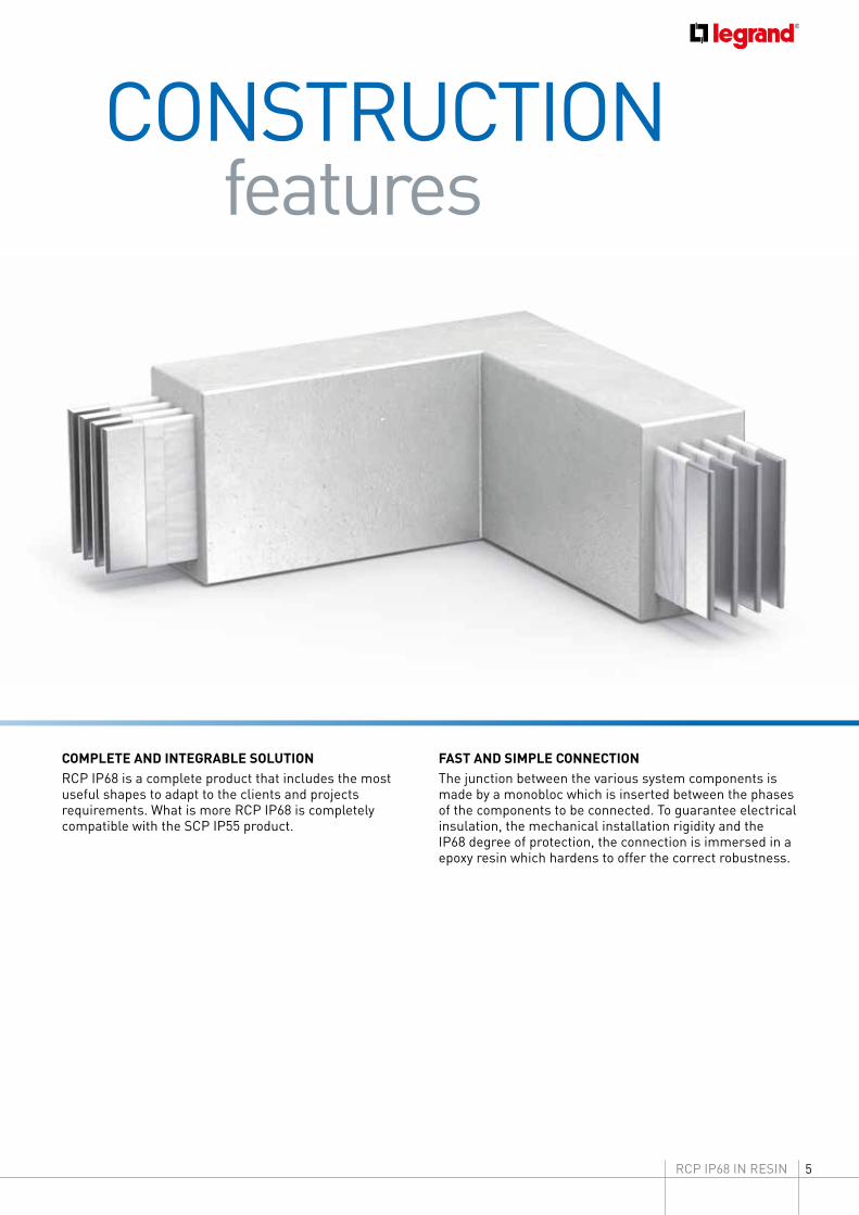
COMPLETE AND INTEGRABLE SOLUTIONRCP IP68 is a complete product that includes the most useful shapes to adapt to the clients and projects requirements. What is more RCP IP68 is completely compatible with the SCP IP55 product.
FAST AND SIMPLE CONNECTIONThe junction between the various system components is made by a monobloc which is inserted between the phases of the components to be connected. To guarantee electrical insulation, the mechanical installation rigidity and the IP68 degree of protection, the connection is immersed in a epoxy resin which hardens to offer the correct robustness.
features CONSTRUCTION
6 RCP IP68 IN RESIN
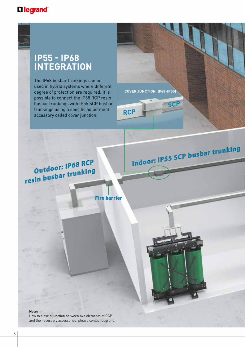
IP55 - IP68 INTEGRATIONThe IP68 busbar trunkings can be used in hybrid systems where different degree of protection are required. It is possible to connect the IP68 RCP resin busbar trunkings with IP55 SCP busbar trunkings using a specific adjustment accessory called cover junction. RCP
SCP
COVER JUNCTION (IP68-IP55)
Fire barrier
Note:How to close a junction between two elements of RCP and the necessary accessories, please contact Legrand.
7RCP IP68 IN RESIN
8 RCP IP68 IN RESIN
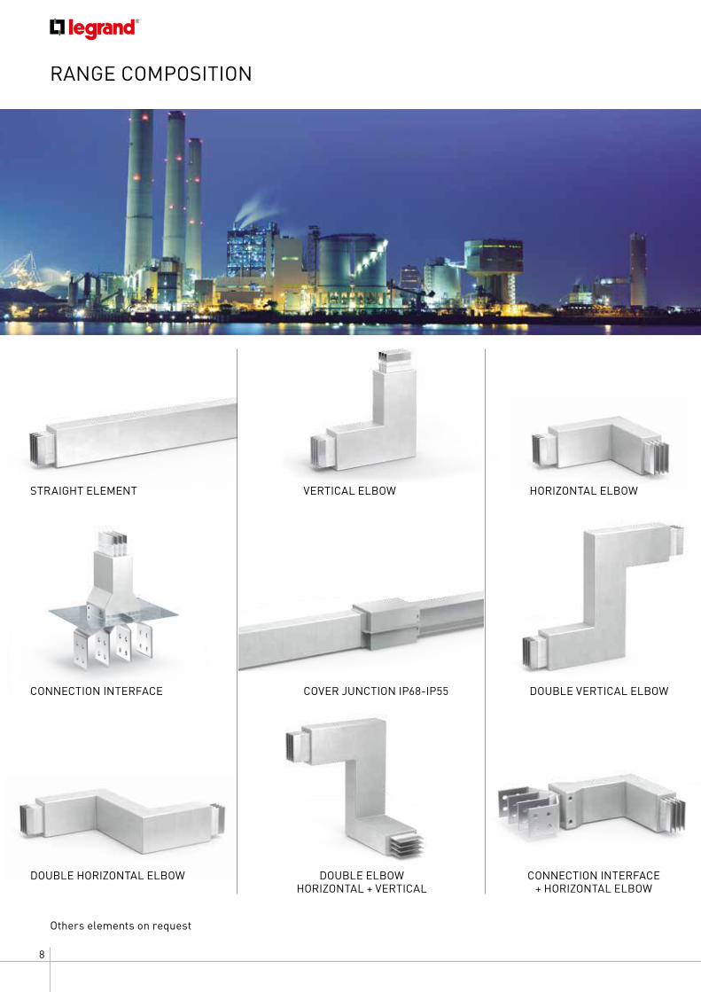
RANGE COMPOSITION
Others elements on request
DOUBLE VERTICAL ELBOWCOVER JUNCTION IP68-IP55
CONNECTION INTERFACE + HORIZONTAL ELBOW
STRAIGHT ELEMENT VERTICAL ELBOW
DOUBLE ELBOW HORIZONTAL + VERTICAL
HORIZONTAL ELBOW
DOUBLE HORIZONTAL ELBOW
CONNECTION INTERFACE
9RCP IP68 IN RESIN
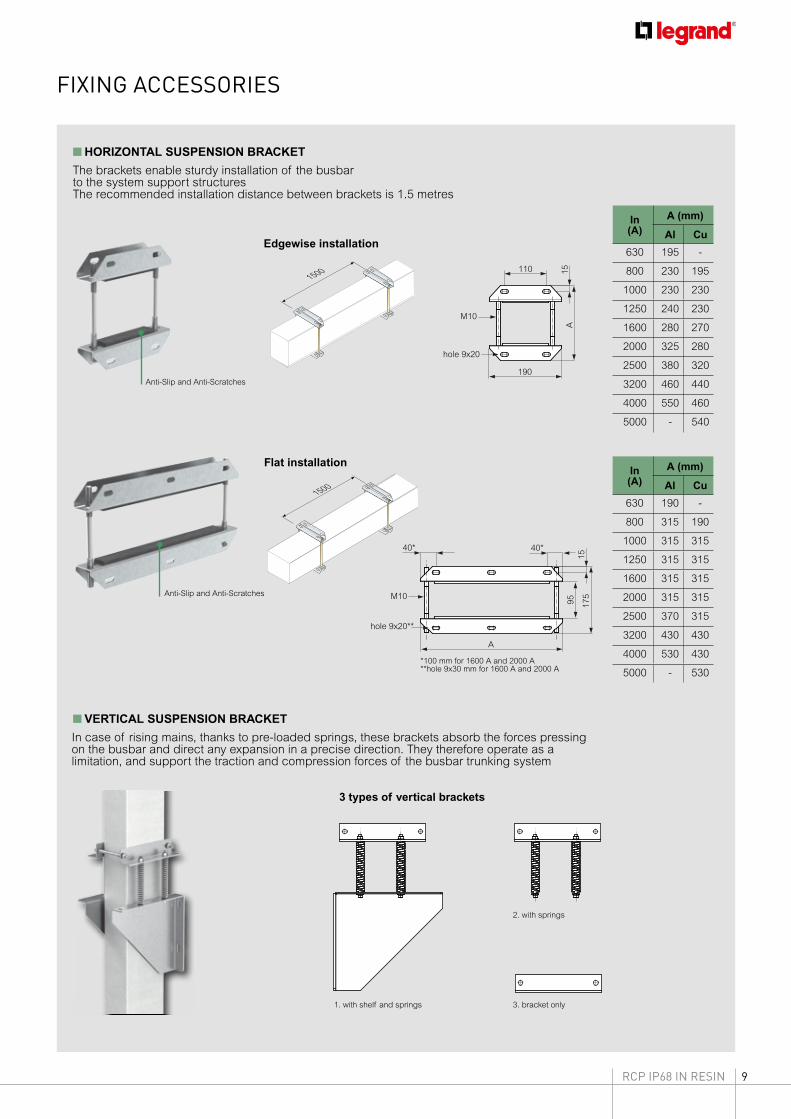
FIXING ACCESSORIES
■ HORIZONTAL SUSPENSION BRACKET
Edgewise installation
In(A)
A (mm)
Al Cu
630 195 -
800 230 195
1000 230 230
1250 240 230
1600 280 270
2000 325 280
2500 380 320
3200 460 440
4000 550 460
5000 - 540
In(A)
A (mm)
Al Cu
630 190 -
800 315 190
1000 315 315
1250 315 315
1600 315 315
2000 315 315
2500 370 315
3200 430 430
4000 530 430
5000 - 530
The brackets enable sturdy installation of the busbar to the system support structuresThe recommended installation distance between brackets is 1.5 metres
*100 mm for 1600 A and 2000 A**hole 9x30 mm for 1600 A and 2000 A
■ VERTICAL SUSPENSION BRACKET
In case of rising mains, thanks to pre-loaded springs, these brackets absorb the forces pressing on the busbar and direct any expansion in a precise direction. They therefore operate as a limitation, and support the traction and compression forces of the busbar trunking system
3 types of vertical brackets
1. with shelf and springs
2. with springs
3. bracket only
1500
190
11040* 40*
M10
hole 9x20 hole 9x20**
A
15A M10
1595 17
5
190
11040* 40*
M10
hole 9x20 hole 9x20**
A
15A M10
1595 17
5
Anti-Slip and Anti-Scratches
Anti-Slip and Anti-Scratches
1500
Flat installation
10 RCP IP68 IN RESIN
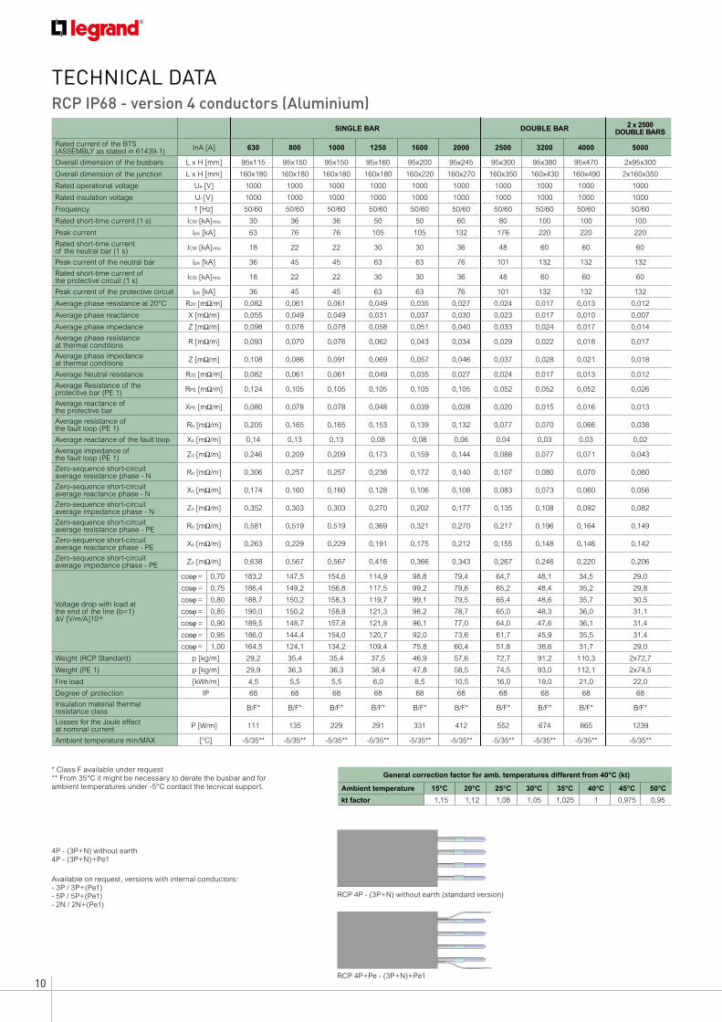
TECHNICAL DATA
SINGLE BAR DOUBLE BAR 2 x 2500 DOUBLE BARS
Rated current of the BTS(ASSEMBLY as stated in 61439-1) InA [A] 630 800 1000 1250 1600 2000 2500 3200 4000 5000
Overall dimension of the busbars L x H [mm] 95x115 95x150 95x150 95x160 95x200 95x245 95x300 95x380 95x470 2x95x300
Overall dimension of the junction L x H [mm] 160x180 160x180 160x180 160x180 160x220 160x270 160x350 160x430 160x490 2x160x350
Rated operational voltage Ue [V] 1000 1000 1000 1000 1000 1000 1000 1000 1000 1000
Rated insulation voltage Ui [V] 1000 1000 1000 1000 1000 1000 1000 1000 1000 1000
Frequency f [Hz] 50/60 50/60 50/60 50/60 50/60 50/60 50/60 50/60 50/60 50/60
Rated short-time current (1 s) ICW [kA]rms 30 36 36 50 50 60 80 100 100 100
Peak current Ipk [kA] 63 76 76 105 105 132 176 220 220 220
Rated short-time current of the neutral bar (1 s) ICW [kA]rms 18 22 22 30 30 36 48 60 60 60
Peak current of the neutral bar Ipk [kA] 36 45 45 63 63 76 101 132 132 132
Rated short-time current of the protective circuit (1 s) ICW [kA]rms 18 22 22 30 30 36 48 60 60 60
Peak current of the protective circuit Ipk [kA] 36 45 45 63 63 76 101 132 132 132
Average phase resistance at 20°C R20 [mΩ/m] 0,082 0,061 0,061 0,049 0,035 0,027 0,024 0,017 0,013 0,012
Average phase reactance X [mΩ/m] 0,055 0,049 0,049 0,031 0,037 0,030 0,023 0,017 0,010 0,007
Average phase impedance Z [mΩ/m] 0,098 0,078 0,078 0,058 0,051 0,040 0,033 0,024 0,017 0,014
Average phase resistance at thermal conditions R [mΩ/m] 0,093 0,070 0,076 0,062 0,043 0,034 0,029 0,022 0,018 0,017
Average phase impedance at thermal conditions Z [mΩ/m] 0,108 0,086 0,091 0,069 0,057 0,046 0,037 0,028 0,021 0,018
Average Neutral resistance R20 [mΩ/m] 0,082 0,061 0,061 0,049 0,035 0,027 0,024 0,017 0,013 0,012
Average Resistance of the protective bar (PE 1) RPE [mΩ/m] 0,124 0,105 0,105 0,105 0,105 0,105 0,052 0,052 0,052 0,026
Average reactance of the protective bar XPE [mΩ/m] 0,080 0,078 0,078 0,048 0,039 0,028 0,020 0,015 0,016 0,013
Average resistance of the fault loop (PE 1) Ro [mΩ/m] 0,205 0,165 0,165 0,153 0,139 0,132 0,077 0,070 0,066 0,038
Average reactance of the fault loop Xo [mΩ/m] 0,14 0,13 0,13 0,08 0,08 0,06 0,04 0,03 0,03 0,02
Average impedance of the fault loop (PE 1) Zo [mΩ/m] 0,246 0,209 0,209 0,173 0,159 0,144 0,088 0,077 0,071 0,043
Zero-sequence short-circuit average resistance phase - N Ro [mΩ/m] 0,306 0,257 0,257 0,238 0,172 0,140 0,107 0,080 0,070 0,060
Zero-sequence short-circuit average reactance phase - N Xo [mΩ/m] 0,174 0,160 0,160 0,128 0,106 0,108 0,083 0,073 0,060 0,056
Zero-sequence short-circuit average impedance phase - N Zo [mΩ/m] 0,352 0,303 0,303 0,270 0,202 0,177 0,135 0,108 0,092 0,082
Zero-sequence short-circuit average resistance phase - PE Ro [mΩ/m] 0,581 0,519 0,519 0,369 0,321 0,270 0,217 0,196 0,164 0,149
Zero-sequence short-circuit average reactance phase - PE Xo [mΩ/m] 0,263 0,229 0,229 0,191 0,175 0,212 0,155 0,148 0,146 0,142
Zero-sequence short-circuit average impedance phase - PE Zo [mΩ/m] 0,638 0,567 0,567 0,416 0,366 0,343 0,267 0,246 0,220 0,206
Voltage drop with load at the end of the line (b=1)ΔV [V/m/A]10-6
cosϕ = 0,70 183,2 147,5 154,6 114,9 98,8 79,4 64,7 48,1 34,5 29,0
cosϕ = 0,75 186,4 149,2 156,8 117,5 99,2 79,6 65,2 48,4 35,2 29,8
cosϕ = 0,80 188,7 150,2 158,3 119,7 99,1 79,5 65,4 48,6 35,7 30,5
cosϕ = 0,85 190,0 150,2 158,8 121,3 98,2 78,7 65,0 48,3 36,0 31,1
cosϕ = 0,90 189,5 148,7 157,8 121,8 96,1 77,0 64,0 47,6 36,1 31,4
cosϕ = 0,95 186,0 144,4 154,0 120,7 92,0 73,6 61,7 45,9 35,5 31,4
cosϕ = 1,00 164,5 124,1 134,2 109,4 75,8 60,4 51,8 38,6 31,7 29,0
Weight (RCP Standard) p [kg/m] 29,2 35,4 35,4 37,5 46,9 57,6 72,7 91,2 110,3 2x72,7
Weight (PE 1) p [kg/m] 29,9 36,3 36,3 38,4 47,8 58,5 74,5 93,0 112,1 2x74,5
Fire load [kWh/m] 4,5 5,5 5,5 6,0 8,5 10,5 16,0 19,0 21,0 22,0
Degree of protection IP 68 68 68 68 68 68 68 68 68 68
Insulation material thermal resistance class B/F* B/F* B/F* B/F* B/F* B/F* B/F* B/F* B/F* B/F*
Losses for the Joule effect at nominal current P [W/m] 111 135 229 291 331 412 552 674 865 1239
Ambient temperature min/MAX [°C] -5/35** -5/35** -5/35** -5/35** -5/35** -5/35** -5/35** -5/35** -5/35** -5/35**
General correction factor for amb. temperatures different from 40°C (kt)
Ambient temperature 15°C 20°C 25°C 30°C 35°C 40°C 45°C 50°C
kt factor 1,15 1,12 1,08 1,05 1,025 1 0,975 0,95
RCP IP68 - version 4 conductors (Aluminium)
* Class F available under request** From 35°C it might be necessary to derate the busbar and for ambient temperatures under -5°C contact the tecnical support.
4P - (3P+N) without earth4P - (3P+N)+Pe1
Available on request, versions with internal conductors:- 3P / 3P+(Pe1) - 5P / 5P+(Pe1)- 2N / 2N+(Pe1)
RCP STANDARD VERSION
RCP PE=1 VERSION
RCP STANDARD VERSION
RCP PE=1 VERSION
RCP 4P - (3P+N) without earth (standard version)
RCP 4P+Pe - (3P+N)+Pe1
11RCP IP68 IN RESIN
General correction factor for amb. temperatures different from 40°C (kt)
Ambient temperature 15°C 20°C 25°C 30°C 35°C 40°C 45°C 50°C
kt factor 1,15 1,12 1,08 1,05 1,025 1 0,975 0,95
SINGLE BAR DOUBLE BAR 2 x 2500 DOUBLE BARS
Rated current In [A] 800 1000 1250 1600 2000 2500 3200 4000 5000 6300
Overall dimension of the busbars L x H [mm] 95x115 95x150 95x150 95x190 95x200 95x240 95x360 95x380 95x460 2x95x360
Overall dimension of the junction L x H [mm] 160x180 160x180 160x180 160x220 160x220 160x270 160x430 160x430 160x490 2x160x430
Rated operational voltage Ue [V] 1000 1000 1000 1000 1000 1000 1000 1000 1000 1000
Rated insulation voltage Ui [V] 1000 1000 1000 1000 1000 1000 1000 1000 1000 1000
Frequency f [Hz] 50/60 50/60 50/60 50/60 50/60 50/60 50/60 50/60 50/60 50/61
Rated short-time current (1 s) ICW [kA]rms 45 45 45 65 65 80 100 100 100 100
Peak current Ipk [kA] 95 95 95 143 143 176 220 220 220 220
Rated short-time current of the neutral bar (1 s) ICW [kA]rms 27 27 27 39 39 48 60 60 60 60
Peak current of the neutral bar Ipk [kA] 57 57 57 82 82 101 132 132 132 132
Rated short-time current of the protective circuit (1 s) ICW [kA]rms 27 27 27 39 39 48 60 60 60 60
Peak current of the protective circuit Ipk [kA] 57 57 57 82 82 101 132 132 132 132
Average phase resistance at 20°C R20 [mΩ/m] 0,040 0,031 0,031 0,023 0,018 0,014 0,011 0,009 0,007 0,006
Average phase reactance X [mΩ/m] 0,055 0,049 0,049 0,045 0,037 0,030 0,023 0,017 0,010 0,007
Average phase impedance Z [mΩ/m] 0,068 0,058 0,058 0,050 0,041 0,033 0,026 0,019 0,012 0,009
Average phase resistance at thermal conditions R [mΩ/m] 0,045 0,037 0,039 0,028 0,023 0,018 0,014 0,012 0,009 0,007
Average phase impedance at thermal conditions Z [mΩ/m] 0,071 0,061 0,063 0,053 0,044 0,035 0,027 0,021 0,013 0,010
Average Neutral resistance R20 [mΩ/m] 0,040 0,031 0,031 0,023 0,018 0,014 0,011 0,009 0,007 0,006
Average Resistance of theprotective bar (PE 1) RPE [mΩ/m] 0,124 0,105 0,105 0,105 0,105 0,105 0,052 0,052 0,052 0,026
Average reactance of the protective bar XPE [mΩ/m] 0,054 0,054 0,054 0,044 0,044 0,032 0,022 0,017 0,016 0,014
Average resistance of the fault loop (PE 1) Ro [mΩ/m] 0,163 0,136 0,136 0,127 0,123 0,119 0,064 0,062 0,059 0,032
Average reactance of the fault loop Xo [mΩ/m] 0,11 0,10 0,10 0,09 0,08 0,06 0,05 0,03 0,03 0,02
Average impedance of the fault loop (PE 1) Zo [mΩ/m] 0,196 0,170 0,170 0,155 0,148 0,134 0,078 0,070 0,065 0,038
Zero-sequence short-circuit average resistance phase - N Ro [mΩ/m] 0,170 0,155 0,155 0,115 0,120 0,098 0,083 0,071 0,062 0,054
Zero-sequence short-circuit average reactance phase - N Xo [mΩ/m] 0,159 0,151 0,151 0,114 0,098 0,065 0,056 0,055 0,042 0,038
Zero-sequence short-circuit average impedance phase - N Zo [mΩ/m] 0,233 0,216 0,216 0,162 0,155 0,118 0,100 0,090 0,075 0,066
Zero-sequence short-circuit average resistance phase - PE Ro [mΩ/m] 0,507 0,429 0,429 0,331 0,283 0,221 0,177 0,178 0,144 0,132
Zero-sequence short-circuit average reactance phase - PE Xo [mΩ/m] 0,201 0,177 0,177 0,143 0,150 0,124 0,111 0,094 0,086 0,075
Zero-sequence short-circuit average impedance phase - PE Zo [mΩ/m] 0,545 0,464 0,464 0,361 0,320 0,253 0,209 0,201 0,168 0,152
Voltage drop with load at the end of the line ΔV [V/m/A]10-6
cosϕ = 0,70 123,4 105,7 108,8 90,7 74,6 59,3 45,4 35,6 23,5 17,9
cosϕ = 0,75 122,4 104,5 107,8 89,1 73,3 58,2 44,5 35,1 23,3 17,9
cosϕ = 0,80 120,5 102,5 106,0 86,8 71,4 56,6 43,2 34,4 23,1 17,8
cosϕ = 0,85 117,4 99,5 103,3 83,6 68,8 54,4 41,5 33,3 22,6 17,6
cosϕ = 0,90 112,7 95,0 99,0 79,0 65,0 51,2 39,1 31,6 21,8 17,1
cosϕ = 0,95 104,9 87,7 92,0 71,9 59,2 46,4 35,4 29,0 20,4 16,3
cosϕ = 1,00 79,1 64,4 68,9 50,1 41,2 31,8 24,2 20,9 15,8 13,1
Weight (RCP Standard) p [kg/m] 41,1 50,4 50,4 65,1 71,4 89,0 127,0 141,0 173,6 2x127
Weight (PE 1) p [kg/m] 41,9 51,3 51,3 66,0 72,3 89,9 128,8 142,8 175,4 2x128,8
Fire load [kWh/m] 4,5 5,5 5,5 8,0 8,2 10,5 16,0 19,0 21,0 24,0
Degree of protection IP 68 68 68 68 68 68 68 68 68 68
Insulation material thermal resistance class B/F* B/F* B/F* B/F* B/F* B/F* B/F* B/F* B/F* B/F*
Losses for the Joule effect at nominal current P [W/m] 86 110 184 219 281 339 422 570 675 890
Ambient temperature min/MAX [°C] -5/35** -5/35** -5/35** -5/35** -5/35** -5/35** -5/35** -5/35** -5/35** -5/35**
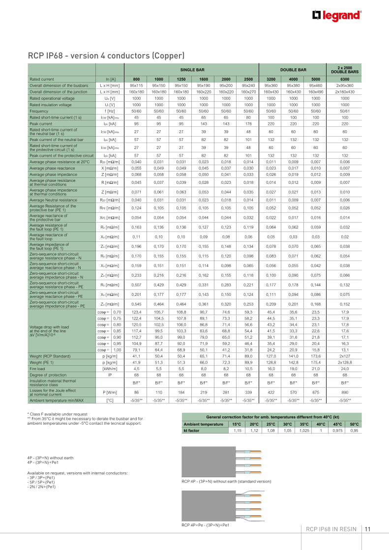
RCP IP68 - version 4 conductors (Copper)
4P - (3P+N) without earth4P - (3P+N)+Pe1
Available on request, versions with internal conductors:- 3P / 3P+(Pe1) - 5P / 5P+(Pe1)- 2N / 2N+(Pe1)
* Class F available under request** From 35°C it might be necessary to derate the busbar and for ambient temperatures under -5°C contact the tecnical support. RCP STANDARD VERSION
RCP PE=1 VERSION
RCP STANDARD VERSION
RCP PE=1 VERSION
RCP 4P - (3P+N) without earth (standard version)
RCP 4P+Pe - (3P+N)+Pe1
12 RCP IP68 IN RESIN
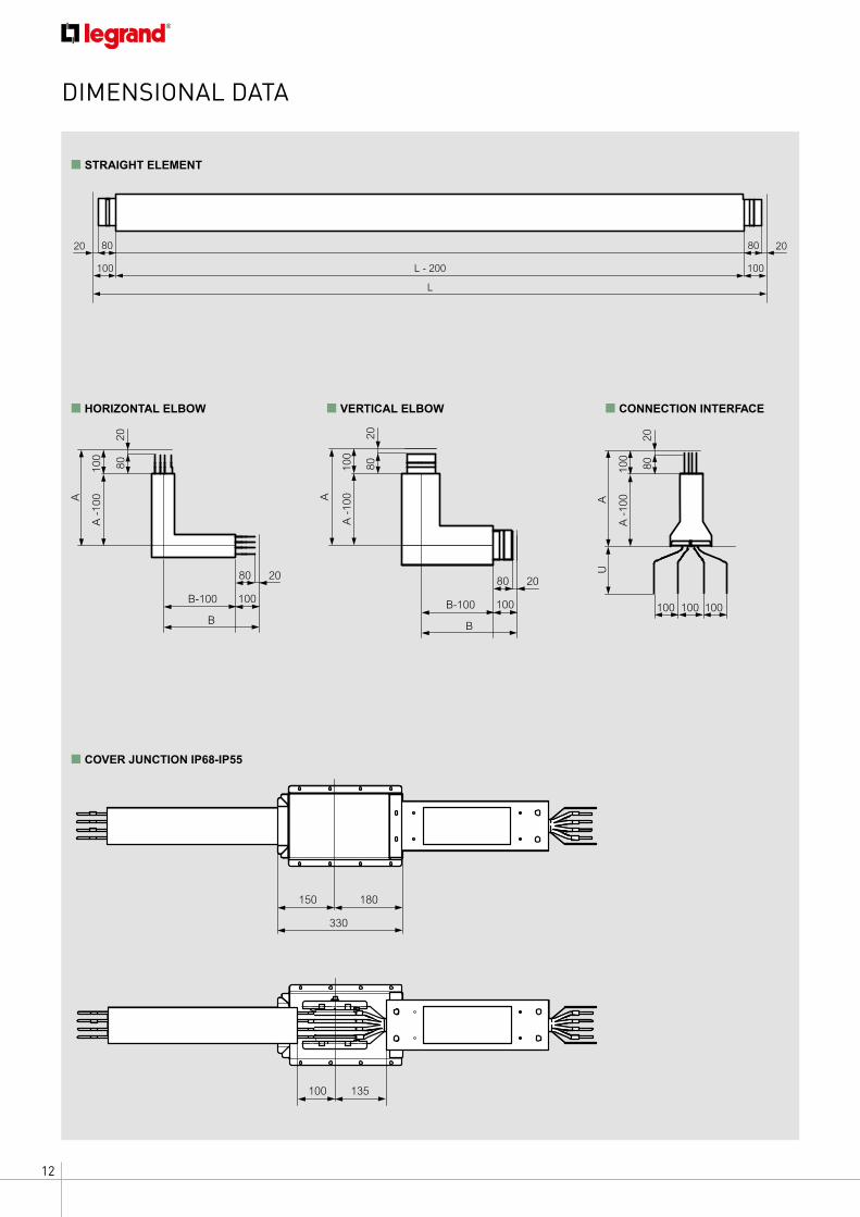
DIMENSIONAL DATA
L
L - 200100
8020 2080
100
208010
0A
-10
0A
B
20
100
80
B-100
B
20
100
80
B-100
2080
A
100
A -
100
2080
AU
100
A -
100
100 100 100
L
L - 200100
8020 2080
100
208010
0A
-10
0A
B
20
100
80
B-100
B
20
100
80
B-100
2080
A
100
A -
100
2080
AU
100
A -
100
100 100 100
L
L - 200100
8020 2080
100
208010
0A
-10
0A
B
20
100
80
B-100
B
20
100
80
B-100
2080
A
100
A -
100
2080
AU
100
A -
100
100 100 100
■ HORIZONTAL ELBOW ■ CONNECTION INTERFACE
100
80 20
B
B - 100
100
8020
A - 1
00
A
180
330
150
135100
100
80 20
B
B - 100
100
8020
A - 1
00
A
180
330
150
135100
■ COVER JUNCTION IP68-IP55
L
L - 200100
8020 2080
100
208010
0A
-10
0A
B
20
100
80
B-100
B
20
100
80
B-100
2080
A
100
A -
100
2080
AU
100
A -
100
100 100 100
■ VERTICAL ELBOW
■ STRAIGHT ELEMENT
13RCP IP68 IN RESIN
DIMENSIONAL DATA
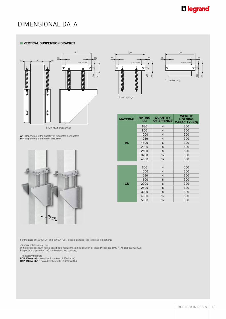
■ VERTICAL SUSPENSION BRACKET
FORI Ø11mm FORI Ø11mm FORI Ø11mmA*40
25
B** B**
2525
20 44
4025
20 44
B**
25 25
20 44
1. with shelf and springs
3. bracket only
100 mm
FORI Ø11mm FORI Ø11mm FORI Ø11mmA*40
25
B** B**
2525
20 44
4025
20 44
B**
25 25
20 44
MATERIAL RATING (A)
QUANTITY OF SPRINGS
WEIGHT HOLDING
CAPACITY (KG)
AL
630 4 300800 4 3001000 4 3001250 4 3001600 6 3002000 8 6002500 8 6003200 12 6004000 12 600
CU
800 4 3001000 4 3001250 4 3001600 6 3002000 6 3002500 8 6003200 8 6004000 12 6005000 12 600
For the case of 5000 A (Al) and 6300 A (Cu), please, consider the following indications:
- Vertical solution (only one)in the picture is shown how is possibile to realize the vertical solution for these two ranges 5000 A (Al) and 6300 A (Cu);Respect the distance of 100 mm between two busbars;
- Necessary bracketsRCP 5000 A (Al) = consider 2 brackets of 2500 A (Al)RCP 6300 A (Cu) = consider 2 brackets of 3200 A (Cu)
A*: Depending of the quantity of requested conductorsB**: Depending of the rating of busbar
2. with springs
14 RCP IP68 IN RESIN
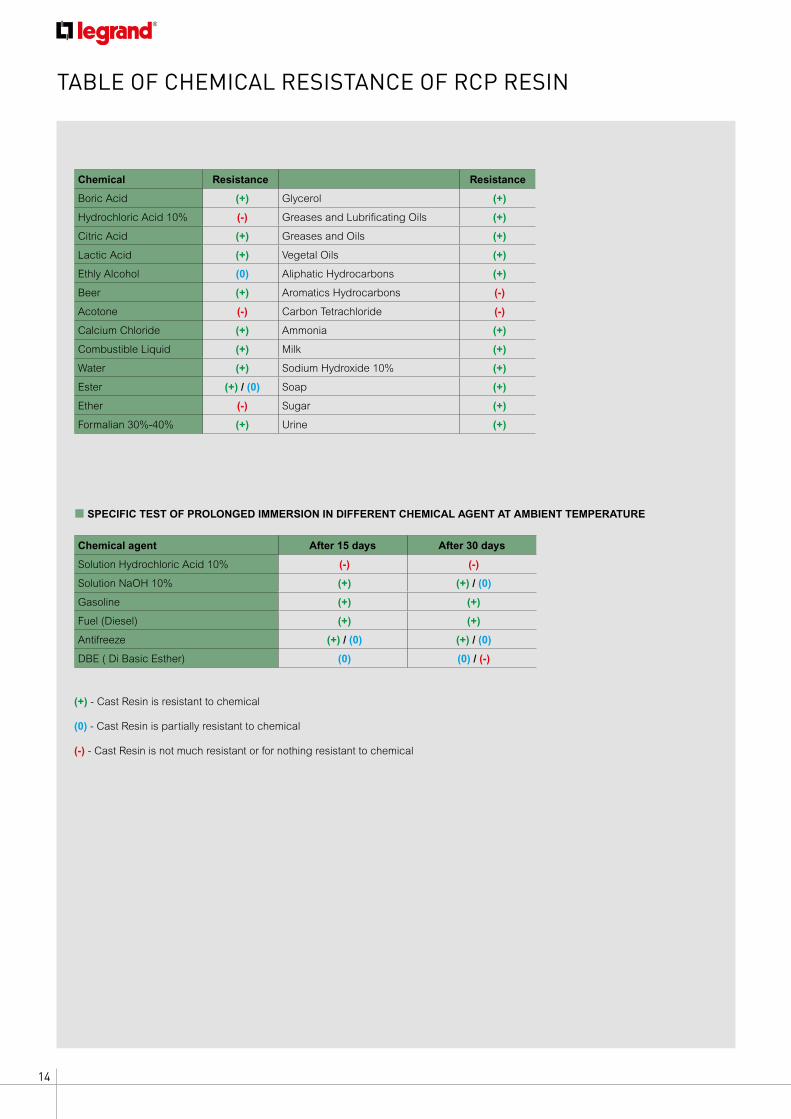
TABLE OF CHEMICAL RESISTANCE OF RCP RESIN
Chemical Resistance Resistance
Boric Acid (+) Glycerol (+)
Hydrochloric Acid 10% (-) Greases and Lubrificating Oils (+)
Citric Acid (+) Greases and Oils (+)
Lactic Acid (+) Vegetal Oils (+)
Ethly Alcohol (0) Aliphatic Hydrocarbons (+)
Beer (+) Aromatics Hydrocarbons (-)
Acotone (-) Carbon Tetrachloride (-)
Calcium Chloride (+) Ammonia (+)
Combustible Liquid (+) Milk (+)
Water (+) Sodium Hydroxide 10% (+)
Ester (+) / (0) Soap (+)
Ether (-) Sugar (+)
Formalian 30%-40% (+) Urine (+)
Chemical agent After 15 days After 30 days
Solution Hydrochloric Acid 10% (-) (-)
Solution NaOH 10% (+) (+) / (0)
Gasoline (+) (+)
Fuel (Diesel) (+) (+)
Antifreeze (+) / (0) (+) / (0)
DBE ( Di Basic Esther) (0) (0) / (-)
■ SPECIFIC TEST OF PROLONGED IMMERSION IN DIFFERENT CHEMICAL AGENT AT AMBIENT TEMPERATURE
(+) - Cast Resin is resistant to chemical
(0) - Cast Resin is partially resistant to chemical
(-) - Cast Resin is not much resistant or for nothing resistant to chemical

RCP IP68 IN RESIN

AD-E
XLG
/RCP
17C/
GB
- 0
1/20
17
Head officeand International Department87045 Limoges Cedex - FranceTel.: + 33 (0) 5 55 06 87 87Fax: + 33 (0) 5 55 06 74 55
FOLLOW US ALSO ON
www.legrand.com
www.youtube.com/legrand
twitter.com/@legrand