IP1733 - rev. 2004-06-07 - Garažo vartai, garažo vartų...
23
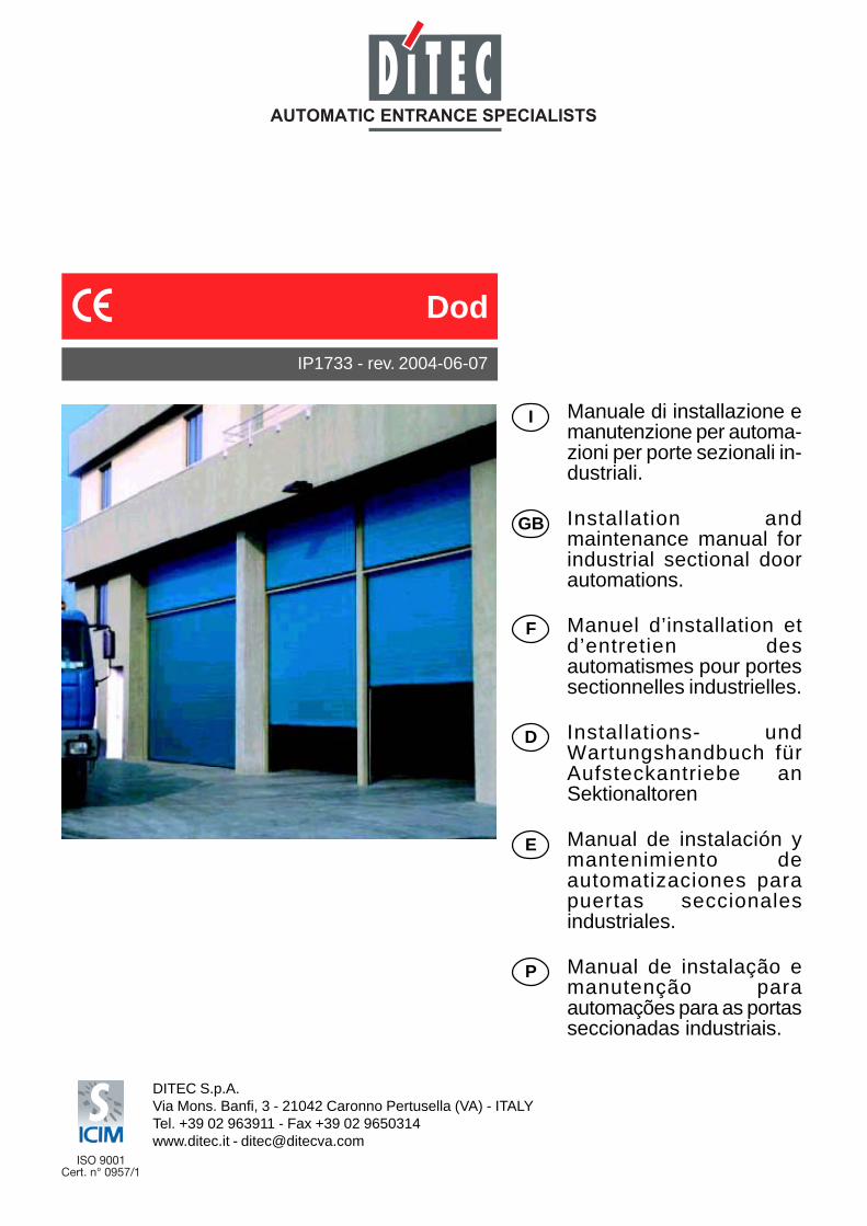
IP1733 - rev. 2004-06-07 I GB F D E P Manuale di installazione e manutenzione per automa- zioni per porte sezionali in- dustriali. Installation and maintenance manual for industrial sectional door automations. Manuel d’installation et d’entretien des automatismes pour portes sectionnelles industrielles. Installations- und Wartungshandbuch für Aufsteckantriebe an Sektionaltoren Manual de instalación y mantenimiento de automatizaciones para puertas seccionales industriales. Manual de instalação e manutenção para automações para as portas seccionadas industriais. DITEC S.p.A. Via Mons. Banfi, 3 - 21042 Caronno Pertusella (VA) - ITALY Tel. +39 02 963911 - Fax +39 02 9650314 www.ditec.it - [email protected] Dod
Transcript of IP1733 - rev. 2004-06-07 - Garažo vartai, garažo vartų...
IP1733 - rev. 2004-06-07
I
GB
F
D
E
P
Manuale di installazione emanutenzione per automa-zioni per porte sezionali in-dustriali.
Installation andmaintenance manual forindustrial sectional doorautomations.
Manuel d’installation etd’entretien desautomatismes pour portessectionnelles industrielles.
Installations- undWartungshandbuch fürAufsteckantriebe anSektionaltoren
Manual de instalación ymantenimiento deautomatizaciones parapuertas seccionalesindustriales.
Manual de instalação emanutenção paraautomações para as portasseccionadas industriais.
DITEC S.p.A.Via Mons. Banfi, 3 - 21042 Caronno Pertusella (VA) - ITALYTel. +39 02 963911 - Fax +39 02 9650314www.ditec.it - [email protected]
Dod

3 DITEC S.P.A - IP1733 - DOD
GENERAL SAFETY PRECAUTIONSThis installation manual is intended for professionallycompetent personnel only.
Installation, electrical connections and adjustments must beperformed in accordance with Good Working Methods and incompliance with applicable regulations.Before installing the product, carefully read the instructions. Badinstallation could be hazardous.The packaging materials (plastic, polystyrene, etc.) should notbe discarded in the environment or left within reach of children,as these are a potential source of hazard.Before installing the product, make sure it is in perfect condi-tion.Do not install the product in an explosive environment and at-mosphere: gas or inflammable fumes are a serious hazard risk.Before installing the motors, make all structural changes relat-ing to safety clearances and protection or segregation of allareas where there is risk of being crushed, cut or dragged, anddanger areas in general.Make sure the existing structure is up to standard in terms ofstrength and stability.The motor manufacturer is not responsible for failure to useGood Working Methods in building the frames to be motorisedor for any deformation occurring during use.The safety devices (photocells, safety edges, emergency stops,etc.) must be installed taking into account: applicable laws anddirectives, Good Working Methods, installation premises, sys-tem operating logic and the forces developed by the motoriseddoor or gate.The safety devices must protect any areas where the risk existsof being crushed, cut or gragged, or where there are any otherrisks generated by the motorised door or gate. Apply hazardarea notices required by applicable regulations.Each installation must clearly show the identification details ofthe motorised door or gate.
Before making power connections, make sure the platedetails correspond to those of the power mains.
Fit an omnipolar disconnection switch with a contact openinggap of at least 3 mm. Make sure an adequate residual currentcircuit breaker and overcurrent cutout are fitted upstream of theelectrical system.When necessary, connect the motorised door or gate to a reli-able earth system made in accordance with applicable safetyregulations. During installation, maintenance and repair, inter-rupt the power supply before opening the lid to access the elec-trical parts.
To handle electronic parts, wear earthed antistatic con-ductive bracelets.
The motor manufacturer declines all responsibility in the eventof component parts being fitted that are not compatible with thesafe an correct operation.For repairs or replacements of products only original spare partsmust be used.The installer shall provide all information relating to automatic,manual and emergency operation of the motorised door or gate,and provide the user with operating instructions.
MACHINERY DIRECTIVEPursuant to Machinery Directive (98/37/EC) the installer whomotorises a door or gate has the same obligations as the manu-facturer of machinery and as such must:- prepare the technical file which must contain the documents
indicated in Annex V of the Machinery Directive; (The techni-cal file must be kept and placed at the disposal of competentnational authorities for at least ten years from the date ofmanufacture of the motorised door);
- draft the EC declaration of conformity in accordance with An-nex II-A of the Machinery Directive and deliver it to the cus-tomer;
- affix the CE marking on the power operated door in accord-ance with point 1.7.3 of Annex I of the Machinery Directive.
For more information consult the “Technical Manual Guidelines”available on Internet at the following address: www.ditec.it
APPLICATIONSService class: 4 (minimum 100 cycles a day for 10 years or200 cycles a day for 5 years)Use: INTENSIVE (For vehicle or pedestrian accesses to largecondominiums, industrial or commercial complexes and parkinglots with very frequent use).- The operating performance specifications refer to the
recommended weight (about 2/3 of maximum allowedweight). Use with maximum allowed weight could reducethe above performance specifications in tecnhical data.
- The service class, operating times and number of consecu-tive cycles are merely approximate. These have beenstatistically determined in average conditions of use and arenot certain for each single case. They refer to the periodwhen the product operates without the need for specialmaintenance.
- Each automatic entrance features variable factors such as:friction, balancing and environmental conditions that cansubstantially change both the duration and operating qualityof the automatic entrance or part of its components (includingautomatic system). It is up to the installer to adopt adequatesafety coefficients for each single installation.
DECLARATION BY THE MANUFACTURER(Directive 98/37/EC, Annex II, sub B)Manufacturer: DITEC S.p.A.Address: via Mons. Banfi, 3-21042 Caronno P.lla
(VA) - ITALYHerewith declares that the electromechanical automatic sys-tem series DOD12-14-15- is intended to be incorpored into machinery or to be assem-
bled with other machinery to constitute machinery converedby Directive 98/37/EC;
- is in conformity with the provisions of the following other EECdirectives: Electromagnetic Compatibility Directive 89/336/EEC;Low Voltage Directive 73/23/EEC; and furthermore declaresthat it is not allowed to put the machinery into service until themachinery into which it is to be incorporated or of which it isto be a component has been found and declared to be inconformity with the provisions of Directive 98/37/EC and withnational implementing legislation.
Caronno Pertusella, 18-11-2003Fermo Bressanini (Chairman)
GB
8DITEC S.P.A - IP1733 - DOD
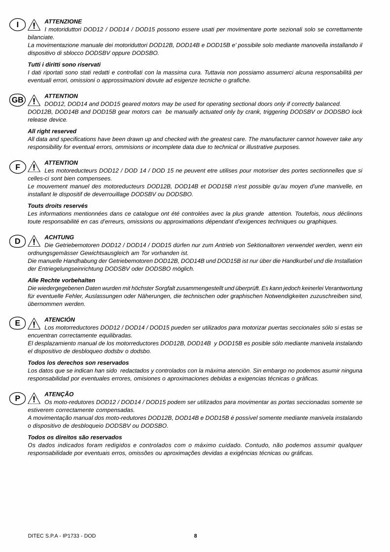
ATTENZIONEI motoriduttori DOD12 / DOD14 / DOD15 possono essere usati per movimentare porte sezionali solo se correttamente
bilanciate.La movimentazione manuale dei motoriduttori DOD12B, DOD14B e DOD15B e’ possibile solo mediante manovella installando ildispositivo di sblocco DODSBV oppure DODSBO.
Tutti i diritti sono riservatiI dati riportati sono stati redatti e controllati con la massima cura. Tuttavia non possiamo assumerci alcuna responsabilità pereventuali errori, omissioni o approssimazioni dovute ad esigenze tecniche o grafiche.
ATTENTIONDOD12, DOD14 and DOD15 geared motors may be used for operating sectional doors only if correctly balanced.
DOD12B, DOD14B and DOD15B gear motors can be manually actuated only by crank, triggering DODSBV or DODSBO lockrelease device.
All right reservedAll data and specifications have been drawn up and checked with the greatest care. The manufacturer cannot however take anyresponsibility for eventual errors, ommisions or incomplete data due to technical or illustrative purposes.
ATTENTIONLes motoreducteurs DOD12 / DOD 14 / DOD 15 ne peuvent etre utilises pour motoriser des portes sectionnelles que si
celles-ci sont bien compensees.Le mouvement manuel des motoreducteurs DOD12B, DOD14B et DOD15B n’est possible qu’au moyen d’une manivelle, eninstallant le dispositif de deverrouillage DODSBV ou DODSBO.
Touts droits reservésLes informations mentionnées dans ce catalogue ont été controlées avec la plus grande attention. Toutefois, nous déclinonstoute responsabilité en cas d’erreurs, omissions ou approximations dépendant d’exigences techniques ou graphiques.
ACHTUNGDie Getriebemotoren DOD12 / DOD14 / DOD15 dürfen nur zum Antrieb von Sektionaltoren verwendet werden, wenn ein
ordnungsgemässer Gewichtsausgleich am Tor vorhanden ist.Die manuelle Handhabung der Getriebemotoren DOD12B, DOD14B und DOD15B ist nur über die Handkurbel und die Installationder Entriegelungseinrichtung DODSBV oder DODSBO möglich.
Alle Rechte vorbehaltenDie wiedergegebenen Daten wurden mit höchster Sorgfalt zusammengestellt und überprüft. Es kann jedoch keinerlei Verantwortungfür eventuelle Fehler, Auslassungen oder Näherungen, die technischen oder graphischen Notwendigkeiten zuzuschreiben sind,übernommen werden.
ATENCIÓNLos motorreductores DOD12 / DOD14 / DOD15 pueden ser utilizados para motorizar puertas seccionales sólo si estas se
encuentran correctamente equilibradas.El desplazamiento manual de los motorreductores DOD12B, DOD14B y DOD15B es posible sólo mediante manivela instalandoel dispositivo de desbloqueo dodsbv o dodsbo.
Todos los derechos son reservadosLos datos que se indican han sido redactados y controlados con la màxima atenciòn. Sin embargo no podemos asumir ningunaresponsabilidad por eventuales errores, omisiones o aproximaciones debidas a exigencias técnicas o gràficas.
ATENÇÃOOs moto-redutores DOD12 / DOD14 / DOD15 podem ser utilizados para movimentar as portas seccionadas somente se
estiverem correctamente compensadas.A movimentação manual dos moto-redutores DOD12B, DOD14B e DOD15B é possível somente mediante manivela instalandoo dispositivo de desbloqueio DODSBV ou DODSBO.
Todos os direitos são reservadosOs dados indicados foram redigidos e controlados com o máximo cuidado. Contudo, não podemos assumir qualquerresponsabilidade por eventuais erros, omissões ou aproximações devidas a exigências técnicas ou gráficas.
I
GB
F
D
E
P

9 DITEC S.P.A - IP1733 - DOD
DAT
ITE
CN
ICI
Alim
enta
zione
Asso
rbim
ento
Pote
nza
mot
ore
Cop
pia
Giri
alb
ero
ditr
asm
issi
one
Cla
sse
di s
ervi
zio
Num
ero
min
imo
cicl
i con
secu
tivi
Inte
rmitt
enza
Gra
do d
ipr
otez
ione
Peso
Tem
pera
tura
Qua
dro
elet
tric
o
TEC
HN
ICA
LD
ATA
Pow
er s
uppl
y
Abs
orpt
ion
Mot
or p
ower
Par
max
imo
Rev
olut
ion
tran
smis
sion
sha
ft
Serv
ice
clas
s
Min
. num
ber
of c
onse
cutiv
ecy
cles
Inte
rmitt
ence
Deg
ree
ofpr
otec
tion
Wei
ght
Tem
pera
ture
Con
trol
pane
l
DO
NN
EES
TEC
HN
IQU
ES
Alim
enta
tion
Abs
orpt
ion
Puis
sanc
e m
oteu
r
Cou
ple
mot
ored
ucte
ur
Tour
s ar
bre
detr
ansm
issi
on
Cla
sse
de s
ervi
ce
Nom
. min
. de
cycl
esco
nséc
utifs
Inte
rmitt
ence
Deg
ré d
epr
otec
tion
Poid
s
Tem
pera
ture
Arm
oire
de
com
man
de
TEC
HN
ISC
HE
DAT
EN
Span
nung
s-ve
rsor
gung
Stro
mau
fnah
me
Mot
oren
leis
tung
Dre
hmom
ent
Um
dreh
unge
n de
rA
ntrie
bs-w
elle
Bet
riebs
klas
se
Höc
hsta
nzah
lau
fein
ande
rfolg
ende
rZy
klen
Eins
chal
tdau
er
Schu
tzgr
ad
Gew
icht
Tem
pera
tur
Pass
ende
Steu
erun
g
DAT
OS
TEC
NIC
OS
Alim
enta
ciòn
Con
sum
o
Pote
ncia
mot
or
Par
max
imo
Vuel
ta a
rbol
de
tra
nsm
issi
òn
Cla
se d
e se
rvic
io
Núm
. mín
imo
deci
clos
cons
ecut
ivos
Inte
rmitt
enci
a
Gra
do d
epr
otec
ciòn
Peso
Tem
pera
tura
Tabl
ero
de m
ando
DA
DO
STE
CN
ICO
S
Alim
enta
ção
Abs
orçã
o
Potê
ncia
do
mot
or
Tom
ada
Rot
açõe
s da
árvo
re d
etr
ansm
issã
o
Cla
sse
de s
ervi
ço
Núm
. mín
. de
cicl
osco
nsec
utiv
os
Inte
rmitê
ncia
Gra
u de
prot
eção
Peso
Tem
pera
tura
Qua
dro
elec
trón
ico
DO
D12
DO
D12
B
230
V~
50 H
z
3 A
350
W
45 N
m
32R
PM
4 - I
NTE
NS
IVE
50
S2=
30m
inS
3=50
%
IP54
15 K
g
-20°
C /
+55°
C
E1F
LOG
ICA
21F
DO
D14
DO
D14
B
230
V~
50 H
z
3 A
350
W
60 N
m
22 R
PM
4 - I
NTE
NS
IVE
50
S2=
30m
inS
3=50
%
IP54
15 K
g
-20°
C /
+55°
C
E1F
LOG
ICA
21F
DO
D15
DO
D15
B
400V
~ 50
Hz
1.2
A
450
W
65 N
m
32 R
PM
4 - I
NTE
NS
IVE
50
S2=
30m
inS
3=50
%
IP54
15 K
g
-20°
C /
+55°
C
LOG
ICTF

10DITEC S.P.A - IP1733 - DOD
ØN
DO
D12
DO
D14
DO
D15
ØN
DO
D12
DO
D14
DO
D15
DO
DT
DO
DC
30(Z
30)
CAT
1+C
ATG
Tipo
Type
DO
D15
DO
D12
DO
D12
DO
D14
Pig
none
Pini
on --
DO
DT
(Z24
)
DO
DT
(Z24
)
Cor
ona
Cro
wn
--
DO
DC
30(Z
30)
DO
DC
30(Z
30)
Rap
porto
di r
iduz
ione
Red
uctio
n ra
tio
1:1
1:1
1:1,
25
1:1,
25
Cop
pia
Torq
ueN
m 6545 56 75
Velo
cità
di r
otaz
ione
Rot
atin
g sp
eed
RPM 3232 25,6
17,6
Pule
ggia
avv
olgi
cavo
Doo
r cab
le p
ulle
yØ
mm
102
124
158
226
Ø 102
124
158
226
Ø 102
124
158
226
Ø 102
124
158
226
Ø
Veloc
ità d
ell’au
tom
azion
eSp
eed
of th
e do
orm
/s0,
170,
210,
260,
38=
Ø :
597
0,17
0,21
0,26
0,38
= Ø
: 59
7
0,14
0,17
0,21
0,30
= Ø
: 74
60,
090,
110,
150,
21=
Ø :
1085
Cor
sa m
axM
ax d
oor r
unm 8,
710
,613
,619
,4=
Ø :
11,6
6
8,7
10,6
13,6
19,4
= Ø
: 11
,66
7,0
8,5
10,8
15,5
= Ø
: 14
,57
7,0
8,5
10,8
15,5
= Ø
: 14
,57
Forz
a m
axM
ax fo
rce
N 706
581
456
319
= 72
.000
: Ø
1.02
083
965
846
0=
104.
000
: Ø
882
726
570
398
= 90
.000
: Ø
1.17
696
875
953
1=
120.
000
: Ø
DO
D15
DO
DT
(Z24
)D
OD
30(Z
30)
1:1,
2581
25,6
102
124
158
226
Ø
0,14
0,17
0,21
0,30
= Ø
: 74
6
7,0
8,5
10,8
15,5
= Ø
: 14
,57
1.27
51.
048
823
575
= 13
0.00
0 : Ø
DO
D14
--
1:1
6022
102
124
158
226
Ø
0,12
0,14
0,18
0,26
= Ø
: 86
8
8,7
10,6
13,6
19,4
= Ø
: 11
,66
941
774
608
425
= 96
.000
: Ø
Tipo
Type
Pig
none
Pini
onC
oron
aC
row
nR
appo
rto d
i rid
uzio
neR
educ
tion
ratio
Cop
pia
Torq
ueN
m
Velo
cità
di r
otaz
ione
Rot
atin
g sp
eed
RPM
Pule
ggia
avv
olgi
cavo
Doo
r cab
le p
ulle
yØ
mm
Velo
cità
dell’a
utom
azio
neSp
eed
of th
e do
orm
/s
Cor
sa m
axM
ax d
oor r
unm
Forz
a m
axM
ax fo
rce
N
ATTE
NZI
ON
E: P
er u
n co
rretto
funz
iona
men
to, s
i con
sigl
ia d
i muo
vere
l’au
tom
azio
ne a
d un
a ve
loci
tà in
ferio
re a
0,2
m/s
.W
ARN
ING
: for
cor
rect
ope
ratio
n w
e ad
vise
to m
ove
the
door
at a
spe
ed lo
wer
than
0.2
m/s
.AT
TEN
TIO
N :
Pour
un
bon
fonc
tionn
emen
t, il
est c
onse
illé d
e ré
gler
la v
itess
e du
mou
vem
ent d
e la
por
te à
moi
ns d
e 0,
2 m
/s.
ACH
TUN
G: F
ür e
inen
ein
wan
dfre
ien
Betri
eb e
mpf
iehl
t es
sich
, das
Tor
mit
eine
r Ges
chw
indi
gkei
t unt
er 0
,2 m
/s z
u be
weg
en.
ATEN
CIÓ
N: P
ara
un c
orre
cto
func
iona
mie
nto,
se
acon
seja
mov
er la
pue
rta a
una
vel
ocid
ad in
ferio
r a 0
,2 m
/s.
ATEN
ÇÃO
: Par
a um
func
iona
men
to c
orre
cto,
se
acon
selh
a de
mov
er a
por
ta c
om u
ma
velo
cida
de in
ferio
r a 0
,2 m
/s.
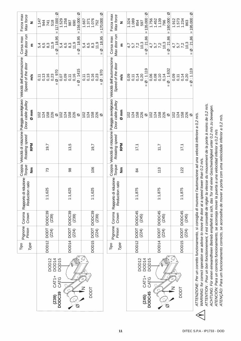
11 DITEC S.P.A - IP1733 - DOD
DO
D12
DO
D14
DO
DT
(Z24
)
DO
DT
(Z24
)
DO
DC
39(Z
39)
DO
DC
39(Z
39)
1:1,
625
1:1,
625
73 98
19,7
13,5
102
124
158
226
Ø 102
124
158
226
Ø
0,11
0,13
0,16
0,23
= Ø
: 97
00,
070,
090,
110,
16=
Ø :
1415
5,4
6,5
8,3
11,9
= Ø
: 18
,95
5,4
6,5
8,3
11,9
= Ø
: 18
,95
1.14
794
474
151
8=
117.
000
: Ø1.
529
1.25
898
769
0=
156.
000
: Ø
DO
D15
DO
DT
(Z24
)D
OD
C39
(Z39
)1:
1,62
510
619
,7
102
124
158
226
Ø
0,11
0,13
0,16
0,23
= Ø
: 97
0
5,4
6,5
8,3
11,9
= Ø
: 18
,95
1.66
71.
371
1.07
675
2=
170.
000
: Ø
ØN
DO
D12
DO
D14
DO
D15
DO
DT
DO
DC
39(Z
39)
CAT
1+C
ATG
Tipo
Type
Pig
none
Pini
onC
oron
aC
row
nR
appo
rto d
i rid
uzio
neR
educ
tion
ratio
Cop
pia
Torq
ueN
m
Velo
cità
di r
otaz
ione
Rot
atin
g sp
eed
RPM
Pule
ggia
avv
olgi
cavo
Doo
r cab
le p
ulle
yØ
mm
Velo
cità
dell’a
utom
azio
neSp
eed
of th
e do
orm
/s
Cor
sa m
axM
ax d
oor r
unm
Forz
a m
axM
ax fo
rce
N
DO
D12
DO
D14
DO
DT
(Z24
)
DO
DT
(Z24
)
DO
DC
45(Z
45)
DO
DC
45(Z
45)
1:1,
875
1:1,
875
84 113
17,1
11,7
102
124
158
226
Ø 102
124
158
226
Ø
0,09
0,11
0,14
0,20
= Ø
: 1.
119
0,06
0,08
0,10
0,14
= Ø
: 1.
632
4,7
5,7
7,2
10,3
= Ø
: 21
,86
4,7
5,7
7,2
10,3
= Ø
: 21
,86
1.32
41.
089
854
597
= 13
5.00
0 : Ø
1.75
61.
452
1.13
979
6=
180.
000
: Ø
DO
D15
DO
DT
(Z24
)D
OD
C45
(Z45
)1:
1,87
512
217
,1
102
124
158
226
Ø
0,09
0,11
0,14
0,20
= Ø
: 1.
119
4,7
5,7
7,2
10,3
= Ø
: 21
,86
1.91
21.
573
1.23
486
3=
195.
000
: Ø
ØN
DO
D12
DO
D14
DO
D15
DO
DT
DO
DC
45(Z
45)
CAT
1+C
ATG
Tipo
Type
Pig
none
Pini
onC
oron
aC
row
nR
appo
rto d
i rid
uzio
neR
educ
tion
ratio
Cop
pia
Torq
ueN
m
Velo
cità
di r
otaz
ione
Rot
atin
g sp
eed
RPM
Pule
ggia
avv
olgi
cavo
Doo
r cab
le p
ulle
yØ
mm
Velo
cità
dell’a
utom
azio
neSp
eed
of th
e do
orm
/s
Cor
sa m
axM
ax d
oor r
unm
Forz
a m
axM
ax fo
rce
N
ATTE
NZI
ON
E: P
er u
n co
rretto
funz
iona
men
to, s
i con
sigl
ia d
i muo
vere
l’au
tom
azio
ne a
d un
a ve
loci
tà in
ferio
re a
0,2
m/s
.W
ARN
ING
: for
cor
rect
ope
ratio
n w
e ad
vise
to m
ove
the
door
at a
spe
ed lo
wer
than
0.2
m/s
.AT
TEN
TIO
N :
Pour
un
bon
fonc
tionn
emen
t, il
est c
onse
illé d
e ré
gler
la v
itess
e du
mou
vem
ent d
e la
por
te à
moi
ns d
e 0,
2 m
/s.
ACH
TUN
G: F
ür e
inen
ein
wan
dfre
ien
Betri
eb e
mpf
iehl
t es
sich
, das
Tor
mit
eine
r Ges
chw
indi
gkei
t unt
er 0
,2 m
/s z
u be
weg
en.
ATEN
CIÓ
N: P
ara
un c
orre
cto
func
iona
mie
nto,
se
acon
seja
mov
er la
pue
rta a
una
vel
ocid
ad in
ferio
r a 0
,2 m
/sAT
ENÇ
ÃO: P
ara
um fu
ncio
nam
ento
cor
rect
o, s
e ac
onse
lha
de m
over
a p
orta
com
um
a ve
loci
dade
infe
rior a
0,2
m/s
.

12DITEC S.P.A - IP1733 - DOD
VIA M
ONS. BANFI,3
21042 CARONNO P.LLA (V
A)
ITALY
TEL.02/963911 FAX.02/9650314DIT
EC S
.p.A
.
DOOR TYPE
YEAR OF M
ANUFACTURE
VOLTAGE SUPPLY
SERIAL NUMBER
Made in
Italy
00000
00000000000
0000
000V
3x1.
5 m
m² (
DO
D12
-14)
LOGICA21FLOGICTFE1F
4x1.
5 m
m² (
DO
D15
)
MIN
=2,5
m
3x0.5 mm² (limitswitch)
4x1.5 mm² (motor)
DOD12- 14 -15
Unlockdevice
Tipologia di installazioneDOD12-14-15 Installato in asse
Type of installationDOD12-14-15 axle installation
Type d’installationDOD12-14-15 Installation axiale
InstallationsbeispielDOD12-14-15 Axiale Installation
Tipo de instalaciónDOD12-14-15 Instalado en eje
Tipo de instalaçãoDOD12-14-15 Instalado em eixo
I
GB
F
D
E
P

13 DITEC S.P.A - IP1733 - DOD
210
12040120
85
40
60
100
1005
65
65264
135 30
320
Ø25.4 (1")
6.35 (1/4")6.35 (1/4")
9.5(3/8")
40
Fig. 1
Fig. 2
1. DimensioniTutte le misure sono espresse in mm, salvo diversa indicazione.2. Assemblaggio motoreAssemblare il motore DOD12-14-15 alla staffa di fissaggio a muroe alla staffa rinvio sblocco, come indicato in figura.
1. Overall dimensionsUnless otherwise specified, all measurements are expressed inmillimetres (mm).2. Mounting the motorMount the DOD12-14-15 motor onto the wall bracket and releaseidle bracket as shown in the figure.
1. DimensionsToutes les mesures sont indiquées en mm, sauf indication contraire.2. Assemblage du moteurAssembler le moteur DOD12-14-15 à la patte de fixation muraleet à la patte du renvoi du dispositif de déverrouillage, commel’indique la figure.
1. AbmessungenAlle angegebenen Maße werden in mm ausgedrückt, falls nichtanders angegeben.2. Montage des MotorsMotor DOD12-14-15 am Wandbefestigungsbügel und an demBügel für den Entriegelungsumlenkblock befestigen, wie in derAbbildung dargestellt.
1. DimensionesTodas las medidas reportadas están expresadas en mm, salvo in-dicación contraria.2. Ensamblado del motorEnsamblar el motor DOD12-14-15 a la pata de fijación mural y ala pata de reenvío del dispositivo de desbloqueo, tal como se indicaen la figura.
1. DimensõesTodas as medidas são expressas em mm, excepto diversaindicação.2. Montagem do motorMontar o motor DOD12-14-15 no estribo de fixação na parede eno estribo de reenvio do desbloqueio, como indicado na figura.
I
GB
F
D
E
P

14DITEC S.P.A - IP1733 - DOD
min. 130
1
3. INSTALLAZIONE3.1 Inserire il motore DOD12-14-15 sull’albero.3.2 Regolare opportunamente la staffa fissaggio a muro, forare e
fissare con tasselli non di nostra fornitura.3.3 In base alla misura della cava sull’albero inserire la chiavetta
adeguata.3.4 Fissare la fascetta metallica in modo da impedire la fuoriusci-
ta della chiavetta dall’albero.Attenzione: stringere con forza tutte le viti di fissaggio.
3. INSTALLATION3.1 Fit the DOD12-14-15 motor onto the drive shaft.3.2 After having determined the position of the wall bracket, drill
the holes and secure the bracket in place with dowels (notincluded in the supply).
3.3 Insert the appropriate cotter according to shaft cavity length.3.4 Secure the metal clamp so as to prevent the risk of the cotter
coming out of the shaft.Attention: firmly tighten down all fastening screws.
3. INSTALLATION3.1 Poser le moteur DOD12-14-15 sur l’arbre.3.2 Régler adéquatement la patte de fixation murale, percer et
fixer avec les chevilles (non fournies par nos soins).3.3 Selon les dimensions de la gorge de l’arbre, insérer la clavette
appropriée.3.4 Fixer le collier métallique de façon à empêcher que la clavette
ne sorte de l’arbre.Attention: serrer avec force toutes les vis de fixation.
3. MONTAGE3.1 Motor DOD12-14-15 auf die Welle schieben.3.2 Den Wandbefestigungsbügel entsprechend einstellen, bohren
und mit Dübeln befestigen (nicht im Lieferumfang enthalten).3.3 Je nach Größe der Nut auf der Welle, entsprechenden Keil
einsetzen.3.4 Sicherungsring so befestigen, dass der Keil nicht aus der Welle
herausrutscht.Achtung: Alle Befestigungsschrauben fest anziehen.
3. INSTALACION3.1 Insertar el motor DOD12-14-15 en el eje.3.2 Regular oportunamente la pata de fijación mural, perforar y
fijar con tarugos, no suministrados por nosotros.3.3 Según la medida de la ranura en el eje, insertar la chaveta
apropiada.3.4 Fijar la abrazadera metálica de manera que se impida que la
chaveta salga del eje.Atención: ajustar con fuerza todos los tornillos de fijación.
3. INSTALAÇÃO3.1 Introduzir o motor DOD12-14-15 no eixo.3.2 Regular adequadamente o estribo de fixação na parede,
perfurar e fixar com buchas não de nosso fornecimento.3.3 Em base à medida da abertura no eixo introduzir a chave
adequada.3.4 Fixar a abraçadeira metálica de modo a impedir a saída da
chave da eixo.Atenção: apertar com força todos os parafusos de fixação.
2
6.35 (1/4")6.35 (1/4")
9.5(3/8")
3
4
Fig. 3.1
Fig. 3.2
Fig. 3.3
Fig. 3.4
I
GB
F
D
E
P
15 DITEC S.P.A - IP1733 - DOD
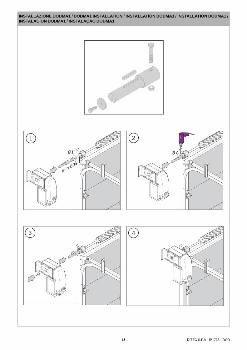
Ø 8
2
3
1
Ø1"
min 60
4
INSTALLAZIONE DODMA1 / DODMA1 INSTALLATION / INSTALLATION DODMA1 / INSTALLATION DODMA1 /INSTALACIÓN DODMA1 / INSTALAÇÃO DODMA1.

16DITEC S.P.A - IP1733 - DOD
Tipologia di installazioneDOD12-14-15 Installato mediante collegamento a catena
Type of installationDOD12-14-15 chain link-up installation
Type d’installationDOD12-14-15 Installé au moyen d’une liaison à chaîne
InstallationsbeispielDOD12-14-15 Installation mit Kettenübersetzung
Tipo de instalaciónDOD12-14-15 Instalado mediante conexión de cadena
Tipo de instalaçãoDOD12-14-15 Instalado mediante ligação na corrente
I
GB
F
D
E
P
VIA M
ONS. BANFI,3
21042 CARONNO P.LLA (V
A)
ITALY
TEL.02/963911 FAX.02/9650314DIT
EC S
.p.A
.
DOOR TYPE
YEAR OF M
ANUFACTURE
VOLTAGE SUPPLY
SERIAL NUMBER
Made in
Italy
00000
00000000000
0000
000V
3x1.
5 m
m² (
DO
D12
-14)
LOGICA21FLOGICTFE1F
4x1.
5 m
m² (
DO
D15
)
3x0.5 mm² (limitswitch)Unlockdevice
4x1.5 mm² (motor)
DOD12-14-15
DODT
DODC30-39-45
CAT1+CATG
MIN
=2,5
m

17 DITEC S.P.A - IP1733 - DOD
DODT
Fig. 4
4. Assemblaggio motore a catenaAssemblare al motore DOD12-14-15 le staffe di fissaggio a muro ela staffa rinvio sblocco, inserire il perno con il pignone (DODT) nel-la posizione richiesta per la trazione (in uno dei due lati del moto-re), come indicato in figura.
4. Motor-chain link-upFasten the wall and release idle brackets to the DOD12-14-15 motorand then fit on the pinion pin (DODT) in the traction position (i.e. oneither one of the two sides of the motor) as shown in the figure.
4. Assemblage du moteur à la chaîneAssembler au moteur DOD12-14-15 les pattes de fixation muraleet la patte du renvoi du dispositif de déverrouillage, insérer l’axeavec le pignon (DODT) dans la position requise pour la traction (surl’un des deux côtés du moteur), comme l’indique la figure.
4. Montage des Motors an die KetteWandbefestigungsbügel und Bügel für denEntriegelungsumlenkblock am Motor DOD12-14-15 befestigen, Stiftmit Ritzel (DODT) in der gewünschten Position für den Antriebeinsetzen (auf einer der beiden Motorseiten), wie in der Abbildungangegeben.
4. Ensamblado del motor a la cadenaEnsamblar al motor DOD12-14-15 las patas de fijación mural y lapata de reenvío del dispositivo de desbloqueo, insertar el pernocon el piñón (DODT) en la posición requerida para la tracción (enuno de los dos lados del motor), como se indica en la figura.
4. Montagem do motor na correnteMontar ao motor DOD12-14-15 os estribos de fixação na parede eo estribo de reenvio do desbloqueio, introduzir o pino com o pinhão(DODT) na posição pedida para a tracção (num dos dois lados domotor), como indicado na figura.
I
GB
F
D
E
P
18DITEC S.P.A - IP1733 - DOD
1
6.35 (1/4")6.35 (1/4")
9.5(3/8")
2 33
4
5
Fig. 5.1
Fig. 5.2
Fig. 5.3
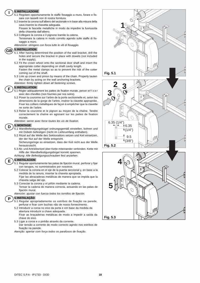
5. INSTALLAZIONE5.1 Regolare opportunamente le staffe fissaggio a muro, forare e fis-
sare con tasselli non di nostra fornitura.5.2 Inserire la corona sull’albero del sezionale e in base alla misura della
cava inserire la chiavetta adeguata.Fissare le fascette metalliche in modo da impedire la fuoriuscitadella chiavetta dall’albero.
5.3 Collegare la corona e il pignone tramite la catena.Tensionare la catena in modo corretto agendo sulle staffe di fis-saggio a muro.
Attenzione: stringere con forza tutte le viti di fissaggio.5. INSTALLATION5.1 After having determined the position of the wall bracket, drill the
holes and secure the bracket in place with dowels (not includedin the supply).
5.2 Fit the crown wheel onto the sectional door shaft and insert theappropriate cotter depending on shaft cavity length.Fasten the metal clamps so as to prevent the risk of the cottercoming out of the shaft.
5.3 Link up crown and pinion by means of the chain. Properly tautenthe chain by acting on the wall anchoring brackets.
Attention: firmly tighten down all fastening screws.5. INSTALLATION5.1 Régler adéquatement les pattes de fixation murale, percer et f i x e r
avec des chevilles (non fournies par nos soins).5.2 Poser la couronne sur l’arbre de la porte sectionnelle et, selon les
dimensions de la gorge de l’arbre, insérer la clavette appropriée.Fixer les colliers métalliques de façon à empêcher que la clavettene sorte de l’arbre.
5.3 Relier la couronne et le pignon au moyen de la chaîne. Tendrecorrectement la chaîne en agissant sur les pattes de fixationmurale.
Attention: serrer avec force toutes les vis de fixation.5. MONTAGE5.1 Wandbefestigungsbügel ordnungsgemäß einstellen, bohren und
mit Dübeln befestigen (nicht im Lieferumfang enthalten).5.2 Ritzel auf die Welle des Sektionaltors setzen und Keil einsetzen,
der der Nut auf der Welle entspricht.Sicherungsringe so einsetzen, dass der Keil nicht aus der Welleherausrutscht.
5.3 Ab- und Antriebsritzel über Kette miteinander verbinden. Kette mitHilfe der Wandbefestigungsbügel korrekt spannen.
Achtung: Alle Befestigungsschrauben fest anziehen.5. INSTALACION5.1 Regular oportunamente las patas de fijación mural, perforar y fijar
con tarugos, no suministrados por nosotros.5.2 Colocar la corona en el eje de la puerta seccional y, en base a la
medida de la ranura, insertar la chaveta apropiada.Fijar las abrazaderas metálicas de manera que se impida que lachaveta salga del eje.
5.3 Conectar la corona y el piñón mediante la cadena.Tensar la cadena de manera correcta, actuando en las patas defijación mural.
Atención: ajustar con fuerza todos los tornillos de fijación.5. INSTALAÇÃO5.1 Regular apropriadamente os estribos de fixação na parede,
perfurar e fixar com buchas não de nosso fornecimento.5.2 Introduzir a coroa no eixo da porta e em base da medida da
abertura introduzir a chave adequada.Fixar as braçadeiras metálicas de modo a impedir a saída dachave do eixo.
5.3 Ligar a coroa e o pinhão através da corrente.Dar tensão a corrente de modo correcto agindo nos estribos defixação na parede.
Atenção: apertar com força todos os parafusos de fixação.
I
GB
F
D
E
P

19 DITEC S.P.A - IP1733 - DOD
VIA MONS. B
ANFI,3
21042 CARONNO P.LLA (VA)
ITALY
TEL.02/963911 FAX.02/9650314DIT
EC S
.p.A
.
DOOR TYPE
YEAR OF MANUFACTURE
VOLTAGE SUPPLY
SERIAL NUMBER
Made in Ita
ly
00000
00000000000
0000
000V
VIA MONS. B
ANFI,3
21042 CARONNO P.LLA (VA)
ITALY
TEL.02/963911 FAX.02/9650314DIT
EC S
.p.A
.
DOOR TYPE
YEAR OF MANUFACTURE
VOLTAGE SUPPLY
SERIAL NUMBER
Made in Ita
ly
00000
00000000000
0000
000V
Unl
ock
INSTALLAZIONE SBLOCCO (SOLO PER DOD12 - 14 - 15) / INSTALLATION RELEASE (ONLY FOR DOD12 - 14- 15) / INSTALLATION JE DÉBLOQUE (SOULEMENT POUR DOD12 - 14 - 15) / INSTALLATION ENTREGIELUNG(NUR FÜR DOD12 - 14 - 15) / INSTALACIÓN DESBLOQUEO (SÓLO POR DOD12 - 14 - 15) / INSTALAÇÃO DODESBLOQUEIO (SOMENTE PARA O DOD12 - 14 - 15).
Fig. 6
Hold tounlock
VIA M
ONS. BANFI,3
21042 CARONNO P.LLA (V
A)
ITALY
TEL.02/963911 FAX.02/9650314DIT
EC S
.p.A
.
DOOR TYPE
YEAR OF M
ANUFACTURE
VOLTAGE SUPPLY
SERIAL NUMBER
Made in
Italy
00000
00000000000
0000
000Vopen
MIN
=2,5
m

20DITEC S.P.A - IP1733 - DOD
7. COLLEGAMENTI ELETTRICI DOD12-14-15Collegare i fili motore ai rispettivi morsetti del quadro elettronico.Attenzione: collegare il cavo di terra del motore alla terra dell’alimen-tazione.Collegare i fili dei finecorsa ai rispettivi morsetti del quadro elettroni-co.Solo DOD 12-14: selezionare il DIP2=OFF del quadro elettronico E1F.
7. DOD12-14-15 WIRINGWire up the motor to the appropriate electric board terminals.Attention: make sure to connect the motor earth to the power earth.Wire up the limit switches to the appropriate electric board terminals.Only DOD 12-14: set DIP2=OFF on E1F control panel.
7. CONNEXIONS ELECTRIQUES DOD12-14-15Relier les fils moteur aux bornes correspondantes dans l’armoireélectrique.Attention: relier le câble de terre du moteur à la terre de l’alimentation.Relier les fils de fins de course aux bornes correspondantes dansl’armoire électrique.Seulement DOD 12-14: sélectionner le commutateur DIP2=OFF del’armoire électrique E1F.
7. ELEKTRISCHE ANSCHLÜSSE DOD12-14-15Motorkabel an die entsprechenden Klemmen der Steuerunganschließen.Achtung: Erdungskabel des Motors an Erdung der Stromversorgunganschließen.Kabel des Endschalter an die entsprechenden Klemmen der Steuerunganschließen.Nur DOD 12-14: den Schalter DIP2 auf der Steuerung E1F in StellungOFF bringen.
7. CONEXIONES ELECTRICAS DOD12-14 230 V~Conectar los hilos del motor a los bornes respectivos del tableroeléctrico.Atención: conectar el cable de tierra del motor a la tierra de laalimentación.Conectar los hilos de los finales de carrera a los respectivos bornesdel tablero.Sólo DOD 12-14: seleccionar el conmutador DIP2=OFF del tableroeléctricoE1F.
7. LIGAÇÕES ELÉCTRICAS DOD12-14 230 V~Ligar os fios do motor aos respectivos bornes do tábua elétrica.Atenção: ligar o cabo de terra do motor à terra da alimentação.Ligar os fios dos fins de curso aos respectivos bornes do tábua elétrica.Somente DOD 12-14: seleccionar o DIP2=OFF do tábua elétrica E1F.
W VU 01112
V
W
U
0
STOP
11
12A
C
Varistor460 V
M3~
FRENOBRAKE
Finecorsa apreOpening limit switch
Finecorsa chiudeClosing limit switch
Motor cable4x1.5 mm²
Limit switch cable3x0.5 mm²
140˚
B Contatto supplementareAdditional switch
Fig. 8
W VU 01112
V
W
U
0
STOP
11
12A
C
com* M
1~
-~
~+
FRENOBRAKE
Finecorsa apreOpening limit switch
Contatto supplementareAdditional switch
Finecorsa chiudeClosing limit switch
B
Motor cable4x1.5 mm²
Limit switch cable3x0.5 mm²
Fig. 7* Dod 12 Capacitor = 25 µFDod 14 Capacitor = 22 µF
Dod 12-14
Dod 15
I
GB
F
D
E
P
DITEC S.p.A.Via Mons. Banfi, 3 - 21042 Caronno Pertusella (VA) - ITALYTel. +39 02 963911 - Fax +39 02 9650314 www.ditec.it - [email protected]
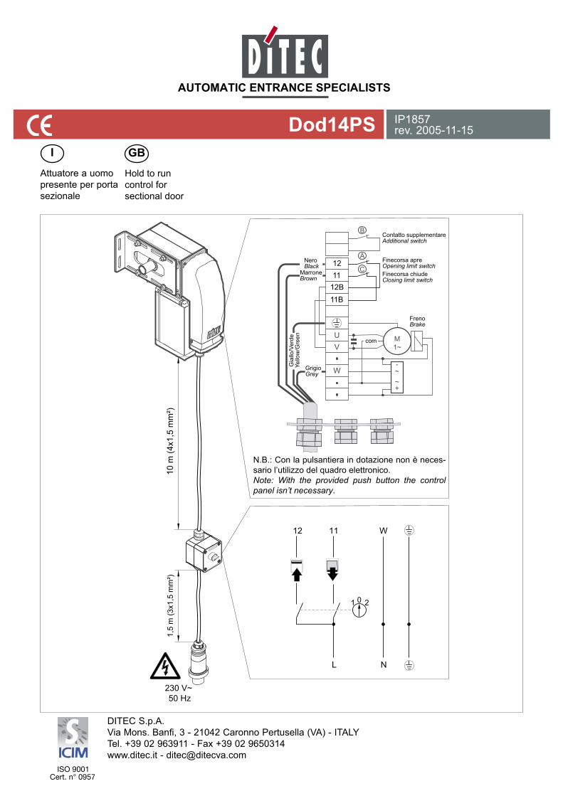
Dod14PS IP1857rev. 2005-11-15
Attuatore a uomo presente per porta sezionale
I GB
Hold to run control for sectional door
V
W
U
A
C
M1~
-~~+
B
01
12 11
L N
W
2
10 m
(4x1
,5 m
m²)
1,5
m (3
x1,5
mm
²)
230 V~ 50 Hz
Finecorsa apreOpening limit switch
Contatto supplementareAdditional switch
NeroBlack
MarroneBrown
GrigioGrey
FrenoBrake
com
Gia
llo/V
erde
Yello
w/G
reen
Finecorsa chiudeClosing limit switch
1211
12B11B
N.B.: Con la pulsantiera in dotazione non è neces-sario l’utilizzo del quadro elettronico.Note: With the provided push button the control panel isn’t necessary.
21 DITEC S.P.A - IP1733 - DOD
B
B
Fig. 9
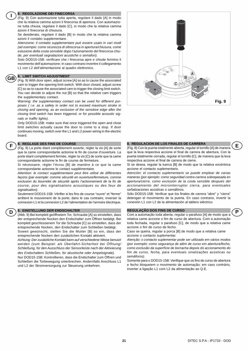
8. REGOLAZIONE DEI FINECORSA(Fig. 9) Con automazione tutta aperta, regolare il dado [A] in modoche la relativa camma azioni il finecorsa di apertura. Con automazio-ne tutta chiusa, regolare il dado [C], in modo che la relativa cammaazioni il finecorsa di chiusura.Se desiderato, regolare il dado [B] in modo che la relativa cammaazioni il contatto supplementare.Attenzione: il contatto supplementare può essere usato in vari modi(ad esempio: come sicurezza di oltrecorsa in apertura/chiusura, comeeslusione della costa sensibile dopo l’azionamento del finecorsa chiu-de, per eventuali segnalazioni acustiche o semafori).Solo DOD15-15B: verificare che i finecorsa apre e chiude fermino ilmovimento dell’automazione; in caso contrario invertire il collegamentoL1 con L2 dell’alimentazione al quadro elettronico.
8. LIMIT SWITCH ADJUSTMENT(Fig. 9) With door open, adjust screw [A] so as to cause the associatedcam to trigger the opening limit switch. With door closed, adjust screw[C] so as to cause the associated cam to trigger the closing limit switch.You can decide to adjust the nut [B] so that the relative cam triggersthe supplementary contact.Warning: the supplementary contact can be used for different pur-poses ( i.e. as a safety in order not to exceed maximum stroke inclosing and opening, as an exclusion of the sensitive edge after theclosing limit switch has been triggered, or for possible acoustic sig-nals or traffic lights).Only DOD15-15B: make sure that once triggered the open and closelimit switches actually cause the door to come to a stop. If doorcontinues moving, switch over the L1 and L2 power wiring in the electricboard.
8. REGLAGE DES FINS DE COURSE(Fig. 9) La porte étant complètement ouverte, régler la vis [A] de sorteque la came correspondante actionne le fin de course d’ouverture. Laporte étant complètement fermée, régler la vis [C] de sorte que la camecorrespondante actionne le fin de course de fermeture.Si nécessaire, régler l’écrou [B] de manière à ce que la camecorrespondante actionne le contact supplémentaire.Attention: le contact supplémentaire peut être utilisé de différentesfaçons (par exemple: comme sécurité en ouverture/fermeture, commeexclusion du bourrelet de sécurité après l’actionnement de la fin decourse, pour des signalisations acoustiques ou des feux designalisation).Seulement DOD15-15B: Vérifier si les fins de course “ouvre” et “ferme”arrêtent le mouvement de la porte; dans le cas contraire, inverser laconnexion L1 et la connexion L2 de l’alimentation de l’armoire électrique.
8. EINSTELLUNG DER ENDSCHALTER(Abb. 9) Bei komplett geöffnetem Tor, Schraube [A] so einstellen, dassder entsprechende Nocken den Endschalter zum Öffnen betätigt. Beikomplett geschlossenem Tor die Schraube [C] so einstellen, dass derentsprechende Nocken, den Endschalter zum Schließen betätigt.Soweit gewünscht, stellen Sie die Mutter [B] so ein, dass derentsprechende Nocken den zusätzlichen Kontakt aktiviert.Achtung: Der zusätzliche Kontakt kann auf verschiedene Weise benutztwerden (zum Beispiel: als Überfahrt-Sicherheit bei Öffnung/Schließung, für den Ausschluss der Sensorleiste nach der Aktivierungdes Endschalters Schließen, für akustische oder Ampelsignale).Nur DOD15-15B: Kontrollieren, dass die Endschalter zum Öffnen undSchließen die Torbewegung unterbrechen. Andernfalls Anschluss L1und L2 der Stromversorgung zur Steuerung umkehren.
I
8. REGULACION DE LOS FINALES DE CARRERA(Fig. 8) Con la puerta totalmente abierta, regular el tornillo [A] de maneraque la leva respectiva accione el final de carrera de abertura. Con lapuerta totalmente cerrada, regular el tornillo [C], de manera que la levarespectiva accione el final de carrera de cierre.Si se desea, regular la tuerca [B] de modo que la relativa excéntricaaccione el contacto suplementario.Atención: el contacto suplementario se puede emplear de variasmaneras (por ejemplo: como seguridad contra carrera sobrepasada enapertura/cierre, como exclusión de la costa sensible después delaccionamiento del microinterruptor cierra, para eventualesseñalizaciones acústicas o semáforos.Sólo DOD15-15B: Verificar que los finales de carrera “abre” y “cierra”detengan el movimiento de la puerta. En caso contrario, invertir laconexión L1 con L2 de la alimentación al tablero eléctrico.
REGULAÇÃO DOS FINS DE CURSOCom a automação toda aberta, regular o parafuso [A] de modo que arelativa came accione o fim de curso de abertura. Com a automaçãotoda fechada, regular o parafuso [C], de modo que a relativa cameaccione o fim de curso de fecho.Caso se queira, regular a porca [B] de modo que a relativa cameaccione o contacto suplementar.Atenção: o contacto suplementar pode ser utilizado em vários modos(por exemplo: como segurança de além de curso em abertura/fecho,como exclusão da superfície de borracha depois do accionamento dofim de curso, fecha, para eventuais sinalizações acústicas ousemáforos).Somente para o DOD15-15B: Verifique que os fins de curso de aberturae fecho bloqueiem o movimento de automação; em caso contrário,inverter a ligação L1 com L2 da alimentação ao Q.E.
GB
F
D
E
P
22DITEC S.P.A - IP1733 - DOD
3x1.5 mm² (DOD12-14)
E1FLOGICTF
4x1.5 mm² (DOD15)
3x0.5 mm² (limitswitch)
Unlockdevice
4x1.5 mm² (motor)
DOD12-14-15DODT
DODRIN1
Tipologia di installazioneDOD12-14-15 Installato su portone scorrevole
Type of installationDOD12-14-15 Installed on sliding door
Type d’installationDOD12-14-15 Installé sur porte coulissante
InstallationsbeispielDOD12-14-15 Installiert an Schiebetor
Tipo de instalaciónDOD12-14-15 Establecido sobre portón corredizo
Tipo de instalaçãoDOD12-14-15 Instalado no portão de correr
TipoType
DOD15
DOD12
PignonePinion
CoronaCrown
Rapporto diriduzione
Reductionratio
1:1
1:1
CoppiaTorque
Nm
65
45
Velocità dirotazione
Rotating speedRPM
32
32DODT(Z24)
DODT(Z24)
DODRIN1(Z24)
DODRIN1(Z24)
Velocitàdell’automazioneSpeed of the door
m/s
Corsa maxMax door run
m
Forza maxMax force
N
0,16
0,16
8,35
8,35
1300
900
DOD14 1:1 60 22DODT(Z24)
DODRIN1(Z24) 0,11 8,35 1200
I
GB
F
D
E
P

23 DITEC S.P.A - IP1733 - DOD
3x1.5 mm² (DOD12-14)
E1FLOGICTF
4x1.5 mm² (DOD15)
3x0.5 mm² (limitswitch)
Unlockdevice
4x1.5 mm² (motor)
DOD12-14-15DODT
DODRIN1
Tipologia di installazioneDOD12-14-15 Installato su portone a libroN.B.: per un corretto funzionamento il portone deve essere munito di deragliatore e l’attacco dellacatena sull’anta deve essere rotante.
Type of installationDOD12-14-15 Installed on folding doors.Attention: for proper operation the door shall be equipped with a derailment device and the chainfastening bracket on the wing must be rotating.
Type d’installationDOD12-14-15 Installé sur portes pliantesN.B. : pour un bon fonctionnement, la porte doit être munie d’un dérailleur et la fixation de la chaînesur le vantail doit être pivotante.
InstallationsbeispielDOD12-14-15 Installiert an FaltorenN.B.: Für einen einwandfreien Betrieb muss das Tor mit entsprechenden mechanischen Beschlägenausgestattet sein.
Tipo de instalaciónDOD12-14-15 Establecido sobre plegablesN.B.: para un correcto funcionamiento el cierre tiene que estar dotado de un descarrilador y launión de la cadena en la hoja tiene que ser giratoria.
Tipo de instalaçãoDOD12-14-15 Instalado na porta de foleOBS.: para um funcionamento correcto o portão deve ser equipado de um dispositivo para desbloquearo engate da corrente no portão.
TipoType
DOD15
DOD12
PignonePinion
CoronaCrown
Rapporto diriduzione
Reductionratio
1:1
1:1
CoppiaTorque
Nm
65
45
Velocità dirotazione
Rotating speedRPM
32
32DODT(Z24)
DODT(Z24)
DODRIN1(Z24)
DODRIN1(Z24)
Velocitàdell’automazioneSpeed of the door
m/s
Corsa maxMax door run
m
Forza maxMax force
N
0,16
0,16
8,35
8,35
1300
900
DOD14 1:1 60 22DODT(Z24)
DODRIN1(Z24) 0,11 8,35 1200
I
GB
F
D
E
P
24DITEC S.P.A - IP1733 - DOD
3x1.5 mm² (DOD12-14)
E1FLOGICTF
4x1.5 mm² (DOD15)
3x0.5 mm² (limitswitch)
4x1.5 mm² (motor)
DOD12-14-15DODTC1
Unlockdevice
Tipologia di installazioneDOD12-14-15 con DODTC1 Installato su portone scorrevole
Type of installationDOD12-14-15 with DODTC1 Installed on sliding door
Type d’installationDOD12-14-15 avec DODTC1 Installé sur porte coulissante
InstallationsbeispielDOD12-14-15 mit DODTC1 Installiert an Schiebetor
Tipo de instalaciónDOD12-14-15 con DODTC1 Establecido sobre portón corredizo
Tipo de instalaçãoDOD12-14-15 com DODTC1 Instalado no portão de correr
DODTC1
DODT
TipoType
DOD15
DOD12
PignonePinion
CoronaCrown
Rapporto diriduzione
Reductionratio
1:1
1:1
CoppiaTorque
Nm
65
45
Velocità dirotazione
Rotating speedRPM
32
32DODT(Z24)
DODT(Z24)
DODRIN1(Z24)
DODRIN1(Z24)
Velocitàdell’automazioneSpeed of the door
m/s
Corsa maxMax door run
m
Forza maxMax force
N
0,16
0,16
8,35
8,35
1300
900
DOD14 1:1 60 22DODT(Z24)
DODRIN1(Z24) 0,11 8,35 1200
I
GB
F
D
E
P
25 DITEC S.P.A - IP1733 - DOD
11. PIANO DI MANUTENZIONE (ogni 6 mesi)Senza alimentazione 230 V~ oppure 400 V~:- La manutenzione e la lubrificazione di parti meccaniche si devono
eseguire ad automazione abbassata.- Verificare il funzionamento del dispositivo di rottura dei cavi e delle
molle.- Verificare l’usura delle funi di sollevamento.- Verificare il libero scorrimento dei cavi nei tamburi.- Lubrificare periodicamente le cerniere i cuscinetti i perni delle ruote e
le molle di torsione.- Controllare che non ci siano ostacoli che alterino il corretto scorrimento
delle ruote nelle guide.- Controllare la corretta bilanciatura dell’automazione
sezionale.- Verificare che la struttura superiore di scorrimento sia perfettamente
ancorata al solaio soprastante e che quindi non siano presenti difetti,pieghe o cedimenti.
- Controllare che non vi siano viti o bulloni allentati.- Non modificare nessuna parte del sistema di sollevamento e/o
scorrimento.Ridare alimentazione 230 V~ oppure 400 V~:- Controllare il corretto azionamento dei finecorsa.- Controllare il corretto funzionamento di tutte le funzioni di comando e
sicurezza.ATTENZIONE: Per le parti di ricambio fare riferimento al listinoricambi.11. MAINTENANCE PLAN (once every 6 months)Power off completely, whether 230 V~ or 400 V~, before anymaintenance operation.- Lubrication of mechanical parts must be performed with door down.- Make sure that cable and spring breakage device is in perfect working
order.- Check lift-cable wear.- Make sure that the cables run smoothly in the drums.- Periodically grease the hinges, ball-bearings, wheel pins, and torsional
springs.- Check for any obstacles that may hinder the wheels from properly
running in the guides.- To check the correct balancing of the sectional automation.- Make sure that the overhead sliding structure is firmly fastened to the
ceiling and perfectly free from any defects, bending or buckling.- Make sure that there are no loose bolts or screws.- Absolutely avoid making any changes to the hoisting and/or sliding
system.Power back on (230 V~ or 400 V~) and check that:- Limit switches are working properly;- All control and safety functions are in good working order.ATTENTION: For spare parts see the spare parts list.11. PROGRAMME D’ENTRETIEN (tous les 6 mois)Sans alimentation 230 V~ ou 400 V~:- L’entretien et le graissage des pièces mécaniques doivent s’effectuer
quand la porte est abaissée.- Vérifier le fonctionnement du dispositif de rupture des câbles et des
ressorts.- Vérifier l’usure des câbles de levage.- Vérifier si les câbles glissent librement dans les tambours.- Lubrifier périodiquement les charnières, les roulements, les axes
des roues et les ressorts de torsion.- Contrôler qu’il n’y a pas d’obstacles gênant le bon coulissement des
roues sur les rails.- Contrôler le balancement correct de la porte -leur.- Vérifier que la structure supérieure de coulissement est parfaitement
ancrée au plafond et qu’il n’y a donc aucun défaut, pli ou affaissement.- Contrôler qu’il n’y a pas de vis ou de boulons desserrés.- Ne modifier aucune partie du système de levage et/ou de
coulissement.Rebrancher l’alimentation 230 V~ ou 400 V~:- Contrôler le bon déclenchement des fins de course.- Contrôler le bon fonctionnement de toutes les fonctions de commande
et de sécurité.ATTENTION: Pour les pièces de rechange, se reporter au cataloguecorrespondant.
11. WARTUNGSARBEITEN (alle 6 Monate)Ohne Stromversorgung 230 V~ oder 400 V~:- Die Wartung und Schmierung der mechanischen Teile ist bei
geschlossenem Tor durchzuführen.- Funktionsweise der Seil- und Federbruchsicherung überprüfen.- Abnutzung derSeile überprüfen.- Freien Lauf der Seile in den Seiltrommeln überprüfen.- Scharniere, Rollen und Torsionsfedern regelmäßig schmieren.- Überprüfen, dass keine Hindernisse vorhanden sind, die ein korrektes
Gleiten der Rollen in den Führungen berhindern.- Den korrekten Federausgleich des Tores kontrollieren.- Überprüfen, dass die Laufschienen einwandfrei verankert sind und
dass keine Defekte, oder Verformungen vorhanden sind.- Kontrollieren, dass alle Schrauben und Bolzen fest angezogen sind.- Die Teile des Hebe- und/oder Gleitsystems nicht ändern.Strom 230 V~ oder 400 V~ zuführen:- Korrekte Funktionsweise der Endschalter kontrollieren.- Korrekte Funktionsweise aller Steuer- und Sicherheitsfunktionen
überprüfen.ACHTUNG: Für Ersatzteile verweisen wir auf die Ersatzteil-Preisliste.11. PROGRAMA DE MANTENIMIENTO (cada 6 meses)Sin alimentación 230 V~ o bien 400 V~:- El mantenimiento y lubricación de las partes mecánicas se deberán
de llevar a cabo con la puerta bajada.- Verificar el funcionamiento del dispositivo de ruptura de los cables
y de los resortes.- Verificar el desgaste de los cables de elevación.- Verificar si los cables deslizan libremente en los tambores.- Lubricar periódicamente las bisagras, los rodamientos, los pernos
de las ruedas y los resortes de torsión.- Controlar que no existan obstáculos que alteren el correcto
desplazamiento de las ruedas en las guías.- Controlar el correcto balance de la puerta seccional.- Verificar que la estructura superior de desplazamiento se encuentre
perfectamente anclada al piso sobre el que se encuentra y que nohayan defectos, pliegues o aflojamientos.
- Controlar que no existan tornillos o pernos flojos.- No modificar ninguna parte del sistema de elevación y/o
desplazamiento.Volver a dar alimentación de 230 V~ o de 400 V~:- Controlar el correcto accionamiento de los finales de carrera.- Controlar el correcto funcionamiento de todas las funciones de mando
y seguridad.ATENCIÓN: Para las piezas de repuesto, hacer referencia a la listade repuestos.11. PLANO DE MANUTENÇÃO (a cada 6 meses)Sem alimentação 230 V~ ou 400 V~:- A manutenção e a lubrificação de partes mecânicas devem ser
realizadas com a porta abaixada.- Verifique o funcionamento do dispositivo de ruptura dos cabos e
das molas.- Verifique o desgaste das cordas de elevação.- Verifique o deslizamento dos cabos nos tambores.- Lubrifique periodicamente as dobradiças, os rolamentos, os pinos
das rodas e as molas de torção.- Controle que não sejam presentes obstáculos que alterem o correcto
deslizamento das rodas nas guias.- Controle a correcta compensação da porta seccionada.- Verifique que a estrutura superior de deslizamento esteja
perfeitamente ancorada ao soalho e que, portanto não sejampresentes defeitos, dobras ou cedimentos.
- Controle que não sejam presentes parafusos ou porcas comferrugens.
- Não modificar nenhuma parte do sistema de elevação e/oudeslizamento.
Ligar novamente a alimentação de 230 V~ ou 400 V~:- Controle o accionamento correcto dos fins de curso.- Controle o funcionamento correcto de todas as funções de comando
e segurança.ATENÇÃO: Para as partes de reposição fazer referência ao catálogodas peças de reposição.
I
GB
F
D
E
P

RELEASE INSTRUCTIONImportant: The overhead door may not be correctlybalanced. Release operations and manual door move-
ment must be performed with the motor stopped, by trainedpersonnel.In case of malfunction or power failure, press the emergencystop button [1] (COMPLETE STOP), unlock the motor by pullingthe cord or by rotating the DEB04 [2] handle and manually liftthe door [3].If the DodSBV/SBO is used for opening or to close the door toact on the crank (fig. 2).Attention: Dod12B, Dod14B end Dod15B gear motor can bemanually actuated only by means of DodSBV or Dod SBOdevice.
GENERAL SAFETY PRECAUTIONSThe following precautions are an integral and essentialpart of the product and must be supplied to the user.
Read them carefully as they contain important indications forthe safe installation, use and maintenace.These instruction must be kept and forwarded to all possiblefuture user of the system.This product must be used only for that which it has beenexpressely designed.Any other use is to be considered improper and thereforedangerous.The manufacturer cannot be held responsible for possibledamage caused by improper, erroneous or unresonable use.Avoid operating in the proximity of the hinges or movingmechanical parts.Do not enter the field of action of the motorised door or gatewhile in motion.Do not obstruct the motion of the motorised door or gate as thismay cause a situation of danger.Do not lean against or hang on to the barrier when it is moving.Do not allow children to play or stay within the field of action ofthe motorised door or gate.Keep remote control or any other control devices out of thereach of children, in order to avoid possible involuntary activationof the motorised door or gate.In case of breack down or malfunctioning of the product,disconnect from mains, do not attempt to repair or intervenedirectly and contact only qualified personnel.Failure to comply with the above may create a situation ofdanger.All cleaning, maintenance or repair work must be carried out byqualified personnel.In order to guarantee that the system works efficiently andcorrectly it is indispensable to comply with the manufacturer’sindications thus having the periodic maintenance of themotorised door or gate carried out by qualified personnel.In particular regular checks are recommended in order to verifythat the safety devices are operating correctly. All installation,maintenance and repair work must be documented and madeavailable to the user.
OPERATING INSTRUCTION FOR INDUSTRIAL SECTIONAL DOOR AUTOMATIONS
ON
OFF
DITEC S.p.A.Via Mons. Banfi, 321042 Caronno Pertusella (VA) - ITALYTel. +39 02 963911 - Fax +39 02 9650314www.ditec.it - [email protected]
TEA
R O
FF A
ND
DEL
IVER
TO
USE
R
Installer:
1
DEB04 OPTIONAL
VIA MONS. BANFI,3
21042 CARONNO P.LLA (VA)
ITALY
TEL.02/963911 FAX.02/9650314DITEC S
.p.A
.
DOOR TYPE
YEAR OF MANUFACTURE
VOLTAGE SUPPLY
SERIAL NUMBER
Made in Italy
00000
00000000000
0000
000V
3
Fig. 1
VIA M
ONS. BANFI,3
21042 CARONNO P.LLA (V
A)
ITALY
TEL.02/963911 FAX.02/9650314DIT
EC S
.p.A
.
DOOR TYPE
YEAR OF MANUFACTURE
VOLTAGE SUPPLY
SERIAL NUMBER
Made in
Italy
00000
00000000000
0000
000V
Fig. 2
open or close
GB
21
2
DITEC FRANCE PALAISEAU Tel. +33 1 64532860 Fax +33 1 64532861 www.ditec.frDITEC DEUTSCHLAND OBERURSEL Tel. +49 6171914150 Fax +49 61719141555 www.ditec-germany.deDITEC SVIZZERA MENDRISIO Tel. +41 91 6463339 Fax +41 91 6466127 www.ditecswiss.chDITEC AMERICA FT. LAUDERDALE USA Tel. +1 954 9624505 Fax +1 954 9626824 www.ditecamerica.com
DITEC S.p.A.Via Mons. Banfi, 3 - 21042 Caronno Pertusella (VA) - ITALYTel. +39 02 963911 - Fax +39 02 9650314www.ditec.it - [email protected]
Quarto d’Altino (VE) - ITALIA
Caronno Pertusella (VA) - ITALIA Palaiseau - FRANCE
Mendrisio - SWISS
Oberursel - GERMANY
Ft. Lauderdale - USA