![IP surveillance TroubleShooting guide V0.9 2006053 - ACTi surveillance... · This [IP Surveillance Troubleshooting Guide] contains step by step procedure for you to solve a problem.](https://static.fdocuments.us/doc/165x107/5a70e2ff7f8b9a9d538c6426/ip-surveillance-troubleshooting-guide-v09-2006053-actiwww2acticomfilesupportdocdownloadip.jpg)
IP Surveillance TroubleShooting Guide_V0.9
348
IP Survei ll ance Tro ubl eShootin g Gui de V ersion: 0.9 Release: 20060527
Transcript of IP Surveillance TroubleShooting Guide_V0.9

8/21/2019 IP Surveillance TroubleShooting Guide_V0.9
http://slidepdf.com/reader/full/ip-surveillance-troubleshooting-guidev09 1/347
IP SurveillanceTroubleShooting Guide
Version: 0.9
Release: 20060527

8/21/2019 IP Surveillance TroubleShooting Guide_V0.9
http://slidepdf.com/reader/full/ip-surveillance-troubleshooting-guidev09 2/347

8/21/2019 IP Surveillance TroubleShooting Guide_V0.9
http://slidepdf.com/reader/full/ip-surveillance-troubleshooting-guidev09 3/347
1
Chapter. 1. Introduction ACTi provides you a series of guides for your project from proposal stage to
maintenance stage. They work as below
[IP surveillance Proposal Guide]: Making proposal to your customer [IP Surveillance Deployment Guide]: Fulfill your project from proposal
to practical to your customer.
[Tech Support and Troubleshooting Guide]: Find the root cause of
your problem and solve it.
This [IP Surveillance Troubleshooting Guide] contains step by step
procedure for you to solve a problem. First, we divide the troubleshooting by
solutions into “IP surveillance solution” and “Hybrid IP surveillance solution”.
We start from “Define your problem type” to know what kind of problem it
is and define the problem type. Then we follow the problem type and refer to
the chapters after to know the possible cause of this type of problem. After
that, we can follow the introduction to clarify what is the actual cause of the
problem this time and how to solve it.
We will not include everything in this guide. Please refer to1. [IP Surveillance Proposal Guide] for how make a proposal to your
customer.2. [IP Surveillance Deployment Guide] for how to fulfill your project from
proposal to practical to your customer.
Stage1.
Know your problem Type
Stage2.
Find out the possible cause
Stage3.
Find the real cause and find
respective solution
8/21/2019 IP Surveillance TroubleShooting Guide_V0.9
http://slidepdf.com/reader/full/ip-surveillance-troubleshooting-guidev09 4/347
2
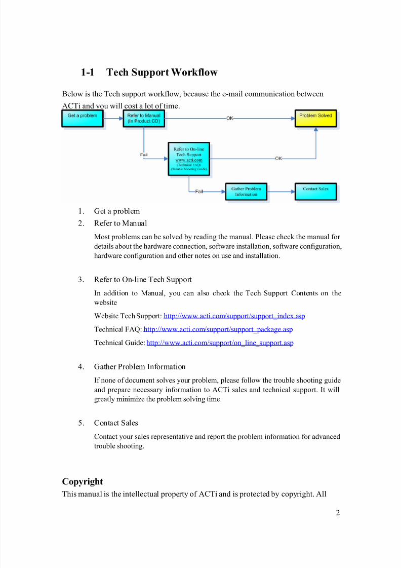
1-1 Tech Support Workflow
Below is the Tech support workflow, because the e-mail communication between
ACTi and you will cost a lot of time.
1. Get a problem
2. Refer to Manual
Most problems can be solved by reading the manual. Please check the manual for
details about the hardware connection, software installation, software configuration,
hardware configuration and other notes on use and installation.
3. Refer to On-line Tech Support
In addition to Manual, you can also check the Tech Support Contents on the
website
Website Tech Support: http://www.acti.com/support/support_index.asp
Technical FAQ: http://www.acti.com/support/support_package.asp
Technical Guide: http://www.acti.com/support/on_line_support.asp
4. Gather Problem Information
If none of document solves your problem, please follow the trouble shooting guide
and prepare necessary information to ACTi sales and technical support. It will
greatly minimize the problem solving time.
5. Contact Sales
Contact your sales representative and report the problem information for advanced
trouble shooting.
Copyright
This manual is the intellectual property of ACTi and is protected by copyright. All
8/21/2019 IP Surveillance TroubleShooting Guide_V0.9
http://slidepdf.com/reader/full/ip-surveillance-troubleshooting-guidev09 5/347
3
Rights are reserved. No part of this document maybe reproduced or transmitted for
any
purpose by any means including electronic or mechanical without the official written
permission from ACTi.
Trademarks
All names used in this manual for hardware and software are probably registered
trademarks of respective companies.
Liability
Every care has been taken during writing this manual. Please inform your local office
if you find any inaccuracies or omissions. We cannot be held responsible for any
typographical or technical errors and reserve the right to make changes to the product
and manuals without prior notice.

8/21/2019 IP Surveillance TroubleShooting Guide_V0.9
http://slidepdf.com/reader/full/ip-surveillance-troubleshooting-guidev09 6/347
4
Table of Contents
CHAPTER. 1. INTRODUCTION .....................................................................................................1
1-1 TECH SUPPORT WORK FLOW ..................................................................................................2
CHAPTER. 2. IP SURVEILLANCE SOLUTION TROUBLE SHOOTING SECTION ERROR!
BOOKMARK NOT DEFINED.
CHAPTER. 3. FIND YOUR PROBLEM TYPE ............. ERROR! BOOKMARK NOT DEFINED.
3-1 PROBLEM T YPE TABLE................................................... ERROR ! BOOKMARK NOT DEFINED.
CHAPTER. 4. LOGIN PROBLEM........................... ................................ ......................................14
4-1 FIND OUT THE POSSIBLE CAUSE ............................................................................................144-2 LOGIN PROBLEM TYPE 1......................................................................................................16
4-3 LOGIN PROBLEM TYPE 2......................................................................................................18
4-4 LOGIN PROBLEM TYPE 3......................................................................................................2 7
CHAPTER. 5. MONITOR PROBLEM ......................................................................... .................31
5-1 FIND OUT THE POSSIBLE CAUSE ............................................................................................31
5-2 MONITOR PROBLEM T YPE 1.................................................................................................33
5-3 MONITOR PROBLEM T YPE 2.................................................................................................38
5-4 MONITOR PROBLEM T YPE 3.................................................................................................41
5-5 MONITOR PROBLEM T YPE 4.................................................................................................46
5-6 MONITOR PROBLEM T YPE 5.................................................................................................50
5-7 MONITOR PROBLEM T YPE 6.................................................................................................5 0
CHAPTER. 6. PTZ PROBLEM ......................................................................................................57
6-1 FIND OUT THE POSSIBLE CAUSE ............................................................................................57
6-2 PTZ PROBLEM TYPE 1..........................................................................................................59
6-3 PTZ PROBLEM TYPE 2..........................................................................................................64
6-4 PTZ PROBLEM TYPE 3..........................................................................................................77
6-5 PTZ PROBLEM TYPE 4..........................................................................................................81
6-6 PTZ PROBLEM TYPE 5..........................................................................................................9 1
CHAPTER. 7. VIDEO QUALITY PROBLEM......................................... ...................................105
7-1 FIND OUT THE POSSIBLE CAUSE ..........................................................................................105
7-2 VIDEO QUALITY PROBLEM TYPE 1.....................................................................................107
7-3 VIDEO QUALITY PROBLEM TYPE 2.....................................................................................114
7-4 VIDEO QUALITY PROBLEM TYPE 3.....................................................................................11 9

8/21/2019 IP Surveillance TroubleShooting Guide_V0.9
http://slidepdf.com/reader/full/ip-surveillance-troubleshooting-guidev09 7/347
5
7-5 VIDEO QUALITY PROBLEM TYPE 4.....................................................................................124
7-6 VIDEO QUALITY PROBLEM TYPE 5.....................................................................................127
7-7 VIDEO QUALITY PROBLEM TYPE 6.....................................................................................130
7-8 VIDEO QUALITY PROBLEM TYPE 7.....................................................................................130
7-9 VIDEO QUALITY PROBLEM TYPE 8.....................................................................................137
7-10 VIDEO QUALITY PROBLEM TYPE 9.....................................................................................140
7-11 VIDEO QUALITY PROBLEM TYPE 10...................................................................................145
7-12 VIDEO QUALITY PROBLEM TYPE 11...................................................................................14 8
CHAPTER. 8. LATENCY PROBLEM................................ ......................................................... 150
8-1 FIND OUT THE POSSIBLE CAUSE ..........................................................................................150
8-2 LATENCY PROBLEM TYPE 1................................................................................................151
8-3 LATENCY PROBLEM TYPE 2................................................................................................15 6
CHAPTER. 9. VIDEO JITTER PROBLEM.......................... ...................................................... 159
9-1 FIND OUT THE POSSIBLE CAUSE ..........................................................................................159
9-2 VIDEO JITTER PROBLEM TYPE 1 .........................................................................................160
9-3 VIDEO JITTER PROBLEM TYPE 2 .........................................................................................163
CHAPTER. 10. DIO EVENT PROBLEM .......................................................................... ............167
10-1 FIND OUT THE POSSIBLE CAUSE ..........................................................................................167
10-2 DIO PROBLEM TYPE 1........................................................................................................171
10-3 DIO PROBLEM TYPE 2........................................................................................................174
10-4 DIO PROBLEM TYPE 3........................................................................................................177
10-5 DIO PROBLEM TYPE 4........................................................................................................179
10-6 DIO PROBLEM TYPE 5........................................................................................................182
10-7 DIO PROBLEM TYPE 6........................................................................................................185
10-8 DIO PROBLEM TYPE 7........................................................................................................187
10-9 DIO PROBLEM TYPE 8........................................................................................................190
10-10 DIOPROBLEM TYPE 9........................................................................................................196
10-11 DIOPROBLEM TYPE 10......................................................................................................202
10-12 DIOPROBLEM TYPE 11......................................................................................................208
10-13 DIOPROBLEM TYPE 12......................................................................................................211
10-14 DIOPROBLEM TYPE 13......................................................................................................217
10-15 DIOPROBLEM TYPE 14......................................................................................................223
10-16 DIOPROBLEM TYPE 15......................................................................................................226
10-17 DIOPROBLEM TYPE 16......................................................................................................23 1
CHAPTER. 11. MD EVENT PROBLEM................................ ....................................................... 234

8/21/2019 IP Surveillance TroubleShooting Guide_V0.9
http://slidepdf.com/reader/full/ip-surveillance-troubleshooting-guidev09 8/347
6
11-1 FIND OUT THE POSSIBLE CAUSE ..........................................................................................234
11-2 MD PROBLEM TYPE 1........................................................................................................239
11-3 MD PROBLEM TYPE 2........................................................................................................242
11-4 MD PROBLEM TYPE 3........................................................................................................245
11-5 MD PROBLEM TYPE 4........................................................................................................245
11-6 MD PROBLEM TYPE 5........................................................................................................250
11-7 MD PROBLEM TYPE 6........................................................................................................253
11-8 MD PROBLEM TYPE 7........................................................................................................256
11-9 MD PROBLEM TYPE 8........................................................................................................256
11-10 MD PROBLEM TYPE 9........................................................................................................262
11-11 MD PROBLEM TYPE 10......................................................................................................273
11-12 MD PROBLEM TYPE 11......................................................................................................276
11-13 MD PROBLEM TYPE 12......................................................................................................276
11-14 MD PROBLEM TYPE 13......................................................................................................282
11-15 MD PROBLEM TYPE 14......................................................................................................291
11-16 MD PROBLEM TYPE 15......................................................................................................297
11-17 MD PROBLEM TYPE 16......................................................................................................300
11-18 MD PROBLEM TYPE 17......................................................................................................301
11-19 MD PROBLEM TYPE 18......................................................................................................302
11-20 MD PROBLEM TYPE 19......................................................................................................303
11-21 MD PROBLEM TYPE 20......................................................................................................30 4
CHAPTER. 12. RECORD & PLAYBACK PROBLEM ...............................................................307
12-1 FIND OUT THE POSSIBLE CAUSE ..........................................................................................307
12-2 R ECORD & PLAYBACK PROBLEM TYPE 1...........................................................................309
12-3 R ECORD & PLAYBACK PROBLEM TYPE 2...........................................................................309
12-4 R ECORD & PLAYBACK PROBLEM TYPE 3...........................................................................314
12-5 R ECORD & PLAYBACK PROBLEM TYPE 4...........................................................................315
12-6 R ECORD & PLAYBACK PROBLEM TYPE 5...........................................................................319
12-7 R ECORD & PLAYBACK PROBLEM TYPE 6...........................................................................321
12-8 R ECORD & PLAYBACK PROBLEM TYPE 7...........................................................................323
12-9 R ECORD & PLAYBACK PROBLEM TYPE 8...........................................................................324
12-10 R ECORD & PLAYBACK PROBLEM TYPE 9...........................................................................326
12-11 R ECORD & PLAYBACK PROBLEM TYPE 10.........................................................................329
12-12 R ECORD & PLAYBACK PROBLEM TYPE 11.........................................................................331
12-13 R ECORD & PLAYBACK PROBLEM TYPE 12.........................................................................333
12-14 R ECORD & PLAYBACK PROBLEM TYPE 13.........................................................................336
12-15 R ECORD & PLAYBACK PROBLEM TYPE 14.........................................................................338

8/21/2019 IP Surveillance TroubleShooting Guide_V0.9
http://slidepdf.com/reader/full/ip-surveillance-troubleshooting-guidev09 9/347
7
12-16 R ECORD & PLAYBACK PROBLEM TYPE 15.........................................................................340
12-17 R ECORD & PLAYBACK PROBLEM TYPE 16.........................................................................341

8/21/2019 IP Surveillance TroubleShooting Guide_V0.9
http://slidepdf.com/reader/full/ip-surveillance-troubleshooting-guidev09 10/347
8
Chapter. 2. Find your solution typeWe divided the IP surveillance Troubleshooting guide into two sections by
solution.
a. IP Surveillance solution Troubleshooting b. Hybrid IP surveillance solution Troubleshooting
Each section covers the troubleshooting material for different IP surveillance
solutions. Please refer to the description below to find your find the solution type
and go to respective sections for more details.
2-1-1 IP Surveillance solution
In Pure IP solution, everything is transmitted and stored digitally. The
images are transmitted via Ethernet Network instead of the coaxial cable.
The images are stored into a hard drive instead of cassettes.
Please refer to In Pure IP solution, everything is transmitted and stored
digitally. The images are transmitted via Ethernet Network instead of the
coaxial cable. The images are stored into a hard drive instead of cassettes.
Network
Management
Storage
maging
Monitor
Management
8/21/2019 IP Surveillance TroubleShooting Guide_V0.9
http://slidepdf.com/reader/full/ip-surveillance-troubleshooting-guidev09 11/347
9
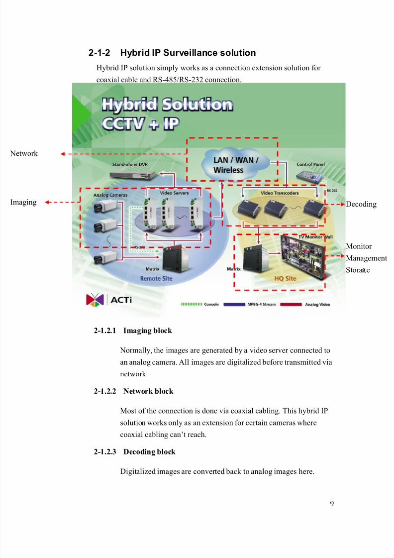
2-1-2 Hybrid IP Surveillance solution
Hybrid IP solution simply works as a connection extension solution for
coaxial cable and RS-485/RS-232 connection.
2-1.2.1 Imaging block
Normally, the images are generated by a video server connected to
an analog camera. All images are digitalized before transmitted via
network.
2-1.2.2 Network block
Most of the connection is done via coaxial cabling. This hybrid IP
solution works only as an extension for certain cameras where
coaxial cabling can’t reach.
2-1.2.3 Decoding block
Digitalized images are converted back to analog images here.
maging
Network
Monitor
Management
Stora e
Decoding

8/21/2019 IP Surveillance TroubleShooting Guide_V0.9
http://slidepdf.com/reader/full/ip-surveillance-troubleshooting-guidev09 12/347
10
2-1.2.4 Monitor/Management block
All the monitor, management and storage are done via
conventional DVR, VCRs and Matrix.

8/21/2019 IP Surveillance TroubleShooting Guide_V0.9
http://slidepdf.com/reader/full/ip-surveillance-troubleshooting-guidev09 13/347
11
Chapter. 3. IP Surveillance solutiontroubleshooting section
This section includes chapters from 3 to 13. It includes step by step procedure for
you to know your problem kind, define your problem type, find possible causes,how to clarify each possible cause and how to solve the problem.
3-1 IP Surveillance Solution building blocks
3-1.1.1 Imaging block
The images are generated by IP camera or a video server connected
to an analog camera. All images are digitalized before transmitted
via network.
3-1.1.2 Network block
All the data is transmitted via Ethernet Network. There’s no
Network
Management
Storage
maging
Monitor
Management

8/21/2019 IP Surveillance TroubleShooting Guide_V0.9
http://slidepdf.com/reader/full/ip-surveillance-troubleshooting-guidev09 14/347
12
coaxial cabling to transmit the video clip. The network could be a
LAN (Local Area Network) or a WAN (Wide Area Network)
including Internet.
3-1.1.3 Monitor block
Live images and recorded files are played onto PC monitor instead
of Analog TV.
3-1.1.4 Monitor block
All the images, events are recorded into a PC with network
connectivity to this network. The images stored can be playback
and searched in the future.
.
8/21/2019 IP Surveillance TroubleShooting Guide_V0.9
http://slidepdf.com/reader/full/ip-surveillance-troubleshooting-guidev09 15/347
13
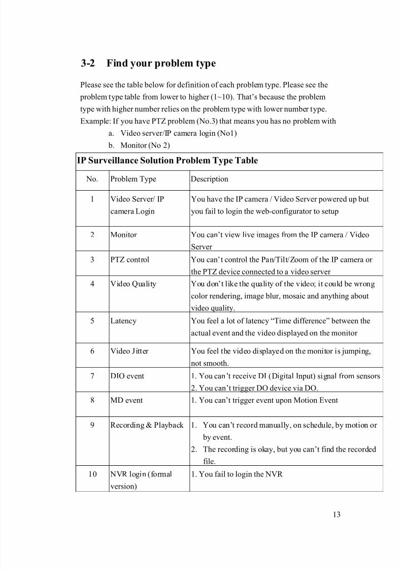
3-2 Find your problem type
Please see the table below for definition of each problem type. Please see the
problem type table from lower to higher (1~10). That’s because the problemtype with higher number relies on the problem type with lower number type.
Example: If you have PTZ problem (No.3) that means you has no problem with
a. Video server/IP camera login (No1)
b. Monitor (No 2)
IP Surveillance Solution Problem Type Table
No. Problem Type Description
1 Video Server/ IPcamera Login
You have the IP camera / Video Server powered up butyou fail to login the web-configurator to setup
2 Monitor You can’t view live images from the IP camera / Video
Server
3 PTZ control You can’t control the Pan/Tilt/Zoom of the IP camera or
the PTZ device connected to a video server
4 Video Quality You don’t like the quality of the video; it could be wrong
color rendering, image blur, mosaic and anything aboutvideo quality.
5 Latency You feel a lot of latency “Time difference” between the
actual event and the video displayed on the monitor
6 Video Jitter You feel the video displayed on the monitor is jumping,
not smooth.
7 DIO event 1. You can’t receive DI (Digital Input) signal from sensors
2. You can’t trigger DO device via DO.
8 MD event 1. You can’t trigger event upon Motion Event
9 Recording & Playback 1. You can’t record manually, on schedule, by motion or
by event.
2. The recording is okay, but you can’t find the recorded
file.
10 NVR login (formal
version)
1. You fail to login the NVR
8/21/2019 IP Surveillance TroubleShooting Guide_V0.9
http://slidepdf.com/reader/full/ip-surveillance-troubleshooting-guidev09 16/347
14
Chapter. 4. Login ProblemIn this Chapter, we will focus the problem that you can’t login the Video server.
We will provide a diagnostic flow for customer to find out his problem type within
this problem category. Then we will examine the possible cause for each problemtype and find out the root cause and respective solutions.
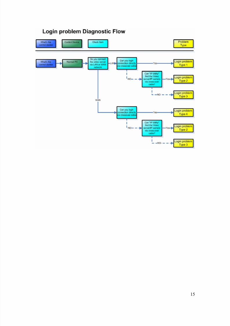
4-1 Find out the possible cause
Please refer to the diagnostic flow to find out the problem type of the Login
Problem.
Then you can refer to next section for advanced clarification and
troubleshooting.
Check Item Remark
Step1 Check the Control Device
Step2 Connect the PC directly to the Video
server/Transcoder then via cross-over cable.
Then input the Video server/Transcoder to see
if you can connect?
Please connect to LAN or
WAN you used to connect
previously
Step3 Refer to the section of each problem type to do
root cause clarification and find respective
solutions.
8/21/2019 IP Surveillance TroubleShooting Guide_V0.9
http://slidepdf.com/reader/full/ip-surveillance-troubleshooting-guidev09 17/347
15
8/21/2019 IP Surveillance TroubleShooting Guide_V0.9
http://slidepdf.com/reader/full/ip-surveillance-troubleshooting-guidev09 18/347
16
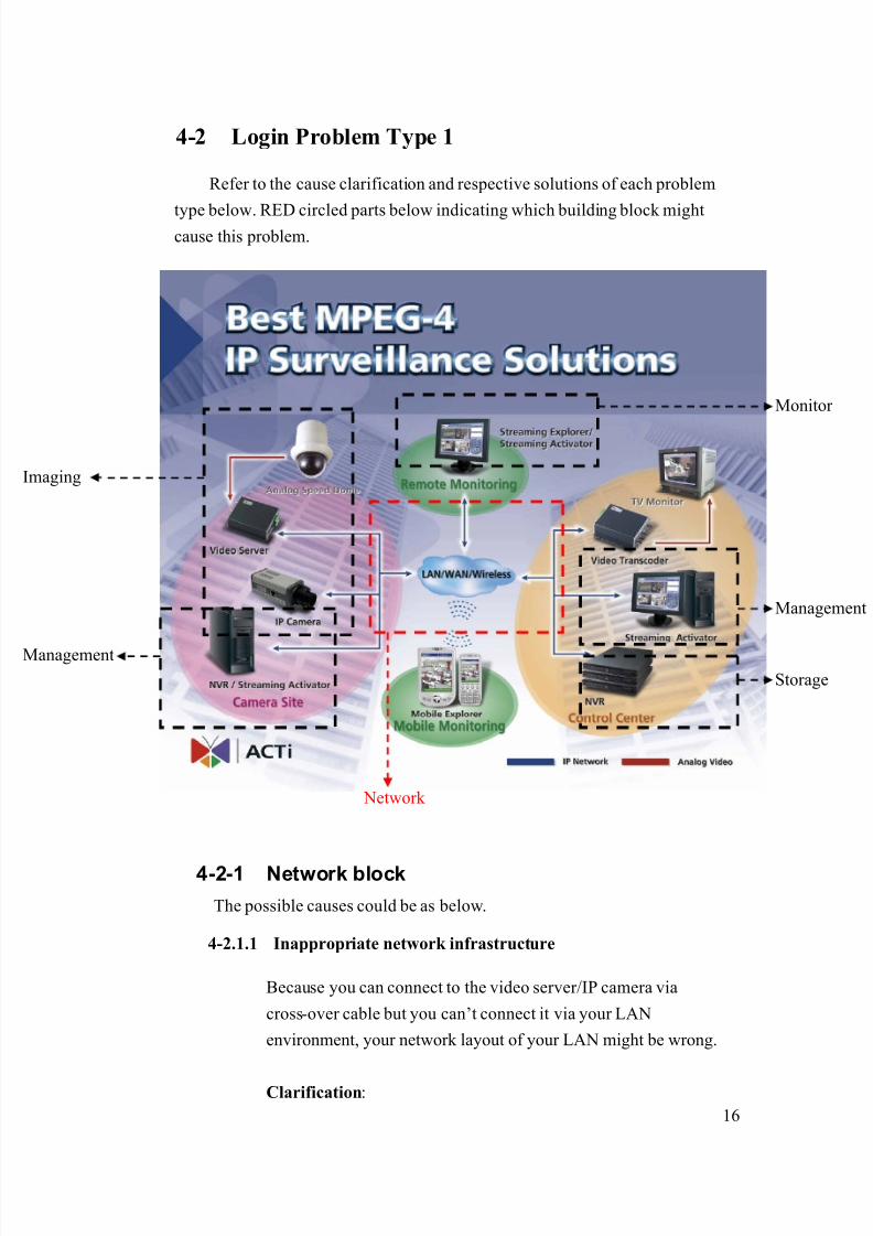
4-2 Login Problem Type 1
Refer to the cause clarification and respective solutions of each problem
type below. RED circled parts below indicating which building block mightcause this problem.
4-2-1 Network block
The possible causes could be as below.
4-2.1.1 Inappropriate network infrastructure
Because you can connect to the video server/IP camera via
cross-over cable but you can’t connect it via your LAN
environment, your network layout of your LAN might be wrong.
Clarification:
Network
Management
Storage
maging
Monitor
Management
8/21/2019 IP Surveillance TroubleShooting Guide_V0.9
http://slidepdf.com/reader/full/ip-surveillance-troubleshooting-guidev09 19/347
17
1. Connect the PC and Video Server back to original LAN
2. Use the PC to ping the Video Server’s IP address
3. The ping is likely to fail.
Solution:
1. Contact your MIS or anyone that build your network
infrastructure.
2. Give him the test report above and ask him to fix the ping
fail problem.
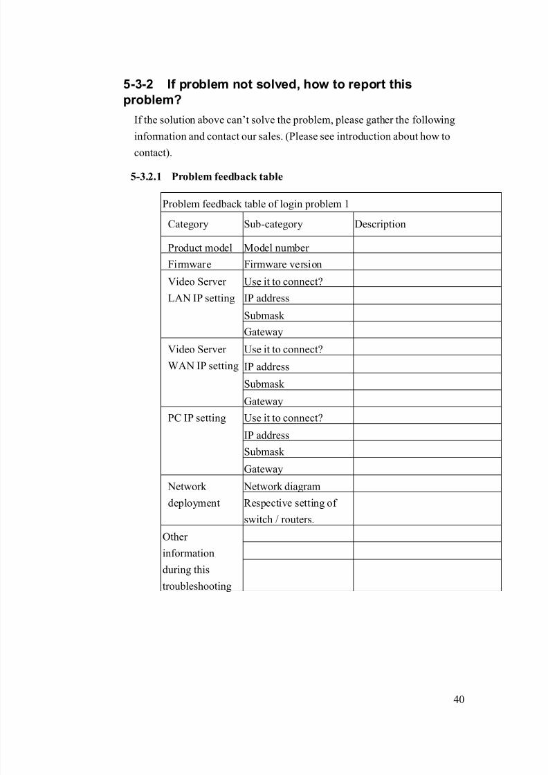
4-2-2 If problem not solved, how to report this
problem?
If the solution above can’t solve the problem, please gather the following
information and contact our sales. (Please see introduction about how to
contact).
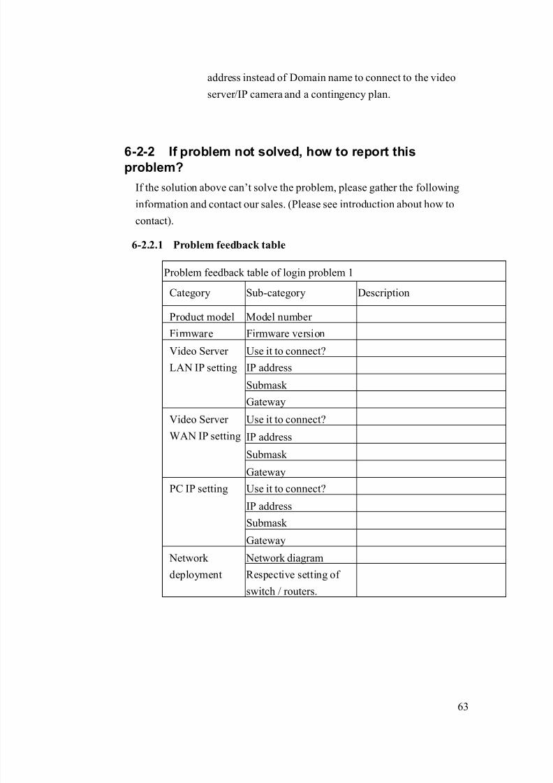
4-2.2.1 Problem feedback table
Problem feedback table of login problem 1
Category Sub-category Description
Product model Model number
Firmware Firmware version
Use it to connect?
IP address
Submask
Video Server
LAN IP setting
Gateway
Use it to connect?
IP address
Submask
Video Server
WAN IP setting
Gateway
Use it to connect?
IP address
Submask
PC IP setting
Gateway
Network diagram Network
deployment Respective setting of
switch / routers.

8/21/2019 IP Surveillance TroubleShooting Guide_V0.9
http://slidepdf.com/reader/full/ip-surveillance-troubleshooting-guidev09 20/347
18
4-3 Login Problem Type 2
Refer to the cause clarification and respective solutions of each problem
type below. RED circled parts below indicating which building block mightcause this problem.
4-3-1 Network block
The possible causes could be as below
4-3.1.1 Inappropriate Video server/IP camera IP address setting
Sometimes you can’t link to the video server /IP camera It could be
caused by the video server/IP camera IP address. This setting is
relevant to PC’s IP address and Subnet mask setting. Then we will
discuss both of them in this section.
Network
Management
Storage
maging
Monitor
Management
8/21/2019 IP Surveillance TroubleShooting Guide_V0.9
http://slidepdf.com/reader/full/ip-surveillance-troubleshooting-guidev09 21/347
19
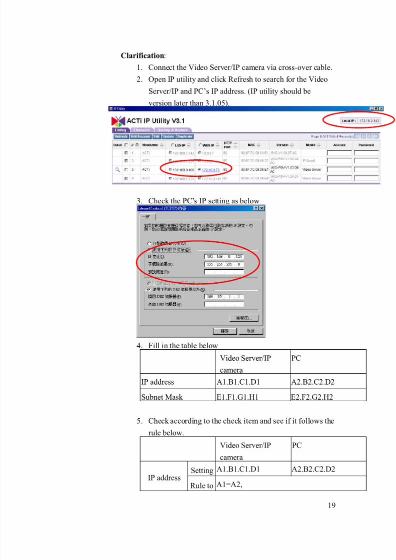
Clarification:
1. Connect the Video Server/IP camera via cross-over cable.
2. Open IP utility and click Refresh to search for the Video
Server/IP and PC’s IP address. (IP utility should be
version later than 3.1.05).
3. Check the PC’s IP setting as below
4. Fill in the table below
Video Server/IP
camera
PC
IP address A1.B1.C1.D1 A2.B2.C2.D2
Subnet Mask E1.F1.G1.H1 E2.F2.G2.H2
5. Check according to the check item and see if it follows the
rule below.
Video Server/IP
camera
PC
Setting A1.B1.C1.D1 A2.B2.C2.D2IP address
Rule to A1=A2,
8/21/2019 IP Surveillance TroubleShooting Guide_V0.9
http://slidepdf.com/reader/full/ip-surveillance-troubleshooting-guidev09 22/347
20
check B1=B2,
C1=C2,
D1≠D2
Setting E1.F1.G1.H1 E2.F2.G2.H2
Subnet Mask Rule to
Check
E1=E2=255,
F1=F2=255,
G1=G2=255,
H1=H2=0
6. If yes, this is not IP address setting.
7. If not, please follow the solution as below.
Solution:
1. Follow the rule below to change the PC setting.
Video Server/IP
camera
PC
Setting A1.B1.C1.D1 A2.B2.C2.D2
IP address Rule to
check
A1=A2,
B1=B2,
C1=C2,
D1≠D2
Setting E1.F1.G1.H1 E2.F2.G2.H2
Subnet Mask Rule to
Check
E1=E2=255,
F1=F2=255,
G1=G2=255,
H1=H2=0
2. After change the PC setting, try connecting to the video
server/IP camera again.
4-3.1.2 Wrong PC IP address setting
This site is included in the previous section 4-3.1.1. Please go there
and see details.
8/21/2019 IP Surveillance TroubleShooting Guide_V0.9
http://slidepdf.com/reader/full/ip-surveillance-troubleshooting-guidev09 23/347
21
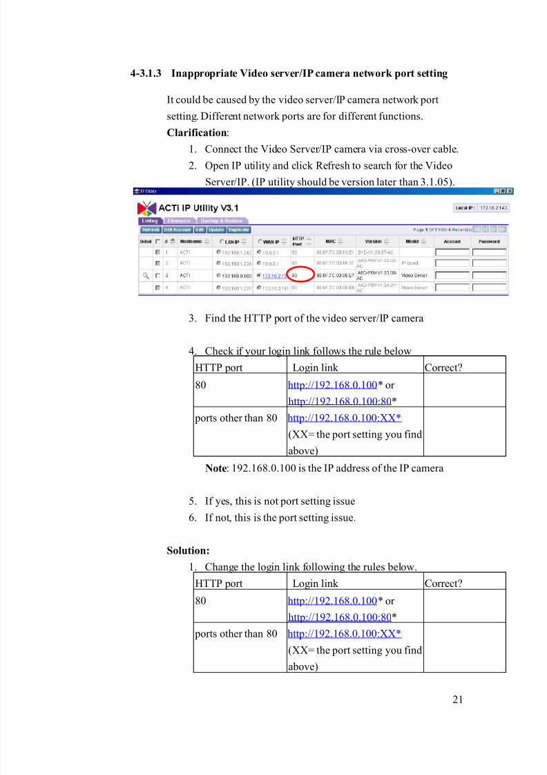
4-3.1.3 Inappropriate Video server/IP camera network port setting
It could be caused by the video server/IP camera network port
setting. Different network ports are for different functions.
Clarification:1. Connect the Video Server/IP camera via cross-over cable.
2. Open IP utility and click Refresh to search for the Video
Server/IP. (IP utility should be version later than 3.1.05).
3. Find the HTTP port of the video server/IP camera
4. Check if your login link follows the rule below
HTTP port Login link Correct?
80 http://192.168.0.100* or
http://192.168.0.100:80*
ports other than 80 http://192.168.0.100:XX*
(XX= the port setting you find
above)
Note: 192.168.0.100 is the IP address of the IP camera
5. If yes, this is not port setting issue
6. If not, this is the port setting issue.
Solution:
1. Change the login link following the rules below.
HTTP port Login link Correct?
80 http://192.168.0.100* or
http://192.168.0.100:80*
ports other than 80 http://192.168.0.100:XX*
(XX= the port setting you find
above)

8/21/2019 IP Surveillance TroubleShooting Guide_V0.9
http://slidepdf.com/reader/full/ip-surveillance-troubleshooting-guidev09 24/347
22
4-3-2 Monitoring block
The possible causes could be as below
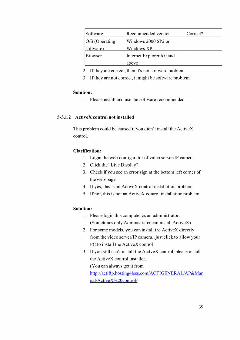
4-3.2.1 Inappropriate O/S and Browser software
The possible cause might be the browser software you use to login
the video server/IP camera.
Clarification:
1. Check if your software
Software Recommended version Correct?
O/S (Operating
software)
Windows 2000 SP2 or
Window XP
Browser Internet Explorer 6.0 and
above
2. If they are correct, then it’s not software problem
3. If they are not correct, it might be software problem
Solution:
1. Please install and use the software recommended.
4-3.2.2 Wrong ID and password
The login might fail if you input the wrong account ID and
password.
Clarification:
1. ID and password is captive sensitive, please make sure
that you are inputting the right one.
Default ID: Admin (captive sensitive)Default Password: 123456
Solution:
1. If you can’t recall the ID and password, please “Hardware
reset” the camera. (See respective hardware user manual).
2. Then login with the default ID and password
Default ID: Admin (captive sensitive)
Default Password: 123456
8/21/2019 IP Surveillance TroubleShooting Guide_V0.9
http://slidepdf.com/reader/full/ip-surveillance-troubleshooting-guidev09 25/347
23
4-3-3 If problem not solved, how to report this
problem?
If the solution above can’t solve the problem, please gather the following
information and contact our sales. (Please see introduction about how to
contact).
4-3.3.1 Problem feedback table
Problem feedback table of login problem 1
Category Sub-category Description
Product model Model number
Firmware Firmware version
Other information you
found during the
testing

8/21/2019 IP Surveillance TroubleShooting Guide_V0.9
http://slidepdf.com/reader/full/ip-surveillance-troubleshooting-guidev09 26/347
24
4-4 Login Problem Type 3
Refer to the cause clarification and respective solutions of each problem
type below. RED circled parts below indicating which building block mightcause this problem.
4-4-1 Imaging block
The possible causes could be as below
4-4.1.1 Inappropriate network physical connection
It might because of the physical connection error (such as network
cable fail, or cabling wrong).
Clarification:
1. Connect your Video server/IP camera to a switch via the
network cable you are using.
Network
Management
Storage
maging
Monitor
Management
8/21/2019 IP Surveillance TroubleShooting Guide_V0.9
http://slidepdf.com/reader/full/ip-surveillance-troubleshooting-guidev09 27/347
25
2. Check if the Network LED on Video Server and Switch
on?
3. If both are on, then is it not physical connection problem
4. If any of those are not, the physical connection is wrong.
Solution:
1. If the Video Server/IP camera is using standard RJ-45
network connector, just replace with a new cable.
2. If the Video Server/IP camera is not using standard RJ-45
connector (ex: CAM-5130/CAM-5140/CAM-5150),
please use follow the user manual of
CAM-5130/CAM-5140/CAM-5150 and make new cable
if necessary?
4-4.1.2 Inappropriate network platform – temporally failure
The network platform very rarely might fail for unknown reason.
Clarification:
1. Please reboot the camera.
2. Check if you can find the camera afterward.
3. If yes, this is a network platform temporally failure problem
4. If not, this is not a network platform temporally failure
problem
Solution:
1. Because the network platform is very rarely to fail, you
can go on use it. But if your system temporally fails too
often, please contact our sales.
4-4-2 If problem not solved, how to report thisproblem?
If the solution above can’t solve the problem, please gather the following
information and contact our sales. (Please see introduction about how to
contact).

8/21/2019 IP Surveillance TroubleShooting Guide_V0.9
http://slidepdf.com/reader/full/ip-surveillance-troubleshooting-guidev09 28/347
26
4-4.2.1 Problem feedback table
Problem feedback table of login problem 1
Category Sub-category Description
Product model Model number
Other
information you
found during the
testing
8/21/2019 IP Surveillance TroubleShooting Guide_V0.9
http://slidepdf.com/reader/full/ip-surveillance-troubleshooting-guidev09 29/347
27
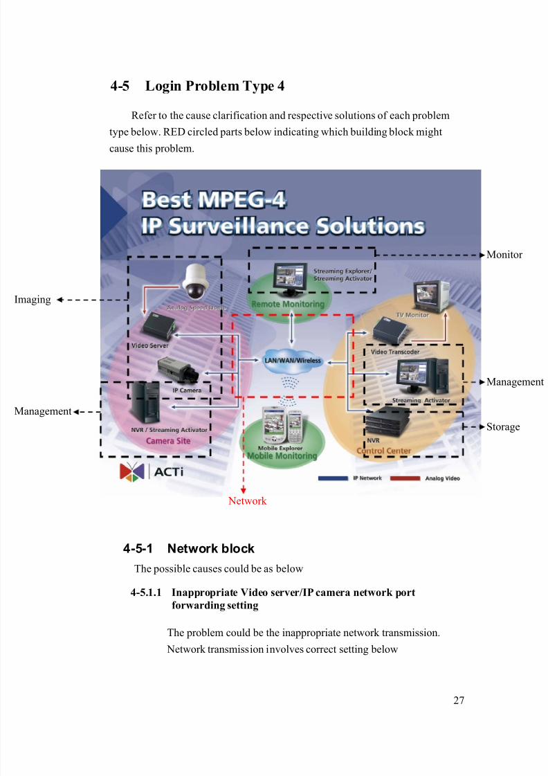
4-5 Login Problem Type 4
Refer to the cause clarification and respective solutions of each problem
type below. RED circled parts below indicating which building block mightcause this problem.
4-5-1 Network block
The possible causes could be as below
4-5.1.1 Inappropriate Video server/IP camera network port
forwarding setting
The problem could be the inappropriate network transmission.
Network transmission involves correct setting below
Network
Management
Storage
maging
Monitor
Management

8/21/2019 IP Surveillance TroubleShooting Guide_V0.9
http://slidepdf.com/reader/full/ip-surveillance-troubleshooting-guidev09 30/347
28
Network transmission check table
Category Sub-category
Internet connectivityVideo Server
Port setting
Port forwarding Network
Firewall setting
PC Internet connectivity
Because each parts are dependent to each other. Then we put them
all together in this section.
Clarification:
1. Please read the support package TS-00009 attached.
- Chapter 1~3: How does internet communication works
- Appendix C : How to check the network
communication
2. If the check fails, this is a network communication
problem.
3. If the check ok, this is not a network communication problem.
Solution:
1. Follows the support package TS-00009 to build up the
internet communication step by step. .
4-5.1.2 Inappropriate network port setting
The problem is discussed in 4-5.1.1, please go there for details.
4-5.1.3 Video server/IP camera has no internet connectivity
The problem is discussed in 4-5.1.1, please go there for details.
8/21/2019 IP Surveillance TroubleShooting Guide_V0.9
http://slidepdf.com/reader/full/ip-surveillance-troubleshooting-guidev09 31/347
29
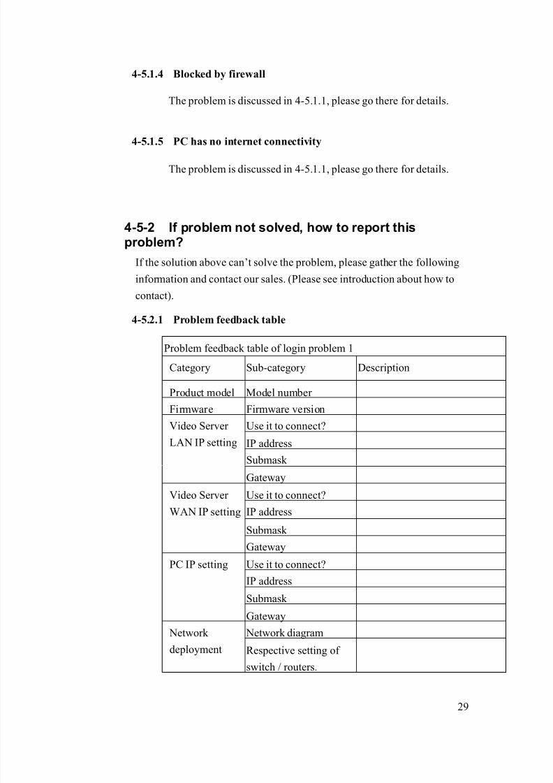
4-5.1.4 Blocked by firewall
The problem is discussed in 4-5.1.1, please go there for details.
4-5.1.5 PC has no internet connectivity
The problem is discussed in 4-5.1.1, please go there for details.
4-5-2 If problem not solved, how to report thisproblem?
If the solution above can’t solve the problem, please gather the following
information and contact our sales. (Please see introduction about how to
contact).
4-5.2.1 Problem feedback table
Problem feedback table of login problem 1
Category Sub-category Description
Product model Model number
Firmware Firmware versionUse it to connect?
IP address
Submask
Video Server
LAN IP setting
Gateway
Use it to connect?
IP address
Submask
Video Server
WAN IP setting
GatewayUse it to connect?
IP address
Submask
PC IP setting
Gateway
Network diagram Network
deployment Respective setting of
switch / routers.

8/21/2019 IP Surveillance TroubleShooting Guide_V0.9
http://slidepdf.com/reader/full/ip-surveillance-troubleshooting-guidev09 32/347
30
8/21/2019 IP Surveillance TroubleShooting Guide_V0.9
http://slidepdf.com/reader/full/ip-surveillance-troubleshooting-guidev09 33/347
31
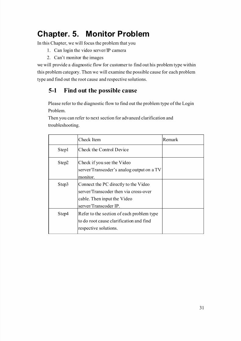
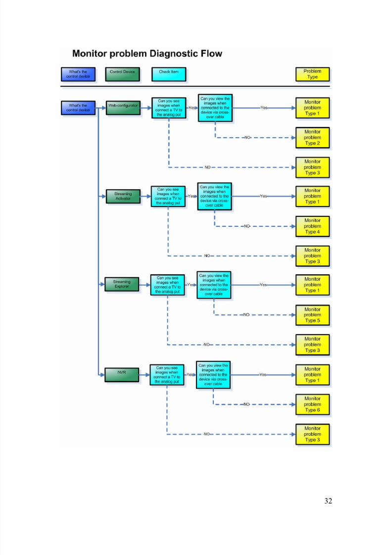
Chapter. 5. Monitor ProblemIn this Chapter, we will focus the problem that you
1. Can login the video server/IP camera
2. Can’t monitor the imageswe will provide a diagnostic flow for customer to find out his problem type within
this problem category. Then we will examine the possible cause for each problem
type and find out the root cause and respective solutions.
5-1 Find out the possible cause
Please refer to the diagnostic flow to find out the problem type of the Login
Problem.
Then you can refer to next section for advanced clarification andtroubleshooting.
Check Item Remark
Step1 Check the Control Device
Step2 Check if you see the Video
server/Transcoder’s analog output on a TV
monitor.Step3 Connect the PC directly to the Video
server/Transcoder then via cross-over
cable. Then input the Video
server/Transcoder IP.
Step4 Refer to the section of each problem type
to do root cause clarification and find
respective solutions.
8/21/2019 IP Surveillance TroubleShooting Guide_V0.9
http://slidepdf.com/reader/full/ip-surveillance-troubleshooting-guidev09 34/347
32
8/21/2019 IP Surveillance TroubleShooting Guide_V0.9
http://slidepdf.com/reader/full/ip-surveillance-troubleshooting-guidev09 35/347
33
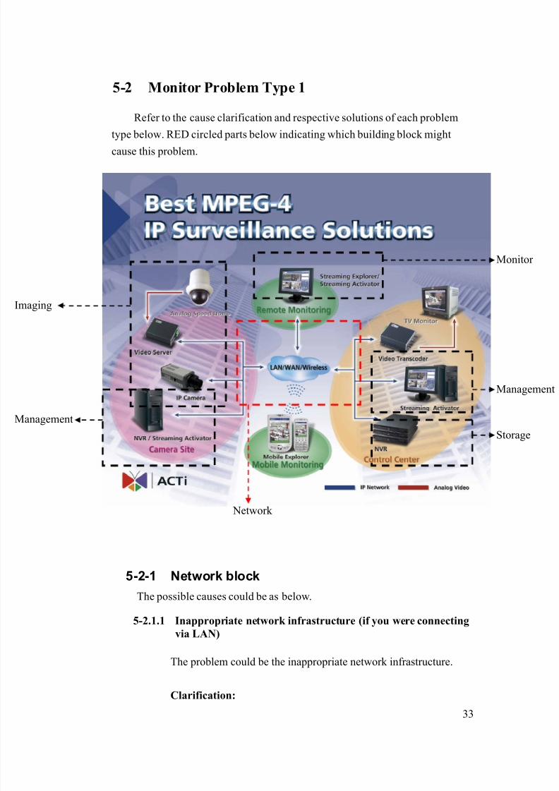
5-2 Monitor Problem Type 1
Refer to the cause clarification and respective solutions of each problem
type below. RED circled parts below indicating which building block mightcause this problem.
5-2-1 Network block
The possible causes could be as below.
5-2.1.1 Inappropriate network infrastructure (if you were connecting
via LAN)
The problem could be the inappropriate network infrastructure.
Clarification:
Network
Management
Storage
maging
Monitor
Management

8/21/2019 IP Surveillance TroubleShooting Guide_V0.9
http://slidepdf.com/reader/full/ip-surveillance-troubleshooting-guidev09 36/347
34
1. Below is the status of this problem definition so far.
Network
environment Respective network ports
Function
Cross-over LAN Port name Port number
(Default)
Login Yes Yes HTTP 80
HTTP 80
Register 6000
View image Yes No
Streaming 6002
2. As you can see from the table, there’s something wrong
about your LAN.
Solution:
1. Because this problem involves mostly about your LAN
environment, it’s less possible for us to provide the
solution.
2. Please fill in your definition table
Network
environment Respective network ports
Function
Cross-over LAN Port name Port number
Login Yes Yes HTTP
HTTP
Register
View image Yes No
Streaming
3. Please provide the definition table above to your MIS or
your network architect for this problem. Ask him for
solution.

8/21/2019 IP Surveillance TroubleShooting Guide_V0.9
http://slidepdf.com/reader/full/ip-surveillance-troubleshooting-guidev09 37/347
35
5-2.1.2 Inappropriate network port forwarding (if you wereconnecting via WAN)
The problem could be the inappropriate network transmission.
Network transmission involves correct setting below. Then we put
them all together.
Network transmission check table
Category Sub-category
Internet connectivityVideo Server
Port setting
Port forwarding Network
Firewall setting
PC Internet connectivity
Clarification:
1. Below is the status of this problem definition so far.
Network environment
Respective network ports
Function
Cross-over WAN Port name Port number
(Default)
Login Yes Yes HTTP 80
HTTP 80
Register 6000
Monitor Yes No
Streaming 6002
2. As you can see from the table, there’s something wrong
about your WAN.
4. Please read the support package TS-00009 attached.
- Chapter 1~3: How does internet communication works
- Appendix C : How to check the network
communication for Monitoring images
5. If the check fails, this is a network communication
problem.
6. If the check ok, this is not a network communication
8/21/2019 IP Surveillance TroubleShooting Guide_V0.9
http://slidepdf.com/reader/full/ip-surveillance-troubleshooting-guidev09 38/347
36
problem.
Solution:
2. Follows the support package TS-00009 to build up the
internet communication step by step. .
5-2.1.3 Blocked by firewall (if you were connecting via WAN)
The problem is discussed in 4-5.1.1, please go there for details.
5-2.1.4 DNS problem (if you were connecting via DNS)
This problem could happen if you connect to the video server/IP
camera using Domain Name (Ex: http://myroom.dyndns.org)
instead of IP address (Ex: http://59.233.23.59).
Clarification:
1. Please switch the software setting from IP address from
Domain Name to IP address and see if you can monitor
the images.
2. If yes, this is a DNS problem.
3. If not, this is not a DNS problem.
Solution:
1. Report the following information to our sales. We will
provide you an updated version A.S.A.P.
Category Description Example:
Hardware
Model number
SED-2120
Firmware
version
A1D-V2.00.00
Software model NVR
Software
version
V1.00.00
2. Before you get that updated version, you can use IP
address instead of Domain name to connect to the video
8/21/2019 IP Surveillance TroubleShooting Guide_V0.9
http://slidepdf.com/reader/full/ip-surveillance-troubleshooting-guidev09 39/347
37
server/IP camera and a contingency plan.
5-2-2 If problem not solved, how to report this
problem?If the solution above can’t solve the problem, please gather the following
information and contact our sales. (Please see introduction about how to
contact).
5-2.2.1 Problem feedback table
Problem feedback table of login problem 1
Category Sub-category Description
Product model Model number
Firmware Firmware version
Use it to connect?
IP address
Submask
Video Server
LAN IP setting
Gateway
Use it to connect?
IP address
Submask
Video Server
WAN IP setting
Gateway
Use it to connect?
IP address
Submask
PC IP setting
Gateway
Network diagram Network
deployment Respective setting of
switch / routers.
Model
Version
Software
Setting

8/21/2019 IP Surveillance TroubleShooting Guide_V0.9
http://slidepdf.com/reader/full/ip-surveillance-troubleshooting-guidev09 40/347
38
5-3 Monitor Problem Type 2
Refer to the cause clarification and respective solutions of each problem
type below. RED circled parts below indicating which building block mightcause this problem.
5-3-1 Monitor block
The possible causes could be as below.
5-3.1.1 Inappropriate O/S and Browser software
The possible cause might be the browser software you use to login
the video server/IP camera.
Clarification:
1. Check if your software
Network
Management
Storage
maging
Monitor
Management
Management
Storage
Monitor
Management
8/21/2019 IP Surveillance TroubleShooting Guide_V0.9
http://slidepdf.com/reader/full/ip-surveillance-troubleshooting-guidev09 41/347
39
Software Recommended version Correct?
O/S (Operating
software)
Windows 2000 SP2 or
Windows XP
Browser Internet Explorer 6.0 and
above
2. If they are correct, then it’s not software problem
3. If they are not correct, it might be software problem
Solution:
1. Please install and use the software recommended.
5-3.1.2 ActiveX control not installed
This problem could be caused if you didn’t install the ActiveX
control.
Clarification:
1. Login the web-configurator of video server/IP camera
2. Click the “Live Display”
3. Check if you see an error sign at the bottom left corner of
the web-page.
4. If yes, this is an ActiveX control installation problem
5. If not, this is not an ActiveX control installation problem
Solution:
1. Please login this computer as an administrator.
(Sometimes only Administrator can install ActiveX)
2. For some models, you can install the ActiveX directly
from the video server/IP camera., just click to allow your PC to install the ActiveX control
3. If you still can’t install the AcitveX control, please install
the ActiveX control installer.
(You can always get it from
http://actiftp.hosting4less.com/ACTIGENERAL/AP&Man
ual/ActiveX%20control/)
8/21/2019 IP Surveillance TroubleShooting Guide_V0.9
http://slidepdf.com/reader/full/ip-surveillance-troubleshooting-guidev09 42/347
40
5-3-2 If problem not solved, how to report this
problem?
If the solution above can’t solve the problem, please gather the following
information and contact our sales. (Please see introduction about how to
contact).
5-3.2.1 Problem feedback table
Problem feedback table of login problem 1
Category Sub-category Description
Product model Model number
Firmware Firmware version
Use it to connect?
IP address
Submask
Video Server
LAN IP setting
Gateway
Use it to connect?
IP address
Submask
Video Server
WAN IP setting
Gateway
Use it to connect?
IP address
Submask
PC IP setting
Gateway
Network diagram Network
deployment Respective setting of
switch / routers.
Other
information
during this
troubleshooting

8/21/2019 IP Surveillance TroubleShooting Guide_V0.9
http://slidepdf.com/reader/full/ip-surveillance-troubleshooting-guidev09 43/347
41
5-4 Monitor Problem Type 3
Refer to the cause clarification and respective solutions of each problem
type below. RED circled parts below indicating which building block mightcause this problem.
5-4-1 Image
The possible causes could be as below.
5-4.1.1 Analog Video- Lens problem
This could be the lens problem that caused no lighting income to
the camera. This problem happens on BOX camera which requires
you to install a lens onto it.
Network
Management
Storage
maging
Monitor
Management

8/21/2019 IP Surveillance TroubleShooting Guide_V0.9
http://slidepdf.com/reader/full/ip-surveillance-troubleshooting-guidev09 44/347
42
Clarification:
1. Remove the lens
2. See if the image become white
3. If yes, this is the lens problem
4. If not, this is not the lens problem
Solution:
1. The solution varies for different kind of lens you use.
Please follow the table below for solutions.
Lens type Solution steps
1 Check if there’s anything
blocking the lens (ex: lens cover)
2 Be sure to connect the “Auto Iris”
Cable to the camera
Auto-Iris
3 Be sure to switch the camera
setting to “Auto Iris” or “DC Iris”
1 Check if there’s anything
blocking the lens (ex: lens cover)
Fixed Iris
2 Be sure to switch the camera
setting to “AES”
5-4.1.2 Analog Video- Camera power up fail
This could be the camera power up fail.
Clarification:
The clarification procedure different for different kinds of
camera, please see below table for details.Camera Type Clarification procedure
Zoom Lens
camera
1. Reboot the camera
2. See if the zoom lens moves during start-up (It
moves as if it wants to zoom-in then zoom-out)
3. If yes, this is a temporally camera power up
problem

8/21/2019 IP Surveillance TroubleShooting Guide_V0.9
http://slidepdf.com/reader/full/ip-surveillance-troubleshooting-guidev09 45/347
43
4. If not, this is the a camera power up problem
Speed dome or
PTZ camera
1. Reboot the camera
2. See if the camera initialize during start-up (it
will pan, tilt and zoom)3. If yes, this is a temporally camera power up
problem
4. If not, this is a camera power up problem
Other cameras
(Not zoom lens
or speed dome
or PTZ camera)
1. Reboot the camera
2. See if the image becomes ok
3. If yes, this is a temporally camera power up
problem
4. If not, this might be a camera power up
problem. Please check other possible cause first.
If you can’t find other possible cause, then we
can think it as a camera power up problem.
Solution:
1. The solution varies for different kind situation. Please see
the table below for respective solutions.
Power up problem
type
Solution steps
1 Normally, this problem happens
rarely. You can just ignore this
problem.
Temporally power up
problem
2 If the problem happens very often,
please gather problem information
and contact our sales.
Power up problem 1 If the problem happens very often,
please gather problem information
and contact our sales.
5-4.1.3 Analog Video- BNC wiring fail
It happens only when you are using a video server connecting to an
analog camera. This could be the camera’s BNC wiring fail that
8/21/2019 IP Surveillance TroubleShooting Guide_V0.9
http://slidepdf.com/reader/full/ip-surveillance-troubleshooting-guidev09 46/347
44
causes the video server receive no video signal
Clarification:
1. Get a BNC cable from a working system (a BNC cable
that works fine)
2. Connect the Video server to the IP camera via the BNC
cable and see if you can see the image via analog output
3. If yes, this is the BNC wiring problem.
4. If not, this is not the BNC wiring problem
Solution:
1. Simply replace current BNC cable with a working one.
5-4.1.4 Analog Video- DC level adjust
It happens for IP camera or analog camera with DC level adjusts. If
the DC level is set to very low, the image will be completely dark.
That is because the DC level directly affects the brightness of the
camera.
Clarification:
1. Increase the DC level according to the hardware manual
2. See if the images is ok
3. If yes, this is DC level problem
4. If not, this is not DC level problem
Solution:
1. Adjust the DC level according to your environment. .
8/21/2019 IP Surveillance TroubleShooting Guide_V0.9
http://slidepdf.com/reader/full/ip-surveillance-troubleshooting-guidev09 47/347
45
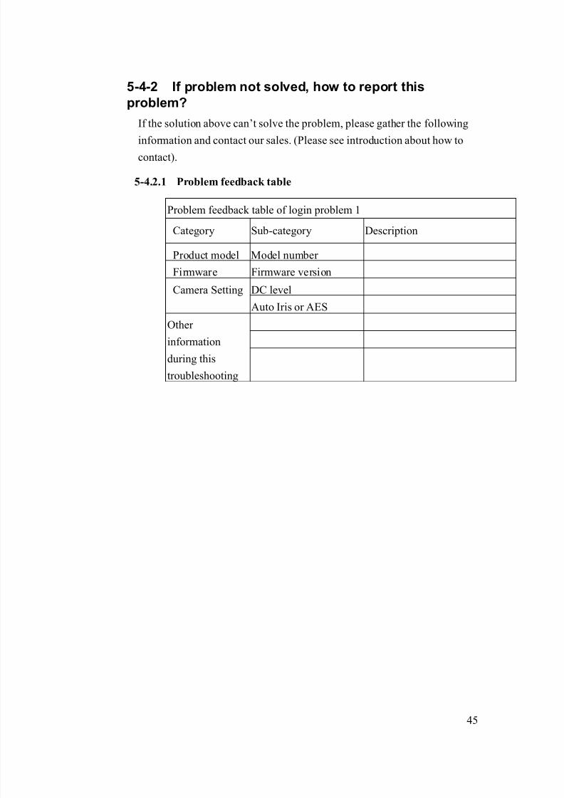
5-4-2 If problem not solved, how to report this
problem?
If the solution above can’t solve the problem, please gather the following
information and contact our sales. (Please see introduction about how to
contact).
5-4.2.1 Problem feedback table
Problem feedback table of login problem 1
Category Sub-category Description
Product model Model number
Firmware Firmware version
DC levelCamera Setting
Auto Iris or AES
Other
information
during this
troubleshooting
8/21/2019 IP Surveillance TroubleShooting Guide_V0.9
http://slidepdf.com/reader/full/ip-surveillance-troubleshooting-guidev09 48/347
46
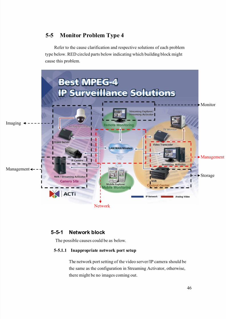
5-5 Monitor Problem Type 4
Refer to the cause clarification and respective solutions of each problem
type below. RED circled parts below indicating which building block mightcause this problem.
5-5-1 Network block
The possible causes could be as below.
5-5.1.1 Inappropriate network port setup
The network port setting of the video server/IP camera should be
the same as the configuration in Streaming Activator, otherwise,
there might be no images coming out.
Network
Management
Storage
maging
Monitor
Management

8/21/2019 IP Surveillance TroubleShooting Guide_V0.9
http://slidepdf.com/reader/full/ip-surveillance-troubleshooting-guidev09 49/347
47
Clarification:
1. Login the camera and open streaming Activator to fill in
the port setting table below.
FunctionPort
Function
Video
Server/IP
camera
Streaming
Activator Default value
HTTP 80
Register 6000
Monitor
Streaming 6002
2. Check each function port and see if it is the same in both
video server/IP camera and the Streaming Activator
(below is a reference result)
FunctionPort
Function
Video
Server/IP
camera
Streaming
Activator The same?
HTTP 80 80 Yes
Register 6000 7000 NO
Monitor
Streaming 6002 7002 NO
3. If any of those are not the same, this is a port setting
problem.
4. If all these port setting are the same, this is not a port
setting problem.
Solution:
1. Adjust the setting of the streaming activator or video
server/IP camera to make the port setting is the same for
each port.
Example:
FunctionPort
Function
Video
Server/IP
camera
Streaming
Activator The same?
HTTP 80 80 YesMonitor
Register 6000 7000 Yes

8/21/2019 IP Surveillance TroubleShooting Guide_V0.9
http://slidepdf.com/reader/full/ip-surveillance-troubleshooting-guidev09 50/347
48
->6000
Streaming 6002 7002
->6002
Yes
5-5-2 Management block
The possible causes could be as below.
5-5.2.1 Inappropriate Streaming Activator version
For some previous Streaming Activator version, it doesn’t support
all our IP cameras. Then it could cause the monitor to fail.
Clarification:
1. Check the table below to see if it is a Streaming Activator
version problem
Video Server/IP camera Protocol version*Streaming
Activator version
TCP1.0* TCP2.0*
Version before
1.36.00.00OK OK Fail Fail
Version after
1.36.00.00OK OK OK OK
Note: Please refer to the support package TS-00104
- Firmware function comparison table of TCP1.0
and TCP2.0
- TCP2.0 and TCP1.0 supporting product list.
Note: For TCP1.0 and TCP2.0, please also make sure the
firmware version as below
- TCP1.0 : The firmware function should be after
1.03.02
- TCP2.0 : The firmware and TCP1.0 supporting
product list.
2. If your using environment is in the grey area above, this is
a Streaming Activator version problem.
8/21/2019 IP Surveillance TroubleShooting Guide_V0.9
http://slidepdf.com/reader/full/ip-surveillance-troubleshooting-guidev09 51/347
49
Solution:
1. Please go to our website to download the newest
Streaming Activator software
http://www.acti.com/support/support_index.asp
5-5-3 If problem not solved, how to report this
problem?
If the solution above can’t solve the problem, please gather the following
information and contact our sales. (Please see introduction about how to
contact).
5-5.3.1 Problem feedback table
Problem feedback table of login problem 1
Category Sub-category Description
Hard model Model number
Firmware Firmware version
Software model Use it to connect?
Softwareversion
Use it to connect?
IP address
Submask
Video Server
LAN IP setting
Gateway
Use it to connect?
IP address
Submask
Video Server
WAN IP setting
Gateway
Use it to connect?
IP address
Submask
PC IP setting
Gateway
8/21/2019 IP Surveillance TroubleShooting Guide_V0.9
http://slidepdf.com/reader/full/ip-surveillance-troubleshooting-guidev09 52/347
50
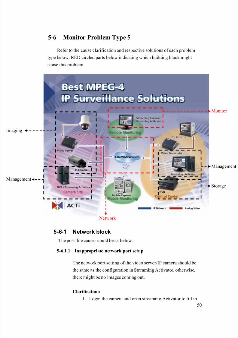
5-6 Monitor Problem Type 5
Refer to the cause clarification and respective solutions of each problem
type below. RED circled parts below indicating which building block mightcause this problem.
5-6-1 Network block
The possible causes could be as below.
5-6.1.1 Inappropriate network port setup
The network port setting of the video server/IP camera should be
the same as the configuration in Streaming Activator, otherwise,
there might be no images coming out.
Clarification:
1. Login the camera and open streaming Activator to fill in
Network
Management
Storage
maging
Monitor
Management

8/21/2019 IP Surveillance TroubleShooting Guide_V0.9
http://slidepdf.com/reader/full/ip-surveillance-troubleshooting-guidev09 53/347
51
the port setting table below.
FunctionPort
Function
Video
Server/IP
camera
Streaming
Activator Default value
HTTP 80
Register 6000
Monitor
Streaming 6002
2. Check each function port and see if it is the same in both
video server/IP camera and the Streaming Activator
(below is a reference result)
FunctionPort
Function
Video
Server/IP
camera
Streaming
Activator The same?
HTTP 80 80 Yes
Register 6000 7000 NO
Monitor
Streaming 6002 7002 NO
3. If any of those are not the same, this is a port setting
problem.
4. If all these port setting are the same, this is not a port
setting problem.
Solution:
1. Adjust the setting of the streaming activator or video
server/IP camera to make the port setting is the same for
each port.
Example:
FunctionPort
Function
Video
Server/IP
camera
Streaming
Activator The same?
HTTP 80 80 Yes
Register 6000 7000
->6000
Yes
Monitor
Streaming 6002 7002 Yes
8/21/2019 IP Surveillance TroubleShooting Guide_V0.9
http://slidepdf.com/reader/full/ip-surveillance-troubleshooting-guidev09 54/347
52
->6002
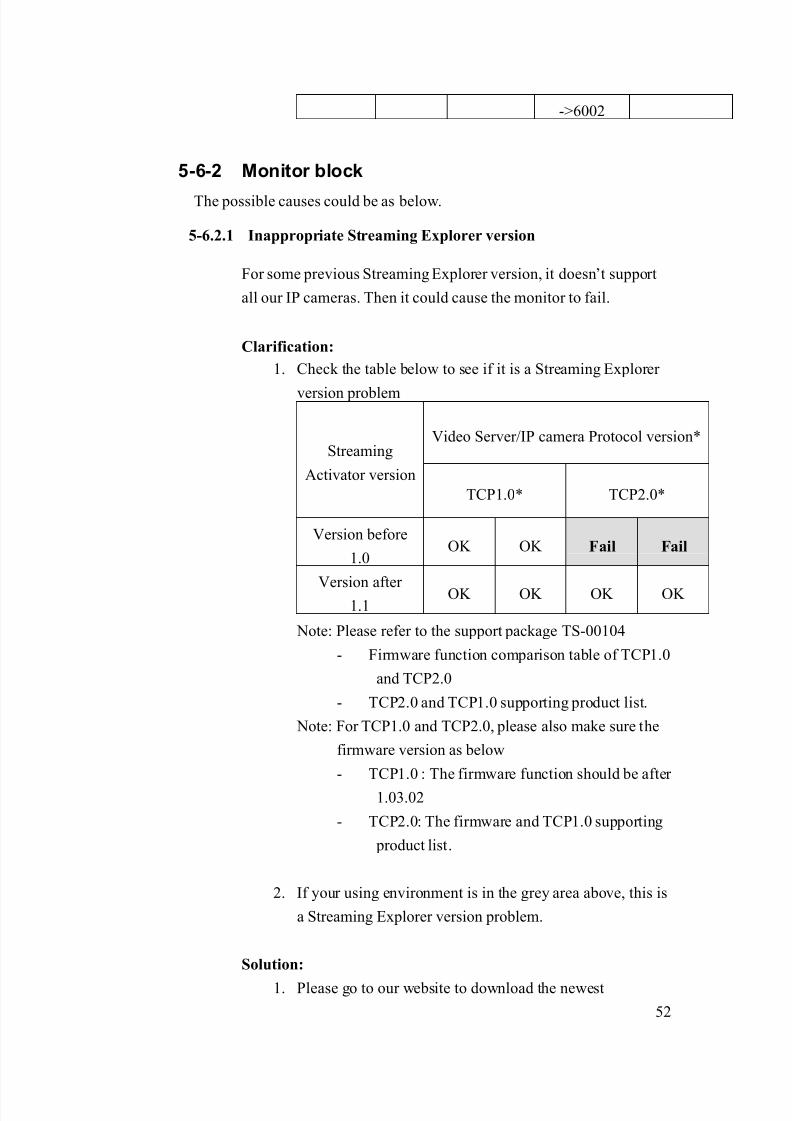
5-6-2 Monitor block
The possible causes could be as below.
5-6.2.1 Inappropriate Streaming Explorer version
For some previous Streaming Explorer version, it doesn’t support
all our IP cameras. Then it could cause the monitor to fail.
Clarification:
1. Check the table below to see if it is a Streaming Explorer
version problem
Video Server/IP camera Protocol version*Streaming
Activator version
TCP1.0* TCP2.0*
Version before
1.0OK OK Fail Fail
Version after 1.1
OK OK OK OK
Note: Please refer to the support package TS-00104
- Firmware function comparison table of TCP1.0
and TCP2.0
- TCP2.0 and TCP1.0 supporting product list.
Note: For TCP1.0 and TCP2.0, please also make sure the
firmware version as below
- TCP1.0 : The firmware function should be after
1.03.02
- TCP2.0: The firmware and TCP1.0 supporting
product list.
2. If your using environment is in the grey area above, this is
a Streaming Explorer version problem.
Solution:
1. Please go to our website to download the newest

8/21/2019 IP Surveillance TroubleShooting Guide_V0.9
http://slidepdf.com/reader/full/ip-surveillance-troubleshooting-guidev09 55/347
53
Streaming Activator software
http://www.acti.com/support/support_index.asp
5-6-3 If problem not solved, how to report thisproblem?
If the solution above can’t solve the problem, please gather the following
information and contact our sales. (Please see introduction about how to
contact).
5-6.3.1 Problem feedback table
Problem feedback table of login problem 1
Category Sub-category Description
Hard model Model number
Firmware Firmware version
Software model Use it to connect?
Software
version
Use it to connect?
IP address
Submask
Video Server
LAN IP setting
Gateway
Use it to connect?
IP address
Submask
Video Server
WAN IP setting
Gateway
Use it to connect?
IP address
Submask
PC IP setting
Gateway
8/21/2019 IP Surveillance TroubleShooting Guide_V0.9
http://slidepdf.com/reader/full/ip-surveillance-troubleshooting-guidev09 56/347
54
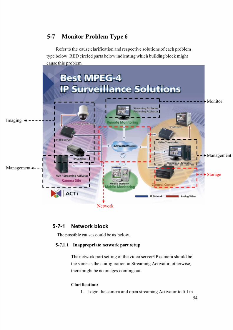
5-7 Monitor Problem Type 6
Refer to the cause clarification and respective solutions of each problem
type below. RED circled parts below indicating which building block mightcause this problem.
5-7-1 Network block
The possible causes could be as below.
5-7.1.1 Inappropriate network port setup
The network port setting of the video server/IP camera should be
the same as the configuration in Streaming Activator, otherwise,
there might be no images coming out.
Clarification:
1. Login the camera and open streaming Activator to fill in
Network
Management
Storage
maging
Monitor
Management
8/21/2019 IP Surveillance TroubleShooting Guide_V0.9
http://slidepdf.com/reader/full/ip-surveillance-troubleshooting-guidev09 57/347
55
the port setting table below.
FunctionPort
Function
Video
Server/IP
camera
Streaming
Activator Default value
HTTP 80
Register 6000
Monitor
Streaming 6002
2. Check each function port and see if it is the same in both
video server/IP camera and the Streaming Activator
(below is a reference result)
FunctionPort
Function
Video
Server/IP
camera
Streaming
Activator The same?
HTTP 80 80 Yes
Register 6000 7000 NO
Monitor
Streaming 6002 7002 NO
3. If any of those are not the same, this is a port setting
problem.
4. If all these port setting are the same, this is not a port
setting problem.
Solution:
1. Adjust the setting of the streaming activator or video
server/IP camera to make the port setting is the same for
each port.
Example:
FunctionPort
Function
Video
Server/IP
camera
Streaming
Activator The same?
HTTP 80 80 Yes
Register 6000 7000
->6000
Yes
Monitor
Streaming 6002 7002 Yes
8/21/2019 IP Surveillance TroubleShooting Guide_V0.9
http://slidepdf.com/reader/full/ip-surveillance-troubleshooting-guidev09 58/347
56
->6002
5-7-2 If problem not solved, how to report this
problem?If the solution above can’t solve the problem, please gather the following
information and contact our sales. (Please see introduction about how to
contact).
5-7.2.1 Problem feedback table
Problem feedback table of login problem 1
Category Sub-category Description
Hard model Model number
Firmware Firmware version
Software model Use it to connect?
Software
version
Use it to connect?
IP address
Submask
Video Server
LAN IP setting
Gateway
Use it to connect?
IP address
Submask
Video Server
WAN IP setting
Gateway
Use it to connect?
IP address
Submask
PC IP setting
Gateway

8/21/2019 IP Surveillance TroubleShooting Guide_V0.9
http://slidepdf.com/reader/full/ip-surveillance-troubleshooting-guidev09 59/347
57
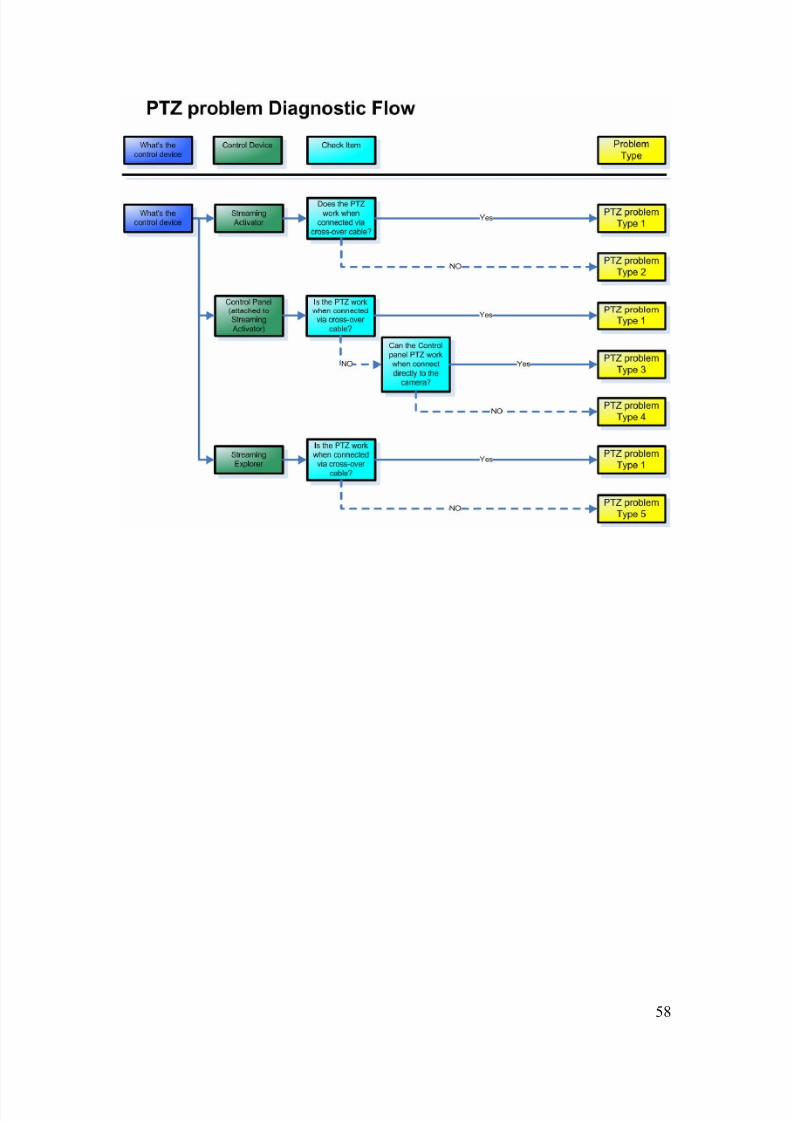
Chapter. 6. PTZ ProblemIn this Chapter, we will focus the problem that you can
1. Can login the video server/IP camera
2. Can monitor the image3. Can’t control camera’s PTZ function.
We will provide a diagnostic flow for customer to find out his problem type
within this problem category. Then we will examine the possible cause for each
problem type and find out the root cause and respective solutions.
6-1 Find out the possible cause
Please refer to the diagnostic flow to find out the problem type of the Login
Problem.Then you can refer to next section for advanced clarification and
troubleshooting.
Check Item Remark
Step1 Check the Control Device
Step2 Check if you can control the PTZ the
Video server/Transcoder’s analog outputon a TV monitor.
Step3 Connect the PC directly to the Video
server/Transcoder then via cross-over
cable. Then input the Video
server/Transcoder IP.
Step4 Refer to the section of each problem type
to do root cause clarification and find
respective solutions.
8/21/2019 IP Surveillance TroubleShooting Guide_V0.9
http://slidepdf.com/reader/full/ip-surveillance-troubleshooting-guidev09 60/347
58

8/21/2019 IP Surveillance TroubleShooting Guide_V0.9
http://slidepdf.com/reader/full/ip-surveillance-troubleshooting-guidev09 61/347
59
6-2 PTZ problem Type 1
Refer to the cause clarification and respective solutions of each problem
type below. RED circled parts below indicating which building block mightcause this problem.
6-2-1 Network block
The possible causes could be as below.
6-2.1.1 Inappropriate network infrastructure (if you were connecting
via LAN)
The problem could be the inappropriate network infrastructure.
Clarification:
1. Below is the status of this problem definition so far.
Network
Management
Storage
maging
Monitor
Management

8/21/2019 IP Surveillance TroubleShooting Guide_V0.9
http://slidepdf.com/reader/full/ip-surveillance-troubleshooting-guidev09 62/347
60
Network
environment Respective network ports
Function
Cross-over LAN Port name Port number (Default)
Login Yes Yes HTTP 80
HTTP 80
Register 6000
View image Yes Yes
Streaming 6002
PTZ control Yes No Control 6001
2. As you can see from the table, there’s something wrong
about your LAN.
Solution:
1. Because this problem involves mostly about your LAN
environment, it’s less possible for us to provide the
solution.
2. Please fill in your definition table
Network environment Respective network ports
Function
Cross-over LAN Port name Port number
Login Yes Yes HTTP
HTTP
Register
View image Yes Yes
Streaming
PTZ control Yes No Control
3. Please provide the definition table above to your MIS or
your network architect for this problem. Ask him for
solution.

8/21/2019 IP Surveillance TroubleShooting Guide_V0.9
http://slidepdf.com/reader/full/ip-surveillance-troubleshooting-guidev09 63/347
61
6-2.1.2 Inappropriate network port forwarding (if you wereconnecting via WAN)
The problem could be the inappropriate network transmission.
Network transmission involves correct setting below. Then we put
them all together.
Network transmission check table
Category Sub-category
Internet connectivityVideo Server
Port setting
Port forwarding Network
Firewall setting
PC Internet connectivity
Clarification:
1. Below is the status of this problem definition so far.
Network environment
Respective network ports
Function
Cross-over WAN Port name Port number
(Default)
Login Yes Yes HTTP 80
HTTP 80
Register 6000
Monitor Yes Yes
Streaming 6002
PTZ Yes No Control 6001
2. As you can see from the table, there’s something wrongabout your WAN.
3. Please read the support package TS-00009 attached.
- Chapter 1~3: How does internet communication works
- Appendix C : How to check the network
communication for Monitoring images
4. If the check fails, this is a network communication
problem.

8/21/2019 IP Surveillance TroubleShooting Guide_V0.9
http://slidepdf.com/reader/full/ip-surveillance-troubleshooting-guidev09 64/347
62
5. If the check ok, this is not a network communication
problem.
Solution:
1. Follows the support package TS-00009 to build up the
internet communication step by step. .
6-2.1.3 Blocked by firewall (if you were connecting via WAN)
The problem is discussed in 6-5.1.2, please go there for details.
6-2.1.4 DNS problem (if you were connecting via DNS)
This problem could happen if you connect to the video server/IP
camera using Domain Name (Ex: http://myroom.dyndns.org)
instead of IP address (Ex: http://59.233.23.59).
Clarification:
1. Please switch the software setting from IP address from
Domain Name to IP address and see if you can monitor
the images.
2. If yes, this is a DNS problem.
3. If not, this is not a DNS problem.
Solution:
1. Report the following information to our sales. We will
provide you an updated version A.S.A.P.
Category Description Example:
HardwareModel number
SED-2120
Firmware
version
A1D-V2.00.00
Software model NVR
Software
version
V1.00.00
2. Before you get that updated version, you can use IP
8/21/2019 IP Surveillance TroubleShooting Guide_V0.9
http://slidepdf.com/reader/full/ip-surveillance-troubleshooting-guidev09 65/347
63
address instead of Domain name to connect to the video
server/IP camera and a contingency plan.
6-2-2 If problem not solved, how to report this
problem?
If the solution above can’t solve the problem, please gather the following
information and contact our sales. (Please see introduction about how to
contact).
6-2.2.1 Problem feedback table
Problem feedback table of login problem 1
Category Sub-category Description
Product model Model number
Firmware Firmware version
Use it to connect?
IP address
Submask
Video Server
LAN IP setting
Gateway
Use it to connect?
IP address
Submask
Video Server
WAN IP setting
Gateway
Use it to connect?
IP address
Submask
PC IP setting
Gateway
Network diagram Network
deployment Respective setting of
switch / routers.

8/21/2019 IP Surveillance TroubleShooting Guide_V0.9
http://slidepdf.com/reader/full/ip-surveillance-troubleshooting-guidev09 66/347
64
6-3 PTZ problem Type 2
Refer to the cause clarification and respective solutions of each problem
type below. RED circled parts below indicating which building block mightcause this problem.
6-3-1 Image block
The possible causes could be as below.
6-3.1.1 Inappropriate Analog video –Serial setting (Baud rate, Parity,
Bit length, Stop bit)
These serial setting (baud rate, parity, stop bit) must be the same
for analog video and network platform for PTZ function to work.
We will include both sections in this chapter below.
Network
Management
Storage
maging
Monitor
Management
8/21/2019 IP Surveillance TroubleShooting Guide_V0.9
http://slidepdf.com/reader/full/ip-surveillance-troubleshooting-guidev09 67/347
65
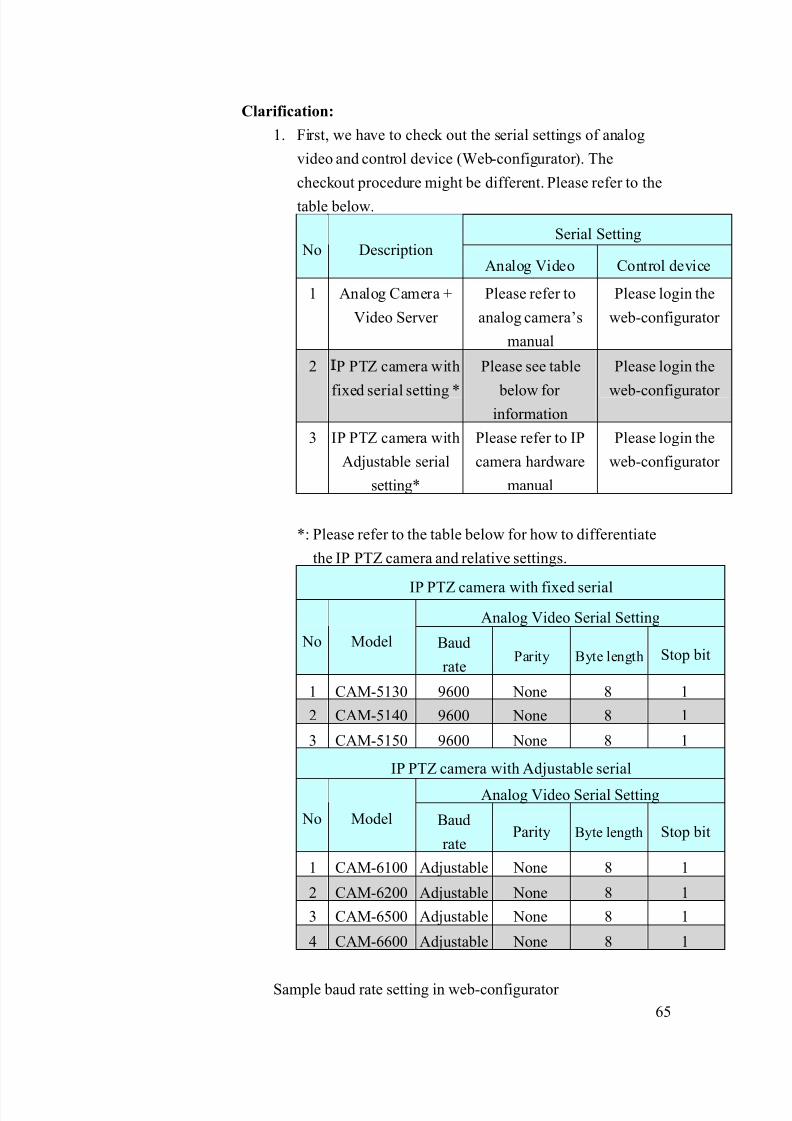
Clarification:
1. First, we have to check out the serial settings of analog
video and control device (Web-configurator). The
checkout procedure might be different. Please refer to the
table below.
Serial Setting No Description
Analog Video Control device
1 Analog Camera +
Video Server
Please refer to
analog camera’s
manual
Please login the
web-configurator
2 P PTZ camera with
fixed serial setting *
Please see table
below for information
Please login the
web-configurator
3 IP PTZ camera with
Adjustable serial
setting*
Please refer to IP
camera hardware
manual
Please login the
web-configurator
*: Please refer to the table below for how to differentiate
the IP PTZ camera and relative settings.
IP PTZ camera with fixed serial
Analog Video Serial Setting
No Model Baud
rate Parity Byte length Stop bit
1 CAM-5130 9600 None 8 1
2 CAM-5140 9600 None 8 1
3 CAM-5150 9600 None 8 1
IP PTZ camera with Adjustable serial
Analog Video Serial Setting
No Model Baud
rateParity Byte length Stop bit
1 CAM-6100 Adjustable None 8 1
2 CAM-6200 Adjustable None 8 1
3 CAM-6500 Adjustable None 8 1
4 CAM-6600 Adjustable None 8 1
Sample baud rate setting in web-configurator
8/21/2019 IP Surveillance TroubleShooting Guide_V0.9
http://slidepdf.com/reader/full/ip-surveillance-troubleshooting-guidev09 68/347
66
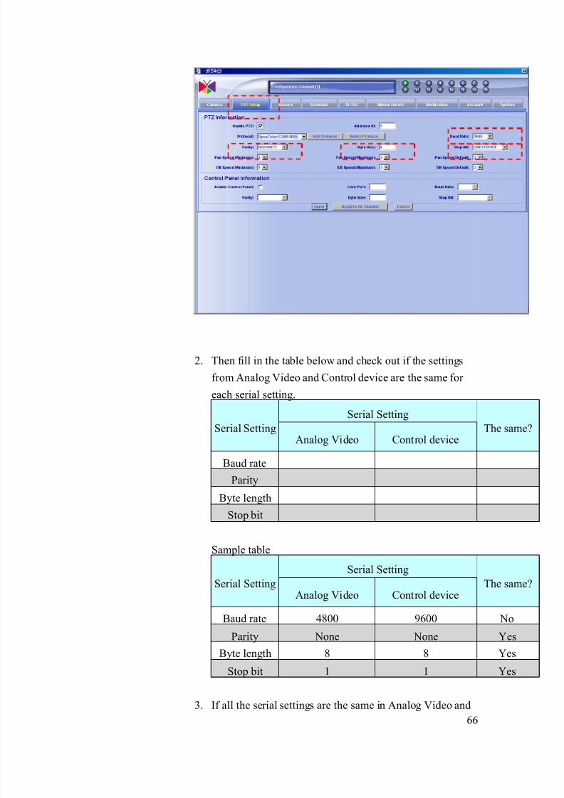
2. Then fill in the table below and check out if the settings
from Analog Video and Control device are the same for
each serial setting.
Serial SettingSerial SettingAnalog Video Control device
The same?
Baud rate
Parity
Byte length
Stop bit
Sample table
Serial Setting
Serial SettingAnalog Video Control device
The same?
Baud rate 4800 9600 No
Parity None None Yes
Byte length 8 8 Yes
Stop bit 1 1 Yes
3. If all the serial settings are the same in Analog Video and

8/21/2019 IP Surveillance TroubleShooting Guide_V0.9
http://slidepdf.com/reader/full/ip-surveillance-troubleshooting-guidev09 69/347
67
Network platform, this is not a Serial Setting issue.
4. If any of the serial settings is not the in Analog Video and
Network platform, this is a Serial Setting issue.
Solution:
1. Follow the table below to adjust the setting of the Analog
Video and Control device and make all the serial settings
the same. (for how to adjust each setting, please refer to
hardware manual and software manual)
Example:
.Before
Serial Setting
Serial SettingAnalog Video Control device
The same?
Baud rate 4800 9600 No
Parity None None Yes
Byte length 8 8 Yes
Stop bit 1 1 Yes
.After
Serial Setting
Serial SettingAnalog Video Network Platform
The same?
Baud rate 4800 4800 yes
Parity None None Yes
Byte length 8 8 YesStop bit 1 1 Yes
6-3.1.2 Inappropriate Network platform - Serial Setting (Baud rate,
Parity, Bit length, Stop bit)
The problem is discussed in 6-3.1.1, please go there for details.

8/21/2019 IP Surveillance TroubleShooting Guide_V0.9
http://slidepdf.com/reader/full/ip-surveillance-troubleshooting-guidev09 70/347
68
6-3.1.3 Inappropriate Analog video - Protocol setting
These PTZ settings (Protocol and Camera ID) must be the same for
Analog Video and Controlled device for PTZ function to work. We
will include both sections in this chapter below.Clarification:
1. First, we have to check out the protocol of analog video
and the controlled device (depends on what device you use
to control the PTZ) the checkout procedure might be
different. Please refer to the table below.
PTZ setting No Description
Analog Video Control device
1 Analog Camera +
Video Server
Please refer to
analog camera’s
manual
Please go the
control device PTZ
setup page
2 P PTZ camera with
fixed serial setting *
Please see table
below for
information
Please go the
control device PTZ
setup page
3 IP PTZ camera with
Adjustable serial
setting*
Please refer to IP
camera hardware
manual
Please go the
control device PTZ
setup page
*: Please refer to the table below for how to differentiate the
IP PTZ camera and relative settings.
IP PTZ camera with fixed PTZ setting
No Model Protocol setting Camera ID
1 CAM-5130 Campro_V1 1
2 CAM-5140 Campro_V1 1
3 CAM-5150 Campro_V1 1
IP PTZ camera with Adjustable PTZ setting
No Model Protocol setting Camera ID
1 CAM-6100 Adjustable Camera ID (Pelco-P,
Pelco-D, VCL)
Adjustable
(1~255)
2 CAM-6200 Adjustable Camera ID (Pelco-P,
Pelco-D, Eyeview)
Adjustable
(1~255)
3 CAM-6500 Adjustable Camera ID (Pelco-P, Adjustable
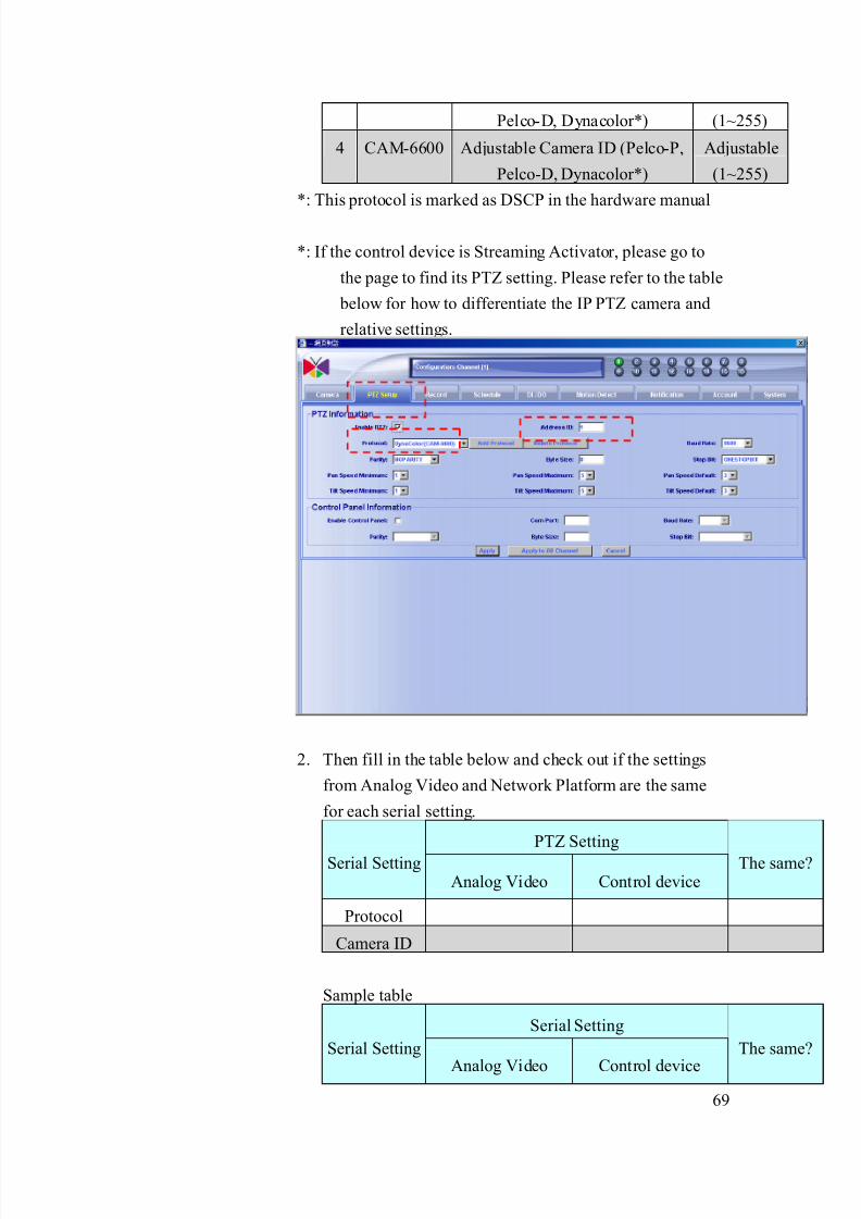
8/21/2019 IP Surveillance TroubleShooting Guide_V0.9
http://slidepdf.com/reader/full/ip-surveillance-troubleshooting-guidev09 71/347
69
Pelco-D, Dynacolor*) (1~255)
4 CAM-6600 Adjustable Camera ID (Pelco-P,
Pelco-D, Dynacolor*)
Adjustable
(1~255)
*: This protocol is marked as DSCP in the hardware manual
*: If the control device is Streaming Activator, please go to
the page to find its PTZ setting. Please refer to the table
below for how to differentiate the IP PTZ camera and
relative settings.
2. Then fill in the table below and check out if the settings
from Analog Video and Network Platform are the same
for each serial setting.
PTZ Setting
Serial SettingAnalog Video Control device
The same?
Protocol
Camera ID
Sample table
Serial Setting
Serial Setting
Analog Video Control device
The same?
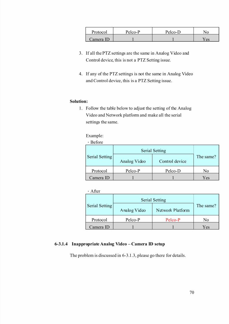
8/21/2019 IP Surveillance TroubleShooting Guide_V0.9
http://slidepdf.com/reader/full/ip-surveillance-troubleshooting-guidev09 72/347
70
Protocol Pelco-P Pelco-D No
Camera ID 1 1 Yes
3. If all the PTZ settings are the same in Analog Video and
Control device, this is not a PTZ Setting issue.
4. If any of the PTZ settings is not the same in Analog Video
and Control device, this is a PTZ Setting issue.
Solution:
1. Follow the table below to adjust the setting of the Analog
Video and Network platform and make all the serial
settings the same.
Example:
.Before
Serial Setting
Serial SettingAnalog Video Control device
The same?
Protocol Pelco-P Pelco-D No
Camera ID 1 1 Yes
.After
Serial Setting
Serial SettingAnalog Video Network Platform
The same?
Protocol Pelco-P Pelco-P No
Camera ID 1 1 Yes
6-3.1.4 Inappropriate Analog Video – Camera ID setup
The problem is discussed in 6-3.1.3, please go there for details.

8/21/2019 IP Surveillance TroubleShooting Guide_V0.9
http://slidepdf.com/reader/full/ip-surveillance-troubleshooting-guidev09 73/347
71
6-3.1.5 Inappropriate Network platform - Serial type setup (if you areconnecting a video server to an analog camera)
The serial connection problem (might happen ONLY on video
server + analog cameras. If you are not using video servers +
analog cameras, please skip this section.
The serial connection type and serial physical connection have to
be right on both “Video server” and “Analog cameras” for PTZ
function to work. Thus we put them both.
Clarification:
1. Check out the serial connection type of the analog camera
and video servers and fill in the table below.
Serial Connection type No Description
Analog camera Video server
1 RS-485 * Default
2 RS-232 *
3 RS-422 *
*: Please refer to the analog camera’s hardware manual for
its serial connection type.
Sample table
Serial Connection type No Description
Analog camera Video server
1 RS-485 Default
2 RS-232
3 RS-422 Yes
2. If all the Serial Connection type is the same in Analog
Camera and Video server, this is not a Serial Connection
type. Then we go on next step to check out serial physical
connection.
3. If any of the Serial Connection type is not the same in
Analog Camera and Video server, this is a Serial
Connection type issue. Please go to solution to solve it
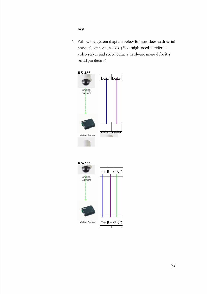
8/21/2019 IP Surveillance TroubleShooting Guide_V0.9
http://slidepdf.com/reader/full/ip-surveillance-troubleshooting-guidev09 74/347
72
first.
4. Follow the system diagram below for how does each serial
physical connection goes. (You might need to refer to
video server and speed dome’s hardware manual for it’s
serial pin details)
RS-485:
RS-232:
Data+ Data-
Data+ Data-
T+ R+ GND
T+ R+ GND
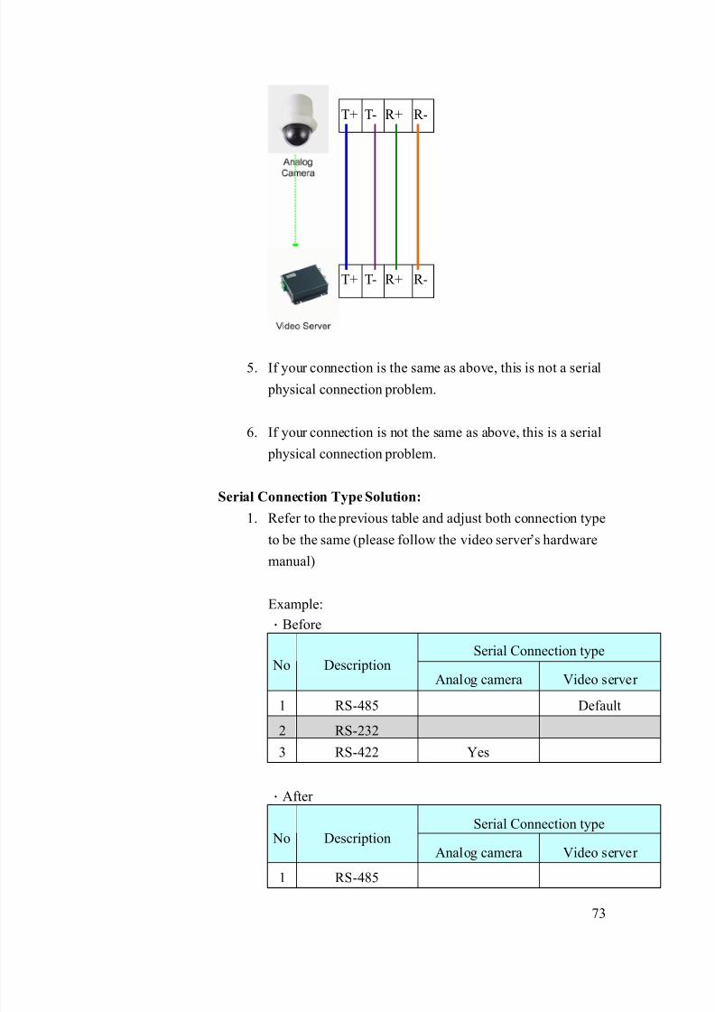
8/21/2019 IP Surveillance TroubleShooting Guide_V0.9
http://slidepdf.com/reader/full/ip-surveillance-troubleshooting-guidev09 75/347
73
5. If your connection is the same as above, this is not a serial
physical connection problem.
6. If your connection is not the same as above, this is a serial
physical connection problem.
Serial Connection Type Solution:
1. Refer to the previous table and adjust both connection type
to be the same (please follow the video server’s hardware
manual)
Example:
.Before
Serial Connection type No Description
Analog camera Video server
1 RS-485 Default2 RS-232
3 RS-422 Yes
.After
Serial Connection type No Description
Analog camera Video server
1 RS-485
T+ T- R+ R-
T+ T- R+ R-

8/21/2019 IP Surveillance TroubleShooting Guide_V0.9
http://slidepdf.com/reader/full/ip-surveillance-troubleshooting-guidev09 76/347
74
2 RS-232
3 RS-422 Yes Yes
Serial Physical Connection Solution:
1. Follow the serial physical connection diagram in
Clarification Step 4. Then correct them accordingly.
6-3.1.6 Inappropriate Network platform - Serial Physical Connection
(if you are connecting a video server to an analog camera)
The problem is discussed in 6-3.1.5, please go there for details.
.
6-3-2 Network block
The possible causes could be as below.
6-3.2.1 Inappropriate network port setup
The network port setting of the video server/IP camera should be
the same as the configuration in Streaming Activator, otherwise,
there might be no images coming out.
Clarification:
1. Login the camera and open streaming Activator to fill in
the port setting table below.
FunctionPort
Function
Video
Server/IP
camera
Streaming
Activator Default value
HTTP 80
Register 6000
Streaming 6002
Monitor
Control 6001
2. Check each function port and see if it is the same in both
video server/IP camera and the Streaming Activator
(below is a reference result)
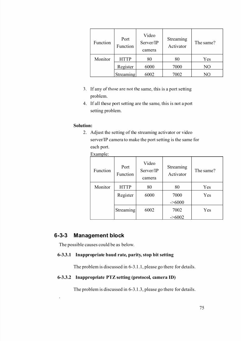
8/21/2019 IP Surveillance TroubleShooting Guide_V0.9
http://slidepdf.com/reader/full/ip-surveillance-troubleshooting-guidev09 77/347
75
FunctionPort
Function
Video
Server/IP
camera
Streaming
Activator The same?
HTTP 80 80 YesRegister 6000 7000 NO
Monitor
Streaming 6002 7002 NO
3. If any of those are not the same, this is a port setting
problem.
4. If all these port setting are the same, this is not a port
setting problem.
Solution:
2. Adjust the setting of the streaming activator or video
server/IP camera to make the port setting is the same for
each port.
Example:
FunctionPort
Function
Video
Server/IP
camera
Streaming
Activator The same?
HTTP 80 80 Yes
Register 6000 7000
->6000
Yes
Monitor
Streaming 6002 7002
->6002
Yes
6-3-3 Management block
The possible causes could be as below.
6-3.3.1 Inappropriate baud rate, parity, stop bit setting
The problem is discussed in 6-3.1.1, please go there for details.
6-3.3.2 Inappropriate PTZ setting (protocol, camera ID)
The problem is discussed in 6-3.1.3, please go there for details.
.

8/21/2019 IP Surveillance TroubleShooting Guide_V0.9
http://slidepdf.com/reader/full/ip-surveillance-troubleshooting-guidev09 78/347
76
6-3-4 If problem not solved, how to report this
problem?
If the solution above can’t solve the problem, please gather the following
information and contact our sales. (Please see introduction about how to
contact).
6-3.4.1 Problem feedback table
Problem feedback table of login problem 1
Category Sub-category Description
Hard model Model number
Firmware Firmware version
Software model
Software
version
Serial Type
Connection diagram
Baud rate
Analog Video
Serial setting
Byte length, stop bit
HTTP port
Streaming port
Control port
Network
Platform
Register port
Serial Type
Connection diagram
Baud rate
Software PTZ
setting
Byte length, stop bit
HTTP port
Streaming port
Control port
Software port
setting
Register port
Other details
you find during
clarification

8/21/2019 IP Surveillance TroubleShooting Guide_V0.9
http://slidepdf.com/reader/full/ip-surveillance-troubleshooting-guidev09 79/347
77
6-4 PTZ problem Type 3
Refer to the cause clarification and respective solutions of each problem
type below. RED circled parts below indicating which building block mightcause this problem.
6-4-1 Management block
The possible causes could be as below.
6-4.1.1 Inappropriate control panel connection
The Control panel connection to Streaming Activator PC might be
wrong and cause the PTZ control to fail.
Network
Management
Storage
maging
Monitor
Management

8/21/2019 IP Surveillance TroubleShooting Guide_V0.9
http://slidepdf.com/reader/full/ip-surveillance-troubleshooting-guidev09 80/347
78
Clarification:
1. Check out the control panel connection type by referring
to the hardware manual
No Description Serial Connection type
1 RS-485
2 RS-232
3 RS-422
2. Check if the connection between the control panel and the
streaming activator PC as below. (please follow the
converter manual for how to connect)
No Description Connection
1 RS-485 Control panel
=>Serial converter (RS-485 to RS-232)
=> PC com port
2 RS-232 Control panel
=> PC com port
3 RS-422 Control panel
=>Serial converter (RS-422 to RS-232)
=> PC com port
3. If the connection is right, this is not control panel
connection problem.
4. If the connection is not right, this is a control panel
connection problem.
Solution:1. Please follow the system diagram above in the problem
clarification and modify the connections.
6-4.1.2 Inappropriate Panel connection setting setting (Baud rate,
Parity, Byte length, Stop bit, Com port setting)
These Panel connection settings have to be the same for the control
panel and the streaming activator for this function to work. P
8/21/2019 IP Surveillance TroubleShooting Guide_V0.9
http://slidepdf.com/reader/full/ip-surveillance-troubleshooting-guidev09 81/347
79
Clarification:
1. First, we have to check out these Panel connection settings
of control panel and streaming activator. And fill in the
table below.
Panel connection settings No Description
Control Panel Streaming Activator
1 Baud rate * **
2 Parity * **
3 Byte length * **
4 Stop bit * **
5 Com port * **
*: Please refer to the hardware manual for details
**: Please login the activator to view the settings as below
2. Check if all the setting is the same.
Sample table:
Panel connection settings No Description
Control Panel Streaming Activator
The
same?
1 Baud rate 4800 9600 No
2 Parity No No Yes
3 Byte length 8 8 Yes
4 Stop bit 1 1 Yes
5 Com port 2 2 Yes

8/21/2019 IP Surveillance TroubleShooting Guide_V0.9
http://slidepdf.com/reader/full/ip-surveillance-troubleshooting-guidev09 82/347
80
3. If all the settings are the same, this is not a Panel
connection settings problem.
4. If any of the settings is not the same, this is a Panel
connection setting problem.
Solution:
1. Follow the table below to adjust the setting of the Control
Panel and Streaming Activator and make all the Panel
connection settings. (for how to adjust each setting, please
refer to hardware manual and software manual)

8/21/2019 IP Surveillance TroubleShooting Guide_V0.9
http://slidepdf.com/reader/full/ip-surveillance-troubleshooting-guidev09 83/347
81
6-5 PTZ problem Type 4
Refer to the cause clarification and respective solutions of each problem
type below. RED circled parts below indicating which building block mightcause this problem.
6-5-1 Image block
The possible causes could be as below.
6-5.1.1 Inappropriate Analog video –Serial setting (Baud rate, Parity,
Bit length, Stop bit)
These serial setting (baud rate, parity, stop bit) must be the same
for analog video and network platform for PTZ function to work.
We will include both sections in this chapter below.
Network
Management
Storage
maging
Monitor
Management

8/21/2019 IP Surveillance TroubleShooting Guide_V0.9
http://slidepdf.com/reader/full/ip-surveillance-troubleshooting-guidev09 84/347
82
Clarification:
1. First, we have to check out the serial settings of analog
video and control device (Control Panel). The checkout
procedure might be different. Please refer to the table
below.
Serial Setting No Description
Analog Video Control Panel
1 Analog Camera +
Video Server
Please refer to
analog camera’s
manual
Please refer to the
control panel
hardware manual
2 IP PTZ camera with
fixed serial setting *
Please see table
below for information
Please refer to the
control panelhardware manual
3 IP PTZ camera with
Adjustable serial
setting*
Please refer to IP
camera hardware
manual
Please refer to the
control panel
hardware manual
*: Please refer to the table below for how to differentiate
the IP PTZ camera and relative settings.
IP PTZ camera with fixed serial
Analog Video Serial Setting
No Model Baud
rate Parity Byte length Stop bit
1 CAM-5130 9600 None 8 1
2 CAM-5140 9600 None 8 1
3 CAM-5150 9600 None 8 1
IP PTZ camera with Adjustable serial
Analog Video Serial Setting
No Model Baud
rateParity Byte length Stop bit
1 CAM-6100 Adjustable None 8 1
2 CAM-6200 Adjustable None 8 1
3 CAM-6500 Adjustable None 8 1
4 CAM-6600 Adjustable None 8 1
2. Then fill in the table below and check out if the settings
from Analog Video and Control Panel are the same for
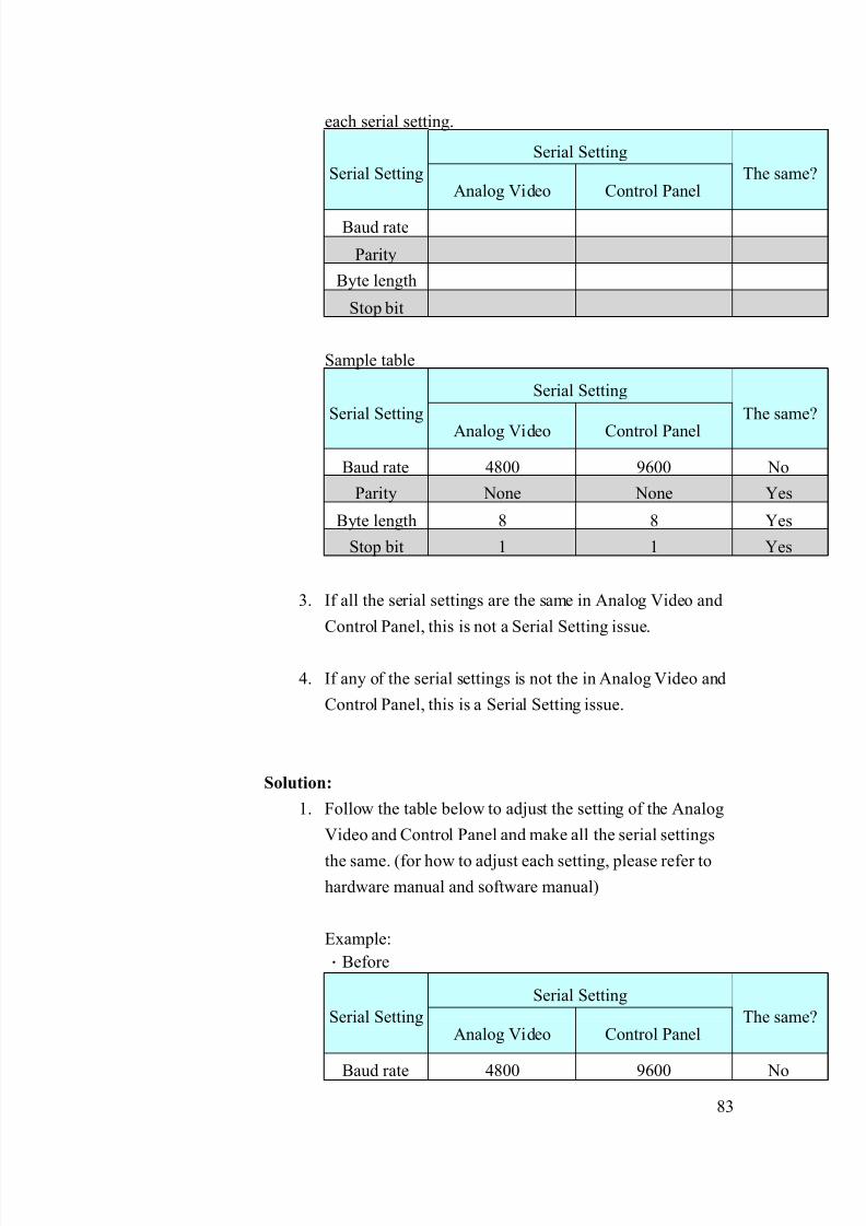
8/21/2019 IP Surveillance TroubleShooting Guide_V0.9
http://slidepdf.com/reader/full/ip-surveillance-troubleshooting-guidev09 85/347
83
each serial setting.
Serial Setting
Serial SettingAnalog Video Control Panel
The same?
Baud rate
Parity
Byte length
Stop bit
Sample table
Serial Setting
Serial Setting
Analog Video Control Panel
The same?
Baud rate 4800 9600 No
Parity None None Yes
Byte length 8 8 Yes
Stop bit 1 1 Yes
3. If all the serial settings are the same in Analog Video and
Control Panel, this is not a Serial Setting issue.
4. If any of the serial settings is not the in Analog Video and
Control Panel, this is a Serial Setting issue.
Solution:
1. Follow the table below to adjust the setting of the Analog
Video and Control Panel and make all the serial settings
the same. (for how to adjust each setting, please refer to
hardware manual and software manual)
Example:
.Before
Serial Setting
Serial SettingAnalog Video Control Panel
The same?
Baud rate 4800 9600 No

8/21/2019 IP Surveillance TroubleShooting Guide_V0.9
http://slidepdf.com/reader/full/ip-surveillance-troubleshooting-guidev09 86/347
84
Parity None None Yes
Byte length 8 8 Yes
Stop bit 1 1 Yes
.After
Serial Setting
Serial SettingAnalog Video Control Panel
The same?
Baud rate 4800 4800 yes
Parity None None Yes
Byte length 8 8 Yes
Stop bit 1 1 Yes
6-5.1.2 Inappropriate Network platform - Serial Setting (Baud rate,
Parity, Bit length, Stop bit)
The problem is discussed in 6-3.1.1, please go there for details.
6-5.1.3 Inappropriate Analog video - Protocol setting
These PTZ settings (Protocol and Camera ID) must be the same for
Analog Video and Controlled device for PTZ function to work. We
will include both sections in this chapter below.
Clarification:
2. First, we have to check out the protocol of analog video
and the controlled device (depends on what device you use
to control the PTZ) the checkout procedure might be
different. Please refer to the table below.
PTZ setting No Description
Analog Video Control Panel
1 Analog Camera +
Video Server
Please refer to
analog camera’s
manual
Please go the
control device PTZ
setup page
2 IP PTZ camera with
fixed serial setting *
Please see table
below for
information
Please go the
control device PTZ
setup page
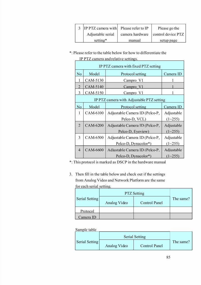
8/21/2019 IP Surveillance TroubleShooting Guide_V0.9
http://slidepdf.com/reader/full/ip-surveillance-troubleshooting-guidev09 87/347
85
3 IP PTZ camera with
Adjustable serial
setting*
Please refer to IP
camera hardware
manual
Please go the
control device PTZ
setup page
*: Please refer to the table below for how to differentiate the
IP PTZ camera and relative settings.
IP PTZ camera with fixed PTZ setting
No Model Protocol setting Camera ID
1 CAM-5130 Campro_V1 1
2 CAM-5140 Campro_V1 1
3 CAM-5150 Campro_V1 1
IP PTZ camera with Adjustable PTZ setting
No Model Protocol setting Camera ID
1 CAM-6100 Adjustable Camera ID (Pelco-P,
Pelco-D, VCL)
Adjustable
(1~255)
2 CAM-6200 Adjustable Camera ID (Pelco-P,
Pelco-D, Eyeview)
Adjustable
(1~255)
3 CAM-6500 Adjustable Camera ID (Pelco-P,
Pelco-D, Dynacolor*)
Adjustable
(1~255)
4 CAM-6600 Adjustable Camera ID (Pelco-P,
Pelco-D, Dynacolor*)
Adjustable
(1~255)
*: This protocol is marked as DSCP in the hardware manual
3. Then fill in the table below and check out if the settings
from Analog Video and Network Platform are the same
for each serial setting.
PTZ Setting
Serial Setting Analog Video Control Panel The same?
Protocol
Camera ID
Sample table
Serial Setting
Serial SettingAnalog Video Control Panel
The same?

8/21/2019 IP Surveillance TroubleShooting Guide_V0.9
http://slidepdf.com/reader/full/ip-surveillance-troubleshooting-guidev09 88/347
86
Protocol Pelco-P Pelco-D No
Camera ID 1 1 Yes
5. If all the PTZ settings are the same in Analog Video and
Control Panel, this is not a PTZ Setting issue.
6. If any of the PTZ settings is not the same in Analog Video
and Control Panel, this is a PTZ S etting issue.
Solution:
3. Follow the table below to adjust the setting of the Analog
Video and Control Panel and make all the serial settings
the same.
Example:
.Before
Serial Setting
Serial SettingAnalog Video Control Panel
The same?
Protocol Pelco-P Pelco-D No
Camera ID 1 1 Yes
.After
Serial Setting
Serial SettingAnalog Video Control Panel
The same?
Protocol Pelco-P Pelco-P No
Camera ID 1 1 Yes
6-5.1.4 Inappropriate Analog Video – Camera ID setup
The problem is discussed in 6-3.1.3, please go there for details.

8/21/2019 IP Surveillance TroubleShooting Guide_V0.9
http://slidepdf.com/reader/full/ip-surveillance-troubleshooting-guidev09 89/347
87
6-5.1.5 Inappropriate Network platform - Serial type setup (if you areconnecting a video server to an analog camera)
The serial connection problem (might happen ONLY on video
server + analog cameras. If you are not using video servers +
analog cameras, please skip this section.
The serial connection type and serial physical connection have to
be right on both “Video server” and “Analog cameras” for PTZ
function to work. Thus we put them both.
Clarification:
1. Check out the serial connection type of the analog camera
and video servers and fill in the table below.
Serial Connection type No Description
Analog camera Video server
1 RS-485 * Default
2 RS-232 *
3 RS-422 *
*: Please refer to the analog camera’s hardware manual for
its serial connection type.
Sample table
Serial Connection type No Description
Analog camera Video server
1 RS-485 Default
2 RS-232
3 RS-422 Yes
2. If all the Serial Connection type is the same in Analog
Camera and Video server, this is not a Serial Connection
type. Then we go on next step to check out serial physical
connection.
3. If any of the Serial Connection type is not the same in
Analog Camera and Video server, this is a Serial
Connection type issue. Please go to solution to solve it

8/21/2019 IP Surveillance TroubleShooting Guide_V0.9
http://slidepdf.com/reader/full/ip-surveillance-troubleshooting-guidev09 90/347
88
first.
4. Follow the system diagram below for how does each serial
physical connection goes. (You might need to refer to
video server and speed dome’s hardware manual for it’s
serial pin details)
RS-485:
RS-232:
Data+ Data-
Data+ Data-
T+ R+ GND
T+ R+ GND
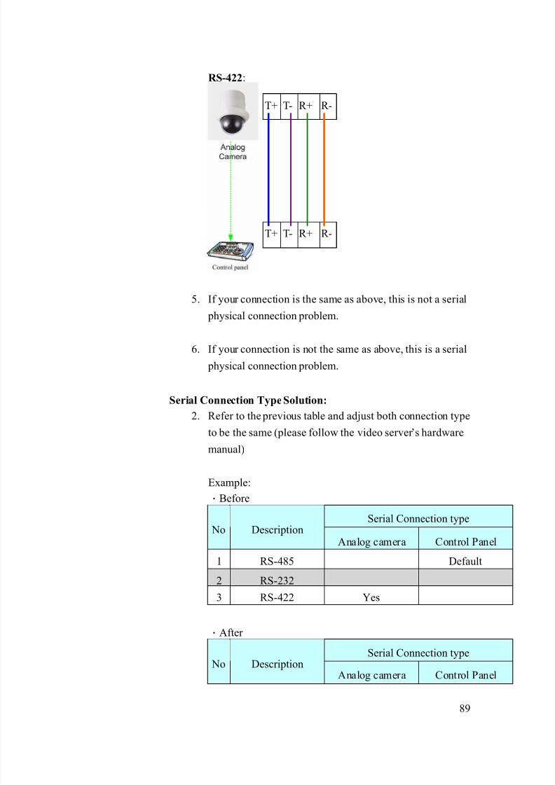
8/21/2019 IP Surveillance TroubleShooting Guide_V0.9
http://slidepdf.com/reader/full/ip-surveillance-troubleshooting-guidev09 91/347
89
RS-422:
5. If your connection is the same as above, this is not a serial
physical connection problem.
6. If your connection is not the same as above, this is a serial
physical connection problem.
Serial Connection Type Solution:
2. Refer to the previous table and adjust both connection type
to be the same (please follow the video server’s hardware
manual)
Example:
.Before
Serial Connection type No Description
Analog camera Control Panel
1 RS-485 Default
2 RS-232
3 RS-422 Yes
.After
Serial Connection type No Description
Analog camera Control Panel
T+ T- R+ R-
T+ T- R+ R-
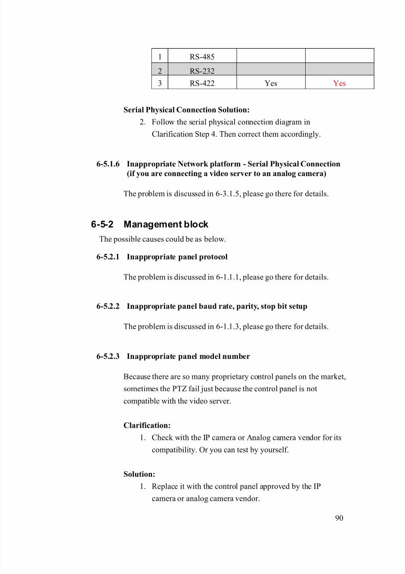
8/21/2019 IP Surveillance TroubleShooting Guide_V0.9
http://slidepdf.com/reader/full/ip-surveillance-troubleshooting-guidev09 92/347
90
1 RS-485
2 RS-232
3 RS-422 Yes Yes
Serial Physical Connection Solution:
2. Follow the serial physical connection diagram in
Clarification Step 4. Then correct them accordingly.
6-5.1.6 Inappropriate Network platform - Serial Physical Connection
(if you are connecting a video server to an analog camera)
The problem is discussed in 6-3.1.5, please go there for details.
6-5-2 Management block
The possible causes could be as below.
6-5.2.1 Inappropriate panel protocol
The problem is discussed in 6-1.1.1, please go there for details.
6-5.2.2 Inappropriate panel baud rate, parity, stop bit setup
The problem is discussed in 6-1.1.3, please go there for details.
6-5.2.3 Inappropriate panel model number
Because there are so many proprietary control panels on the market,
sometimes the PTZ fail just because the control panel is not
compatible with the video server.
Clarification:
1. Check with the IP camera or Analog camera vendor for its
compatibility. Or you can test by yourself.
Solution:
1. Replace it with the control panel approved by the IP
camera or analog camera vendor.

8/21/2019 IP Surveillance TroubleShooting Guide_V0.9
http://slidepdf.com/reader/full/ip-surveillance-troubleshooting-guidev09 93/347
91
6-6 PTZ problem Type 5
Refer to the cause clarification and respective solutions of each problem
type below. RED circled parts below indicating which building block mightcause this problem.
6-6-1 Image block
Refer to the cause clarification and respective solutions of each problem
type below. RED circled parts below indicating which building block might
cause this problem.
Network
Management
Storage
maging
Monitor
Management
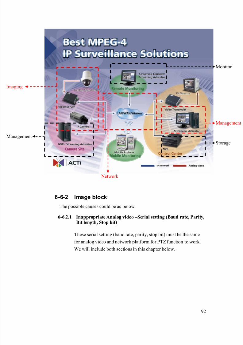
8/21/2019 IP Surveillance TroubleShooting Guide_V0.9
http://slidepdf.com/reader/full/ip-surveillance-troubleshooting-guidev09 94/347
92
6-6-2 Image block
The possible causes could be as below.
6-6.2.1 Inappropriate Analog video –Serial setting (Baud rate, Parity,Bit length, Stop bit)
These serial setting (baud rate, parity, stop bit) must be the same
for analog video and network platform for PTZ function to work.We will include both sections in this chapter below.
Network
Management
Storage
maging
Monitor
Management
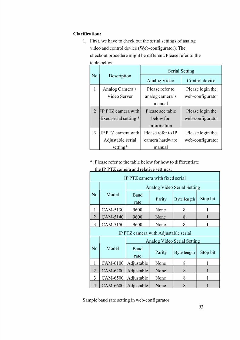
8/21/2019 IP Surveillance TroubleShooting Guide_V0.9
http://slidepdf.com/reader/full/ip-surveillance-troubleshooting-guidev09 95/347
93
Clarification:
1. First, we have to check out the serial settings of analog
video and control device (Web-configurator). The
checkout procedure might be different. Please refer to the
table below.
Serial Setting No Description
Analog Video Control device
1 Analog Camera +
Video Server
Please refer to
analog camera’s
manual
Please login the
web-configurator
2 P PTZ camera with
fixed serial setting *
Please see table
below for information
Please login the
web-configurator
3 IP PTZ camera with
Adjustable serial
setting*
Please refer to IP
camera hardware
manual
Please login the
web-configurator
*: Please refer to the table below for how to differentiate
the IP PTZ camera and relative settings.
IP PTZ camera with fixed serial
Analog Video Serial Setting
No Model Baud
rate Parity Byte length Stop bit
1 CAM-5130 9600 None 8 1
2 CAM-5140 9600 None 8 1
3 CAM-5150 9600 None 8 1
IP PTZ camera with Adjustable serial
Analog Video Serial Setting
No Model Baud
rateParity Byte length Stop bit
1 CAM-6100 Adjustable None 8 1
2 CAM-6200 Adjustable None 8 1
3 CAM-6500 Adjustable None 8 1
4 CAM-6600 Adjustable None 8 1
Sample baud rate setting in web-configurator

8/21/2019 IP Surveillance TroubleShooting Guide_V0.9
http://slidepdf.com/reader/full/ip-surveillance-troubleshooting-guidev09 96/347
94
2. Then fill in the table below and check out if the settings
from Analog Video and Control device are the same for
each serial setting.
Serial Setting
Serial SettingAnalog Video Control device
The same?
Baud rate
Parity
Byte length
Stop bit
Sample table
Serial Setting
Serial SettingAnalog Video Control device
The same?
Baud rate 4800 9600 No
Parity None None Yes
Byte length 8 8 Yes
Stop bit 1 1 Yes
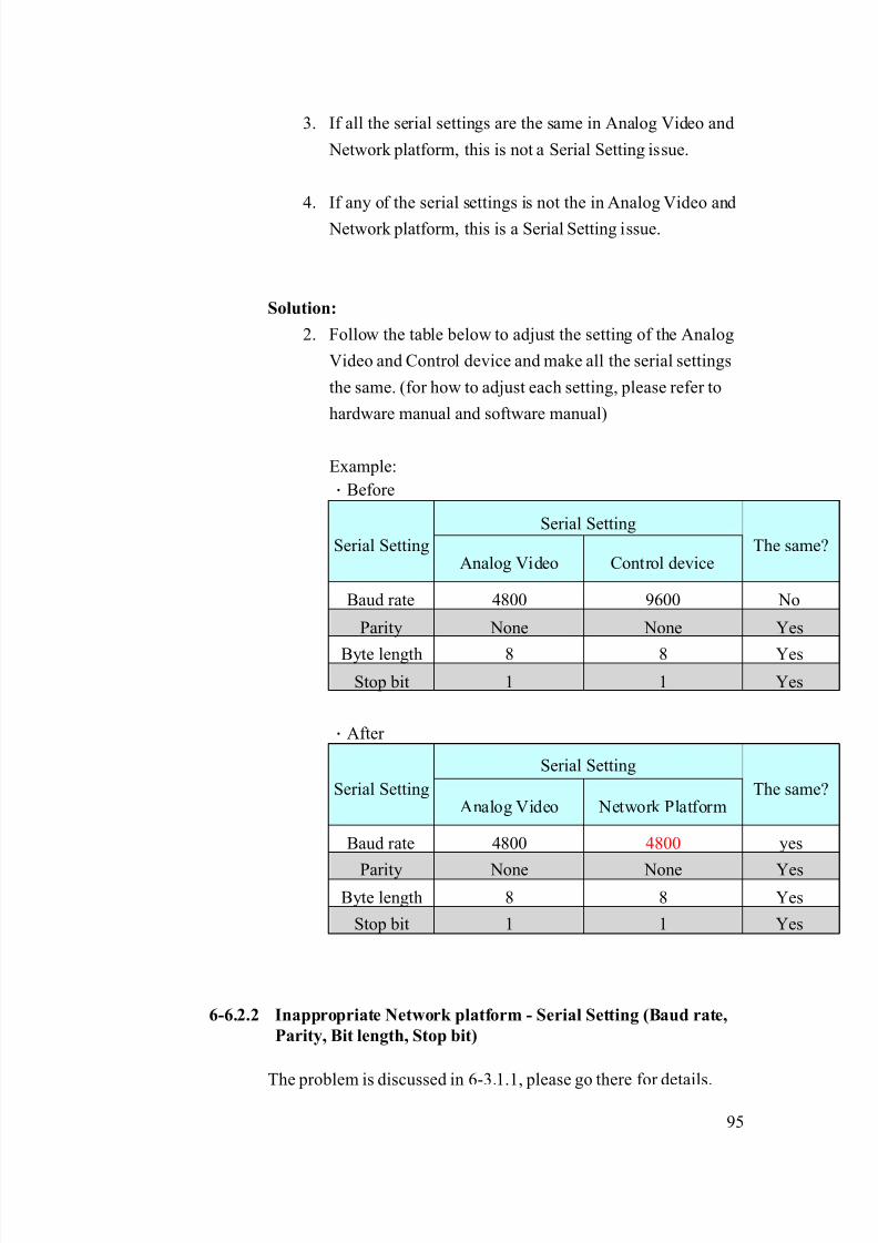
8/21/2019 IP Surveillance TroubleShooting Guide_V0.9
http://slidepdf.com/reader/full/ip-surveillance-troubleshooting-guidev09 97/347
95
3. If all the serial settings are the same in Analog Video and
Network platform, this is not a Serial Setting issue.
4. If any of the serial settings is not the in Analog Video and
Network platform, this is a Serial Setting issue.
Solution:
2. Follow the table below to adjust the setting of the Analog
Video and Control device and make all the serial settings
the same. (for how to adjust each setting, please refer to
hardware manual and software manual)
Example:
.Before
Serial Setting
Serial SettingAnalog Video Control device
The same?
Baud rate 4800 9600 No
Parity None None Yes
Byte length 8 8 Yes
Stop bit 1 1 Yes
.After
Serial Setting
Serial SettingAnalog Video Network Platform
The same?
Baud rate 4800 4800 yes
Parity None None YesByte length 8 8 Yes
Stop bit 1 1 Yes
6-6.2.2 Inappropriate Network platform - Serial Setting (Baud rate,
Parity, Bit length, Stop bit)
The problem is discussed in 6-3.1.1, please go there for details.

8/21/2019 IP Surveillance TroubleShooting Guide_V0.9
http://slidepdf.com/reader/full/ip-surveillance-troubleshooting-guidev09 98/347
96
6-6.2.3 Inappropriate Analog video - Protocol setting
These PTZ settings (Protocol and Camera ID) must be the same for
Analog Video and Controlled device for PTZ function to work. We
will include both sections in this chapter below.
Clarification:
3. First, we have to check out the protocol of analog video
and the controlled device (depends on what device you use
to control the PTZ) the checkout procedure might be
different. Please refer to the table below.
PTZ setting
No DescriptionAnalog Video Control device
1 Analog Camera +
Video Server
Please refer to
analog camera’s
manual
Please go the
control device PTZ
setup page
2 P PTZ camera with
fixed serial setting *
Please see table
below for
information
Please go the
control device PTZ
setup page
3 IP PTZ camera withAdjustable serial
setting*
Please refer to IPcamera hardware
manual
Please go thecontrol device PTZ
setup page
*: Please refer to the table below for how to differentiate the
IP PTZ camera and relative settings.
IP PTZ camera with fixed PTZ setting
No Model Protocol setting Camera ID
1 CAM-5130 Campro_V1 1
2 CAM-5140 Campro_V1 1
3 CAM-5150 Campro_V1 1
IP PTZ camera with Adjustable PTZ setting
No Model Protocol setting Camera ID
1 CAM-6100 Adjustable Camera ID (Pelco-P,
Pelco-D, VCL)
Adjustable
(1~255)
2 CAM-6200 Adjustable Camera ID (Pelco-P,
Pelco-D, Eyeview)
Adjustable
(1~255)
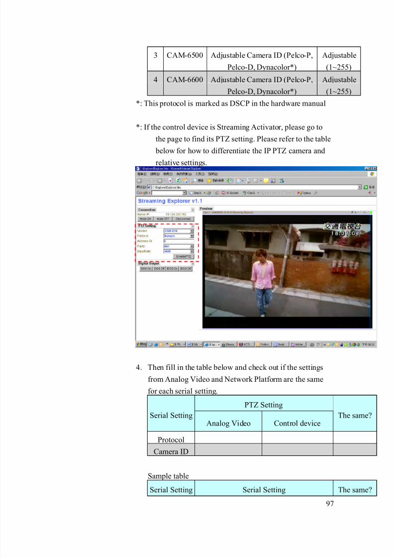
8/21/2019 IP Surveillance TroubleShooting Guide_V0.9
http://slidepdf.com/reader/full/ip-surveillance-troubleshooting-guidev09 99/347
97
3 CAM-6500 Adjustable Camera ID (Pelco-P,
Pelco-D, Dynacolor*)
Adjustable
(1~255)
4 CAM-6600 Adjustable Camera ID (Pelco-P,
Pelco-D, Dynacolor*)
Adjustable
(1~255)
*: This protocol is marked as DSCP in the hardware manual
*: If the control device is Streaming Activator, please go to
the page to find its PTZ setting. Please refer to the table
below for how to differentiate the IP PTZ camera and
relative settings.
4. Then fill in the table below and check out if the settings
from Analog Video and Network Platform are the same
for each serial setting.
PTZ Setting
Serial SettingAnalog Video Control device
The same?
Protocol
Camera ID
Sample table
Serial Setting Serial Setting The same?

8/21/2019 IP Surveillance TroubleShooting Guide_V0.9
http://slidepdf.com/reader/full/ip-surveillance-troubleshooting-guidev09 100/347
98
Analog Video Control device
Protocol Pelco-P Pelco-D No
Camera ID 1 1 Yes
7. If all the PTZ settings are the same in Analog Video and
Control device, this is not a PTZ Setting issue.
8. If any of the PTZ settings is not the same in Analog Video
and Control device, this is a PTZ Setting issue.
Solution:4. Follow the table below to adjust the setting of the Analog
Video and Network platform and make all the serial
settings the same.
Example:
.Before
Serial Setting
Serial Setting Analog Video Control device The same?
Protocol Pelco-P Pelco-D No
Camera ID 1 1 Yes
.After
Serial Setting
Serial SettingAnalog Video Network Platform
The same?
Protocol Pelco-P Pelco-P No
Camera ID 1 1 Yes
6-6.2.4 Inappropriate Analog Video – Camera ID setup
The problem is discussed in 6-3.1.3, please go there for details.

8/21/2019 IP Surveillance TroubleShooting Guide_V0.9
http://slidepdf.com/reader/full/ip-surveillance-troubleshooting-guidev09 101/347
99
6-6.2.5 Inappropriate Network platform - Serial type setup (if you areconnecting a video server to an analog camera)
The serial connection problem (might happen ONLY on video
server + analog cameras. If you are not using video servers +
analog cameras, please skip this section.
The serial connection type and serial physical connection have to
be right on both “Video server” and “Analog cameras” for PTZ
function to work. Thus we put them both.
Clarification:
2. Check out the serial connection type of the analog camera
and video servers and fill in the table below.
Serial Connection type No Description
Analog camera Video server
1 RS-485 * Default
2 RS-232 *
3 RS-422 *
*: Please refer to the analog camera’s hardware manual for
its serial connection type.
Sample table
Serial Connection type No Description
Analog camera Video server
1 RS-485 Default
2 RS-232
3 RS-422 Yes
7. If all the Serial Connection type is the same in Analog
Camera and Video server, this is not a Serial Connection
type. Then we go on next step to check out serial physical
connection.
8. If any of the Serial Connection type is not the same in
Analog Camera and Video server, this is a Serial
Connection type issue. Please go to solution to solve it

8/21/2019 IP Surveillance TroubleShooting Guide_V0.9
http://slidepdf.com/reader/full/ip-surveillance-troubleshooting-guidev09 102/347
100
first.
9. Follow the system diagram below for how does each serial
physical connection goes. (You might need to refer to
video server and speed dome’s hardware manual for it’s
serial pin details)
RS-485:
RS-232:
Data+ Data-
Data+ Data-
T+ R+ GND
T+ R+ GND

8/21/2019 IP Surveillance TroubleShooting Guide_V0.9
http://slidepdf.com/reader/full/ip-surveillance-troubleshooting-guidev09 103/347
101
10. If your connection is the same as above, this is not a serial
physical connection problem.
11. If your connection is not the same as above, this is a serial
physical connection problem.
Serial Connection Type Solution:
3. Refer to the previous table and adjust both connection type
to be the same (please follow the video server’s hardware
manual)
Example:
.Before
Serial Connection type No Description
Analog camera Video server
1 RS-485 Default2 RS-232
3 RS-422 Yes
.After
Serial Connection type No Description
Analog camera Video server
1 RS-485
T+ T- R+ R-
T+ T- R+ R-
8/21/2019 IP Surveillance TroubleShooting Guide_V0.9
http://slidepdf.com/reader/full/ip-surveillance-troubleshooting-guidev09 104/347
102
2 RS-232
3 RS-422 Yes Yes
Serial Physical Connection Solution:
3. Follow the serial physical connection diagram in
Clarification Step 4. Then correct them accordingly.
6-6.2.6 Inappropriate Network platform - Serial Physical Connection
(if you are connecting a video server to an analog camera)
The problem is discussed in 6-3.1.5, please go there for details.
.
6-6-3 Network block
The possible causes could be as below.
6-6.3.1 Inappropriate network port setup
The network port setting of the video server/IP camera should be
the same as the configuration in Streaming Activator, otherwise,
there might be no images coming out.
Clarification:
5. Login the camera and open streaming Activator to fill in
the port setting table below.
FunctionPort
Function
Video
Server/IP
camera
Streaming
Activator Default value
HTTP 80
Register 6000
Streaming 6002
Monitor
Control 6001
6. Check each function port and see if it is the same in both
video server/IP camera and the Streaming Activator
(below is a reference result)

8/21/2019 IP Surveillance TroubleShooting Guide_V0.9
http://slidepdf.com/reader/full/ip-surveillance-troubleshooting-guidev09 105/347
103
FunctionPort
Function
Video
Server/IP
camera
Streaming
Activator The same?
HTTP 80 80 YesRegister 6000 7000 NO
Monitor
Streaming 6002 7002 NO
7. If any of those are not the same, this is a port setting
problem.
8. If all these port setting are the same, this is not a port
setting problem.
Solution:
5. Adjust the setting of the streaming activator or video
server/IP camera to make the port setting is the same for
each port.
Example:
FunctionPort
Function
Video
Server/IP
camera
Streaming
Activator The same?
HTTP 80 80 Yes
Register 6000 7000
->6000
Yes
Monitor
Streaming 6002 7002
->6002
Yes
6-6-4 Management block
The possible causes could be as below.
6-6.4.1 Inappropriate baud rate, parity, stop bit setting
The problem is discussed in 6-3.1.1, please go there for details.
6-6.4.2 Inappropriate PTZ setting (protocol, camera ID)
The problem is discussed in 6-3.1.3, please go there for details.
.

8/21/2019 IP Surveillance TroubleShooting Guide_V0.9
http://slidepdf.com/reader/full/ip-surveillance-troubleshooting-guidev09 106/347
104
6-6-5 If problem not solved, how to report this
problem?
If the solution above can’t solve the problem, please gather the following
information and contact our sales. (Please see introduction about how to
contact).
6-6.5.1 Problem feedback table
Problem feedback table of login problem 1
Category Sub-category Description
Hard model Model number
Firmware Firmware version
Software model
Software
version
Serial Type
Connection diagram
Baud rate
Analog Video
Serial setting
Byte length, stop bit
HTTP port
Streaming port
Control port
Network
Platform
Register port
Serial Type
Connection diagram
Baud rate
Software PTZ
setting
Byte length, stop bit
HTTP port
Streaming port
Control port
Software port
setting
Register port
Other details
you find during
clarification

8/21/2019 IP Surveillance TroubleShooting Guide_V0.9
http://slidepdf.com/reader/full/ip-surveillance-troubleshooting-guidev09 107/347
105
Chapter. 7. Video Quality ProblemIn this Chapter, we will focus the problem that you can
1. Can login the video server/IP camera
2. Can monitor the image3. Video Quality is not good.
We will provide a diagnostic flow for customer to find out his problem type
within this problem category. Then we will examine the possible cause for each
problem type and find out the root cause and respective solutions.
7-1 Find out the possible cause
Please refer to the diagnostic flow to find out the problem type of the LoginProblem.
Then you can refer to next section for advanced clarification and
troubleshooting.
Check Item Remark
Step1 Check the Control Device
Step2 What is your video quality problem type?1. Image color is not true
2. Image blur
3. Image flashing
Step3 Do you find the same problem on a TV
connecting to the analog output?
Please make sure the
TV color display is ok
Step4 Refer to the section of each problem type
to do root cause clarification and find
respective solutions.
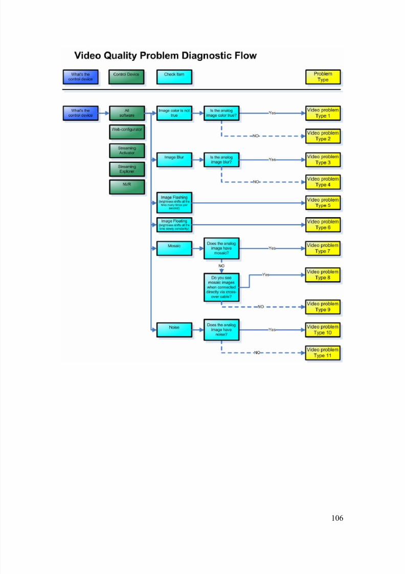
8/21/2019 IP Surveillance TroubleShooting Guide_V0.9
http://slidepdf.com/reader/full/ip-surveillance-troubleshooting-guidev09 108/347
106

8/21/2019 IP Surveillance TroubleShooting Guide_V0.9
http://slidepdf.com/reader/full/ip-surveillance-troubleshooting-guidev09 109/347
107
7-2 Video Quality problem Type 1
Refer to the cause clarification and respective solutions of each problem
type below. RED circled parts below indicating which building block mightcause this problem.
7-2-1 Image blockThe possible causes could be as below.
7-2.1.1 Inappropriate Network Platform – Video parameter
The in-correct image color might be resulted in-correct Video
Parameter setup in the network platform. This will result in
in-correct color rendering during image compression.
Network
Management
Storage
maging
Monitor
Management

8/21/2019 IP Surveillance TroubleShooting Guide_V0.9
http://slidepdf.com/reader/full/ip-surveillance-troubleshooting-guidev09 110/347
108
Clarification:
1. Login the video server/IP camera to check out its video
parameter and fill in the table as below.
2. Fill them in the video parameter table below. The table
below is divided by two parameter
a. Monitor type
b. Video Type of the Camera spec
Monitor TypeRecommended
parameter
Your setting
(Video server
/IP camera)
Video Type NTSC PAL
Hue 50 50
Brightness 55 55
Contrast 55 55
Saturation 85 85
3. If these video parameters are the same as recommended,
this is not a network platform – video parameter problem
4. If any of these video parameters are not the same as

8/21/2019 IP Surveillance TroubleShooting Guide_V0.9
http://slidepdf.com/reader/full/ip-surveillance-troubleshooting-guidev09 111/347
109
recommended, this is a network platform – video
parameter problem.
Solution:
1. Adjust the video parameter to make it exactly the same as
the one in recommended.
7-2.1.2 Inappropriate Analog Video – Video Type
Sometimes If the analog video output is not right, the in-correct
color issue might be caused by in-appropriate Video Type.
Clarification:
1. Login the video server/IP camera to check out its video
parameter and fill in the table as below.
Fill them in the video parameter table below.
Monitor TypeRecommended
parameter
Your setting
(Video server
/IP camera)
Video Type NTSC PAL
Hue 50 50
8/21/2019 IP Surveillance TroubleShooting Guide_V0.9
http://slidepdf.com/reader/full/ip-surveillance-troubleshooting-guidev09 112/347
110
Brightness 55 55
Contrast 55 55
Saturation 85 85
2. If these video parameters are the same as recommended,
this is not a network platform – video parameter problem
3. If any of these video parameters are not the same as
recommended, this is a network platform – video
parameter problem.
Solution:
1. Adjust the video parameter to make it exactly the same as
the one in recommended.
7-2-2 Management block Block
The possible causes could be as below.
7-2.2.1 Inappropriate Software Video Parameter setup
The in-correct image color might be resulted in-correct Software
video Parameter setup in the Streaming Activator. This will result
in in-correct color rendering during image compression.
Clarification:
1. Open Streaming Activator and go to “Camera Setup”
page.
2. Click “Preview” to connect to the video server / IP camera
and find the video parameter.
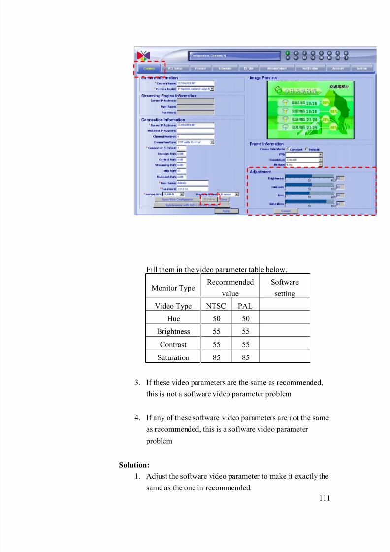
8/21/2019 IP Surveillance TroubleShooting Guide_V0.9
http://slidepdf.com/reader/full/ip-surveillance-troubleshooting-guidev09 113/347
111
Fill them in the video parameter table below.
Monitor Type
Recommended
value
Software
setting
Video Type NTSC PAL
Hue 50 50
Brightness 55 55
Contrast 55 55
Saturation 85 85
3. If these video parameters are the same as recommended,
this is not a software video parameter problem
4. If any of these software video parameters are not the same
as recommended, this is a software video parameter
problem
Solution:
1. Adjust the software video parameter to make it exactly the
same as the one in recommended.

8/21/2019 IP Surveillance TroubleShooting Guide_V0.9
http://slidepdf.com/reader/full/ip-surveillance-troubleshooting-guidev09 114/347
112
7-2-3 Other block
The possible causes could be as below.
7-2.3.1 Inappropriate – PC / TV monitor setting
The color rendering issue might be caused by incorrect monitor
you use.
Clarification:
1. Make sure the Video Parameter in Web-configurator is ok
first. (Follow the rules in 7-2-1, 7-2-3, 7-2-4)
2. Try to image on this monitor and see if the color is
correct?
3. If yes, this is not PC / TV monitor setting issue.
4. If not, this is PC / TV monitor setting issue.
Solution:
1. Adjust the video parameter of the PC / TC monitor
(following the monitor manual) to make the color right.
7-2-4 If problem not solved, how to report thisproblem?
If the solution above can’t solve the problem, please gather the following
information and contact our sales. (Please see introduction about how to
contact).
7-2.4.1 Problem feedback table
Problem feedback table of login problem 1
Category Sub-category Description
Hard model Model number
Firmware Firmware version
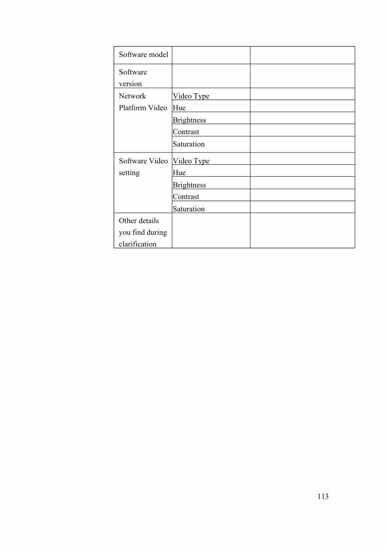
8/21/2019 IP Surveillance TroubleShooting Guide_V0.9
http://slidepdf.com/reader/full/ip-surveillance-troubleshooting-guidev09 115/347
113
Software model
Software
version
Video TypeHue
Brightness
Contrast
Network Platform Video
Saturation
Video Type
Hue
Brightness
Contrast
Software Video
setting
Saturation
Other details
you find during
clarification
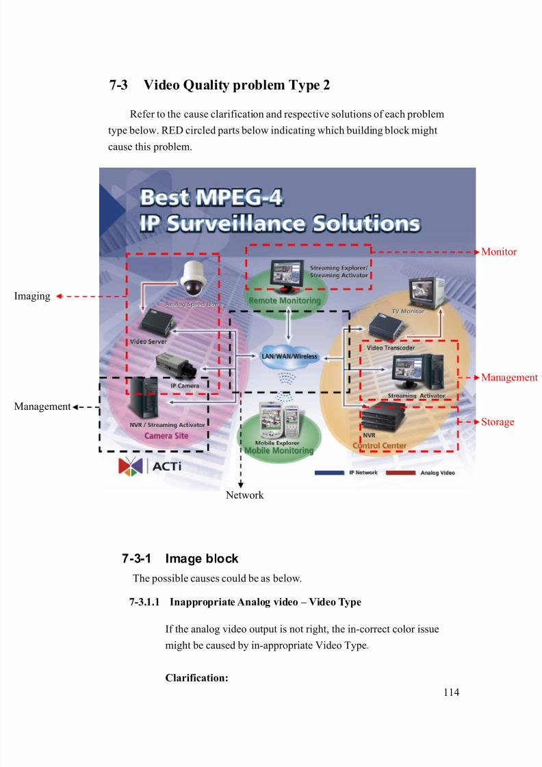
8/21/2019 IP Surveillance TroubleShooting Guide_V0.9
http://slidepdf.com/reader/full/ip-surveillance-troubleshooting-guidev09 116/347
114
7-3 Video Quality problem Type 2
Refer to the cause clarification and respective solutions of each problem
type below. RED circled parts below indicating which building block mightcause this problem.
7-3-1 Image block
The possible causes could be as below.
7-3.1.1 Inappropriate Analog video – Video Type
If the analog video output is not right, the in-correct color issue
might be caused by in-appropriate Video Type.
Clarification:
Network
Management
Storage
maging
Monitor
Management

8/21/2019 IP Surveillance TroubleShooting Guide_V0.9
http://slidepdf.com/reader/full/ip-surveillance-troubleshooting-guidev09 117/347
115
1. Check out your local TV video type (NTSC/PAL) and the
IP camera / analog camera’s video type (NTSC/PAL)
Video Type TV
Analog
camera/IP
camera
The same?
NTSC
PAL
2. Check if the TV video type is the same as the IP camera /
analog camera?
Example
Video Type TV
Analog
camera/IP
camera
The same?
NTSC ●
PAL ● No
3. If the video type is the same, this is not an analog video –
video type problem.
4. If the video type is not the same, this is an analog video –
video type problem.
Solution:
1. Replace the current camera with a right video type camera.
Example:
Before:
Video Type TV
Analog
camera/IP
camera
The same?
NTSC ●
PAL ● No
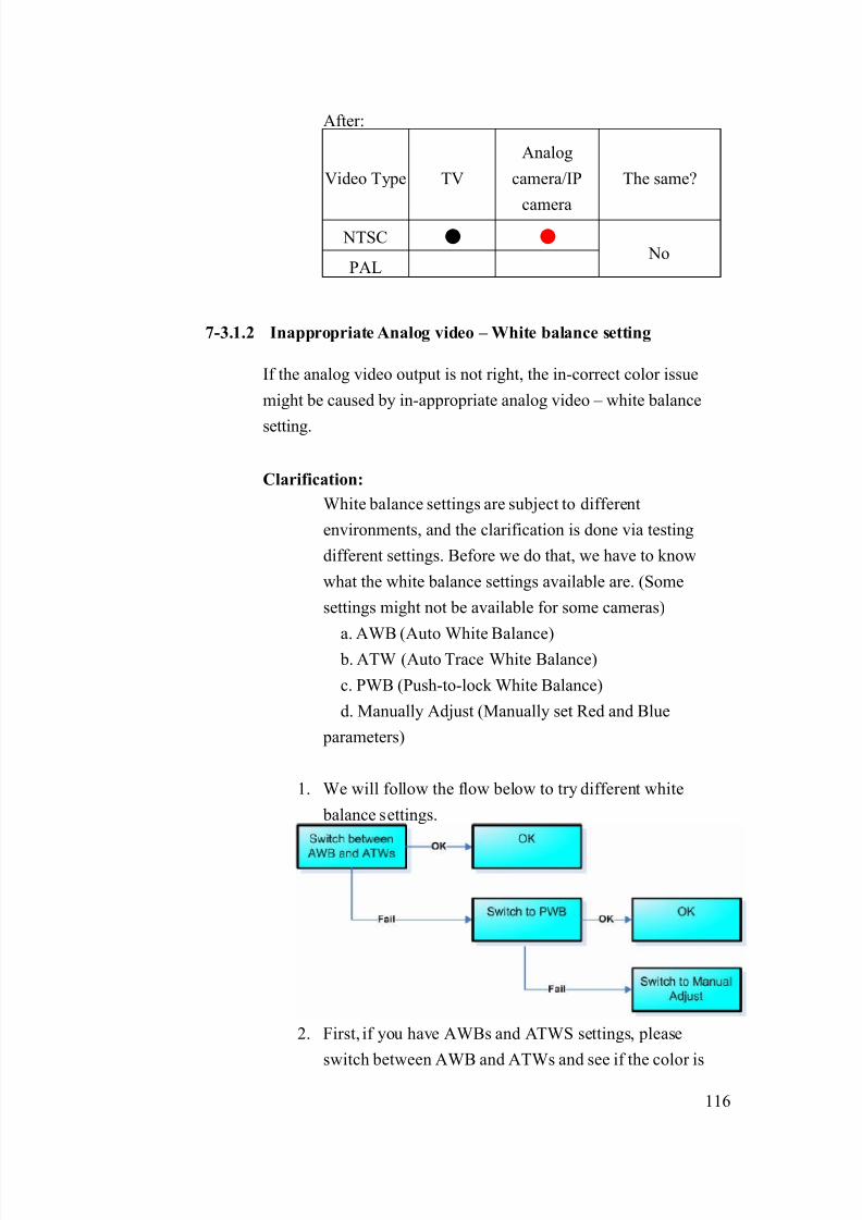
8/21/2019 IP Surveillance TroubleShooting Guide_V0.9
http://slidepdf.com/reader/full/ip-surveillance-troubleshooting-guidev09 118/347
116
After:
Video Type TV
Analog
camera/IP
camera
The same?
NTSC ● ●
PAL No
7-3.1.2 Inappropriate Analog video – White balance setting
If the analog video output is not right, the in-correct color issue
might be caused by in-appropriate analog video – white balance
setting.
Clarification:
White balance settings are subject to different
environments, and the clarification is done via testing
different settings. Before we do that, we have to know
what the white balance settings available are. (Some
settings might not be available for some cameras)
a. AWB (Auto White Balance) b. ATW (Auto Trace White Balance)
c. PWB (Push-to-lock White Balance)
d. Manually Adjust (Manually set Red and Blue
parameters)
1. We will follow the flow below to try different white
balance settings.
2. First, if you have AWBs and ATWS settings, please
switch between AWB and ATWs and see if the color is

8/21/2019 IP Surveillance TroubleShooting Guide_V0.9
http://slidepdf.com/reader/full/ip-surveillance-troubleshooting-guidev09 119/347
117
correct. You can refer to the table for what white balance
setting a camera has. (Note: this only includes ACTi IP
cameras, for other analog cameras, you have to refer to
their hardware manual respectively)
Camera Series AWB ATW PWB Manual
Adjust
CAM-5100 ● ●
CAM-5200 ● ●
CAM-5300 ● ●
CAM-5130 ● ● ●
CAM-5140 ● ● ●
CAM-5150 ● ● ●
CAM-7100 ● ●
CAM-6100 ● ● ● ●
CAM-6200 ● ● ●
CAM-6500 ● ● ● ●
CAM-6600 ● ● ● ●
3. If step2 fail, switch the white balance to “PWB” and see if
the color is correct. Please refer the following procedure
for PWB setting.
a. Use a white paper to fully cover the camera’s lens
b. Switch to PWB setting
c. Make camera to sync white balance setting with
current paper (please see respective hardware manual)d. Remove the white paper
e. Check if the color is correct now.
4. If step3 fail, switch the white balance to “Manual Adjust”
for color correction. (please see respective hardware
manual)
Solution:
8/21/2019 IP Surveillance TroubleShooting Guide_V0.9
http://slidepdf.com/reader/full/ip-surveillance-troubleshooting-guidev09 120/347
118
The solution is done during the clarification stage above.
7-3-2 If problem not solved, how to report this
problem?If the solution above can’t solve the problem, please gather the following
information and contact our sales. (Please see introduction about how to
contact).
7-3.2.1 Problem feedback table
Problem feedback table of login problem 1
Category Sub-category Description
Hard model Model number
Firmware Firmware version
Video Type
White balance setting
Analog Video
On-site situation
Other details
you find during
clarification

8/21/2019 IP Surveillance TroubleShooting Guide_V0.9
http://slidepdf.com/reader/full/ip-surveillance-troubleshooting-guidev09 121/347
119
7-4 Video Quality problem Type 3
Refer to the cause clarification and respective solutions of each problem
type below. RED circled parts below indicating which building block mightcause this problem.
7-4-1 Image block
The possible causes could be as below.
7-4.1.1 Inappropriate Analog Video – Focus
If the focus is not right, the image is likely to be blurred.
Clarification:
1. First, we have to what kind of camera you are using
Network
Management
Storage
maging
Monitor
Management

8/21/2019 IP Surveillance TroubleShooting Guide_V0.9
http://slidepdf.com/reader/full/ip-surveillance-troubleshooting-guidev09 122/347
120
2. Then refer to the table below for adjusting the focus and
see if the image becomes clear.
Camera Type Manually
adjust the lens
Adjust via
software
remotely
Box / Dome camera
with Fixed lens
●*
Box / Dome camera
with varifocal lens
●*
Zoom lens camera ●**
Speed dome camera ●**
*. Please refer to lens’ hardware manual for focus adjust**. Please refer to IP camera’s hardware manual to
adjust the focus.
3. If adjusting the focus doesn’t solve this problem, this is
not a focus problem.
4. If adjusting the focus solves the problem, please check the
table for further action.Camera Type Problem Fixed Adjust OSD
setting
Box / Dome camera
with Fixed lens
●
Box / Dome camera
with varifocal lens
●
Zoom lens camera ●*
(go to Step5)
Speed dome camera ●*
(go to Step5)
5. This steps is for cameras supporting OSD function
a. zoom lens camera
b. speed dome camera
Please make sure the focus setting in the OSD menu is set
to “Auto”. You can refer to respective hardware manual
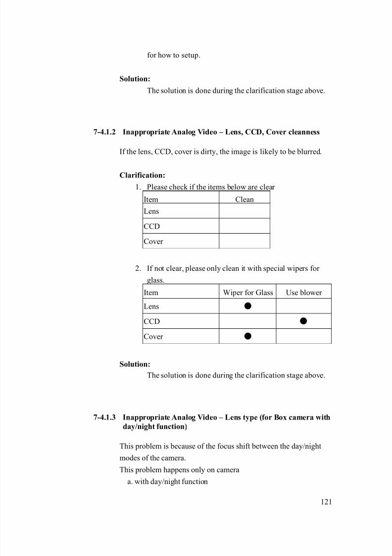
8/21/2019 IP Surveillance TroubleShooting Guide_V0.9
http://slidepdf.com/reader/full/ip-surveillance-troubleshooting-guidev09 123/347
121
for how to setup.
Solution:
The solution is done during the clarification stage above.
7-4.1.2 Inappropriate Analog Video – Lens, CCD, Cover cleanness
If the lens, CCD, cover is dirty, the image is likely to be blurred.
Clarification:
1. Please check if the items below are clear
Item Clean
Lens
CCD
Cover
2. If not clear, please only clean it with special wipers for
glass.
Item Wiper for Glass Use blower
Lens ●
CCD ●
Cover ●
Solution:
The solution is done during the clarification stage above.
7-4.1.3 Inappropriate Analog Video – Lens type (for Box camera with
day/night function)
This problem is because of the focus shift between the day/night
modes of the camera.
This problem happens only on camera
a. with day/night function

8/21/2019 IP Surveillance TroubleShooting Guide_V0.9
http://slidepdf.com/reader/full/ip-surveillance-troubleshooting-guidev09 124/347
122
b. without lens built-in (lens is bought in addition to the camera)
please see the table below
Day/Night cameras
Camera Type Model No.
ossible lens type
problem
CAM-5120 Yes
CAM-5220 Yes
Box camera
CAM-5320 Yes
CAM-5140 -Zoom lens
camera CAM-5150 -
CAM-6110
CAM-6120-
CAM-6220
CAM-6230 -
CAM-6510
CAM-6520 -
Speed dome
CAM-6610CAM-6620
-
Clarification:
1. If you are using the camera above marked with this
possible les type problem, then you have to check the lens
type you use.
Focus situationItem
In either Day / Night
situation
In switching between
Day / Night situation
Normal Lens ●
IR correct ●
2. If you are using IR correct lens, this is not an analog
video – lens type problem.
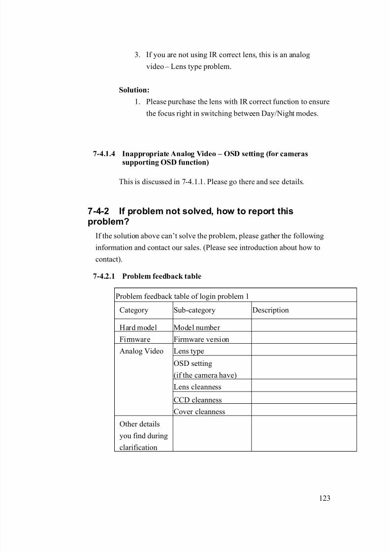
8/21/2019 IP Surveillance TroubleShooting Guide_V0.9
http://slidepdf.com/reader/full/ip-surveillance-troubleshooting-guidev09 125/347
123
3. If you are not using IR correct lens, this is an analog
video – Lens type problem.
Solution:
1. Please purchase the lens with IR correct function to ensure
the focus right in switching between Day/Night modes.
7-4.1.4 Inappropriate Analog Video – OSD setting (for camerassupporting OSD function)
This is discussed in 7-4.1.1. Please go there and see details.
7-4-2 If problem not solved, how to report thisproblem?
If the solution above can’t solve the problem, please gather the following
information and contact our sales. (Please see introduction about how to
contact).
7-4.2.1 Problem feedback table
Problem feedback table of login problem 1
Category Sub-category Description
Hard model Model number
Firmware Firmware version
Lens type
OSD setting
(if the camera have)
Lens cleanness
CCD cleanness
Analog Video
Cover cleanness
Other details
you find during
clarification

8/21/2019 IP Surveillance TroubleShooting Guide_V0.9
http://slidepdf.com/reader/full/ip-surveillance-troubleshooting-guidev09 126/347
124
7-5 Video Quality problem Type 4
Refer to the cause clarification and respective solutions of each problem
type below. RED circled parts below indicating which building block mightcause this problem.
7-5-1 Image block
The possible causes could be as below.
7-5.1.1 Inappropriate Network Platform – Bit rate, frame rate
The video quality is determined by 3 parameters
a. Resolution
b. Bit rate
c. frame rate
Network
Management
Storage
maging
Monitor
Management
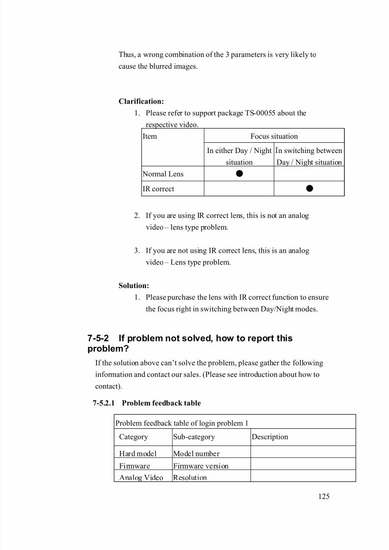
8/21/2019 IP Surveillance TroubleShooting Guide_V0.9
http://slidepdf.com/reader/full/ip-surveillance-troubleshooting-guidev09 127/347
125
Thus, a wrong combination of the 3 parameters is very likely to
cause the blurred images.
Clarification:
1. Please refer to support package TS-00055 about the
respective video.
Focus situationItem
In either Day / Night
situation
n switching between
Day / Night situation
Normal Lens ●
IR correct ●
2. If you are using IR correct lens, this is not an analog
video – lens type problem.
3. If you are not using IR correct lens, this is an analog
video – Lens type problem.
Solution:1. Please purchase the lens with IR correct function to ensure
the focus right in switching between Day/Night modes.
7-5-2 If problem not solved, how to report thisproblem?
If the solution above can’t solve the problem, please gather the following
information and contact our sales. (Please see introduction about how to
contact).
7-5.2.1 Problem feedback table
Problem feedback table of login problem 1
Category Sub-category Description
Hard model Model number
Firmware Firmware version
Analog Video Resolution

8/21/2019 IP Surveillance TroubleShooting Guide_V0.9
http://slidepdf.com/reader/full/ip-surveillance-troubleshooting-guidev09 128/347
126
Frame rate
Bit rate
Other details
you find during
clarification

8/21/2019 IP Surveillance TroubleShooting Guide_V0.9
http://slidepdf.com/reader/full/ip-surveillance-troubleshooting-guidev09 129/347
127
7-6 Video Quality problem Type 5
Refer to the cause clarification and respective solutions of each problem
type below. RED circled parts below indicating which building block mightcause this problem.
7-6-1 Image block
The possible causes could be as below.
7-6.1.1 Inappropriate Analog Video – Video Type
The video flash is likely to be caused by inappropriate Video Type.
Clarification:
1. Check out your local TV video type (NTSC/PAL) and the
IP camera / analog camera’s video type (NTSC/PAL)
Network
Management
Storage
maging
Monitor
Management
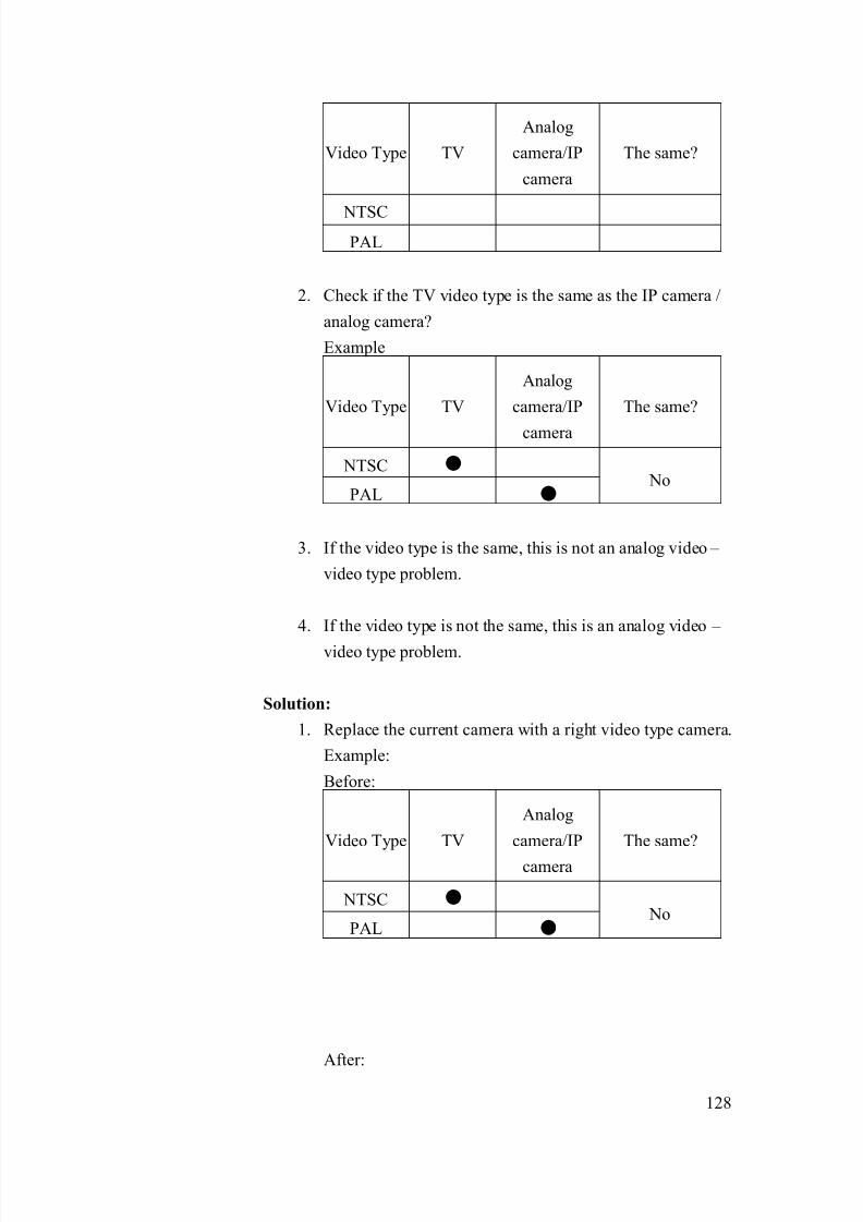
8/21/2019 IP Surveillance TroubleShooting Guide_V0.9
http://slidepdf.com/reader/full/ip-surveillance-troubleshooting-guidev09 130/347
128
Video Type TV
Analog
camera/IP
camera
The same?
NTSC
PAL
2. Check if the TV video type is the same as the IP camera /
analog camera?
Example
Video Type TV
Analog
camera/IP
camera
The same?
NTSC ●
PAL ● No
3. If the video type is the same, this is not an analog video –
video type problem.
4. If the video type is not the same, this is an analog video –
video type problem.
Solution:
1. Replace the current camera with a right video type camera.
Example:
Before:
Video Type TV
Analog
camera/IP
camera
The same?
NTSC ●
PAL ● No
After:

8/21/2019 IP Surveillance TroubleShooting Guide_V0.9
http://slidepdf.com/reader/full/ip-surveillance-troubleshooting-guidev09 131/347
129
Video Type TV
Analog
camera/IP
camera
The same?
NTSC ● ●
PAL No
7-6-2 If problem not solved, how to report thisproblem?
If the solution above can’t solve the problem, please gather the following
information and contact our sales. (Please see introduction about how to
contact).
7-6.2.1 Problem feedback table
Problem feedback table of login problem 1
Category Sub-category Description
Hard model Model number
Firmware Firmware version
Analog Video
Serial setting
Video Type
TV video typeEnvironment
condition Electric frequency
Other details
you find during
clarification
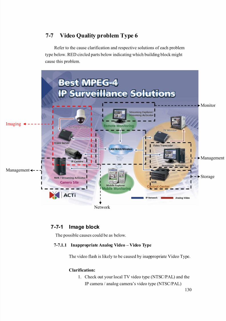
8/21/2019 IP Surveillance TroubleShooting Guide_V0.9
http://slidepdf.com/reader/full/ip-surveillance-troubleshooting-guidev09 132/347
130
7-7 Video Quality problem Type 6
Refer to the cause clarification and respective solutions of each problem
type below. RED circled parts below indicating which building block mightcause this problem.
7-7-1 Image block
The possible causes could be as below.
7-7.1.1 Inappropriate Analog Video – Video Type
The video flash is likely to be caused by inappropriate Video Type.
Clarification:
1. Check out your local TV video type (NTSC/PAL) and the
IP camera / analog camera’s video type (NTSC/PAL)
Network
Management
Storage
maging
Monitor
Management

8/21/2019 IP Surveillance TroubleShooting Guide_V0.9
http://slidepdf.com/reader/full/ip-surveillance-troubleshooting-guidev09 133/347
131
Video Type TV
Analog
camera/IP
camera
The same?
NTSC
PAL
2. Check if the TV video type is the same as the IP camera /
analog camera?
Example
Video Type TV
Analog
camera/IP
camera
The same?
NTSC ●
PAL ● No
3. If the video type is the same, this is not an analog video –
video type problem.
4. If the video type is not the same, this is an analog video –
video type problem.
Solution:
1. Replace the current camera with a right video type camera.
Example:
Before:
Video Type TV
Analog
camera/IP
camera
The same?
NTSC ●
PAL ● No
After:
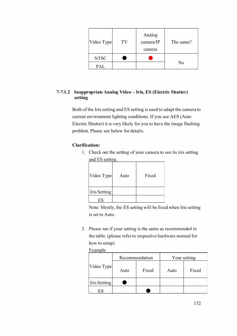
8/21/2019 IP Surveillance TroubleShooting Guide_V0.9
http://slidepdf.com/reader/full/ip-surveillance-troubleshooting-guidev09 134/347
132
Video Type TV
Analog
camera/IP
camera
The same?
NTSC ● ●
PAL No
7-7.1.2 Inappropriate Analog Video – Iris, ES (Electric Shutter)
setting
Both of the Iris setting and ES setting is used to adapt the camera to
current environment lighting conditions. If you use AES (AutoElectric Shutter) it is very likely for you to have the image flashing
problem. Please see below for details.
Clarification:
1. Check out the setting of your camera to see its iris setting
and ES setting.
Video Type Auto Fixed
Iris Setting
ES
Note: Mostly, the ES setting will be fixed when Iris setting
is set to Auto.
2. Please see if your setting is the same as recommended in
the table. (please refer to respective hardware manual for
how to setup)
Example
Recommendation Your setting
Video TypeAuto Fixed Auto Fixed
Iris Setting ●
ES ●
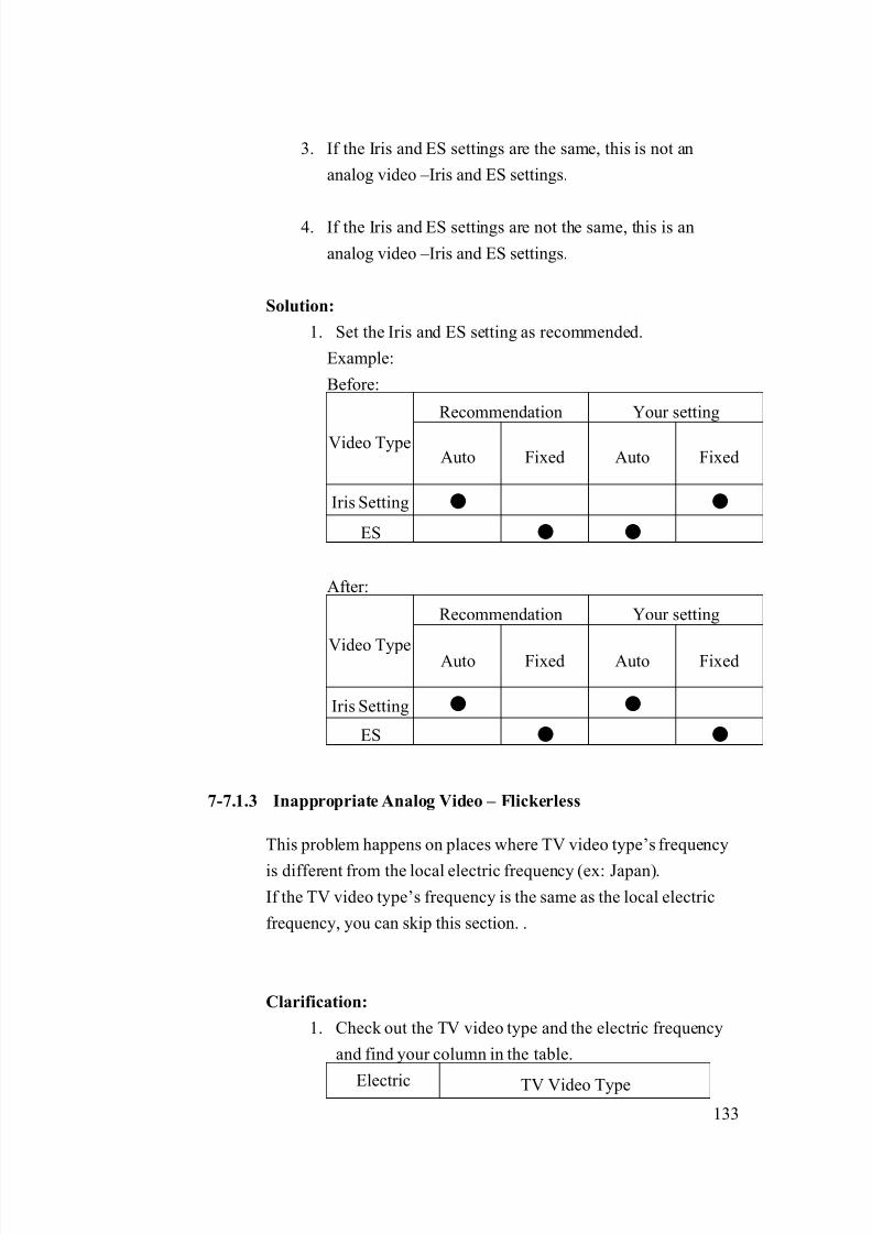
8/21/2019 IP Surveillance TroubleShooting Guide_V0.9
http://slidepdf.com/reader/full/ip-surveillance-troubleshooting-guidev09 135/347
133
3. If the Iris and ES settings are the same, this is not an
analog video –Iris and ES settings.
4. If the Iris and ES settings are not the same, this is an
analog video –Iris and ES settings.
Solution:
1. Set the Iris and ES setting as recommended.
Example:
Before:
Recommendation Your setting
Video TypeAuto Fixed Auto Fixed
Iris Setting ● ●
ES ● ●
After:
Recommendation Your setting
Video Type Auto Fixed Auto Fixed
Iris Setting ● ●
ES ● ●
7-7.1.3 Inappropriate Analog Video – Flickerless
This problem happens on places where TV video type’s frequency
is different from the local electric frequency (ex: Japan).
If the TV video type’s frequency is the same as the local electric
frequency, you can skip this section. .
Clarification:
1. Check out the TV video type and the electric frequency
and find your column in the table.
Electric TV Video Type

8/21/2019 IP Surveillance TroubleShooting Guide_V0.9
http://slidepdf.com/reader/full/ip-surveillance-troubleshooting-guidev09 136/347
134
Frequency NTSC PAL
50Hz A B
60Hz C D
2. If you are in column B, C, this is not a Flickerless
problem
3. If you are in column A, D, this is a Flickerless problem.
Solution:
1. Please refer to the table for solution for each camera type
in different kind of video type environment.
NTSC PALCamera Series
Enable
Flickerless
Set ES
fixed at
1/100sec
Enable
Flickerless
Set ES
fixed at
1/120sec
CAM-5100 ● ●
CAM-5200 ● ●
Camera
with
Flickerless
function CAM-5300 ● ●
CAM-5130 ● ●
CAM-5140 ● ●
CAM-5150 ● ●
CAM-7100 ● ●
CAM-6100 ● ●
CAM-6200 ● ●
CAM-6500 ● ●
Camera
with
Flickerless
function
CAM-6600 ● ●

8/21/2019 IP Surveillance TroubleShooting Guide_V0.9
http://slidepdf.com/reader/full/ip-surveillance-troubleshooting-guidev09 137/347
135
7-7-2 If problem not solved, how to report this
problem?
If the solution above can’t solve the problem, please gather the following
information and contact our sales. (Please see introduction about how to
contact).
7-7.2.1 Problem feedback table
Problem feedback table of login problem 1
Category Sub-category Description
Hard model Model number
Firmware Firmware version
Video Type
Iris setting
ES setting
Analog Video
Serial setting
Flickerless setting
TV video type
Electric frequency
Environment
condition
Local lighting condition
Other details
you find during
clarification

8/21/2019 IP Surveillance TroubleShooting Guide_V0.9
http://slidepdf.com/reader/full/ip-surveillance-troubleshooting-guidev09 138/347
136
7-8 Video Quality problem Type 7
Refer to the cause clarification and respective solutions of each problem
type below. RED circled parts below indicating which building block mightcause this problem.
7-8-1 Image block
The possible causes could be as below.
7-8.1.1 Unknown problem
It is rare to see mosaic at the analog output. The possible cause
could be CCD or Camera DSP mal-function. Please capture a
picture of the analog mosaic images and send it back.
Network
Management
Storage
maging
Monitor
Management
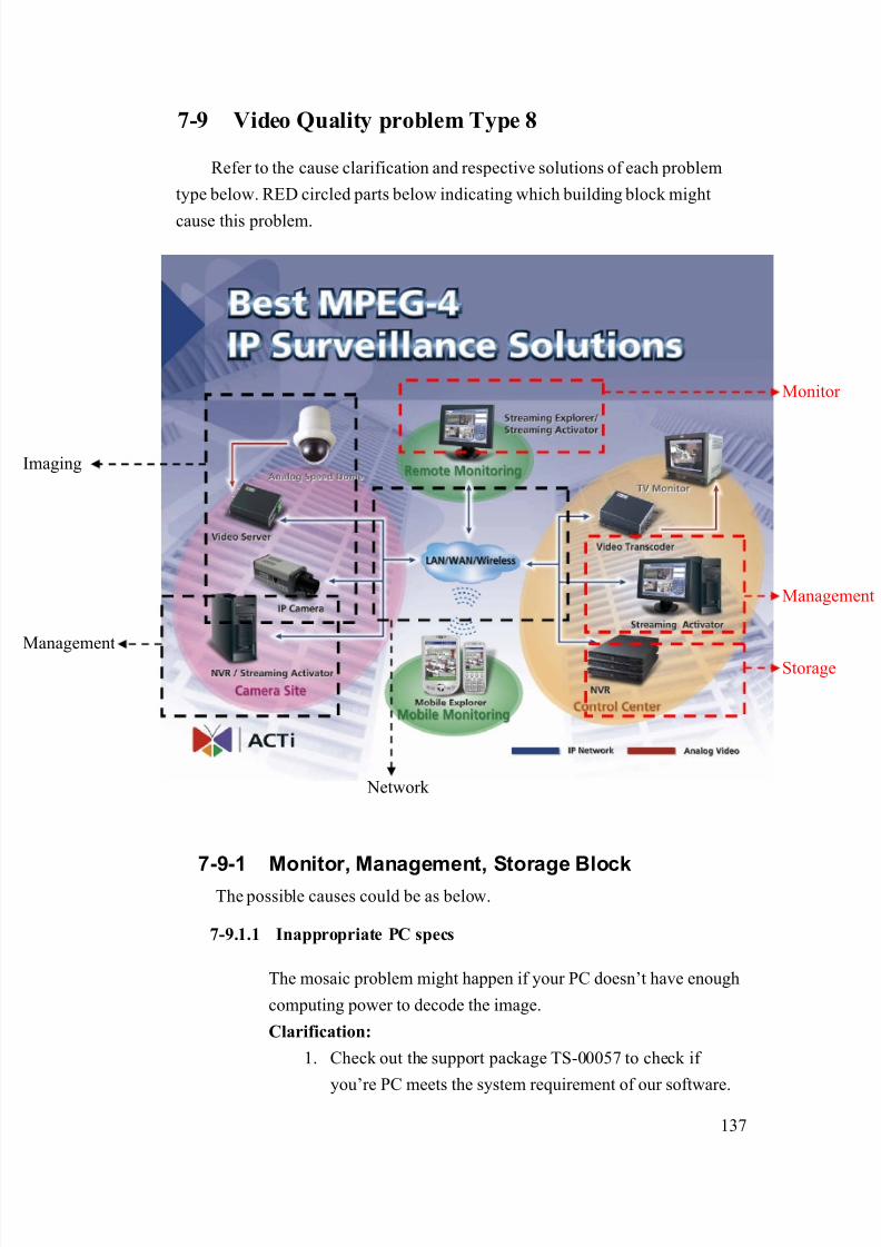
8/21/2019 IP Surveillance TroubleShooting Guide_V0.9
http://slidepdf.com/reader/full/ip-surveillance-troubleshooting-guidev09 139/347
137
7-9 Video Quality problem Type 8
Refer to the cause clarification and respective solutions of each problem
type below. RED circled parts below indicating which building block might
cause this problem.
7-9-1 Monitor, Management, Storage BlockThe possible causes could be as below.
7-9.1.1 Inappropriate PC specs
The mosaic problem might happen if your PC doesn’t have enough
computing power to decode the image.
Clarification:
1. Check out the support package TS-00057 to check if
you’re PC meets the system requirement of our software.
Network
Management
Storage
maging
Monitor
Management

8/21/2019 IP Surveillance TroubleShooting Guide_V0.9
http://slidepdf.com/reader/full/ip-surveillance-troubleshooting-guidev09 140/347
138
2. If your system meets the requirement, this is not an
inappropriate PC spec problem.
3. If your system fails to meet to requirement, this is an
inappropriate PC spec problem.
Solution:
1. Please follow the system requirement in support package
TS-00057 to adjust your PC spec.
7-9-2 If problem not solved, how to report this
problem?
If the solution above can’t solve the problem, please gather the following
information and contact our sales. (Please see introduction about how to
contact).
7-9.2.1 Problem feedback table
Problem feedback table of login problem 1
Category Sub-category Description
Hard model Model number
Firmware Firmware version
Software model
Software
version
Network connection
Connection(LAN or WAN or
cross-over)
CPU
RAM
Motherboard FSB
VGA card
PC spec
Register port
Other details

8/21/2019 IP Surveillance TroubleShooting Guide_V0.9
http://slidepdf.com/reader/full/ip-surveillance-troubleshooting-guidev09 141/347
139
you find during
clarification

8/21/2019 IP Surveillance TroubleShooting Guide_V0.9
http://slidepdf.com/reader/full/ip-surveillance-troubleshooting-guidev09 142/347
140
7-10 Video Quality problem Type 9
Refer to the cause clarification and respective solutions of each problem
type below. RED circled parts below indicating which building block mightcause this problem.
7-10-1 Monitor, Management, Storage block
The possible causes could be as below.
7-10.1.1 Too many con-current users
The mosaic problem might happen if there are too many
con-current users connecting to the video server/IP camera and
cause it overload.
Clarification:
1. Please fill in the table below about the video setting and
Network
Management
Storage
maging
Monitor
Management
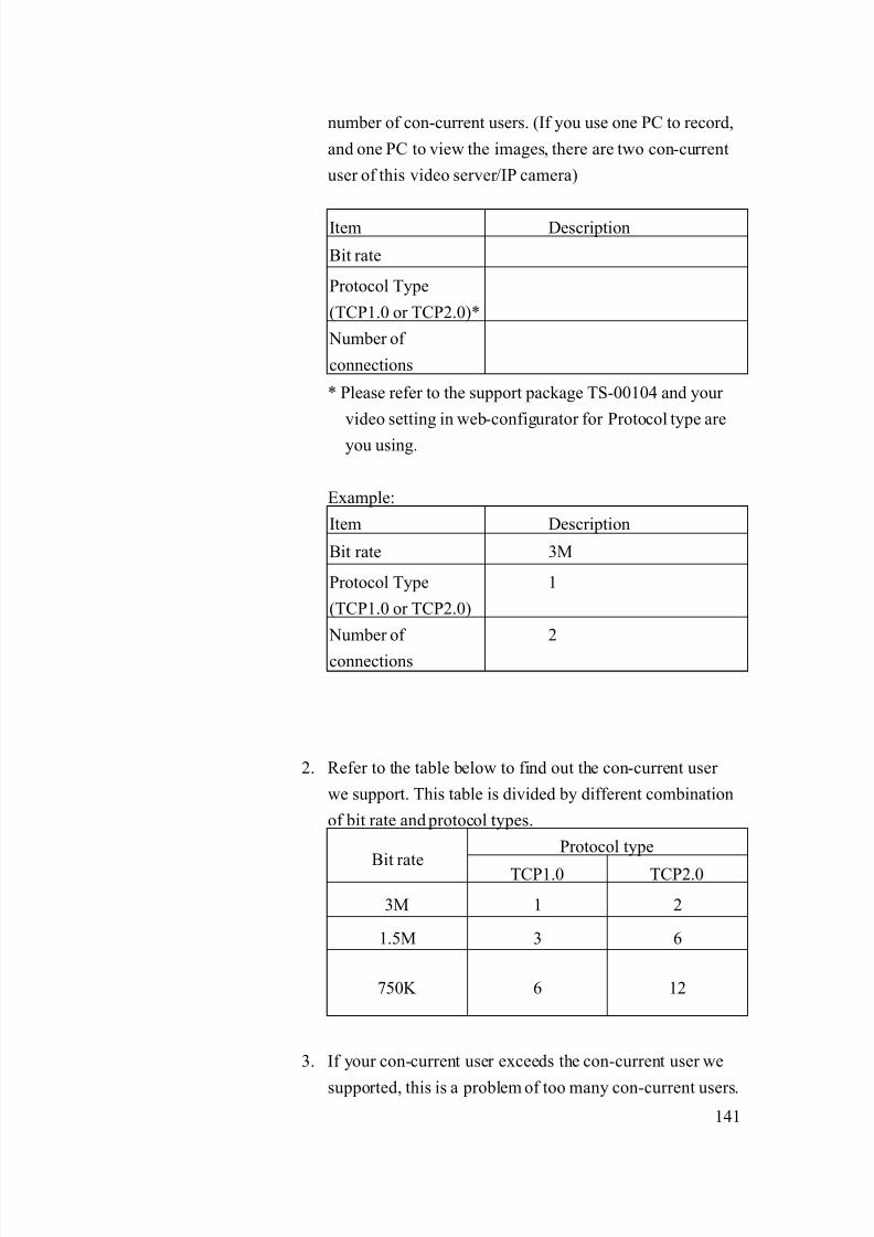
8/21/2019 IP Surveillance TroubleShooting Guide_V0.9
http://slidepdf.com/reader/full/ip-surveillance-troubleshooting-guidev09 143/347
141
number of con-current users. (If you use one PC to record,
and one PC to view the images, there are two con-current
user of this video server/IP camera)
Item Description
Bit rate
Protocol Type
(TCP1.0 or TCP2.0)*
Number of
connections
* Please refer to the support package TS-00104 and your
video setting in web-configurator for Protocol type are
you using.
Example:
Item Description
Bit rate 3M
Protocol Type
(TCP1.0 or TCP2.0)
1
Number of
connections
2
2. Refer to the table below to find out the con-current user
we support. This table is divided by different combination
of bit rate and protocol types.
Protocol type
Bit rate TCP1.0 TCP2.0
3M 1 2
1.5M 3 6
750K 6 12
3. If your con-current user exceeds the con-current user we
supported, this is a problem of too many con-current users.

8/21/2019 IP Surveillance TroubleShooting Guide_V0.9
http://slidepdf.com/reader/full/ip-surveillance-troubleshooting-guidev09 144/347
142
4. If your con-current user doesn’t exceed the con-current
user we supported, this is a problem of too many
con-current users.
Solution:
1. There are two types of solution to solve this problem.
a. Decrease the bit rate to increase the con-current
user (Note: Decrease the bit rate might cause the
video quality to decrease as well)
b. Decrease the number of con-current user. (decrease
the number of user by changing system design)
7-10-2 Network block
The possible causes could be as below.
7-10.2.1 Insufficient/instable network bandwidth
Insufficient network bandwidth or instable network bandwidth is
very likely to cause the network package to be lost during
transmission. Too many drop network packages will cause mosaic.
Clarification:
1. Because the mosaic disappears when connecting via
cross-over cable. The problem definition will be as below
Connection Type Mosaic Normal
Previous network ●
Cross-over ●
2. Please bring the test result to your MIS or the one build-up
your network infrastructure and ask him to clarify if the
network bandwidth is ok and stable.
Item Description
Bit rate 3M
Protocol Type
(TCP1.0 or TCP2.0)
1
Number of 2

8/21/2019 IP Surveillance TroubleShooting Guide_V0.9
http://slidepdf.com/reader/full/ip-surveillance-troubleshooting-guidev09 145/347
143
connections
Connection Type Mosaic Normal
Previous network ●
Cross-over ●
3. If yes, this is not an insufficient/instable network
bandwidth problem.
4. If not, this is an insufficient/instable network bandwidth
problem.
Solution:
1. Because the network involves too many issues, it’s very
hard for ACTi to provide you to solution. Thus, please ask
your MIS or the one build up your network infrastructure
about how to solve this problem.
7-10-3 If problem not solved, how to report this
problem?If the solution above can’t solve the problem, please gather the following
information and contact our sales. (Please see introduction about how to
contact).
7-10.3.1 Problem feedback table
Problem feedback table of login problem 1
Category Sub-category Description
Product model Model number
Firmware Firmware version
Bit rate
Protocol type
Video Server
Gateway
Software Number of con-current
user
Network Network diagram

8/21/2019 IP Surveillance TroubleShooting Guide_V0.9
http://slidepdf.com/reader/full/ip-surveillance-troubleshooting-guidev09 146/347
144
deployment Respective setting of
switch / routers.

8/21/2019 IP Surveillance TroubleShooting Guide_V0.9
http://slidepdf.com/reader/full/ip-surveillance-troubleshooting-guidev09 147/347
145
7-11 Video Quality problem Type 10
Refer to the cause clarification and respective solutions of each problem
type below. RED circled parts below indicating which building block mightcause this problem.
7-11-1 Image block
The possible causes could be as below.
7-11.1.1 Inappropriate Analog Video – Low lighting environment
If the environment lighting is now, it is very likely to cause noise to
happen.
Clarification:
1. Switch the IP camera/analog camera to a place where
Network
Management
Storage
maging
Monitor
Management
8/21/2019 IP Surveillance TroubleShooting Guide_V0.9
http://slidepdf.com/reader/full/ip-surveillance-troubleshooting-guidev09 148/347
146
lighting condition is ok and see if there’s still noises
2. If not, this is Analog video –low lighting environment
problem
3. If yes, this is not Analog Video – Low lighting
environment problem.
Solution:
1. To solve this issue, you have to increase the lighting
condition in the environment.
7-11.1.2 Inappropriate Analog Video – Day/Night mode switch
This section is for cameras with Day/Night function only.
Sometimes the noises is caused by inappropriate mode.
Clarification:
1. Switch the IP camera/analog camera to Night mode and
see if the noise disappears.
2. If yes, this is Analog Video – Day/Night mode switch
problem.
3. If not, this is not Analog Video – Day/Night mode switch
problem.
Solution:
1. Please refer to camera’s hardware manual for how toa. Switch to Night mode
b. Enable the camera to switch automatically between
day/night mode.
7-11.1.3 Inappropriate Analog Video – AGC (Auto Gain Control)
Sometimes the AGC will cause the camera to have noises. But only
if the lighting condition of your environment is always sufficient,
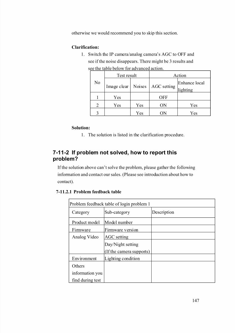
8/21/2019 IP Surveillance TroubleShooting Guide_V0.9
http://slidepdf.com/reader/full/ip-surveillance-troubleshooting-guidev09 149/347
147
otherwise we would recommend you to skip this section.
Clarification:
1. Switch the IP camera/analog camera’s AGC to OFF and
see if the noise disappears. There might be 3 results and
see the table below for advanced action.
Test result Action
NoImage clear Noises AGC setting
Enhance local
lighting
1 Yes OFF
2 Yes Yes ON Yes
3 Yes ON Yes
Solution:
1. The solution is listed in the clarification procedure.
7-11-2 If problem not solved, how to report thisproblem?
If the solution above can’t solve the problem, please gather the following
information and contact our sales. (Please see introduction about how tocontact).
7-11.2.1 Problem feedback table
Problem feedback table of login problem 1
Category Sub-category Description
Product model Model number
Firmware Firmware version
AGC settingAnalog Video
Day/Night setting
(If the camera supports)
Environment Lighting condition
Others
information you
find during test

8/21/2019 IP Surveillance TroubleShooting Guide_V0.9
http://slidepdf.com/reader/full/ip-surveillance-troubleshooting-guidev09 150/347
148
7-12 Video Quality problem Type 11
Refer to the cause clarification and respective solutions of each problem
type below. RED circled parts below indicating which building block mightcause this problem.
7-12-1 Other
The possible causes could be as below.
7-12.1.1 Unknown
It is rare to see images with noise while the video servers/IP
cameras’ analog output has no noise. Please prepare a snapshot of
the analog image and a recording file of the digital images
Network
Management
Storage
maging
Monitor
Management

8/21/2019 IP Surveillance TroubleShooting Guide_V0.9
http://slidepdf.com/reader/full/ip-surveillance-troubleshooting-guidev09 151/347
149
Problem feedback table of login problem 1
Category Sub-category Description
Product model Model number
Firmware Firmware version
Software model
Software
version
Video Server A snapshot of analog
image
Software Video clip of the digital
images
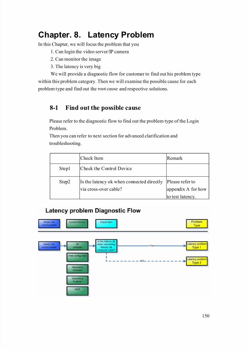
8/21/2019 IP Surveillance TroubleShooting Guide_V0.9
http://slidepdf.com/reader/full/ip-surveillance-troubleshooting-guidev09 152/347
150
Chapter. 8. Latency ProblemIn this Chapter, we will focus the problem that you
1. Can login the video server/IP camera
2. Can monitor the image3. The latency is very big
We will provide a diagnostic flow for customer to find out his problem type
within this problem category. Then we will examine the possible cause for each
problem type and find out the root cause and respective solutions.
8-1 Find out the possible cause
Please refer to the diagnostic flow to find out the problem type of the LoginProblem.
Then you can refer to next section for advanced clarification and
troubleshooting.
Check Item Remark
Step1 Check the Control Device
Step2 Is the latency ok when connected directlyvia cross-over cable?
Please refer toappendix A for how
to test latency.

8/21/2019 IP Surveillance TroubleShooting Guide_V0.9
http://slidepdf.com/reader/full/ip-surveillance-troubleshooting-guidev09 153/347
151
8-2 Latency problem Type 1
Refer to the cause clarification and respective solutions of each problem
type below. RED circled parts below indicating which building block mightcause this problem.
8-2-1 Monitor, Management, Storage block
The possible causes could be as below.
8-2.1.1 Too many con-current users
The latency problem might happen if there’s too many con-current
user connecting to the video server/IP camera and cause the it
overload.
Clarification:
Network
Management
Storage
maging
Monitor
Management

8/21/2019 IP Surveillance TroubleShooting Guide_V0.9
http://slidepdf.com/reader/full/ip-surveillance-troubleshooting-guidev09 154/347
152
1. Please fill in the table below about the video setting and
number of con-current users. (If you use one PC to record,
and one PC to view the images, there are two con-current
user of this video server/IP camera)
Item Description
Bit rate
Protocol Type
(TCP1.0 or TCP2.0)*
Number of
connections
* Please refer to the support package TS-00104 and your
video setting in web-configurator for Protocol type are
you using.
Example:
Item Description
Bit rate 3M
Protocol Type
(TCP1.0 or TCP2.0)
1
Number of
connections
2
2. Refer to the table below to find out the con-current user
we support. This table is divided by different combination
of bit rate and protocol types.
Protocol typeBit rate
TCP1.0 TCP2.0
3M 1 2
1.5M 3 6
750K 6 12
3. If your con-current user exceeds the con-current user we
supported, this is a problem of too many con-current users.
4. If your con-current user doesn’t exceed the con-current
8/21/2019 IP Surveillance TroubleShooting Guide_V0.9
http://slidepdf.com/reader/full/ip-surveillance-troubleshooting-guidev09 155/347
153
user we supported, this is a problem of too many
con-current users.
Solution:
1. There are two types of solution to solve this problem.
a. Decrease the bit rate to increase the con-current
user (Note: Decrease the bit rate might cause the
video quality to decrease as well)
b. Decrease the number of con-current user. (decrease
the number of user by changing system design)
8-2-2 Network blockThe possible causes could be as below.
8-2.2.1 Insufficient/instable network bandwidth
Insufficient network bandwidth or instable network bandwidth is
very likely to cause the network package to be lost during
transmission. Too many drop network packages will cause the
latency to be poor.
Clarification:
1. Because the latency problem disappears when connecting
via cross-over cable. The problem definition will be as
below
Connection Type Latency Normal
Previous network ●
Cross-over ●
2. Please bring the test result to your MIS or the one build-up
your network infrastructure and ask him to clarify if the
network bandwidth is ok and stable.
Item Description
Bit rate 3M
Protocol Type
(TCP1.0 or TCP2.0)
1
Number of 2
8/21/2019 IP Surveillance TroubleShooting Guide_V0.9
http://slidepdf.com/reader/full/ip-surveillance-troubleshooting-guidev09 156/347
154
connections
Connection Type Latency Normal
Previous network ●
Cross-over ●
3. If yes, this is not an insufficient/instable network
bandwidth problem.
4. If not, this is an insufficient/instable network bandwidth
problem.
Solution:
1. Because the network involves too many issues, it’s very
hard for ACTi to provide you to solution. Thus, please ask
your MIS or the one build up your network infrastructure
about how to solve this problem.
8-2-3 If problem not solved, how to report this
problem?If the solution above can’t solve the problem, please gather the following
information and contact our sales. (Please see introduction about how to
contact).
8-2.3.1 Problem feedback table
Problem feedback table of login problem 1
Category Sub-category Description
Product model Model number
Firmware Firmware version
Bit rate
Protocol type
Video Server
Gateway
Software Number of con-current
user
Network Network diagram

8/21/2019 IP Surveillance TroubleShooting Guide_V0.9
http://slidepdf.com/reader/full/ip-surveillance-troubleshooting-guidev09 157/347
155
deployment Respective setting of
switch / routers.

8/21/2019 IP Surveillance TroubleShooting Guide_V0.9
http://slidepdf.com/reader/full/ip-surveillance-troubleshooting-guidev09 158/347
156
8-3 Latency problem Type 2
Refer to the cause clarification and respective solutions of each problem
type below. RED circled parts below indicating which building block mightcause this problem.
8-3-1 Monitor, Management, Storage Block
The possible causes could be as below.
8-3.1.1 Inappropriate PC specs
The latency problem might happen if your PC doesn’t have enough
computing power to decode the image.
Clarification:
1. Check out the support package TS-00057 to check if your
PC meets the system requirement of our software.
Network
Management
Storage
maging
Monitor
Management

8/21/2019 IP Surveillance TroubleShooting Guide_V0.9
http://slidepdf.com/reader/full/ip-surveillance-troubleshooting-guidev09 159/347
157
2. If your system meets the requirement, this is not an
inappropriate PC spec problem.
3. If your system fails to meet to requirement, this is an
inappropriate PC spec problem.
Solution:
1. Please follow the system requirement in support package
TS-00057 to adjust your PC spec.
8-3.1.2 Inappropriate buffer setting
All software has a buffer to make sure the smoothness of video
displays. This setting is directly related to latency test result.
Clarification:
1. Check out the buffer setting for the software.
2. If the buffer setting is 3 frames or less, this is not a buffer
setting problem.
3. If the buffer setting is 4 frames or more, this is a buffer
setting problem.
Solution:
1. Please adjust the buffer setting to be 3 frames.
8-3.1.3 Inappropriate PC network card
The PC network card directly effect the network performance of
a. Speed
b. Stability
If the PC network card is bad, the latency is likely to be bad.
Clarification:
1. Check out the PC network card spec, and see if it is using
“Intel” chipsets.

8/21/2019 IP Surveillance TroubleShooting Guide_V0.9
http://slidepdf.com/reader/full/ip-surveillance-troubleshooting-guidev09 160/347
158
2. If yes, this is NOT an inappropriate network card problem.
3. If not, this is an inappropriate network card problem.
Solution:
1. Please change the PC network card with Intel Chipset.
Note: Network cards with Intel Chipset have tested to be
reliable and fast.
8-3-2 If problem not solved, how to report this
problem?
If the solution above can’t solve the problem, please gather the following
information and contact our sales. (Please see introduction about how to
contact).
8-3.2.1 Problem feedback table
Problem feedback table of login problem 1
Category Sub-category Description
Hard model Model number
Firmware Firmware version
Software model
Software
version
Network
connection
Connection
(LAN or WAN or
cross-over)CPU
RAM
Motherboard FSB
VGA card
PC spec
PC network card
Other details
you find during
clarification
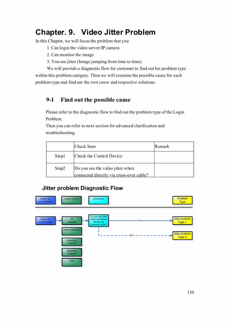
8/21/2019 IP Surveillance TroubleShooting Guide_V0.9
http://slidepdf.com/reader/full/ip-surveillance-troubleshooting-guidev09 161/347
159
Chapter. 9. Video Jitter ProblemIn this Chapter, we will focus the problem that you
1. Can login the video server/IP camera
2. Can monitor the image3. You see jitter (Image jumping from time to time)
We will provide a diagnostic flow for customer to find out his problem type
within this problem category. Then we will examine the possible cause for each
problem type and find out the root cause and respective solutions.
9-1 Find out the possible cause
Please refer to the diagnostic flow to find out the problem type of the LoginProblem.
Then you can refer to next section for advanced clarification and
troubleshooting.
Check Item Remark
Step1 Check the Control Device
Step2 Do you see the video jitter whenconnected directly via cross-over cable?

8/21/2019 IP Surveillance TroubleShooting Guide_V0.9
http://slidepdf.com/reader/full/ip-surveillance-troubleshooting-guidev09 162/347
160
9-2 Video Jitter problem Type 1
Refer to the cause clarification and respective solutions of each problem
type below. RED circled parts below indicating which building block mightcause this problem.
9-2-1 Monitor, Management, Storage Block
The possible causes could be as below.
9-2.1.1 Inappropriate PC specs
The jitter problem might happen if your PC doesn’t have enough
computing power to decode the image.
Clarification:
1. Check out the support package TS-00057 to check if your
PC meets the system requirement of our software.
Network
Management
Storage
maging
Monitor
Management
8/21/2019 IP Surveillance TroubleShooting Guide_V0.9
http://slidepdf.com/reader/full/ip-surveillance-troubleshooting-guidev09 163/347
161
2. If your system meets the requirement, this is not an
inappropriate PC spec problem.
3. If your system fails to meet to requirement, this is an
inappropriate PC spec problem.
Solution:
1. Please follow the system requirement in support package
TS-00057 to adjust your PC spec.
9-2.1.2 Inappropriate PC network card
The PC network card directly effect the network performance of
a. Speed
b. Stability
If the PC network card is bad, the jitter is likely to happen.
Clarification:
1. Check out the PC network card spec, and see if it is using
“Intel” chipsets.
2. If yes, this is NOT an inappropriate network card problem.
3. If not, this is an inappropriate network card problem.
Solution:
1. Please change the PC network card with Intel Chipset.
Note: Network cards with Intel Chipset have tested to bereliable and fast.
9-2-2 If problem not solved, how to report thisproblem?
If the solution above can’t solve the problem, please gather the following
information and contact our sales. (Please see introduction about how to
contact).
8/21/2019 IP Surveillance TroubleShooting Guide_V0.9
http://slidepdf.com/reader/full/ip-surveillance-troubleshooting-guidev09 164/347
162
9-2.2.1 Problem feedback table
Problem feedback table of login problem 1
Category Sub-category Description
Hard model Model number
Firmware Firmware version
Software model
Software
version
Network
connection
Connection
(LAN or WAN or
cross-over)CPU
RAM
Motherboard FSB
VGA card
PC spec
PC network card
Other details
you find during
clarification
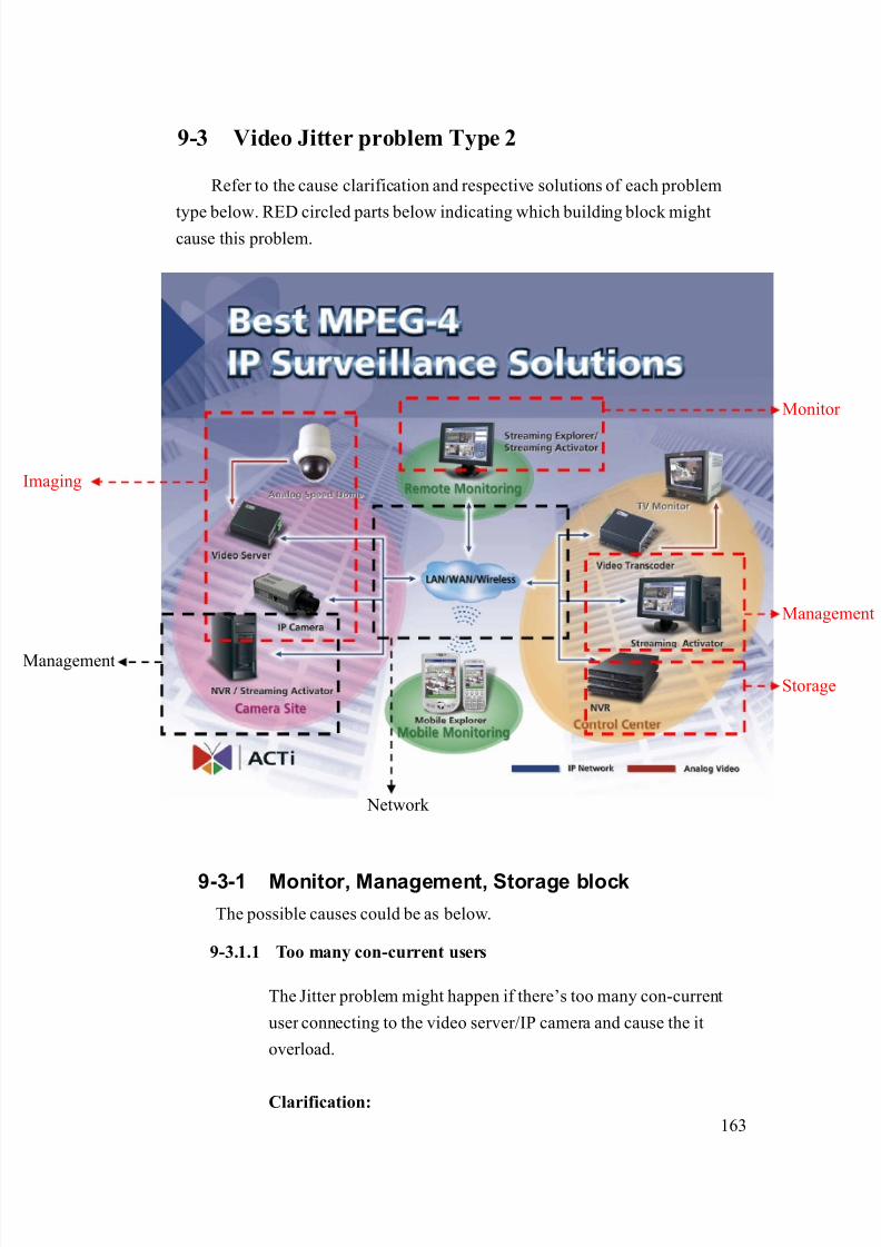
8/21/2019 IP Surveillance TroubleShooting Guide_V0.9
http://slidepdf.com/reader/full/ip-surveillance-troubleshooting-guidev09 165/347
163
9-3 Video Jitter problem Type 2
Refer to the cause clarification and respective solutions of each problem
type below. RED circled parts below indicating which building block mightcause this problem.
9-3-1 Monitor, Management, Storage block
The possible causes could be as below.
9-3.1.1 Too many con-current users
The Jitter problem might happen if there’s too many con-current
user connecting to the video server/IP camera and cause the it
overload.
Clarification:
Network
Management
Storage
maging
Monitor
Management
8/21/2019 IP Surveillance TroubleShooting Guide_V0.9
http://slidepdf.com/reader/full/ip-surveillance-troubleshooting-guidev09 166/347
164
1. Please fill in the table below about the video setting and
number of con-current users. (If you use one PC to record,
and one PC to view the images, there are two con-current
user of this video server/IP camera)
Item Description
Bit rate
Protocol Type
(TCP1.0 or TCP2.0)*
Number of
connections
* Please refer to the support package TS-00104 and your
video setting in web-configurator for Protocol type are
you using.
Example:
Item Description
Bit rate 3M
Protocol Type
(TCP1.0 or TCP2.0)
1
Number of
connections
2
2. Refer to the table below to find out the con-current user
we support. This table is divided by different combination
of bit rate and protocol types.
Protocol typeBit rate
TCP1.0 TCP2.0
3M 1 2
1.5M 3 6
750K 6 12
3. If your con-current user exceeds the con-current user we
supported, this is a problem of too many con-current users.
4. If your con-current user doesn’t exceed the con-current

8/21/2019 IP Surveillance TroubleShooting Guide_V0.9
http://slidepdf.com/reader/full/ip-surveillance-troubleshooting-guidev09 167/347
165
user we supported, this is a problem of too many
con-current users.
Solution:
1. There are two types of solution to solve this problem.
a. Decrease the bit rate to increase the con-current
user (Note: Decrease the bit rate might cause the
video quality to decrease as well)
b. Decrease the number of con-current user. (decrease
the number of user by changing system design)
9-3-2 Network blockThe possible causes could be as below.
9-3.2.1 Insufficient/instable network bandwidth
Insufficient network bandwidth or instable network bandwidth is
very likely to cause the network package to be lost during
transmission. Too many drop network packages will cause the jitter
to happen.
Clarification:
1. Because the jitter problem disappears when connecting via
cross-over cable. The problem definition will be as below
Connection Type Jitter Normal
Previous network ●
Cross-over ●
2. Please bring the test result to your MIS or the one build-upyour network infrastructure and ask him to clarify if the
network bandwidth is ok and stable.
Item Description
Bit rate 3M
Protocol Type
(TCP1.0 or TCP2.0)
1
Number of
connections
2
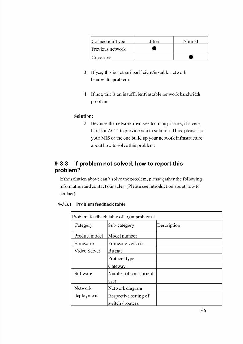
8/21/2019 IP Surveillance TroubleShooting Guide_V0.9
http://slidepdf.com/reader/full/ip-surveillance-troubleshooting-guidev09 168/347
166
Connection Type Jitter Normal
Previous network ●
Cross-over ●
3. If yes, this is not an insufficient/instable network
bandwidth problem.
4. If not, this is an insufficient/instable network bandwidth
problem.
Solution:
2. Because the network involves too many issues, it’s very
hard for ACTi to provide you to solution. Thus, please ask
your MIS or the one build up your network infrastructure
about how to solve this problem.
9-3-3 If problem not solved, how to report thisproblem?
If the solution above can’t solve the problem, please gather the followinginformation and contact our sales. (Please see introduction about how to
contact).
9-3.3.1 Problem feedback table
Problem feedback table of login problem 1
Category Sub-category Description
Product model Model number
Firmware Firmware version
Bit rate
Protocol type
Video Server
Gateway
Software Number of con-current
user
Network diagram Network
deployment Respective setting of
switch / routers.
8/21/2019 IP Surveillance TroubleShooting Guide_V0.9
http://slidepdf.com/reader/full/ip-surveillance-troubleshooting-guidev09 169/347
167
Chapter. 10. DIO event ProblemIn this Chapter, we will focus the problem that you
1. Can login the video server/IP camera
2. Can monitor the image3. You can’t use DI and DO function (Example: You can’t record every time
you receive DI or you can’t manually trigger DO.)
We will provide a diagnostic flow for customer to find out his problem type
within this problem category. Then we will examine the possible cause for each
problem type and find out the root cause and respective solutions.
10-1 Find out the possible cause
Please refer to the diagnostic flow to find out the problem type of the DI/OProblem. You can see a table right beside each problem type indicating which
building block of the IP surveillance might cause the problem.
Then you can refer to next section for advanced clarification and
troubleshooting.
Check Item Remark
Step1 Check the Control Device
Step2 What DI/DO function do you have
problem with?
Step3 Can Streaming Activator Receive DI
signal while connecting directly via
cross-over cable?
Operation procedure
will be added in
next version
Other advanced clarification related to each problem.
Can your PC use the same FTP setting to
send FTP?
Can your PC use the same e-mail setting
to send e-mail?
Step4
Can your PC send DO signal to the video
server / IP camera?
Operation procedure
will be added in
next version
8/21/2019 IP Surveillance TroubleShooting Guide_V0.9
http://slidepdf.com/reader/full/ip-surveillance-troubleshooting-guidev09 170/347
168
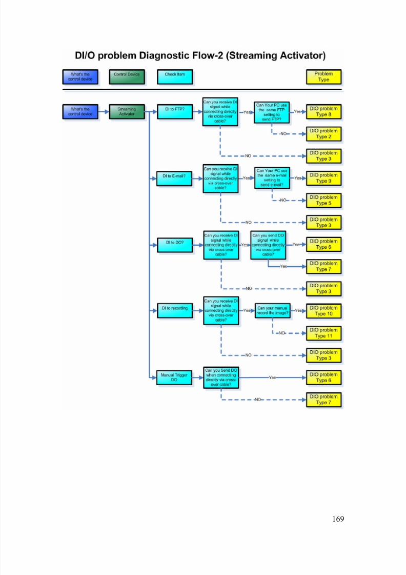
8/21/2019 IP Surveillance TroubleShooting Guide_V0.9
http://slidepdf.com/reader/full/ip-surveillance-troubleshooting-guidev09 171/347
169
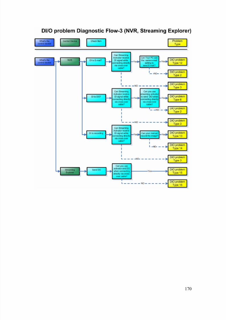
8/21/2019 IP Surveillance TroubleShooting Guide_V0.9
http://slidepdf.com/reader/full/ip-surveillance-troubleshooting-guidev09 172/347
170

8/21/2019 IP Surveillance TroubleShooting Guide_V0.9
http://slidepdf.com/reader/full/ip-surveillance-troubleshooting-guidev09 173/347
171
10-2 DIO problem Type 1
Refer to the cause clarification and respective solutions of each problem
type below. RED circled parts below indicating which building block mightcause this problem.
10-2-1 Image block
The possible causes could be as below.
10-2.1.1 Inappropriate network platform – FTP client setting
This problem could happen if you didn’t setup the FTP client
setting in the web-configurator right.
Clarification:
1. Please read the support package TS-00019 for how to
setup the FTP setting.
Network
Management
Storage
maging
Monitor
Management

8/21/2019 IP Surveillance TroubleShooting Guide_V0.9
http://slidepdf.com/reader/full/ip-surveillance-troubleshooting-guidev09 174/347
172
2. Clarify if your settings are right.
3. If yes, this is NOT a network platform – FTP client setting
4. If not, this is a network platform – FTP client setting.
Solution:
1. Please refer to the support package TS-00019 for how to
correctly set it.
10-2.1.2 Inappropriate network platform – event setting
This problem could happen if you didn’t setup the event setting in
the web-configurator right.
Clarification:
1. Please read the support package TS-00019 for how to
setup the event setting.
2. Clarify if your settings are right.
3. If yes, this is NOT a network platform – event setting
4. If not, this is a network platform –event setting.
Solution:1. Please refer to the support package TS-00019 for how to
correctly set it.
10-2-2 If problem not solved, how to report thisproblem?
If the solution above can’t solve the problem, please gather the following
information and contact our sales. (Please see introduction about how to
contact).
10-2.2.1 Problem feedback table
Problem feedback table of login problem 1
Category Sub-category Description
Product model Model number
Firmware Firmware version
Video Server Use it to connect?

8/21/2019 IP Surveillance TroubleShooting Guide_V0.9
http://slidepdf.com/reader/full/ip-surveillance-troubleshooting-guidev09 175/347
173
IP address
Submask
LAN IP setting
Gateway
Use it to connect?
IP address
Submask
Video Server
WAN IP setting
Gateway
FTP settingVideo server
event setting Event action
Network diagram Network
deployment Respective setting of
switch / routers.
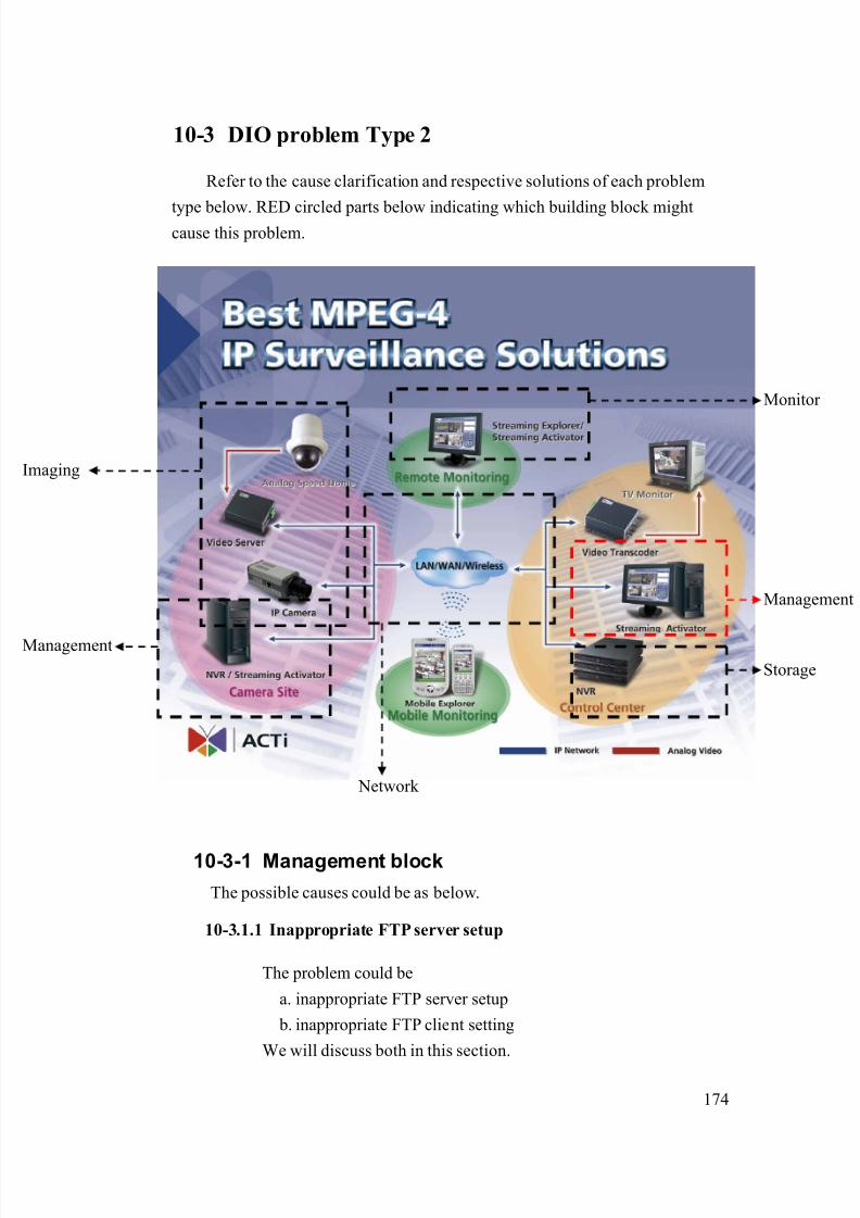
8/21/2019 IP Surveillance TroubleShooting Guide_V0.9
http://slidepdf.com/reader/full/ip-surveillance-troubleshooting-guidev09 176/347
174
10-3 DIO problem Type 2
Refer to the cause clarification and respective solutions of each problem
type below. RED circled parts below indicating which building block mightcause this problem.
10-3-1 Management block
The possible causes could be as below.
10-3.1.1 Inappropriate FTP server setup
The problem could be
a. inappropriate FTP server setup
b. inappropriate FTP client setting
We will discuss both in this section.
Network
Management
Storage
maging
Monitor
Management
8/21/2019 IP Surveillance TroubleShooting Guide_V0.9
http://slidepdf.com/reader/full/ip-surveillance-troubleshooting-guidev09 177/347
175
Clarification:
1. Because you fail to connect the FTP setting using your
own PC, that means there’s something wrong about the
a. FTP server setup and
b. FTP client setting.
2. Because this problem involves mostly about your network
and MIS infrastructure, it’s less possible for us to provide
the solution.
Solution:
1. Please provide the following item and give it to your MIS
or your network architect for this problem. Ask him for
solution.
Category Sub-category Settings
Server PCFTP server
Other
Server IP
Account
Password
File Path
FTP Client
Other
10-3.1.2 Inappropriate FTP client setting (account and password)
The problem is discussed in 10-3.1.1, please go there for details
10-3-2 If problem not solved, how to report this
problem?
If the solution above can’t solve the problem, please gather the following
information and contact our sales. (Please see introduction about how to
contact).
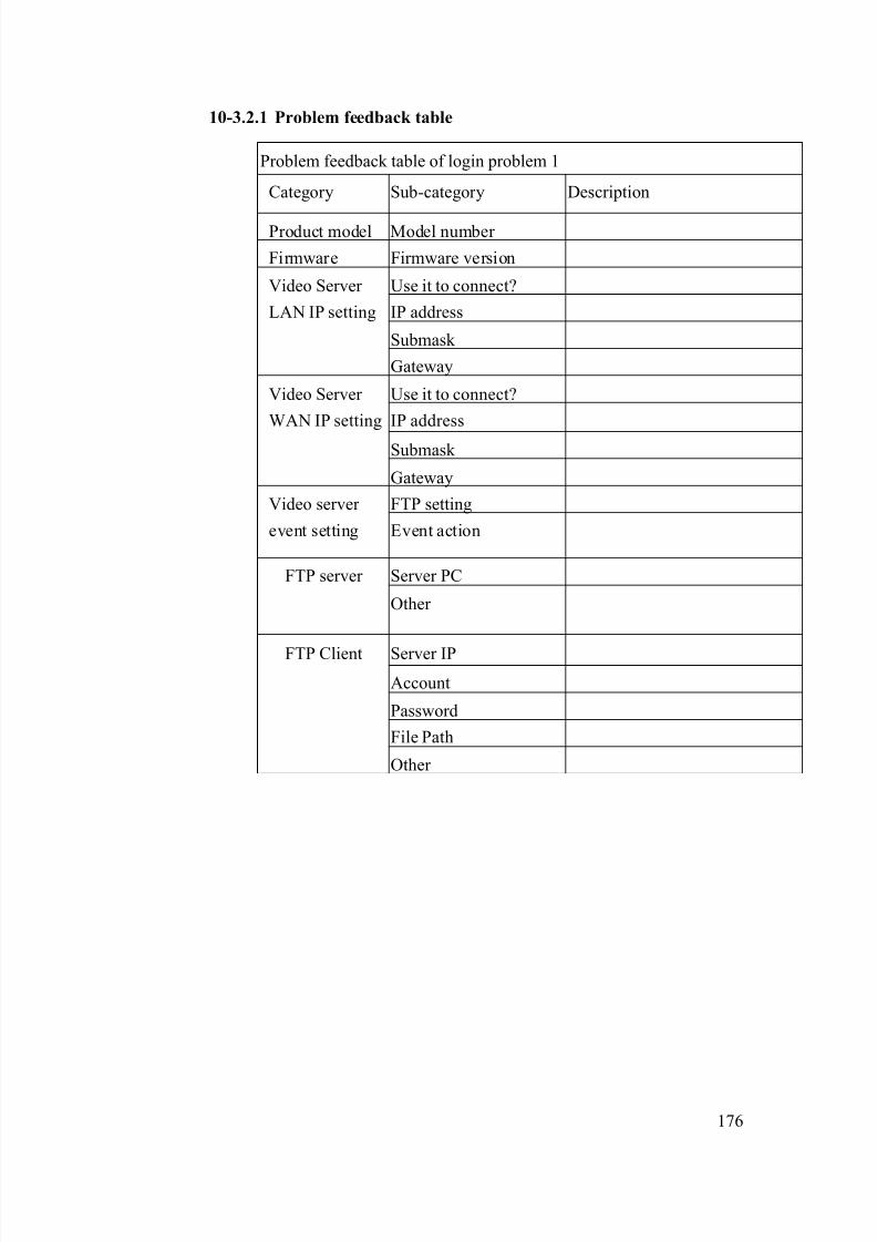
8/21/2019 IP Surveillance TroubleShooting Guide_V0.9
http://slidepdf.com/reader/full/ip-surveillance-troubleshooting-guidev09 178/347
176
10-3.2.1 Problem feedback table
Problem feedback table of login problem 1
Category Sub-category Description
Product model Model number
Firmware Firmware version
Use it to connect?
IP address
Submask
Video Server
LAN IP setting
Gateway
Use it to connect?
IP address
Submask
Video Server
WAN IP setting
Gateway
FTP settingVideo server
event setting Event action
Server PCFTP server
Other
Server IP
Account
Password
File Path
FTP Client
Other

8/21/2019 IP Surveillance TroubleShooting Guide_V0.9
http://slidepdf.com/reader/full/ip-surveillance-troubleshooting-guidev09 179/347
177
10-4 DIO problem Type 3
Refer to the cause clarification and respective solutions of each problem
type below. RED circled parts below indicating which building block mightcause this problem.
10-4-1 Image block
The possible causes could be as below.
10-4.1.1 Inappropriate DI devices
The problem can be resulted by
a. Inappropriate DI devices or
b. Inappropriate DI connections
Network
Management
Storage
maging
Monitor
Management

8/21/2019 IP Surveillance TroubleShooting Guide_V0.9
http://slidepdf.com/reader/full/ip-surveillance-troubleshooting-guidev09 180/347
178
Clarification:
1. Please read the support package TS-00045 to clarify if
your DI device spec is right.
2. Please read the support package TS-00045 to clarify if
your DI connection is right.
3. If yes, this is NOT a DI device or DI connection problem.
4. If not, this is a DI device or DI connection problem
Solution:
1. Please refer to the support package TS-00045 for how to
correctly set it.
10-4.1.2 Inappropriate DI connections
The problem is discussed in 10-4.1.1, please go there for details.
10-4-2 If problem not solved, how to report thisproblem?
If the solution above can’t solve the problem, please gather the following
information and contact our sales. (Please see introduction about how to
contact).
10-4.2.1 Problem feedback table
Problem feedback table of login problem 1
Category Sub-category Description
Product model Model number
Firmware Firmware version
Software model
Software
version
DI device specDI
DI connection diagram
Other data you
find during
clarification
Server PC
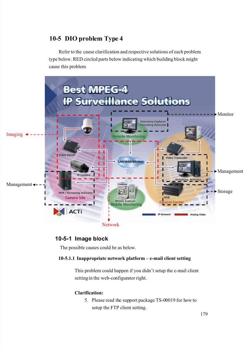
8/21/2019 IP Surveillance TroubleShooting Guide_V0.9
http://slidepdf.com/reader/full/ip-surveillance-troubleshooting-guidev09 181/347
179
10-5 DIO problem Type 4
Refer to the cause clarification and respective solutions of each problem
type below. RED circled parts below indicating which building block mightcause this problem.
10-5-1 Image block
The possible causes could be as below.
10-5.1.1 Inappropriate network platform – e-mail client setting
This problem could happen if you didn’t setup the e-mail client
setting in the web-configurator right.
Clarification:
5. Please read the support package TS-00019 for how to
setup the FTP client setting.
Network
Management
Storage
maging
Monitor
Management

8/21/2019 IP Surveillance TroubleShooting Guide_V0.9
http://slidepdf.com/reader/full/ip-surveillance-troubleshooting-guidev09 182/347
180
6. Clarify if your settings are right.
7. If yes, this is NOT a network platform – e-mail client
setting
8. If not, this is a network platform – e-mail client setting.
Solution:
2. Please refer to the support package TS-00019 for how to
correctly set it.
10-5.1.2 Inappropriate network platform – event setting
This problem could happen if you didn’t setup the event setting in
the web-configurator right.
Clarification:
5. Please read the support package TS-00019 for how to
setup the event setting.
6. Clarify if your settings are right.
7. If yes, this is NOT a network platform – event setting
8. If not, this is a network platform –event setting.
Solution:
2. Please refer to the support package TS-00019 for how to
correctly set it.
10-5-2 If problem not solved, how to report thisproblem?
If the solution above can’t solve the problem, please gather the following
information and contact our sales. (Please see introduction about how to
contact).
10-5.2.1 Problem feedback table
Problem feedback table of login problem 1
Category Sub-category Description
Product model Model number
Firmware Firmware version

8/21/2019 IP Surveillance TroubleShooting Guide_V0.9
http://slidepdf.com/reader/full/ip-surveillance-troubleshooting-guidev09 183/347
181
Use it to connect?
IP address
Submask
Video Server
LAN IP setting
Gateway
Use it to connect?
IP address
Submask
Video Server
WAN IP setting
Gateway
E-mail Client settingVideo server
event setting Event action
Network diagram Network
deployment Respective setting of
switch / routers.

8/21/2019 IP Surveillance TroubleShooting Guide_V0.9
http://slidepdf.com/reader/full/ip-surveillance-troubleshooting-guidev09 184/347
182
10-6 DIO problem Type 5
Refer to the cause clarification and respective solutions of each problem
type below. RED circled parts below indicating which building block mightcause this problem.
10-6-1 Management block
The possible causes could be as below.
10-6.1.1 Inappropriate e-mail server setup
The problem could be
a. inappropriate e-mail server setup
b. inappropriate e-mail client setting
We will discuss both in this section.
Network
Management
Storage
maging
Monitor
Management

8/21/2019 IP Surveillance TroubleShooting Guide_V0.9
http://slidepdf.com/reader/full/ip-surveillance-troubleshooting-guidev09 185/347
183
Clarification:
1. Because you fail to connect the e-mail setting using your
own PC, that means there’s something wrong about the
a. e-mail server setup and
b. e-mail client setting.
2. Because this problem involves mostly about your network
and MIS infrastructure, it’s less possible for us to provide
the solution.
Solution:
1. Please provide the following item and give it to your MIS
or your network architect for this problem. Ask him for
solution.
Category Sub-category Settings
Server PCe-mail server
Other
Server IP
Account
Password
File Path
e-mail Client
Other
10-6.1.2 Inappropriate FTP client setting (account and password)
The problem is discussed in 10-6.1.1, please go there for details
10-6-2 If problem not solved, how to report this
problem?
If the solution above can’t solve the problem, please gather the following
information and contact our sales. (Please see introduction about how to
contact).

8/21/2019 IP Surveillance TroubleShooting Guide_V0.9
http://slidepdf.com/reader/full/ip-surveillance-troubleshooting-guidev09 186/347
184
10-6.2.1 Problem feedback table
Problem feedback table of login problem 1
Category Sub-category Description
Product model Model number
Firmware Firmware version
Use it to connect?
IP address
Submask
Video Server
LAN IP setting
Gateway
Use it to connect?
IP address
Submask
Video Server
WAN IP setting
Gateway
FTP settingVideo server
event setting Event action
Server PCe-mail server
Other
Server IP
Account
Password
File Path
e-mail Client
Other

8/21/2019 IP Surveillance TroubleShooting Guide_V0.9
http://slidepdf.com/reader/full/ip-surveillance-troubleshooting-guidev09 187/347
185
10-7 DIO problem Type 6
Refer to the cause clarification and respective solutions of each problem
type below. RED circled parts below indicating which building block mightcause this problem.
10-7-1 Image block
The possible causes could be as below.
10-7.1.1 Inappropriate network platform – event setting
This problem could happen if you didn’t setup the event setting in
the web-configurator right.
Clarification:
1. Please read the support package TS-00019 for how to
Network
Management
Storage
maging
Monitor
Management
8/21/2019 IP Surveillance TroubleShooting Guide_V0.9
http://slidepdf.com/reader/full/ip-surveillance-troubleshooting-guidev09 188/347
186
setup the event setting.
2. Clarify if your settings are right.
3. If yes, this is NOT a network platform – event setting
4. If not, this is a network platform –event setting.
Solution:
1. Please refer to the support package TS-00019 for how to
correctly set it.
10-7-2 If problem not solved, how to report this
problem?
If the solution above can’t solve the problem, please gather the followinginformation and contact our sales. (Please see introduction about how to
contact).
10-7.2.1 Problem feedback table
Problem feedback table of login problem 1
Category Sub-category Description
Product model Model number
Firmware Firmware version
Use it to connect?
IP address
Submask
Video Server
LAN IP setting
Gateway
Use it to connect?
IP address
Submask
Video Server
WAN IP setting
Gateway
Video server
event setting
Event action
Network diagram Network
deployment Respective setting of
switch / routers.
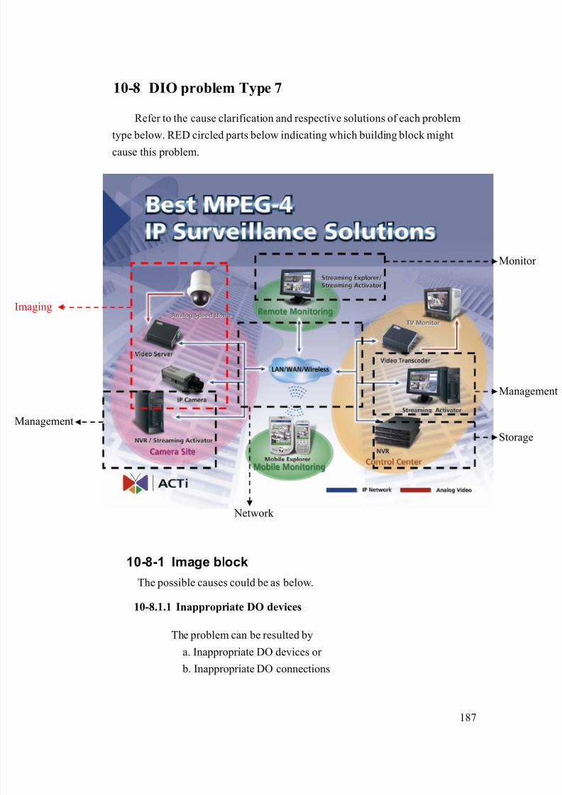
8/21/2019 IP Surveillance TroubleShooting Guide_V0.9
http://slidepdf.com/reader/full/ip-surveillance-troubleshooting-guidev09 189/347
187
10-8 DIO problem Type 7
Refer to the cause clarification and respective solutions of each problem
type below. RED circled parts below indicating which building block mightcause this problem.
10-8-1 Image block
The possible causes could be as below.
10-8.1.1 Inappropriate DO devices
The problem can be resulted by
a. Inappropriate DO devices or
b. Inappropriate DO connections
Network
Management
Storage
maging
Monitor
Management
8/21/2019 IP Surveillance TroubleShooting Guide_V0.9
http://slidepdf.com/reader/full/ip-surveillance-troubleshooting-guidev09 190/347
188
Clarification:
1. Please read the support package TS-00045 to clarify if
your DO device spec is right.
2. Please read the support package TS-00045 to clarify if
your DI connection is right.
3. If yes, this is NOT a DO device or DO connection
problem.
4. If not, this is a DO device or DO connection problem
Solution:
1. Please refer to the support package TS-00045 for how to
correctly set it.
10-8.1.2 Inappropriate DO connections
The problem is discussed in 10-8.1.1, please go there for details.
10-8-2 If problem not solved, how to report thisproblem?
If the solution above can’t solve the problem, please gather the following
information and contact our sales. (Please see introduction about how to
contact).
10-8.2.1 Problem feedback table
Problem feedback table of login problem 1
Category Sub-category Description
Product model Model number
Firmware Firmware version
Software model
Software
version
DO device specDO
DO connection diagram
Other data you
find during
Server PC

8/21/2019 IP Surveillance TroubleShooting Guide_V0.9
http://slidepdf.com/reader/full/ip-surveillance-troubleshooting-guidev09 191/347
189
clarification

8/21/2019 IP Surveillance TroubleShooting Guide_V0.9
http://slidepdf.com/reader/full/ip-surveillance-troubleshooting-guidev09 192/347
190
10-9 DIO problem Type 8
Refer to the cause clarification and respective solutions of each problem
type below. RED circled parts below indicating which building block mightcause this problem.
10-9-1 Network block
The possible causes could be as below.
10-9.1.1 Inappropriate network infrastructure (if you were connecting
via LAN)
The problem could be the inappropriate network infrastructure.
Clarification:
1. Below is the status of this problem definition so far.
Network
Management
Storage
maging
Monitor
Management

8/21/2019 IP Surveillance TroubleShooting Guide_V0.9
http://slidepdf.com/reader/full/ip-surveillance-troubleshooting-guidev09 193/347
191
Network
environment Respective network ports
Function
Cross-over LAN Port name Port number (Default)
Login Yes Yes HTTP 80
HTTP 80
Register 6000
View image Yes Yes
Streaming 6002
DIO signal Yes No Control 6001
2. As you can see from the table, there’s something wrong
about your LAN.
Solution:
1. Because this problem involves mostly about your LAN
environment, it’s less possible for us to provide the
solution.
2. Please fill in your definition table
Network environment Respective network ports
Function
Cross-over LAN Port name Port number
Login Yes Yes HTTP
HTTP
Register
View image Yes Yes
Streaming
DIO signal Yes No Control
3. Please provide the definition table above to your MIS or
your network architect for this problem. Ask him for
solution.
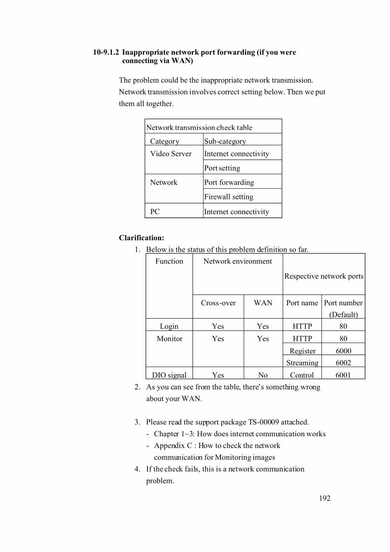
8/21/2019 IP Surveillance TroubleShooting Guide_V0.9
http://slidepdf.com/reader/full/ip-surveillance-troubleshooting-guidev09 194/347
192
10-9.1.2 Inappropriate network port forwarding (if you wereconnecting via WAN)
The problem could be the inappropriate network transmission.
Network transmission involves correct setting below. Then we put
them all together.
Network transmission check table
Category Sub-category
Internet connectivityVideo Server
Port setting
Port forwarding Network
Firewall setting
PC Internet connectivity
Clarification:
1. Below is the status of this problem definition so far.
Network environment
Respective network ports
Function
Cross-over WAN Port name Port number
(Default)
Login Yes Yes HTTP 80
HTTP 80
Register 6000
Monitor Yes Yes
Streaming 6002
DIO signal Yes No Control 6001
2. As you can see from the table, there’s something wrongabout your WAN.
3. Please read the support package TS-00009 attached.
- Chapter 1~3: How does internet communication works
- Appendix C : How to check the network
communication for Monitoring images
4. If the check fails, this is a network communication
problem.

8/21/2019 IP Surveillance TroubleShooting Guide_V0.9
http://slidepdf.com/reader/full/ip-surveillance-troubleshooting-guidev09 195/347
193
5. If the check ok, this is not a network communication
problem.
Solution:
1. Follows the support package TS-00009 to build up the
internet communication step by step. .
10-9.1.3 Blocked by firewall (if you were connecting via WAN)
The problem is discussed in 10-9.1.2, please go there for details.
10-9.1.4 DNS problem (if you were connecting via DNS)
This problem could happen if you connect to the video server/IP
camera using Domain Name (Ex: http://myroom.dyndns.org)
instead of IP address (Ex: http://59.233.23.59).
Clarification:
1. Please switch the software setting from IP address from
Domain Name to IP address and see if you can monitor
the images.
2. If yes, this is a DNS problem.
3. If not, this is not a DNS problem.
Solution:
1. Report the following information to our sales. We will
provide you an updated version A.S.A.P.
Category Description Example:
HardwareModel number
SED-2120
Firmware
version
A1D-V2.00.00
Software model NVR
Software
version
V1.00.00
2. Before you get that updated version, you can use IP
8/21/2019 IP Surveillance TroubleShooting Guide_V0.9
http://slidepdf.com/reader/full/ip-surveillance-troubleshooting-guidev09 196/347
194
address instead of Domain name to connect to the video
server/IP camera a contingency plan.
10-9-2 Management block
The possible causes could be as below.
10-9.2.1 Inappropriate Streaming Activator – FTP client setting
This problem could happen if you didn’t setup the FTP client
setting in the Streaming Activator right.
Clarification:1. Please read the Streaming Activator’s software manual for
how to setup the FTP client setting.
2. Clarify if your settings are right.
3. If yes, this is NOT an inappropriate Streaming Activator –
FTP setting
4. If not, this is an inappropriate Streaming Activator – FTP
client setting.
Solution:
1. Please refer to the Streaming Activator’s software manual
for how to correctly set it.
10-9.2.2 Inappropriate Streaming Activator – event setting
This problem could happen if you didn’t setup the event setting in
the Streaming Activator right.
Clarification:
1. Please read the Streaming Activator’s software manual for
how to setup the event setting.
2. Clarify if your settings are right.
3. If yes, this is NOT an inappropriate Streaming Activator –
event setting
4. If not, this is an inappropriate Streaming Activator – event
client setting.
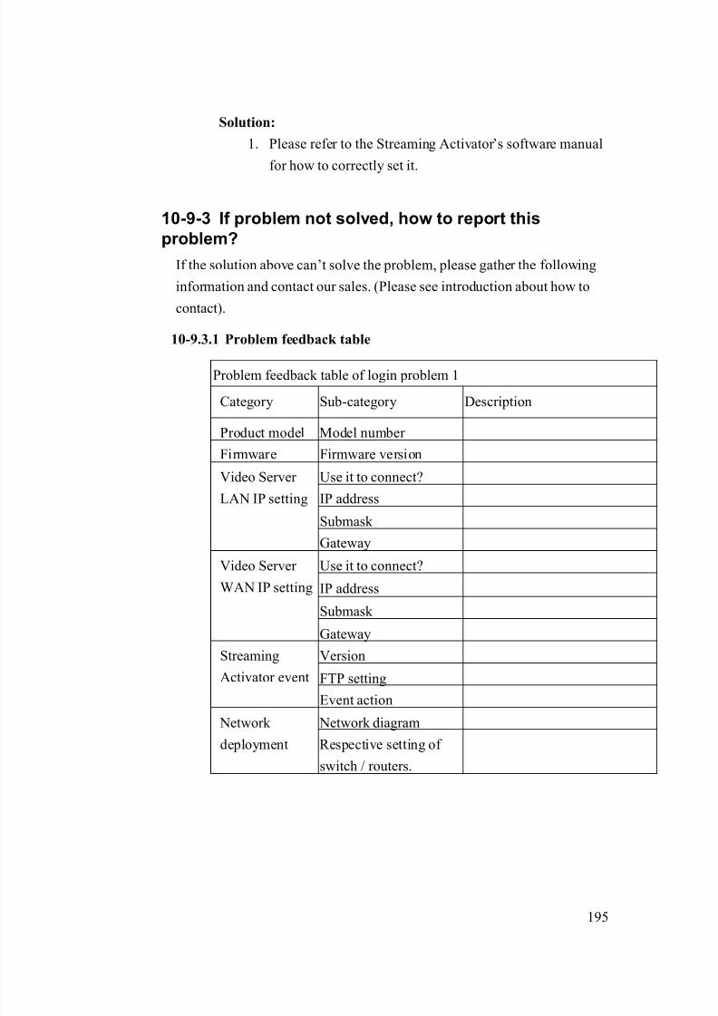
8/21/2019 IP Surveillance TroubleShooting Guide_V0.9
http://slidepdf.com/reader/full/ip-surveillance-troubleshooting-guidev09 197/347
195
Solution:
1. Please refer to the Streaming Activator’s software manual
for how to correctly set it.
10-9-3 If problem not solved, how to report this
problem?
If the solution above can’t solve the problem, please gather the following
information and contact our sales. (Please see introduction about how to
contact).
10-9.3.1 Problem feedback table
Problem feedback table of login problem 1
Category Sub-category Description
Product model Model number
Firmware Firmware version
Use it to connect?
IP address
Submask
Video Server
LAN IP setting
Gateway
Use it to connect?
IP address
Submask
Video Server
WAN IP setting
Gateway
Version
FTP setting
Streaming
Activator event
Event action
Network diagram Network
deployment Respective setting of
switch / routers.

8/21/2019 IP Surveillance TroubleShooting Guide_V0.9
http://slidepdf.com/reader/full/ip-surveillance-troubleshooting-guidev09 198/347
196
10-10 DIO problem Type 9
Refer to the cause clarification and respective solutions of each problem
type below. RED circled parts below indicating which building block mightcause this problem.
10-10-1 Network block
The possible causes could be as below.
10-10.1.1 Inappropriate network infrastructure (if you were
connecting via LAN)
The problem could be the inappropriate network infrastructure.
Clarification:
1. Below is the status of this problem definition so far.
Network
Management
Storage
maging
Monitor
Management

8/21/2019 IP Surveillance TroubleShooting Guide_V0.9
http://slidepdf.com/reader/full/ip-surveillance-troubleshooting-guidev09 199/347
197
Network
environment Respective network ports
Function
Cross-over LAN Port name Port number (Default)
Login Yes Yes HTTP 80
HTTP 80
Register 6000
View image Yes Yes
Streaming 6002
DIO signal Yes No Control 6001
2. As you can see from the table, there’s something wrong
about your LAN.
Solution:
1. Because this problem involves mostly about your LAN
environment, it’s less possible for us to provide the
solution.
2. Please fill in your definition table
Network environment Respective network ports
Function
Cross-over LAN Port name Port number
Login Yes Yes HTTP
HTTP
Register
View image Yes Yes
Streaming
DIO signal Yes No Control
3. Please provide the definition table above to your MIS or
your network architect for this problem. Ask him for
solution.

8/21/2019 IP Surveillance TroubleShooting Guide_V0.9
http://slidepdf.com/reader/full/ip-surveillance-troubleshooting-guidev09 200/347
198
10-10.1.2 Inappropriate network port forwarding (if you wereconnecting via WAN)
The problem could be the inappropriate network transmission.
Network transmission involves correct setting below. Then we put
them all together.
Network transmission check table
Category Sub-category
Internet connectivityVideo Server
Port setting
Port forwarding Network
Firewall setting
PC Internet connectivity
Clarification:
1. Below is the status of this problem definition so far.
Network environment
Respective network ports
Function
Cross-over WAN Port name Port number
(Default)
Login Yes Yes HTTP 80
HTTP 80
Register 6000
Monitor Yes Yes
Streaming 6002
DIO signal Yes No Control 6001
2. As you can see from the table, there’s something wrongabout your WAN.
3. Please read the support package TS-00009 attached.
- Chapter 1~3: How does internet communication works
- Appendix C : How to check the network
communication for Monitoring images
4. If the check fails, this is a network communication
problem.

8/21/2019 IP Surveillance TroubleShooting Guide_V0.9
http://slidepdf.com/reader/full/ip-surveillance-troubleshooting-guidev09 201/347
199
5. If the check ok, this is not a network communication
problem.
Solution:
1. Follows the support package TS-00009 to build up the
internet communication step by step. .
10-10.1.3 Blocked by firewall (if you were connecting via WAN)
The problem is discussed in 10-10.1.2, please go there for details.
10-10.1.4 DNS problem (if you were connecting via DNS)
This problem could happen if you connect to the video server/IP
camera using Domain Name (Ex: http://myroom.dyndns.org)
instead of IP address (Ex: http://59.233.23.59).
Clarification:
1. Please switch the software setting from IP address from
Domain Name to IP address and see if you can monitor
the images.
2. If yes, this is a DNS problem.
3. If not, this is not a DNS problem.
Solution:
1. Report the following information to our sales. We will
provide you an updated version A.S.A.P.
Category Description Example:
HardwareModel number
SED-2120
Firmware
version
A1D-V2.00.00
Software model NVR
Software
version
V1.00.00
2. Before you get that updated version, you can use IP
8/21/2019 IP Surveillance TroubleShooting Guide_V0.9
http://slidepdf.com/reader/full/ip-surveillance-troubleshooting-guidev09 202/347
200
address instead of Domain name to connect to the video
server/IP camera a contingency plan.
10-10-2 Management block
The possible causes could be as below.
10-10.2.1 Inappropriate Streaming Activator – e-mail client setting
This problem could happen if you didn’t setup the e-mail client
setting in the Streaming Activator right.
Clarification:1. Please read the Streaming Activator’s software manual for
how to setup the e-mail client setting.
2. Clarify if your settings are right.
3. If yes, this is NOT an inappropriate Streaming
Activator –e-mail client setting
4. If not, this is an inappropriate Streaming Activator –
e-mail client setting.
Solution:
1. Please refer to the Streaming Activator’s software manual
for how to correctly set it.
10-10.2.2 Inappropriate Streaming Activator – event setting
This problem could happen if you didn’t setup the event setting in
the Streaming Activator right.
Clarification:
1. Please read the Streaming Activator’s software manual for
how to setup the event setting.
2. Clarify if your settings are right.
3. If yes, this is NOT an inappropriate Streaming Activator –
event setting
4. If not, this is an inappropriate Streaming Activator – event
client setting.

8/21/2019 IP Surveillance TroubleShooting Guide_V0.9
http://slidepdf.com/reader/full/ip-surveillance-troubleshooting-guidev09 203/347
201
Solution:
1. Please refer to the Streaming Activator’s software manual
for how to correctly set it.
10-10-3 If problem not solved, how to report this
problem?
If the solution above can’t solve the problem, please gather the following
information and contact our sales. (Please see introduction about how to
contact).
10-10.3.1 Problem feedback table
Problem feedback table of login problem 1
Category Sub-category Description
Product model Model number
Firmware Firmware version
Use it to connect?
IP address
Submask
Video Server
LAN IP setting
Gateway
Use it to connect?
IP address
Submask
Video Server
WAN IP setting
Gateway
Version
E-mail setting
Streaming
Activator event
Event action
Network diagram Network
deployment Respective setting of
switch / routers.

8/21/2019 IP Surveillance TroubleShooting Guide_V0.9
http://slidepdf.com/reader/full/ip-surveillance-troubleshooting-guidev09 204/347

8/21/2019 IP Surveillance TroubleShooting Guide_V0.9
http://slidepdf.com/reader/full/ip-surveillance-troubleshooting-guidev09 205/347
203
Network
environment Respective network ports
Function
Cross-over LAN Port name Port number (Default)
Login Yes Yes HTTP 80
HTTP 80
Register 6000
View image Yes Yes
Streaming 6002
DIO signal Yes No Control 6001
2. As you can see from the table, there’s something wrong
about your LAN.
Solution:
1. Because this problem involves mostly about your LAN
environment, it’s less possible for us to provide the
solution.
2. Please fill in your definition table
Network environment Respective network ports
Function
Cross-over LAN Port name Port number
Login Yes Yes HTTP
HTTP
Register
View image Yes Yes
Streaming
DIO signal Yes No Control
3. Please provide the definition table above to your MIS or
your network architect for this problem. Ask him for
solution.

8/21/2019 IP Surveillance TroubleShooting Guide_V0.9
http://slidepdf.com/reader/full/ip-surveillance-troubleshooting-guidev09 206/347
204
10-11.1.2 Inappropriate network port forwarding (if you wereconnecting via WAN)
The problem could be the inappropriate network transmission.
Network transmission involves correct setting below. Then we put
them all together.
Network transmission check table
Category Sub-category
Internet connectivityVideo Server
Port setting
Port forwarding Network
Firewall setting
PC Internet connectivity
Clarification:
1. Below is the status of this problem definition so far.
Network environment
Respective network ports
Function
Cross-over WAN Port name Port number
(Default)
Login Yes Yes HTTP 80
HTTP 80
Register 6000
Monitor Yes Yes
Streaming 6002
DIO signal Yes No Control 6001
2. As you can see from the table, there’s something wrongabout your WAN.
3. Please read the support package TS-00009 attached.
- Chapter 1~3: How does internet communication works
- Appendix C : How to check the network
communication for Monitoring images
4. If the check fails, this is a network communication
problem.

8/21/2019 IP Surveillance TroubleShooting Guide_V0.9
http://slidepdf.com/reader/full/ip-surveillance-troubleshooting-guidev09 207/347
205
5. If the check ok, this is not a network communication
problem.
Solution:
1. Follows the support package TS-00009 to build up the
internet communication step by step. .
10-11.1.3 Blocked by firewall (if you were connecting via WAN)
The problem is discussed in 10-11.1.2, please go there for details.
10-11.1.4 DNS problem (if you were connecting via DNS)
This problem could happen if you connect to the video server/IP
camera using Domain Name (Ex: http://myroom.dyndns.org)
instead of IP address (Ex: http://59.233.23.59).
Clarification:
1. Please switch the software setting from IP address from
Domain Name to IP address and see if you can monitor
the images.
2. If yes, this is a DNS problem.
3. If not, this is not a DNS problem.
Solution:
1. Report the following information to our sales. We will
provide you an updated version A.S.A.P.
Category Description Example:
HardwareModel number
SED-2120
Firmware
version
A1D-V2.00.00
Software model NVR
Software
version
V1.00.00
2. Before you get that updated version, you can use IP
8/21/2019 IP Surveillance TroubleShooting Guide_V0.9
http://slidepdf.com/reader/full/ip-surveillance-troubleshooting-guidev09 208/347
206
address instead of Domain name to connect to the video
server/IP camera a contingency plan.
10-11-2 Management block
The possible causes could be as below.
10-11.2.1 Inappropriate Streaming Activator – event setting
This problem could happen if you didn’t setup the event setting in
the Streaming Activator right.
Clarification:1. Please read the Streaming Activator’s software manual for
how to setup the event setting.
2. Clarify if your settings are right.
3. If yes, this is NOT an inappropriate Streaming Activator –
event setting
4. If not, this is an inappropriate Streaming Activator – event
client setting.
Solution:
1. Please refer to the Streaming Activator’s software manual
for how to correctly set it.
10-11-3 If problem not solved, how to report thisproblem?
If the solution above can’t solve the problem, please gather the following
information and contact our sales. (Please see introduction about how to
contact).
10-11.3.1 Problem feedback table
Problem feedback table of login problem 1
Category Sub-category Description
Product model Model number
Firmware Firmware version

8/21/2019 IP Surveillance TroubleShooting Guide_V0.9
http://slidepdf.com/reader/full/ip-surveillance-troubleshooting-guidev09 209/347
207
Use it to connect?
IP address
Submask
Video Server
LAN IP setting
Gateway
Use it to connect?
IP address
Submask
Video Server
WAN IP setting
Gateway
VersionStreaming
Activator event Event action
Network diagram Network
deployment Respective setting of
switch / routers.

8/21/2019 IP Surveillance TroubleShooting Guide_V0.9
http://slidepdf.com/reader/full/ip-surveillance-troubleshooting-guidev09 210/347
208
10-12 DIO problem Type 11
Refer to the cause clarification and respective solutions of each problem
type below. RED circled parts below indicating which building block mightcause this problem.
10-12-1 Management block
The possible causes could be as below.
10-12.1.1 Inappropriate recording setting
This problem could happen if your recording settings are wrong.
Clarification:
1. Please read the Streaming Activator’s software manual for
how to setup the record setting.
2. Clarify if your settings are right.
3. If yes, this is NOT an inappropriate recording – setting.
Network
Management
Storage
maging
Monitor
Management
8/21/2019 IP Surveillance TroubleShooting Guide_V0.9
http://slidepdf.com/reader/full/ip-surveillance-troubleshooting-guidev09 211/347
209
4. If not, this is an inappropriate recording – setting.
Solution:
1. Please refer to the Streaming Activator’s software
manual for how to correctly set it.
10-12.1.2 Inappropriate PC authority
This problem could happen if your have limited PC authority
which will cause you problem when
a. Executing program
b. Save recordings
Clarification:
1. Please check if you login this PC as “Administrator” or
any account with the same authority.
2. If yes, this is NOT an inappropriate PC authority.
3. If not, this is an inappropriate PC authority.
Solution:
1. Always login this PC as “Administrator”.
10-12.1.3 Insufficient HD space
If your HD space is not sufficient, you will have problem recording
files.
Clarification:
1. Open Streaming Activator 2. See if there’s HD insufficient warning pop-out right after
you login
3. If not, this is NOT an insufficient HD space.
4. If not, this is an insufficient HD space.
Solution:
1. Your system must have enough HD space for software to
record all the time.

8/21/2019 IP Surveillance TroubleShooting Guide_V0.9
http://slidepdf.com/reader/full/ip-surveillance-troubleshooting-guidev09 212/347
210
2. Please refer to each software’s manual for the space
required.
10-12-2 If problem not solved, how to report thisproblem?
If the solution above can’t solve the problem, please gather the following
information and contact our sales. (Please see introduction about how to
contact).
10-12.2.1 Problem feedback table
Problem feedback table of login problem 1
Category Sub-category Description
Product model Model number
Firmware Firmware version
Version
Recording setting
Software
HD space
PC login Authority
(As Admin, power user,or user)

8/21/2019 IP Surveillance TroubleShooting Guide_V0.9
http://slidepdf.com/reader/full/ip-surveillance-troubleshooting-guidev09 213/347
211
10-13 DIO problem Type 12
Refer to the cause clarification and respective solutions of each problem
type below. RED circled parts below indicating which building block mightcause this problem.
10-13-1 Network block
The possible causes could be as below.
10-13.1.1 Inappropriate network infrastructure (if you were
connecting via LAN)
The problem could be the inappropriate network infrastructure.
Clarification:
Network
Management
Storage
maging
Monitor
Management
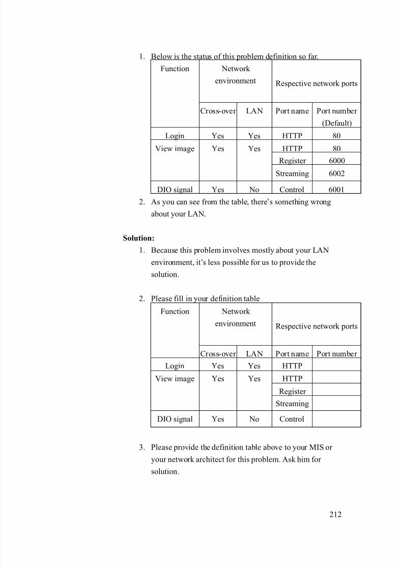
8/21/2019 IP Surveillance TroubleShooting Guide_V0.9
http://slidepdf.com/reader/full/ip-surveillance-troubleshooting-guidev09 214/347
212
1. Below is the status of this problem definition so far.
Network
environment Respective network ports
Function
Cross-over LAN Port name Port number
(Default)
Login Yes Yes HTTP 80
HTTP 80
Register 6000
View image Yes Yes
Streaming 6002
DIO signal Yes No Control 6001
2. As you can see from the table, there’s something wrong
about your LAN.
Solution:
1. Because this problem involves mostly about your LAN
environment, it’s less possible for us to provide the
solution.
2. Please fill in your definition table Network
environment Respective network ports
Function
Cross-over LAN Port name Port number
Login Yes Yes HTTP
HTTP
Register
View image Yes Yes
Streaming
DIO signal Yes No Control
3. Please provide the definition table above to your MIS or
your network architect for this problem. Ask him for
solution.
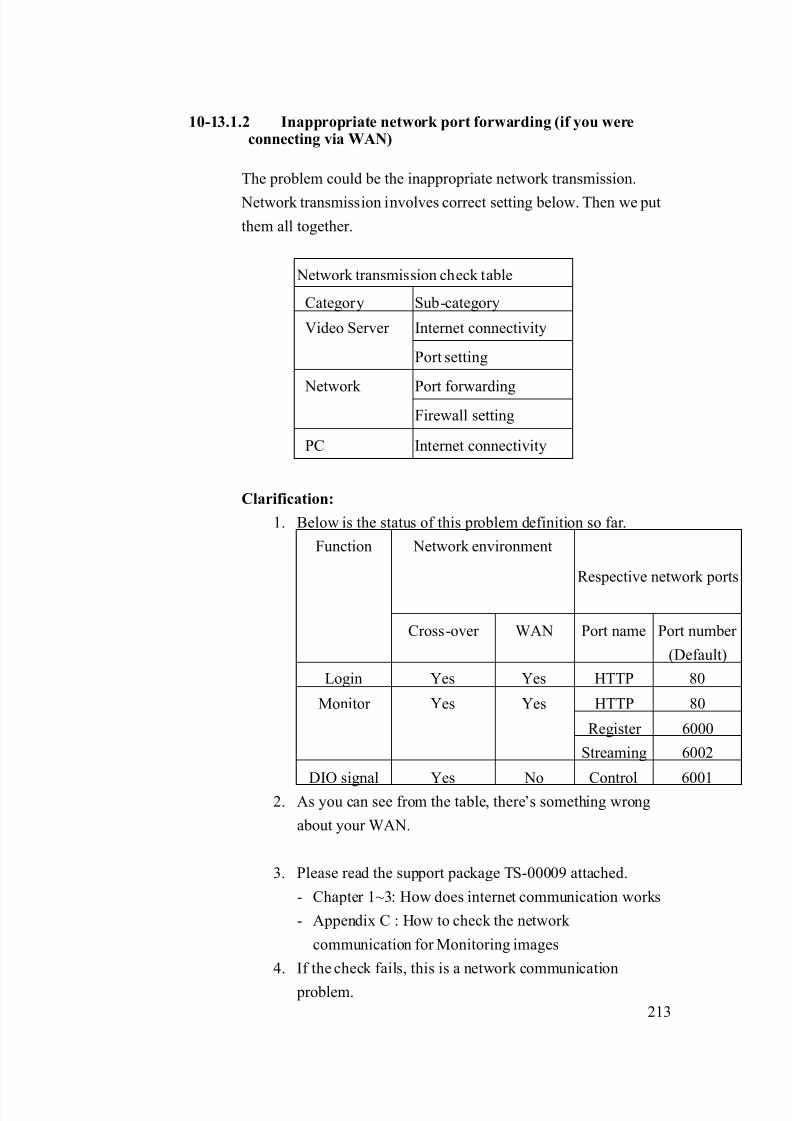
8/21/2019 IP Surveillance TroubleShooting Guide_V0.9
http://slidepdf.com/reader/full/ip-surveillance-troubleshooting-guidev09 215/347
213
10-13.1.2 Inappropriate network port forwarding (if you wereconnecting via WAN)
The problem could be the inappropriate network transmission.
Network transmission involves correct setting below. Then we put
them all together.
Network transmission check table
Category Sub-category
Internet connectivityVideo Server
Port setting
Port forwarding Network Firewall setting
PC Internet connectivity
Clarification:
1. Below is the status of this problem definition so far.
Network environment
Respective network ports
Function
Cross-over WAN Port name Port number
(Default)
Login Yes Yes HTTP 80
HTTP 80
Register 6000
Monitor Yes Yes
Streaming 6002
DIO signal Yes No Control 60012. As you can see from the table, there’s something wrong
about your WAN.
3. Please read the support package TS-00009 attached.
- Chapter 1~3: How does internet communication works
- Appendix C : How to check the network
communication for Monitoring images
4. If the check fails, this is a network communication
problem.

8/21/2019 IP Surveillance TroubleShooting Guide_V0.9
http://slidepdf.com/reader/full/ip-surveillance-troubleshooting-guidev09 216/347
214
5. If the check ok, this is not a network communication
problem.
Solution:
1. Follows the support package TS-00009 to build up the
internet communication step by step. .
10-13.1.3 Blocked by firewall (if you were connecting via WAN)
The problem is discussed in 10-13.1.2, please go there for details.
10-13.1.4 DNS problem (if you were connecting via DNS)
This problem could happen if you connect to the video server/IP
camera using Domain Name (Ex: http://myroom.dyndns.org)
instead of IP address (Ex: http://59.233.23.59).
Clarification:
1. Please switch the software setting from IP address from
Domain Name to IP address and see if you can monitor
the images.
2. If yes, this is a DNS problem.
3. If not, this is not a DNS problem.
Solution:
1. Report the following information to our sales. We will
provide you an updated version A.S.A.P.
Category Description Example:
HardwareModel number
SED-2120
Firmware
version
A1D-V2.00.00
Software model NVR
Software
version
V1.00.00
2. Before you get that updated version, you can use IP
8/21/2019 IP Surveillance TroubleShooting Guide_V0.9
http://slidepdf.com/reader/full/ip-surveillance-troubleshooting-guidev09 217/347
215
address instead of Domain name to connect to the video
server/IP camera a contingency plan.
10-13-2 Storage block
The possible causes could be as below.
10-13.2.1 Inappropriate NVR – E-mail client setting
This problem could happen if you didn’t setup the FTP client
setting in the NVR right.
Clarification:1. Please read the NVR’s software manual for how to setup
the E-mail client setting.
2. Clarify if your settings are right.
3. If yes, this is NOT an inappropriate NVR –E-mail setting
4. If not, this is an inappropriate NVR–E-mail client setting.
Solution:
1. Please refer to the NVR software manual for how tocorrectly set it.
10-13.2.2 Inappropriate NVR – event setting
This problem could happen if you didn’t setup the event setting in
the NVR right.
Clarification:
1. Please read the NVRs software manual for how to setup
the event setting.
2. Clarify if your settings are right.
3. If yes, this is NOT an inappropriate NVR – event setting
4. If not, this is an inappropriate NVR – event client setting.
Solution:
1. Please refer to the NVR’s software manual for how to
correctly set it.

8/21/2019 IP Surveillance TroubleShooting Guide_V0.9
http://slidepdf.com/reader/full/ip-surveillance-troubleshooting-guidev09 218/347
216
10-13-3 If problem not solved, how to report this
problem?
If the solution above can’t solve the problem, please gather the following
information and contact our sales. (Please see introduction about how to
contact).
10-13.3.1 Problem feedback table
Problem feedback table of login problem 1
Category Sub-category Description
Product model Model number
Firmware Firmware version
Use it to connect?
IP address
Submask
Video Server
LAN IP setting
Gateway
Use it to connect?
IP address
Submask
Video Server
WAN IP setting
Gateway
Version
FTP setting
NVR event
Event action
Network diagram Network
deployment Respective setting of
switch / routers.
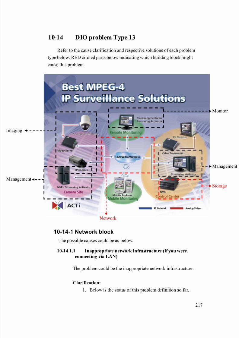
8/21/2019 IP Surveillance TroubleShooting Guide_V0.9
http://slidepdf.com/reader/full/ip-surveillance-troubleshooting-guidev09 219/347
217
10-14 DIO problem Type 13
Refer to the cause clarification and respective solutions of each problem
type below. RED circled parts below indicating which building block mightcause this problem.
10-14-1 Network block
The possible causes could be as below.
10-14.1.1 Inappropriate network infrastructure (if you were
connecting via LAN)
The problem could be the inappropriate network infrastructure.
Clarification:
1. Below is the status of this problem definition so far.
Network
Management
Storage
maging
Monitor
Management

8/21/2019 IP Surveillance TroubleShooting Guide_V0.9
http://slidepdf.com/reader/full/ip-surveillance-troubleshooting-guidev09 220/347
218
Network
environment Respective network ports
Function
Cross-over LAN Port name Port number (Default)
Login Yes Yes HTTP 80
HTTP 80
Register 6000
View image Yes Yes
Streaming 6002
DIO signal Yes No Control 6001
2. As you can see from the table, there’s something wrong
about your LAN.
Solution:
1. Because this problem involves mostly about your LAN
environment, it’s less possible for us to provide the
solution.
2. Please fill in your definition table
Network environment Respective network ports
Function
Cross-over LAN Port name Port number
Login Yes Yes HTTP
HTTP
Register
View image Yes Yes
Streaming
DIO signal Yes No Control
3. Please provide the definition table above to your MIS or
your network architect for this problem. Ask him for
solution.

8/21/2019 IP Surveillance TroubleShooting Guide_V0.9
http://slidepdf.com/reader/full/ip-surveillance-troubleshooting-guidev09 221/347
219
10-14.1.2 Inappropriate network port forwarding (if you wereconnecting via WAN)
The problem could be the inappropriate network transmission.
Network transmission involves correct setting below. Then we put
them all together.
Network transmission check table
Category Sub-category
Internet connectivityVideo Server
Port setting
Port forwarding Network
Firewall setting
PC Internet connectivity
Clarification:
1. Below is the status of this problem definition so far.
Network environment
Respective network ports
Function
Cross-over WAN Port name Port number
(Default)
Login Yes Yes HTTP 80
HTTP 80
Register 6000
Monitor Yes Yes
Streaming 6002
DIO signal Yes No Control 6001
2. As you can see from the table, there’s something wrongabout your WAN.
3. Please read the support package TS-00009 attached.
- Chapter 1~3: How does internet communication works
- Appendix C : How to check the network
communication for Monitoring images
4. If the check fails, this is a network communication
problem.
8/21/2019 IP Surveillance TroubleShooting Guide_V0.9
http://slidepdf.com/reader/full/ip-surveillance-troubleshooting-guidev09 222/347
220
5. If the check ok, this is not a network communication
problem.
Solution:
1. Follows the support package TS-00009 to build up the
internet communication step by step. .
10-14.1.3 Blocked by firewall (if you were connecting via WAN)
The problem is discussed in 10-14.1.2, please go there for details.
10-14.1.4 DNS problem (if you were connecting via DNS)
This problem could happen if you connect to the video server/IP
camera using Domain Name (Ex: http://myroom.dyndns.org)
instead of IP address (Ex: http://59.233.23.59).
Clarification:
1. Please switch the software setting from IP address from
Domain Name to IP address and see if you can monitor
the images.
2. If yes, this is a DNS problem.
3. If not, this is not a DNS problem.
Solution:
1. Report the following information to our sales. We will
provide you an updated version A.S.A.P.
Category Description Example:
HardwareModel number
SED-2120
Firmware
version
A1D-V2.00.00
Software model NVR
Software
version
V1.00.00
2. Before you get that updated version, you can use IP
8/21/2019 IP Surveillance TroubleShooting Guide_V0.9
http://slidepdf.com/reader/full/ip-surveillance-troubleshooting-guidev09 223/347
221
address instead of Domain name to connect to the video
server/IP camera a contingency plan.
10-14-2 Storage block
The possible causes could be as below.
10-14.2.1 Inappropriate NVR – event setting
This problem could happen if you didn’t setup the event setting in
the NVR right.
Clarification:1. Please read the NVR’s software manual for how to setup
the event setting.
2. Clarify if your settings are right.
3. If yes, this is NOT an inappropriate NVR – event setting
4. If not, this is an inappropriate NVR– event client setting.
Solution:
1. Please refer to the NVR’s software manual for how tocorrectly set it.
10-14-3 If problem not solved, how to report thisproblem?
If the solution above can’t solve the problem, please gather the following
information and contact our sales. (Please see introduction about how to
contact).
10-14.3.1 Problem feedback table
Problem feedback table of login problem 1
Category Sub-category Description
Product model Model number
Firmware Firmware version
Use it to connect?Video Server
LAN IP setting IP address

8/21/2019 IP Surveillance TroubleShooting Guide_V0.9
http://slidepdf.com/reader/full/ip-surveillance-troubleshooting-guidev09 224/347
222
Submask
Gateway
Use it to connect?
IP address
Submask
Video Server
WAN IP setting
Gateway
Version NVR event
Event action
Network diagram Network
deployment Respective setting of
switch / routers.

8/21/2019 IP Surveillance TroubleShooting Guide_V0.9
http://slidepdf.com/reader/full/ip-surveillance-troubleshooting-guidev09 225/347
223
10-15 DIO problem Type 14
Refer to the cause clarification and respective solutions of each problem
type below. RED circled parts below indicating which building block mightcause this problem.
10-15-1 Storage block
The possible causes could be as below.
10-15.1.1 Inappropriate recording setting
This problem could happen if your recording settings are wrong.
Clarification:
5. Please read the NVR’s software manual for how to setup
the record setting.
Network
Management
Storage
maging
Monitor
Management
8/21/2019 IP Surveillance TroubleShooting Guide_V0.9
http://slidepdf.com/reader/full/ip-surveillance-troubleshooting-guidev09 226/347
224
6. Clarify if your settings are right.
7. If yes, this is NOT an inappropriate recording – setting.
8. If not, this is an inappropriate recording – setting.
Solution:
2. Please refer to the NVR’s software manual for how to
correctly set it.
10-15.1.2 Inappropriate PC authority
This problem could happen if your have limited PC authority
which will cause you problem when
a. Executing program
b. Save recordings
Clarification:
4. Please check if you login this PC as “Administrator” or
any account with the same authority.
5. If yes, this is NOT an inappropriate PC authority.
6. If not, this is an inappropriate PC authority.
Solution:
2. Always login this PC as “Administrator”.
10-15.1.3 Insufficient HD space
If your HD space is not sufficient, you will have problem recording
files.
Clarification:
5. Open NVR
6. See if there’s HD insufficient warning pop-out right after
you login
7. If not, this is NOT an insufficient HD space.
8. If not, this is an insufficient HD space.
Solution:
8/21/2019 IP Surveillance TroubleShooting Guide_V0.9
http://slidepdf.com/reader/full/ip-surveillance-troubleshooting-guidev09 227/347
225
3. Your system must have enough HD space for software to
record all the time.
4. Please refer to each software’s manual for the space
required.
10-15-2 If problem not solved, how to report this
problem?
If the solution above can’t solve the problem, please gather the following
information and contact our sales. (Please see introduction about how to
contact).
10-15.2.1 Problem feedback table
Problem feedback table of login problem 1
Category Sub-category Description
Product model Model number
Firmware Firmware version
Version
Recording setting
Software
HD spacePC login Authority
(As Admin, power user,
or user)

8/21/2019 IP Surveillance TroubleShooting Guide_V0.9
http://slidepdf.com/reader/full/ip-surveillance-troubleshooting-guidev09 228/347
226
10-16 DIO problem Type 15
Refer to the cause clarification and respective solutions of each problem
type below. RED circled parts below indicating which building block mightcause this problem.
10-16-1 Network block
The possible causes could be as below.
10-16.1.1 Inappropriate network infrastructure (if you were
connecting via LAN)
The problem could be the inappropriate network infrastructure.
Clarification:
1. Below is the status of this problem definition so far.
Network
Management
Storage
maging
Monitor
Management

8/21/2019 IP Surveillance TroubleShooting Guide_V0.9
http://slidepdf.com/reader/full/ip-surveillance-troubleshooting-guidev09 229/347
227
Network
environment Respective network ports
Function
Cross-over LAN Port name Port number (Default)
Login Yes Yes HTTP 80
HTTP 80
Register 6000
View image Yes Yes
Streaming 6002
DIO signal Yes No Control 6001
2. As you can see from the table, there’s something wrong
about your LAN.
Solution:
1. Because this problem involves mostly about your LAN
environment, it’s less possible for us to provide the
solution.
2. Please fill in your definition table
Network environment Respective network ports
Function
Cross-over LAN Port name Port number
Login Yes Yes HTTP
HTTP
Register
View image Yes Yes
Streaming
DIO signal Yes No Control
3. Please provide the definition table above to your MIS or
your network architect for this problem. Ask him for
solution.

8/21/2019 IP Surveillance TroubleShooting Guide_V0.9
http://slidepdf.com/reader/full/ip-surveillance-troubleshooting-guidev09 230/347
228
10-16.1.2 Inappropriate network port forwarding (if you wereconnecting via WAN)
The problem could be the inappropriate network transmission.
Network transmission involves correct setting below. Then we put
them all together.
Network transmission check table
Category Sub-category
Internet connectivityVideo Server
Port setting
Port forwarding Network Firewall setting
PC Internet connectivity
Clarification:
1. Below is the status of this problem definition so far.
Network environment
Respective network ports
Function
Cross-over WAN Port name Port number
(Default)
Login Yes Yes HTTP 80
HTTP 80
Register 6000
Monitor Yes Yes
Streaming 6002
DIO signal Yes No Control 60012. As you can see from the table, there’s something wrong
about your WAN.
3. Please read the support package TS-00009 attached.
- Chapter 1~3: How does internet communication works
- Appendix C : How to check the network
communication for Monitoring images
4. If the check fails, this is a network communication
problem.

8/21/2019 IP Surveillance TroubleShooting Guide_V0.9
http://slidepdf.com/reader/full/ip-surveillance-troubleshooting-guidev09 231/347
229
5. If the check ok, this is not a network communication
problem.
Solution:
1. Follows the support package TS-00009 to build up the
internet communication step by step. .
10-16.1.3 Blocked by firewall (if you were connecting via WAN)
The problem is discussed in 10-16.1.2, please go there for details.
10-16.1.4 DNS problem (if you were connecting via DNS)
This problem could happen if you connect to the video server/IP
camera using Domain Name (Ex: http://myroom.dyndns.org)
instead of IP address (Ex: http://59.233.23.59).
Clarification:
1. Please switch the software setting from IP address from
Domain Name to IP address and see if you can monitor
the images.
2. If yes, this is a DNS problem.
3. If not, this is not a DNS problem.
Solution:
1. Report the following information to our sales. We will
provide you an updated version A.S.A.P.
Category Description Example:
HardwareModel number
SED-2120
Firmware
version
A1D-V2.00.00
Software model NVR
Software
version
V1.00.00
2. Before you get that updated version, you can use IP
8/21/2019 IP Surveillance TroubleShooting Guide_V0.9
http://slidepdf.com/reader/full/ip-surveillance-troubleshooting-guidev09 232/347
230
address instead of Domain name to connect to the video
server/IP camera an a contingency plan.
10-16-2 If problem not solved, how to report thisproblem?
If the solution above can’t solve the problem, please gather the following
information and contact our sales. (Please see introduction about how to
contact).
10-16.2.1 Problem feedback table
Problem feedback table of login problem 1
Category Sub-category Description
Product model Model number
Firmware Firmware version
Use it to connect?
IP address
Submask
Video Server
LAN IP setting
Gateway
Use it to connect?
IP address
Submask
Video Server
WAN IP setting
Gateway
Streaming
Explorer
Version
Network diagram Network
deployment Respective setting of
switch / routers.

8/21/2019 IP Surveillance TroubleShooting Guide_V0.9
http://slidepdf.com/reader/full/ip-surveillance-troubleshooting-guidev09 233/347
231
10-17 DIO problem Type 16
Refer to the cause clarification and respective solutions of each problem
type below. RED circled parts below indicating which building block mightcause this problem.
10-17-1 Image block
The possible causes could be as below.
10-17.1.1 Inappropriate DO devices
The problem can be resulted by
a. Inappropriate DO devices or
b. Inappropriate DO connections
Clarification:
Network
Management
Storage
maging
Monitor
Management

8/21/2019 IP Surveillance TroubleShooting Guide_V0.9
http://slidepdf.com/reader/full/ip-surveillance-troubleshooting-guidev09 234/347
232
1. Please read the support package TS-00045 to clarify if
your DO device spec is right.
2. Please read the support package TS-00045 to clarify if
your DI connection is right.
3. If yes, this is NOT a DO device or DO connection
problem.
4. If not, this is a DO device or DO connection problem
Solution:
1. Please refer to the support package TS-00045 for how to
correctly set it.
10-17.1.2 Inappropriate DO connections
The problem is discussed in 10-17.1.1, please go there for details.
10-17-2 Network block
The possible causes could be as below.
10-17.2.1 Inappropriate network port setting
The problem could be the inappropriate network infrastructure.
Clarification:
1. Check out the port settings below of the web-configurator
and the Streaming Explorer.
Respective network ports
Function
Port name Port number
(Default)
Web-confi
gurator
Streaming
Explorer
Login HTTP 80
HTTP 80
Register 6000
View image
Streaming 6002
DIO signal Control 6001
2. Check if any of the port not the same, this is Inappropriate
8/21/2019 IP Surveillance TroubleShooting Guide_V0.9
http://slidepdf.com/reader/full/ip-surveillance-troubleshooting-guidev09 235/347
233
network port setting problem.
3. Check if all of the port are the same, this is not
Inappropriate network port setting problem.
Solution:
1. Change the control port setting on the streaming explorer
to match the settings on the web-configurator.
10-17-3 If problem not solved, how to report this
problem?
If the solution above can’t solve the problem, please gather the following
information and contact our sales. (Please see introduction about how to
contact).
10-17.3.1 Problem feedback table
Problem feedback table of login problem 1
Category Sub-category Description
Product model Model number
Firmware Firmware version
HTTP port
Streaming Port
Web-configurator
Control port
model
Software version
HTTP port
Streaming Port
Software model
Control port
DO device specDO
DO connection diagram
Other data you
find during
clarification
Server PC

8/21/2019 IP Surveillance TroubleShooting Guide_V0.9
http://slidepdf.com/reader/full/ip-surveillance-troubleshooting-guidev09 236/347
234
Chapter. 11. MD event ProblemIn this Chapter, we will focus the problem that you
1. Can login the video server/IP camera2. Can monitor the image
3. You can’t use the Motion Detection function (Example: You can’t record
every time there’s a motion happening.)
We will provide a diagnostic flow for customer to find out his problem type
within this problem category. Then we will examine the possible cause for each
problem type and find out the root cause and respective solutions.
11-1 Find out the possible cause
Please refer to the diagnostic flows to find out the problem type of the MD
Problem. We define two kinds of MD problem as below
1st: No event: You can’t trigger even when there’s a motion
2nd: False alarm: You have many unwanted motion events.
We have two diagnostic flows for different kinds MD problem. Please refer
to the diagnostic flow to find the and refer to next section for possible cause
clarification and solutions.
11-1-1 No event MD problem diagnostic flow
Check Item Remark
Step1 Check the Control Device
Step2 What MD function do you have problem
with?
(Web-Configurator)
Can you see RED square at the “Video
Adjust” on the web-configurator?
Detailed procedure
will be added in
next version
(Streaming Activator)
Can you see RED square at Motion
Detection setup page while connecting
directly via cross-over cable?
Detailed procedure
will be added in
next version
Step3
(NVR)
Can you see RED square at the “Video
Adjust” on the web-configurator?
Detailed procedure
will be added in
next version
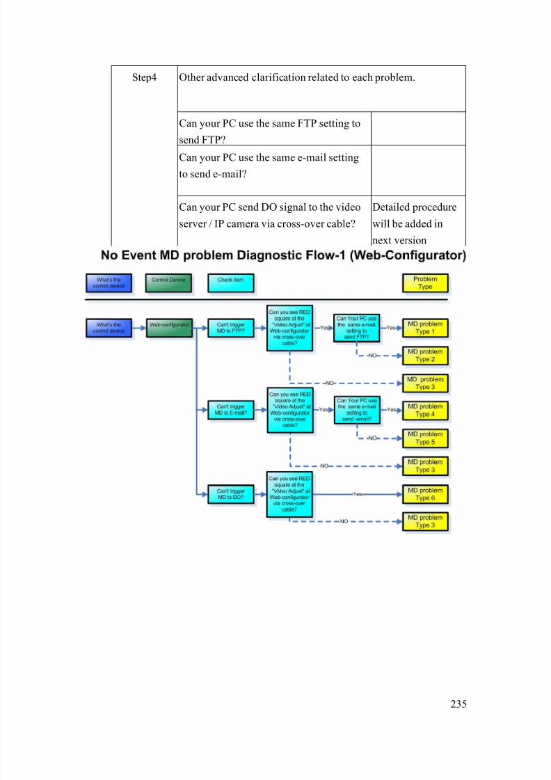
8/21/2019 IP Surveillance TroubleShooting Guide_V0.9
http://slidepdf.com/reader/full/ip-surveillance-troubleshooting-guidev09 237/347
235
Other advanced clarification related to each problem.
Can your PC use the same FTP setting to
send FTP?
Can your PC use the same e-mail setting
to send e-mail?
Step4
Can your PC send DO signal to the video
server / IP camera via cross-over cable?
Detailed procedure
will be added in
next version
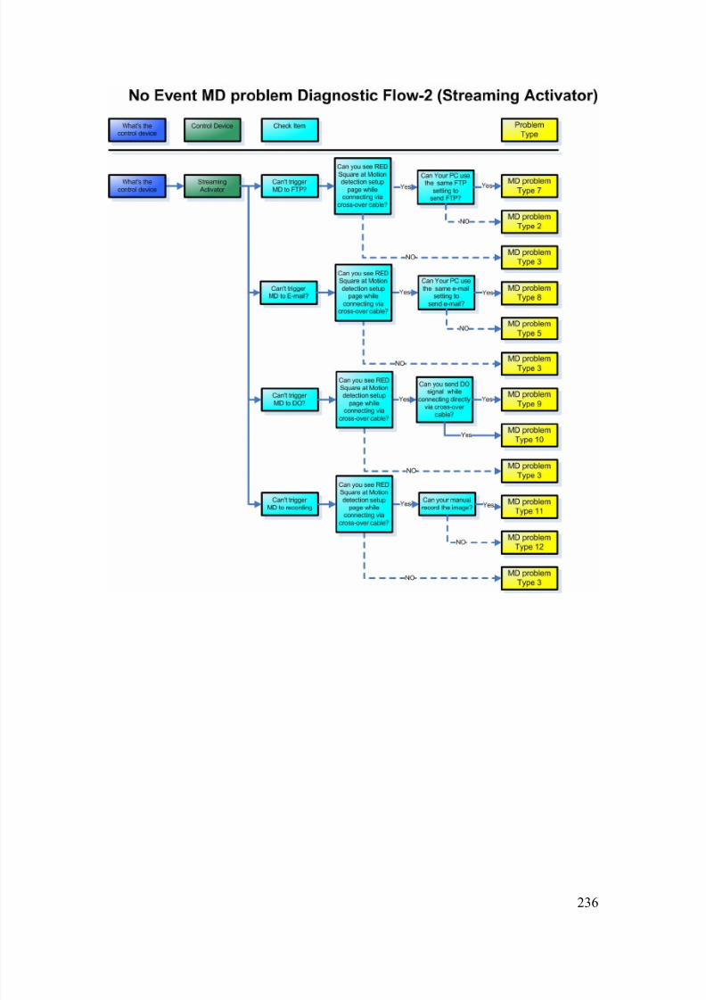
8/21/2019 IP Surveillance TroubleShooting Guide_V0.9
http://slidepdf.com/reader/full/ip-surveillance-troubleshooting-guidev09 238/347
236

8/21/2019 IP Surveillance TroubleShooting Guide_V0.9
http://slidepdf.com/reader/full/ip-surveillance-troubleshooting-guidev09 239/347
237
11-1-2 False alarm MD problem diagnostic flow
Check Item Remark
Step1 Check the Control Device
Step2 Are there a lot of activities in the shooting
theme?
Step3 Are there
1. Constant color shift
2. Constant lighting shift
3. A lot of noises
Detailed procedure
will be added in
next version
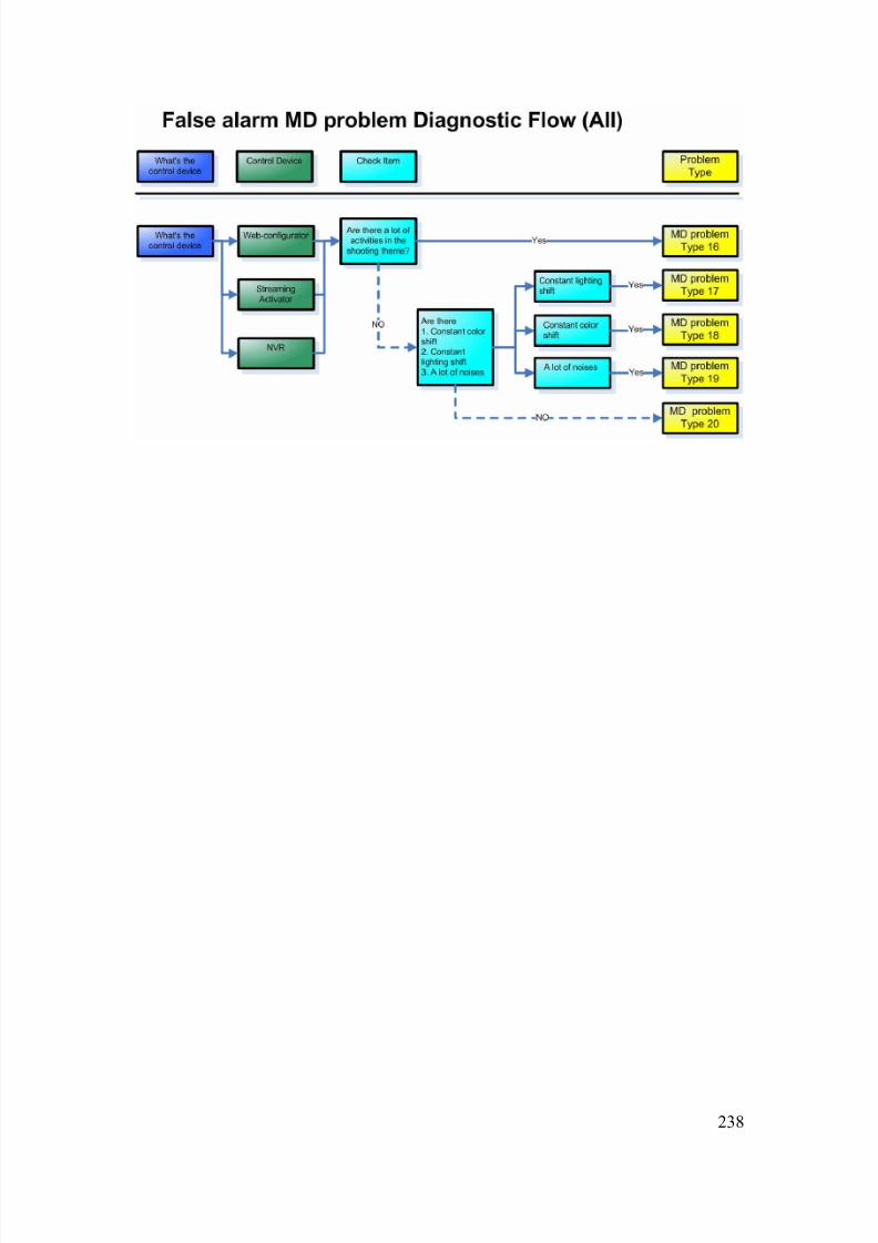
8/21/2019 IP Surveillance TroubleShooting Guide_V0.9
http://slidepdf.com/reader/full/ip-surveillance-troubleshooting-guidev09 240/347
238
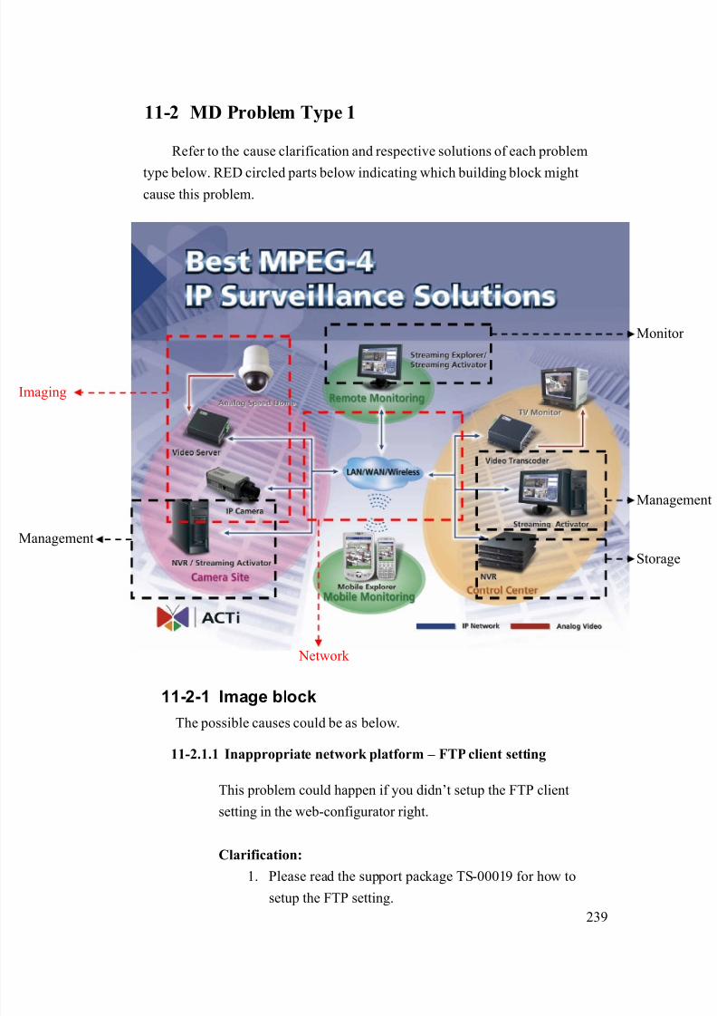
8/21/2019 IP Surveillance TroubleShooting Guide_V0.9
http://slidepdf.com/reader/full/ip-surveillance-troubleshooting-guidev09 241/347
239
11-2 MD Problem Type 1
Refer to the cause clarification and respective solutions of each problem
type below. RED circled parts below indicating which building block mightcause this problem.
11-2-1 Image block
The possible causes could be as below.
11-2.1.1 Inappropriate network platform – FTP client setting
This problem could happen if you didn’t setup the FTP client
setting in the web-configurator right.
Clarification:
1. Please read the support package TS-00019 for how to
setup the FTP setting.
Network
Management
Storage
maging
Monitor
Management
8/21/2019 IP Surveillance TroubleShooting Guide_V0.9
http://slidepdf.com/reader/full/ip-surveillance-troubleshooting-guidev09 242/347
240
2. Clarify if your settings are right.
3. If yes, this is NOT a network platform – FTP client setting
4. If not, this is a network platform – FTP client setting.
Solution:
1. Please refer to the support package TS-00019 for how to
correctly set it.
11-2.1.2 Inappropriate network platform – event setting
This problem could happen if you didn’t setup the event setting in
the web-configurator right.
Clarification:
1. Please read the support package TS-00019 for how to
setup the event setting.
2. Clarify if your settings are right.
3. If yes, this is NOT a network platform – event setting
4. If not, this is a network platform –event setting.
Solution:1. Please refer to the support package TS-00019 for how to
correctly set it.
11-2-2 If problem not solved, how to report thisproblem?
If the solution above can’t solve the problem, please gather the following
information and contact our sales. (Please see introduction about how to
contact).
11-2.2.1 Problem feedback table
Problem feedback table of login problem 1
Category Sub-category Description
Product model Model number
Firmware Firmware version
Video Server Use it to connect?
8/21/2019 IP Surveillance TroubleShooting Guide_V0.9
http://slidepdf.com/reader/full/ip-surveillance-troubleshooting-guidev09 243/347
241
IP address
Submask
LAN IP setting
Gateway
Use it to connect?
IP address
Submask
Video Server
WAN IP setting
Gateway
FTP settingVideo server
event setting Event action
Network diagram Network
deployment Respective setting of
switch / routers.
.
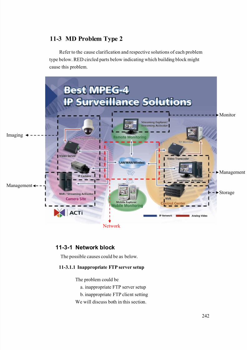
8/21/2019 IP Surveillance TroubleShooting Guide_V0.9
http://slidepdf.com/reader/full/ip-surveillance-troubleshooting-guidev09 244/347
242
11-3 MD Problem Type 2
Refer to the cause clarification and respective solutions of each problem
type below. RED circled parts below indicating which building block mightcause this problem.
11-3-1 Network block
The possible causes could be as below.
11-3.1.1 Inappropriate FTP server setup
The problem could be
a. inappropriate FTP server setup
b. inappropriate FTP client setting
We will discuss both in this section.
Network
Management
Storage
maging
Monitor
Management

8/21/2019 IP Surveillance TroubleShooting Guide_V0.9
http://slidepdf.com/reader/full/ip-surveillance-troubleshooting-guidev09 245/347
243
Clarification:
1. Because you fail to connect the FTP setting using your
own PC, that means there’s something wrong about the
a. FTP server setup and
b. FTP client setting.
2. Because this problem involves mostly about your network
and MIS infrastructure, it ’s less possible for us to provide
the solution.
Solution:
1. Please provide the following item and give it to your MIS
or your network architect for this problem. Ask him for
solution.
Category Sub-category Settings
Server PCFTP server
Other
Server IP
Account
Password
File Path
FTP Client
Other
11-3.1.2 Inappropriate FTP client setting (account and password)
The problem is discussed in 10-3.1.1, please go there for details
11-3-2 If problem not solved, how to report this
problem?
If the solution above can’t solve the problem, please gather the following
information and contact our sales. (Please see introduction about how to
contact).

8/21/2019 IP Surveillance TroubleShooting Guide_V0.9
http://slidepdf.com/reader/full/ip-surveillance-troubleshooting-guidev09 246/347
244
11-3.2.1 Problem feedback table
Problem feedback table of login problem 1
Category Sub-category Description
Product model Model number
Firmware Firmware version
Use it to connect?
IP address
Submask
Video Server
LAN IP setting
Gateway
Use it to connect?
IP address
Submask
Video Server
WAN IP setting
Gateway
FTP settingVideo server
event setting Event action
Server PCFTP server
Other
Server IP
Account
Password
File Path
FTP Client
Other

8/21/2019 IP Surveillance TroubleShooting Guide_V0.9
http://slidepdf.com/reader/full/ip-surveillance-troubleshooting-guidev09 247/347
245
11-4 MD Problem Type 3
Refer to the cause clarification and respective solutions of each problem
type below. RED circled parts below indicating which building block mightcause this problem.
11-4-1 Image block
The possible causes could be as below.
11-4.1.1 Inappropriate network platform – MD setting
The problem could be that the MD setup procedure wrong.
Clarification:
1. Please recheck the testing procedure and see if the MD
setting’s wrong again.
Network
Management
Storage
maging
Monitor
Management
8/21/2019 IP Surveillance TroubleShooting Guide_V0.9
http://slidepdf.com/reader/full/ip-surveillance-troubleshooting-guidev09 248/347
246
2. If not, this is an inappropriate network platform – MD
setting problem.
3. If yes, let’s look at the problem scenario,
a. you are connecting via cross-over cable
b. you follow the test procedure
4. It’s less possible for you to have network problem and
software setup problem. Thus, it would still be an
inappropriate network platform – MD setting problem.
Solution:
1. Please follow the firmware manual for how to setup
correctly. .
11-4-2 If problem not solved, how to report this
problem?
If the solution above can’t solve the problem, please gather the following
information and contact our sales. (Please see introduction about how to
contact).
11-4.2.1 Problem feedback table
Problem feedback table of login problem 1
Category Sub-category Description
Product model Model number
Firmware Firmware version
How do you set?Video Server
MD setting What do you see after
you set it?
Other
information you
find during
clarification

8/21/2019 IP Surveillance TroubleShooting Guide_V0.9
http://slidepdf.com/reader/full/ip-surveillance-troubleshooting-guidev09 249/347
247
11-5 MD Problem Type 4
Refer to the cause clarification and respective solutions of each problem
type below. RED circled parts below indicating which building block mightcause this problem.
11-5-1 Image block
The possible causes could be as below.
11-5.1.1 Inappropriate network platform – E-mail client setting
This problem could happen if you didn’t setup the FTP client
setting in the web-configurator right.
Clarification:
1. Please read the support package TS-00019 for how to
setup the e-mail client setting.
Network
Management
Storage
maging
Monitor
Management

8/21/2019 IP Surveillance TroubleShooting Guide_V0.9
http://slidepdf.com/reader/full/ip-surveillance-troubleshooting-guidev09 250/347
248
2. Clarify if your settings are right.
3. If yes, this is NOT a network platform –e-mail client
setting
4. If not, this is a network platform –e-mail client setting.
Solution:
1. Please refer to the support package TS-00019 for how to
correctly set it.
11-5.1.2 Inappropriate network platform – event setting
This problem could happen if you didn’t setup the event setting in
the web-configurator right.
Clarification:
1. Please read the support package TS-00019 for how to
setup the event setting.
2. Clarify if your settings are right.
3. If yes, this is NOT a network platform – event setting
4. If not, this is a network platform –event setting.
Solution:
1. Please refer to the support package TS-00019 for how to
correctly set it.
11-5-2 If problem not solved, how to report thisproblem?
If the solution above can’t solve the problem, please gather the following
information and contact our sales. (Please see introduction about how to
contact).
11-5.2.1 Problem feedback table
Problem feedback table of login problem 1
Category Sub-category Description
Product model Model number
Firmware Firmware version

8/21/2019 IP Surveillance TroubleShooting Guide_V0.9
http://slidepdf.com/reader/full/ip-surveillance-troubleshooting-guidev09 251/347
249
Use it to connect?
IP address
Submask
Video Server
LAN IP setting
Gateway
Use it to connect?
IP address
Submask
Video Server
WAN IP setting
Gateway
E-mail settingVideo server
event setting Event action
Network diagram Network
deployment Respective setting of
switch / routers.
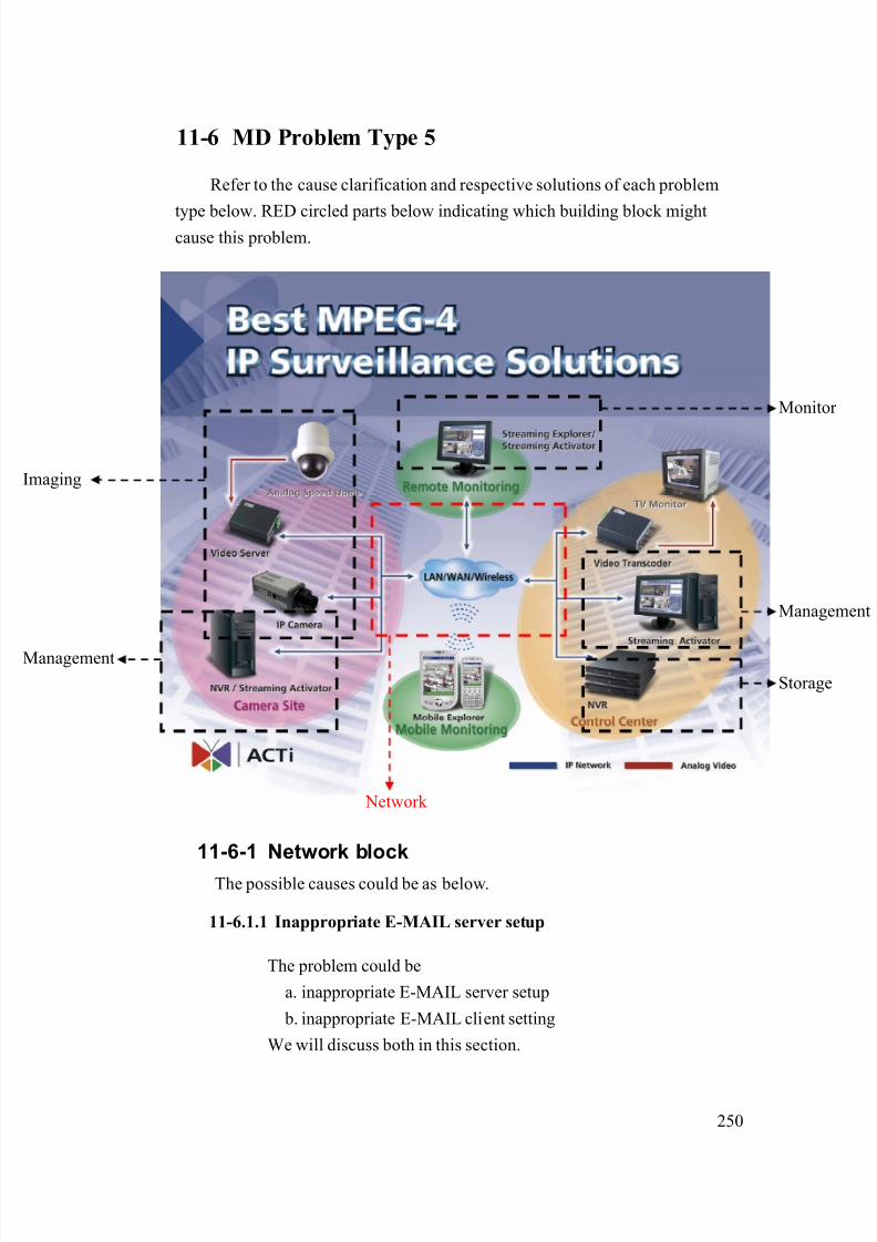
8/21/2019 IP Surveillance TroubleShooting Guide_V0.9
http://slidepdf.com/reader/full/ip-surveillance-troubleshooting-guidev09 252/347
250
11-6 MD Problem Type 5
Refer to the cause clarification and respective solutions of each problem
type below. RED circled parts below indicating which building block mightcause this problem.
11-6-1 Network block
The possible causes could be as below.
11-6.1.1 Inappropriate E-MAIL server setup
The problem could be
a. inappropriate E-MAIL server setup
b. inappropriate E-MAIL client setting
We will discuss both in this section.
Network
Management
Storage
maging
Monitor
Management
8/21/2019 IP Surveillance TroubleShooting Guide_V0.9
http://slidepdf.com/reader/full/ip-surveillance-troubleshooting-guidev09 253/347
251
Clarification:
1. Because you fail to connect the E-MAIL setting using
your own PC, that means there’s something wrong about
the
a. E-MAIL server setup and
b. E-MAIL client setting.
2. Because this problem involves mostly about your network
and MIS infrastructure, it’s less possible for us to provide
the solution.
Solution:
1. Please provide the following item and give it to your MIS
or your network architect for this problem. Ask him for
solution.
Category Sub-category Settings
Server PCE-MAIL
server Other
Server IP
Account
Password
File Path
Client
Other
11-6.1.2 Inappropriate E-MAIL client setting (account and password)
The problem is discussed in 11-6.1.1, please go there for details
11-6-2 If problem not solved, how to report this
problem?
If the solution above can’t solve the problem, please gather the following
information and contact our sales. (Please see introduction about how to
contact).
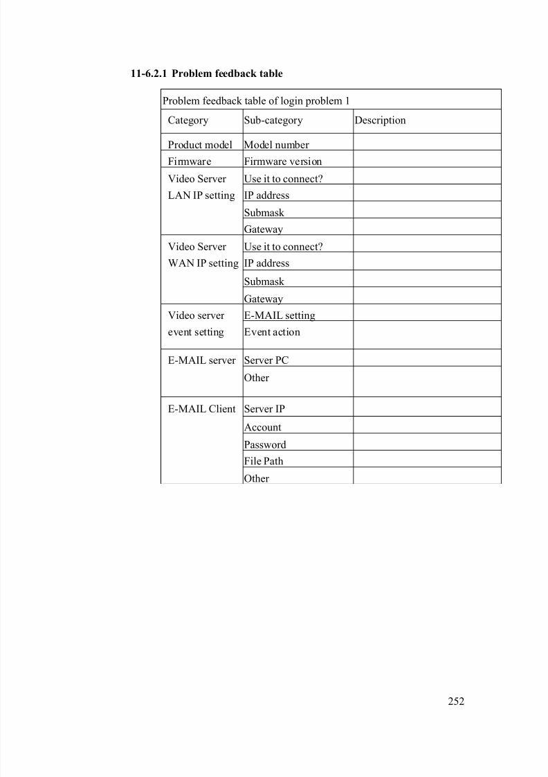
8/21/2019 IP Surveillance TroubleShooting Guide_V0.9
http://slidepdf.com/reader/full/ip-surveillance-troubleshooting-guidev09 254/347
252
11-6.2.1 Problem feedback table
Problem feedback table of login problem 1
Category Sub-category Description
Product model Model number
Firmware Firmware version
Use it to connect?
IP address
Submask
Video Server
LAN IP setting
Gateway
Use it to connect?
IP address
Submask
Video Server
WAN IP setting
Gateway
E-MAIL settingVideo server
event setting Event action
Server PCE-MAIL server
Other
Server IP
Account
Password
File Path
E-MAIL Client
Other

8/21/2019 IP Surveillance TroubleShooting Guide_V0.9
http://slidepdf.com/reader/full/ip-surveillance-troubleshooting-guidev09 255/347
253
11-7 MD Problem Type 6
Refer to the cause clarification and respective solutions of each problem
type below. RED circled parts below indicating which building block mightcause this problem.
11-7-1 Image block
The possible causes could be as below.
11-7.1.1 Inappropriate DO devices
The problem can be resulted by
a. Inappropriate DO devices or
b. Inappropriate DO connections
Network
Management
Storage
maging
Monitor
Management
8/21/2019 IP Surveillance TroubleShooting Guide_V0.9
http://slidepdf.com/reader/full/ip-surveillance-troubleshooting-guidev09 256/347
254
Clarification:
1. Please read the support package TS-00045 to clarify if
your DO device spec is right.
2. Please read the support package TS-00045 to clarify if
your DI connection is right.
3. If yes, this is NOT a DO device or DO connection
problem.
4. If not, this is a DO device or DO connection problem
Solution:
1. Please refer to the support package TS-00045 for how to
correctly set it.
11-7.1.2 Inappropriate DO connections
The problem is discussed in 10-8.1.1, please go there for details.
11-7.1.3 Inappropriate network platform – event setting
This problem could happen if you didn’t setup the event setting in
the web-configurator right.
Clarification:
1. Please read the support package TS-00019 for how to
setup the event setting.
2. Clarify if your settings are right.
3. If yes, this is NOT a network platform – event setting
4. If not, this is a network platform –event setting.
Solution:
2. Please refer to the support package TS-00019 for how to
correctly set it.
11-7-2 If problem not solved, how to report thisproblem?
If the solution above can’t solve the problem, please gather the following
information and contact our sales. (Please see introduction about how to
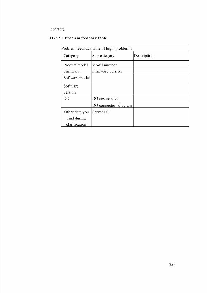
8/21/2019 IP Surveillance TroubleShooting Guide_V0.9
http://slidepdf.com/reader/full/ip-surveillance-troubleshooting-guidev09 257/347
255
contact).
11-7.2.1 Problem feedback table
Problem feedback table of login problem 1
Category Sub-category Description
Product model Model number
Firmware Firmware version
Software model
Software
version
DO device specDO
DO connection diagram
Other data you
find during
clarification
Server PC

8/21/2019 IP Surveillance TroubleShooting Guide_V0.9
http://slidepdf.com/reader/full/ip-surveillance-troubleshooting-guidev09 258/347
256
11-8 MD Problem Type 7
Refer to the cause clarification and respective solutions of each problem
type below. RED circled parts below indicating which building block mightcause this problem.
11-8-1 Network block
The possible causes could be as below.
11-8.1.1 Inappropriate network infrastructure (if you were connecting
via LAN)
The problem could be the inappropriate network infrastructure.
Clarification:
1. Below is the status of this problem definition so far.
Network
Management
Storage
maging
Monitor
Management

8/21/2019 IP Surveillance TroubleShooting Guide_V0.9
http://slidepdf.com/reader/full/ip-surveillance-troubleshooting-guidev09 259/347
257
Network
environment Respective network ports
Function
Cross-over LAN Port name Port number (Default)
Login Yes Yes HTTP 80
HTTP 80
Register 6000
View image Yes Yes
Streaming 6002
MD signal Yes No Control 6001
2. As you can see from the table, there’s something wrong
about your LAN.
Solution:
1. Because this problem involves mostly about your LAN
environment, it’s less possible for us to provide the
solution.
2. Please fill in your definition table
Network environment Respective network ports
Function
Cross-over LAN Port name Port number
Login Yes Yes HTTP
HTTP
Register
View image Yes Yes
Streaming
MD signal Yes No Control
3. Please provide the definition table above to your MIS or
your network architect for this problem. Ask him for
solution.

8/21/2019 IP Surveillance TroubleShooting Guide_V0.9
http://slidepdf.com/reader/full/ip-surveillance-troubleshooting-guidev09 260/347
258
11-8.1.2 Inappropriate network port forwarding (if you wereconnecting via WAN)
The problem could be the inappropriate network transmission.
Network transmission involves correct setting below. Then we put
them all together.
Network transmission check table
Category Sub-category
Internet connectivityVideo Server
Port setting
Port forwarding Network
Firewall setting
PC Internet connectivity
Clarification:
1. Below is the status of this problem definition so far.
Network environment
Respective network ports
Function
Cross-over WAN Port name Port number
(Default)
Login Yes Yes HTTP 80
HTTP 80
Register 6000
Monitor Yes Yes
Streaming 6002
MD signal Yes No Control 6001
2. As you can see from the table, there’s something wrongabout your WAN.
3. Please read the support package TS-00009 attached.
- Chapter 1~3: How does internet communication works
- Appendix C : How to check the network
communication for Monitoring images
4. If the check fails, this is a network communication
problem.
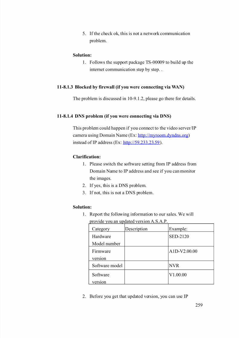
8/21/2019 IP Surveillance TroubleShooting Guide_V0.9
http://slidepdf.com/reader/full/ip-surveillance-troubleshooting-guidev09 261/347
259
5. If the check ok, this is not a network communication
problem.
Solution:
1. Follows the support package TS-00009 to build up the
internet communication step by step. .
11-8.1.3 Blocked by firewall (if you were connecting via WAN)
The problem is discussed in 10-9.1.2, please go there for details.
11-8.1.4 DNS problem (if you were connecting via DNS)
This problem could happen if you connect to the video server/IP
camera using Domain Name (Ex: http://myroom.dyndns.org)
instead of IP address (Ex: http://59.233.23.59).
Clarification:
1. Please switch the software setting from IP address from
Domain Name to IP address and see if you can monitor
the images.
2. If yes, this is a DNS problem.
3. If not, this is not a DNS problem.
Solution:
1. Report the following information to our sales. We will
provide you an updated version A.S.A.P.
Category Description Example:
HardwareModel number
SED-2120
Firmware
version
A1D-V2.00.00
Software model NVR
Software
version
V1.00.00
2. Before you get that updated version, you can use IP
8/21/2019 IP Surveillance TroubleShooting Guide_V0.9
http://slidepdf.com/reader/full/ip-surveillance-troubleshooting-guidev09 262/347
260
address instead of Domain name to connect to the video
server/IP camera an a contingency plan.
11-8-2 Management block
The possible causes could be as below.
11-8.2.1 Inappropriate Streaming Activator – FTP client setting
This problem could happen if you didn’t setup the FTP client
setting in the Streaming Activator right.
Clarification:1. Please read the Streaming Activator’s software manual for
how to setup the FTP client setting.
2. Clarify if your settings are right.
3. If yes, this is NOT an inappropriate Streaming Activator –
FTP setting
4. If not, this is an inappropriate Streaming Activator – FTP
client setting.
Solution:
1. Please refer to the Streaming Activator’s software manual
for how to correctly set it.
11-8.2.2 Inappropriate Streaming Activator – event setting
This problem could happen if you didn’t setup the event setting in
the Streaming Activator right.
Clarification:
1. Please read the Streaming Activator’s software manual for
how to setup the event setting.
2. Clarify if your settings are right.
3. If yes, this is NOT an inappropriate Streaming Activator –
event setting
4. If not, this is an inappropriate Streaming Activator – event
client setting.

8/21/2019 IP Surveillance TroubleShooting Guide_V0.9
http://slidepdf.com/reader/full/ip-surveillance-troubleshooting-guidev09 263/347
261
Solution:
1. Please refer to the Streaming Activator’s software manual
for how to correctly set it.
11-8-3 If problem not solved, how to report this
problem?
If the solution above can’t solve the problem, please gather the following
information and contact our sales. (Please see introduction about how to
contact).
11-8.3.1 Problem feedback table
Problem feedback table of login problem 1
Category Sub-category Description
Product model Model number
Firmware Firmware version
Use it to connect?
IP address
Submask
Video Server
LAN IP setting
Gateway
Use it to connect?
IP address
Submask
Video Server
WAN IP setting
Gateway
Version
FTP setting
Streaming
Activator event
Event action
Network diagram Network
deployment Respective setting of
switch / routers.
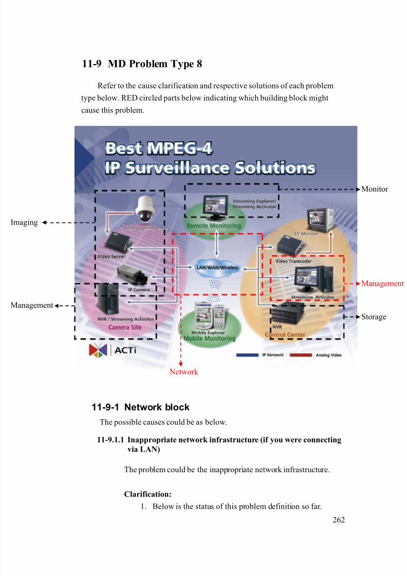
8/21/2019 IP Surveillance TroubleShooting Guide_V0.9
http://slidepdf.com/reader/full/ip-surveillance-troubleshooting-guidev09 264/347
262
11-9 MD Problem Type 8
Refer to the cause clarification and respective solutions of each problem
type below. RED circled parts below indicating which building block mightcause this problem.
11-9-1 Network block
The possible causes could be as below.
11-9.1.1 Inappropriate network infrastructure (if you were connecting
via LAN)
The problem could be the inappropriate network infrastructure.
Clarification:
1. Below is the status of this problem definition so far.
Network
Management
Storage
maging
Monitor
Management
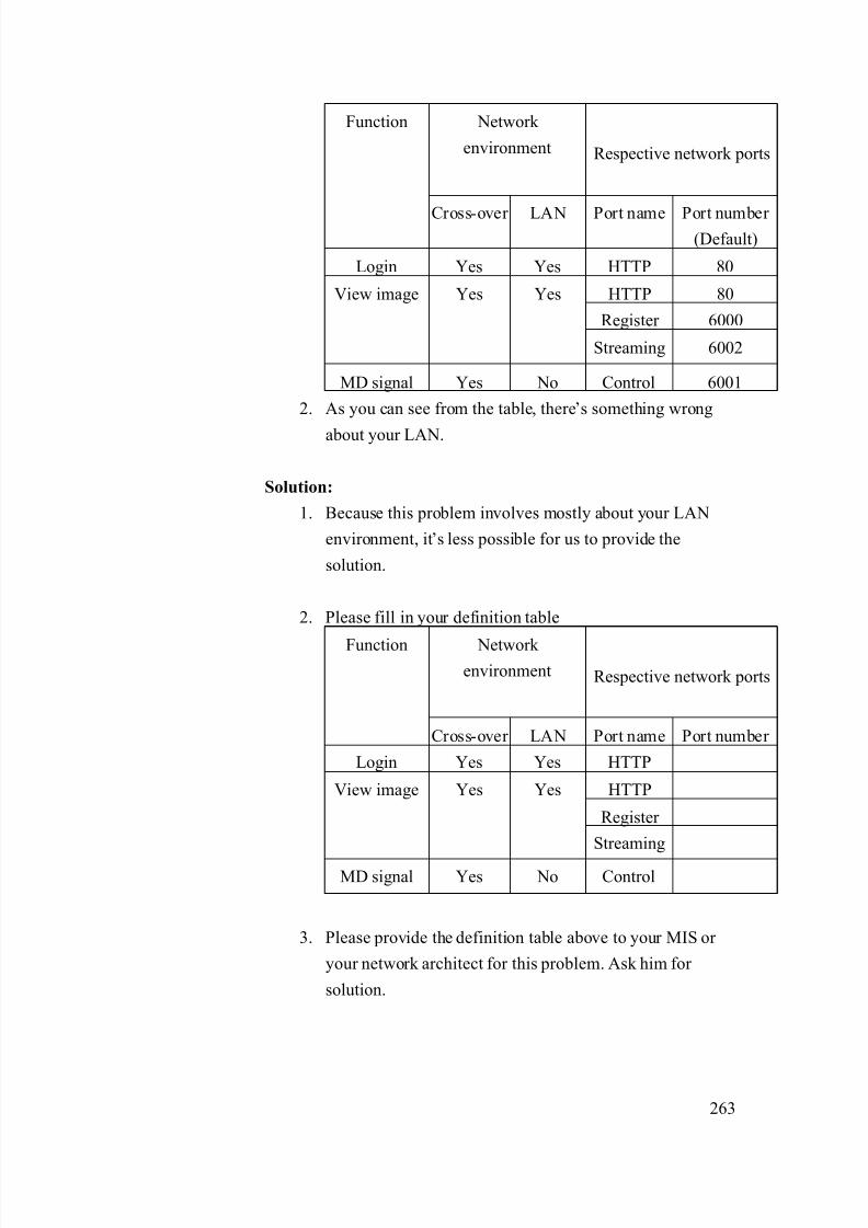
8/21/2019 IP Surveillance TroubleShooting Guide_V0.9
http://slidepdf.com/reader/full/ip-surveillance-troubleshooting-guidev09 265/347
263
Network
environment Respective network ports
Function
Cross-over LAN Port name Port number (Default)
Login Yes Yes HTTP 80
HTTP 80
Register 6000
View image Yes Yes
Streaming 6002
MD signal Yes No Control 6001
2. As you can see from the table, there’s something wrong
about your LAN.
Solution:
1. Because this problem involves mostly about your LAN
environment, it’s less possible for us to provide the
solution.
2. Please fill in your definition table
Network environment Respective network ports
Function
Cross-over LAN Port name Port number
Login Yes Yes HTTP
HTTP
Register
View image Yes Yes
Streaming
MD signal Yes No Control
3. Please provide the definition table above to your MIS or
your network architect for this problem. Ask him for
solution.

8/21/2019 IP Surveillance TroubleShooting Guide_V0.9
http://slidepdf.com/reader/full/ip-surveillance-troubleshooting-guidev09 266/347
264
11-9.1.2 Inappropriate network port forwarding (if you wereconnecting via WAN)
The problem could be the inappropriate network transmission.
Network transmission involves correct setting below. Then we put
them all together.
Network transmission check table
Category Sub-category
Internet connectivityVideo Server
Port setting
Port forwarding Network
Firewall setting
PC Internet connectivity
Clarification:
1. Below is the status of this problem definition so far.
Network environment
Respective network ports
Function
Cross-over WAN Port name Port number
(Default)
Login Yes Yes HTTP 80
HTTP 80
Register 6000
Monitor Yes Yes
Streaming 6002
MD signal Yes No Control 6001
2. As you can see from the table, there’s something wrongabout your WAN.
3. Please read the support package TS-00009 attached.
- Chapter 1~3: How does internet communication works
- Appendix C : How to check the network
communication for Monitoring images
4. If the check fails, this is a network communication
problem.

8/21/2019 IP Surveillance TroubleShooting Guide_V0.9
http://slidepdf.com/reader/full/ip-surveillance-troubleshooting-guidev09 267/347
265
5. If the check ok, this is not a network communication
problem.
Solution:
1. Follows the support package TS-00009 to build up the
internet communication step by step. .
11-9.1.3 Blocked by firewall (if you were connecting via WAN)
The problem is discussed in 11-9.1.2, please go there for details.
11-9.1.4 DNS problem (if you were connecting via DNS)
This problem could happen if you connect to the video server/IP
camera using Domain Name (Ex: http://myroom.dyndns.org)
instead of IP address (Ex: http://59.233.23.59).
Clarification:
1. Please switch the software setting from IP address from
Domain Name to IP address and see if you can monitor
the images.
2. If yes, this is a DNS problem.
3. If not, this is not a DNS problem.
Solution:
1. Report the following information to our sales. We will
provide you an updated version A.S.A.P.
Category Description Example:
HardwareModel number
SED-2120
Firmware
version
A1D-V2.00.00
Software model NVR
Software
version
V1.00.00
2. Before you get that updated version, you can use IP

8/21/2019 IP Surveillance TroubleShooting Guide_V0.9
http://slidepdf.com/reader/full/ip-surveillance-troubleshooting-guidev09 268/347
266
address instead of Domain name to connect to the video
server/IP camera an a contingency plan.
11-9-2 Management block
The possible causes could be as below.
11-9.2.1 Inappropriate Streaming Activator – e-mail client setting
This problem could happen if you didn’t setup the e-mail client
setting in the Streaming Activator right.
Clarification:1. Please read the Streaming Activator’s software manual for
how to setup the e-mail client setting.
2. Clarify if your settings are right.
3. If yes, this is NOT an inappropriate Streaming
Activator –e-mail client setting
4. If not, this is an inappropriate Streaming Activator –
e-mail client setting.
Solution:
1. Please refer to the Streaming Activator’s software manual
for how to correctly set it.
11-9.2.2 Inappropriate Streaming Activator – event setting
This problem could happen if you didn’t setup the event setting in
the Streaming Activator right.
Clarification:
1. Please read the Streaming Activator’s software manual for
how to setup the event setting.
2. Clarify if your settings are right.
3. If yes, this is NOT an inappropriate Streaming Activator –
event setting
4. If not, this is an inappropriate Streaming Activator – event
client setting.

8/21/2019 IP Surveillance TroubleShooting Guide_V0.9
http://slidepdf.com/reader/full/ip-surveillance-troubleshooting-guidev09 269/347
267
Solution:
1. Please refer to the Streaming Activator’s software manual
for how to correctly set it.
11-9-3 If problem not solved, how to report this
problem?
If the solution above can’t solve the problem, please gather the following
information and contact our sales. (Please see introduction about how to
contact).
11-9.3.1 Problem feedback table
Problem feedback table of login problem 1
Category Sub-category Description
Product model Model number
Firmware Firmware version
Use it to connect?
IP address
Submask
Video Server
LAN IP setting
Gateway
Use it to connect?
IP address
Submask
Video Server
WAN IP setting
Gateway
Version
E-mail setting
Streaming
Activator event
Event action
Network diagram Network
deployment Respective setting of
switch / routers.

8/21/2019 IP Surveillance TroubleShooting Guide_V0.9
http://slidepdf.com/reader/full/ip-surveillance-troubleshooting-guidev09 270/347
268
11-10 MD Problem Type 9
Refer to the cause clarification and respective solutions of each problem
type below. RED circled parts below indicating which building block mightcause this problem.
11-10-1 Network block
The possible causes could be as below.
11-10.1.1 Inappropriate network infrastructure (if you were
connecting via LAN)
The problem could be the inappropriate network infrastructure.
Clarification:
1. Below is the status of this problem definition so far.
Network
Management
Storage
maging
Monitor
Management

8/21/2019 IP Surveillance TroubleShooting Guide_V0.9
http://slidepdf.com/reader/full/ip-surveillance-troubleshooting-guidev09 271/347
269
Network
environment Respective network ports
Function
Cross-over LAN Port name Port number (Default)
Login Yes Yes HTTP 80
HTTP 80
Register 6000
View image Yes Yes
Streaming 6002
MD signal Yes No Control 6001
2. As you can see from the table, there’s something wrong
about your LAN.
Solution:
1. Because this problem involves mostly about your LAN
environment, it’s less possible for us to provide the
solution.
2. Please fill in your definition table
Network environment Respective network ports
Function
Cross-over LAN Port name Port number
Login Yes Yes HTTP
HTTP
Register
View image Yes Yes
Streaming
MD signal Yes No Control
3. Please provide the definition table above to your MIS or
your network architect for this problem. Ask him for
solution.

8/21/2019 IP Surveillance TroubleShooting Guide_V0.9
http://slidepdf.com/reader/full/ip-surveillance-troubleshooting-guidev09 272/347
270
11-10.1.2 Inappropriate network port forwarding (if you wereconnecting via WAN)
The problem could be the inappropriate network transmission.
Network transmission involves correct setting below. Then we put
them all together.
Network transmission check table
Category Sub-category
Internet connectivityVideo Server
Port setting
Port forwarding Network
Firewall setting
PC Internet connectivity
Clarification:
1. Below is the status of this problem definition so far.
Network environment
Respective network ports
Function
Cross-over WAN Port name Port number
(Default)
Login Yes Yes HTTP 80
HTTP 80
Register 6000
Monitor Yes Yes
Streaming 6002
MD signal Yes No Control 6001
2. As you can see from the table, there’s something wrongabout your WAN.
3. Please read the support package TS-00009 attached.
- Chapter 1~3: How does internet communication works
- Appendix C : How to check the network
communication for Monitoring images
4. If the check fails, this is a network communication
problem.

8/21/2019 IP Surveillance TroubleShooting Guide_V0.9
http://slidepdf.com/reader/full/ip-surveillance-troubleshooting-guidev09 273/347
271
5. If the check ok, this is not a network communication
problem.
Solution:
1. Follows the support package TS-00009 to build up the
internet communication step by step. .
11-10.1.3 Blocked by firewall (if you were connecting via WAN)
The problem is discussed in 11-9.1.2, please go there for details.
11-10.1.4 DNS problem (if you were connecting via DNS)
This problem could happen if you connect to the video server/IP
camera using Domain Name (Ex: http://myroom.dyndns.org)
instead of IP address (Ex: http://59.233.23.59).
Clarification:
1. Please switch the software setting from IP address from
Domain Name to IP address and see if you can monitor
the images.
2. If yes, this is a DNS problem.
3. If not, this is not a DNS problem.
Solution:
1. Report the following information to our sales. We will
provide you an updated version A.S.A.P.
Category Description Example:
HardwareModel number
SED-2120
Firmware
version
A1D-V2.00.00
Software model NVR
Software
version
V1.00.00
2. Before you get that updated version, you can use IP
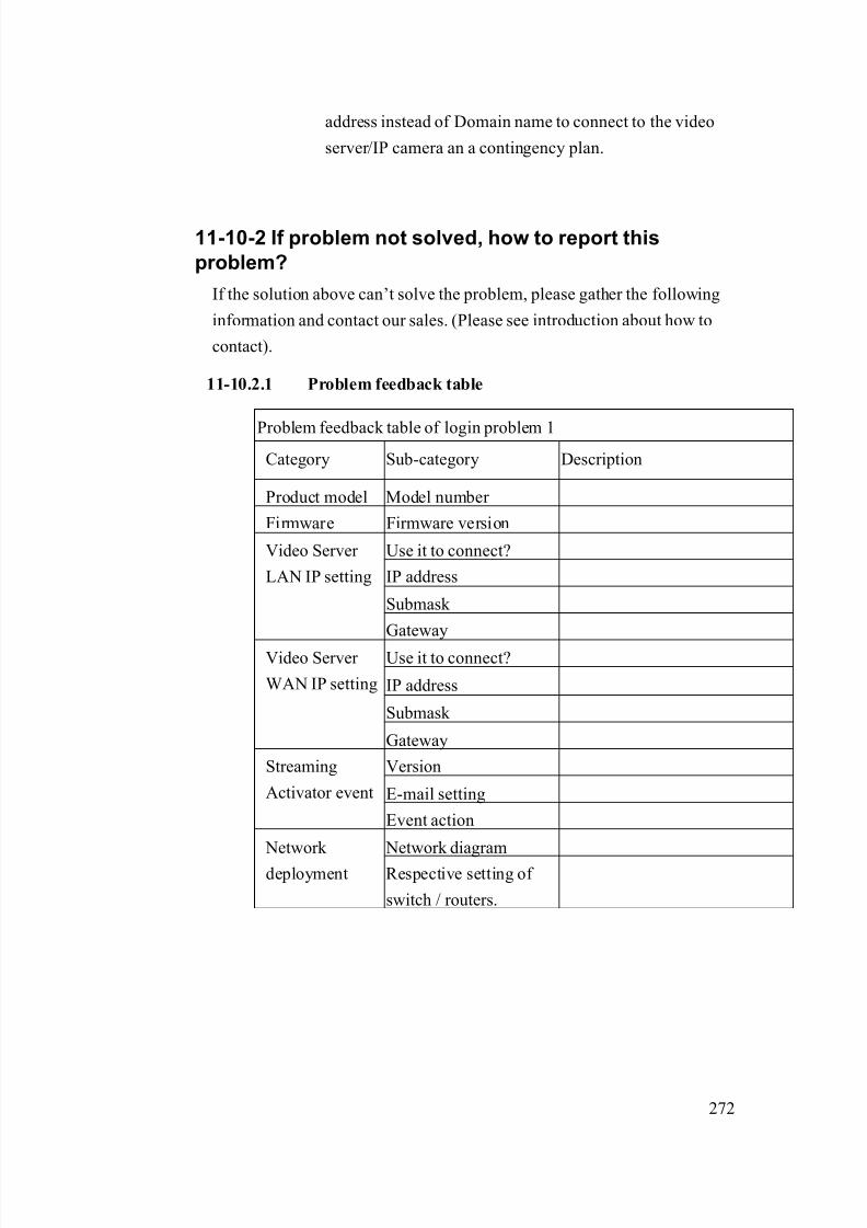
8/21/2019 IP Surveillance TroubleShooting Guide_V0.9
http://slidepdf.com/reader/full/ip-surveillance-troubleshooting-guidev09 274/347
272
address instead of Domain name to connect to the video
server/IP camera an a contingency plan.
11-10-2 If problem not solved, how to report this
problem?
If the solution above can’t solve the problem, please gather the following
information and contact our sales. (Please see introduction about how to
contact).
11-10.2.1 Problem feedback table
Problem feedback table of login problem 1
Category Sub-category Description
Product model Model number
Firmware Firmware version
Use it to connect?
IP address
Submask
Video Server
LAN IP setting
Gateway
Use it to connect?
IP address
Submask
Video Server
WAN IP setting
Gateway
Version
E-mail setting
Streaming
Activator event
Event action
Network diagram Network
deployment Respective setting of
switch / routers.

8/21/2019 IP Surveillance TroubleShooting Guide_V0.9
http://slidepdf.com/reader/full/ip-surveillance-troubleshooting-guidev09 275/347
273
11-11 MD Problem Type 10
Refer to the cause clarification and respective solutions of each problem
type below. RED circled parts below indicating which building block mightcause this problem.
11-11-1 Image block
The possible causes could be as below.
11-11.1.1 Inappropriate DO devices
The problem can be resulted by
a. Inappropriate DO devices or
b. Inappropriate DO connections
Clarification:
1. Please read the support package TS-00045 to clarify if
Network
Management
Storage
maging
Monitor
Management
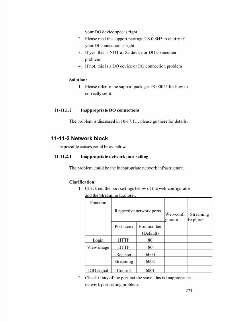
8/21/2019 IP Surveillance TroubleShooting Guide_V0.9
http://slidepdf.com/reader/full/ip-surveillance-troubleshooting-guidev09 276/347
274
your DO device spec is right.
2. Please read the support package TS-00045 to clarify if
your DI connection is right.
3. If yes, this is NOT a DO device or DO connection
problem.
4. If not, this is a DO device or DO connection problem
Solution:
1. Please refer to the support package TS-00045 for how to
correctly set it.
11-11.1.2 Inappropriate DO connections
The problem is discussed in 10-17.1.1, please go there for details.
11-11-2 Network block
The possible causes could be as below.
11-11.2.1 Inappropriate network port setting
The problem could be the inappropriate network infrastructure.
Clarification:
1. Check out the port settings below of the web-configurator
and the Streaming Explorer.
Respective network ports
Function
Port name Port number
(Default)
Web-confi
gurator
Streaming
Explorer
Login HTTP 80
HTTP 80
Register 6000
View image
Streaming 6002
DIO signal Control 6001
2. Check if any of the port not the same, this is Inappropriate
network port setting problem.
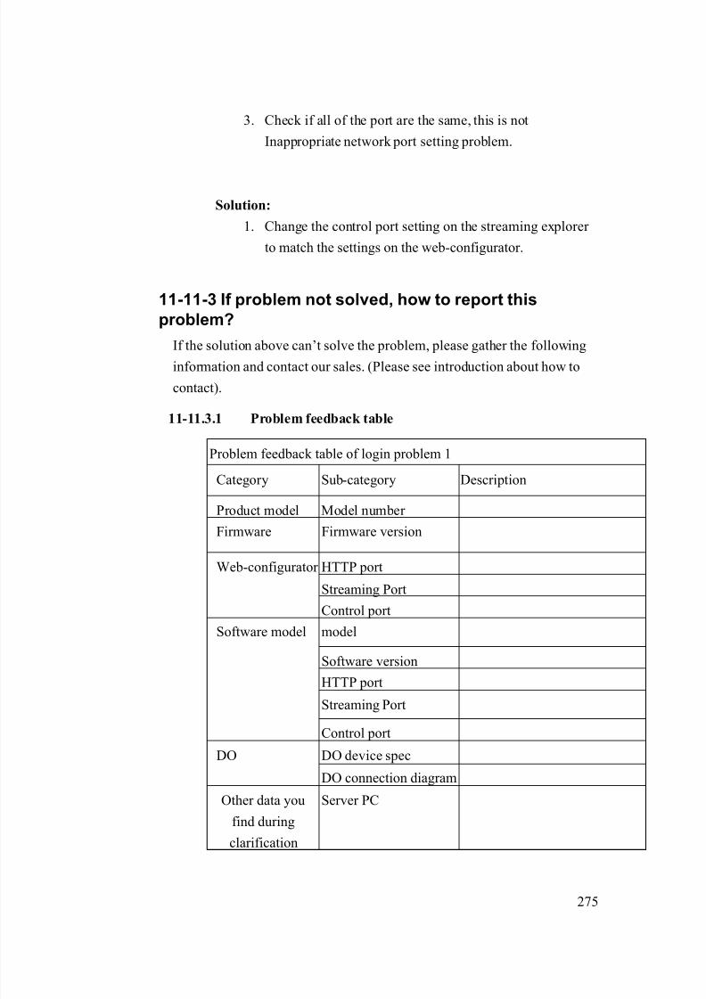
8/21/2019 IP Surveillance TroubleShooting Guide_V0.9
http://slidepdf.com/reader/full/ip-surveillance-troubleshooting-guidev09 277/347
275
3. Check if all of the port are the same, this is not
Inappropriate network port setting problem.
Solution:
1. Change the control port setting on the streaming explorer
to match the settings on the web-configurator.
11-11-3 If problem not solved, how to report this
problem?
If the solution above can’t solve the problem, please gather the followinginformation and contact our sales. (Please see introduction about how to
contact).
11-11.3.1 Problem feedback table
Problem feedback table of login problem 1
Category Sub-category Description
Product model Model number
Firmware Firmware version
HTTP port
Streaming Port
Web-configurator
Control port
model
Software version
HTTP port
Streaming Port
Software model
Control port
DO device specDO
DO connection diagram
Other data you
find during
clarification
Server PC

8/21/2019 IP Surveillance TroubleShooting Guide_V0.9
http://slidepdf.com/reader/full/ip-surveillance-troubleshooting-guidev09 278/347
276
11-12 MD Problem Type 11
Refer to the cause clarification and respective solutions of each problem
type below. RED circled parts below indicating which building block mightcause this problem.
11-12-1 Network block
The possible causes could be as below.
11-12.1.1 Inappropriate network infrastructure (if you were
connecting via LAN)
The problem could be the inappropriate network infrastructure.
Clarification:
1. Below is the status of this problem definition so far.
Network
Management
Storage
maging
Monitor
Management

8/21/2019 IP Surveillance TroubleShooting Guide_V0.9
http://slidepdf.com/reader/full/ip-surveillance-troubleshooting-guidev09 279/347
277
Network
environment Respective network ports
Function
Cross-over LAN Port name Port number (Default)
Login Yes Yes HTTP 80
HTTP 80
Register 6000
View image Yes Yes
Streaming 6002
DIO signal Yes No Control 6001
2. As you can see from the table, there’s something wrong
about your LAN.
Solution:
1. Because this problem involves mostly about your LAN
environment, it’s less possible for us to provide the
solution.
2. Please fill in your definition table
Network environment Respective network ports
Function
Cross-over LAN Port name Port number
Login Yes Yes HTTP
HTTP
Register
View image Yes Yes
Streaming
DIO signal Yes No Control
3. Please provide the definition table above to your MIS or
your network architect for this problem. Ask him for
solution.

8/21/2019 IP Surveillance TroubleShooting Guide_V0.9
http://slidepdf.com/reader/full/ip-surveillance-troubleshooting-guidev09 280/347
278
11-12.1.2 Inappropriate network port forwarding (if you wereconnecting via WAN)
The problem could be the inappropriate network transmission.
Network transmission involves correct setting below. Then we put
them all together.
Network transmission check table
Category Sub-category
Internet connectivityVideo Server
Port setting
Port forwarding Network
Firewall setting
PC Internet connectivity
Clarification:
1. Below is the status of this problem definition so far.
Network environment
Respective network ports
Function
Cross-over WAN Port name Port number
(Default)
Login Yes Yes HTTP 80
HTTP 80
Register 6000
Monitor Yes Yes
Streaming 6002
MD signal Yes No Control 6001
2. As you can see from the table, there’s something wrongabout your WAN.
3. Please read the support package TS-00009 attached.
- Chapter 1~3: How does internet communication works
- Appendix C : How to check the network
communication for Monitoring images
4. If the check fails, this is a network communication
problem.

8/21/2019 IP Surveillance TroubleShooting Guide_V0.9
http://slidepdf.com/reader/full/ip-surveillance-troubleshooting-guidev09 281/347
279
5. If the check ok, this is not a network communication
problem.
Solution:
1. Follows the support package TS-00009 to build up the
internet communication step by step. .
11-12.1.3 Blocked by firewall (if you were connecting via WAN)
The problem is discussed in 10-11.1.2, please go there for details.
11-12.1.4 DNS problem (if you were connecting via DNS)
This problem could happen if you connect to the video server/IP
camera using Domain Name (Ex: http://myroom.dyndns.org)
instead of IP address (Ex: http://59.233.23.59).
Clarification:
1. Please switch the software setting from IP address from
Domain Name to IP address and see if you can monitor
the images.
2. If yes, this is a DNS problem.
3. If not, this is not a DNS problem.
Solution:
1. Report the following information to our sales. We will
provide you an updated version A.S.A.P.
Category Description Example:
HardwareModel number
SED-2120
Firmware
version
A1D-V2.00.00
Software model NVR
Software
version
V1.00.00
2. Before you get that updated version, you can use IP

8/21/2019 IP Surveillance TroubleShooting Guide_V0.9
http://slidepdf.com/reader/full/ip-surveillance-troubleshooting-guidev09 282/347
280
address instead of Domain name to connect to the video
server/IP camera an a contingency plan.
11-12-2 Management block
The possible causes could be as below.
11-12.2.1 Inappropriate Streaming Activator – event setting
This problem could happen if you didn’t setup the event setting in
the Streaming Activator right.
Clarification:1. Please read the Streaming Activator’s software manual for
how to setup the event setting.
2. Clarify if your settings are right.
3. If yes, this is NOT an inappropriate Streaming Activator –
event setting
4. If not, this is an inappropriate Streaming Activator – event
client setting.
Solution:
1. Please refer to the Streaming Activator’s software manual
for how to correctly set it.
11-12-3 If problem not solved, how to report thisproblem?
If the solution above can’t solve the problem, please gather the following
information and contact our sales. (Please see introduction about how to
contact).
11-12.3.1 Problem feedback table
Problem feedback table of login problem 1
Category Sub-category Description
Product model Model number
Firmware Firmware version
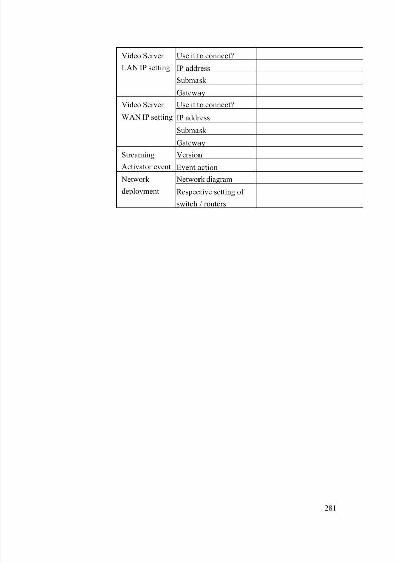
8/21/2019 IP Surveillance TroubleShooting Guide_V0.9
http://slidepdf.com/reader/full/ip-surveillance-troubleshooting-guidev09 283/347
281
Use it to connect?
IP address
Submask
Video Server
LAN IP setting
Gateway
Use it to connect?
IP address
Submask
Video Server
WAN IP setting
Gateway
VersionStreaming
Activator event Event action
Network diagram Network
deployment Respective setting of
switch / routers.

8/21/2019 IP Surveillance TroubleShooting Guide_V0.9
http://slidepdf.com/reader/full/ip-surveillance-troubleshooting-guidev09 284/347
282
11-13 MD Problem Type 12
Refer to the cause clarification and respective solutions of each problem
type below. RED circled parts below indicating which building block mightcause this problem.
11-13-1 Management block
The possible causes could be as below.
11-13.1.1 Inappropriate recording setting
This problem could happen if your recording settings are wrong.
Clarification:
9. Please read the Streaming Activator’s software manual for
how to setup the record setting.
10. Clarify if your settings are right.
Network
Management
Storage
maging
Monitor
Management

8/21/2019 IP Surveillance TroubleShooting Guide_V0.9
http://slidepdf.com/reader/full/ip-surveillance-troubleshooting-guidev09 285/347
283
11. If yes, this is NOT an inappropriate recording – setting.
12. If not, this is an inappropriate recording – setting.
Solution:
3. Please refer to the Streaming Activator’s software
manual for how to correctly set it.
11-13.1.2 Inappropriate PC authority
This problem could happen if your have limited PC authority
which will cause you problem when
a. Executing program
b. Save recordings
Clarification:
7. Please check if you login this PC as “Administrator” or
any account with the same authority.
8. If yes, this is NOT an inappropriate PC authority.
9. If not, this is an inappropriate PC authority.
Solution:3. Always login this PC as “Administrator”.
11-13.1.3 Insufficient HD space
If your HD space is not sufficient, you will have problem recording
files.
Clarification:9. Open Streaming Activator
10. See if there’s HD insufficient warning pop-out right after
you login
11. If not, this is NOT an insufficient HD space.
12. If not, this is an insufficient HD space.
Solution:
5. Your system must have enough HD space for software to
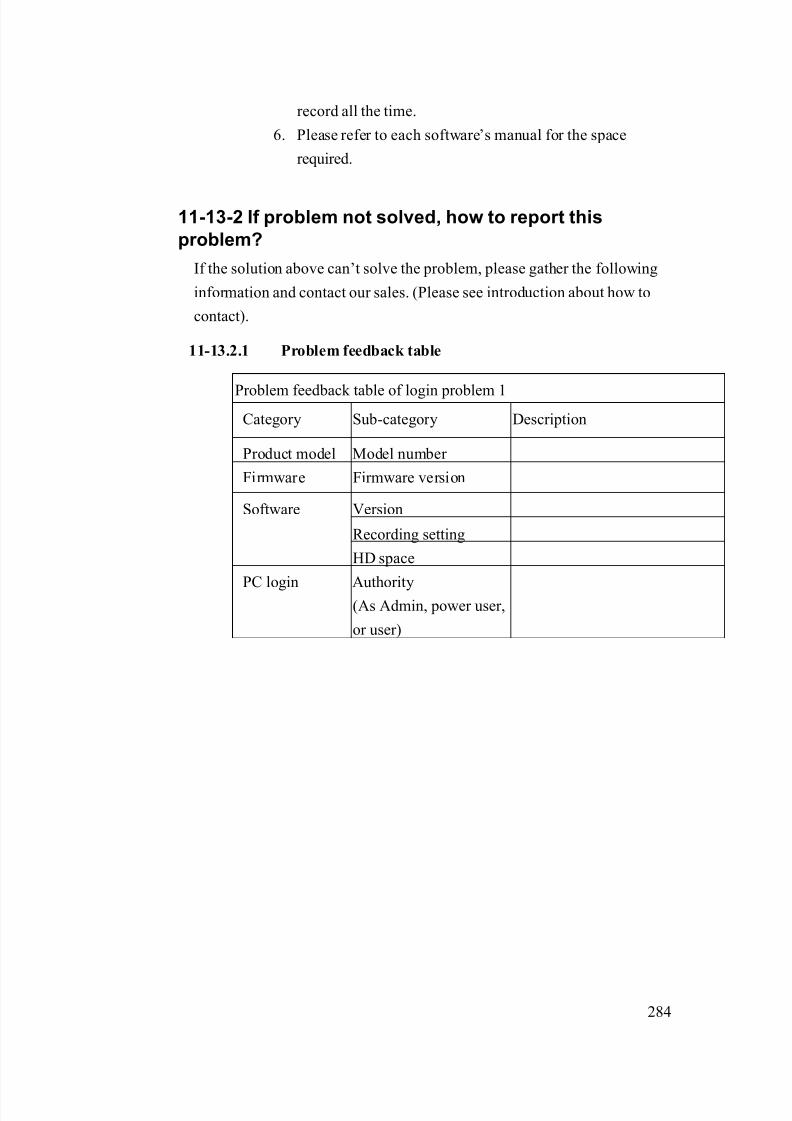
8/21/2019 IP Surveillance TroubleShooting Guide_V0.9
http://slidepdf.com/reader/full/ip-surveillance-troubleshooting-guidev09 286/347
284
record all the time.
6. Please refer to each software’s manual for the space
required.
11-13-2 If problem not solved, how to report this
problem?
If the solution above can’t solve the problem, please gather the following
information and contact our sales. (Please see introduction about how to
contact).
11-13.2.1 Problem feedback table
Problem feedback table of login problem 1
Category Sub-category Description
Product model Model number
Firmware Firmware version
Version
Recording setting
Software
HD space
PC login Authority(As Admin, power user,
or user)
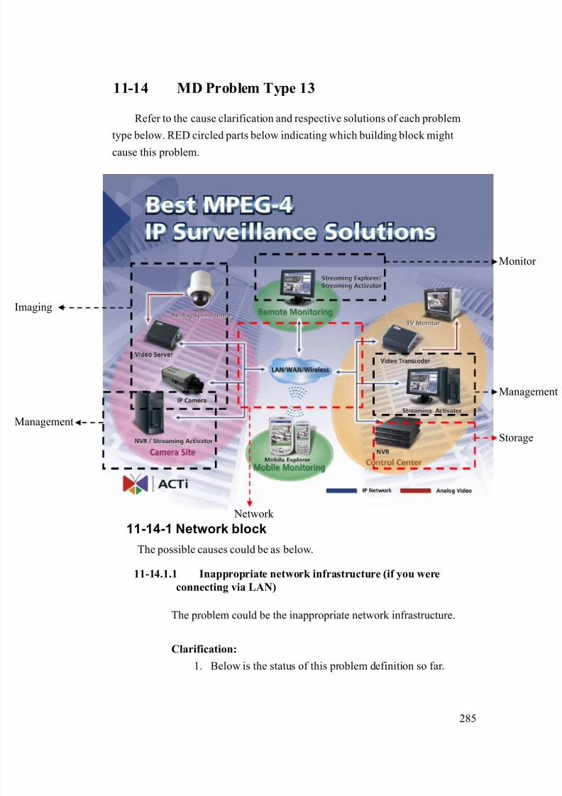
8/21/2019 IP Surveillance TroubleShooting Guide_V0.9
http://slidepdf.com/reader/full/ip-surveillance-troubleshooting-guidev09 287/347
285
11-14 MD Problem Type 13
Refer to the cause clarification and respective solutions of each problem
type below. RED circled parts below indicating which building block mightcause this problem.
11-14-1 Network block
The possible causes could be as below.
11-14.1.1 Inappropriate network infrastructure (if you were
connecting via LAN)
The problem could be the inappropriate network infrastructure.
Clarification:
1. Below is the status of this problem definition so far.
Network
Management
Storage
maging
Monitor
Management

8/21/2019 IP Surveillance TroubleShooting Guide_V0.9
http://slidepdf.com/reader/full/ip-surveillance-troubleshooting-guidev09 288/347
286
Network
environment Respective network ports
Function
Cross-over LAN Port name Port number (Default)
Login Yes Yes HTTP 80
HTTP 80
Register 6000
View image Yes Yes
Streaming 6002
DIO signal Yes No Control 6001
2. As you can see from the table, there’s something wrong
about your LAN.
Solution:
1. Because this problem involves mostly about your LAN
environment, it’s less possible for us to provide the
solution.
2. Please fill in your definition table
Network environment Respective network ports
Function
Cross-over LAN Port name Port number
Login Yes Yes HTTP
HTTP
Register
View image Yes Yes
Streaming
DIO signal Yes No Control
3. Please provide the definition table above to your MIS or
your network architect for this problem. Ask him for
solution.

8/21/2019 IP Surveillance TroubleShooting Guide_V0.9
http://slidepdf.com/reader/full/ip-surveillance-troubleshooting-guidev09 289/347
287
11-14.1.2 Inappropriate network port forwarding (if you wereconnecting via WAN)
The problem could be the inappropriate network transmission.
Network transmission involves correct setting below. Then we put
them all together.
Network transmission check table
Category Sub-category
Internet connectivityVideo Server
Port setting
Port forwarding Network Firewall setting
PC Internet connectivity
Clarification:
1. Below is the status of this problem definition so far.
Network environment
Respective network ports
Function
Cross-over WAN Port name Port number
(Default)
Login Yes Yes HTTP 80
HTTP 80
Register 6000
Monitor Yes Yes
Streaming 6002
MD signal Yes No Control 60012. As you can see from the table, there’s something wrong
about your WAN.
3. Please read the support package TS-00009 attached.
- Chapter 1~3: How does internet communication works
- Appendix C : How to check the network
communication for Monitoring images
4. If the check fails, this is a network communication
problem.

8/21/2019 IP Surveillance TroubleShooting Guide_V0.9
http://slidepdf.com/reader/full/ip-surveillance-troubleshooting-guidev09 290/347
288
5. If the check ok, this is not a network communication
problem.
Solution:
1. Follows the support package TS-00009 to build up the
internet communication step by step. .
11-14.1.3 Blocked by firewall (if you were connecting via WAN)
The problem is discussed in 11-14.1.2, please go there for details.
11-14.1.4 DNS problem (if you were connecting via DNS)
This problem could happen if you connect to the video server/IP
camera using Domain Name (Ex: http://myroom.dyndns.org)
instead of IP address (Ex: http://59.233.23.59).
Clarification:
1. Please switch the software setting from IP address from
Domain Name to IP address and see if you can monitor
the images.
2. If yes, this is a DNS problem.
3. If not, this is not a DNS problem.
Solution:
1. Report the following information to our sales. We will
provide you an updated version A.S.A.P.
Category Description Example:
HardwareModel number
SED-2120
Firmware
version
A1D-V2.00.00
Software model NVR
Software
version
V1.00.00
2. Before you get that updated version, you can use IP
8/21/2019 IP Surveillance TroubleShooting Guide_V0.9
http://slidepdf.com/reader/full/ip-surveillance-troubleshooting-guidev09 291/347
289
address instead of Domain name to connect to the video
server/IP camera an a contingency plan.
11-14-2 Storage block
The possible causes could be as below.
11-14.2.1 Inappropriate NVR – E-mail client setting
This problem could happen if you didn’t setup the E-mail client
setting in the NVR right.
Clarification:1. Please read the NVR’s software manual for how to setup
the E-mail client setting.
2. Clarify if your settings are right.
3. If yes, this is NOT an inappropriate NVR –E-mail setting
4. If not, this is an inappropriate NVR–E-mail client setting.
Solution:
1. Please refer to the NVR software manual for how tocorrectly set it.
11-14.2.2 Inappropriate NVR – event setting
This problem could happen if you didn’t setup the event setting in
the NVR right.
Clarification:
1. Please read the NVRs software manual for how to setup
the event setting.
2. Clarify if your settings are right.
3. If yes, this is NOT an inappropriate NVR – event setting
4. If not, this is an inappropriate NVR – event client setting.
Solution:
1. Please refer to the NVR’s software manual for how to
correctly set it.
8/21/2019 IP Surveillance TroubleShooting Guide_V0.9
http://slidepdf.com/reader/full/ip-surveillance-troubleshooting-guidev09 292/347
290
11-14-3 If problem not solved, how to report this
problem?
If the solution above can’t solve the problem, please gather the following
information and contact our sales. (Please see introduction about how to
contact).
11-14.3.1 Problem feedback table
Problem feedback table of login problem 1
Category Sub-category Description
Product model Model number
Firmware Firmware version
Use it to connect?
IP address
Submask
Video Server
LAN IP setting
Gateway
Use it to connect?
IP address
Submask
Video Server
WAN IP setting
Gateway
Version
E-mail setting
NVR
Event action
Network diagram Network
deployment Respective setting of
switch / routers.

8/21/2019 IP Surveillance TroubleShooting Guide_V0.9
http://slidepdf.com/reader/full/ip-surveillance-troubleshooting-guidev09 293/347
291
11-15 MD Problem Type 14
Refer to the cause clarification and respective solutions of each problem
type below. RED circled parts below indicating which building block mightcause this problem.
11-15-1 Network block
The possible causes could be as below.
11-15.1.1 Inappropriate network infrastructure (if you were
connecting via LAN)
The problem could be the inappropriate network infrastructure.
Clarification:
1. Below is the status of this problem definition so far.
Network
Management
Storage
maging
Monitor
Management

8/21/2019 IP Surveillance TroubleShooting Guide_V0.9
http://slidepdf.com/reader/full/ip-surveillance-troubleshooting-guidev09 294/347
292
Network
environment Respective network ports
Function
Cross-over LAN Port name Port number (Default)
Login Yes Yes HTTP 80
HTTP 80
Register 6000
View image Yes Yes
Streaming 6002
DIO signal Yes No Control 6001
2. As you can see from the table, there’s something wrong
about your LAN.
Solution:
1. Because this problem involves mostly about your LAN
environment, it’s less possible for us to provide the
solution.
2. Please fill in your definition table
Network environment Respective network ports
Function
Cross-over LAN Port name Port number
Login Yes Yes HTTP
HTTP
Register
View image Yes Yes
Streaming
DIO signal Yes No Control
3. Please provide the definition table above to your MIS or
your network architect for this problem. Ask him for
solution.

8/21/2019 IP Surveillance TroubleShooting Guide_V0.9
http://slidepdf.com/reader/full/ip-surveillance-troubleshooting-guidev09 295/347
293
11-15.1.2 Inappropriate network port forwarding (if you wereconnecting via WAN)
The problem could be the inappropriate network transmission.
Network transmission involves correct setting below. Then we put
them all together.
Network transmission check table
Category Sub-category
Internet connectivityVideo Server
Port setting
Port forwarding Network
Firewall setting
PC Internet connectivity
Clarification:
1. Below is the status of this problem definition so far.
Network environment
Respective network ports
Function
Cross-over WAN Port name Port number
(Default)
Login Yes Yes HTTP 80
HTTP 80
Register 6000
Monitor Yes Yes
Streaming 6002
MD signal Yes No Control 6001
2. As you can see from the table, there’s something wrongabout your WAN.
3. Please read the support package TS-00009 attached.
- Chapter 1~3: How does internet communication works
- Appendix C : How to check the network
communication for Monitoring images
4. If the check fails, this is a network communication
problem.

8/21/2019 IP Surveillance TroubleShooting Guide_V0.9
http://slidepdf.com/reader/full/ip-surveillance-troubleshooting-guidev09 296/347
294
5. If the check ok, this is not a network communication
problem.
Solution:
1. Follows the support package TS-00009 to build up the
internet communication step by step. .
11-15.1.3 Blocked by firewall (if you were connecting via WAN)
The problem is discussed in 10-14.1.2, please go there for details.
11-15.1.4 DNS problem (if you were connecting via DNS)
This problem could happen if you connect to the video server/IP
camera using Domain Name (Ex: http://myroom.dyndns.org)
instead of IP address (Ex: http://59.233.23.59).
Clarification:
1. Please switch the software setting from IP address from
Domain Name to IP address and see if you can monitor
the images.
2. If yes, this is a DNS problem.
3. If not, this is not a DNS problem.
Solution:
1. Report the following information to our sales. We will
provide you an updated version A.S.A.P.
Category Description Example:
HardwareModel number
SED-2120
Firmware
version
A1D-V2.00.00
Software model NVR
Software
version
V1.00.00
2. Before you get that updated version, you can use IP

8/21/2019 IP Surveillance TroubleShooting Guide_V0.9
http://slidepdf.com/reader/full/ip-surveillance-troubleshooting-guidev09 297/347
295
address instead of Domain name to connect to the video
server/IP camera an a contingency plan.
11-15-2 Storage block
The possible causes could be as below.
11-15.2.1 Inappropriate NVR – event setting
This problem could happen if you didn’t setup the event setting in
the NVR right.
Clarification:1. Please read the NVR’s software manual for how to setup
the event setting.
2. Clarify if your settings are right.
3. If yes, this is NOT an inappropriate NVR – event setting
4. If not, this is an inappropriate NVR– event client setting.
Solution:
1. Please refer to the NVR’s software manual for how tocorrectly set it.
11-15-3 If problem not solved, how to report thisproblem?
If the solution above can’t solve the problem, please gather the following
information and contact our sales. (Please see introduction about how to
contact).
11-15.3.1 Problem feedback table
Problem feedback table of login problem 1
Category Sub-category Description
Product model Model number
Firmware Firmware version
Use it to connect?Video Server
LAN IP setting IP address

8/21/2019 IP Surveillance TroubleShooting Guide_V0.9
http://slidepdf.com/reader/full/ip-surveillance-troubleshooting-guidev09 298/347
296
Submask
Gateway
Use it to connect?
IP address
Submask
Video Server
WAN IP setting
Gateway
Version NVR event
Event action
Network diagram Network
deployment Respective setting of
switch / routers.
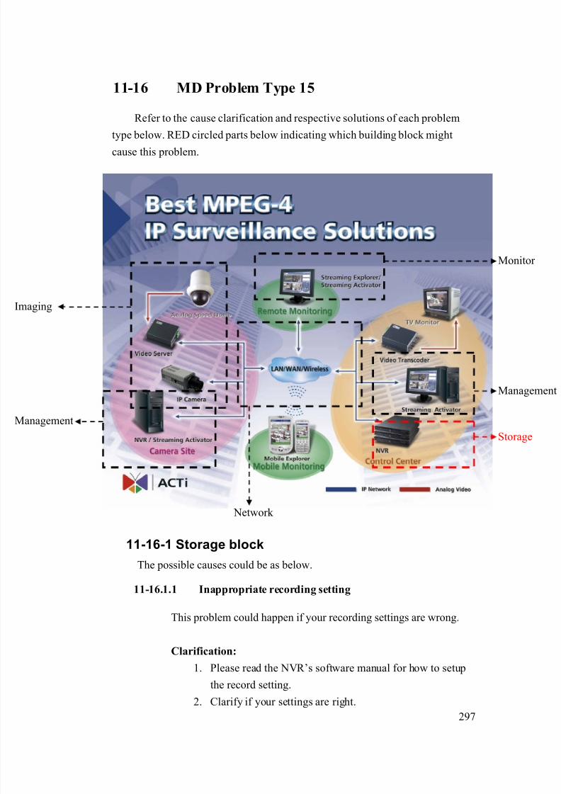
8/21/2019 IP Surveillance TroubleShooting Guide_V0.9
http://slidepdf.com/reader/full/ip-surveillance-troubleshooting-guidev09 299/347
297
11-16 MD Problem Type 15
Refer to the cause clarification and respective solutions of each problem
type below. RED circled parts below indicating which building block mightcause this problem.
11-16-1 Storage block
The possible causes could be as below.
11-16.1.1 Inappropriate recording setting
This problem could happen if your recording settings are wrong.
Clarification:
1. Please read the NVR’s software manual for how to setup
the record setting.
2. Clarify if your settings are right.
Network
Management
Storage
maging
Monitor
Management
8/21/2019 IP Surveillance TroubleShooting Guide_V0.9
http://slidepdf.com/reader/full/ip-surveillance-troubleshooting-guidev09 300/347
298
3. If yes, this is NOT an inappropriate recording – setting.
4. If not, this is an inappropriate recording – setting.
Solution:
1. Please refer to the NVR’s software manual for how to
correctly set it.
11-16.1.2 Inappropriate PC authority
This problem could happen if your have limited PC authority
which will cause you problem when
a. Executing program
b. Save recordings
Clarification:
1. Please check if you login this PC as “Administrator” or
any account with the same authority.
2. If yes, this is NOT an inappropriate PC authority.
3. If not, this is an inappropriate PC authority.
Solution:1. Always login this PC as “Administrator”.
11-16.1.3 Insufficient HD space
If your HD space is not sufficient, you will have problem recording
files.
Clarification:1. Open NVR
2. See if there’s HD insufficient warning pop-out right after
you login
3. If not, this is NOT an insufficient HD space.
4. If not, this is an insufficient HD space.
Solution:
1. Your system must have enough HD space for software to

8/21/2019 IP Surveillance TroubleShooting Guide_V0.9
http://slidepdf.com/reader/full/ip-surveillance-troubleshooting-guidev09 301/347
299
record all the time.
2. Please refer to each software’s manual for the space
required.
11-16-2 If problem not solved, how to report this
problem?
If the solution above can’t solve the problem, please gather the following
information and contact our sales. (Please see introduction about how to
contact).
11-16.2.1 Problem feedback table
Problem feedback table of login problem 1
Category Sub-category Description
Product model Model number
Firmware Firmware version
Version
Recording setting
Software
HD space
PC login Authority(As Admin, power user,
or user)
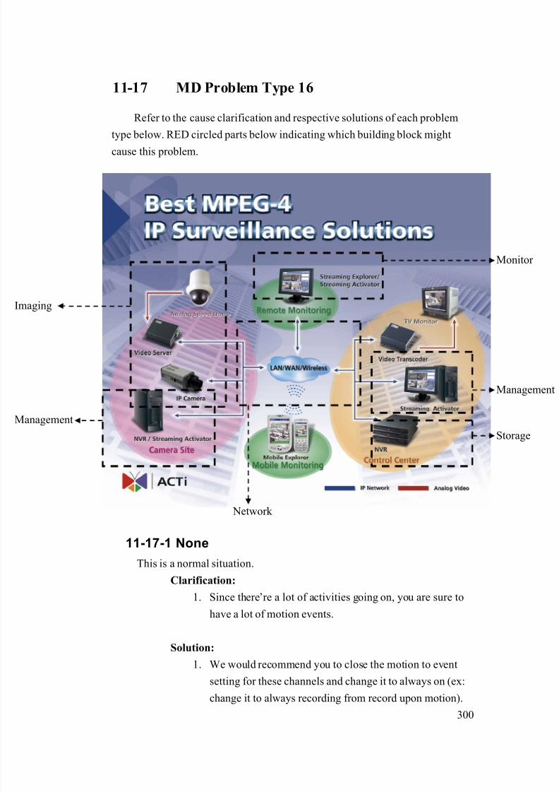
8/21/2019 IP Surveillance TroubleShooting Guide_V0.9
http://slidepdf.com/reader/full/ip-surveillance-troubleshooting-guidev09 302/347
300
11-17 MD Problem Type 16
Refer to the cause clarification and respective solutions of each problem
type below. RED circled parts below indicating which building block mightcause this problem.
11-17-1 None
This is a normal situation.
Clarification:
1. Since there’re a lot of activities going on, you are sure to
have a lot of motion events.
Solution:
1. We would recommend you to close the motion to event
setting for these channels and change it to always on (ex:
change it to always recording from record upon motion).
Network
Management
Storage
maging
Monitor
Management
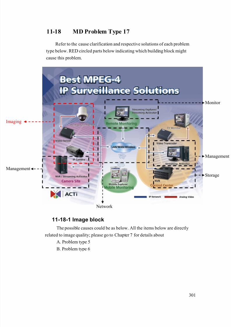
8/21/2019 IP Surveillance TroubleShooting Guide_V0.9
http://slidepdf.com/reader/full/ip-surveillance-troubleshooting-guidev09 303/347
301
11-18 MD Problem Type 17
Refer to the cause clarification and respective solutions of each problem
type below. RED circled parts below indicating which building block might
cause this problem.
11-18-1 Image block
The possible causes could be as below. All the items below are directlyrelated to image quality; please go to Chapter 7 for details about
A. Problem type 5
B. Problem type 6
Network
Management
Storage
maging
Monitor
Management

8/21/2019 IP Surveillance TroubleShooting Guide_V0.9
http://slidepdf.com/reader/full/ip-surveillance-troubleshooting-guidev09 304/347
302
11-19 MD Problem Type 18
Refer to the cause clarification and respective solutions of each problem
type below. RED circled parts below indicating which building block mightcause this problem.
11-19-1 Image block
The possible causes could be as below. All the items below are directly
related to image quality; please go to Chapter 7 for details about
A. Problem type 1
B. Problem type 2
Network
Management
Storage
maging
Monitor
Management
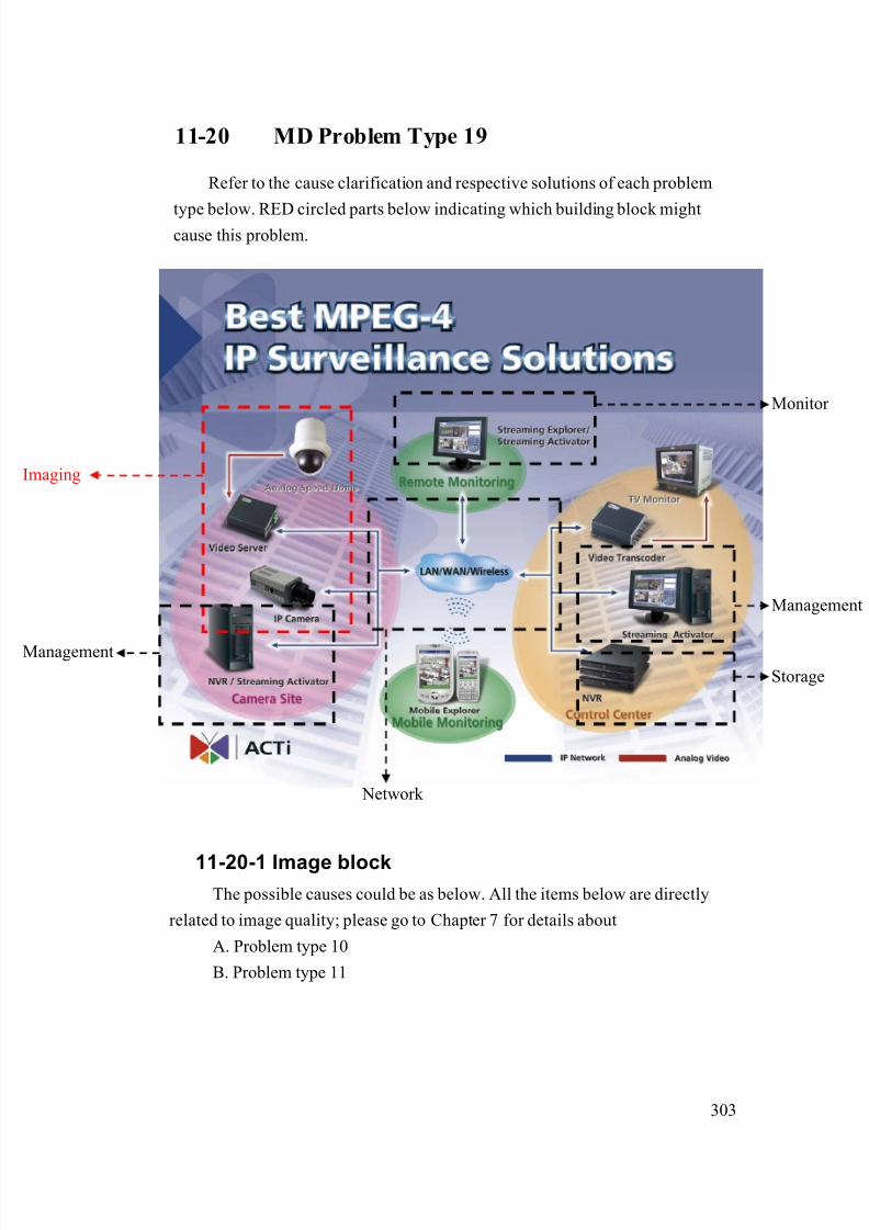
8/21/2019 IP Surveillance TroubleShooting Guide_V0.9
http://slidepdf.com/reader/full/ip-surveillance-troubleshooting-guidev09 305/347
303
11-20 MD Problem Type 19
Refer to the cause clarification and respective solutions of each problem
type below. RED circled parts below indicating which building block mightcause this problem.
11-20-1 Image blockThe possible causes could be as below. All the items below are directly
related to image quality; please go to Chapter 7 for details about
A. Problem type 10
B. Problem type 11
Network
Management
Storage
maging
Monitor
Management

8/21/2019 IP Surveillance TroubleShooting Guide_V0.9
http://slidepdf.com/reader/full/ip-surveillance-troubleshooting-guidev09 306/347
304
11-21 MD Problem Type 20
Refer to the cause clarification and respective solutions of each problem
type below. RED circled parts below indicating which building block mightcause this problem.
11-21-1 Image, Management, storage block
The possible causes could be as below.
11-21.1.1 Inappropriate MD setting – sensitivity
If the sensitivity is too high, it is very likely to trigger false alarm
for tiny little change happen in the scene.
If the sensitivity is too low, it is very likely to ignore everything
happening in the scene.
Network
Management
Storage
maging
Monitor
Management
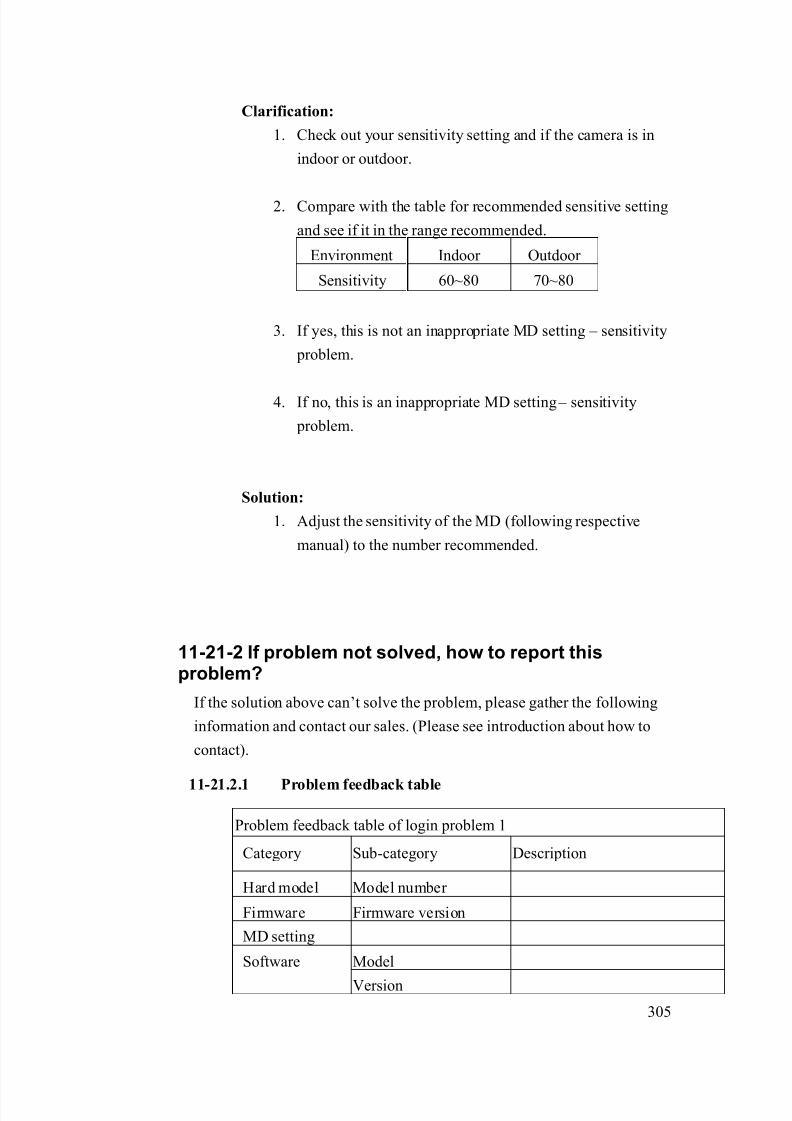
8/21/2019 IP Surveillance TroubleShooting Guide_V0.9
http://slidepdf.com/reader/full/ip-surveillance-troubleshooting-guidev09 307/347
305
Clarification:
1. Check out your sensitivity setting and if the camera is in
indoor or outdoor.
2. Compare with the table for recommended sensitive setting
and see if it in the range recommended.
Environment Indoor Outdoor
Sensitivity 60~80 70~80
3. If yes, this is not an inappropriate MD setting – sensitivity
problem.
4. If no, this is an inappropriate MD setting – sensitivity
problem.
Solution:
1. Adjust the sensitivity of the MD (following respective
manual) to the number recommended.
11-21-2 If problem not solved, how to report thisproblem?
If the solution above can’t solve the problem, please gather the following
information and contact our sales. (Please see introduction about how to
contact).
11-21.2.1 Problem feedback table
Problem feedback table of login problem 1
Category Sub-category Description
Hard model Model number
Firmware Firmware version
MD setting
ModelSoftware
Version

8/21/2019 IP Surveillance TroubleShooting Guide_V0.9
http://slidepdf.com/reader/full/ip-surveillance-troubleshooting-guidev09 308/347
306
MD sensitivity
Other details
you find during
clarification
8/21/2019 IP Surveillance TroubleShooting Guide_V0.9
http://slidepdf.com/reader/full/ip-surveillance-troubleshooting-guidev09 309/347
307
Chapter. 12. Record & Playback ProblemIn this Chapter, we will focus on the problem that you
1. Can login the video server/IP camera
2. Can monitor the image3. You can’t
- record the video
- search and find recorded video
- playback recorded video
We will provide a diagnostic flow for customer to find out his problem type
within this problem category. Then we will examine the possible cause for each
problem type and find out the root cause and respective solutions.
12-1 Find out the possible cause
Please refer to the diagnostic flow to find out the problem type of the Login
Problem.
Then you can refer to next section for advanced clarification and
troubleshooting.
Check Item Remark
Step1 Check the Control Device
Step2 What function do you have problem with?
(Recording)
Can you record manually?
Refer to software
manual
(Search fail)
Can you search while setting search start
time to 1970/01.01 and end time to current
time?
Refer to software
manual
Step3
(Can’t playback)
Can you find the file in the path
Detailed procedure
will be added in
next version
Other advanced clarification related to each problem.Step4
(Recording)
Can you use streaming Activator to
receive DI signal while connection to the
devices via cross-over cable?
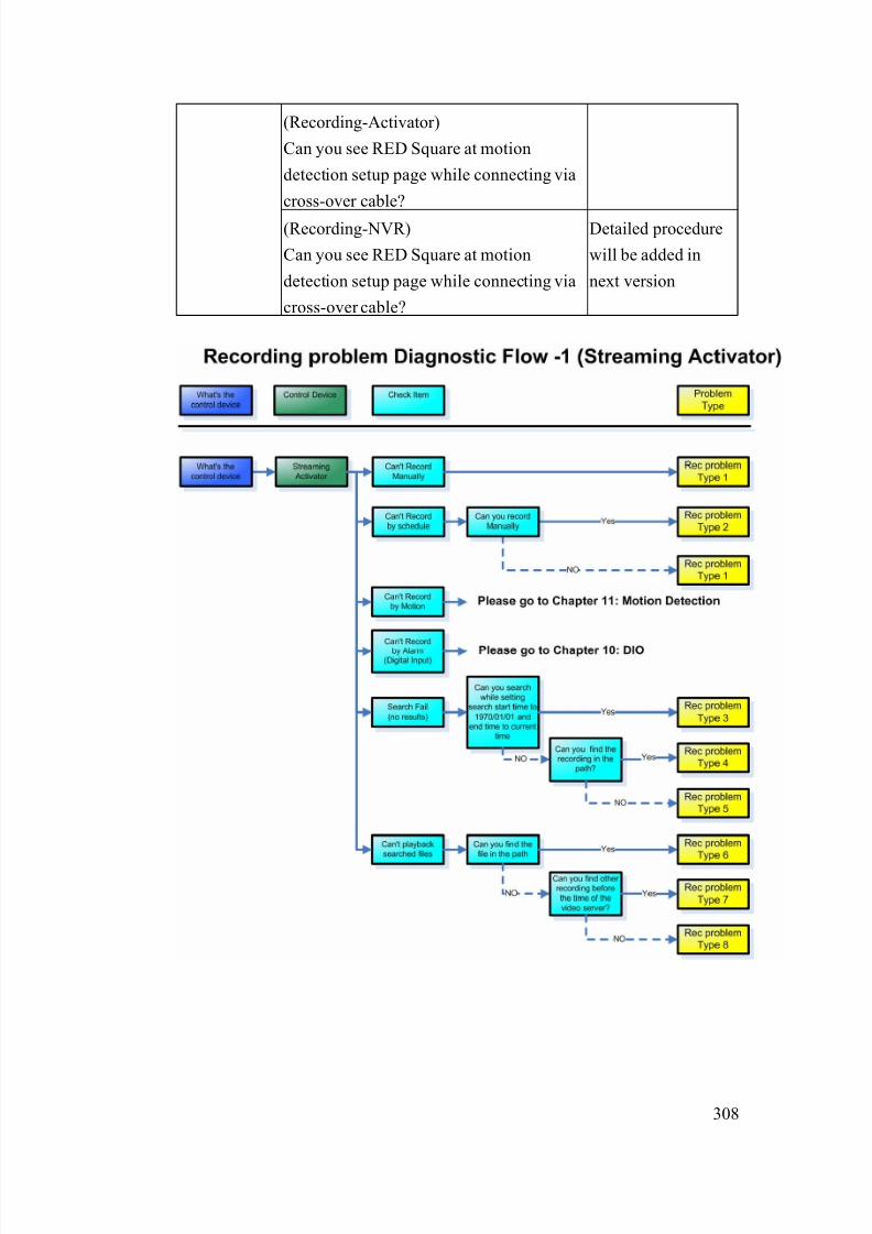
8/21/2019 IP Surveillance TroubleShooting Guide_V0.9
http://slidepdf.com/reader/full/ip-surveillance-troubleshooting-guidev09 310/347
308
(Recording-Activator)
Can you see RED Square at motion
detection setup page while connecting via
cross-over cable?
(Recording-NVR)
Can you see RED Square at motion
detection setup page while connecting via
cross-over cable?
Detailed procedure
will be added in
next version

8/21/2019 IP Surveillance TroubleShooting Guide_V0.9
http://slidepdf.com/reader/full/ip-surveillance-troubleshooting-guidev09 311/347
309
12-2 Record & Playback Problem Type 1
Refer to the cause clarification and respective solutions of each problem
type below. RED circled parts below indicating which building block mightcause this problem.
12-2-1 Management block
The possible causes could be as below.
12-2.1.1 Inappropriate recording setting
This problem could happen if your recording settings are wrong.
Clarification:
13. Please read the Streaming Activator’s software manual for
how to setup the record setting.
14. Clarify if your settings are right.
Network
Management
Storage
maging
Monitor
Management
8/21/2019 IP Surveillance TroubleShooting Guide_V0.9
http://slidepdf.com/reader/full/ip-surveillance-troubleshooting-guidev09 312/347
310
15. If yes, this is NOT an inappropriate recording – setting.
16. If not, this is an inappropriate recording – setting.
Solution:
4. Please refer to the Streaming Activator’s software
manual for how to correctly set it.
12-2.1.2 Inappropriate PC authority
This problem could happen if your have limited PC authority
which will cause you problem when
a. Executing program
b. Save recordings
Clarification:
10. Please check if you login this PC as “Administrator” or
any account with the same authority.
11. If yes, this is NOT an inappropriate PC authority.
12. If not, this is an inappropriate PC authority.
Solution:4. Always login this PC as “Administrator”.
12-2.1.3 Insufficient HD space
If your HD space is not sufficient, you will have problem recording
files.
Clarification:13. Open Streaming Activator
14. See if there’s HD insufficient warning pop-out right after
you login
15. If not, this is NOT an insufficient HD space.
16. If not, this is an insufficient HD space.
Solution:
7. Your system must have enough HD space for software to
8/21/2019 IP Surveillance TroubleShooting Guide_V0.9
http://slidepdf.com/reader/full/ip-surveillance-troubleshooting-guidev09 313/347
311
record all the time.
8. Please refer to each software’s manual for the space
required.
12-2-2 If problem not solved, how to report this
problem?
If the solution above can’t solve the problem, please gather the following
information and contact our sales. (Please see introduction about how to
contact).
12-2.2.1 Problem feedback table
Problem feedback table of login problem 1
Category Sub-category Description
Product model Model number
Firmware Firmware version
Version
Recording setting
Software
HD space
PC login Authority(As Admin, power user,
or user)
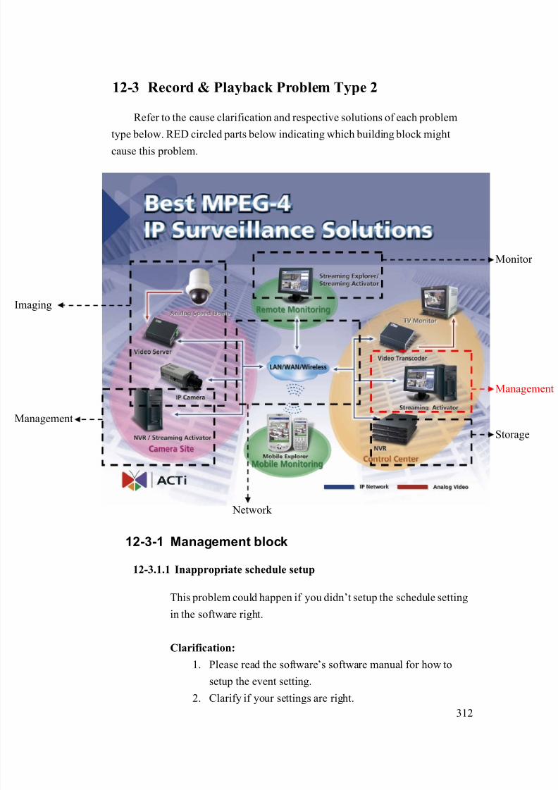
8/21/2019 IP Surveillance TroubleShooting Guide_V0.9
http://slidepdf.com/reader/full/ip-surveillance-troubleshooting-guidev09 314/347
312
12-3 Record & Playback Problem Type 2
Refer to the cause clarification and respective solutions of each problem
type below. RED circled parts below indicating which building block mightcause this problem.
12-3-1 Management block
12-3.1.1 Inappropriate schedule setup
This problem could happen if you didn’t setup the schedule setting
in the software right.
Clarification:
1. Please read the software’s software manual for how to
setup the event setting.
2. Clarify if your settings are right.
Network
Management
Storage
maging
Monitor
Management
8/21/2019 IP Surveillance TroubleShooting Guide_V0.9
http://slidepdf.com/reader/full/ip-surveillance-troubleshooting-guidev09 315/347
313
3. If yes, this is NOT an inappropriate schedule setting
4. If not, this is an inappropriate schedule setting.
Solution:
1. Please refer to the software manual for how to correctly
set it.
12-3-2 If problem not solved, how to report this
problem?
If the solution above can’t solve the problem, please gather the following
information and contact our sales. (Please see introduction about how tocontact).
12-3.2.1 Problem feedback table
Problem feedback table of login problem 1
Category Sub-category Description
Product model Model number
Version
Schedule setting
Software
MDB file
(Software database)
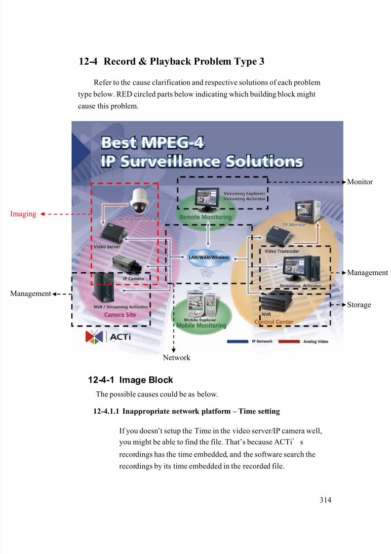
8/21/2019 IP Surveillance TroubleShooting Guide_V0.9
http://slidepdf.com/reader/full/ip-surveillance-troubleshooting-guidev09 316/347
314
12-4 Record & Playback Problem Type 3
Refer to the cause clarification and respective solutions of each problem
type below. RED circled parts below indicating which building block mightcause this problem.
12-4-1 Image Block
The possible causes could be as below.
12-4.1.1 Inappropriate network platform – Time setting
If you doesn’t setup the Time in the video server/IP camera well,
you might be able to find the file. That’s because ACTi’s
recordings has the time embedded, and the software search the
recordings by its time embedded in the recorded file.
Network
Management
Storage
maging
Monitor
Management

8/21/2019 IP Surveillance TroubleShooting Guide_V0.9
http://slidepdf.com/reader/full/ip-surveillance-troubleshooting-guidev09 317/347
315
Clarification:
1. This is clear that your time of the video setting is wrong as
you can see from the search result. .
Solution:
1. Please refer to the firmware manual of the video server/IP
camera for how to set it up.
12-4-2 If problem not solved, how to report this
problem?
If the solution above can’t solve the problem, please gather the following
information and contact our sales. (Please see introduction about how tocontact).
12-4.2.1 Problem feedback table
Problem feedback table of login problem 1
Category Sub-category Description
Product model Model number
Firmware Firmware version
NTP?
Manual
Video Server
Time setting
Time zone
Other things you
find during
clarification
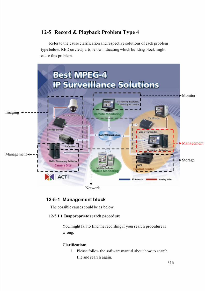
8/21/2019 IP Surveillance TroubleShooting Guide_V0.9
http://slidepdf.com/reader/full/ip-surveillance-troubleshooting-guidev09 318/347
316
12-5 Record & Playback Problem Type 4
Refer to the cause clarification and respective solutions of each problem
type below. RED circled parts below indicating which building block mightcause this problem.
12-5-1 Management block
The possible causes could be as below.
12-5.1.1 Inappropriate search procedure
You might fail to find the recording if your search procedure is
wrong.
Clarification:
1. Please follow the software manual about how to search
file and search again.
Network
Management
Storage
maging
Monitor
Management
8/21/2019 IP Surveillance TroubleShooting Guide_V0.9
http://slidepdf.com/reader/full/ip-surveillance-troubleshooting-guidev09 319/347
317
2. If it solves the problem, this is an inappropriate search
procedure problem.
3. If it doesn’t solve the problem, this is not an inappropriate
search procedure problem.
Solution:
1. Please follow the search procedure in the software manual.
12-5.1.2 Inappropriate database
If the software database is damaged, it might cause your search to
fail but the recordings is ok at the same time.
Clarification:
1. This problem is very hard to clarify. Please send us the
a. software database and
b. information about the recording you wish to find.
Solution:
1. If the problem is truly database issue. It is not reversible.
Be sure to backup the database for time to time and
especially when you upgrade or re-install the software.
12-5-2 If problem not solved, how to report thisproblem?
If the solution above can’t solve the problem, please gather the following
information and contact our sales. (Please see introduction about how to
contact).
1. Problem feedback table
Problem feedback table of login problem 1
Category Sub-category Description
Product model Model number

8/21/2019 IP Surveillance TroubleShooting Guide_V0.9
http://slidepdf.com/reader/full/ip-surveillance-troubleshooting-guidev09 320/347
318
Version
Schedule setting
MDB file
(Software database)
Software
Information about the
recording you wish to
find
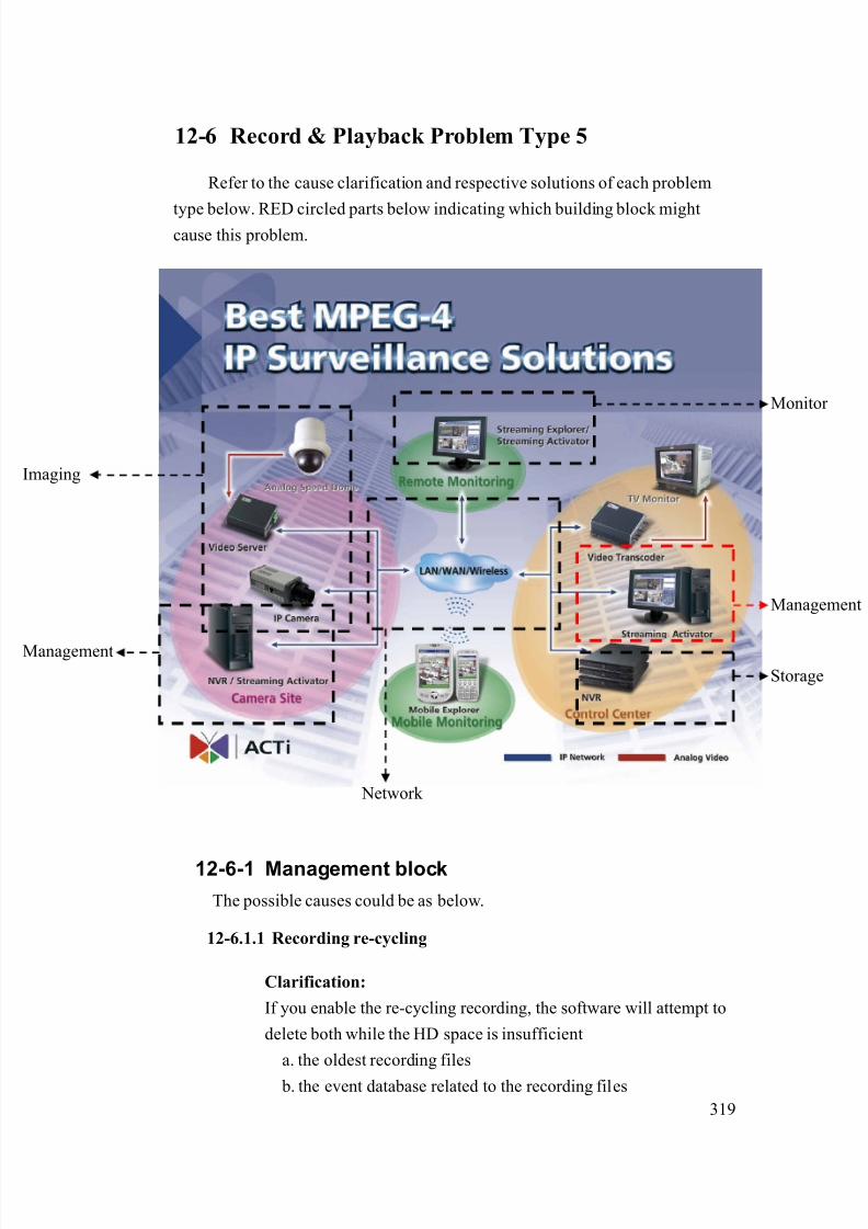
8/21/2019 IP Surveillance TroubleShooting Guide_V0.9
http://slidepdf.com/reader/full/ip-surveillance-troubleshooting-guidev09 321/347
319
12-6 Record & Playback Problem Type 5
Refer to the cause clarification and respective solutions of each problem
type below. RED circled parts below indicating which building block mightcause this problem.
12-6-1 Management block
The possible causes could be as below.
12-6.1.1 Recording re-cycling
Clarification:
If you enable the re-cycling recording, the software will attempt to
delete both while the HD space is insufficient
a. the oldest recording files
b. the event database related to the recording files
Network
Management
Storage
maging
Monitor
Management
8/21/2019 IP Surveillance TroubleShooting Guide_V0.9
http://slidepdf.com/reader/full/ip-surveillance-troubleshooting-guidev09 322/347
320
Then it will cause you not be able to
a. search through software
b. search through recording folder
Solution:
1. Please read the software manual to find the best
a. Software setting
b. Hardware requirement
for you to keep recordings for your desired time
12-6-2 If problem not solved, how to report this
problem?
If the solution above can’t solve the problem, please gather the following
information and contact our sales. (Please see introduction about how to
contact).
2. Problem feedback table
Problem feedback table of login problem 1
Category Sub-category Description
Product model Model number
Version
Schedule setting
MDB file
(Software database)
Software
Information about the
recording you wish to
find
HD HD space
Recording keep
time

8/21/2019 IP Surveillance TroubleShooting Guide_V0.9
http://slidepdf.com/reader/full/ip-surveillance-troubleshooting-guidev09 323/347
321
12-7 Record & Playback Problem Type 6
Refer to the cause clarification and respective solutions of each problem
type below. RED circled parts below indicating which building block might
cause this problem.
12-7-1 Management block
12-7.1.1 Codec missing
If the codec is not installed correctly, you might not be able to
playback the files.
Clarification:
1. Install the codec of FFDshow provided in the product CD
2. Check if you can playback the recording now.
Network
Management
Storage
maging
Monitor
Management

8/21/2019 IP Surveillance TroubleShooting Guide_V0.9
http://slidepdf.com/reader/full/ip-surveillance-troubleshooting-guidev09 324/347
322
3. If yes, this is a codec missing problem.
4. If not, this is not a codec missing problem.
Solution:
1. Make sure the codec is installed properly before you
playback the file.
12-7-2 If problem not solved, how to report this
problem?
If the solution above can’t solve the problem, please gather the following
information and contact our sales. (Please see introduction about how tocontact).
3. Problem feedback table
Problem feedback table of login problem 1
Category Sub-category Description
Product model Model number
VersionSoftware
The recording file you
wish to playback

8/21/2019 IP Surveillance TroubleShooting Guide_V0.9
http://slidepdf.com/reader/full/ip-surveillance-troubleshooting-guidev09 325/347
323
12-8 Record & Playback Problem Type 7
Refer to the cause clarification and respective solutions of each problem
type below. RED circled parts below indicating which building block mightcause this problem.
12-8-1 Management block
12-8.1.1 Unauthorized delete or rename the recording file
Clarification:
1. This problem happens only when someone
a. deletes the file name
b. rename the previous recording file
Solution:
1. Make sure the unauthorized entry and operation of the PC.
Network
Management
Storage
maging
Monitor
Management
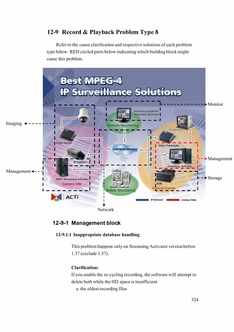
8/21/2019 IP Surveillance TroubleShooting Guide_V0.9
http://slidepdf.com/reader/full/ip-surveillance-troubleshooting-guidev09 326/347
324
12-9 Record & Playback Problem Type 8
Refer to the cause clarification and respective solutions of each problem
type below. RED circled parts below indicating which building block might
cause this problem.
12-9-1 Management block
12-9.1.1 Inappropriate database handling
This problem happens only on Streaming Activator version before
1.37 (exclude 1.37).
Clarification:
If you enable the re-cycling recording, the software will attempt to
delete both while the HD space is insufficient
a. the oldest recording files
Network
Management
Storage
maging
Monitor
Management

8/21/2019 IP Surveillance TroubleShooting Guide_V0.9
http://slidepdf.com/reader/full/ip-surveillance-troubleshooting-guidev09 327/347
325
b. the event database related to the recording files
This problem happens when the software
a. delete the oldest recording
b. keep the event database related to the recording files
Only on Streaming Activator with version 1.36.xx and before has
this problem
Solution:
1. Please upgrade your Streaming Activator version to 1.37
and above.

8/21/2019 IP Surveillance TroubleShooting Guide_V0.9
http://slidepdf.com/reader/full/ip-surveillance-troubleshooting-guidev09 328/347
326
12-10 Record & Playback Problem Type 9
Refer to the cause clarification and respective solutions of each problem
type below. RED circled parts below indicating which building block mightcause this problem.
12-10-1 Storage block
12-10-2 Management block
The possible causes could be as below.
12-10.2.1 Inappropriate recording setting
This problem could happen if your recording settings are wrong.
Clarification:
1. Please read the NVR’s software manual for how to setup
Network
Management
Storage
maging
Monitor
Management
8/21/2019 IP Surveillance TroubleShooting Guide_V0.9
http://slidepdf.com/reader/full/ip-surveillance-troubleshooting-guidev09 329/347
327
the record setting.
2. Clarify if your settings are right.
3. If yes, this is NOT an inappropriate recording – setting.
4. If not, this is an inappropriate recording – setting.
Solution:
1. Please refer to the NVR’s software manual for how to
correctly set it.
12-10.2.2 Inappropriate PC authority
This problem could happen if your have limited PC authority
which will cause you problem when
a. Executing program
b. Save recordings
Clarification:
1. Please check if you login this PC as “Administrator” or
any account with the same authority.
2. If yes, this is NOT an inappropriate PC authority.
3. If not, this is an inappropriate PC authority.
Solution:
1. Always login this PC as “Administrator”.
12-10.2.3 Insufficient HD space
If your HD space is not sufficient, you will have problem recording
files.
Clarification:
1. Open Streaming Activator
2. See if there’s HD insufficient warning pop-out right after
you login
3. If not, this is NOT an insufficient HD space.
4. If not, this is an insufficient HD space.
8/21/2019 IP Surveillance TroubleShooting Guide_V0.9
http://slidepdf.com/reader/full/ip-surveillance-troubleshooting-guidev09 330/347
328
Solution:
1. Your system must have enough HD space for software to
record all the time.
2. Please refer to each software’s manual for the space
required.
12-10-3 If problem not solved, how to report this
problem?
If the solution above can’t solve the problem, please gather the following
information and contact our sales. (Please see introduction about how to
contact).
12-10.3.1 Problem feedback table
Problem feedback table of login problem 1
Category Sub-category Description
Product model Model number
Firmware Firmware version
Version
Recording setting
Software
HD space
PC login Authority
(As Admin, power user,
or user)
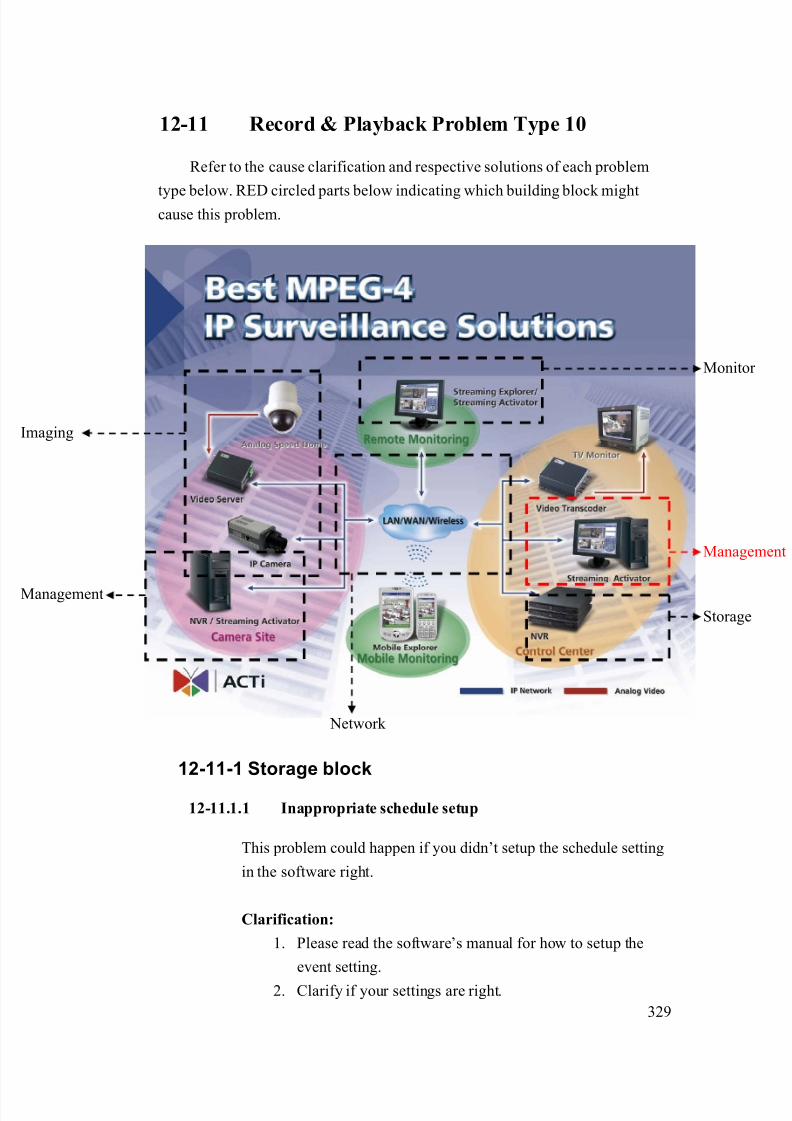
8/21/2019 IP Surveillance TroubleShooting Guide_V0.9
http://slidepdf.com/reader/full/ip-surveillance-troubleshooting-guidev09 331/347
329
12-11 Record & Playback Problem Type 10
Refer to the cause clarification and respective solutions of each problem
type below. RED circled parts below indicating which building block mightcause this problem.
12-11-1 Storage block
12-11.1.1 Inappropriate schedule setup
This problem could happen if you didn’t setup the schedule setting
in the software right.
Clarification:
1. Please read the software’s manual for how to setup the
event setting.
2. Clarify if your settings are right.
Network
Management
Storage
maging
Monitor
Management

8/21/2019 IP Surveillance TroubleShooting Guide_V0.9
http://slidepdf.com/reader/full/ip-surveillance-troubleshooting-guidev09 332/347
330
3. If yes, this is NOT an inappropriate schedule setting
4. If not, this is an inappropriate schedule setting.
Solution:
1. Please refer to the software manual for how to correctly
set it.
12-11-2 If problem not solved, how to report this
problem?
If the solution above can’t solve the problem, please gather the following
information and contact our sales. (Please see introduction about how tocontact).
12-11.2.1 Problem feedback table
Problem feedback table of login problem 1
Category Sub-category Description
Product model Model number
Version
Schedule setting
Software
MDB file
(Software database)
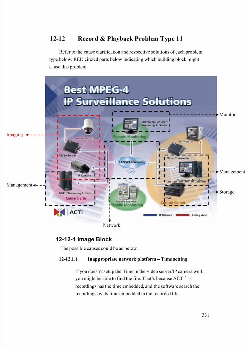
8/21/2019 IP Surveillance TroubleShooting Guide_V0.9
http://slidepdf.com/reader/full/ip-surveillance-troubleshooting-guidev09 333/347
331
12-12 Record & Playback Problem Type 11
Refer to the cause clarification and respective solutions of each problem
type below. RED circled parts below indicating which building block mightcause this problem.
12-12-1 Image Block
The possible causes could be as below.
12-12.1.1 Inappropriate network platform – Time setting
If you doesn’t setup the Time in the video server/IP camera well,
you might be able to find the file. That’s because ACTi’s
recordings has the time embedded, and the software search the
recordings by its time embedded in the recorded file.
Network
Management
Storage
maging
Monitor
Management
8/21/2019 IP Surveillance TroubleShooting Guide_V0.9
http://slidepdf.com/reader/full/ip-surveillance-troubleshooting-guidev09 334/347
332
Clarification:
1. This is clear that your time of the video setting is wrong as
you can see from the search result. .
Solution:
1. Please refer to the firmware manual of the video server/IP
camera for how to set it up.
12-12-2 If problem not solved, how to report this
problem?
If the solution above can’t solve the problem, please gather the following
information and contact our sales. (Please see introduction about how tocontact).
12-12.2.1 Problem feedback table
Problem feedback table of login problem 1
Category Sub-category Description
Product model Model number
Firmware Firmware version
NTP?
Manual
Video Server
Time setting
Time zone
Other things you
find during
clarification

8/21/2019 IP Surveillance TroubleShooting Guide_V0.9
http://slidepdf.com/reader/full/ip-surveillance-troubleshooting-guidev09 335/347
333
12-13 Record & Playback Problem Type 12
Refer to the cause clarification and respective solutions of each problem
type below. RED circled parts below indicating which building block mightcause this problem.
12-13-1 Storage block
The possible causes could be as below.
12-13.1.1 Inappropriate search procedure
You might fail to find the recording if your search procedure is
wrong.
Clarification:
4. Please follow the software manual about how to search
file and search again.
Network
Management
Storage
maging
Monitor
Management
8/21/2019 IP Surveillance TroubleShooting Guide_V0.9
http://slidepdf.com/reader/full/ip-surveillance-troubleshooting-guidev09 336/347
334
5. If it solves the problem, this is an inappropriate search
procedure problem.
6. If it doesn’t solve the problem, this is not an inappropriate
search procedure problem.
Solution:
2. Please follow the search procedure in the software manual.
12-13.1.2 Inappropriate database
If the software database is damaged, it might cause your search to
fail but the recordings is ok at the same time.
Clarification:
2. This problem is very hard to clarify. Please send us the
a. software database and
b. information about the recording you wish to find.
Solution:
2. If the problem is truly database issue. It is not reversible.
Be sure to backup the database for time to time and
especially when you upgrade or re-install the software.
12-13-2 If problem not solved, how to report thisproblem?
If the solution above can’t solve the problem, please gather the following
information and contact our sales. (Please see introduction about how to
contact).
1. Problem feedback table
Problem feedback table of login problem 1
Category Sub-category Description
Product model Model number

8/21/2019 IP Surveillance TroubleShooting Guide_V0.9
http://slidepdf.com/reader/full/ip-surveillance-troubleshooting-guidev09 337/347
335
Version
Schedule setting
MDB file
(Software database)
Software
Information about the
recording you wish to
find

8/21/2019 IP Surveillance TroubleShooting Guide_V0.9
http://slidepdf.com/reader/full/ip-surveillance-troubleshooting-guidev09 338/347
336
12-14 Record & Playback Problem Type 13
Refer to the cause clarification and respective solutions of each problem
type below. RED circled parts below indicating which building block mightcause this problem.
12-14-1 Storage block
12-14.1.1 Recording re-cycling
Clarification:
If you enable the re-cycling recording, the software will attempt to
delete both while the HD space is insufficient
a. the oldest recording files
b. the event database related to the recording files
Then it will cause you not be able to
a. search through software
Network
Management
Storage
maging
Monitor
Management
8/21/2019 IP Surveillance TroubleShooting Guide_V0.9
http://slidepdf.com/reader/full/ip-surveillance-troubleshooting-guidev09 339/347
337
b. search through recording folder
Solution:
1. Please read the software manual to find the best
a. Software setting
b. Hardware requirement
for you to keep recordings for your desired time
12-14-2 If problem not solved, how to report this
problem?
If the solution above can’t solve the problem, please gather the following
information and contact our sales. (Please see introduction about how tocontact).
12-14.2.1 Problem feedback table
Problem feedback table of login problem 1
Category Sub-category Description
Product model Model number
Version
Schedule setting
MDB file
(Software database)
Software
Information about the
recording you wish to
find
HD HD space
Recording keep
time

8/21/2019 IP Surveillance TroubleShooting Guide_V0.9
http://slidepdf.com/reader/full/ip-surveillance-troubleshooting-guidev09 340/347
338
12-15 Record & Playback Problem Type 14
Refer to the cause clarification and respective solutions of each problem
type below. RED circled parts below indicating which building block mightcause this problem.
12-15-1 Storage block
12-15.1.1 Codec missing
If the codec is not installed correctly, you might not be able to
playback the files.
Clarification:
1. Install the codec of FFDshow provided in the product CD
2. Check if you can playback the recording now.
Network
Management
Storage
maging
Monitor
Management

8/21/2019 IP Surveillance TroubleShooting Guide_V0.9
http://slidepdf.com/reader/full/ip-surveillance-troubleshooting-guidev09 341/347
339
3. If yes, this is a codec missing problem.
4. If not, this is not a codec missing problem.
Solution:
1. Make sure the codec is installed properly before you
playback the file.
12-15-2 If problem not solved, how to report this
problem?
If the solution above can’t solve the problem, please gather the following
information and contact our sales. (Please see introduction about how tocontact).
2. Problem feedback table
Problem feedback table of login problem 1
Category Sub-category Description
Product model Model number
VersionSoftware
The recording file you
wish to playback
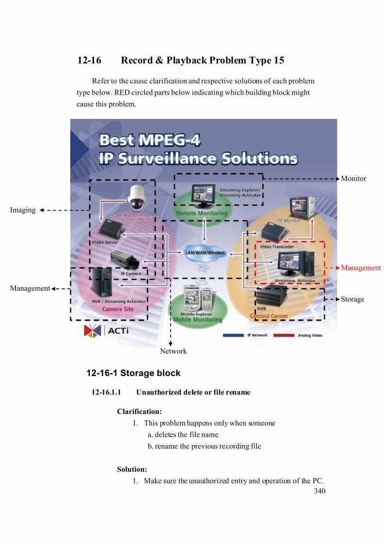
8/21/2019 IP Surveillance TroubleShooting Guide_V0.9
http://slidepdf.com/reader/full/ip-surveillance-troubleshooting-guidev09 342/347
340
12-16 Record & Playback Problem Type 15
Refer to the cause clarification and respective solutions of each problem
type below. RED circled parts below indicating which building block mightcause this problem.
12-16-1 Storage block
12-16.1.1 Unauthorized delete or file rename
Clarification:
1. This problem happens only when someone
a. deletes the file name
b. rename the previous recording file
Solution:
1. Make sure the unauthorized entry and operation of the PC.
Network
Management
Storage
maging
Monitor
Management
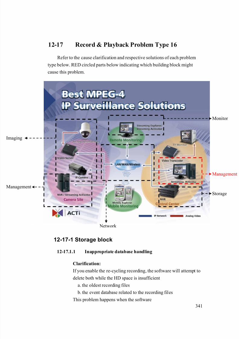
8/21/2019 IP Surveillance TroubleShooting Guide_V0.9
http://slidepdf.com/reader/full/ip-surveillance-troubleshooting-guidev09 343/347
341
12-17 Record & Playback Problem Type 16
Refer to the cause clarification and respective solutions of each problemtype below. RED circled parts below indicating which building block might
cause this problem.
12-17-1 Storage block
12-17.1.1 Inappropriate database handling
Clarification:
If you enable the re-cycling recording, the software will attempt to
delete both while the HD space is insufficient
a. the oldest recording files
b. the event database related to the recording files
This problem happens when the software
Network
Management
Storage
maging
Monitor
Management

8/21/2019 IP Surveillance TroubleShooting Guide_V0.9
http://slidepdf.com/reader/full/ip-surveillance-troubleshooting-guidev09 344/347
342
a. delete the oldest recording
b. keep the event database related to the recording files
Solution:
1. Please provide the feedback table as below and contact our
sales (See introduction about how to contact). We will
give you an solution A.S.A.P.
.
Problem feedback table of login problem 1
Category Sub-category Description
Product model Model number
Version
Your recording setup
Software
Database

8/21/2019 IP Surveillance TroubleShooting Guide_V0.9
http://slidepdf.com/reader/full/ip-surveillance-troubleshooting-guidev09 345/347
343
Chapter. 13. Appendix.
13-1 Appendix. A How to test your latency?
Below is the latency testing procedure for you to find your own latency. You can
then refer this latency figure to our latency figure. Then you know whether you have
the optimized latency performance or not?
13-1-1 A. Get the counter program
13-1.1.1 Download the program
http://www.acti.com/support/Package/TS-00066/counter.zip
13-1.1.2 Unzip the file
A counter.exe appears.
13-1-2 B. Test procedure
13-1.2.1 Execute the counter.exe
A counter window appears.
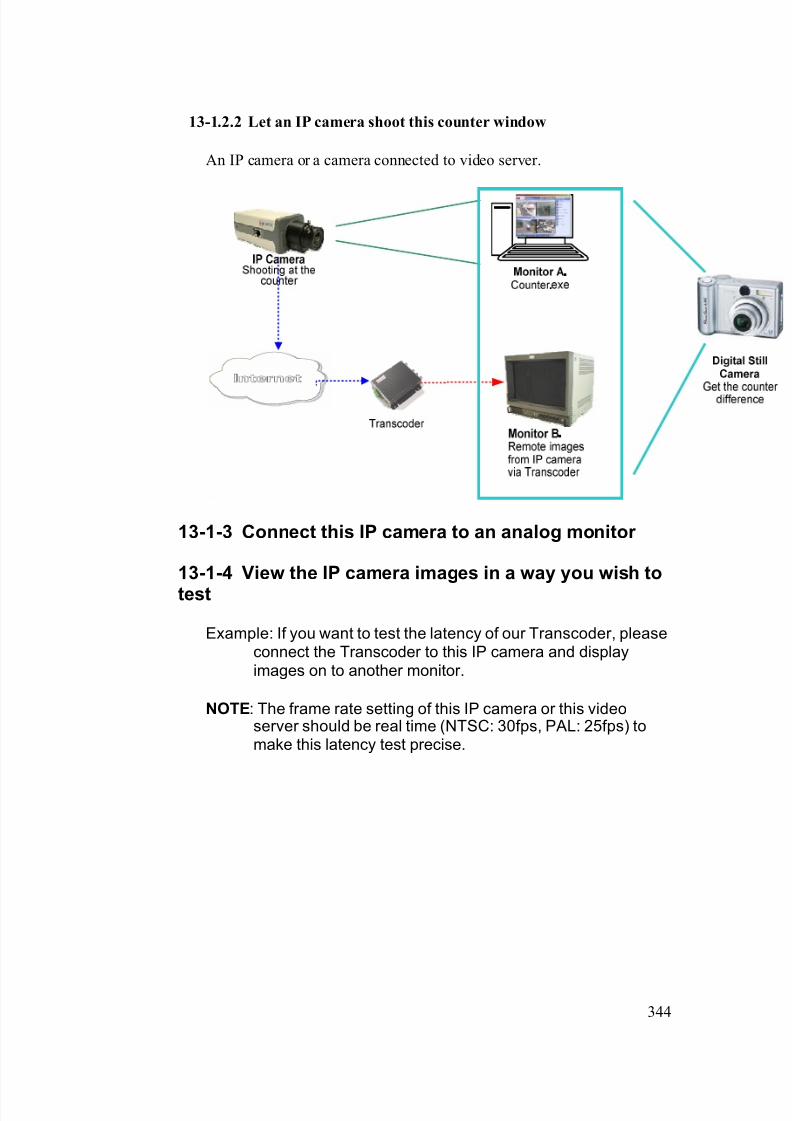
8/21/2019 IP Surveillance TroubleShooting Guide_V0.9
http://slidepdf.com/reader/full/ip-surveillance-troubleshooting-guidev09 346/347
344
13-1.2.2 Let an IP camera shoot this counter window
An IP camera or a camera connected to video server.
13-1-3 Connect this IP camera to an analog monitor
13-1-4 View the IP camera images in a way you wish to
test
Example: If you want to test the latency of our Transcoder, pleaseconnect the Transcoder to this IP camera and displayimages on to another monitor.
NOTE: The frame rate setting of this IP camera or this videoserver should be real time (NTSC: 30fps, PAL: 25fps) tomake this latency test precise.

8/21/2019 IP Surveillance TroubleShooting Guide_V0.9
http://slidepdf.com/reader/full/ip-surveillance-troubleshooting-guidev09 347/347
345
13-1-5 Use Digital Still Camera to capture the Counter
difference between two displays.
13-1-6 Get your latency.
Minus the counter number from monitor A by counter number frommonitor B to get your latency.
Example: As shown in picture, the latency is 10fps. (04:45:13 –04:45:03)
13-1-7 Check if the latency ok
Below is the standard latency result. If your latency is higher thanthat, there is a latency problem.
Protocol TypeLatency
(ms) TCP1.0 TCP2.0
NTSC 330~423 232~297
Monitor B.Images from IP camera via
Transcoder
Monitor A.Original images from counter
window