IP HORN SPEAKER UC- 4SC615 Q
12
INSTALLATION MANUAL IP HORN SPEAKER UC- 4SC615 Q Thank you for purchasing TOA’s IP Horn Speaker. Please carefully follow the instructions in this manual to ensure long, trouble-free use of your equipment.
Transcript of IP HORN SPEAKER UC- 4SC615 Q

INSTALLATION MANUAL
IP HORN SPEAKER UC- 4SC615 Q
Thank you for purchasing TOA’s IP Horn Speaker.Please carefully follow the instructions in this manual to ensure long, trouble-free use of your equipment.

CONTENTS
.................................................................. 3
....................................................................................... 4
....................................................................................... 5
............................................................... 5
...................................................... 6
................................................................................. 7............................................................. 7
........................................................................ 7................................................................ 7
......................................................................... 8........................................................................... 8
............................................................ 8
................................................................................ 9
.......................................... 10
......................................................................... 11
2
1. SAFETY INFORMATION
2. OVERVIEW
3. FEATURES
4. NAMES AND FUNCTIONS
5. INSTALLATION PRECAUTIONS
6. INSTALLATION6.1. How to Use the Cable Gland
6.2. Network Connection
6.3. Terminal Plug Connection
7. SYSTEM SETTINGS7.1. Before You Begin
7.2. Connection to System Setting
8. INITIALIZATION
9. SOFTWARE LICENSE INFORMATION
10. SPECIFICATIONS
1. SAFETY INFORMATIONBefore installation or use, make sure to carefully read all the instructions in this section for correctand safe operation.Make sure to follow all the precautionary instructions in this section, which contain importantwarnings and/or cautions regarding safety.After reading, keep this manual handy for future reference.
Safety Symbol and Message ConventionsSafety symbols and message described below are used in this manual to prevent bodily injury and property damage which could result from mishandling. Before operating your product, read this manual first and understand the safety symbols and messages so you are thoroughly aware of the potential safety hazards.
When Installing the Unit• Install the unit only in a location that can
structurally support the weight of the unit andthe mounting bracket. Doing otherwise mayresult in the unit falling down and causingpersonal injury and/or property damage.
• When installing the unit in the snowy area,take appropriate measures to prevent snowfrom lying on the unit. If the snow lies on theunit, the unit may fall, causing personalinjuries.
• Do not use other methods than specified tomount the bracket. Extreme force is applied tothe unit and the unit could fall off, possiblyresulting in personal injuries.
• Attach the safety wire to the unit. If notattached, the unit could fall off, resulting inpersonal injury.
• Use nuts and bolts that are appropriate for theceiling's or wall's structure and composition.Failure to do so may cause the speaker to fall,resulting in material damage and possiblepersonal injury.
• Tighten each nut and bolt securely. Ensurethat the bracket has no loose joints afterinstallation to prevent accidents that couldresult in personal injury.
• Do not mount the unit in locations exposed toconstant vibration. The mounting bracket canbe damaged by excessive vibration, potentiallycausing the unit to fall, which could result inpersonal injury.
When the Unit is in Use• Should the following irregularity be found
during use, immediately switch off the power,disconnect the power supply plug from the ACoutlet and contact your nearest TOA dealer.Make no further attempt to operate the unit inthis condition as this may cause fire or electricshock.・ If you detect smoke or a strange smell
coming from the unit.・If water or any metallic object gets into the
unit・If the unit falls, or the unit case breaks・If the power supply cord is damaged
(exposure of the core, disconnection, etc.)・If it is malfunctioning (no tone sounds.)
• To prevent a fire or electric shock, never opennor remove the unit case as there are highvoltage components inside the unit. Refer allservicing to qualified service personnel.
• To prevent the electromagnetic wave frombadly influencing medical equipment, makesure to switch off the unit's power whenplacing it in close proximity to the medicalequipment.
3
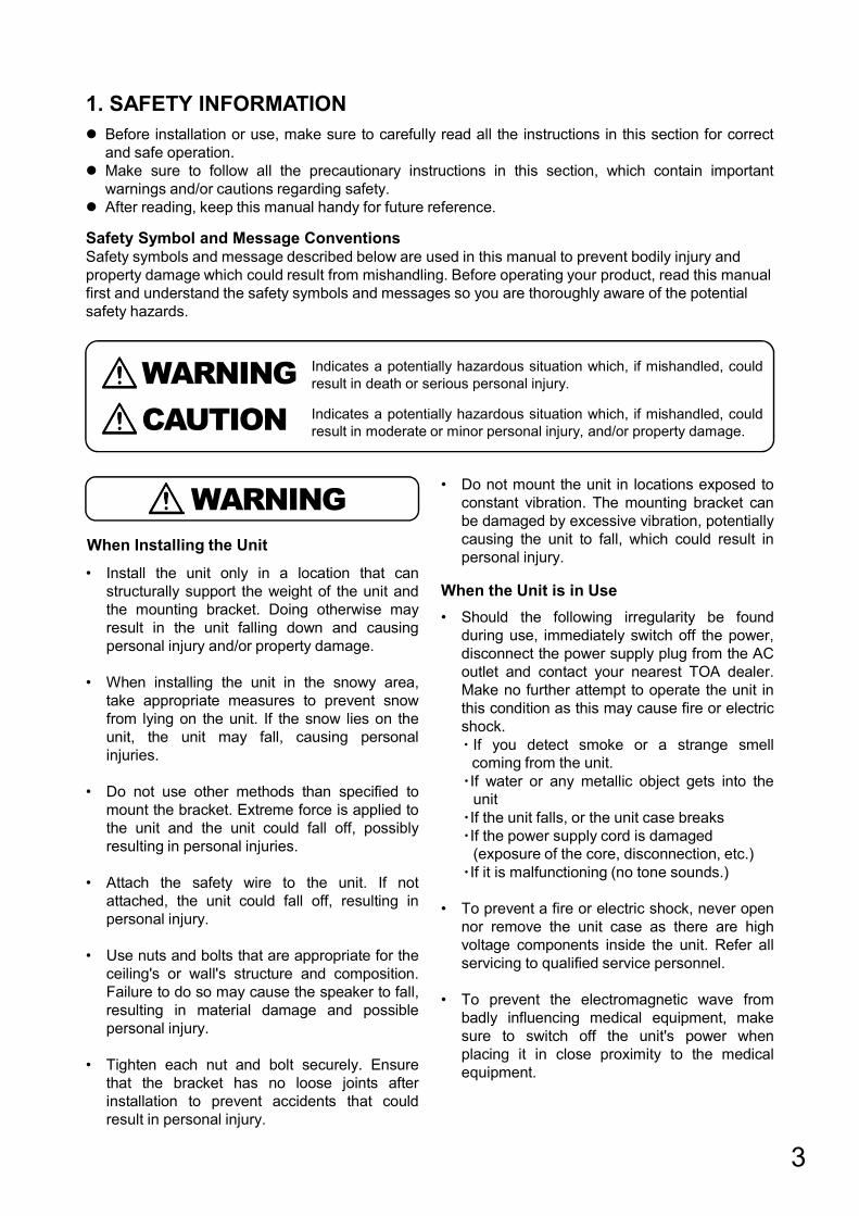
Indicates a potentially hazardous situation which, if mishandled, couldresult in death or serious personal injury.
Indicates a potentially hazardous situation which, if mishandled, couldresult in moderate or minor personal injury, and/or property damage.CAUTION
WARNING
WARNING

• Avoid touching the unit's sharp metal edge toprevent injury.
When Installing the Unit
• Do not stand or sit on, nor hang down from theunit as this may cause it to fall down or drop,resulting in personal injury and/or propertydamage.
• Have the unit checked periodically by the shopfrom where it was purchased. Failure to do somay result in corrosion or damage to the unitor its mounting bracket that could cause theunit to fall, possibly causing personal injury.
• Be sure to observe the following instructions.Failure to do so may cause hearingimpairment.・Reduce the volume to its lowest setting
before use.・Never use the unit close to a person's ear.・Point the unit in the direction where there is
no one when conducting operational tests.
When the Unit is in Use• Do not place heavy objects on the unit as this
may cause it to fall or break which may resultin personal injury and/or property damage. Inaddition, the object itself may fall off and causeinjury and/or damage.
• Do not operate the unit for an extended periodof time with the sound distorting. Doing somay cause the connected speakers to heat,resulting in a fire.
FCC REQUIREMENTS
NoteThis equipment has been tested and found to comply with the limits for a Class A digital device, pursuant to part 15 of the FCC Rules. These limits are designed to provide reasonable protection against harmful interference when the equipment is operated in a commercial environment. This equipment generates, uses, and can radiate radio frequency energy and, if not installed and used in accordance with the instruction manual, may cause harmful interference to radio communications.Operation of this equipment in a residential area is likely to cause harmful interference in which case the user will be required to correct the interference at his own expense.
ModificationsAny modifications made to this device that are not approved by TOA Corporation may void the authority granted to the user by the FCC to operate this equipment.
Warning: Operation of this equipment in a residential environment could cause radio interference.
4
CAUTION
2. OVERVIEWTOA's UC-4SC615 is an IP horn speaker which can be directly connected to an IP network as anendpoint device with a single network cable. Voice announcement, two-way communication, and audiomonitoring can be achieved through network. Thanks to its powerful sound and IP66 enclosure, theaudio information can be clearly heard even in outdoor spaces. The UC-4SC615 supports varioustypes of industrial standard network protocols and it can be a great option for VMS (Video ManagementSystem) and other network audio communication system integrations.

3. FEATURESConversation・SIP conversation with SIP telephones or other audio communication devices using SIP protocol.・ONVIF conversation with VMS software.Paging・Multi-cast paging can be received from 10 different stations.・Background music can be selected from the internal audio source play-list. (Can be used by future updates)Monitoring・Audio stream being monitored by VMS with ONVIF.・Control Input and Control Output are available.
4. NAMES AND FUNCTIONS
Bracket Dimensions
Rear Panel without Back Cover1
2
3
4
5
6
7
9
8
5

1. System Status Indicators 6. External Control Input and Relay OutputBy control input, you can play internal audio source and call to SIP telephone.By connecting the relay output to a flashlight etc., you can indicate the status such as broadcasting.
7. USB Connection TerminalConnect a USB memory to this terminal for internal audio play back. (Can be used by future updates)The size of USB device must be58 x 17 x 11 mm (H x W x D) or less.
Indicator Activity System Status
Blue
Pow
er O
N
During startup orIn broadcasting
Green Waiting
Yellow Failure orInitialization in progress
Extinguished Power OFF
2. Back CoverCovers the connector panel. Install the cable after connecting it to the speaker.
3. Cable GlandAttaches and secures the end of LAN cable or contact cable.Recommended cable: φ”4.5~6.0”mm
4. MicrophoneFor picking up ambient sounds or for two-way talk.
5. LAN Connection TerminalTo connect a LAN cable for PoE power supply.
8. RESET ButtonPress this button to restart the speaker.
9. Signal GrandConnect a ground wire to earth ground.
(58mm)
(17m
m)
(11m
m)
5. INSTALLATION PRECAUTIONSIMPORTANTDo not set up above the horizontal direction.
6
IMPORTANTAttach the safety wire to the unit. If not attached, the unit could fall off, resulting in personal injury.

6. INSTALLATION
Step 1.Separate the cable gland components from each other.
6.1. How to use the Cable GlandFollow the instructions below when installing the LAN cable.*Recommended cable: φ”4.5~6.0”mm
Step 2.Pass through RJ-45 connector and caulk cable.
Step 3.Fix all the components except for the lid.
Step 4.Close the lid.
6.2. Network Connection
From PoE/PoE+ switching hub
The US-4SC615 automatically recognizes the network types(10 BASE-T or 100 BASE-TX) and start a network connection. For this connection, use a straight UTP Category 5 or greater LAN (Ethernet) cable terminated with an RJ-45 connector.
Power can be supplied from the PoE / PoE+ switching hub when this terminal is connected to it.In this case, use the switching hub, which is “IEED802.3af compliant”.
When power is supplied from the PoE switching hub, be sure to use either PoE/PoE+ (IEEE802.3 af/at).The use of the switching hub other than the specified one may cause a fire.
6.3. Terminal Plug ConnectionUse the removable plugs supplied with the UC-4SC615 unit to connect the terminals by following the instructions below
Avoid soldering cable conductor, as contact resistance may increase when the cable is tightened and the solder is crushed, possibly resulting in an excessive rise in joint temperatures.
[ Recommended Cable ]SOLID WIRE: 24-16 AWG / 0.51-1.29mmSTRANDED WIRE: 24-16 AWG / 0.205-1.31 mm²WIRE STRIP LENGTH: 6-8mm
[ CTRL IN ] No-voltage make contact inputOpen-circuit voltage: 12 V DC or lessShort-circuit current: 2 mA or less
[ CTRL OUT ] Relay contact outputWithstand voltage: 40 V DCControl current: 2 to 300 mA
7
CAUTION
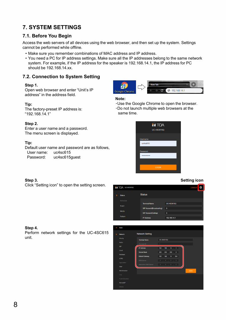
7. SYSTEM SETTINGS7.1. Before You BeginAccess the web servers of all devices using the web browser, and then set up the system. Settings cannot be performed while offline.
7.2. Connection to System SettingStep 1.Open web browser and enter “Unit’s IP address” in the address field.
Tip:The factory-preset IP address is: “192.168.14.1”
Step 2.Enter a user name and a password.The menu screen is displayed.
Tip:Default user name and password are as follows,User name: uc4sc615Password: uc4sc615guest
Step 3.Click “Setting icon” to open the setting screen.
8
Note:・Use the Google Chrome to open the browser.・Do not launch multiple web browsers at the
same time.
Step 4.Perform network settings for the UC-4SC615unit.
Setting icon
• Make sure you remember combinations of MAC address and IP address.• You need a PC for IP address settings. Make sure all the IP addresses belong to the same network
system. For example, if the IP address for the speaker is 192.168.14.1, the IP address for PC should be 192.168.14.xx.
nelso
Text Box
admin guest
nelso
Sticky Note
Unmarked set by nelso
nelso
Text Box
admin
nelso
Text Box
••••••••

8. INITIALIZATIONFollow the procedure below to restore the UC-4SC615 unit to its default setting states:
Step 1.Connect a LAN cable and restart UC-4SC615 while pressing the Reset switch.
Initialized setting:Login User nameLogin PasswordIP address (Default IP: 192.168.14.1)Subnet MaskDefault Gateway
Note:Make sure the status indicator changing yellow. The initialization has been completed by then.
Step 2.Open the web browser and enter “Unit’s IP address” in the address field.And enter a user name and a password.The menu screen is displayed.
Tip:IP address: 192.168.14.1User name: uc4sc615Password: uc4sc615guest
Reset switch
9
Step 4.Click “RESET” to restore all the settings to their original states.
Step 3.Click “Setting icon” to open the setting screen.And click “Maintenance” to open the Maintenance screen.
Setting icon
nelso
Text Box
admin guest
nelso
Text Box
admin
nelso
Text Box
••••••••

9. SOFTWARE LICENSE INFORMATIONThe UC-4SC615 employs software based on the following open-source software licenses:
• GNU General Public License version 1 (GPL-1.0)• GNU General Public License version 2 (GPL-2.0)• GNU General Public License version 3 (GPL-3.0)• GNU Affero General Public License version 3 (AGPL-3.0)• GNU Lesser General Public License version 2 (LGPL-2.0)• GNU Lesser General Public License version 2.1 (LGPL-2.1)• GNU Lesser General Public License version 3 (LGPL-3.0)• Mozilla Public License version 2.0 (MPL-2.0)• IBM ICU License (ICU)• Artistic License 1.0 (Artistic-1.0)• Eclipse Distribution License 1.0 (EDL-1.0)• libgsm License• The 3-Clause BSD License• The 2-Clause BSD License• MIT License (MIT)• Apache License 2.0 (Apache-2.0)• Academic Free License version 2.0 (AFL-2.0)• Eclipse Public License 1.0 (EPL-1.0)• Freetype Project License (FTL)• Iozone License version 3• ISC License (ISC)• libbzip2 License version 1.0.6• libpng License version 1.2.6• NTP License (NTP)• OpenLDAP Public License version 2.8• OpenSSL License• PHP License version 3.01 (PHP-3.01)• Python Software Foundation License version 2 (PSF-2.0)• zlib License• Others
We do not guarantee the operation of open-source software itself, but we do guarantee the functionality of such software incorporated within the UC-4SC615 according to the provision of each license.
For Specific Open-Source Software InformationPlease contact your nearest TOA dealer if you require details about any of the open-source software incorporated within the UC-4SC615. However, we will not be able to respond to inquiries about the contents of the open source.
10

10. SPECIFICATIONSPower Source PoE / PoE+ (IEEE802.3af/at) (via RJ-45)Power Consumption 13W (Use of the PoE)
22W (Use of the PoE+)Microphone Electret Condenser MicrophoneAmplifier Rated Output 8W (Use of the PoE)
15W (Use of the PoE+)Sensitivity 121dB (15W, 1m) (500Hz - 2.5kHz, peak level)
109dB (1W, 1m) (500Hz – 2.5kHz, peak level)110dB (15W, 1m) (100Hz – 10kHz, pink noise)107dB (8W, 1m) (100Hz – 10kHz, pink noise)
Frequency Response 315 Hz – 12.5kHzSampling Frequency 8kHz-48kHzAudio Codec G.711u/a, G.722, L16 (8 – 48kHz)Network Interface 10BASE-T/100BASE-TX, RJ-45Network Protocol TCP/IP, UDP, HTTP, RTP, ARP, ICMP, RTSP,
SIP (RFC3261), ONVIF v17.12Control Input 1channel, no-voltage make contact input, open voltage: 5 V DC,
short-circuit current: 2 mA or less, removable terminal block (5pins)Control Output 1channel, relay contact output, withstand voltage: 30 V DC,
control current: max.300 mA, removable terminal block (5pins)USB Interface USB2.0 Type-A 1portIndicator LAN LINK/ACT, (Yellow/Green)
STATUS (Yellow/Green/Blue)Dust/Water Protection IP66Operating Temperature -20 to +55℃ (-4°F to +131°F)Operating Humidity 90% RH or less (no condensation)Finish Horn flare and body: Aluminum, off-white (RAL 9010 equivalent), paint
Rear cover: ABS resin, off-white (RAL 9010 equivalent), paintReflector horn: ABS resin, off-white(RAL 9010 equivalent)Bracket, screws and bolts: Stainless steel
Dimensions 222(W) ×231(H) ×296(D) mm( 8.74“ × 9.09 “ × 11.65 “ )
Weight 1.5kg (3.31 lb)Option Speaker mount bracket: SP-131
Pole band: YS-60BSpeaker mount bracket: SP-301Speaker mount bracket: SP-201Swivel bracket: YS-151S
11

www.toacanada.com
Traceability Information for EuropeManufacturer:
TOA Corporation7-2-1, Minatojima-Nakamachi, Chuo-ku, Kobe, Hyogo, Japan
Authorized representation:TOA Electronics Europe GmbHSuederstrasse 282, 20537 Hamburg, Germany
TOA CANADA CORPORATION